EP2876807A2 - Phasenstromregelung in BLDC-Motoren - Google Patents
Phasenstromregelung in BLDC-Motoren Download PDFInfo
- Publication number
- EP2876807A2 EP2876807A2 EP14194460.3A EP14194460A EP2876807A2 EP 2876807 A2 EP2876807 A2 EP 2876807A2 EP 14194460 A EP14194460 A EP 14194460A EP 2876807 A2 EP2876807 A2 EP 2876807A2
- Authority
- EP
- European Patent Office
- Prior art keywords
- phase
- current
- determining
- zero
- field effect
- Prior art date
- Legal status (The legal status is an assumption and is not a legal conclusion. Google has not performed a legal analysis and makes no representation as to the accuracy of the status listed.)
- Granted
Links
Images


Classifications
-
- H—ELECTRICITY
- H02—GENERATION; CONVERSION OR DISTRIBUTION OF ELECTRIC POWER
- H02P—CONTROL OR REGULATION OF ELECTRIC MOTORS, ELECTRIC GENERATORS OR DYNAMO-ELECTRIC CONVERTERS; CONTROLLING TRANSFORMERS, REACTORS OR CHOKE COILS
- H02P6/00—Arrangements for controlling synchronous motors or other dynamo-electric motors using electronic commutation dependent on the rotor position; Electronic commutators therefor
- H02P6/14—Electronic commutators
- H02P6/16—Circuit arrangements for detecting position
- H02P6/18—Circuit arrangements for detecting position without separate position detecting elements
- H02P6/182—Circuit arrangements for detecting position without separate position detecting elements using back-emf in windings
-
- H—ELECTRICITY
- H02—GENERATION; CONVERSION OR DISTRIBUTION OF ELECTRIC POWER
- H02P—CONTROL OR REGULATION OF ELECTRIC MOTORS, ELECTRIC GENERATORS OR DYNAMO-ELECTRIC CONVERTERS; CONTROLLING TRANSFORMERS, REACTORS OR CHOKE COILS
- H02P6/00—Arrangements for controlling synchronous motors or other dynamo-electric motors using electronic commutation dependent on the rotor position; Electronic commutators therefor
- H02P6/08—Arrangements for controlling the speed or torque of a single motor
- H02P6/085—Arrangements for controlling the speed or torque of a single motor in a bridge configuration
-
- H—ELECTRICITY
- H02—GENERATION; CONVERSION OR DISTRIBUTION OF ELECTRIC POWER
- H02P—CONTROL OR REGULATION OF ELECTRIC MOTORS, ELECTRIC GENERATORS OR DYNAMO-ELECTRIC CONVERTERS; CONTROLLING TRANSFORMERS, REACTORS OR CHOKE COILS
- H02P6/00—Arrangements for controlling synchronous motors or other dynamo-electric motors using electronic commutation dependent on the rotor position; Electronic commutators therefor
- H02P6/30—Arrangements for controlling the direction of rotation
-
- H—ELECTRICITY
- H02—GENERATION; CONVERSION OR DISTRIBUTION OF ELECTRIC POWER
- H02H—EMERGENCY PROTECTIVE CIRCUIT ARRANGEMENTS
- H02H7/00—Emergency protective circuit arrangements specially adapted for specific types of electric machines or apparatus or for sectionalised protection of cable or line systems, and effecting automatic switching in the event of an undesired change from normal working conditions
- H02H7/08—Emergency protective circuit arrangements specially adapted for specific types of electric machines or apparatus or for sectionalised protection of cable or line systems, and effecting automatic switching in the event of an undesired change from normal working conditions for dynamo-electric motors
- H02H7/0833—Emergency protective circuit arrangements specially adapted for specific types of electric machines or apparatus or for sectionalised protection of cable or line systems, and effecting automatic switching in the event of an undesired change from normal working conditions for dynamo-electric motors for electric motors with control arrangements
- H02H7/0838—Emergency protective circuit arrangements specially adapted for specific types of electric machines or apparatus or for sectionalised protection of cable or line systems, and effecting automatic switching in the event of an undesired change from normal working conditions for dynamo-electric motors for electric motors with control arrangements with H-bridge circuit
Definitions
- the present invention relates to the field of brushless direct current (BLDC) motors. More specifically it relates to a device and method for controlling and monitoring the operation of BLDC motors. In particular, embodiments of the present invention apply to sensorless control of sinusoidally driven BLDC motors in the special aspect of phase current alignment towards BEMF voltage.
- BLDC brushless direct current
- BLDC motors are today widely used in automotive as well as non-automotive applications. As opposed to classic brushed DC Motors, a BLDC motor always needs to have driving electronics.
- the driving electronics provide a rotating electric field in the stator coils, by applying a switching sequence of driving waveforms to these stator coils.
- the rotor itself is built up with permanent magnets, which will follow the rotating magnetic field of the stator coils.
- the rotor position information might be provided by a sensing unit such as for instance a Hall effect sensor or a rotary encoder, or can be derived in a sensorless way out of the voltage/current information on the motor terminals, for instance by measuring the back-electromotive force (BEMF) voltage in the undriven coils.
- a sensing unit such as for instance a Hall effect sensor or a rotary encoder
- BEMF back-electromotive force
- phase current during the BEMF sensing is less than 50 % of the maximum phase current.
- phase current during the BEMF sensing is less than 10 % of the maximum phase current. This leads to good, e.g. improved, or even optimal, EMC and acoustical noise behaviour.
- the present invention provides a method for determining a phase current direction and a zero-crossing moment of the phase current in a sinusoidally controlled brushless direct current motor.
- the brushless direct current motor comprises a coil per phase, wherein the phase of the brushless direct current motor is driven by a half bridge driver comprising a high side field effect transistor and a low side field effect transistor.
- the method comprises the following steps:
- Measuring the drain source voltages over the high side field effect transistors and low side field effect transistors for each phase allows to determine the direction of the current through the phase. It is an advantage of embodiments of the present invention that the zero-crossing moment T1 of the phase current can be determined by identifying the moment when the current changes direction.
- Determining the zero crossing of the phase current requires only to determine the current direction based on the drain source voltages over the high side field effect transistor and over the low side field effect transistor whereby a change in direction determines the zero crossing moment of the phase current. Therefore it is an advantage of embodiments of the present invention that the required computation power is small compared to methods where the phase current needs to be reconstructed out of a total current measurement. It is an advantage of embodiments of the present invention that the zero-crossing of the phase current can be determined without requiring calculation intensive algorithms. It is for example not required to reconstruct the complete phase current. Therefore less processing power as well as less RAM is required when comparing with other methodologies (for example the ones reconstructing the phase current).
- determining the zero-crossing moment of the phase is robust against non-linearities of the system. It is an advantage of embodiments of the present invention that the zero-crossing moment of the phase can be determined with a limited amount of filtering or sorting, when comparing with prior art solutions, of the measured data. Therefore, it is an advantage of embodiments of the present invention that the settling time caused by the filtering is reduced when comparing with prior art solutions.
- a software filter algorithm may be used, which increases reliability of the measured values used to generate interpolated values.
- determining the zero crossing moment of the phase current may comprise filling a current direction indication table with the current direction for each measurement.
- the current direction is stored for a sequence of measurements. This allows to better determine the zero-crossing moment of the phase current. Indeed, storing the direction of the current in a current direction indication table allows to average out noise artefacts occurring at the zero crossing of the phase current.
- the present invention provides a method for driving a sinusoidally driven brushless direct current motor.
- the brushless direct current motor comprises a coil per phase, wherein the phase of the brushless direct current motor is driven by a half bridge driver comprising a high side field effect transistor and a low side field effect transistor.
- the method comprises the following steps:
- a method according to embodiments of the present invention may furthermore comprise, before the step of determining a delay between the zero crossing moment of the current through the coil and a zero crossing moment of a back-electromotive force voltage over the coil,
- the phase current and the back-EMF voltage can be aligned. It is an advantage of embodiments of the present invention that the back-EMF voltage and the phase current can be aligned through a method according to embodiments of the present invention as this allows to run the motor in an energy efficient mode.
- an undriven period is provided in the driving waveform of the high side and low side field effect transistor. During this undriven period the back-EMF voltage is measured. It is an advantage of embodiments of the present invention that the undriven period is aligned with the zero-crossing of the phase current. By opening the BEMF measurement window when the phase current is changing its polarity, current spikes and fly back voltage pulses are avoided. This will lead to an optimal EMC and acoustical noise behaviour and improve the reliability of the BEMF measurements.
- the undriven period defines the measurement window during which the BEMF voltage can be measured. It is an advantage of embodiments of the present invention that a good alignment between the phase current and the BEMF voltage permits a small undriven period of the high side FET and the low side FET. The better the zero-crossing moment of the phase current and the zero-crossing moment of the BEMF are aligned the smaller the undriven period may be.
- the width of the undriven period may be adapted depending on the circumstances (e.g. the motor characteristics, the motor rotational speed). In embodiments of the present invention the width of the undriven period is longer when the motor is running at low speed than when it is running at high speed since at high speed the BEMF is larger and less sampling is required.
- the width of the undriven period is varying between 3 PWM periods and 60 PWM periods. In embodiments of the present invention the length of a PWM period is 50 ⁇ s. It is an advantage of embodiments of the present invention that the energy taken out of the system because of the undriven period can be limited as the undriven period can be relatively small.
- the driving waveform can be adjusted for any of the following dynamically changing parameters: rotor speed, loaded torque on the shaft, supply voltage, temperature.
- the required processing power for calculating the zero-crossing moment of the phase current is limited when comparing with other methods where for example a complete reconstruction of the phase current is required. Therefore it is an advantage of embodiments of the present invention that a higher dynamic behaviour can be obtained with regard to changing external parameters.
- determining the zero crossing moment T2 of the back-electromotive force voltage of the phase may comprise filling a back-electromotive force voltage table with the measured back-electromotive force voltages sampled during the undriven period of the phase.
- the back-electromotive force voltage is stored for a sequence of measurements as this allows to better determine the zero-crossing moment of the back-electromotive force voltages. Indeed, storing the back-electromotive force voltages allows to average out noise artefacts occurring at the zero crossing of back-electromotive force voltages.
- At least one of the driving waveforms may be pulse width modulated. It is an advantage of embodiments of the present invention that the methods can be applied for pulse width modulated driving waveforms as this allows to control the power transferred to the rotor using pulse width modulation.
- the total current may be measured by using a shunt resistor. This allows the phase currents to be reconstructed based on these total current measurements.
- the present invention provides a current monitoring device for determining the phase current direction and zero-crossing moment T1 of the phase current in a sinusoidally controlled brushless direct current motor.
- the brushless direct current motor comprises a coil per phase, wherein the phase of the brushless direct current motor is driven by a half bridge driver comprising a high side field effect transistor and a low side field effect transistor.
- the current monitoring device comprises:
- the present invention provides a device for driving a sinusoidally driven brushless direct current motor.
- the brushless direct current motor comprises a coil per phase, wherein the phase of the brushless direct current motor is driven by a half bridge driver, wherein the half bridge driver comprises a high side field effect transistor and a low side field effect transistor.
- the device for driving the sinusoidally driven BLDC motor comprises:
- FIGs. 1 to 3 the relationship between the back EMF voltage 102 and the phase current 101 of a phase A of a BLDC motor is shown.
- the back EMF 102 is synchronised with the phase current 101; in FIG. 2 , the back EMF 102 lags the phase current 101 and in FIG. 3 the back EMF 102 leads the phase current 101.
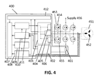
- a three phase BLDC motor 451 is illustrated, provided with half bridge drivers 453 and a device 400 for controlling and driving the half bridge drivers.
- the motor comprises a coil 452 per phase, and each phase of the BLDC motor is driven by a half bridge driver 453.
- the half bridge drivers 453 enable the phases to be driven by a desired voltage profile at a desired Pulse Width Modulation (PWM) duty cycle.
- PWM Pulse Width Modulation
- the application of a driving profile to the half bridge drivers 453 is controlled by six driving transistors, a high side field effect transistor 454 and a low side field effect transistor 455 for each half bridge driver 453, operable in response to a PWM duty cycle generation unit 411 to apply the driving profile at a desired PWM duty cycle.
- the supply voltage 456 for the high side and low side field effect transistors is provided by a battery.
- the driving profile is generated by a main control module 407, and its amplitude and duration are controlled by a motor control parameter calculation unit 409.
- the main control module 407 provides, based on speed/torque requirements of the motor 451, information to the PWM duty cycle generation unit 411, such as the current wave form profiles to be applied to the motor 451.
- the PWM duty cycle generation unit 411 then provides information about the switching sequence to the FET Driver Circuit 403, more particularly to the high side gate driver 404 and the low side gate driver 406 for correspondingly driving the driving transistors 454, 455 of the half bridge drivers 453.
- the high side gate driver 404 and low side gate driver 406 are driven according to the switching sequence, and provide switching information to the high side field effect transistors 454 and low side field effect transistors 455, respectively, which are thus driven with a driving waveform according to the applied switching sequences.
- a drain source voltage monitoring device 405 observes for each power FET 454, 455 in the high side and in the low side the drain source voltages and will interpret them by using the information of the PWM duty cycle generation unit 411, as explained below with reference to FIG. 8 and FIG. 9 .
- the information of the drain source monitoring device 405 is provided to a short circuit and overcurrent detection and handling unit 412.
- a current sense unit 402 is provided for determining the current through a shunt resistance 401 connected between ground and the low side FETs 455.
- This current sense unit 402 provides its current measurements to the short circuit and overcurrent detection and handling unit 412 and to a phase current reconstruction and alignment unit 410.
- one shunt resistor 401 measures the sum of all currents through the low side FETs 455.
- One shunt resistor 401 for measuring the sum of all currents instead of a shunt resistor per phase has the following advantages: only one shunt resistor is needed which decreases the system cost, the dissipated power is reduced, and therefore the heating of the module is also reduced.
- the phase reconstruction and alignment unit reconstructs the phase current based on the measurements of the current through the shunt resistor 401 and based on the switching moments of the high side FETs 454 and the low side FETs 455.
- the current through the shunt resistor 401 is sampled at dedicated moments during which the current is only flowing through one phase.
- the phase reconstruction and alignment unit determines where the current flows at a certain moment in time.
- the zero crossing of the phase current and the zero crossing of the BEMF are aligned.
- the three BLDC motor phases are connected to a back EMF measurement and analysis unit 408.
- the back EMF measurement and analysis unit is operable to measure the voltage of a motor phase while it is undriven in order to determine the back EMF zero crossing point. This thereby enables the rotor position and speed to be estimated.
- the information about the rotor position and the motor speed is provided by the back EMF measurement and analysis unit 408 to the main control module 407.
- a speed regulator / torque regulator compares and regulates the achieved parameters, e.g. motor speed and/or torque, to the requested parameters.
- the rotor position information is also provided to the motor control parameter calculation unit 409.
- the lead angle might be calculated, which may be used for adjustment in phase angle of the driving voltage profile.
- the phase current reconstruction and alignment unit 410 restores the phase currents 101 out of the current samples from the current sense unit 402 and from the PWM controlling scheme of the PWM duty cycle generation unit 411.
- the reconstructed phase currents might further be used by the main control module 407.
- the phase current reconstruction and alignment unit 410 uses the information of the drain source voltage monitoring device 405 and determines a current direction indicator (CDI).
- CDI current direction indicator
- the zero-crossing moment of the phase current 101 can be determined and that is used to align the stored current wave form profiles of the PWM duty cycle generation unit 411 towards the BEMF voltage from the BEMF measurement and analysis unit 408, for instance taking into account the lead angle determined by the motor control parameter calculation unit 409.
- the BLDC motor is driven conform a sinusoidal commutation mode.
- sinusoidal commutation mode one motor phase can be set to ground, while the both remaining motor phases are driven with a PWM switching scheme to generate the sinusoidal current shape (space vector modulation).
- phase current 101 For measuring a correct BEMF voltage it is required that the phase current 101 is zero while measuring the phase voltage 703. If the phase current 101 is not zero when interrupting the driving waveform this will cause the current to run out of the coil during the freewheel time. Therefore it is advantageous to measure the BEMF voltage at the zero-crossing moment of the phase current 101.
- the BEMF voltage measurement window leads to a discontinuity of the current. This discontinuity can generate audible noise and can deteriorate the EMC behaviour of the system, if the BEMF measurement is done at an unpropitious moment.
- FIG. 5 illustrates a first and a second graph where the BEMF measurement window is either opened too early (in the first graph - before the zero crossing moment T1) or too late (in the second graph - after the zero crossing moment T1).
- the curve 501 in FIG. 5 and FIG. 6 represents the ideal phase current. This is the phase current if the BEMF measurement window would not be opened. In that case no discontinuities are present in the phase current. When opening the BEMF measurement window, however, discontinuities in the phase current occur.
- the curve 101 illustrates the phase current when an undriven period is introduced in the phase for measuring the BEMF voltage.
- the BEMF voltage measurement window is opened too early.
- the current in the motor phase will continue to flow and will shoot into one bulk diode of a given power transistor 454, 455. This will lead to a so called fly back voltage pulse in the measurement window, what finally will disturb the BEMF measurement, resulting in a BEMF signal that is not reliable.
- the BEMF voltage measurement window is opened too late. This results in current spikes, producing audible noise and leading to a bad EMC behaviour.
- the BEMF voltage measurement window is opened at the same time as the current changes direction from positive current to negative current or vice versa. This is the optimal behaviour. At that moment, the current is zero and there are no current spikes. The loss in the produced torque can almost be neglected.
- the ideal timing of the driving waveforms can be defined for a given load condition (motor speed, torque, voltage etc.). However, as BLDC motors are inductive loads, the optimal timing will change with the changing load conditions. When load conditions are changing the timing of the driving waveforms should be adapted such that the BEMF measurement window again coincides with a zero crossing of the current.
- this information is obtained from another measurement, namely from the measurement of the drain source voltage of the power transistors 454, 455. This is explained in more detail with reference to FIG. 7 .
- the current direction can indirectly be observed by the drain source voltage monitoring inside the FET driver circuit, as performed by the VDS monitoring circuit 405.
- An embodiment of such VDS monitoring circuit is illustrated in more detail in FIG. 7 .
- a first drain source voltage comparator 701 for the high side and a second drain source voltage comparator 702 for the low side are used for monitoring the phase (drain source) voltage 703.
- the two comparators 701, 702 deliver information about the phase voltage 703.
- error conditions may be triggered if the drain source voltage is outside a pre-defined condition (error case - signal VDS Error).
- the comparators 701, 702 deliver information about the phase current flowing either in positive or in negative direction. This information can be used to determine the phase current direction and eventually the zero-crossing moment of the phase current. Based on this information, a current direction indicator (CDI) flag may be set.
- CDI current direction indicator
- the CDI flag is a current direction indication bit, which is set depending on the direction of the current.
- a current direction indication bit which is set depending on the direction of the current.
- drain source voltage comparators switching from high side active to low side active and reverse with positive current or negative current flowing, etc.
- FIG. 8 and FIG. 9 illustrate the measured gate voltages and phase voltage 703 when switching from high side active to low side active in two situations: a first situation when the phase current 101 is positive, and a second situation when the phase current 101 is negative.
- the high side gate driver 404 is switched off and the low side gate driver 406 is switched active while the phase current 101 is positive.
- the high side gate driver 404 output is set from active to inactive and the high side FET 454 starts to switch off.
- the phase voltage 703 also starts to drop after the high side FET 454 goes from saturation into the linear region.
- the gate voltage 704 of the high side FET 454 and the phase voltage 703 both fall after a while below 0 V.
- both the high side FET 454 as well as the low side FET 455 are turned off and the drain source voltage comparator 701, 702 detects the actual phase voltage 703.
- the phase voltage 703 is already below battery voltage and the current direction indication bit indicates 1 (positive current).
- the high side gate driver 404 is switched off and the low side gate driver 406 is switched active while the phase current 101 is negative.
- the high side gate driver output 404 is set from active to inactive, and the high side gate voltage 704 drops to battery voltage but not to 0 V.
- the phase current 101 is negative and it is driving the phase voltage 703 to battery voltage because of the inductance of the motor coil.
- the phase current 101 is freewheeling.
- both the high side FET 454 as well as the low side FET 455 are in tri-state and the drain source voltage comparator 701, 702 detects the actual phase voltage.
- the current direction indication bit is set to 0 indicating that the current is negative.
- the low side gate driver output 406 is set to active and the low side FET 455 turns on (see low side gate voltage 705 in FIG. 9 ) and the high side gate voltage 704 and the phase voltage 703 are pulled to ground.
- the zero crossing moment of the current can be identified by monitoring the drain source voltage of the power transistors 454, 455. From the drain source voltages of the power transistors 454, 455, the current direction can be derived.
- the phase current zero-crossing moment T1 on its turn can be derived from the current direction as being the moment when the phase current 101 changes direction.
- the subsequent current directions may be stored in a table, referred to as the current direction indication (CDI) table.
- CDI current direction indication
- the zero-crossing moment of the phase current 101 can be determined by inspecting this table. Using a table allows to average out noise artefacts occurring at the zero crossing of the phase current.
- the current indication signal for instance current direction indication bit
- the current indication signal can be used to determine the zero-crossing moment of the phase. This is an advantage because it is a computation inexpensive way of determining the zero-crossing of the phase current compared to methods where the complete phase currents need to be rebuilt.
- knowing the phase current zero-crossing moment allows to find the optimal position for the BEMF voltage measurement. Knowing the phase current zero-crossing moment also allows to align the phase current 101 in an easy way towards the BEMF voltage in order to drive the motor in an energy optimal way.
- Error detection and the current direction determination is implemented in the module 706 in FIG. 7 . Therefore it uses the output of the drain source voltage comparator 701 of the high side and the output of the drain source voltage comparator 702 at the low side.
- the reference voltage level 707 for the high side and the reference voltage level 708 for the low side are programmable.
- the reference voltage level 707 for the high side can be varied to a level between the battery voltage (supply voltage 456) and the battery voltage minus 2.5 V.
- the reference voltage level 708 for the low side can be varied to a level between 0 V and 2.5 V. It is an advantage of embodiments of the present invention that the reference voltage levels can be adapted for drain source voltage monitoring and for error detection.
- the present invention relates to a method 1010 for determining the direction of the phase current 101 in a sinusoidally driven BLDC motor 451 and for determining the zero-crossing moment T1 of this phase current 101.
- Embodiments of the present invention can be used for driving a sinusoidally driven BLDC motor, an exemplary BLDC motor being shown in and described with respect to FIG. 4 .
- FIG. 10 shows the two steps, according to embodiments of the present invention, of a method 1010 for determining the zero crossing moment T1 of the phase current 101.
- the drain source voltages over the high side field effect transistor 454 and over the low side field effect transistor 455 are measured.
- the current direction is determined from these drain source voltages, and when the current changes direction the zero crossing timestamp T1 is noted.
- FIG. 10 sub-method 1010, also shows a loop indicating that the measurements are done continuously. How the loop is closed, however, can differ between embodiments. Different steps might be included and not each step needs to be executed in every loop.
- FIG. 10 also illustrates a broader method 1000 for sinusoidally driving a BLDC motor 451.
- the method 1000 comprises several steps which may be executed consecutively or in parallel. Embodiments are illustrated in FIG. 10 , FIG. 11 and FIG. 12 .
- a driving waveform is applied to each field effect transistor (454, 455) of each phase.
- Each of the driving waveforms has an undriven period, which optimally has a timing as explained with respect to FIG. 6 .
- Step 1010 the zero crossing moment T1 of the phase current 101 is determined based on the measured 1011 drain source voltages over the high and low side field effect transistors 454, 455, and determining 1012 therefrom a current direction indication, which indicates a zero crossing moment when it indicates the current direction switches.
- Steps 1011 and 1012 may be running in a parallel process 1010 (as in FIG. 10 ) or may be integrated with other method steps (e.g. FIG. 11 and FIG. 12 ).
- step 1021 the delay between the zero crossing moment T1 of the current 101 through the coil 452 and the zero crossing moment T2 of the back-electromotive force voltage over the coil 452 is determined. This delay is used in step 1022 for adjusting 1022 the driving waveforms with the delay such that the zero crossing of the phase current substantially corresponds with the zero crossing of the back-electromotive force voltage, as illustrated in FIG. 1 .
- Steps 1021 and 1022 may be running in a parallel process 1020 ( FIG. 10 ) or may be integrated with other method steps (e.g. FIG. 11 and FIG. 12 ).
- step 1031 the BEMF voltage is measured during an undriven period of the phase.
- the zero crossing moment T2 of the BEMF voltage is determined based on the measured the BEMF voltages. This may be done in any suitable way. In embodiments of the present invention the zero-crossing moment of the BEMF voltage is calculated through interpolation from BEMF samples. In alternative embodiments, the sampled BEMF voltages may be stored in a BEMF voltage table. Interpolation of the samples in the BEMF voltage table allows to determine the zero-crossing momentT2 of the BEMF voltage.
- step 1021 the delay between the zero crossing moment T1 of the current through the coil and the zero crossing moment T2 of the back-electromotive force voltage over the coil 452 is then determined, e.g. calculated.
- step 1033 the driving waveforms are adjusted with the delay such that the zero crossing of the phase current 101 substantially corresponds with the zero crossing of the back-electromotive force voltage, and/or the power of the driving waveforms is adjusted.
- Steps 1031 and 1032, 1021 and 1033 may be running in a parallel process 1030 ( FIG. 10 ) or may be integrated with other method steps (e.g. FIG. 12 ).
- the sub-method 1010 for determining the zero-crossing moment of the phase current 101, and any of sub-methods 1020, 1030 for adjusting the delay between zero-crossing of BEMF voltage and phase current 101, can be applied in parallel as illustrated in FIG. 10 .
- FIG. 11 illustrates the determination 1010 of the zero-crossing moment of the phase current 101 being carried out, by measuring 1011 the drain source voltage of the power transistors 454, 455. This determination is looped as long as no zero-crossing of the phase current 101 is detected. As soon as a zero-crossing is detected, a delay between the zero-crossing moment T1 of the phase current 101 and the zero-crossing moment T2 of the BEMF voltage is determined 1021; and this delay is used for correcting 1022 the driving waveform.
- FIG.12 is similar to the embodiments illustrated in FIG. 11 , but furthermore includes the sub-method 1030 of BEMF measurement and zero-crossing moment T2 determination.
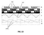
- FIG. 13 shows the current direction indication bit 1301, and the phase voltage 703 for every motor phase U, V, W.
- the undriven periods are clearly visible in the phase voltage 703.
- the phase current 101 for phase V is also shown.
- the undriven periods are at the same moment as the zero-crossing moments of the phase current 101 as can be seen from the motor phase current line 101 and from the current direction indication line 1301.
- FIG. 13 thus shows the optimal condition for opening the BEMF voltage measurement window. At the moment where the phase 101 current crosses the zero line, the BEMF voltage measurement window is opened.
- the driving waveform e.g. sine wave table
- offset correction can be done in every motor state and in every motor phase.
- a motor state is the time between two motor commutations.
- FIG. 14 shows the phase voltage 703 and the phase current 101 for one phase. While the external load of the BLDC motor 451 increases (the current amplitude rises as well) the BEMF measurement window is always kept at the zero crossing of the motor phase current (optimal position). It is therefore an advantage of embodiments of the present invention that the method 1000 is very robust under hard environments and changing load conditions. Hard environments may for example occur in automotive applications where the supply voltage 456 can change between 5 V and 45 V and/or where the temperature can vary between -40°C and +150°C. This implies that the motor current is not only dependent on the motor load and speed but also on the environmental conditions.
- Embodiments of the present invention enable starting an Engine Cooling Fan of 600 W from 0 to maximum speed in 5.6 seconds whereas in prior art solutions for the same fan at least the double of this time was required.
- Embodiments of the present invention applied in an oil pump responded to changing loads of 70 bar in less than 150 ms whereas this was less reliable in prior art solutions.
- an alignment between the BEMF voltage and the phase current leads to an energy efficiency increase. In embodiments of the present invention an energy saving can be realised between 5% and 15% compared to prior art solutions.
- a phase current reconstruction and alignment unit 410 uses the current direction indication bit information and shifts the stored driving waveform (e.g. sine wave tables) of the PWM duty cycle generation unit 411 with an offset either to the left side or to the right side depending on the delay between the zero-crossing moment of the phase current and the zero-crossing moment of the BEMF voltage.
- the phase current 101 and the BEMF voltage 102 are perfectly in sync. In this situation the BLDC motor 451 runs in an energy efficient mode.
- FIG. 2 and FIG. 3 a delay is present between the BEMF voltage 102 and the phase current 101. In the first case the BEMF voltage 102 is delayed in the second case it is the phase current 101.
- the driving waveform is shifted such that the phase current 101 and the BEMF voltage 102 are in sync.
- This shift is done with a simple addition of a positive or negative variable offset.
- This operation is very fast with minimum calculation efforts.
- the BEMF voltage measurement window is always placed at that moment, when the phase current changes its polarity, thus at the moment when the phase current is nearly zero. Therefore it is an advantage of embodiments of the present invention that changes in load or changes in speed of the motor are regulated out.
- transient effects are reduced since the undriven period is at the zero crossing of the phase current 101. Reducing the transient effects results in less EMC disturbances and in less acoustic noise.
- the present invention relates to a current monitoring device 710 for determining the phase current 101 direction and zero crossing moment T1 of the phase current in a sinusoidally controlled BLDC motor 451.
- the BLDC motor 451 comprises a coil 452 per phase.
- the phase of the BLDC motor 451 is driven by a half bridge driver 453, wherein the half bridge driver comprises a high side field effect transistor 454 and a low side field effect transistor 455.
- the current monitoring device 710 comprises a drain source voltage monitoring device 405 for monitoring the drain source voltage over the field effect transistors 454, 455. It also comprises a processing device 1520 for determining the phase current 101 direction and for determining the moment the phase current changes direction thus identifying the zero-crossing moment T1 of the phase current 101.
- the present invention relates to a device 400 for driving a sinusoidally driven BLDC motor 451.
- the device 400 comprises a current monitoring device 710 for determining the zero-crossing moment of the phase current 101.
- the device 400 moreover comprises a BEMF voltage measurement and analysis unit 408 for measuring the BEMF voltage, and for determining the zero-crossing moment of the BEMF voltage T2.
- the device also comprises a synchronization unit 1510 for time shifting the driving waveform such that the phase current 101 and the BEMF voltage are aligned.
Landscapes
- Engineering & Computer Science (AREA)
- Power Engineering (AREA)
- Control Of Motors That Do Not Use Commutators (AREA)
Applications Claiming Priority (1)
| Application Number | Priority Date | Filing Date | Title |
|---|---|---|---|
| GB1320718.8A GB2520538A (en) | 2013-11-25 | 2013-11-25 | Phase current regulation in BLDC motors |
Publications (3)
| Publication Number | Publication Date |
|---|---|
| EP2876807A2 true EP2876807A2 (de) | 2015-05-27 |
| EP2876807A3 EP2876807A3 (de) | 2016-02-10 |
| EP2876807B1 EP2876807B1 (de) | 2023-02-22 |
Family
ID=49918117
Family Applications (1)
| Application Number | Title | Priority Date | Filing Date |
|---|---|---|---|
| EP14194460.3A Active EP2876807B1 (de) | 2013-11-25 | 2014-11-24 | Phasenstromregelung in BLDC-Motoren |
Country Status (4)
| Country | Link |
|---|---|
| US (1) | US9479096B2 (de) |
| EP (1) | EP2876807B1 (de) |
| JP (1) | JP2015109792A (de) |
| GB (1) | GB2520538A (de) |
Cited By (4)
| Publication number | Priority date | Publication date | Assignee | Title |
|---|---|---|---|---|
| CN105897081A (zh) * | 2016-06-29 | 2016-08-24 | 苏州联芯威电子有限公司 | 一种无位置传感器无刷直流电机的低速启动方法 |
| WO2020157507A1 (en) * | 2019-01-30 | 2020-08-06 | Digipulse Ltd | Signal sampling and filtering for motor position estimation |
| CN112994542A (zh) * | 2021-04-29 | 2021-06-18 | 常州工业职业技术学院 | 基于换相点换相的无刷直流电机无感控制方法 |
| WO2022064188A1 (en) * | 2020-09-25 | 2022-03-31 | Dyson Technology Limited | A method of determining a position of a rotor of a brushless permanent magnet motor |
Families Citing this family (7)
| Publication number | Priority date | Publication date | Assignee | Title |
|---|---|---|---|---|
| US10338142B2 (en) * | 2014-06-30 | 2019-07-02 | Elmos Semiconductor Ag | Faulty load detection for multi-phase electric motor |
| US9991827B1 (en) * | 2017-02-06 | 2018-06-05 | Texas Instruments Incorporated | Methods and apparatus for automatic lead angle adjustment using fly-back voltage for brushless DC control |
| JP7268941B2 (ja) * | 2019-11-13 | 2023-05-08 | ▲広▼▲東▼美的白色家▲電▼技▲術▼▲創▼新中心有限公司 | モータの位相変換誤差補償方法、装置及び記憶媒体 |
| TWI793517B (zh) * | 2021-02-05 | 2023-02-21 | 陞達科技股份有限公司 | 馬達系統及馬達驅動方法 |
| CN113224986B (zh) * | 2021-05-17 | 2022-10-21 | 深圳市航顺芯片技术研发有限公司 | 直流无刷电机以及直流无刷电机的控制方法 |
| IT202100022217A1 (it) | 2021-08-24 | 2023-02-24 | St Microelectronics Srl | Procedimenti e sistemi di rilevamento della forza elettromotrice inversa nei motori elettrici |
| GB2618358A (en) * | 2022-05-05 | 2023-11-08 | Dyson Technology Ltd | A method of determining a position of a rotor of a brushless permanent magnet motor |
Family Cites Families (6)
| Publication number | Priority date | Publication date | Assignee | Title |
|---|---|---|---|---|
| US6121736A (en) | 1998-07-10 | 2000-09-19 | Matsushita Electric Industrial Co., Ltd. | Control apparatus for motor, and motor unit having the control apparatus |
| DE19846831B4 (de) | 1998-10-10 | 2008-05-29 | Diehl Ako Stiftung & Co. Kg | Verfahren und Vorrichtung zur Ermittlung der Rotorstellung von Synchronmotoren |
| US7365506B2 (en) * | 2004-06-15 | 2008-04-29 | Matsushita Electric Industrial Co., Ltd. | Motor driving device, motor driving method, and motor apparatus |
| JP4906890B2 (ja) * | 2009-06-02 | 2012-03-28 | 三菱電機株式会社 | ブリッジ整流回路 |
| GB0916543D0 (en) | 2009-09-21 | 2009-10-28 | Melexis Tessenderlo Nv | Control of sinusoidally driven brushless dc (bldc) motors |
| DE102010029558A1 (de) | 2010-06-01 | 2011-12-01 | Robert Bosch Gmbh | Verfahren und Vorrichtung zum Ermitteln eines Nulldurchgangs eines Strangstroms einer elektronisch kommutierten elektrischen Maschine, insbesondere zur Ermittlung einer Läuferlage der elektrischen Maschine |
-
2013
- 2013-11-25 GB GB1320718.8A patent/GB2520538A/en not_active Withdrawn
-
2014
- 2014-11-03 US US14/531,224 patent/US9479096B2/en active Active
- 2014-11-17 JP JP2014232908A patent/JP2015109792A/ja active Pending
- 2014-11-24 EP EP14194460.3A patent/EP2876807B1/de active Active
Non-Patent Citations (1)
| Title |
|---|
| None * |
Cited By (6)
| Publication number | Priority date | Publication date | Assignee | Title |
|---|---|---|---|---|
| CN105897081A (zh) * | 2016-06-29 | 2016-08-24 | 苏州联芯威电子有限公司 | 一种无位置传感器无刷直流电机的低速启动方法 |
| WO2020157507A1 (en) * | 2019-01-30 | 2020-08-06 | Digipulse Ltd | Signal sampling and filtering for motor position estimation |
| WO2022064188A1 (en) * | 2020-09-25 | 2022-03-31 | Dyson Technology Limited | A method of determining a position of a rotor of a brushless permanent magnet motor |
| US12316265B2 (en) | 2020-09-25 | 2025-05-27 | Dyson Technology Limited | Method of determining a position of a rotor of a brushless permanent magnet motor |
| CN112994542A (zh) * | 2021-04-29 | 2021-06-18 | 常州工业职业技术学院 | 基于换相点换相的无刷直流电机无感控制方法 |
| CN112994542B (zh) * | 2021-04-29 | 2023-07-11 | 常州工业职业技术学院 | 基于换相点换相的无刷直流电机无感控制方法 |
Also Published As
| Publication number | Publication date |
|---|---|
| JP2015109792A (ja) | 2015-06-11 |
| GB2520538A (en) | 2015-05-27 |
| EP2876807A3 (de) | 2016-02-10 |
| GB201320718D0 (en) | 2014-01-08 |
| US9479096B2 (en) | 2016-10-25 |
| US20150145455A1 (en) | 2015-05-28 |
| EP2876807B1 (de) | 2023-02-22 |
Similar Documents
| Publication | Publication Date | Title |
|---|---|---|
| US9479096B2 (en) | Phase current regulation in BLDC motors | |
| US10523143B2 (en) | Sensorless BDLC control | |
| US8278860B2 (en) | Variable pulse width modulation for reduced zero-crossing granularity in sensorless brushless direct current motors | |
| EP1942575B1 (de) | Verfahren und Vorrichtung zum Treiben eines Gleichstrommotors | |
| US9071172B2 (en) | Sine modified trapezoidal drive for brushless DC motors | |
| KR101904366B1 (ko) | 전기 구동 유닛 | |
| US10536103B2 (en) | Current sensing based commutation control | |
| US7271556B2 (en) | Method and apparatus for estimating rotor position of switched reluctance motor, and method and apparatus for sensorless control of switched reluctance motor | |
| EP1981164A2 (de) | Motorsteuervorrichtung | |
| CN105453410B (zh) | 控制装置和使用该控制装置的交流电动机系统 | |
| CN104521131B (zh) | 同步电动机驱动系统 | |
| KR20150031356A (ko) | Bldc 모터 제어 시스템에서 역기전력의 제로 크로싱 지점 판단 기준전압 보상 장치 및 방법 | |
| JP3518901B2 (ja) | ブラシレス直流モータの駆動方法及び駆動装置 | |
| US12255558B2 (en) | Motor controller, motor system and method for controlling motor | |
| EP2704308A1 (de) | Vorrichtung zur steuerung eines bürstenlosen motors und verfahren zur steuerung eines bürstenlosen motors | |
| CN111987939B (zh) | 用于bldc电机控制的超前角检测 | |
| JP3296636B2 (ja) | ブラシレス直流モータの駆動方法 | |
| JP5422526B2 (ja) | ブラシレスモータの駆動装置 | |
| WO2022226579A1 (en) | Electronic commutation of a sensorless brushless motor | |
| HK1133958B (en) | Sensorless technology, estimation of sampled back emf voltage values and/or the sampled inductance values based on the pulse width modulation periods | |
| HK1133958A1 (en) | Sensorless technology, estimation of sampled back emf voltage values and/or the sampled inductance values based on the pulse width modulation periods | |
| JP2004343880A (ja) | モータ制御装置 |
Legal Events
| Date | Code | Title | Description |
|---|---|---|---|
| PUAI | Public reference made under article 153(3) epc to a published international application that has entered the european phase |
Free format text: ORIGINAL CODE: 0009012 |
|
| 17P | Request for examination filed |
Effective date: 20141124 |
|
| AK | Designated contracting states |
Kind code of ref document: A2 Designated state(s): AL AT BE BG CH CY CZ DE DK EE ES FI FR GB GR HR HU IE IS IT LI LT LU LV MC MK MT NL NO PL PT RO RS SE SI SK SM TR |
|
| AX | Request for extension of the european patent |
Extension state: BA ME |
|
| PUAL | Search report despatched |
Free format text: ORIGINAL CODE: 0009013 |
|
| AK | Designated contracting states |
Kind code of ref document: A3 Designated state(s): AL AT BE BG CH CY CZ DE DK EE ES FI FR GB GR HR HU IE IS IT LI LT LU LV MC MK MT NL NO PL PT RO RS SE SI SK SM TR |
|
| AX | Request for extension of the european patent |
Extension state: BA ME |
|
| RIC1 | Information provided on ipc code assigned before grant |
Ipc: H02P 6/18 20160101AFI20160104BHEP |
|
| R17P | Request for examination filed (corrected) |
Effective date: 20160809 |
|
| RBV | Designated contracting states (corrected) |
Designated state(s): AL AT BE BG CH CY CZ DE DK EE ES FI FR GB GR HR HU IE IS IT LI LT LU LV MC MK MT NL NO PL PT RO RS SE SI SK SM TR |
|
| STAA | Information on the status of an ep patent application or granted ep patent |
Free format text: STATUS: EXAMINATION IS IN PROGRESS |
|
| 17Q | First examination report despatched |
Effective date: 20190517 |
|
| REG | Reference to a national code |
Ref country code: DE Ref legal event code: R079 Ref document number: 602014086265 Country of ref document: DE Free format text: PREVIOUS MAIN CLASS: H02P0006180000 Ipc: H02P0006182000 |
|
| GRAP | Despatch of communication of intention to grant a patent |
Free format text: ORIGINAL CODE: EPIDOSNIGR1 |
|
| STAA | Information on the status of an ep patent application or granted ep patent |
Free format text: STATUS: GRANT OF PATENT IS INTENDED |
|
| RIC1 | Information provided on ipc code assigned before grant |
Ipc: H02H 7/08 20060101ALI20220822BHEP Ipc: H02P 6/182 20160101AFI20220822BHEP |
|
| INTG | Intention to grant announced |
Effective date: 20220921 |
|
| GRAS | Grant fee paid |
Free format text: ORIGINAL CODE: EPIDOSNIGR3 |
|
| GRAA | (expected) grant |
Free format text: ORIGINAL CODE: 0009210 |
|
| STAA | Information on the status of an ep patent application or granted ep patent |
Free format text: STATUS: THE PATENT HAS BEEN GRANTED |
|
| AK | Designated contracting states |
Kind code of ref document: B1 Designated state(s): AL AT BE BG CH CY CZ DE DK EE ES FI FR GB GR HR HU IE IS IT LI LT LU LV MC MK MT NL NO PL PT RO RS SE SI SK SM TR |
|
| REG | Reference to a national code |
Ref country code: GB Ref legal event code: FG4D |
|
| REG | Reference to a national code |
Ref country code: CH Ref legal event code: EP |
|
| REG | Reference to a national code |
Ref country code: DE Ref legal event code: R096 Ref document number: 602014086265 Country of ref document: DE |
|
| REG | Reference to a national code |
Ref country code: AT Ref legal event code: REF Ref document number: 1550152 Country of ref document: AT Kind code of ref document: T Effective date: 20230315 Ref country code: IE Ref legal event code: FG4D |
|
| REG | Reference to a national code |
Ref country code: LT Ref legal event code: MG9D |
|
| P01 | Opt-out of the competence of the unified patent court (upc) registered |
Effective date: 20230517 |
|
| REG | Reference to a national code |
Ref country code: NL Ref legal event code: MP Effective date: 20230222 |
|
| REG | Reference to a national code |
Ref country code: AT Ref legal event code: MK05 Ref document number: 1550152 Country of ref document: AT Kind code of ref document: T Effective date: 20230222 |
|
| PG25 | Lapsed in a contracting state [announced via postgrant information from national office to epo] |
Ref country code: RS Free format text: LAPSE BECAUSE OF FAILURE TO SUBMIT A TRANSLATION OF THE DESCRIPTION OR TO PAY THE FEE WITHIN THE PRESCRIBED TIME-LIMIT Effective date: 20230222 Ref country code: PT Free format text: LAPSE BECAUSE OF FAILURE TO SUBMIT A TRANSLATION OF THE DESCRIPTION OR TO PAY THE FEE WITHIN THE PRESCRIBED TIME-LIMIT Effective date: 20230622 Ref country code: NO Free format text: LAPSE BECAUSE OF FAILURE TO SUBMIT A TRANSLATION OF THE DESCRIPTION OR TO PAY THE FEE WITHIN THE PRESCRIBED TIME-LIMIT Effective date: 20230522 Ref country code: NL Free format text: LAPSE BECAUSE OF FAILURE TO SUBMIT A TRANSLATION OF THE DESCRIPTION OR TO PAY THE FEE WITHIN THE PRESCRIBED TIME-LIMIT Effective date: 20230222 Ref country code: LV Free format text: LAPSE BECAUSE OF FAILURE TO SUBMIT A TRANSLATION OF THE DESCRIPTION OR TO PAY THE FEE WITHIN THE PRESCRIBED TIME-LIMIT Effective date: 20230222 Ref country code: LT Free format text: LAPSE BECAUSE OF FAILURE TO SUBMIT A TRANSLATION OF THE DESCRIPTION OR TO PAY THE FEE WITHIN THE PRESCRIBED TIME-LIMIT Effective date: 20230222 Ref country code: HR Free format text: LAPSE BECAUSE OF FAILURE TO SUBMIT A TRANSLATION OF THE DESCRIPTION OR TO PAY THE FEE WITHIN THE PRESCRIBED TIME-LIMIT Effective date: 20230222 Ref country code: ES Free format text: LAPSE BECAUSE OF FAILURE TO SUBMIT A TRANSLATION OF THE DESCRIPTION OR TO PAY THE FEE WITHIN THE PRESCRIBED TIME-LIMIT Effective date: 20230222 Ref country code: AT Free format text: LAPSE BECAUSE OF FAILURE TO SUBMIT A TRANSLATION OF THE DESCRIPTION OR TO PAY THE FEE WITHIN THE PRESCRIBED TIME-LIMIT Effective date: 20230222 |
|
| PG25 | Lapsed in a contracting state [announced via postgrant information from national office to epo] |
Ref country code: SE Free format text: LAPSE BECAUSE OF FAILURE TO SUBMIT A TRANSLATION OF THE DESCRIPTION OR TO PAY THE FEE WITHIN THE PRESCRIBED TIME-LIMIT Effective date: 20230222 Ref country code: PL Free format text: LAPSE BECAUSE OF FAILURE TO SUBMIT A TRANSLATION OF THE DESCRIPTION OR TO PAY THE FEE WITHIN THE PRESCRIBED TIME-LIMIT Effective date: 20230222 Ref country code: IS Free format text: LAPSE BECAUSE OF FAILURE TO SUBMIT A TRANSLATION OF THE DESCRIPTION OR TO PAY THE FEE WITHIN THE PRESCRIBED TIME-LIMIT Effective date: 20230622 Ref country code: GR Free format text: LAPSE BECAUSE OF FAILURE TO SUBMIT A TRANSLATION OF THE DESCRIPTION OR TO PAY THE FEE WITHIN THE PRESCRIBED TIME-LIMIT Effective date: 20230523 Ref country code: FI Free format text: LAPSE BECAUSE OF FAILURE TO SUBMIT A TRANSLATION OF THE DESCRIPTION OR TO PAY THE FEE WITHIN THE PRESCRIBED TIME-LIMIT Effective date: 20230222 |
|
| PG25 | Lapsed in a contracting state [announced via postgrant information from national office to epo] |
Ref country code: SM Free format text: LAPSE BECAUSE OF FAILURE TO SUBMIT A TRANSLATION OF THE DESCRIPTION OR TO PAY THE FEE WITHIN THE PRESCRIBED TIME-LIMIT Effective date: 20230222 Ref country code: RO Free format text: LAPSE BECAUSE OF FAILURE TO SUBMIT A TRANSLATION OF THE DESCRIPTION OR TO PAY THE FEE WITHIN THE PRESCRIBED TIME-LIMIT Effective date: 20230222 Ref country code: EE Free format text: LAPSE BECAUSE OF FAILURE TO SUBMIT A TRANSLATION OF THE DESCRIPTION OR TO PAY THE FEE WITHIN THE PRESCRIBED TIME-LIMIT Effective date: 20230222 Ref country code: DK Free format text: LAPSE BECAUSE OF FAILURE TO SUBMIT A TRANSLATION OF THE DESCRIPTION OR TO PAY THE FEE WITHIN THE PRESCRIBED TIME-LIMIT Effective date: 20230222 Ref country code: CZ Free format text: LAPSE BECAUSE OF FAILURE TO SUBMIT A TRANSLATION OF THE DESCRIPTION OR TO PAY THE FEE WITHIN THE PRESCRIBED TIME-LIMIT Effective date: 20230222 |
|
| REG | Reference to a national code |
Ref country code: DE Ref legal event code: R097 Ref document number: 602014086265 Country of ref document: DE |
|
| PG25 | Lapsed in a contracting state [announced via postgrant information from national office to epo] |
Ref country code: SK Free format text: LAPSE BECAUSE OF FAILURE TO SUBMIT A TRANSLATION OF THE DESCRIPTION OR TO PAY THE FEE WITHIN THE PRESCRIBED TIME-LIMIT Effective date: 20230222 |
|
| PLBE | No opposition filed within time limit |
Free format text: ORIGINAL CODE: 0009261 |
|
| STAA | Information on the status of an ep patent application or granted ep patent |
Free format text: STATUS: NO OPPOSITION FILED WITHIN TIME LIMIT |
|
| 26N | No opposition filed |
Effective date: 20231123 |
|
| PG25 | Lapsed in a contracting state [announced via postgrant information from national office to epo] |
Ref country code: SI Free format text: LAPSE BECAUSE OF FAILURE TO SUBMIT A TRANSLATION OF THE DESCRIPTION OR TO PAY THE FEE WITHIN THE PRESCRIBED TIME-LIMIT Effective date: 20230222 |
|
| PG25 | Lapsed in a contracting state [announced via postgrant information from national office to epo] |
Ref country code: IT Free format text: LAPSE BECAUSE OF FAILURE TO SUBMIT A TRANSLATION OF THE DESCRIPTION OR TO PAY THE FEE WITHIN THE PRESCRIBED TIME-LIMIT Effective date: 20230222 |
|
| REG | Reference to a national code |
Ref country code: CH Ref legal event code: PL |
|
| PG25 | Lapsed in a contracting state [announced via postgrant information from national office to epo] |
Ref country code: MC Free format text: LAPSE BECAUSE OF FAILURE TO SUBMIT A TRANSLATION OF THE DESCRIPTION OR TO PAY THE FEE WITHIN THE PRESCRIBED TIME-LIMIT Effective date: 20230222 |
|
| PG25 | Lapsed in a contracting state [announced via postgrant information from national office to epo] |
Ref country code: LU Free format text: LAPSE BECAUSE OF NON-PAYMENT OF DUE FEES Effective date: 20231124 |
|
| PG25 | Lapsed in a contracting state [announced via postgrant information from national office to epo] |
Ref country code: CH Free format text: LAPSE BECAUSE OF NON-PAYMENT OF DUE FEES Effective date: 20231130 |
|
| GBPC | Gb: european patent ceased through non-payment of renewal fee |
Effective date: 20231124 |
|
| PG25 | Lapsed in a contracting state [announced via postgrant information from national office to epo] |
Ref country code: MC Free format text: LAPSE BECAUSE OF FAILURE TO SUBMIT A TRANSLATION OF THE DESCRIPTION OR TO PAY THE FEE WITHIN THE PRESCRIBED TIME-LIMIT Effective date: 20230222 Ref country code: CH Free format text: LAPSE BECAUSE OF NON-PAYMENT OF DUE FEES Effective date: 20231130 Ref country code: LU Free format text: LAPSE BECAUSE OF NON-PAYMENT OF DUE FEES Effective date: 20231124 |
|
| REG | Reference to a national code |
Ref country code: BE Ref legal event code: MM Effective date: 20231130 |
|
| REG | Reference to a national code |
Ref country code: IE Ref legal event code: MM4A |
|
| PG25 | Lapsed in a contracting state [announced via postgrant information from national office to epo] |
Ref country code: IE Free format text: LAPSE BECAUSE OF NON-PAYMENT OF DUE FEES Effective date: 20231124 |
|
| PG25 | Lapsed in a contracting state [announced via postgrant information from national office to epo] |
Ref country code: GB Free format text: LAPSE BECAUSE OF NON-PAYMENT OF DUE FEES Effective date: 20231124 |
|
| PG25 | Lapsed in a contracting state [announced via postgrant information from national office to epo] |
Ref country code: BE Free format text: LAPSE BECAUSE OF NON-PAYMENT OF DUE FEES Effective date: 20231130 |
|
| PG25 | Lapsed in a contracting state [announced via postgrant information from national office to epo] |
Ref country code: IE Free format text: LAPSE BECAUSE OF NON-PAYMENT OF DUE FEES Effective date: 20231124 Ref country code: GB Free format text: LAPSE BECAUSE OF NON-PAYMENT OF DUE FEES Effective date: 20231124 Ref country code: BE Free format text: LAPSE BECAUSE OF NON-PAYMENT OF DUE FEES Effective date: 20231130 |
|
| PG25 | Lapsed in a contracting state [announced via postgrant information from national office to epo] |
Ref country code: BG Free format text: LAPSE BECAUSE OF FAILURE TO SUBMIT A TRANSLATION OF THE DESCRIPTION OR TO PAY THE FEE WITHIN THE PRESCRIBED TIME-LIMIT Effective date: 20230222 |
|
| PG25 | Lapsed in a contracting state [announced via postgrant information from national office to epo] |
Ref country code: BG Free format text: LAPSE BECAUSE OF FAILURE TO SUBMIT A TRANSLATION OF THE DESCRIPTION OR TO PAY THE FEE WITHIN THE PRESCRIBED TIME-LIMIT Effective date: 20230222 |
|
| PG25 | Lapsed in a contracting state [announced via postgrant information from national office to epo] |
Ref country code: CY Free format text: LAPSE BECAUSE OF FAILURE TO SUBMIT A TRANSLATION OF THE DESCRIPTION OR TO PAY THE FEE WITHIN THE PRESCRIBED TIME-LIMIT; INVALID AB INITIO Effective date: 20141124 |
|
| PG25 | Lapsed in a contracting state [announced via postgrant information from national office to epo] |
Ref country code: HU Free format text: LAPSE BECAUSE OF FAILURE TO SUBMIT A TRANSLATION OF THE DESCRIPTION OR TO PAY THE FEE WITHIN THE PRESCRIBED TIME-LIMIT; INVALID AB INITIO Effective date: 20141124 |
|
| PG25 | Lapsed in a contracting state [announced via postgrant information from national office to epo] |
Ref country code: TR Free format text: LAPSE BECAUSE OF FAILURE TO SUBMIT A TRANSLATION OF THE DESCRIPTION OR TO PAY THE FEE WITHIN THE PRESCRIBED TIME-LIMIT Effective date: 20230222 |
|
| PGFP | Annual fee paid to national office [announced via postgrant information from national office to epo] |
Ref country code: DE Payment date: 20251022 Year of fee payment: 12 |
|
| PGFP | Annual fee paid to national office [announced via postgrant information from national office to epo] |
Ref country code: FR Payment date: 20251022 Year of fee payment: 12 |