EP2876504A1 - Screwless clock stud holder - Google Patents
Screwless clock stud holder Download PDFInfo
- Publication number
- EP2876504A1 EP2876504A1 EP13193609.8A EP13193609A EP2876504A1 EP 2876504 A1 EP2876504 A1 EP 2876504A1 EP 13193609 A EP13193609 A EP 13193609A EP 2876504 A1 EP2876504 A1 EP 2876504A1
- Authority
- EP
- European Patent Office
- Prior art keywords
- assembly
- rigid structure
- spring
- spiral spring
- axis
- Prior art date
- Legal status (The legal status is an assumption and is not a legal conclusion. Google has not performed a legal analysis and makes no representation as to the accuracy of the status listed.)
- Granted
Links
- 230000007246 mechanism Effects 0.000 claims abstract description 25
- 238000003780 insertion Methods 0.000 claims description 2
- 230000037431 insertion Effects 0.000 claims description 2
- 230000000284 resting effect Effects 0.000 claims description 2
- 230000000903 blocking effect Effects 0.000 abstract description 3
- 238000000605 extraction Methods 0.000 description 6
- 238000003754 machining Methods 0.000 description 3
- 238000004519 manufacturing process Methods 0.000 description 3
- 239000002184 metal Substances 0.000 description 2
- 230000002093 peripheral effect Effects 0.000 description 2
- 241001080024 Telles Species 0.000 description 1
- 150000001875 compounds Chemical class 0.000 description 1
- 238000010586 diagram Methods 0.000 description 1
- 238000012423 maintenance Methods 0.000 description 1
- 239000000463 material Substances 0.000 description 1
- 238000010079 rubber tapping Methods 0.000 description 1
Images
Classifications
-
- G—PHYSICS
- G04—HOROLOGY
- G04B—MECHANICALLY-DRIVEN CLOCKS OR WATCHES; MECHANICAL PARTS OF CLOCKS OR WATCHES IN GENERAL; TIME PIECES USING THE POSITION OF THE SUN, MOON OR STARS
- G04B18/00—Mechanisms for setting frequency
- G04B18/04—Adjusting the beat of the pendulum, balance, or the like, e.g. putting into beat
- G04B18/06—Adjusting the beat of the pendulum, balance, or the like, e.g. putting into beat by setting the collet or the stud of a hairspring
-
- G—PHYSICS
- G04—HOROLOGY
- G04B—MECHANICALLY-DRIVEN CLOCKS OR WATCHES; MECHANICAL PARTS OF CLOCKS OR WATCHES IN GENERAL; TIME PIECES USING THE POSITION OF THE SUN, MOON OR STARS
- G04B17/00—Mechanisms for stabilising frequency
- G04B17/32—Component parts or constructional details, e.g. collet, stud, virole or piton
- G04B17/325—Component parts or constructional details, e.g. collet, stud, virole or piton for fastening the hairspring in a fixed position, e.g. using a block
Definitions
- the invention relates to a holding or supporting assembly of a clockwork spiral spring, comprising a stud and a stud holder, which stud holder comprises means for fixing said stud holder to an escape mechanism, and said stud having at least one orientation surface defining a direction of support or support of said spiral spring.
- the invention also relates to a clock escapement mechanism comprising at least one such holding assembly.
- the invention also relates to a watch movement comprising at least one such escape mechanism.
- the invention also relates to a timepiece comprising at least one such movement.
- the invention relates to the field of watch exhaust mechanisms.
- the stud constituting the external attachment point of the spiral spring, is clipped on a bolt carrier which is a stamped flat piece.
- the stud On high-end creations, the stud is screwed into a stud holder which is a machined component.
- the fixing screw then works between his foot and his nets. The head is never blocked, resulting in regular breakages, following the torsional forces experienced when the foot is blocked on the peak, and when the operator continues to screw.
- the invention proposes to provide a solution for maintaining the outer turn of the hairspring, which is compatible with high-end movements, and to solve the recurring problem of holding the screws by a screw-free fixing solution.
- the invention relates to a holding or supporting assembly of a spiral clockwork spring, comprising a stud and a stud holder, which stud holder comprises means for fixing said stud holder to a mechanism exhaust, said peak having at least one orientation surface defining a direction of support or support of said spiral spring, characterized in that said bolt carrier is in two parts, and comprises a rigid structure carrying said fastening means, and a leaf-spring pressed against said rigid structure and comprising at least one elastic lip defining with said structure a receiving chamber of said pin and cooperating with said at least one orienting surface of said peak for maintaining said pin in indexed and blocking position.
- said lateral bearing surface constitutes an orientation surface which defines a single direction of the outer end of said spiral spring.
- the invention also relates to a clock escapement mechanism comprising at least one such holding assembly.
- the invention also relates to a watch movement comprising at least one such escape mechanism.
- the invention also relates to a timepiece comprising at least one such movement, characterized in that said piece is a watch.
- the invention makes use of a fastening element comprising elastic return means to, firstly allow the introduction or the extraction of a bolt by exerting on him a certain effort, and secondly maintain this pin in the operating position in a single stop position
- the invention thus relates to an assembly 20 for holding or supporting a spiral spring 21 of timepieces, comprising a stud 1 and a stud holder 2.
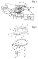
- This stud holder 2 comprises means 6 for fixing the stud holder 2 to an escape mechanism 30, such as a rocker cock, as visible on the figure 1 .
- the stud 1 comprises at least one lateral bearing surface 7 defining a direction of support or support of such a spiral spring 21,
- this stud holder 2 is in at least two parts, and comprises a rigid structure 5 carrying fastening means 6, and a spring blade 8 pressed against this rigid structure 5.
- This leaf spring 8 comprises at less an elastic lip 9 defining with the rigid structure 5 a receiving chamber 10 of the pin 1.
- This elastic lip 9 cooperates with this at least one lateral bearing surface 7 of the pin 1, for maintaining the pin 1 in the indexed position and blocking.
- the pin 1 is pinched between the elastic lip 9 of the leaf spring 8, and a notch 53 of the rigid structure 5, visible on the figure 2 .
- the lateral bearing surface 7 constitutes an orientation surface which defines a single direction of the outer end of the spiral spring 21.
- the leaf spring 8 illustrated in Figures 1, 2 and 3 is preferably sheet metal cut and folded, it does not require any other particular machining. It is inexpensive, which makes it possible to use, with the same carrying structure 31 of the exhaust mechanism 30, and with the same rigid structure 5, several spring blades 8 of different sizes to cooperate with so many models of pitons. different geometries.
- the rigid structure 5 may, depending on its dimensioning, be machined, or also made by stamping in a thicker and more rigid material than the spring blade 8.
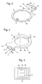
- the figure 2 shows a first variant of constant thickness, very economical, which lends itself to such a stamped embodiment.
- the figure 4 shows a second variant of rigid structure 5 on two levels, which is preferably machined.
- the assembly of the holding assembly 20 according to the invention makes it possible to simplify the machining and the production of the bolt carrier, since it is no longer necessary, contrary to the prior art, to make a bore or a housing similar for receiving the stud 1, nor tapping to cooperate with a locking screw.
- this at least one lateral bearing surface 7 is fitted to the stop surfaces 11, 12 to define a single position of the bolt 1 in the direction of the axis D of the spiral spring 21.
- the stud 1 has no stopping surface, on at least one side in the direction D.
- the rigid structure 5 and / or the leaf spring 8 comprises an introduction ramp 13, 14, for the tangential introduction (according to the arrow of the figure 1 ), or conversely the tangential extraction of the piton 1 between the rigid structure 5 and the leaf spring 8.
- This simple or compound ramp facilitates this insertion in the chamber 10 against the elastic return force of the spring blade 8. The same is true for the extraction.
- the pin 1 When the pin 1 is pressed against this ramp and the spring blade 8, it is easy to lift the elastic lip 9, to allow the pin to reach its position mounted in the chamber 10 delimited by a notch 15 forming a threshold. introduction or extraction.
- the chamber 10 is located, on the side of the leaf spring 8, in a clearance 80 visible on the figure 3 , the pin 1 bearing on a rear face 93 of the elastic lip 9, and, on the side of the rigid structure 5, in a notch 53.
- This notch 53 is delimited on the one hand by an input sector, of preferably radiated, constituting such a ramp 13, and secondly by a flat 51.
- This plate 51 may, according to the embodiment chosen, or remain at a distance from the elastic lip 9, or, as illustrated in FIG. figure 3 , bear in support a portion 94 of the elastic lip 9, only one end 95 cantilevered cooperating in support with the pin 1.
- Other variants are conceivable without departing from the invention, which consists in pinching the pin between a rigid structure and an elastic spring blade.
- the chamber 10 is designed, in all variants, to immobilize the stud 1 in a single position in projection in a plane perpendicular to the axis D.
- the rigid structure 5 and / or the leaf spring 8 comprises a notch 15 at the chamber 10, corresponding to the threshold of introduction or extraction.
- the rigid structure 5 comprises a notch 17 (or a slot, or the like) or a pin arranged to cooperate with a lug 18 or respectively a notch that comprises the spring-blade 8, to rigidly rotate the rigid structure 5 and the leaf-spring 8 pressed one on the other.
- the leaf spring may also comprise at least three tabs bent at 90 ° as the elastic blade 9, and located on a bore 81 or a peripheral rim 82 of the leaf spring 8, arranged to cooperate with a bore 58 or a peripheral rim 59 of the rigid structure 5, to ensure their perfectly coaxial assembly.
- the rigid structure 5 is of substantially annular shape for maintaining it resting on a structure 31, in particular a rocker arm, of the escapement mechanism 30, around the axis D of the spiral spring 21.
- the leaf spring 8 is substantially annular in shape for its support in abutment between such a structure 31 and the rigid structure 5, or in support of the rigid structure 5 over their entire common periphery, around the axis D of the coil spring 21.
- the rigid structure is mounted on the structure 31 so as to trap the leaf spring 8.
- the rigid structure 5 comprises at least one face 51, 52, perpendicular to the axis D of said spiral spring 21, and preferably this rigid structure 5 comprises two faces 51, 52 parallel to each other and perpendicular to the axis D of the spiral spring 21.
- the invention also relates to a clock escapement mechanism comprising at least one such holding assembly 20.
- the invention also relates to a watch movement 40 comprising at least one such exhaust mechanism 30.
Landscapes
- Physics & Mathematics (AREA)
- General Physics & Mathematics (AREA)
- Springs (AREA)
Abstract
Ensemble (20) de maintien d'un ressort-spiral (21) d'horlogerie, comportant un piton (1) et un porte-piton (2), lequel comporte des moyens de fixation (6) dudit porte-piton (2) à un mécanisme d'échappement (30), ledit piton (1) comportant une surface latérale d'appui (7) définissant une direction de maintien ou d'appui d'un dit ressort-spiral (21). Ledit porte-piton (2) est en deux parties, et comporte une structure rigide (5) porteuse desdits moyens de fixation (6), et une lame-ressort (8) plaquée contre ladite structure rigide (5) et comportant au moins une lèvre élastique (9) définissant avec ladite structure (5) une chambre (10) de réception dudit piton (1) et coopérant avec ladite surface latérale d'appui (7) dudit piton (1) pour le maintien dudit piton (1) en position indexée et de blocage.Assembly (20) for holding a clock spring (21) comprising a stud (1) and a stud holder (2), which comprises means (6) for fixing said stud holder (2) an escape mechanism (30), said peak (1) having a lateral bearing surface (7) defining a direction of support or support of said spiral spring (21). Said bolt carrier (2) is in two parts, and comprises a rigid structure (5) carrying said fastening means (6), and a leaf spring (8) pressed against said rigid structure (5) and comprising at least one elastic lip (9) defining with said structure (5) a chamber (10) for receiving said pin (1) and cooperating with said lateral bearing surface (7) of said pin (1) for maintaining said pin (1) in indexed and blocking position.
Description
L'invention concerne un ensemble de maintien ou d'appui d'un ressort spiral d'horlogerie, comportant un piton et un porte-piton, lequel porte-piton comporte des moyens de fixation dudit porte-piton à un mécanisme d'échappement, et ledit piton comportant au moins une surface d'orientation définissant une direction de maintien ou d'appui d'un dit ressort spiral.The invention relates to a holding or supporting assembly of a clockwork spiral spring, comprising a stud and a stud holder, which stud holder comprises means for fixing said stud holder to an escape mechanism, and said stud having at least one orientation surface defining a direction of support or support of said spiral spring.
L'invention concerne encore un mécanisme d'échappement d'horlogerie comportant au moins un tel ensemble de maintien.The invention also relates to a clock escapement mechanism comprising at least one such holding assembly.
L'invention concerne encore un mouvement d'horlogerie comportant au moins un tel mécanisme d'échappement.The invention also relates to a watch movement comprising at least one such escape mechanism.
L'invention concerne encore une pièce d'horlogerie comportant au moins un tel mouvement.The invention also relates to a timepiece comprising at least one such movement.
L'invention concerne le domaine des mécanismes d'échappement d'horlogerie.The invention relates to the field of watch exhaust mechanisms.
Sur de nombreux calibres de très grandes série, le piton, constituant le point d'attache externe du ressort-spiral, est clipé sur un porte-piton qui est une pièce plate étampée.On many calibres of very large series, the stud, constituting the external attachment point of the spiral spring, is clipped on a bolt carrier which is a stamped flat piece.
Sur des réalisations haut de gamme, le piton est vissé dans un porte-piton qui est un composant usiné. La vis de fixation travaille alors entre son pied et ses filets. La tête n'est jamais bloquée, ce qui entraîne des casses régulières, suite aux efforts de torsion subis lorsque le pied est bloqué sur le piton, et quand l'opérateur continue à visser.On high-end creations, the stud is screwed into a stud holder which is a machined component. The fixing screw then works between his foot and his nets. The head is never blocked, resulting in regular breakages, following the torsional forces experienced when the foot is blocked on the peak, and when the operator continues to screw.
L'invention se propose de fournir une solution de maintien de la spire externe du spiral, qui soit compatible avec des mouvements haut de gamme, et de résoudre le problème récurrent de tenue des vis par une solution de fixation exempte de vis.The invention proposes to provide a solution for maintaining the outer turn of the hairspring, which is compatible with high-end movements, and to solve the recurring problem of holding the screws by a screw-free fixing solution.
A cet effet, l'invention concerne un ensemble de maintien ou d'appui d'un ressort spiral d'horlogerie, comportant un piton et un porte-piton, lequel porte-piton comporte des moyens de fixation dudit porte-piton à un mécanisme d'échappement, ledit piton comportant au moins une surface d'orientation définissant une direction de maintien ou d'appui d'un dit ressort spiral, caractérisé en ce que ledit porte-piton est en deux parties, et comporte une structure rigide porteuse desdits moyens de fixation, et une lame-ressort plaquée contre ladite structure rigide et comportant au moins une lèvre élastique définissant avec ladite structure une chambre de réception dudit piton et coopérant avec ladite au moins une surface d'orientation dudit piton pour le maintien dudit piton en position indexée et de blocage.To this end, the invention relates to a holding or supporting assembly of a spiral clockwork spring, comprising a stud and a stud holder, which stud holder comprises means for fixing said stud holder to a mechanism exhaust, said peak having at least one orientation surface defining a direction of support or support of said spiral spring, characterized in that said bolt carrier is in two parts, and comprises a rigid structure carrying said fastening means, and a leaf-spring pressed against said rigid structure and comprising at least one elastic lip defining with said structure a receiving chamber of said pin and cooperating with said at least one orienting surface of said peak for maintaining said pin in indexed and blocking position.
Selon une caractéristique de l'invention, ladite surface latérale d'appui constitue une surface d'orientation qui définit une direction unique de l'extrémité externe dudit ressort spiral.According to a characteristic of the invention, said lateral bearing surface constitutes an orientation surface which defines a single direction of the outer end of said spiral spring.
L'invention concerne encore un mécanisme d'échappement d'horlogerie comportant au moins un tel ensemble de maintien.The invention also relates to a clock escapement mechanism comprising at least one such holding assembly.
L'invention concerne encore un mouvement d'horlogerie comportant au moins un tel mécanisme d'échappement.The invention also relates to a watch movement comprising at least one such escape mechanism.
L'invention concerne encore une pièce d'horlogerie comportant au moins un tel mouvement, caractérisée en ce que ladite pièce est une montre.The invention also relates to a timepiece comprising at least one such movement, characterized in that said piece is a watch.
D'autres caractéristiques et avantages de l'invention apparaîtront à la lecture de la description détaillée qui va suivre, en référence aux dessins annexés, où :
- la
figure 1 représente, de façon schématisée, partielle et en perspective, un mécanisme d'échappement comportant un ensemble de maintien de ressort-spiral selon l'invention, dans une position de présentation du piton, porteur de la spire externe du spiral, au niveau d'une section d'introduction de cet ensemble de maintien, qui est fixé sur une structure du mécanisme d'échappement telle un coq de balancier ; - la
figure 2 représente, de façon schématisée et en perspective éclatée, cet ensemble de maintien, comportant une structure rigide dans une première variante d'épaisseur constante, une lame-ressort, et le piton agencé pour coopérer avec cet ensemble ;
- la
figure 3 représente, de façon schématisée et en perspective, la lame-ressort de lafigure 2 ; - la
figure 4 représente, de façon schématisée et en perspective, une structure rigide dans une deuxième variante sur deux niveaux; - la
figure 5 est un schéma-blocs représentant une pièce d'horlogerie comportant un mouvement lequel comporte un mécanisme d'échappement incluant un ressort-spiral maintenu par un ensemble selon l'invention.
- the
figure 1 represents, schematically, partially and in perspective, an escapement mechanism comprising a spiral-spring holding assembly according to the invention, in a position of presentation of the stud, carrying the outer coil of the spiral, at the level of an introduction section of this holding assembly, which is fixed on a structure of the escapement mechanism such as a balance cock; - the
figure 2 represents, schematically and in exploded perspective, this holding assembly, comprising a rigid structure in a first constant thickness variant, a leaf-spring, and the piton arranged to cooperate with this set;
- the
figure 3 represents, schematically and in perspective, the leaf-spring of thefigure 2 ; - the
figure 4 schematically shows in perspective a rigid structure in a second variant on two levels; - the
figure 5 is a block diagram showing a timepiece comprising a movement which comprises an escapement mechanism including a spiral spring held by an assembly according to the invention.
Pour éliminer le maintien du piton par vis, l'invention recourt à un élément de fixation comportant des moyens de rappel élastique pour, d'une part autoriser l'introduction ou l'extraction d'un piton en exerçant sur lui un certain effort, et d'autre part maintenir ce piton en position de fonctionnement dans une position unique de butéeTo eliminate the maintenance of the bolt by screw, the invention makes use of a fastening element comprising elastic return means to, firstly allow the introduction or the extraction of a bolt by exerting on him a certain effort, and secondly maintain this pin in the operating position in a single stop position
L'invention concerne ainsi un ensemble 20 de maintien ou d'appui d'un ressort spiral 21 d'horlogerie, comportant un piton 1 et un porte-piton 2. Ce porte-piton 2 comporte des moyens de fixation 6 du porte-piton 2 à un mécanisme d'échappement 30, tel un coq de balancier, tel que visible sur la
Le piton 1 comporte au moins une surface latérale d'appui 7 définissant une direction de maintien ou d'appui d'un tel ressort spiral 21,The
Selon l'invention, ce porte-piton 2 est en au moins deux parties, et comporte une structure rigide 5 porteuse des moyens de fixation 6, et une lame-ressort 8 plaquée contre cette structure rigide 5. Cette lame-ressort 8 comporte au moins une lèvre élastique 9 définissant avec la structure rigide 5 une chambre 10 de réception du piton 1. Cette lèvre élastique 9 coopère avec cette au moins une surface latérale d'appui 7 du piton 1, pour le maintien du piton 1 en position indexée et de blocage. En somme, le piton 1 est pincé entre la lèvre élastique 9 de la lame-ressort 8, et une encoche 53 de la structure rigide 5, visible sur la
De préférence, la surface latérale d'appui 7 constitue une surface d'orientation qui définit une direction unique de l'extrémité externe du ressort spiral 21.Preferably, the lateral bearing
L'invention est illustrée dans une réalisation préférée où le porte-piton 2 est en deux parties, qui est économique car chacun des deux composants qu'il comporte est très simple à réaliser, et parfaitement compatible avec des tailles de séries importantes. Ce porte-piton 2 en deux parties, est, encore, d'un encombrement minimal. En effet, de préférence, et tel que visible sur les figures, la lame-ressort 8 enveloppe, au moins partiellement, la structure rigide 5, et l'encombrement total, selon la direction D de l'axe de pivotement du balancier, est le total entre l'épaisseur totale de la structure rigide 5, et l'épaisseur d'une feuille de tôle dans laquelle est préférentiellement formée la lame-ressort 8.The invention is illustrated in a preferred embodiment where the
La lame-ressort 8 illustrée en
La structure rigide 5 peut, selon son dimensionnement, être usinée, ou également réalisée par étampage dans un matériau plus épais et plus rigide que la lame-ressort 8. La
L'assemblage de l'ensemble de maintien 20 selon l'invention permet de simplifier l'usinage et la réalisation du porte-piton, car il n'est plus nécessaire, contrairement à l'art antérieur, de réaliser un alésage ou un logement similaire pour la réception du piton 1, ni de taraudage pour coopérer avec une vis de blocage.The assembly of the
Les variantes de réalisation, non limitatives, illustrées par les figures, autorisent une grande facilité d'assemblage, conjuguée à un bas coût de fabrication.The nonlimiting embodiments, illustrated by the figures, allow a great ease of assembly, combined with a low manufacturing cost.
De préférence, le piton 1 comporte, de part et d'autre de la au moins une surface latérale d'appui 7 qu'il comporte pour définir l'orientation de l'extrémité externe du spiral 21, des surfaces d'arrêt 11, 12, pour limiter le débattement de ce piton 1 selon la direction D de l'axe du ressort-spiral 21 par rapport à la pince constituée par l'ensemble de la structure rigide 5 et de la lame-ressort 8. Dans la variante illustrée, la lèvre élastique 9 de la lame-ressort 8 a deux surfaces de bord 91 et 92 qui sont parallèles (et situées chacune dans un plan perpendiculaire à la direction D) et coopère avec cette surface latérale d'appui 7, qui est ici constituée par un plat 16, délimité par ces surfaces d'arrêt 11 et 12. De façon préférée, dans les différentes variantes présentées, la surface latérale d'appui 7 est un plat 16 parallèle à l'axe D du ressort-spiral 21.Preferably, the
Dans une version indéréglable, on peut définir l'écart E1 entre les surfaces d'arrêt 11 et 12 égal à l'écart E entre ces surfaces d'arrêt 11 et 12 pour un maintien sans jeu axial. Ainsi, dans cette version indéréglable, cette au moins une surface latérale d'appui 7 est ajustée aux surfaces d'arrêt 11, 12, pour définir une position unique du piton 1 selon la direction de l'axe D du ressort-spiral 21.In a foolproof version, it is possible to define the distance E1 between the
Dans une autre variante, on peut laisser un certain jeu autorisant un réglage axial limité du piton 1, en choisissant l'écart E1 supérieur à l'écart E, de la valeur de la plage de réglage souhaitée.In another variant, it is possible to leave a certain clearance allowing a limited axial adjustment of the
Dans une autre variante encore, le piton 1 ne comporte pas de surface d'arrêt, sur au moins un côté selon la direction D.In another variant, the
Pour faciliter l'introduction ou l'extraction du piton 1 par rapport à cet ensemble de maintien 20, la structure rigide 5 ou/et la lame-ressort 8 comporte une rampe d'introduction 13, 14, pour l'introduction tangentielle (selon la flèche de la
Sur les variantes illustrées, la chambre 10 se situe, du côté de la lame-ressort 8, dans un dégagement 80 visible sur la
La chambre 10 est conçue, dans toutes les variantes, pour immobiliser le piton 1 dans une position unique en projection dans un plan perpendiculaire à l'axe D.The
De préférence, la structure rigide 5 ou/et la lame-ressort 8 comporte un cran 15 au niveau de la chambre 10, correspondant au seuil d'introduction ou d'extraction.Preferably, the
Pour le positionnement relatif optimal entre la structure rigide 5 et la lame-ressort 8, dans une réalisation avantageuse illustrée sur les figures, la structure rigide 5 comporte une encoche 17 (ou une fente, ou similaire) ou un ergot agencé pour coopérer avec un ergot 18 ou respectivement une encoche que comporte la lame-ressort 8, pour solidariser en rotation la structure rigide 5 et la lame-ressort 8 plaquées l'une sur l'autre. Dans une variante non illustrée, la lame-ressort peut aussi comporter au moins trois pattes pliées à 90° comme la lame élastique 9, et situées sur un alésage 81 ou un rebord périphérique 82 de la lame-ressort 8, agencées pour coopérer avec un alésage 58 ou un rebord périphérique 59 de la structure rigide 5, pour assurer leur assemblage parfaitement coaxial.For the optimal relative positioning between the
Ce positionnement relatif permet de synchroniser la structure rigide 5 et la lame-ressort 8, soit pendant leur assemblage, soit dans une phase de réglage si l'on décide de laisser une mobilité angulaire restreinte à l'ensemble de maintien 20 pour effectuer un réglage angulaire de position du piton 1. Naturellement, le mécanisme nécessite alors au moins des moyens de maintien en position de cet ensemble 20 par rapport à la structure 31.This relative positioning makes it possible to synchronize the
De préférence, la structure rigide 5 est de forme sensiblement annulaire pour son maintien en appui sur une structure 31, notamment un coq de balancier, du mécanisme d'échappement 30, autour de l'axe D du ressort-spiral 21.Preferably, the
De préférence, la lame-ressort 8 est de forme sensiblement annulaire pour son maintien en appui entre une telle structure 31 et la structure rigide 5, ou bien en appui sur la structure rigide 5 sur toute leur périphérie commune, autour de l'axe D du ressort-spiral 21. Avantageusement, la structure rigide est montée sur la structure 31 de façon à emprisonner la lame-ressort 8.Preferably, the
Dans une exécution économique, la structure rigide 5 comporte au moins une face 51, 52, perpendiculaire à l'axe D dudit ressort-spiral 21, et, de préférence cette structure rigide 5 comporte deux faces 51, 52, parallèles entre elles et perpendiculaires à l'axe D du ressort-spiral 21.In an economical embodiment, the
Le cas particulier de la structure rigide 5 sur deux niveaux de la
L'invention concerne encore un mécanisme d'échappement 30 d'horlogerie comportant au moins un tel ensemble de maintien 20.The invention also relates to a clock escapement mechanism comprising at least one such holding
L'invention concerne encore un mouvement d'horlogerie 40 comportant au moins un tel mécanisme d'échappement 30.The invention also relates to a
L'invention concerne encore une pièce d'horlogerie 50 comportant au moins un tel mouvement 40. Plus particulièrement, cette pièce 50 est une montre. En somme, l'invention apporte divers avantages :
- la vis d'un porte-piton traditionnel à vis est remplacée par un composant découpé, peu coûteux ;
- l'usinage de la structure rigide formant porte-piton est fortement simplifié, voire remplacé par un étampage ;
- le mécanisme est d'un niveau esthétique et de qualité compatible avec des mouvements horlogers de haut de gamme ;
- un réglage axial du piton reste possible ;
- le mécanisme selon l'invention est interchangeable, dans un mouvement existant, avec un porte-piton traditionnel.
- the screw of a traditional screw bolt carrier is replaced by a cut component, inexpensive;
- the machining of the rigid structure forming bolt carrier is greatly simplified, or even replaced by a stamping;
- the mechanism is of an aesthetic level and quality compatible with high-end watch movements;
- an axial adjustment of the piton remains possible;
- the mechanism according to the invention is interchangeable, in an existing movement, with a traditional bolt carrier.
Claims (15)
Priority Applications (6)
| Application Number | Priority Date | Filing Date | Title |
|---|---|---|---|
| EP13193609.8A EP2876504B1 (en) | 2013-11-20 | 2013-11-20 | Screwless clock stud holder |
| US14/519,293 US9176475B2 (en) | 2013-11-20 | 2014-10-21 | Timepiece balance spring stud-holder with no screws |
| JP2014231286A JP5938087B2 (en) | 2013-11-20 | 2014-11-14 | Balance spring stud holder for timers without screws |
| CN201420702979.2U CN204331292U (en) | 2013-11-20 | 2014-11-20 | For keeping or support the assembly of clock watch balance spring, timepiece escapement, watch and clock movement and clock and watch |
| CN201410670387.1A CN104656407B (en) | 2013-11-20 | 2014-11-20 | Clock watch balance spring stud keeper without screw |
| HK15110064.3A HK1209497A1 (en) | 2013-11-20 | 2015-10-14 | Timepiece balance spring stud-holder with no screws |
Applications Claiming Priority (1)
| Application Number | Priority Date | Filing Date | Title |
|---|---|---|---|
| EP13193609.8A EP2876504B1 (en) | 2013-11-20 | 2013-11-20 | Screwless clock stud holder |
Publications (2)
| Publication Number | Publication Date |
|---|---|
| EP2876504A1 true EP2876504A1 (en) | 2015-05-27 |
| EP2876504B1 EP2876504B1 (en) | 2017-07-26 |
Family
ID=49596174
Family Applications (1)
| Application Number | Title | Priority Date | Filing Date |
|---|---|---|---|
| EP13193609.8A Active EP2876504B1 (en) | 2013-11-20 | 2013-11-20 | Screwless clock stud holder |
Country Status (5)
| Country | Link |
|---|---|
| US (1) | US9176475B2 (en) |
| EP (1) | EP2876504B1 (en) |
| JP (1) | JP5938087B2 (en) |
| CN (2) | CN204331292U (en) |
| HK (1) | HK1209497A1 (en) |
Cited By (4)
| Publication number | Priority date | Publication date | Assignee | Title |
|---|---|---|---|---|
| EP3451076A1 (en) | 2017-08-31 | 2019-03-06 | ETA SA Manufacture Horlogère Suisse | Stud-holder for a mechanical clockwork movement |
| EP3179315B1 (en) * | 2015-12-11 | 2019-03-27 | ETA SA Manufacture Horlogère Suisse | Stud support with secure mounting |
| EP4286962A1 (en) | 2022-06-02 | 2023-12-06 | ETA SA Manufacture Horlogère Suisse | Timepiece regulating member comprising a regulator assembly provided with locking means |
| EP4286960A1 (en) | 2022-06-02 | 2023-12-06 | ETA SA Manufacture Horlogère Suisse | Timepiece regulator provided with an index-assembly system |
Families Citing this family (11)
| Publication number | Priority date | Publication date | Assignee | Title |
|---|---|---|---|---|
| EP2876504B1 (en) * | 2013-11-20 | 2017-07-26 | ETA SA Manufacture Horlogère Suisse | Screwless clock stud holder |
| EP3032353B1 (en) * | 2014-12-11 | 2019-08-07 | ETA SA Manufacture Horlogère Suisse | Detachable stud support |
| EP3037896B1 (en) * | 2014-12-22 | 2017-05-10 | ETA SA Manufacture Horlogère Suisse | Detachable stud support |
| EP3179314B1 (en) * | 2015-12-11 | 2018-11-14 | ETA SA Manufacture Horlogère Suisse | Stud support with simplified assembly |
| EP3211486B1 (en) * | 2016-02-25 | 2018-09-26 | ETA SA Manufacture Horlogère Suisse | Method for attaching a hairspring for mechanical clock movement |
| FR3052881B1 (en) * | 2016-06-21 | 2020-10-02 | Lvmh Swiss Mft Sa | PART FOR CLOCK MOVEMENT, CLOCK MOVEMENT, CLOCK PART AND PROCESS FOR MANUFACTURING SUCH A PART FOR CLOCK MOVEMENT |
| EP3273310A1 (en) * | 2016-07-20 | 2018-01-24 | ETA SA Manufacture Horlogère Suisse | Regulator key |
| EP3627238A1 (en) * | 2018-09-21 | 2020-03-25 | Nivarox-FAR S.A. | Elastic holding member for fixing a timepiece component on a support element |
| EP3627234A1 (en) * | 2018-09-21 | 2020-03-25 | Nivarox-FAR S.A. | Elastic holding member for fixing a timepiece component on a support element |
| EP3779607A1 (en) * | 2019-08-16 | 2021-02-17 | Nivarox-FAR S.A. | Method for carrying out the assembly of a set comprising an elastic holding element - timepiece component with a support element |
| EP4006649A1 (en) * | 2020-11-27 | 2022-06-01 | ETA SA Manufacture Horlogère Suisse | Attachment device for adjusting the movement of a balance |
Citations (2)
| Publication number | Priority date | Publication date | Assignee | Title |
|---|---|---|---|---|
| CH332548A (en) * | 1957-06-13 | 1958-09-15 | Parechoc Sa | Rack for timepieces |
| EP2290477A1 (en) * | 2009-08-25 | 2011-03-02 | Glashütter Uhrenbetrieb GmbH | Assembly for fixing the peripheral end of the hairspring of a device with balance wheel-hairspring for a timepiece |
Family Cites Families (15)
| Publication number | Priority date | Publication date | Assignee | Title |
|---|---|---|---|---|
| US221180A (en) * | 1879-08-19 | 1879-11-04 | Improvement in hair-spring studs | |
| US440877A (en) * | 1890-02-07 | 1890-11-18 | Botham | |
| US1181510A (en) * | 1914-01-16 | 1916-05-02 | Robt H Ingersoll & Bro | Hair-spring compensator and regulator for watches. |
| CH76336A (en) * | 1917-07-16 | 1917-12-01 | Edouard Glauser | Spiral-holder eyebolt fixing device |
| US3046725A (en) * | 1958-10-29 | 1962-07-31 | Parechoc Sa | Hairspring adjustment device for a timepiece |
| JPS509027Y1 (en) * | 1970-07-27 | 1975-03-18 | ||
| CH1622873A4 (en) * | 1973-01-11 | 1976-03-31 | ||
| JPS5288061A (en) * | 1976-01-16 | 1977-07-22 | Seiko Epson Corp | Outer end fixing structure for balance springs |
| CN2149644Y (en) * | 1992-10-29 | 1993-12-15 | 大连手表工业公司 | Mechanism for fixing stud of a wrist watch |
| CH692532A5 (en) * | 1997-10-21 | 2002-07-15 | Ebauchesfabrik Eta Ag | A method of making a balance spring for a horological movement. |
| CN1154026C (en) * | 1999-07-29 | 2004-06-16 | 精工电子有限公司 | Mechanical timepiece with stud adjustment mechanism |
| DE10345918A1 (en) * | 2003-10-02 | 2005-05-12 | Lange Uhren Gmbh | oscillating system |
| CN201532534U (en) * | 2009-10-27 | 2010-07-21 | 天津海鸥表业集团有限公司 | Fixed structure of watch hairspring stud |
| EP2570871B1 (en) * | 2011-09-14 | 2014-03-19 | Montres Breguet SA | Hairspring with two spiral springs |
| EP2876504B1 (en) * | 2013-11-20 | 2017-07-26 | ETA SA Manufacture Horlogère Suisse | Screwless clock stud holder |
-
2013
- 2013-11-20 EP EP13193609.8A patent/EP2876504B1/en active Active
-
2014
- 2014-10-21 US US14/519,293 patent/US9176475B2/en active Active
- 2014-11-14 JP JP2014231286A patent/JP5938087B2/en active Active
- 2014-11-20 CN CN201420702979.2U patent/CN204331292U/en not_active Withdrawn - After Issue
- 2014-11-20 CN CN201410670387.1A patent/CN104656407B/en active Active
-
2015
- 2015-10-14 HK HK15110064.3A patent/HK1209497A1/en unknown
Patent Citations (2)
| Publication number | Priority date | Publication date | Assignee | Title |
|---|---|---|---|---|
| CH332548A (en) * | 1957-06-13 | 1958-09-15 | Parechoc Sa | Rack for timepieces |
| EP2290477A1 (en) * | 2009-08-25 | 2011-03-02 | Glashütter Uhrenbetrieb GmbH | Assembly for fixing the peripheral end of the hairspring of a device with balance wheel-hairspring for a timepiece |
Cited By (5)
| Publication number | Priority date | Publication date | Assignee | Title |
|---|---|---|---|---|
| EP3179315B1 (en) * | 2015-12-11 | 2019-03-27 | ETA SA Manufacture Horlogère Suisse | Stud support with secure mounting |
| EP3451076A1 (en) | 2017-08-31 | 2019-03-06 | ETA SA Manufacture Horlogère Suisse | Stud-holder for a mechanical clockwork movement |
| EP4286962A1 (en) | 2022-06-02 | 2023-12-06 | ETA SA Manufacture Horlogère Suisse | Timepiece regulating member comprising a regulator assembly provided with locking means |
| EP4286960A1 (en) | 2022-06-02 | 2023-12-06 | ETA SA Manufacture Horlogère Suisse | Timepiece regulator provided with an index-assembly system |
| EP4286961A1 (en) | 2022-06-02 | 2023-12-06 | Omega SA | Timepiece regulator provided with a precision index-assembly |
Also Published As
| Publication number | Publication date |
|---|---|
| JP2015102550A (en) | 2015-06-04 |
| CN104656407B (en) | 2017-10-03 |
| JP5938087B2 (en) | 2016-06-22 |
| HK1209497A1 (en) | 2016-04-01 |
| US9176475B2 (en) | 2015-11-03 |
| CN204331292U (en) | 2015-05-13 |
| US20150138934A1 (en) | 2015-05-21 |
| CN104656407A (en) | 2015-05-27 |
| EP2876504B1 (en) | 2017-07-26 |
Similar Documents
| Publication | Publication Date | Title |
|---|---|---|
| EP2876504B1 (en) | Screwless clock stud holder | |
| EP2887154B1 (en) | Mechanism for attaching a balance-spring stud to a balance bridge and regulating device with balance-hairspring including such a mechanism | |
| EP2804055B1 (en) | Assembly consisting of a stud and a stud support | |
| EP3502788A1 (en) | Standalone device for adjusting the active length of a hairspring | |
| EP1515200A1 (en) | Hairspring for timepiece | |
| EP2824518B1 (en) | Micrometric adjustment of the shake of a clock mobile | |
| EP3869280A1 (en) | Timepiece display mechanism | |
| EP3432081B1 (en) | Timepiece assembly | |
| EP3037896B1 (en) | Detachable stud support | |
| EP2876505B1 (en) | Clock stud holder with screw | |
| EP3985450B1 (en) | Device for locking a movement of a clock piece | |
| CH708878A2 (en) | Together with a peak and a clock gate stud. | |
| EP3163384B1 (en) | Flexible pivoting guide of a clock mobile | |
| EP3037895B1 (en) | Detachable stud support | |
| CH706108B1 (en) | Simplified stop-seconds device for watch movement. | |
| CH707925A1 (en) | mechanical oscillator for clock movement. | |
| EP3470932B1 (en) | Oscillator for a timepiece movement | |
| CH714249A1 (en) | Oscillator for watch movement. | |
| CH710551A2 (en) | Holding assembly or support of a timepiece balance spring with a peak and a carrier peak. | |
| EP4123391A1 (en) | Timepiece component to be attached to a shaft and its assembly process | |
| CH717975A2 (en) | Casing circle. | |
| CH716487A2 (en) | Clock indexing element. | |
| CH710894A2 (en) | time base for the clock movement. | |
| CH708880A2 (en) | Together with a clock and a door bolt stud screw. | |
| CH697211A5 (en) | Portable electronic apparatus e.g. wristwatch, has cams for displacing display unit against support surfaces of support piece and transforming rotational movement into translational movement, where support piece receives display unit |
Legal Events
| Date | Code | Title | Description |
|---|---|---|---|
| PUAI | Public reference made under article 153(3) epc to a published international application that has entered the european phase |
Free format text: ORIGINAL CODE: 0009012 |
|
| 17P | Request for examination filed |
Effective date: 20131120 |
|
| AK | Designated contracting states |
Kind code of ref document: A1 Designated state(s): AL AT BE BG CH CY CZ DE DK EE ES FI FR GB GR HR HU IE IS IT LI LT LU LV MC MK MT NL NO PL PT RO RS SE SI SK SM TR |
|
| AX | Request for extension of the european patent |
Extension state: BA ME |
|
| R17P | Request for examination filed (corrected) |
Effective date: 20151127 |
|
| RBV | Designated contracting states (corrected) |
Designated state(s): AL AT BE BG CH CY CZ DE DK EE ES FI FR GB GR HR HU IE IS IT LI LT LU LV MC MK MT NL NO PL PT RO RS SE SI SK SM TR |
|
| GRAP | Despatch of communication of intention to grant a patent |
Free format text: ORIGINAL CODE: EPIDOSNIGR1 |
|
| INTG | Intention to grant announced |
Effective date: 20170508 |
|
| GRAS | Grant fee paid |
Free format text: ORIGINAL CODE: EPIDOSNIGR3 |
|
| GRAA | (expected) grant |
Free format text: ORIGINAL CODE: 0009210 |
|
| AK | Designated contracting states |
Kind code of ref document: B1 Designated state(s): AL AT BE BG CH CY CZ DE DK EE ES FI FR GB GR HR HU IE IS IT LI LT LU LV MC MK MT NL NO PL PT RO RS SE SI SK SM TR |
|
| REG | Reference to a national code |
Ref country code: GB Ref legal event code: FG4D Free format text: NOT ENGLISH |
|
| REG | Reference to a national code |
Ref country code: CH Ref legal event code: EP |
|
| REG | Reference to a national code |
Ref country code: AT Ref legal event code: REF Ref document number: 912864 Country of ref document: AT Kind code of ref document: T Effective date: 20170815 |
|
| REG | Reference to a national code |
Ref country code: IE Ref legal event code: FG4D Free format text: LANGUAGE OF EP DOCUMENT: FRENCH |
|
| REG | Reference to a national code |
Ref country code: CH Ref legal event code: NV Representative=s name: ICB INGENIEURS CONSEILS EN BREVETS SA, CH |
|
| REG | Reference to a national code |
Ref country code: DE Ref legal event code: R096 Ref document number: 602013023973 Country of ref document: DE |
|
| REG | Reference to a national code |
Ref country code: FR Ref legal event code: PLFP Year of fee payment: 5 |
|
| REG | Reference to a national code |
Ref country code: NL Ref legal event code: MP Effective date: 20170726 |
|
| REG | Reference to a national code |
Ref country code: LT Ref legal event code: MG4D |
|
| REG | Reference to a national code |
Ref country code: AT Ref legal event code: MK05 Ref document number: 912864 Country of ref document: AT Kind code of ref document: T Effective date: 20170726 |
|
| PG25 | Lapsed in a contracting state [announced via postgrant information from national office to epo] |
Ref country code: NL Free format text: LAPSE BECAUSE OF FAILURE TO SUBMIT A TRANSLATION OF THE DESCRIPTION OR TO PAY THE FEE WITHIN THE PRESCRIBED TIME-LIMIT Effective date: 20170726 Ref country code: NO Free format text: LAPSE BECAUSE OF FAILURE TO SUBMIT A TRANSLATION OF THE DESCRIPTION OR TO PAY THE FEE WITHIN THE PRESCRIBED TIME-LIMIT Effective date: 20171026 Ref country code: AT Free format text: LAPSE BECAUSE OF FAILURE TO SUBMIT A TRANSLATION OF THE DESCRIPTION OR TO PAY THE FEE WITHIN THE PRESCRIBED TIME-LIMIT Effective date: 20170726 Ref country code: SE Free format text: LAPSE BECAUSE OF FAILURE TO SUBMIT A TRANSLATION OF THE DESCRIPTION OR TO PAY THE FEE WITHIN THE PRESCRIBED TIME-LIMIT Effective date: 20170726 Ref country code: FI Free format text: LAPSE BECAUSE OF FAILURE TO SUBMIT A TRANSLATION OF THE DESCRIPTION OR TO PAY THE FEE WITHIN THE PRESCRIBED TIME-LIMIT Effective date: 20170726 Ref country code: HR Free format text: LAPSE BECAUSE OF FAILURE TO SUBMIT A TRANSLATION OF THE DESCRIPTION OR TO PAY THE FEE WITHIN THE PRESCRIBED TIME-LIMIT Effective date: 20170726 Ref country code: LT Free format text: LAPSE BECAUSE OF FAILURE TO SUBMIT A TRANSLATION OF THE DESCRIPTION OR TO PAY THE FEE WITHIN THE PRESCRIBED TIME-LIMIT Effective date: 20170726 |
|
| PG25 | Lapsed in a contracting state [announced via postgrant information from national office to epo] |
Ref country code: IS Free format text: LAPSE BECAUSE OF FAILURE TO SUBMIT A TRANSLATION OF THE DESCRIPTION OR TO PAY THE FEE WITHIN THE PRESCRIBED TIME-LIMIT Effective date: 20171126 Ref country code: LV Free format text: LAPSE BECAUSE OF FAILURE TO SUBMIT A TRANSLATION OF THE DESCRIPTION OR TO PAY THE FEE WITHIN THE PRESCRIBED TIME-LIMIT Effective date: 20170726 Ref country code: BG Free format text: LAPSE BECAUSE OF FAILURE TO SUBMIT A TRANSLATION OF THE DESCRIPTION OR TO PAY THE FEE WITHIN THE PRESCRIBED TIME-LIMIT Effective date: 20171026 Ref country code: GR Free format text: LAPSE BECAUSE OF FAILURE TO SUBMIT A TRANSLATION OF THE DESCRIPTION OR TO PAY THE FEE WITHIN THE PRESCRIBED TIME-LIMIT Effective date: 20171027 Ref country code: RS Free format text: LAPSE BECAUSE OF FAILURE TO SUBMIT A TRANSLATION OF THE DESCRIPTION OR TO PAY THE FEE WITHIN THE PRESCRIBED TIME-LIMIT Effective date: 20170726 Ref country code: ES Free format text: LAPSE BECAUSE OF FAILURE TO SUBMIT A TRANSLATION OF THE DESCRIPTION OR TO PAY THE FEE WITHIN THE PRESCRIBED TIME-LIMIT Effective date: 20170726 Ref country code: PL Free format text: LAPSE BECAUSE OF FAILURE TO SUBMIT A TRANSLATION OF THE DESCRIPTION OR TO PAY THE FEE WITHIN THE PRESCRIBED TIME-LIMIT Effective date: 20170726 |
|
| PG25 | Lapsed in a contracting state [announced via postgrant information from national office to epo] |
Ref country code: DK Free format text: LAPSE BECAUSE OF FAILURE TO SUBMIT A TRANSLATION OF THE DESCRIPTION OR TO PAY THE FEE WITHIN THE PRESCRIBED TIME-LIMIT Effective date: 20170726 Ref country code: RO Free format text: LAPSE BECAUSE OF FAILURE TO SUBMIT A TRANSLATION OF THE DESCRIPTION OR TO PAY THE FEE WITHIN THE PRESCRIBED TIME-LIMIT Effective date: 20170726 Ref country code: CZ Free format text: LAPSE BECAUSE OF FAILURE TO SUBMIT A TRANSLATION OF THE DESCRIPTION OR TO PAY THE FEE WITHIN THE PRESCRIBED TIME-LIMIT Effective date: 20170726 |
|
| REG | Reference to a national code |
Ref country code: DE Ref legal event code: R097 Ref document number: 602013023973 Country of ref document: DE |
|
| PG25 | Lapsed in a contracting state [announced via postgrant information from national office to epo] |
Ref country code: SM Free format text: LAPSE BECAUSE OF FAILURE TO SUBMIT A TRANSLATION OF THE DESCRIPTION OR TO PAY THE FEE WITHIN THE PRESCRIBED TIME-LIMIT Effective date: 20170726 Ref country code: IT Free format text: LAPSE BECAUSE OF FAILURE TO SUBMIT A TRANSLATION OF THE DESCRIPTION OR TO PAY THE FEE WITHIN THE PRESCRIBED TIME-LIMIT Effective date: 20170726 Ref country code: SK Free format text: LAPSE BECAUSE OF FAILURE TO SUBMIT A TRANSLATION OF THE DESCRIPTION OR TO PAY THE FEE WITHIN THE PRESCRIBED TIME-LIMIT Effective date: 20170726 Ref country code: EE Free format text: LAPSE BECAUSE OF FAILURE TO SUBMIT A TRANSLATION OF THE DESCRIPTION OR TO PAY THE FEE WITHIN THE PRESCRIBED TIME-LIMIT Effective date: 20170726 |
|
| PLBE | No opposition filed within time limit |
Free format text: ORIGINAL CODE: 0009261 |
|
| STAA | Information on the status of an ep patent application or granted ep patent |
Free format text: STATUS: NO OPPOSITION FILED WITHIN TIME LIMIT |
|
| PG25 | Lapsed in a contracting state [announced via postgrant information from national office to epo] |
Ref country code: MC Free format text: LAPSE BECAUSE OF FAILURE TO SUBMIT A TRANSLATION OF THE DESCRIPTION OR TO PAY THE FEE WITHIN THE PRESCRIBED TIME-LIMIT Effective date: 20170726 |
|
| 26N | No opposition filed |
Effective date: 20180430 |
|
| GBPC | Gb: european patent ceased through non-payment of renewal fee |
Effective date: 20171120 |
|
| PG25 | Lapsed in a contracting state [announced via postgrant information from national office to epo] |
Ref country code: SI Free format text: LAPSE BECAUSE OF FAILURE TO SUBMIT A TRANSLATION OF THE DESCRIPTION OR TO PAY THE FEE WITHIN THE PRESCRIBED TIME-LIMIT Effective date: 20170726 Ref country code: LU Free format text: LAPSE BECAUSE OF NON-PAYMENT OF DUE FEES Effective date: 20171120 |
|
| REG | Reference to a national code |
Ref country code: BE Ref legal event code: MM Effective date: 20171130 |
|
| REG | Reference to a national code |
Ref country code: IE Ref legal event code: MM4A |
|
| PG25 | Lapsed in a contracting state [announced via postgrant information from national office to epo] |
Ref country code: MT Free format text: LAPSE BECAUSE OF FAILURE TO SUBMIT A TRANSLATION OF THE DESCRIPTION OR TO PAY THE FEE WITHIN THE PRESCRIBED TIME-LIMIT Effective date: 20170726 |
|
| REG | Reference to a national code |
Ref country code: FR Ref legal event code: PLFP Year of fee payment: 6 |
|
| PG25 | Lapsed in a contracting state [announced via postgrant information from national office to epo] |
Ref country code: IE Free format text: LAPSE BECAUSE OF NON-PAYMENT OF DUE FEES Effective date: 20171120 |
|
| PG25 | Lapsed in a contracting state [announced via postgrant information from national office to epo] |
Ref country code: BE Free format text: LAPSE BECAUSE OF NON-PAYMENT OF DUE FEES Effective date: 20171130 Ref country code: GB Free format text: LAPSE BECAUSE OF NON-PAYMENT OF DUE FEES Effective date: 20171120 |
|
| PG25 | Lapsed in a contracting state [announced via postgrant information from national office to epo] |
Ref country code: HU Free format text: LAPSE BECAUSE OF FAILURE TO SUBMIT A TRANSLATION OF THE DESCRIPTION OR TO PAY THE FEE WITHIN THE PRESCRIBED TIME-LIMIT; INVALID AB INITIO Effective date: 20131120 |
|
| PG25 | Lapsed in a contracting state [announced via postgrant information from national office to epo] |
Ref country code: CY Free format text: LAPSE BECAUSE OF FAILURE TO SUBMIT A TRANSLATION OF THE DESCRIPTION OR TO PAY THE FEE WITHIN THE PRESCRIBED TIME-LIMIT Effective date: 20170726 |
|
| PG25 | Lapsed in a contracting state [announced via postgrant information from national office to epo] |
Ref country code: MK Free format text: LAPSE BECAUSE OF FAILURE TO SUBMIT A TRANSLATION OF THE DESCRIPTION OR TO PAY THE FEE WITHIN THE PRESCRIBED TIME-LIMIT Effective date: 20170726 |
|
| PG25 | Lapsed in a contracting state [announced via postgrant information from national office to epo] |
Ref country code: TR Free format text: LAPSE BECAUSE OF FAILURE TO SUBMIT A TRANSLATION OF THE DESCRIPTION OR TO PAY THE FEE WITHIN THE PRESCRIBED TIME-LIMIT Effective date: 20170726 |
|
| PG25 | Lapsed in a contracting state [announced via postgrant information from national office to epo] |
Ref country code: PT Free format text: LAPSE BECAUSE OF FAILURE TO SUBMIT A TRANSLATION OF THE DESCRIPTION OR TO PAY THE FEE WITHIN THE PRESCRIBED TIME-LIMIT Effective date: 20170726 |
|
| PG25 | Lapsed in a contracting state [announced via postgrant information from national office to epo] |
Ref country code: AL Free format text: LAPSE BECAUSE OF FAILURE TO SUBMIT A TRANSLATION OF THE DESCRIPTION OR TO PAY THE FEE WITHIN THE PRESCRIBED TIME-LIMIT Effective date: 20170726 |
|
| P01 | Opt-out of the competence of the unified patent court (upc) registered |
Effective date: 20230701 |
|
| PGFP | Annual fee paid to national office [announced via postgrant information from national office to epo] |
Ref country code: FR Payment date: 20231019 Year of fee payment: 11 Ref country code: DE Payment date: 20231019 Year of fee payment: 11 Ref country code: CH Payment date: 20231201 Year of fee payment: 11 |