EP2876293A2 - Tank module for a liquid tank - Google Patents
Tank module for a liquid tank Download PDFInfo
- Publication number
- EP2876293A2 EP2876293A2 EP14194310.0A EP14194310A EP2876293A2 EP 2876293 A2 EP2876293 A2 EP 2876293A2 EP 14194310 A EP14194310 A EP 14194310A EP 2876293 A2 EP2876293 A2 EP 2876293A2
- Authority
- EP
- European Patent Office
- Prior art keywords
- heating
- liquid
- tank module
- tank
- heating elements
- Prior art date
- Legal status (The legal status is an assumption and is not a legal conclusion. Google has not performed a legal analysis and makes no representation as to the accuracy of the status listed.)
- Withdrawn
Links
Images


Classifications
-
- H—ELECTRICITY
- H05—ELECTRIC TECHNIQUES NOT OTHERWISE PROVIDED FOR
- H05B—ELECTRIC HEATING; ELECTRIC LIGHT SOURCES NOT OTHERWISE PROVIDED FOR; CIRCUIT ARRANGEMENTS FOR ELECTRIC LIGHT SOURCES, IN GENERAL
- H05B1/00—Details of electric heating devices
- H05B1/02—Automatic switching arrangements specially adapted to apparatus ; Control of heating devices
- H05B1/0227—Applications
- H05B1/023—Industrial applications
- H05B1/0244—Heating of fluids
-
- B—PERFORMING OPERATIONS; TRANSPORTING
- B60—VEHICLES IN GENERAL
- B60K—ARRANGEMENT OR MOUNTING OF PROPULSION UNITS OR OF TRANSMISSIONS IN VEHICLES; ARRANGEMENT OR MOUNTING OF PLURAL DIVERSE PRIME-MOVERS IN VEHICLES; AUXILIARY DRIVES FOR VEHICLES; INSTRUMENTATION OR DASHBOARDS FOR VEHICLES; ARRANGEMENTS IN CONNECTION WITH COOLING, AIR INTAKE, GAS EXHAUST OR FUEL SUPPLY OF PROPULSION UNITS IN VEHICLES
- B60K15/00—Arrangement in connection with fuel supply of combustion engines or other fuel consuming energy converters, e.g. fuel cells; Mounting or construction of fuel tanks
- B60K15/03—Fuel tanks
- B60K2015/03328—Arrangements or special measures related to fuel tanks or fuel handling
- B60K2015/03427—Arrangements or special measures related to fuel tanks or fuel handling for heating fuel, e.g. to avoiding freezing
-
- F—MECHANICAL ENGINEERING; LIGHTING; HEATING; WEAPONS; BLASTING
- F01—MACHINES OR ENGINES IN GENERAL; ENGINE PLANTS IN GENERAL; STEAM ENGINES
- F01N—GAS-FLOW SILENCERS OR EXHAUST APPARATUS FOR MACHINES OR ENGINES IN GENERAL; GAS-FLOW SILENCERS OR EXHAUST APPARATUS FOR INTERNAL-COMBUSTION ENGINES
- F01N2560/00—Exhaust systems with means for detecting or measuring exhaust gas components or characteristics
- F01N2560/06—Exhaust systems with means for detecting or measuring exhaust gas components or characteristics the means being a temperature sensor
-
- F—MECHANICAL ENGINEERING; LIGHTING; HEATING; WEAPONS; BLASTING
- F01—MACHINES OR ENGINES IN GENERAL; ENGINE PLANTS IN GENERAL; STEAM ENGINES
- F01N—GAS-FLOW SILENCERS OR EXHAUST APPARATUS FOR MACHINES OR ENGINES IN GENERAL; GAS-FLOW SILENCERS OR EXHAUST APPARATUS FOR INTERNAL-COMBUSTION ENGINES
- F01N2610/00—Adding substances to exhaust gases
- F01N2610/10—Adding substances to exhaust gases the substance being heated, e.g. by heating tank or supply line of the added substance
- F01N2610/105—Control thereof
-
- F—MECHANICAL ENGINEERING; LIGHTING; HEATING; WEAPONS; BLASTING
- F01—MACHINES OR ENGINES IN GENERAL; ENGINE PLANTS IN GENERAL; STEAM ENGINES
- F01N—GAS-FLOW SILENCERS OR EXHAUST APPARATUS FOR MACHINES OR ENGINES IN GENERAL; GAS-FLOW SILENCERS OR EXHAUST APPARATUS FOR INTERNAL-COMBUSTION ENGINES
- F01N2610/00—Adding substances to exhaust gases
- F01N2610/14—Arrangements for the supply of substances, e.g. conduits
- F01N2610/1406—Storage means for substances, e.g. tanks or reservoirs
-
- F—MECHANICAL ENGINEERING; LIGHTING; HEATING; WEAPONS; BLASTING
- F01—MACHINES OR ENGINES IN GENERAL; ENGINE PLANTS IN GENERAL; STEAM ENGINES
- F01N—GAS-FLOW SILENCERS OR EXHAUST APPARATUS FOR MACHINES OR ENGINES IN GENERAL; GAS-FLOW SILENCERS OR EXHAUST APPARATUS FOR INTERNAL-COMBUSTION ENGINES
- F01N2610/00—Adding substances to exhaust gases
- F01N2610/14—Arrangements for the supply of substances, e.g. conduits
- F01N2610/1486—Means to prevent the substance from freezing
-
- F—MECHANICAL ENGINEERING; LIGHTING; HEATING; WEAPONS; BLASTING
- F01—MACHINES OR ENGINES IN GENERAL; ENGINE PLANTS IN GENERAL; STEAM ENGINES
- F01N—GAS-FLOW SILENCERS OR EXHAUST APPARATUS FOR MACHINES OR ENGINES IN GENERAL; GAS-FLOW SILENCERS OR EXHAUST APPARATUS FOR INTERNAL-COMBUSTION ENGINES
- F01N2900/00—Details of electrical control or of the monitoring of the exhaust gas treating apparatus
- F01N2900/06—Parameters used for exhaust control or diagnosing
- F01N2900/18—Parameters used for exhaust control or diagnosing said parameters being related to the system for adding a substance into the exhaust
- F01N2900/1806—Properties of reducing agent or dosing system
- F01N2900/1811—Temperature
-
- F—MECHANICAL ENGINEERING; LIGHTING; HEATING; WEAPONS; BLASTING
- F01—MACHINES OR ENGINES IN GENERAL; ENGINE PLANTS IN GENERAL; STEAM ENGINES
- F01N—GAS-FLOW SILENCERS OR EXHAUST APPARATUS FOR MACHINES OR ENGINES IN GENERAL; GAS-FLOW SILENCERS OR EXHAUST APPARATUS FOR INTERNAL-COMBUSTION ENGINES
- F01N3/00—Exhaust or silencing apparatus having means for purifying, rendering innocuous, or otherwise treating exhaust
- F01N3/08—Exhaust or silencing apparatus having means for purifying, rendering innocuous, or otherwise treating exhaust for rendering innocuous
- F01N3/10—Exhaust or silencing apparatus having means for purifying, rendering innocuous, or otherwise treating exhaust for rendering innocuous by thermal or catalytic conversion of noxious components of exhaust
- F01N3/18—Exhaust or silencing apparatus having means for purifying, rendering innocuous, or otherwise treating exhaust for rendering innocuous by thermal or catalytic conversion of noxious components of exhaust characterised by methods of operation; Control
- F01N3/20—Exhaust or silencing apparatus having means for purifying, rendering innocuous, or otherwise treating exhaust for rendering innocuous by thermal or catalytic conversion of noxious components of exhaust characterised by methods of operation; Control specially adapted for catalytic conversion
- F01N3/206—Adding periodically or continuously substances to exhaust gases for promoting purification, e.g. catalytic material in liquid form, NOx reducing agents
- F01N3/2066—Selective catalytic reduction [SCR]
-
- Y—GENERAL TAGGING OF NEW TECHNOLOGICAL DEVELOPMENTS; GENERAL TAGGING OF CROSS-SECTIONAL TECHNOLOGIES SPANNING OVER SEVERAL SECTIONS OF THE IPC; TECHNICAL SUBJECTS COVERED BY FORMER USPC CROSS-REFERENCE ART COLLECTIONS [XRACs] AND DIGESTS
- Y02—TECHNOLOGIES OR APPLICATIONS FOR MITIGATION OR ADAPTATION AGAINST CLIMATE CHANGE
- Y02A—TECHNOLOGIES FOR ADAPTATION TO CLIMATE CHANGE
- Y02A50/00—TECHNOLOGIES FOR ADAPTATION TO CLIMATE CHANGE in human health protection, e.g. against extreme weather
- Y02A50/20—Air quality improvement or preservation, e.g. vehicle emission control or emission reduction by using catalytic converters
Definitions
- the present invention relates to a tank module for a liquid tank, and more particularly to a tank module having means for detecting the properties of the liquid and treating it.
- auxiliaries are present, for example, in the form of fluid reducing agents for reducing harmful components in the exhaust gas of internal combustion engines.
- the proportion of nitrogen oxides in the exhaust gas is reduced in an exhaust system of a diesel internal combustion engine in conjunction with a gaseous ammonia as reducing agent, wherein the gaseous ammonia reacts with the nitrogen oxides of the exhaust gas selectively to nitrogen and water.
- the gaseous ammonia is provided by supplying an aqueous urea solution into the exhaust system of the diesel engine.
- the aqueous urea solution is carried in addition to the fuel for the internal combustion engine in a smaller amount and in a separate tank.
- the aqueous urea solution flocculates or freezes at about -11 ° C.
- the special tank for the aqueous urea solution thus requires heating in order to keep at least some of the urea solution in the tank at low temperatures liquid or liquefied for a short time so that it is possible to introduce it into the exhaust gas flow even under these conditions.
- the document discloses DE 10 2006 027 487 A1 a vehicle tank for a liquid reducing agent (for example, an aqueous urea solution), wherein the tank has a plurality of chambers and in one of the chambers in the form of an inner container, an integrated electric heater is provided in connection with a suction line for removing the liquid reducing agent.
- the liquid reducing agent is sucked in through a delivery module arranged above the tank.
- a pump is provided for this purpose.
- the publication DE 10 2007 050 272 A1 discloses a tank for storing a reducing agent, wherein at predetermined locations in the tank, in which an additional inner container is provided, the reducing agent is heated in the form of an aqueous urea solution by means of a heater. The removal of the urea solution is done by means of a corresponding suction line and in conjunction with an associated return line. There is a thermal coupling of the return line with the heater for influencing the thawing of the aqueous urea solution frozen under appropriate environmental conditions.
- the delivery module further includes a filter at the mouth of the suction line.
- the publication DE 10 2010 024 554 A1 discloses a tank module that can be used in a liquid tank with a filter and a pump located near an outlet area.
- temperature sensors are provided for detecting the temperature of the fluid in the tank, and there is provided a heater by means of which the fluid can be heated in a predetermined manner and re-liquefied in conjunction with low temperatures.
- a PTC resistor is used as a heater which is also used for temperature detection, with only the temperature of the heater itself being detectable.
- the DE 10 2011 002 902 A1 is a switch-on information for a heater for a tank for storing a aqueous urea solution obtained by a temperature sensor in a level gauge and a temperature sensor for detecting the environmental conditions of a corresponding machine.
- the known heating means described above essentially serve to prevent the fluid in the tank or the liquid (for example an aqueous urea solution) from freezing or to cause thawing after freezing at low ambient temperatures.
- the known heaters are substantially capable of heating only a limited space within the tank module and also within the tank in a corresponding manner in order to effectively achieve protection against freezing or thawing.
- it is difficult to carry out a temperature control of the heating of the liquid in the container since the temperature sensors provided can not always provide reliable information about the actual temperature of the liquid in the tank, in particular if the heating device is made compact and the Temperature sensor is located at a certain distance from the heater. A lack of heating of the liquid and thus a delayed thawing or a local increased heating can be the result.
- this depending on the type of liquid in the tank, this at least partially leads to undesirable changes in the properties of the liquid.
- the present invention is therefore based on the object, a tank module for a liquid tank of the type mentioned in such a way that in a simple manner effective heating and accurate detection of the temperature of the liquid are guaranteed.
- the invention relates to a tank module for insertion into an opening region of a tank containing a liquid which can be removed by means of a removal device.
- the tank module comprises a heater arranged adjacent to the removal device, which has at least two heating elements which can be controlled independently of each other and are in thermal contact with the liquid, and a control device which is connected to the heating device for individually controlling the at least two heating elements Heating device, so that one of the heating elements for the release of heat and the other is at least temporarily driven to detect the temperature of the liquid.
- the liquid in the tank is heated in a predetermined manner, and that at the same time an accurate and meaningful detection of the temperature is ensured, so that, for example, in conjunction with the temperature detection, a regulation of the Heating device supplied heating power is possible.
- the heating device of the tank module according to the invention is formed in such a way that at least two heating elements are provided and that the heating elements can be controlled separately, so that a part of the heater is driven to effect a heating, while another part of the heater regardless of the first part of the Heating device can at least temporarily serve to accurately detect the temperature of the liquid.
- a control device can perform the corresponding control of the at least two heating elements, so that at least one heating element is supplied with heating power (electrical values of current and voltage) and the other heating element in conjunction with the detection of its electrical values (current, voltage, resistance) current and reliable (especially a quick) temperature information provides. It is also possible, in the presence of a further temperature sensor, to compare the respective detection values and to make corrections or to check the detection values for plausibility.
- Safe operation of a machine in conjunction with the tank module according to the invention and for example safe operation of a diesel internal combustion engine in conjunction with the use of an aqueous urea solution for exhaust gas purification is thus ensured.
- a suitably tempered liquid, such as said reducing agent are provided, and in the case of very low outside temperatures below -11 ° C and when parking, for example, the motor vehicle outdoors can quickly heating the liquid and, if necessary, thawing with appropriate accurate temperature monitoring be performed.
- the tank module is furthermore easy to manufacture, since the tank module does not have to have a specific shape and the heating device according to the present invention and the embodiments described below is in good thermal coupling with the liquid (for example the reducing agent or another liquid) in that a good heat transfer is ensured between the heating element serving for heating and the heating element serving for detecting the temperature via the liquid in the tank (and thus also in the tank module).
- the liquid for example the reducing agent or another liquid
- the heating device can in this case be arranged in a predetermined region in the tank module, and is located in particular in a lower region and in the vicinity of an outlet opening in the tank module, so that in the immediate vicinity of the outlet opening after starting the diesel internal combustion engine (at correspondingly low Ambient temperatures), a liquefaction of the reducing agent can be achieved quickly.
- the further environment around the outlet opening and finally the total amount of the fluid reducing agent can then be warmed and thawed in a corresponding manner.
- a tank module for insertion into an opening region of a tank containing a liquid which can be removed by means of a removal device.
- the tank module comprises a heating device arranged adjacent to the extraction device, which has a heating element which is in thermal contact with the liquid and which can be activated to heat the liquid and / or to detect the temperature of the liquid, and a control device which is connected to the Heating device is connected to drive the heating element of the heating device, so that the heating element is temporarily controlled to output heat and / or temporarily to detect the temperature of the liquid.
- the at least two heating elements of the heating device can be designed for the same or different heating power.
- the at least two heating elements of the heating device can be arranged adjacently and insulated from one another, and the control device can be designed to temporarily control the two heating elements for emitting a heating power.
- the at least two heating elements of the heating device can be designed as wire-shaped heating resistors, or the at least two heating elements of the heating device can be designed as planar resistance regions.
- the areal resistance areas can have the same or different areas, and the areal resistance areas can have irregularly shaped areas, wherein areas of one of the resistance areas partially surround areas of the other resistance area.
- the planar resistance regions of the at least two heating elements of the heating device can be designed as foil-shaped or printed resistance regions and arranged on a flat or curved base plate of the tank module.
- the at least two heating elements of the heating device can be designed as wire-shaped heating resistors, and the extraction device can have a filter device, wherein the heating resistors can at least partially surround the filter device.
- the at least two heating elements of the heating device may be formed as wire-shaped heating resistors
- the extraction device may comprise a filter device and a pump, wherein the heating resistors may at least partially surround the filter device, and wherein a further heating element may be provided adjacent to Pump or this can be arranged at least partially surrounding.
- the heating element of the heater as a wire-shaped heating resistor be formed, or it may be formed as a flat resistance region, the heating element of the heater.
- the planar resistance region of the heating element of the heating device can be formed as a foil-shaped or printed resistance region and arranged on a flat or curved base plate of the tank module.
- the heating element of the heating device can be designed as a wire-shaped heating resistor, and the extraction device can have a filter device and the heating resistor can at least partially surround the filter device.
- Fig. 1 shows in a partial sectional view of a tank 1 in a general arrangement, as it may be arranged for example in a motor vehicle or in any other device such as an industrial machine or the like.
- a fluid such as a fuel, water or a liquid reducing agent, such as an aqueous urea solution for removal can be stored.
- Fig. 1 shown tanks 1 for storing a fluid or a liquid reducing agent
- the present invention is not limited thereto and the tank module according to the invention can be used in any containers or tanks, regardless of what type of fluid is stored in the respective container or tank.
- the description is in connection with the tank 1 (container) for storing a liquid reducing agent, such as an aqueous urea solution.
- the liquid reducing agent will hereinafter be referred to simply as a liquid 2.
- the liquid 2 generally has a certain level, which is higher than a tank module 3 used in the tank with the arrangement according to the invention.
- the tank module 3 is completely surrounded by the liquid 2 and is also located in a lower part of the tank 1, so that it is ensured that even at a low filling level (low level), the liquid 2 sufficiently flows around the tank module 3.
- the tank module 3 is in the in Fig. 1 shown used, for example, from below into the tank 1, the present invention is not fixed thereto, and the tank module 3 can also be used from above into the tank 1. However, the tank module 3 is located in a lower region of the tank 1. The tank module 3 inserted from below into the tank 1 is sufficiently sealed relative to the tank 1 so that no liquid 2 can escape to the outside. Corresponding seals have been omitted for simplicity of illustration.
- the tank module 3 is in Fig. 1 represented as a cup-shaped structure which is inserted into a bottom portion 4 of the tank 1.
- the tank 1 thus has an insertion opening 4a in the bottom area 4.
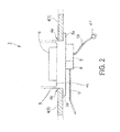
- the tank module 3 has a pot-shaped housing 5, which in Fig. 1 shown schematically and in Fig. 2 is indicated.
- a flange portion 5a may be present after insertion of the tank module 3 in the tank 1 at the bottom of the tank 1 (inside or outside) with appropriate seals.
- Fig. 2 shows inside the tank module 3 at its in Fig. 2 overhead surface a functional area 6, which illustrates in a general form that in the tank module 3 further components and components are arranged, by means of which certain functions are achieved. These components and components serve on the one hand to detect the properties of the liquid and on the other hand to treat it, and will be described in detail below with regard to their structure and their respective function.
- the general functional area 6 merely illustrates that further components are provided in this area of the tank module 3.
- a removal tube 7 is shown, which is arranged at a discharge area 8.
- a control device 9 is provided, which is designed such that the individual components described below can be operated and detections can be carried out.
- the control device 9 has for connection to a power supply device and / or an external computer system (23, Fig. 4 ) on a multi-pole connecting line 10.
- the connecting line 10 may have a corresponding plug device 11 for providing the necessary connections.
- Fig. 3 is shown schematically and in simplified form a part of the tank module 3 according to the first embodiment, wherein the representation is limited to the portion of the tank module 3, which corresponds to the functional area 6.
- the further details of the tank module 3 are omitted for simplicity of illustration.
- a base plate 12 is provided, on which the components of the functional area 6 described below are arranged.
- the tank module 3 comprises according to Fig. 3 various detection devices and other means for performing measures for the treatment of the fluid medium in the form of the liquid 2.
- the components of the tank module 3 described below are lapped by the liquid 2 or are in the liquid second
- a level detection device which is hereinafter referred to as level gauge 13.
- the level gauge 13 comprises means (not shown in the figures) for transmitting ultrasonic signals into the liquid 2 and receiving reflected ultrasonic signals from the liquid 2, so that depending on the total duration of the received ultrasonic signals to a filling level or a level of the liquid 2 in the tank 1 can be closed.
- the main reflection of the ultrasonic signals takes place on the surface of the liquid 2.
- the level gauge 13 is connected to the control device 9 via corresponding connection lines, so that data and instructions (bidirectional) and a required electrical power can be transmitted.
- the tank module 3 further comprises a first temperature detection device, which is referred to below as the first temperature sensor 14.
- the first temperature sensor 14 is in direct communication with the level gauge 13 and detects the temperature of the liquid inside the level meter 13 and in its immediate vicinity, so that when detecting the duration of the ultrasonic signals to determine the level of the liquid 2 in the tank 1, the temperature the liquid 2 in the range of the level gauge 13 can be considered.
- the tank module 3 further comprises a property sensor 15, which is designed to detect the properties of the liquid 2.
- the property sensor 15 may include means for performing detections, for example by means of impedance spectroscopy or to detect turbidity of the liquid 2 (as an indication of impurities in the liquid 2), so that in connection with the detection results of the property sensor 15 can be concluded on a physical and / or chemical nature of the liquid 2, such as a concentration the aqueous urea solution.
- a concentration the aqueous urea solution such as a concentration the aqueous urea solution.
- the current concentration of the liquid 2 (as a solution of certain chemical substances) can be determined.
- the property sensor 15 is also connected to the control device 9 by means of corresponding connection lines for the transmission of data and electrical power.
- the tank module 3 further comprises a filter device 16, which is connected via a connecting element 17 with a pump 18. To remove the liquid 2 from the tank 1, the liquid 2 flows through the filter device 16 and in a correspondingly filtered form through the connecting element 17 to the pump 18, the (filtered) liquid 2 via the sampling tube 7 and the outlet region 8 to a (not shown ) Promotes exhaust system of an internal combustion engine or to another point of consumption.
- the filter device 16 and the pump 18 are in Fig. 3
- the filter device 16 and the pump 18 can also be arranged directly next to each other, so that the connecting element 17 is dispensable.
- the filter device 16, the pump 18, the outlet region 8 and the extraction tube 7 can also be referred to collectively as a removal device which (together with the heating device 19) is preferably arranged in a central region of the base plate 12 of the tank module 3.
- a heating device 19 is provided which on the one hand surrounds the filter device 16 at least partially and on the other hand flows around the liquid 2.
- the heater 19 is in terms of a transmission of data and electrical power with the controller 9 via corresponding lines in combination.
- the heater 19 can be operated so that at least for a very highly cooled liquid 3 below freezing (for example, lower than about -11 ° C at an aqueous urea solution) freezing is prevented or already frozen liquid 2 is thawed again, so that soon after starting the internal combustion engine, a sufficient amount of liquid reducing agent is available for effective exhaust gas purification.
- a very highly cooled liquid 3 below freezing for example, lower than about -11 ° C at an aqueous urea solution
- the above-described components of the tank module 3, which are arranged on the base plate 12 as part of the housing 5 of the tank module 3, are in corresponding connection with the control device 9, so that the control device 9 is provided, on the one hand, to control the respective components. for example, to perform detections or make a treatment of the liquid 2, for example, to operate the pump 18 and that on the other hand recorded and processed detection results, so that a general control of the operation of the tank module 3 is ensured or individual regulations, such as a temperature control in Connection with a power control of the heater 19 or the capacity of the pump 18 are possible.
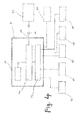
- Fig. 4 shows in this connection a block diagram of the arrangement of the tank module 3 with regard to the electrical connections (connections to the power supply and to the transmission of data and instructions in both directions).
- the control device 9 comprises a central unit 20 for carrying out control and / or regulating measures and for evaluating data, for example in conjunction with corresponding detection results. Programs and corresponding data may be temporarily or permanently stored in a memory 21.
- the control device 9 further comprises an input / output area, which is referred to below as interface 22.
- the interface 22 communicates with the central unit 20 as well as with the aforementioned components of the tank module 3, such as the level gauge 13, the first temperature sensor 14, the property sensor 15, the pump 18 and the heater 19 in connection.
- the central unit 20 can be connected via the connecting line 10 and a possible plug-in device 11 to an external computer system 23 (which is not part of, but can be connected to, the tank module 3).
- the control device 9 causes a triggering of the corresponding components, for example for performing acquisitions, and records the detection data for evaluation.
- the temperature of the liquid in the vicinity of the level meter 13 is detected continuously or at certain time intervals by means of the first temperature sensor 14 and it is also operated the property of the sensor for detecting the properties of the liquid 2.
- the pump 18 is controlled in dependence on this requirement, as is the heating device 19 as a function of the temperature.
- Fig. 4 further shows an external, ie outside the tank module 3 arranged temperature sensor 24, which is provided as needed for detecting the ambient temperature in which the industrial machine, the motor vehicle or the like is operated.
- the external or external temperature sensor 24, which is not directly part of the tank module 3, can also be connected to the control device 9 and supplies temperature data intended for evaluation as ambient conditions, for example during operation of a motor vehicle.
- Fig. 5 shows further details of the heater 19, which will be described in detail below with regard to their structure and operation.
- the heating device 19 comprises a control unit 25 and at least a first heating element 26 and a second heating element 27, which in Fig. 5 in the form of resistors (heating resistors) R1 and R2 are illustrated.
- the heating device 19 and in particular the two heating elements 26 and 27 are (electrically insulated and corrosion-protected on the surface) in communication with the liquid 2, so that a heat transfer can take place on the liquid 2.
- the further heat coupling of the two heating elements 26 and 27 via the liquid 2 is illustrated by means of an arrow 28.
- the heater 19 includes the at least two heating elements (for example, the heating elements 26 and 27), wherein the present invention is not set to this number. Rather, more than two heating elements can be provided.
- the individual heating elements, such as the at least two heating elements 26 and 27, may be of a similar design or may also have different electrical values (for example the individual heating power) and mechanical designs or have arrangements.
- control unit 25 receives corresponding control signals and electrical power from the control device 9.
- control device 9 directly controls the at least two heating elements 26 and 27 (heating resistors R1 and / or R2) or other heating elements of the same or different type.
- both heating elements 26 and 27 can be operated simultaneously, or one of the two heating elements (26 or 27 ) are operated to heat the liquid 2, wherein the corresponding heating power is supplied. If the two heating elements 26 and 27 designed differently in terms of their heating, there are three different heating outputs at the same supply voltage by means of which at least two heating elements 26 and 27, by means of which, depending on a temperature detection, the heating of the liquid 2 or thawing of the liquid 2 at low temperatures is possible.
- the first temperature sensor 14 is in the vicinity of the level gauge 13 and thus preferably arranged on one side of the base plate 12 of the tank module 3 at a certain distance from the heating device 19, the filter device 16 and the pump 18.
- the temperature information of the first temperature sensor 14 can thus provide only approximate values with respect to a temperature of the liquid 2 at the location of the heater 19.
- the control device 9 With the formation of the heating device 19 by means of at least two heating elements (for example, 26 and 27, R1 and R2)) is controlled by the control device 9 in such a way that one of the heating elements (26 or 27) is driven accordingly to deliver heat to heat the liquid 2, and the remaining heating element (27 or 26) is driven in such a way that no heating power is supplied, but a detection of the temperature-dependent resistance of this heating element is detected, for determining the temperature in the vicinity of the heater 19th
- control device 9 causes a corresponding activation of the heating device 19 and in detail of the at least two heating elements 26 and 27, so that depending on the need both heating elements 26 and 27 are driven to heat the liquid 2 or that one of the heating elements 26 or 27 serves as a temperature sensor, which can thus be referred to as a second temperature sensor ,
- a temperature detection can be performed which very accurately and reliably describes the temperature conditions in the immediate vicinity of the heater 19, so that on the one hand can be detected when at very low temperatures, a large heating power is required, and on the other hand can be detected if the temperature of the liquid 2 in the vicinity of the heater 19 is too high to avoid the risk of chemical or physical change of the liquid second
- the control device 9 can control one of the two heating elements 26 or 27 at least temporarily or continuously as a second temperature sensor, with the control of the at least two heating elements 26 and 27 being possible in such a way that one of the heating elements 26 or 27 is early in order to warm up the Liquid 2 is driven while the other heating element is driven as a second temperature sensor, and after a safe detection of the ambient temperature within the liquid 2, both heating elements 26 and 27 are driven at elevated heat demand for heating the liquid 2. Cyclically or continuously for a predetermined period of time, one of the two heating elements 26 or 27 can always be operated independently of the other one as (second) temperature sensor. The at least two heating elements 26 and 27 are thus shelled in the form of two separate circuits. Both heating elements 26 and 27 can be separated by the control device 9, d. H. be driven independently of each other and / or operated the same or different.
- the filter device 16 and the pump 18 are ensured, so that even under unfavorable temperature conditions, a rapid heating of the liquid 2 is ensured, with overheating can be effectively avoided.
- the temperature detection can be detected without or with only a very small thermal delay, since the heater 19 and thus the second temperature sensor operated heating element 26 or 27 adjacent to the removal device (7, 8, 16, 18) is arranged. With the electrical separation of the two heating elements 26 and 27, in principle, the other heating element can be operated for heating or (at least temporarily) switched off, while the one heating element is driven and operated as a second temperature sensor.
- the heating device 19 may consist of at least two resistor coils for forming the two heating resistors R1 and R2 of the first and second heating elements 26 and 27.
- the two resistor coils may be formed on a common support for each separate controls, wherein the direct thermal contact of the coils with each other (the respective heating elements 26 and 27) is reduced, while the contact with the one hand to be heated and on the other hand to be detected with respect to the temperature liquid 2 is guaranteed.
- the resistance coils of the heating elements 26 and 27 are separately controllable and operable.
- the heating device 19 may be configured such that one of the at least two heating elements 26 or 27 is disposed immediately adjacent to the filter device 16, while the other of the at least two heating elements 26 or 27 is disposed immediately adjacent to the pump 18. In this way, a realistic temperature detection of the liquid 2 in the surrounding area of the filter device 16 and the pump 18 is also ensured.
- the at least two heating elements 26 and 27 may be arranged adjacent to the filter device 16, and at least one further heating element may be arranged on or adjacent to the pump 18.
- the further (in the present example, the third) heating element may also surround the pump at least partially. All of these multiple heating elements (26, 27, ...) are separated and operate independently with the same or different functions (heating or temperature sensing).
- a reliable temperature detection with no or only a small thermal delay can be achieved, which provides an information regarding the temperature of the liquid in the vicinity of the heating device and also the removal device (7, 8, 16, 18).
- changes of, for example, the electrical characteristics can be detected, especially by comparing temperature detections by means of one or the other of the at least two heating elements 26 and 27 and a subsequent correlation of the detection values.
- line breaks can be detected.
- the electrical properties of the at least two (or more) heating elements 26 and 27 can be constantly checked with regard to the electrical values and also with regard to a plausibility of the detection (verification of the values).
- the arrangement according to the invention is also resistant to, for example, in a motor vehicle raging shocks and vibrations.
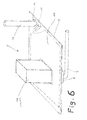
- Fig. 6 shows a second embodiment of the arrangement of the tank module 3 in comparison to the arrangement of the tank module 3 according to the first embodiment in conjunction with Fig. 3 ,
- Fig. 6 are in the same manner as in the first embodiment according to Fig. 3 arranged on the base plate 12 of the level gauge 13 and the first temperature sensor 14 and the property sensor 15.
- the structure and functions of these components are similar to the corresponding components of the first embodiment, so that further description is omitted.
- a filter-pump unit 29 is arranged on the base plate 12 and in simplified form in connection with a block, in which the filter device 16 and the pump 18 are integrated.
- the filter-pump unit 29 is located in a central or central region of the base plate 12 and is in communication with the outlet region 8 and the removal tube 7 for removing the liquid 2, which surrounds the above-mentioned components of the tank module 3 and flows around.
- Connection lines of the individual components to the control device 9 are omitted for simplicity of illustration, but are similar to the corresponding connection lines according to Fig. 3 ,
- a heater 119 which has a similar effect of heating the liquid 2 as the heater 19 according to the first embodiment, but deviates in structure from the arrangement of the heater 19 of the first embodiment.
- the heater 119 according to the second embodiment is arranged flat on the base plate 12, wherein this in Fig. 6 is indicated by a dashed line within which the heater 119 is formed. In the area of the filter-pump unit 29, the heater 119 may be recessed. With this arrangement, the heater 119 is in the same manner as the heater 19 of the first embodiment adjacent to the filter pump unit 29 and thus adjacent to the removal device, which comprises the above-described components 7, 8 and 29 according to the second embodiment.
- the heating device 119 can be arranged as a film with corresponding resistance surfaces on the base plate 12, or the resistance surfaces can be formed directly on the base plate 12, for example by means of a printing operation, wherein the heater 119 is a large area in communication with the liquid 2 and at their (in Fig. 6 ) has an insulating layer on the upper surface which electrically isolates the heater 119 from the liquid 2 and protects it from corrosion. Furthermore, the at least two heating elements (surface resistance regions R11 and R12) or also further heating elements are electrically separated from one another for individual control by the control device 9
- the schematic diagram of the heater 19 according to the first embodiment and the representation in Fig. 5 also applies to the heater 119 according to the second embodiment, wherein the heater 119 also has at least two individual heating elements 126 and 127.
- This in Fig. 4 Block diagram shown also applies to the tank module 3 according to the second embodiment (schematic diagram).
- FIG. 7 Further details of the heater 119 according to the second embodiment, wherein the flat executed at least two heating elements 126 and 127 in the form of flat substantially irregular resistance regions or heating resistors R11 and R12 are shown. Both heating elements 126 and 127 thus have irregular surfaces which are formed as resistance regions and which partially mesh so that surfaces of one of the two heating elements are partially surrounded by surfaces of the respective other heating element.
- the surface of the respective heating elements 126 and 127 facing the liquid 2 is insulated and protected against corrosion, but ensures good thermal coupling for transmitting the heating heat of the heating device 119 to the liquid 2 is.
- Fig. 7 shows the irregular surface configurations of the at least two heaters 126 and 127, which can be controlled separately and independently either directly via the control device 9 or the control unit 125.
- Fig. 7 thus schematically illustrates a part of the base plate 12 of the tank module (for simplicity without further components), wherein only the irregular surfaces of the surface heating resistors R11 and R12 of the respective at least two heating elements 126 and 127 are shown.
- Fig. 7 (and schematically in Fig. 5 ) are shown by way of example the two heating elements 127 and, wherein the invention is not fixed thereto and also more than two separately controllable heating elements can be provided.
- the at least two or even more than two heating elements 126 and 127 can be embodied identically or differently with regard to their electrical values or the surface area and surface shape on the base plate 12.
- FIG Fig. 7 the hatching of the surface of the second heating element 127 is not a sectional view but serves to facilitate differentiation of the at least two heating elements 126 and 127 and the corresponding resistance regions (heating resistors R11 and R12).
- the at least two heating elements 126 and 127 may be separately controlled to provide a corresponding heating power for heating the liquid 2, or one of the at least two heating elements 126 or 127 may be energized to emit heat, and the other heating element 127 or 126 may be referred to as serve the second temperature sensor. After a temperature detection, both heating elements can also be operated temporarily for heat release at the same time (ie for a predetermined period of time).
- a coupling between the at least two heating elements 126 and 127 required for heat transfer is formed via the liquid 2, which is arranged flat over the heating elements 126 and 127 and with this arrangement of the second embodiment with the areal configuration of the heating resistors R11 and R12 an approximately uniform temperature distribution in the region of the liquid 2 adjacent to the heating device 119 is achieved.
- the relevant heating element 126 or 127 which is operated as the second temperature sensor, spatially and to some extent also thermally (functionally) decoupled from the first temperature sensor 14.
- the arrangement according to the second embodiment has the advantage that the amount of heat emitted by the heating device 19 (from at least one of the two heating elements 126 and 127) has a large surface area on the liquid 2 can be transferred so that relatively quickly, the liquid can be heated or in the case of freezing the liquid 2 thawing fast in the lower part of the tank module 3 is ensured directly above the heater 119 and thus the thawed liquid 2 by means of the pump 18 or the filter Pump unit 29 (or the removal device) can be transported to a place of consumption.
- the embodiment as areal resistance areas, a heat dissipation over a large area or a temperature detection can be achieved, which takes place essentially averaged over this area and is therefore meaningful
- one of the two heating devices 126 or 127 according to the second embodiment is operated temporarily or continuously as the second temperature sensor, a temperature detection is carried out in a very precise manner over a large area, which in conjunction with the planar arrangement of the respective heating elements 126 and 127 a realistic average value over the temperature conditions in the liquid or the frozen liquid 2 supplies.
- a temperature detection is carried out in a very precise manner over a large area, which in conjunction with the planar arrangement of the respective heating elements 126 and 127 a realistic average value over the temperature conditions in the liquid or the frozen liquid 2 supplies.
- both heaters 126 and 127 can be controlled to output a heating power, while temporarily for detecting the temperature values one of the two heating elements 126 or 127 is driven in the function of the second temperature sensor.
- control device 9 can directly control the two heaters 126 and 127 according to the desired function (sensor or heater).
- the heating element of the heater 126 or 127 disposed adjacent to the filter-pump unit 29 or the extraction device may be driven in the direction of heating to achieve a desired temperature of the liquid 2 in the vicinity of these components, while the other the at least two heating elements 126 or 107 are operated as the second temperature sensor. It is guaranteed an approximately delay-free temperature detection.
- the illustration of the heater 119 according to the second embodiment in Fig. 7 is simplified and schematic, wherein in a similar area distribution, the at least two heating elements 126 and 127 on the according Fig. 6 available surface of the base plate 12 may be formed.
- the filter device 16 and the pump 18 immediately adjacent to each other, but to arrange separately.
- a corresponding recess is preferably provided in the at least two heating elements 126 and 127.
- the base plate 12 is shown for ease of illustration as a flat plate forming part of the tank module 3 and the housing 5, respectively.
- the present invention is not limited in such a way that the base plate 12 is a flat plate, but it is possible to form the base plate 12 as an upwardly or downwardly curved or spherically curved plate, in which case the flat formed resistance regions R11 and R12 of the at least two heating elements 126 and 127 follow substantially the contour and shape of the base plate 12.
- the function of giving off heat for heating the liquid 2 and performing temperature detection with one of the at least two heating elements 126 and 127 (or 26 and 27 according to the first embodiment) is independent thereof.
- the at least two heating devices 26 and 27 or 126 and 127 thus form two separately controllable or even galvanically isolated circuits, so that the at least two or more and mutually insulated heating elements are controlled independently of each other with respect to the heating power.
- the respective individual heating elements 26, 27, 126 and 127 of the heaters 19 and 119 can be switched in any combination as a heater or as a second temperature sensor, so that with respect to the detection of the temperature and alternately different heating devices can be temporarily controlled as a second temperature sensor to in this way, over a large area and in conjunction with different conditions of temperature conditions in the liquid 2 to detect the exact temperature or reliable average temperature over a relatively large area (second embodiment).
- both the same or different heating elements can be switched or controlled at certain times (temporarily) for heating or as a temperature sensor, it is possible to clearly detect defects of the individual heating elements or deteriorations occurring during operation, so that on the one hand a permanent Functional test is ensured, and on the other hand with at least two heating elements of the heater has a certain redundancy.
- FIG. 4 In this embodiment is in the heater 19 according to Fig. 3 or the heater 119 according to Fig. 6 only one heating element before, the means of the control device 9 as shown in FIG Fig. 4 can be controlled.
- the basic structure is the same as that used in connection with the first and second embodiments on the basis of FIGS. 1 and 2 has been described.
- the control by the control device 9 comprises the activation of the heating device 19 or 119 for the release of heat by applying corresponding voltage and currents to the heating element as a function of a heating power to be provided become.
- the heating device 19 or 119 which is in thermal contact with the liquid 2 and which has the one heating element serves in this case for heating or thawing the liquid 2.
- the control device 9 is likewise designed to control the heating element of the heating device in such a way that, instead of emitting heat, it serves to detect the temperature of the liquid 2 located substantially in the vicinity of the heating element. By detecting the electrical values of the heating element, knowledge of the temperature of the liquid is obtained in connection with a characteristic characteristic of the heating element with respect to an electrical resistance and an ambient temperature (here the temperature of the liquid).
- the heating element of the heater 19 or 119 may in the form of a resistance coil (resistance wire) according to Fig. 3 or in the form of a flat resistance area according to Fig. 6 available.
- the resistance coil the (at least) one heating element may be arranged, as described in connection with the first embodiment. In the case of training with a sheet-like resistance region, this can occupy at least a part of the base plate 12 or the entire area of the base plate 12, as it is in Fig.
- the areal resistance area can be meandering, in the form of individual series and / or parallel resistance strips or spirally formed.
- a heat dissipation over a large area or a temperature detection can be achieved, which takes place essentially averaged over this area and is thus meaningful.
- the control device 9 can control the heating device 19 or 119 in a corresponding manner, that either the heating element is operated for heating or for temperature detection.
- the control device 9 causes a temporal control of the heater 19 or 119 such that temporarily the heating element for heating is controlled, or that the heating element is temporarily driven to the temperature detection, wherein the respective time ranges do not overlap.
- the control of one or the other operation is made as a function of demand or according to a programming of the control device 9.
- the temperature sensing may occur simultaneously with the operation of the heating since the resistance temperature characteristic of the PTC resistor is indicative of the temperature in front of a resistor (current and voltage ).
- the simultaneous heating and temperature detection is to be understood in the sense of a control for heating and simultaneous detection of the electrical values of the heating element as a measure of the temperature thereof.
Landscapes
- Exhaust Gas After Treatment (AREA)
- Heat-Pump Type And Storage Water Heaters (AREA)
Abstract
Die Erfindung betrifft ein Tankmodul zum Einsetzen in einen Öffnungsbereich eines Tanks, der eine Flüssigkeit enthält, die mittels einer Entnahmeeinrichtung (7, 8, 16, 18) entnommen werden kann. Das Tankmodul umfasst eine benachbart zu der Entnahmeeinrichtung (7, 8, 16, 18) angeordnete Heizeinrichtung (19), die zumindest zwei Heizelemente aufweist, die unabhängig voneinander angesteuert werden können und in einem thermischen Kontakt zur Flüssigkeit stehen, und eine Steuerungseinrichtung (9), die mit der Heizeinrichtung (19) verbunden ist zur individuellen Ansteuerung der zumindest zwei Heizelemente der Heizeinrichtung (19), so dass eines der Heizelemente zur Abgabe von Wärme und das andere zumindest zeitweilig zur Erfassung der Temperatur der Flüssigkeit angesteuert wird.The invention relates to a tank module for insertion into an opening region of a tank containing a liquid which can be removed by means of a removal device (7, 8, 16, 18). The tank module comprises a heating device (19), which is arranged adjacent to the removal device (7, 8, 16, 18) and has at least two heating elements which can be controlled independently of one another and are in thermal contact with the liquid, and a control device (9). which is connected to the heating device (19) for individually controlling the at least two heating elements of the heating device (19), so that one of the heating elements is driven to emit heat and the other at least temporarily to detect the temperature of the liquid.
Description
Die vorliegende Erfindung betrifft ein Tankmodul für einen Flüssigkeitstank, und insbesondere ein Tankmodul mit Einrichtungen zur Erfassung der Eigenschaften der Flüssigkeit und zur Behandlung derselben.The present invention relates to a tank module for a liquid tank, and more particularly to a tank module having means for detecting the properties of the liquid and treating it.
In bekannter Weise befinden sich in einem Tank Brennstoffe oder weitere Hilfsstoffe zur Unterstützung oder Verbesserung der Verbrennung, wobei diese Hilfsstoffe im Allgemeinen in einem separaten Tank oder Behälter in einem Kraftfahrzeug mitgeführt werden, oder der separate Tank in Verbindung mit einer industriellen Maschine angeordnet ist, in der die Hilfsstoffe verwendet werden. Derartige Hilfsstoffe liegen beispielsweise in der Form von fluiden Reduktionsmitteln zur Verminderung schädlicher Komponenten im Abgas von Brennkraftmaschinen vor.In a known manner, fuels or other auxiliary substances for aiding or improving combustion are contained in a tank, these auxiliary substances generally being carried in a separate tank or container in a motor vehicle, or the separate tank being arranged in connection with an industrial machine the adjuvants are used. Such auxiliaries are present, for example, in the form of fluid reducing agents for reducing harmful components in the exhaust gas of internal combustion engines.
Durch die Verbrennung eines Brennstoffs in Brennkraftmaschinen werden in den Abgasen der Verbrennung umweltschädliche Stoffe gebildet, so dass eine zumindest teilweise Reinigung der Abgase erforderlich ist. Insbesondere ist es erforderlich, die Abgase von Diesel-Brennkraftmaschinen zumindest teilweise zu reinigen, wobei in Verbindung mit verschärften gesetzlichen Bestimmungen der Anteil an Stickoxiden (NOx) erheblich vermindert werden kann.By burning a fuel in internal combustion engines harmful substances are formed in the exhaust gases of the combustion, so that an at least partial cleaning of the exhaust gases is required. In particular, it is necessary to at least partially clean the exhaust gases of diesel internal combustion engines, wherein in conjunction with tightened legal provisions, the proportion of nitrogen oxides (NOx) can be significantly reduced.
Hierzu wird in einer Abgasanlage einer Diesel-Brennkraftmaschine in Verbindung mit einem gasförmigen Ammoniak als Reduktionsmittel, das in den Abgasstrom eingebracht wird, der Anteil der Stickoxide des Abgases vermindert, wobei das gasförmige Ammoniak mit den Stickoxiden des Abgases selektiv zu Stickstoff und Wasser reagiert.For this purpose, the proportion of nitrogen oxides in the exhaust gas is reduced in an exhaust system of a diesel internal combustion engine in conjunction with a gaseous ammonia as reducing agent, wherein the gaseous ammonia reacts with the nitrogen oxides of the exhaust gas selectively to nitrogen and water.
Das gasförmige Ammoniak wird bereitgestellt durch Zuführen einer wässrigen Harnstofflösung in die Abgasanlage bzw. den Abgasstrom der Diesel- Brennkraftmaschine. Die wässrige Harnstofflösung wird zusätzlich zu dem Brennstoff für die Brennkraftmaschine in geringerer Menge und in einem separaten Tank mitgeführt.The gaseous ammonia is provided by supplying an aqueous urea solution into the exhaust system of the diesel engine. The aqueous urea solution is carried in addition to the fuel for the internal combustion engine in a smaller amount and in a separate tank.
Hinsichtlich des Betriebs der Fahrzeuge mit derartigen Reduktionsmitteln und speziell in Verbindung mit der wässrigen Harnstofflösung ist bei winterlichen Temperaturen erheblich unter 0°C zu beachten, dass die wässrige Harnstofflösung bei etwa -11 °C ausflockt bzw. gefriert. Der besondere Tank für die wässrige Harnstofflösung bedarf somit einer Heizung, um bei tiefen Temperaturen zumindest einen Teil der im Tank befindlichen Harnstofflösung kurzfristig flüssig zu halten oder zu verflüssigen, so dass auch unter diesen Bedingungen ein Einbringen in den Abgasstrom möglich ist.With regard to the operation of vehicles with such reducing agents and specifically in In case of winter temperatures considerably below 0 ° C, it should be noted that the aqueous urea solution flocculates or freezes at about -11 ° C. The special tank for the aqueous urea solution thus requires heating in order to keep at least some of the urea solution in the tank at low temperatures liquid or liquefied for a short time so that it is possible to introduce it into the exhaust gas flow even under these conditions.
In diesem Zusammenhang offenbart die Druckschrift
Die Druckschrift
Die Druckschrift
Gemäß der
Die vorstehend beschriebenen bekannten Heizeinrichtungen dienen im Wesentlichen dazu, das in dem Tank befindliche Fluid oder die Flüssigkeit (beispielsweise eine wässrige Harnstofflösung) vor einem Einfrieren zu bewahren oder nach dem Einfrieren bei tiefen Umgebungstemperaturen ein Auftauen zu bewirken. Die bekannten Heizeinrichtungen sind jedoch im Wesentlichen in der Lage, lediglich einen begrenzten Raum innerhalb des Tankmoduls und auch innerhalb des Tanks in entsprechender Weise zu erwärmen, um den Schutz vor einem Einfrieren oder das Auftauen wirksam zu erreichen. Insbesondere ist es schwierig, eine Temperaturregelung des Aufheizens der Flüssigkeit in dem Behälter durchzuführen, da mit den vorgesehenen Temperatursensoren nicht immer eine verlässliche Information über die aktuelle Temperatur der Flüssigkeit in dem Tank erhalten werden kann, insbesondere, wenn die Heizeinrichtung kompakt ausgeführt ist und sich der Temperatursensor in einem bestimmten Abstand zur Heizeinrichtung befindet. Eine mangelnde Erwärmung der Flüssigkeit und damit ein verzögertes Auftauen oder eine lokale erhöhte Erwärmung können die Folge sein. Dies führt jedoch in Abhängigkeit von der Art der Flüssigkeit in dem Tank zumindest teilweise zu unerwünschten Änderungen der Eigenschaften der Flüssigkeit.The known heating means described above essentially serve to prevent the fluid in the tank or the liquid (for example an aqueous urea solution) from freezing or to cause thawing after freezing at low ambient temperatures. However, the known heaters are substantially capable of heating only a limited space within the tank module and also within the tank in a corresponding manner in order to effectively achieve protection against freezing or thawing. In particular, it is difficult to carry out a temperature control of the heating of the liquid in the container, since the temperature sensors provided can not always provide reliable information about the actual temperature of the liquid in the tank, in particular if the heating device is made compact and the Temperature sensor is located at a certain distance from the heater. A lack of heating of the liquid and thus a delayed thawing or a local increased heating can be the result. However, depending on the type of liquid in the tank, this at least partially leads to undesirable changes in the properties of the liquid.
Der vorliegenden Erfindung liegt daher die Aufgabe zugrunde, ein Tankmodul für einen Flüssigkeitstank der eingangs genannten Art derart auszugestalten, dass auf einfache Weise eine effektive Erwärmung und eine genaue Erfassung der Temperatur der Flüssigkeit gewährleistet sind.The present invention is therefore based on the object, a tank module for a liquid tank of the type mentioned in such a way that in a simple manner effective heating and accurate detection of the temperature of the liquid are guaranteed.
Erfindungsgemäß wird diese Aufgabe mit den in den Schutzansprüchen angegebenen Merkmalen gelöst.According to the invention this object is achieved with the features specified in the protection claims.
Die Erfindung betrifft ein Tankmodul zum Einsetzen in einen Öffnungsbereich eines Tanks, der eine Flüssigkeit enthält, die mittels einer Entnahmeeinrichtung entnommen werden kann. Das Tankmodul umfasst eine benachbart zu der Entnahmeeinrichtung angeordneten Heizeinrichtung, die zumindest zwei Heizelemente aufweist, die unabhängig voneinander angesteuert werden können und in einem thermischen Kontakt zur Flüssigkeit stehen, und eine Steuerungseinrichtung, die mit der Heizeinrichtung verbunden ist zur individuellen Ansteuerung der zumindest zwei Heizelemente der Heizeinrichtung, so dass eines der Heizelemente zur Abgabe von Wärme und das andere zumindest zeitweilig zur Erfassung der Temperatur der Flüssigkeit angesteuert wird.The invention relates to a tank module for insertion into an opening region of a tank containing a liquid which can be removed by means of a removal device. The tank module comprises a heater arranged adjacent to the removal device, which has at least two heating elements which can be controlled independently of each other and are in thermal contact with the liquid, and a control device which is connected to the heating device for individually controlling the at least two heating elements Heating device, so that one of the heating elements for the release of heat and the other is at least temporarily driven to detect the temperature of the liquid.
Mit der erfindungsgemäßen Anordnung kann somit erreicht werden, dass einerseits in effektiver Weise die im Tank befindliche Flüssigkeit in vorbestimmter Weise aufgewärmt wird, und dass gleichzeitig eine genaue und aussagekräftige Erfassung der Temperatur gewährleistet ist, so dass beispielsweise in Verbindung mit der Temperaturerfassung eine Regelung der der Heizeinrichtung zugeführten Heizleistung möglich ist. Die Heizeinrichtung des erfindungsgemäßen Tankmoduls ist in der Weise ausgebildet, dass zumindest zwei Heizelemente vorgesehen sind und dass die Heizelemente getrennt angesteuert werden können, so dass ein Teil der Heizeinrichtung zum Bewirken einer Aufheizung angesteuert wird, während ein weiterer Teil der Heizeinrichtung unabhängig vom ersten Teil der Heizeinrichtung zumindest zeitweilig zur genauen Erfassung der Temperatur der Flüssigkeit dienen kann.With the arrangement according to the invention can thus be achieved, on the one hand in an effective manner, the liquid in the tank is heated in a predetermined manner, and that at the same time an accurate and meaningful detection of the temperature is ensured, so that, for example, in conjunction with the temperature detection, a regulation of the Heating device supplied heating power is possible. The heating device of the tank module according to the invention is formed in such a way that at least two heating elements are provided and that the heating elements can be controlled separately, so that a part of the heater is driven to effect a heating, while another part of the heater regardless of the first part of the Heating device can at least temporarily serve to accurately detect the temperature of the liquid.
Auf diese Weise wird ein verlässliches Erfassungsergebnis der aktuellen Temperatur der Flüssigkeit erhalten, so dass darauf aufbauend die Heizleistung gesteuert oder auch geregelt werden kann. Die Aufheizung der Flüssigkeit und die Temperaturerfassung können gleichzeitig erfolgen. Mit der erfindungsgemäßen Anordnung der zumindest zwei Heizelemente der Heizeinrichtung sind das der Heizung dienende und das der Temperaturerfassung dienende Heizelement benachbart zueinander angeordnet, so dass auch in thermischer Hinsicht keine oder nur eine sehr geringe (im Allgemeinen vernachlässigbare) Verzögerung der Erfassung einer aktuellen Temperatur auftreten kann. Eine Steuerungseinrichtung kann hierfür die entsprechende Ansteuerung der zumindest zwei Heizelemente vornehmen, so dass zumindest ein Heizelement mit Heizleistung versorgt wird (elektrische Werte von Strom und Spannung) und das andere Heizelement in Verbindung mit der Erfassung seiner elektrischen Werte (Strom, Spannung, Widerstand) eine aktuelle und verlässliche (uns speziell eine rasche) Temperaturinformation liefert. Es besteht ferner die Möglichkeit, bei dem Vorhandensein eines weiteren Temperatursensors die jeweiligen Erfassungswerte zu vergleichen und Korrekturen vorzunehmen bzw. die Erfassungswerte auf eine Plausibilität zu prüfen.In this way, a reliable detection result of the current temperature of the liquid is obtained, so that based on the heating power can be controlled or regulated. The heating of the liquid and the temperature detection can take place simultaneously. With the arrangement according to the invention of the at least two heating elements of the heating device, the heating element and the temperature detection serving heating element are adjacent to each other, so that even in thermal terms no or only a very small (generally negligible) delay the detection of a current temperature can occur , A control device can perform the corresponding control of the at least two heating elements, so that at least one heating element is supplied with heating power (electrical values of current and voltage) and the other heating element in conjunction with the detection of its electrical values (current, voltage, resistance) current and reliable (especially a quick) temperature information provides. It is also possible, in the presence of a further temperature sensor, to compare the respective detection values and to make corrections or to check the detection values for plausibility.
Ein sicherer Betrieb einer Maschine in Verbindung mit dem erfindungsgemäßen Tankmodul, und beispielsweise ein sicherer Betrieb einer Diesel-Brennkraftmaschine in Verbindung mit der Verwendung einer wässrigen Harnstofflösung zur Abgasreinigung ist somit gewährleistet. Ungeachtet möglicher niedriger Außentemperaturen kann in geregelter Weise eine entsprechend temperierte Flüssigkeit, wie beispielsweise das genannte Reduktionsmittel, zur Verfügung gestellt werden, und im Falle sehr tiefer Außentemperaturen unter -11 °C und bei Abstellen beispielsweise des Kraftfahrzeugs im Freien kann schnell eine Aufheizung der Flüssigkeit und bedarfsweise ein Auftauen mit entsprechender genauer Temperaturüberwachung durchgeführt werden.Safe operation of a machine in conjunction with the tank module according to the invention, and for example safe operation of a diesel internal combustion engine in conjunction with the use of an aqueous urea solution for exhaust gas purification is thus ensured. Regardless of possible low outside temperatures can be regulated Way a suitably tempered liquid, such as said reducing agent, are provided, and in the case of very low outside temperatures below -11 ° C and when parking, for example, the motor vehicle outdoors can quickly heating the liquid and, if necessary, thawing with appropriate accurate temperature monitoring be performed.
Das Tankmodul ist des Weiteren auf einfache Weise zu fertigen, da das Tankmodul keine bestimmte Form aufweisen muss und die Heizeinrichtung gemäß der vorliegenden Erfindung und den nachstehend noch beschriebenen Ausführungsbeispielen in guter Wärmekopplung mit der Flüssigkeit (beispielsweise dem Reduktionsmittel oder einer sonstigen Flüssigkeit) steht, so dass zwischen dem der Aufheizung dienenden Heizelement und dem der Temperaturerfassung dienenden Heizelement über die Flüssigkeit in dem Tank (und somit auch in dem Tankmodul) eine gute Wärmeübertragung gewährleistet ist.The tank module is furthermore easy to manufacture, since the tank module does not have to have a specific shape and the heating device according to the present invention and the embodiments described below is in good thermal coupling with the liquid (for example the reducing agent or another liquid) in that a good heat transfer is ensured between the heating element serving for heating and the heating element serving for detecting the temperature via the liquid in the tank (and thus also in the tank module).
Die Heizeinrichtung kann hierbei in einem vorbestimmten Bereich in dem Tankmodul angeordnet werden, und befindet sich insbesondere in einem unteren Bereich und in der Umgebung einer Auslassöffnung im Tankmodul, so dass in der unmittelbaren Umgebung der Auslassöffnung nach dem Starten der Diesel-Brennkraftmaschine (bei entsprechend tiefen Umgebungstemperaturen) schnell eine Verflüssigung des Reduktionsmittels erreicht werden kann. Im Verlauf des Betriebs kann dann die weitere Umgebung um die Auslassöffnung und schließlich die Gesamtmenge des fluiden Reduktionsmittels in entsprechender Weise aufgewärmt und aufgetaut werden.The heating device can in this case be arranged in a predetermined region in the tank module, and is located in particular in a lower region and in the vicinity of an outlet opening in the tank module, so that in the immediate vicinity of the outlet opening after starting the diesel internal combustion engine (at correspondingly low Ambient temperatures), a liquefaction of the reducing agent can be achieved quickly. In the course of operation, the further environment around the outlet opening and finally the total amount of the fluid reducing agent can then be warmed and thawed in a corresponding manner.
Gemäß einem weiteren Aspekt der vorliegenden Erfindung ist ein Tankmodul vorgesehen zum Einsetzen in einen Öffnungsbereich eines Tanks, der eine Flüssigkeit enthält, die mittels einer Entnahmeeinrichtung entnommen werden kann. Das Tankmodul umfasst eine benachbart zu der Entnahmeeinrichtung angeordneten Heizeinrichtung, die ein Heizelement aufweist, das in einem thermischen Kontakt zur Flüssigkeit steht und das zur Aufheizung der Flüssigkeit und/oder zur Erfassung der Temperatur der Flüssigkeit angesteuert werden kann, und eine Steuerungseinrichtung, die mit der Heizeinrichtung verbunden ist zur Ansteuerung des Heizelements der Heizeinrichtung, so dass das Heizelement zeitweilig zur Abgabe von Wärme und /oder zeitweilig zur Erfassung der Temperatur der Flüssigkeit angesteuert wird.According to a further aspect of the present invention, a tank module is provided for insertion into an opening region of a tank containing a liquid which can be removed by means of a removal device. The tank module comprises a heating device arranged adjacent to the extraction device, which has a heating element which is in thermal contact with the liquid and which can be activated to heat the liquid and / or to detect the temperature of the liquid, and a control device which is connected to the Heating device is connected to drive the heating element of the heating device, so that the heating element is temporarily controlled to output heat and / or temporarily to detect the temperature of the liquid.
Hierdurch wird eine Vereinfachung des Tankmoduls erreicht, wobei die Heizeinrichtung zur Aufheizung oder Temperaturerfassung jeweils zeitweilig und nicht zeitlich überlappend oder auch gleichzeitig angesteuert werden.As a result, a simplification of the tank module is achieved, wherein the heater for heating or temperature detection in each case temporarily and not overlapping in time or be controlled simultaneously.
Weitere Ausgestaltungen der Erfindung sind in den abhängigen Schutzansprüchen angegeben.Further embodiments of the invention are specified in the dependent claims.
In dem Tankmodul können die zumindest zwei Heizelemente der Heizeinrichtung für eine gleiche oder unterschiedliche Heizleistung ausgebildet sein.In the tank module, the at least two heating elements of the heating device can be designed for the same or different heating power.
Die zumindest zwei Heizelemente der Heizeinrichtung können benachbart und isoliert zueinander angeordnet sein, und es kann die Steuerungseinrichtung ausgebildet sein, zeitweilig die beiden Heizelemente zur Abgabe einer Heizleistung anzusteuern.The at least two heating elements of the heating device can be arranged adjacently and insulated from one another, and the control device can be designed to temporarily control the two heating elements for emitting a heating power.
In dem Tankmodul können die zumindest zwei Heizelemente der Heizeinrichtung als drahtförmiger Heizwiderstände ausgebildet sein, oder es können die zumindest zwei Heizelemente der Heizeinrichtung als flächige Widerstandsbereiche ausgebildet sein.In the tank module, the at least two heating elements of the heating device can be designed as wire-shaped heating resistors, or the at least two heating elements of the heating device can be designed as planar resistance regions.
Die flächigen Widerstandsbereiche können gleich große oder unterschiedliche Flächen aufweisen, und es können die flächigen Widerstandsbereiche unregelmäßig geformte Flächen aufweisen, wobei Flächen eines der Widerstandsbereiche Flächen des anderen Widerstandsbereichs teilweise umgeben.The areal resistance areas can have the same or different areas, and the areal resistance areas can have irregularly shaped areas, wherein areas of one of the resistance areas partially surround areas of the other resistance area.
Die flächigen Widerstandsbereiche der zumindest zwei Heizelemente der Heizeinrichtung können als folienförmige oder gedruckte Widerstandsbereiche ausgebildet und auf einer ebenen oder gekrümmten Grundplatte des Tankmoduls angeordnet sein. Die zumindest zwei Heizelemente der Heizeinrichtung können als drahtförmige Heizwiderstände ausgebildet sein, und es kann die Entnahmeeinrichtung eine Filtereinrichtung aufweisen, wobei die Heizwiderstände zumindest teilweise die Filtereinrichtung umgeben können.The planar resistance regions of the at least two heating elements of the heating device can be designed as foil-shaped or printed resistance regions and arranged on a flat or curved base plate of the tank module. The at least two heating elements of the heating device can be designed as wire-shaped heating resistors, and the extraction device can have a filter device, wherein the heating resistors can at least partially surround the filter device.
In dem Tankmodul können die zumindest zwei Heizelemente der Heizeinrichtung als drahtförmige Heizwiderstände ausgebildet sein, und die Entnahmeeinrichtung kann eine Filtereinrichtung und ein Pumpe aufweisen, wobei die Heizwiderstände zumindest teilweise die Filtereinrichtung umgeben können, und wobei ein weiteres Heizelement vorgesehen sein kann, das benachbart zu der Pumpe oder diese zumindest teilweise umgebend angeordnet sein kann.In the tank module, the at least two heating elements of the heating device may be formed as wire-shaped heating resistors, and the extraction device may comprise a filter device and a pump, wherein the heating resistors may at least partially surround the filter device, and wherein a further heating element may be provided adjacent to Pump or this can be arranged at least partially surrounding.
In dem Tankmodul kann das Heizelement der Heizeinrichtung als ein drahtförmiger Heizwiderstand ausgebildet sein, oder es kann das Heizelement der Heizeinrichtung als flächiger Widerstandsbereich ausgebildet sein.In the tank module, the heating element of the heater as a wire-shaped heating resistor be formed, or it may be formed as a flat resistance region, the heating element of the heater.
Der flächige Widerstandsbereich des Heizelements der Heizeinrichtung kann als folienförmiger oder gedruckter Widerstandsbereich ausgebildet und auf einer ebenen oder gekrümmten Grundplatte des Tankmoduls angeordnet sein.The planar resistance region of the heating element of the heating device can be formed as a foil-shaped or printed resistance region and arranged on a flat or curved base plate of the tank module.
Das Heizelement der Heizeinrichtung als drahtförmiger Heizwiderstand ausgebildet sein, und es kann die Entnahmeeinrichtung eine Filtereinrichtung aufweisen und der Heizwiderstand kann zumindest teilweise die Filtereinrichtung umgeben.The heating element of the heating device can be designed as a wire-shaped heating resistor, and the extraction device can have a filter device and the heating resistor can at least partially surround the filter device.
Die Erfindung wird nachstehend anhand von Ausführungsbeispielen unter Bezugnahme auf die Zeichnung näher erläutert. Die Figuren zeigen:
-
Fig. 1 eine Gesamtdarstellung eines Tanks zur Bevorratung einer Flüssigkeit in Form einer Teil-Schnittansicht, wobei das Tankmodul in den Tank eingesetzt ist, -
Fig. 2 eine detaillierte Darstellung der Anordnung des Tankmoduls im Tank, wobei die Darstellung des Tankmoduls auf die wesentlichen Komponenten reduziert ist, -
Fig. 3 eine vereinfachte schematische Darstellung von Teilen des Tankmoduls in einer perspektivischen Ansicht zur Veranschaulichung der einzelnen Komponenten und ihrer Anordnung gemäß einem ersten Ausführungsbeispiel der Erfindung, -
Fig. 4 ein Blockschaltbild zur Veranschaulichung der elektrischen Verbindungen zu den einzelnen Komponenten des Tankmoduls gemäßFig. 3 , -
Fig. 5 eine detaillierte Darstellung des Aufbaus der Heizeinrichtung gemäß dem ersten Ausführungsbeispiel, -
Fig. 6 eine schematische vereinfachte Darstellung eines Teils des Tankmoduls gemäß einem zweiten Ausführungsbeispiels der vorliegenden Erfindung, und -
Fig. 7 eine detaillierte Darstellung des Aufbaus der Heizeinrichtung des Tankmoduls gemäß dem zweiten Ausführungsbeispiel.
-
Fig. 1 an overall view of a tank for storing a liquid in the form of a partial sectional view, wherein the tank module is inserted into the tank, -
Fig. 2 a detailed representation of the arrangement of the tank module in the tank, wherein the representation of the tank module is reduced to the essential components, -
Fig. 3 a simplified schematic representation of parts of the tank module in a perspective view for illustrating the individual components and their arrangement according to a first embodiment of the invention, -
Fig. 4 a block diagram illustrating the electrical connections to the individual components of the tank module according toFig. 3 . -
Fig. 5 a detailed view of the structure of the heater according to the first embodiment, -
Fig. 6 a schematic simplified representation of a portion of the tank module according to a second embodiment of the present invention, and -
Fig. 7 a detailed view of the structure of the heater of the tank module according to the second embodiment.
Nachstehend werden in Verbindung mit den
Die nachfolgende Beschreibung bezieht sich beispielhaft auf die Anordnung des in
In dem Tank 1 weist im Allgemeinen die Flüssigkeit 2 einen bestimmten Füllstand auf, der höher ist als ein in dem Tank eingesetztes Tankmodul 3 mit der erfindungsgemäßen Anordnung. Das Tankmodul 3 wird vollständig von der Flüssigkeit 2 umströmt und befindet sich ferner in einem unteren Teil des Tanks 1, so dass sichergestellt ist, dass auch bei einer niedrigen Füllhöhe (geringer Füllstand) die Flüssigkeit 2 in ausreichendem Maß das Tankmodul 3 umströmt.In the
Das Tankmodul 3 ist in der in
Das Tankmodul 3 ist in
Ein Flanschbereich 5a kann nach dem Einsetzen des Tankmoduls 3 in den Tank 1 am Boden des Tanks 1 (innen oder außen) mit entsprechenden Dichtungen anliegen.A
An der unteren Oberfläche des Tankmoduls 3 ist ein Entnahmerohr 7 gezeigt, das an einem Auslaufbereich 8 angeordnet ist. Zum Betreiben der im Funktionsbereich 6 angeordneten Mehrzahl von Komponenten ist eine Steuerungseinrichtung 9 vorgesehen, die derart ausgebildet ist, dass die einzelnen nachstehend noch beschriebenen Komponenten betrieben und Erfassungen durchgeführt werden können. Die Steuerungseinrichtung 9 weist zum Anschluss an eine Leistungsversorgungseinrichtung und/oder eine externe Computeranlage (23,
Auf der Basis der grundlegenden Anordnung des Tankmoduls 3, wie sie vorstehend in Verbindung mit den
In
Im Einzelnen umfasst das Tankmodul 3 gemäß
Gemäß
Das Tankmodul 3 umfasst ferner eine erste Temperaturerfassungseinrichtung, die nachstehend als erster Temperatursensor 14 bezeichnet wird. Der erste Temperatursensor 14 steht in unmittelbarer Verbindung mit dem Füllstandmesser 13 und erfasst die Temperatur der Flüssigkeit im Inneren des Füllstandmessers 13 und in dessen unmittelbarer Umgebung, so dass bei der Erfassung der Laufzeit der Ultraschallsignale zur Bestimmung des Füllstands der Flüssigkeit 2 im Tank 1 die Temperatur der Flüssigkeit 2 im Bereich des Füllstandmessers 13 berücksichtigt werden kann.The
Das Tankmodul 3 umfasst ferner einen Eigenschaftensensor 15, der ausgebildet ist zur Erfassung der Eigenschaften der Flüssigkeit 2. Der Eigenschaftensensor 15 kann dabei Einrichtungen zur Durchführung von Erfassungen beispielsweise mittels Impedanzspektroskopie oder auch zur Erfassung einer Trübung der Flüssigkeit 2 (als Hinweis auf Fremdstoffe in der Flüssigkeit 2) aufweisen, so dass in Verbindung mit den Erfassungsergebnissen des Eigenschaftensensors 15 auf eine physikalische und/oder chemische Beschaffenheit der Flüssigkeit 2 geschlossen werden kann, wie beispielsweise eine Konzentration der wässrigen Harnstofflösung. In Verbindung mit dem Reduktionsmittel in Form der wässrigen Harnstofflösung ist es erforderlich, dass diese Lösung eine bestimmte Konzentration von Harnstoff im Wasser aufweist, da bei abweichenden Konzentrationen die Effektivität der Abgasreinigung verschlechtert ist. Somit kann mittels des Tankmoduls 3 und des daraufangeordneten Eigenschaftensensors 15 beispielsweise die aktuelle Konzentration der Flüssigkeit 2 (als Lösung bestimmter chemischer Substanzen) ermittelt werden. Der Eigenschaftensensor 15 steht ebenfalls mit entsprechenden Verbindungsleitungen mit der Steuerungseinrichtung 9 in Verbindung zur Übertragung von Daten und elektrischer Leistung.The
Das Tankmodul 3 umfasst ferner eine Filtereinrichtung 16, die über ein Verbindungselement 17 mit einer Pumpe 18 verbunden ist. Zur Entnahme der Flüssigkeit 2 aus dem Tank 1 strömt die Flüssigkeit 2 durch die Filtereinrichtung 16 und in entsprechend gefilterter Form durch das Verbindungselement 17 zur Pumpe 18, die die (gefilterte) Flüssigkeit 2 über das Entnahmerohr 7 und den Auslaufbereich 8 zu einer (nicht gezeigten) Abgasanlage einer Brennkraftmaschine oder zu einer sonstigen Verbrauchsstelle fördert.The
Die Filtereinrichtung 16 und die Pumpe 18 sind in
Gemäß der Darstellung in
Wird die Heizeinrichtung 19 betrieben, wird der Bereich der Flüssigkeit 2 in der unmittelbaren Umgebung der Heizeinrichtung 19 und auch die in der Filtereinrichtung 16 befindliche Flüssigkeit 2 durch Aufnahme der von der Heizeinrichtung 19 abgegebenen thermischen Energie erwärmt. Besteht somit die Gefahr, dass die Flüssigkeit 2 in dem Tank 1 und in unmittelbarer Umgebung des Tankmoduls 3 soweit abkühlt, dass ein Einfrieren möglich ist, kann die Heizeinrichtung 19 betrieben werden, so dass zumindest bei einer sehr stark abgekühlten Flüssigkeit 3 unter den Gefrierpunkt (beispielsweis tiefer als etwa -11 °C bei einer wässrigen Harnstofflösung) ein Einfrieren verhindert wird oder bereits gefrorene Flüssigkeit 2 wieder aufgetaut wird, so dass bald nach dem Starten der Brennkraftmaschine eine ausreichende Menge an flüssigem Reduktionsmittel für eine wirksame Abgasreinigung zur Verfügung steht.When the
Die vorstehend beschriebenen Komponenten des Tankmoduls 3, die dem Funktionsbereich 6 auf der Grundplatte 12 als Teil des Gehäuses 5 des Tankmoduls 3 angeordnet sind, stehen in entsprechender Verbindung mit der Steuerungseinrichtung 9, so dass die Steuerungseinrichtung 9 einerseits vorgesehen ist, die jeweiligen Komponenten anzusteuern, um beispielsweise Erfassungen durchzuführen oder eine Behandlung der Flüssigkeit 2 vorzunehmen, beispielsweise die Pumpe 18 zu betreiben, und dass andererseits Erfassungsergebnisse aufgenommen und verarbeitet werden, so dass eine allgemeine Steuerung des Betriebs des Tankmoduls 3 gewährleistet ist oder auch einzelne Regelungen, wie beispielsweise eine Temperaturregelung in Verbindung mit einer Leistungsregelung der Heizeinrichtung 19 oder der Förderleistung der Pumpe 18 möglich sind.The above-described components of the
Die Steuerungseinrichtung 9 umfasst eine Zentraleinheit 20 zur Durchführung von Steuerungs- und/oder Regelungsmaßnahmen und zur Auswertung von Daten, beispielsweise in Verbindung mit entsprechenden Erfassungsergebnissen. Programme und entsprechende Daten können in einem Speicher 21 zeitweilig oder fest gespeichert werden. Die Steuerungseinrichtung 9 umfasst ferner einen Eingabe/Ausgabebereich, der nachstehend als Schnittstelle 22 bezeichnet wird. Die Schnittstelle 22 steht mit der Zentraleinheit 20 sowie mit den vorstehend genannte Komponenten des Tankmoduls 3, wie dem Füllstandmesser 13, dem ersten Temperatursensor 14, dem Eigenschaftensensor 15, der Pumpe 18 und der Heizeinrichtung 19 in Verbindung. Des Weiteren kann die Zentraleinheit 20 über die Verbindungsleitung 10 und eine mögliche Steckereinrichtung 11 mit einer externen Computeranlage 23 (die nicht Teil des Tankmoduls 3 ist, jedoch mit diesem verbindbar ist) in Verbindung stehen. Über die Schnittstelle 22 können Daten und elektrische Leistung zu den vorstehend angegebenen Komponenten (13, 14, 15, 18, 19) übertragen und von diesen Komponenten erhalten werden. Die Steuerungseinrichtung 9 bewirkt ein Ansteuern der entsprechenden Komponenten beispielsweise zur Durchführung von Erfassungen und nimmt die Erfassungsdaten zur Auswertung auf. Auf diese Weise wird kontinuierlich oder in bestimmten zeitlichen Abständen mittels des ersten Temperatursensors 14 die Temperatur der Flüssigkeit in der Umgebung des Füllstandmessers 13 erfasst und es wird ebenfalls der Eigenschaftgensensor zur Erfassung der Eigenschaften der Flüssigkeit 2 betrieben. Bei entsprechendem Bedarf an Reduktionsmittel wird in Abhängigkeit von diesem Bedarf die Pumpe 18 angesteuert, ebenso die Heizeinrichtung 19 in Abhängigkeit von der Temperatur.The
Gemäß
In der Darstellung gemäß
In
Hinsichtlich der Wirkungsweise der Heizeinrichtung unter Steuerung durch die Steuerungseinrichtung 9 und fallweise durch die Steuereinheit 25 und in der nachfolgenden Beschreibung speziell der beiden Heizelemente 26 und 27 können beide Heizelemente 26 und 27 gleichzeitig betrieben werden, oder es kann eines der beiden Heizelemente (26 oder 27) zum Erwärmen der Flüssigkeit 2 betrieben werden, wobei die entsprechende Heizleistung zugeführt wird. Werden die beiden Heizelemente 26 und 27 hinsichtlich ihrer Heizleistung unterschiedlich ausgeführt, bestehen am Beispiel der zumindest zwei Heizelemente 26 und 27 drei verschiedene Heizleistungen bei gleicher Versorgungsspannung, mittels denen in Abhängigkeit von einer Temperaturerfassung die Erwärmung der Flüssigkeit 2 oder ein Auftauen der Flüssigkeit 2 bei sehr tiefen Temperaturen möglich ist.Regarding the operation of the heater under the control of the
Der erste Temperatursensor 14 gemäß
Mit der Ausbildung der Heizeinrichtung 19 mittels zumindest zweier Heizelemente (beispielsweise 26 und 27, R1 und R2)) erfolgt eine Steuerung durch die Steuerungseinrichtung 9 in der Weise, dass eines der Heizelemente (26 oder 27) entsprechend angesteuert wird zur Abgabe von Wärme zum Erwärmen der Flüssigkeit 2, und das verbleibende Heizelement (27 oder 26) in der Weise angesteuert wird, dass keine Heizleistung zugeführt wird, sondern eine Erfassung des temperaturabhängigen Widerstands dieses Heizelements erfasst wird, zur Bestimmung der Temperatur in der näheren Umgebung der Heizeinrichtung 19.With the formation of the
Hierzu bewirkt die Steuerungseinrichtung 9 ein entsprechendes Ansteuern der Heizeinrichtung 19 und im einzelnen der zumindest zwei Heizelemente 26 und 27, so dass in Abhängigkeit vom Bedarf beide Heizelemente 26 und 27 zum Erwärmen der Flüssigkeit 2 angesteuert werden oder dass eines der Heizelemente 26 oder 27 als Temperaturfühler dient, der somit als zweiter Temperatursensor bezeichnet werden kann.For this purpose, the
Im Ergebnis kann mit der Aufteilung der Heizeinrichtung 19 in zumindest zwei getrennt ansteuerbare Heizelemente 26 und 27und der räumlichen Nähe der zumindest zwei Heizelemente 26 und 27 zueinander eine Temperaturerfassung durchgeführt werden, die sehr genau und verlässlich die Temperaturverhältnisse in der unmittelbaren Umgebung der Heizeinrichtung 19 beschreibt, so dass einerseits erkannt werden kann, wenn bei sehr tiefen Temperaturen eine große Heizleistung erforderlich ist, und andererseits erkannt werden kann, wenn die Temperatur der Flüssigkeit 2 in der Umgebung der Heizeinrichtung 19 zu hoch ist zur Vermeidung der Gefahr einer chemischen oder physikalischen Veränderung der Flüssigkeit 2.As a result, with the division of the
Die Steuerungseinrichtung 9 kann hierbei eines der beiden Heizelemente 26 oder 27 zumindest zeitweilig oder kontinuierlich als zweiter Temperatursensor ansteuern, wobei des Weiteren eine Ansteuerung der zumindest zwei Heizelemente 26 und 27 in der Weise möglich ist, dass eines der Heizelemente 26 oder 27 frühzeitig zum Aufwärmen der Flüssigkeit 2 angesteuert wird, während das andere Heizelement als zweiter Temperatursensor angesteuert wird, und nach einer 15 sicheren Erfassung der Umgebungstemperatur innerhalb der Flüssigkeit 2 beide Heizelemente 26 und 27 bei erhöhtem Wärmebedarf zum Erwärmen der Flüssigkeit 2 angesteuert werden. Zyklisch oder auch kontinuierlich für eine vorbestimmte Zeitdauer kann immer wieder eines der beiden Heizelemente 26 oder 27 unabhängig vom jeweils anderen als (zweiter) Temperatursensor betrieben werden. Die zumindest zwei Heizelemente 26 und 27 sind somit in Form zweier getrennter Stromkreise beschältet. Beide Heizelemente 26 und 27 können durch die Steuerungseinrichtung 9 getrennt, d. h. unabhängig voneinander angesteuert und/oder gleich oder unterschiedlich betrieben werden.In this case, the
Somit ist eine authentische und sichere Temperaturerfassung in der unmittelbaren Umgebung der Heizeinrichtung 19, der Filtereinrichtung 16 und der Pumpe 18 gewährleistet, so dass auch bei ungünstigen Temperaturbedingungen ein schnelles Erwärmen der Flüssigkeit 2 gewährleistet ist, wobei ein Überhitzung wirksam vermieden werden kann. Die Temperaturerfassung kann ohne oder mit nur einer sehr geringen thermischen Verzögerung erfasst werden, da die Heizeinrichtung 19 und damit das als zweiter Temperatursensor betriebene Heizelement 26 oder 27 benachbart zur Entnahmeeinrichtung (7, 8, 16, 18) angeordnet ist. Mit der elektrischen Trennung der beiden Heizelemente26 und 27 kann grundsätzlich das andere Heizelement zum Aufheizen betrieben oder auch (zumindest zeitweilig) abgeschaltet werden, während das eine Heizelement als zweiter Temperatursensor angesteuert und betrieben wird.Thus, an authentic and safe temperature detection in the immediate vicinity of the
In der Darstellung gemäß
In einer alternativen Ausführungsform kann die Heizeinrichtung 19 derart ausgebildet sein, dass eines der zumindest zwei Heizelemente 26 oder 27 unmittelbar benachbart zur Filtereinrichtung 16 angeordnet ist, während das andere der zumindest zwei Heizelemente 26 oder 27 unmittelbar benachbart zu der Pumpe 18 angeordnet ist. Auf diese Weise ist ebenfalls eine realistische Temperaturerfassung der Flüssigkeit 2 im Umgebungsbereich der Filtereinrichtung 16 und der Pumpe 18 gewährleistet. Ferner können die zumindest zwei Heizelemente 26 und 27 benachbart zur Filtereinrichtung 16 angeordnet sein, und es kann zumindest ein weiteres Heizelement auf oder benachbart zu der Pumpe 18 angeordnet sein. Das weitere (im vorliegenden Beispiel das dritte) Heizelement kann auch die Pumpe zumindest teilweise umgeben. Sämtliche dieser mehreren Heizelemente (26, 27, ...) sind getrennt und unabhängig voneinander mit gleichen oder unterschiedlichen Funktionen (Heizung oder Temperaturerfassung) zu betreiben.In an alternative embodiment, the
Im Ergebnis kann eine verlässliche Temperaturerfassung mit keiner oder nur einer geringen thermischen Verzögerung erreicht werden, die eine Inforation hinsichtlich der Temperatur der Flüssigkeit in der Umgebung der Heizeinrichtung und auch der Entnahmeeinrichtung (7, 8, 16, 18) liefert. Im Verlauf der Lebensdauer der Heizeinrichtungen können Veränderungen beispielsweise der elektrischen Eigenschaften erkannt werden, speziell durch einen Vergleich von Erfassungen der Temperatur mittels des einen oder des anderen der zumindest zwei Heizelemente 26 und 27 und einer anschließenden Korrelation der Erfassungswerte. Ebenso könne Leitungsunterbrechungen erkannt werden. Die elektrischen Eigenschaften der zumindest zwei (oder mehreren) Heizelemente 26 und 27 können ständig hinsichtlich der elektrischen Werte und auch hinsichtlich einer Plausibilität der Erfassung überprüft werden (Verifikation der Werte). Auf diese Weise lasen sich mit der erfindungsgemäßen Anordnung und der Wirkungsweise Fehlmessungen oder im Verlauf der Zeit an Genauigkeit verlierende Erfassungen der Temperatur der Flüssigkeit 2 vermeiden. Es kann auch ein Vergleich mit dem Erfassungsergebnis des ersten Temperatursensors 14 erfolgen. Die erfindungsgemäße Anordnung ist auch beständig gegenüber beispielsweise in einem Kraftfahrzeug herrschenden Stößen und Vibrationen.As a result, a reliable temperature detection with no or only a small thermal delay can be achieved, which provides an information regarding the temperature of the liquid in the vicinity of the heating device and also the removal device (7, 8, 16, 18). In the course of the life of the heaters, changes of, for example, the electrical characteristics can be detected, especially by comparing temperature detections by means of one or the other of the at least two
Gemäß
Auf der Grundplatte 12 ist ferner eine Heizeinrichtung 119 angeordnet, die eine ähnliche Wirkung zum Erwärmen der Flüssigkeit 2 wie die Heizeinrichtung 19 gemäß dem ersten Ausführungsbeispiel aufweist, jedoch hinsichtlich des Aufbaus von der Anordnung der Heizeinrichtung 19 des ersten Ausführungsbeispiels abweicht.On the
Die Heizeinrichtung 119 gemäß dem zweiten Ausführungsbeispiel ist flächig auf der Grundplatte 12 angeordnet, wobei dies in
Die Heizeinrichtung 119 kann dabei als eine Folie mit entsprechenden Widerstandsflächen auf der Grundplatte 12 angeordnet sein, oder es können die Widerstandsflächen direkt auf der Grundplatte 12 beispielsweise mittel eines Druckvorgangs ausgebildet werden, wobei die Heizeinrichtung 119 großflächig mit der Flüssigkeit 2 in Verbindung steht und an ihrer (in
Das schematische Schaltbild der Heizeinrichtung 19 gemäß dem ersten Ausführungsbeispiel und der Darstellung in
In diesem Zusammenhang zeigt
In
Die zumindest zwei oder auch mehr als zwei Heizelemente 126 und 127 können dabei gleichartig oder unterschiedlich ausgeführt werden hinsichtlich ihrer elektrischen Werte oder der Flächenausdehnung und Flächenform auf der Grundplatte 12. In diesem Zusammenhang zeigt in
Mit der Anordnung der zumindest zwei Heizelemente 126 und 127 der Heizeinrichtung 119 gemäß dem zweiten Ausführungsbeispiel werden die gleichen Vorteile erzielt wie mit der Heizeinrichtung 19 gemäß dem ersten Ausführungsbeispiel. Die zumindest zwei Heizelemente 126 und 127 können getrennt angesteuert werden zum Bereitstellen einer entsprechenden Heizleistung zum Erwärmen der Flüssigkeit 2, oder es kann eines der zumindest zwei Heizelemente 126 oder 127 zur Abgabe einer Wärme angesteuert werden, und das jeweils andere Heizelement 127 oder 126 kann als der zweite Temperatursensor dienen. Nach einer Temperaturerfassung können auch zeitweilig (d. h. während einer vorbestimmten Zeitdauer) beide Heizelemente gleichzeitig zur Wärmeabgabe betrieben werden.With the arrangement of the at least two
Im Falle der Ansteuerung eines der zumindest zwei Heizelemente 126 oder 127 als zweiter Temperatursensor wird eine hinsichtlich einer Wärmeübertragung erforderliche Kopplung zwischen den zumindest zwei Heizelementen 126 und 127 über die Flüssigkeit 2 gebildet, die flächig über den Heizelementen 126 und 127 angeordnet ist und wobei mit dieser Anordnung des zweiten Ausführungsbeispiels mit der flächenmäßigen Ausbildung der Heizwiderstände R11 und R12 eine annähernd gleichmäßige Temperaturverteilung in dem Bereich der Flüssigkeit 2 benachbart zur Heizeinrichtung 119 erreicht wird. Speziell kann infolge der teilweise ineinander greifenden isolierten Widerstandsflächen (zumindest die beiden Heizwiderstände R11 und R12) über die Flüssigkeit 2 eine gute Wärmekopplung ohne oder nur mit einer vernachlässigbaren thermischen Verzögerung erreicht werden, so dass die Erfassung der Temperatur mittels eines der zumindest zwei Heizelemente 126 oder 127 sehr schnell erfolgt und genau und verlässlich ist. Hierbei ist das betreffende Heizelement 126 oder 127, das als der zweite Temperatursensor betrieben wird, räumlich und in bestimmtem Umfang auch thermisch (funktionell) von dem ersten Temperatursensor 14 entkoppelt.In the case of the control of one of the at least two
Zusätzlich zu den Vorteilen der Heizeinrichtung 19 des Tankmoduls 3 gemäß dem ersten Ausführungsbeispiel ergibt sich mit der Anordnung gemäß dem zweiten Ausführungsbeispiel der Vorteil, dass die von der Heizeinrichtung 19 (von zumindest einem der beiden Heizelemente 126 und 127) abgegebene Wärmemenge großflächig auf die Flüssigkeit 2 übertragen werden kann, so dass relativ schnell die Flüssigkeit aufgeheizt werden kann oder im Falle des Gefrierens der Flüssigkeit 2 schnell ein Auftauen im unteren Bereich des Tankmoduls 3 unmittelbar über der Heizeinrichtung 119 gewährleistet ist und somit die aufgetaute Flüssigkeit 2 mittels der Pumpe 18 oder der Filter-Pumpe-Einheit 29 (bzw. der Entnahmeeinrichtung) zu einem Verbrauchsort befördert werden kann. Mit der Ausführung als flächige Widerstandsbereiche kann eine Wärmeabgabe über eine große Fläche oder eine Temperaturerfassung erreicht werden, die im Wesentlichen gemittelt über diese Fläche erfolgt und damit aussagekräftig istIn addition to the advantages of the
Wird zeitweilig oder kontinuierlich eine der beiden Heizeinrichtungen 126 oder 127 gemäß dem zweiten Ausführungsbeispiel als der zweite Temperatursensor betrieben, wird in sehr genauer Weise großflächig eine Temperaturerfassung durchgeführt, die in Verbindung mit der flächigen Anordnung der jeweiligen Heizelemente 126 und 127 einen realistischen Mittelwert über die Temperaturverhältnisse in der Flüssigkeit oder der gefrorenen Flüssigkeit 2 liefert. Somit wird eine genaue und verlässliche Information zur Durchführung einer Regelung und insbesondere zur Dimensionierung der erforderlichen Heizleistung gewonnen. Liegt ein erhöhter Wärmebedarf vor, können nach erfolgter Messung oder in Verbindung mit einem intermittierenden Betrieb beide Heizeinrichtungen 126 und 127 zur Abgabe einer Heizleistung angesteuert werden, während zeitweilig zur Erfassung der Temperaturwerte eines der beiden Heizelemente 126 oder 127 in der Funktion des zweiten Temperatursensors angesteuert wird.If one of the two
Eine Auswertung der gewonnenen Information erfolgt in der Steuereinheit 125 und/oder in der Steuerungseinrichtung 9, wobei in der Anordnung von
Die Darstellung der Heizeinrichtung 119 gemäß dem zweiten Ausführungsbeispiel in
In den vorstehend beschriebenen Figuren ist die Grundplatte 12 zur Vereinfachung der Darstellung als eine ebene Platte gezeigt, die einen Teil des Tankmoduls 3 bzw. des Gehäuses 5 bildet. Die vorliegende Erfindung ist jedoch nicht in der Weise beschränkt, dass die Grundplatte 12 eine ebene Platte ist, sondern es besteht die Möglichkeit, die Grundplatte 12 als eine nach oben oder nach unten gewölbte oder auch sphärisch gewölbte Platte auszubilden, wobei in diesem Fall die flächig ausgebildeten Widerstandsbereiche R11 und R12 der zumindest zwei Heizelemente 126 und 127 im Wesentlichen der Kontur und Form der Grundplatte 12 folgen. Die Funktion im Hinblick auf die Abgabe von Wärme zum Erwärmen der Flüssigkeit 2 und zur Durchführung einer Temperaturerfassung mit einem der zumindest zwei Heizelemente 126 und 127 (oder 26 und 27 gemäß dem ersten Ausführungsbeispiel) ist davon unabhängig.In the figures described above, the
Die zumindest zwei Heizeinrichtungen 26 und 27 oder 126 und 127 bilden somit zwei voneinander getrennt ansteuerbare oder auch galvanisch getrennte Stromkreise, so dass auch hinsichtlich der Heizleistung die zumindest zwei oder mehreren und gegeneinander isolierten Heizelemente völlig unabhängig voneinander ansteuerbar sind. Auch können die jeweiligen einzelnen Heizelemente 26, 27, 126 und 127 der Heizeinrichtungen 19 und 119 in beliebiger Kombination als Heizeinrichtung oder als zweiter Temperatursensor geschaltet werden, so dass hinsichtlich der Erfassung der Temperatur auch wechselweise unterschiedliche Heizeinrichtungen zeitweilig als zweiter Temperatursensor angesteuert werden können, um auf diese Weise großflächig und in Verbindung mit unterschiedlichen Bedingungen der Temperaturverhältnisse in der Flüssigkeit 2 die genaue Temperatur oder verlässliche durchschnittliche Temperatur über eine relativ großen Flächenbereich (zweites Ausführungsbeispiel) zu erfassen.The at least two
Da beide gleiche oder unterschiedliche Heizelemente jeweils zu bestimmten Zeiten (zeitweilig) zur Aufheizung oder als Temperatursensor geschaltet bzw. angesteuert werden können, ist es möglich, Defekte der einzelnen Heizelemente oder im Verlauf des Betriebs auftretende Verschlechterungen eindeutig messtechnisch zu erfassen, so dass einerseits eine ständige Funktionsprüfung gewährleistet ist, und andererseits mit zumindest zwei Heizelementen der Heizeinrichtung eine gewisse Redundanz vorliegt.Since both the same or different heating elements can be switched or controlled at certain times (temporarily) for heating or as a temperature sensor, it is possible to clearly detect defects of the individual heating elements or deteriorations occurring during operation, so that on the one hand a permanent Functional test is ensured, and on the other hand with at least two heating elements of the heater has a certain redundancy.
Nachstehend wird in Verbindung mit den
In diesem Ausführungsbeispiel liegt in der Heizeinrichtung 19 gemäß
Die Ansteuerung durch die Steuerungseinrichtung 9 umfasst das Ansteuern der Heizeinrichtung 19 oder 119 zur Abgabe von Wärme, indem in Abhängigkeit von einer zu erbringenden Heizleistung entsprechende Spannung und Ströme an das Heizelement angelegt werden. Die Heizeinrichtung 19 oder 119, die in thermischem Kontakt zur Flüssigkeit 2 steht und die das eine Heizelement aufweist dient in diesem Fall zur Aufheizung oder zum Auftauen der Flüssigkeit 2.The control by the
Die Steuerungseinrichtung 9 ist ebenfalls ausgebildet, das Heizelement der Heizeinrichtung derart anzusteuern, dass dieses anstelle der Abgabe von Wärme zur Erfassung der Temperatur der im Wesentlichen in der Nachbarschaft zu dem Heizelement befindlichen Flüssigkeit 2 dient. Durch Erfassen der elektrischen Werte des Heizelements werden in Verbindung mit einer dem Heizelement eigenen Kennlinie bezüglich eines elektrischen Widerstands und einer Umgebungstemperatur (hier der Temperatur der Flüssigkeit) Kenntnisse über die Temperatur der Flüssigkeit erhalten.The
Das Heizelement der Heizeinrichtung 19 oder 119 kann dabei in Form einer Widerstandsspule (Widerstanddraht) gemäß
Der flächige Widerstandsbereich kann dabei mäandrierend, in Form von einzelnen in Reihe und/oder parallel geschalteten Widerstandsstreifen oder spiralförmig ausgebildet sein. Mit der Ausführung als flächige Widerstandsbereiche kann in gleicherweise wie beim zweiten Ausführungsbeispiel eine Wärmeabgabe über eine große Fläche oder eine Temperaturerfassung erreicht werden, die im Wesentlichen gemittelt über diese Fläche erfolgt und damit aussagekräftig ist.The areal resistance area can be meandering, in the form of individual series and / or parallel resistance strips or spirally formed. With the embodiment as areal resistance areas, in the same way as in the second exemplary embodiment, a heat dissipation over a large area or a temperature detection can be achieved, which takes place essentially averaged over this area and is thus meaningful.
Die Steuerungseinrichtung 9 kann die Heizeinrichtung 19 oder 119 in entsprechender Weise ansteuern, dass entweder das Heizelement zur Aufheizung oder zur Temperaturerfassung betrieben wird. Die Steuerungseinrichtung 9 bewirkt dabei eine zeitliche Steuerung der Heizeinrichtung 19 oder 119 derart, dass zeitweilig das Heizelement zur Aufheizung angesteuert wird, oder dass das Heizelement zeitweilig zur Temperaturerfassung angesteuert wird, wobei sich die jeweiligen Zeitbereiche nicht überlappen. Die Steuerung des einen oder anderen Betriebs wird in Abhängigkeit von Bedarf vorgenommen oder entsprechend einer Programmierung der Steuerungseinrichtung 9.The
Liegt das Heizelement alternativ als ein PTC-Widerstandselement (PTC- Widerstand) vor, dann kann die Temperaturerfassung gleichzeitig zu dem Betrieb der Aufheizung erfolgen, da die Widerstands-Temperaturkennlinie des PTC-Widerstands einen Rückschluss auf die Temperatur ausgehend vor einem Widerstand (Strom und Spannung) ermöglicht. Die gleichzeitige Aufheizung und Temperaturerfassung ist hierbei im Sinne einer Ansteuerung zur Aufheizung und gleichzeitigen Erfassung der elektrischen Werte des Heizelements als Maß für die Temperatur desselben zu verstehen.Alternatively, if the heating element is present as a PTC resistor element, then the temperature sensing may occur simultaneously with the operation of the heating since the resistance temperature characteristic of the PTC resistor is indicative of the temperature in front of a resistor (current and voltage ). The simultaneous heating and temperature detection is to be understood in the sense of a control for heating and simultaneous detection of the electrical values of the heating element as a measure of the temperature thereof.
Mit der vorstehend beschriebenen Anordnung der Heizeinrichtung kann eine weitere Vereinfachung des Aufbaus des Tankmoduls 3 erreicht werden, wobei die Vorteile, die in Verbindung mit dem ersten und zweiten Ausführungsbeispiel beschrieben wurden, auch für das dritte Ausführungsbeispiel gelten.With the arrangement of the heater described above, a further simplification of the structure of the
Die vorliegende Erfindung wurde vorstehend in Verbindung mit bevorzugten Ausführungsbeispielen und im Zusammenhang mit der Zeichnung näher beschrieben.The present invention has been described above in conjunction with preferred embodiments and in conjunction with the drawings.
Für den auf diesem Gebiet tätigen Fachmann ist es jedoch selbstverständlich, dass die Ausgestaltung der vorliegenden Erfindung gemäß den beschriebenen Figuren und die für die jeweiligen Bauteile und Komponenten verwendeten Bezugszeichen in den Figuren und der Beschreibung sowie die beispielhaften Angaben nicht einschränkend auszulegen sind. Insbesondere sind die in den einzelnen Figuren angegebenen Formen und Proportionen für ein besseres Verständnis schematisch und vereinfacht dargestellt, und es ist die Erfindung somit auf die angegebenen Darstellungen und insbesondere die Dimensionen und Formen nicht beschränkt.However, it will be understood by those skilled in the art that the structure of the present invention as set forth in the figures described and the reference numerals used for the respective components and components in the figures and the description and exemplary disclosures are not to be interpreted as limiting. In particular, the shapes and proportions indicated in the individual figures are shown schematically and simplified for a better understanding, and the invention is thus not limited to the illustrations given, and in particular the dimensions and shapes.
Claims (12)
Applications Claiming Priority (1)
| Application Number | Priority Date | Filing Date | Title |
|---|---|---|---|
| DE202013010565.8U DE202013010565U1 (en) | 2013-11-22 | 2013-11-22 | Tank module for a liquid tank |
Publications (2)
| Publication Number | Publication Date |
|---|---|
| EP2876293A2 true EP2876293A2 (en) | 2015-05-27 |
| EP2876293A3 EP2876293A3 (en) | 2016-01-20 |
Family
ID=52016398
Family Applications (1)
| Application Number | Title | Priority Date | Filing Date |
|---|---|---|---|
| EP14194310.0A Withdrawn EP2876293A3 (en) | 2013-11-22 | 2014-11-21 | Tank module for a liquid tank |
Country Status (2)
| Country | Link |
|---|---|
| EP (1) | EP2876293A3 (en) |
| DE (1) | DE202013010565U1 (en) |
Cited By (1)
| Publication number | Priority date | Publication date | Assignee | Title |
|---|---|---|---|---|
| DE102023203819A1 (en) * | 2023-04-25 | 2024-10-31 | Continental Automotive Technologies GmbH | supply module for a cleaning system |
Families Citing this family (2)
| Publication number | Priority date | Publication date | Assignee | Title |
|---|---|---|---|---|
| ITUB20154867A1 (en) * | 2015-11-06 | 2017-05-06 | Eltek Spa | ELECTRIC HEATER DEVICE, PARTICULARLY FOR VEHICLES |
| FR3092462B1 (en) * | 2019-01-31 | 2021-01-15 | Continental Automotive Gmbh | Method of heating a tank |
Citations (7)
| Publication number | Priority date | Publication date | Assignee | Title |
|---|---|---|---|---|
| DE102006027487A1 (en) | 2005-09-12 | 2007-03-15 | Robert Bosch Gmbh | Vehicle tank for a liquid reducing agent, in particular for a urea solution |
| DE102006053382A1 (en) * | 2005-11-11 | 2007-07-05 | NGK Spark Plug Co., Ltd., Nagoya | Liquid state detection device |
| DE102007050272A1 (en) | 2007-10-18 | 2009-04-23 | Robert Bosch Gmbh | Tank for storing a reducing agent |
| EP2161422A2 (en) * | 2008-09-04 | 2010-03-10 | Delphi Technologies, Inc. | Urea tank assembly |
| DE102010024554A1 (en) | 2010-06-22 | 2011-12-22 | Robert Seuffer Gmbh & Co. Kg | Tank module for a liquid tank |
| DE102010038361A1 (en) | 2010-07-23 | 2012-01-26 | Robert Bosch Gmbh | Method for measuring temperature of ammonia contained in reducing agent tank of selective catalytic reduction catalyst system for motor car, involves forming predictor from conductance, and evaluating predictor for concluding temperature |
| DE102011002902A1 (en) | 2011-01-20 | 2012-07-26 | Robert Bosch Gmbh | Method for controlling heating device for use in tank, particularly reducing agent tank, involves determining switch-on signal for heating device from measuring signal of level sensor and positive temperature coefficient signal |
Family Cites Families (14)
| Publication number | Priority date | Publication date | Assignee | Title |
|---|---|---|---|---|
| DE102004051746A1 (en) * | 2004-10-23 | 2006-04-27 | Robert Bosch Gmbh | Tank module for a reducing agent and dosing system |
| DE102005018838A1 (en) * | 2005-04-22 | 2006-11-30 | Robert Bosch Gmbh | Sensor element for particle sensors and method for operating the same |
| DE102005041537B4 (en) * | 2005-08-31 | 2012-08-09 | Continental Automotive Gmbh | Method for monitoring a soot particle filter |
| DE202006010615U1 (en) * | 2005-09-26 | 2006-10-26 | Dbk David + Baader Gmbh | A method for melting frozen motor vehicle liquids at low ambient temperatures has a starter tank provided with a heating system |
| DE102005053120A1 (en) * | 2005-11-08 | 2007-05-10 | Robert Bosch Gmbh | Sensor element for gas sensors and method for operating the same |
| DE102006061735A1 (en) * | 2006-12-28 | 2008-07-03 | Robert Bosch Gmbh | Fluid line for reducing agent tank of denitrification system, has ventilation heater extending along longitudinal section of fluid line and equipped to heat fluid line, where conveyor line is provided for conveying reducing agent from tank |
| US7930878B2 (en) * | 2007-02-27 | 2011-04-26 | Ford Global Technologies, Llc | Method and apparatus for rapidly thawing frozen NOx reductant |
| DE102008048798A1 (en) * | 2008-09-24 | 2010-03-25 | Emitec Gesellschaft Für Emissionstechnologie Mbh | Tank for a reducing agent with heating devices |
| DE102009041938B4 (en) * | 2009-09-17 | 2013-10-31 | Seuffer Gmbh & Co.Kg | Heating arrangement |
| DE102009042510B4 (en) * | 2009-09-22 | 2015-03-05 | Schneegans Gmbh | Housing device and tank with the housing device |
| US20110138790A1 (en) * | 2009-12-15 | 2011-06-16 | Delphi Technologies, Inc. | Urea Delivery Tank Module |
| EP2341224B1 (en) * | 2009-12-24 | 2017-06-14 | DBK David + Baader GmbH | Melting tank, heating module and tank system |
| DE102010024022B4 (en) * | 2010-06-16 | 2025-03-27 | Vitesco Technologies GmbH | Device for conveying liquid reducing agent |
| DE102011112326A1 (en) * | 2011-09-02 | 2013-03-07 | Emitec Gesellschaft Für Emissionstechnologie Mbh | Device for providing liquid reducing agent with a particle sieve |
-
2013
- 2013-11-22 DE DE202013010565.8U patent/DE202013010565U1/en not_active Expired - Lifetime
-
2014
- 2014-11-21 EP EP14194310.0A patent/EP2876293A3/en not_active Withdrawn
Patent Citations (7)
| Publication number | Priority date | Publication date | Assignee | Title |
|---|---|---|---|---|
| DE102006027487A1 (en) | 2005-09-12 | 2007-03-15 | Robert Bosch Gmbh | Vehicle tank for a liquid reducing agent, in particular for a urea solution |
| DE102006053382A1 (en) * | 2005-11-11 | 2007-07-05 | NGK Spark Plug Co., Ltd., Nagoya | Liquid state detection device |
| DE102007050272A1 (en) | 2007-10-18 | 2009-04-23 | Robert Bosch Gmbh | Tank for storing a reducing agent |
| EP2161422A2 (en) * | 2008-09-04 | 2010-03-10 | Delphi Technologies, Inc. | Urea tank assembly |
| DE102010024554A1 (en) | 2010-06-22 | 2011-12-22 | Robert Seuffer Gmbh & Co. Kg | Tank module for a liquid tank |
| DE102010038361A1 (en) | 2010-07-23 | 2012-01-26 | Robert Bosch Gmbh | Method for measuring temperature of ammonia contained in reducing agent tank of selective catalytic reduction catalyst system for motor car, involves forming predictor from conductance, and evaluating predictor for concluding temperature |
| DE102011002902A1 (en) | 2011-01-20 | 2012-07-26 | Robert Bosch Gmbh | Method for controlling heating device for use in tank, particularly reducing agent tank, involves determining switch-on signal for heating device from measuring signal of level sensor and positive temperature coefficient signal |
Cited By (2)
| Publication number | Priority date | Publication date | Assignee | Title |
|---|---|---|---|---|
| DE102023203819A1 (en) * | 2023-04-25 | 2024-10-31 | Continental Automotive Technologies GmbH | supply module for a cleaning system |
| DE102023203819B4 (en) * | 2023-04-25 | 2025-12-24 | Continental Automotive Technologies GmbH | Supply module for a cleaning system |
Also Published As
| Publication number | Publication date |
|---|---|
| DE202013010565U1 (en) | 2014-11-24 |
| EP2876293A3 (en) | 2016-01-20 |
Similar Documents
| Publication | Publication Date | Title |
|---|---|---|
| DE102005013298B4 (en) | Control device for a gas sensor | |
| DE4446829B4 (en) | Vehicle heater with overheat monitor | |
| DE4335814C2 (en) | Heated exhaust gas sensor group and method for determining their malfunction | |
| EP2430295B1 (en) | Method and device for monitoring a component installed in the exhaust system of an internal combustion engine | |
| DE102011080540B4 (en) | SENSOR CONTROL UNIT | |
| EP2547988A1 (en) | Method for determining the fill level in a reducing agent tank | |
| DE102007017458B4 (en) | Method for heating a reducing agent metering valve in an SCR system for exhaust gas aftertreatment of an internal combustion engine | |
| EP2434195B1 (en) | Method for temperature measurement in a vehicle | |
| DE102012220943A1 (en) | Method for an exhaust gas fluid sensor | |
| DE102016117949A1 (en) | diagnostic device | |
| EP2876293A2 (en) | Tank module for a liquid tank | |
| DE102013001237A1 (en) | Filter device for a liquid container, in particular for aqueous urea solution | |
| DE112016003715T5 (en) | VIRTUAL REDUCTION LEVEL LEVEL SENSOR | |
| DE112009002059B4 (en) | Device for determining a coolant quantity of an engine | |
| WO2015185568A1 (en) | Device for providing a liquid additive | |
| DE102011086148A1 (en) | Method for operating resistive sensor in exhaust duct of internal combustion engine e.g. petrol engine, involves determining dew point end in exhaust duct from measured change in conductivity of resistive sensor | |
| DE102008044271A1 (en) | Method for functional testing of an electric heater | |
| DE202013006909U1 (en) | Sensor device for detecting properties of fluid media | |
| EP3140526A1 (en) | Method for monitoring the state of opening of a control valve of a coolant circuit of an internal combustion engine, and device for the same | |
| DE102016121997A1 (en) | Method and device for evaluating the state of a vehicle coolant | |
| DE102019204992A1 (en) | Method and device for checking and ensuring the functionality of an exhaust gas aftertreatment system of an internal combustion engine | |
| EP2932064B1 (en) | Coolant circuit | |
| DE102009008216A1 (en) | Measuring device for monitoring the state of a liquid | |
| DE102016010749B4 (en) | Module for withdrawing liquid from a tank and method for operating the module | |
| DE3039663A1 (en) | Heated windscreen washer nozzle - with embedded thermostat feeler connected to heater element for rapid thaw during frost |
Legal Events
| Date | Code | Title | Description |
|---|---|---|---|
| PUAI | Public reference made under article 153(3) epc to a published international application that has entered the european phase |
Free format text: ORIGINAL CODE: 0009012 |
|
| 17P | Request for examination filed |
Effective date: 20141121 |
|
| AK | Designated contracting states |
Kind code of ref document: A2 Designated state(s): AL AT BE BG CH CY CZ DE DK EE ES FI FR GB GR HR HU IE IS IT LI LT LU LV MC MK MT NL NO PL PT RO RS SE SI SK SM TR |
|
| AX | Request for extension of the european patent |
Extension state: BA ME |
|
| PUAL | Search report despatched |
Free format text: ORIGINAL CODE: 0009013 |
|
| AK | Designated contracting states |
Kind code of ref document: A3 Designated state(s): AL AT BE BG CH CY CZ DE DK EE ES FI FR GB GR HR HU IE IS IT LI LT LU LV MC MK MT NL NO PL PT RO RS SE SI SK SM TR |
|
| AX | Request for extension of the european patent |
Extension state: BA ME |
|
| RIC1 | Information provided on ipc code assigned before grant |
Ipc: F02M 37/10 20060101AFI20151216BHEP Ipc: H05B 1/02 20060101ALI20151216BHEP Ipc: F01N 3/20 20060101ALN20151216BHEP Ipc: B60K 15/03 20060101ALN20151216BHEP |
|
| R17P | Request for examination filed (corrected) |
Effective date: 20160719 |
|
| RBV | Designated contracting states (corrected) |
Designated state(s): AL AT BE BG CH CY CZ DE DK EE ES FI FR GB GR HR HU IE IS IT LI LT LU LV MC MK MT NL NO PL PT RO RS SE SI SK SM TR |
|
| 17Q | First examination report despatched |
Effective date: 20180104 |
|
| STAA | Information on the status of an ep patent application or granted ep patent |
Free format text: STATUS: THE APPLICATION IS DEEMED TO BE WITHDRAWN |
|
| 18D | Application deemed to be withdrawn |
Effective date: 20190709 |