EP2876245B1 - Halteschiene für ein Hochwasserschutzsystem - Google Patents
Halteschiene für ein Hochwasserschutzsystem Download PDFInfo
- Publication number
- EP2876245B1 EP2876245B1 EP14194577.4A EP14194577A EP2876245B1 EP 2876245 B1 EP2876245 B1 EP 2876245B1 EP 14194577 A EP14194577 A EP 14194577A EP 2876245 B1 EP2876245 B1 EP 2876245B1
- Authority
- EP
- European Patent Office
- Prior art keywords
- holding rail
- profile
- protective plate
- base profile
- protection system
- Prior art date
- Legal status (The legal status is an assumption and is not a legal conclusion. Google has not performed a legal analysis and makes no representation as to the accuracy of the status listed.)
- Not-in-force
Links
- 230000001681 protective effect Effects 0.000 claims description 101
- 230000000087 stabilizing effect Effects 0.000 claims description 4
- 238000009434 installation Methods 0.000 claims 2
- 230000033001 locomotion Effects 0.000 description 9
- 230000006641 stabilisation Effects 0.000 description 8
- 238000011105 stabilization Methods 0.000 description 8
- XLYOFNOQVPJJNP-UHFFFAOYSA-N water Substances O XLYOFNOQVPJJNP-UHFFFAOYSA-N 0.000 description 7
- 229910052782 aluminium Inorganic materials 0.000 description 5
- XAGFODPZIPBFFR-UHFFFAOYSA-N aluminium Chemical compound [Al] XAGFODPZIPBFFR-UHFFFAOYSA-N 0.000 description 5
- 238000007789 sealing Methods 0.000 description 4
- 238000005452 bending Methods 0.000 description 3
- 238000006424 Flood reaction Methods 0.000 description 2
- 241000446313 Lamella Species 0.000 description 2
- 230000005489 elastic deformation Effects 0.000 description 2
- 239000000463 material Substances 0.000 description 2
- 230000003014 reinforcing effect Effects 0.000 description 2
- 230000005540 biological transmission Effects 0.000 description 1
- 230000003993 interaction Effects 0.000 description 1
- 229910052751 metal Inorganic materials 0.000 description 1
- 239000002184 metal Substances 0.000 description 1
- 239000002991 molded plastic Substances 0.000 description 1
- 238000004091 panning Methods 0.000 description 1
- 235000011837 pasties Nutrition 0.000 description 1
- 239000000843 powder Substances 0.000 description 1
- 230000000630 rising effect Effects 0.000 description 1
- 239000000565 sealant Substances 0.000 description 1
- 230000000007 visual effect Effects 0.000 description 1
Images


Classifications
-
- E—FIXED CONSTRUCTIONS
- E06—DOORS, WINDOWS, SHUTTERS, OR ROLLER BLINDS IN GENERAL; LADDERS
- E06B—FIXED OR MOVABLE CLOSURES FOR OPENINGS IN BUILDINGS, VEHICLES, FENCES OR LIKE ENCLOSURES IN GENERAL, e.g. DOORS, WINDOWS, BLINDS, GATES
- E06B9/00—Screening or protective devices for wall or similar openings, with or without operating or securing mechanisms; Closures of similar construction
-
- E—FIXED CONSTRUCTIONS
- E04—BUILDING
- E04H—BUILDINGS OR LIKE STRUCTURES FOR PARTICULAR PURPOSES; SWIMMING OR SPLASH BATHS OR POOLS; MASTS; FENCING; TENTS OR CANOPIES, IN GENERAL
- E04H9/00—Buildings, groups of buildings or shelters adapted to withstand or provide protection against abnormal external influences, e.g. war-like action, earthquake or extreme climate
- E04H9/14—Buildings, groups of buildings or shelters adapted to withstand or provide protection against abnormal external influences, e.g. war-like action, earthquake or extreme climate against other dangerous influences, e.g. tornadoes, floods
- E04H9/145—Floods
-
- E—FIXED CONSTRUCTIONS
- E06—DOORS, WINDOWS, SHUTTERS, OR ROLLER BLINDS IN GENERAL; LADDERS
- E06B—FIXED OR MOVABLE CLOSURES FOR OPENINGS IN BUILDINGS, VEHICLES, FENCES OR LIKE ENCLOSURES IN GENERAL, e.g. DOORS, WINDOWS, BLINDS, GATES
- E06B9/00—Screening or protective devices for wall or similar openings, with or without operating or securing mechanisms; Closures of similar construction
- E06B9/02—Shutters, movable grilles, or other safety closing devices, e.g. against burglary
-
- E—FIXED CONSTRUCTIONS
- E06—DOORS, WINDOWS, SHUTTERS, OR ROLLER BLINDS IN GENERAL; LADDERS
- E06B—FIXED OR MOVABLE CLOSURES FOR OPENINGS IN BUILDINGS, VEHICLES, FENCES OR LIKE ENCLOSURES IN GENERAL, e.g. DOORS, WINDOWS, BLINDS, GATES
- E06B9/00—Screening or protective devices for wall or similar openings, with or without operating or securing mechanisms; Closures of similar construction
- E06B2009/007—Flood panels
-
- Y—GENERAL TAGGING OF NEW TECHNOLOGICAL DEVELOPMENTS; GENERAL TAGGING OF CROSS-SECTIONAL TECHNOLOGIES SPANNING OVER SEVERAL SECTIONS OF THE IPC; TECHNICAL SUBJECTS COVERED BY FORMER USPC CROSS-REFERENCE ART COLLECTIONS [XRACs] AND DIGESTS
- Y02—TECHNOLOGIES OR APPLICATIONS FOR MITIGATION OR ADAPTATION AGAINST CLIMATE CHANGE
- Y02A—TECHNOLOGIES FOR ADAPTATION TO CLIMATE CHANGE
- Y02A50/00—TECHNOLOGIES FOR ADAPTATION TO CLIMATE CHANGE in human health protection, e.g. against extreme weather
Definitions
- the invention relates to a retaining rail for a flood protection system according to the preamble of claim 1. Furthermore, the invention relates to a flood protection system for at least partially closing a building opening, comprising at least a first retaining rail, at least one second retaining rail, and at least one protective plate, wherein the first retaining rail and the second retaining rail in each case comprise at least one base profile, wherein the first retaining rail and the second retaining rail with the base profile to a building can be fastened, and wherein the protective plate for at least partially closing a building opening between the first retaining rail and the second retaining rail can be fastened.
- Recurring floods often cause significant damage to private and public property in the affected areas. In particular, buildings and their equipment are damaged by water and mud. For the future extreme weather conditions are predicted, which is associated with an increasing risk of storm surges and floods.
- a widespread flood protection system provides that in the lower part of a building opening - up to a height to which the flood is expected - to assemble a guide rail of U-shaped profiles.
- this guide rail one or a plurality of protective plates with seals is then used.
- the protective plate or plates extend in front of the building opening, preventing or at least reducing the ingress of water and mud.
- a flood protection system which has a profile frame which is connected at least on two sides adjacent to a building opening fixed to the building, and a plate which can be fastened with quick-fastening means on the profile frame, whereby the building opening is at least partially closed by the plate.
- the flood protection frame consists of a frame and a protective material attached to the frame.
- the frame can be fastened to a wall / wall, preferably by screwing on.
- the present invention is therefore based on the object to provide a flood protection system in which the cost of assembly and disassembly is reduced, and also has an attractive visual design.
- the retaining rail comprises at least one spring element, and that the spring element is arranged between the base profile and the cover profile such that the spring element urges the cover profile at least from a predetermined pivot angle in the closed position.
- the present flood protection system is provided for at least partially closing a building opening by means of the protective plate held in the at least two retaining rails.
- the protective plate is held by the first support rail and the second support rail in the lower region of the building opening, such as a window or a door, in front of this, so that the rising water is stopped by the protective plate.
- the protective plate preferably has a rectangular outer contour. It is envisaged that the protective plate is formed as a uniform plate. But it is also envisaged that the protective plate is modularly composed of a plurality of elements, for example of a plurality of profiles made of aluminum, which are assembled according to the principle of a tongue and groove connection to a protective plate.
- the protective plate has a size required to cover the corresponding building opening.
- a retaining rail in particular therefore both the first retaining rail and the second retaining rail, comprises at least one base profile, wherein a retaining rail with the base profile to a building, in particular in the region of a building opening can be fastened.
- the basic profile has for this purpose a contact surface, which is substantially planar, so that advantageously the smallest possible space between contact surface of the base profile and wall of the building in the assembled state is present.
- the base profile is screwed to the building, in particular the wall, so that the base profile is fixedly arranged on the building.
- a sealing means is provided, wherein the sealing means is introduced for example as a pasty sealant and then cured or provided as a prefabricated seal.
- the first retaining rail and the second retaining rail are preferably fastened to the building to the right and left of a building opening, wherein the first retaining rail and the second retaining rail run parallel to one another.
- the protective plate between the first retaining rail and the second retaining rail for at least partially closing the building opening can be fastened.
- angle profiles are provided, which are fixed in the soffit, and then to which the support rails are attached. For each support rail then at least one angle profile is provided.
- the retaining rails each comprise at least one cover profile and at least one spring element.
- the cover profile is pivotally held on the base profile, so that it is pivotable between an open position and a closed position in the longitudinal direction of the retaining rail.
- the angle between open position and closed position is preferably between 70 ° and 180 °, in particular 90 °.
- the protective plate can be introduced by the cover profile is pivoted away from the building opening.
- the base profile is preferably completely covered by the cover profile.
- the spring element is arranged between the base profile and the cover profile such that the spring element urges the cover profile into the closed position at least from a predetermined pivoting angle.
- the spring force of the spring element thus causes a force on the cover profile, which is thereby pivoted in the direction of the closed position.
- the spring force of the spring element acts at least at a certain pivot angle such that the cover profile is pivoted about the pivot axis in the direction of the pivot position.
- the spring element preferably causes a torque about the pivot axis on the cover profile, which is directed in the direction of the closed position, at least from a predetermined pivot angle of the cover profile between the open position and the closed position.
- the protective plate is therefore advantageously arranged along the entire length of the retaining rail below the pivotable cover profile such that the protective plate prevents complete reaching the closed position.
- the protective plate has to a sufficient thickness.
- the spring element and the cover profile are preferably designed and arranged such that the resulting spring force results in the protective plate inserted as a vertical force on the protective plate.
- the force preferably acts in the normal direction on a plane in which also the contact surface of the base profile lies or in the normal direction to the plane of the surface of the protective plate.
- the spring element is arranged between the base profile and the cover profile, that the spring element urges the cover profile up to a predetermined pivot angle between the open position and closed position in the open position, wherein from the predetermined pivot angle, the cover profile urged by the spring element in the closed position becomes.
- the spring element must therefore exceed a certain extent a dead center in which changes the effective direction of the spring force. In this case, both the open position of the cover profile and the closed position are stable end positions.
- Both the basic profile and the cover profile are preferably designed as extruded profiles.
- aluminum in particular EN AW 6060 T66 (AlMgSi0,5) is preferred.
- the basic profile is powder-coated, especially in RAL tones.
- the present invention has the advantage that the protective plate is always acted upon in the assembled state by the cover profiles of the support rails with a force that holds the protective plate in the support rails while ensuring a seal. Even with a shock-like force, for example, by wave motion, the protective plate is reliably held by the spring force.
- the cost of assembly and disassembly is reduced because the protective plate can be easily mounted by the fact that the cover profiles of the two support rails are pivoted into the open position, so that the protective plate between the two support rails can be introduced, and then the cover profiles the retaining rails are pivoted in the direction of the closed position, whereby the cover profiles exert a force on the protective plate under the action of the spring elements. Since the spring elements urge the cover profiles in the closed position, but the closed position due to the protective plate used but can not be finally achieved, an advantageous spring force acts on the protective plate.
- the base profile has a longitudinally extending circular cylindrical guide axis
- the cover profile is a substantially half-shell-shaped Having guide groove
- the cover profile is pivotally mounted with the guide groove on the guide axis.
- the guide shaft consequently forms a hinge in interaction with the half-shell-shaped guide groove, so that the cover profile is held pivotably on the base profile between an open position and a closed position in the longitudinal direction.
- the circular cylindrical guide axis comprises at least one section along the overall length of the base profile, wherein it is preferably provided that the guide axis extends over the entire length of the base profile. This is especially provided when the basic profile is designed as an extruded profile.
- the outer diameter of the circular cylindrical guide axis substantially corresponds to the inner diameter of the half-shell-shaped guide groove, so that the guide groove is rotatably mounted on the guide axis.
- the guide groove has exactly the shape of a half-shell, so that the guide groove can be plugged onto the guide shaft in a simple manner.
- the spring element is designed and arranged such that the guide groove is held on the guide axis.
- the guide groove extends slightly beyond an exact half-shell, so that the guide groove can be latched onto the guide axis by elastic deformation of the guide groove.
- the guide axis is advantageously held by a longitudinally extending web on the base profile, so that the open position and the closed position are preferably defined by the contact of the web with the respective ends of the half-shell-shaped guide groove. Consequently, an opening of the cover profile is only possible as far as possible until the edge region of the half-shell-shaped guide groove touches the web from the corresponding side.
- the closing of the cover profile can be done so far until the second edge region of the shell-shaped guide groove touches the opposite side of the web - unless, for example, the protective plate prevents further closing.
- the spring element is designed as at least one leaf spring, in particular that the spring element is designed as a provided over the entire length of the base profile and / or the cover profile leaf spring.
- the at least one leaf spring is designed and arranged such that the cover profile is in any case forced from a predetermined pivoting angle between the open position and closed position of the leaf spring in the closed position, whereby pinching the protective plate in a retaining rail for closing a building opening is possible.
- the required spring force can be adjusted, which is required to hold the protective plate.
- the length of the retaining rail must be taken into account.
- the leaf spring advantageously has a substantially rectangular basic shape.
- the leaf spring cooperates in a first side region with the base profile and in a second side region with the cover profile, in particular that the leaf spring on the base profile movable in a longitudinal direction of the retaining rail bearing groove is held.
- the leaf spring preferably has a substantially rectangular base surface, so that the leaf spring extends with a first side region and a second side region substantially parallel to the longitudinal extension of a retaining rail. The leaf spring is held with its first side portion movable in a bearing groove on the base profile.
- the bearing groove preferably has a half-shell-shaped or ⁇ -shaped cross-section, so that the first side region of the leaf spring can move from the open position into the closed position in the bearing groove during pivoting of the cover profile.
- a bearing groove with a half-shell-shaped cross-section is provided in each case with an edge in the side areas.
- a half-shell-shaped bearing groove in the course of the pivoting movement, it performs a movement over the entire arc region of the half-shell-shaped bearing groove, namely from an edge on one side of the bearing groove to the second edge on the other side of the bearing groove.
- the second side region of the leaf spring which interacts with the cover profile, is preferably likewise introduced into a tongue groove provided on the cover profile, which, however, only allows the second side region a very small or no possibility of movement during pivoting.
- the leaf spring is arranged in the bent parallel to the longitudinal direction of the retaining rail state, so that the leaf spring causes a between the cover profile and the base profile always acting spring force.
- the bent between the cover profile and base profile arranged leaf spring is thus supported on the base profile and the cover profile, so that they are always under the action of force of the spring.
- the support points of the leaf spring are advantageously arranged such that at least from a predetermined pivoting angle between the open position and the closed position, the leaf spring urges the cover profile in the direction of the closed position.
- the leaf spring ensures that both the open position and the closed position are stable end positions of the cover profile, so that on the one hand a simple assembly of the protective plate is made possible in the holding profiles, on the other hand a reliable hold of the protective plate is ensured in the support rails.
- the leaf spring serves to stabilize the hinge from the circular cylindrical guide axis and the half-shell-shaped guide groove.
- an opposing arrangement of the first holding rail and the second holding rail is provided on a building opening, wherein the protective plate is provided between the two holding rails and thus a Building opening at least partially closes.
- the protective plate is provided between the two holding rails and thus a Building opening at least partially closes.
- three retaining rails are included, in particular that the three retaining rails are arranged in the assembled state U-shaped to each other.
- the provision of three support rails has the advantage that the stability of the flood protection system is increased, namely the fact that at least three side edges of the protective plate, a retaining rail over the entire side length is provided.
- the retaining rails are preferably provided on the right and left of the building opening, as well as in the floor area of the building opening, so that the support rails enclose the protective panel in the assembled state in a U-shape.
- the stability of the flood protection system can also be increased by providing at least four retaining rails, and in that the four retaining rails are arranged in the form of a frame in the assembled state.
- An assembled protective plate is thus arranged in all four side areas in a retaining rail and is reliably held there via the cover profile under the action of the spring force of the respective spring element.
- the base profile has at least at its ends a receiving means for a corner connector, in particular that the receiving means is formed as a substantially rectangular channel.
- a corner connector is thus inserted both into the receiving means of a first holding rail and into the receiving means of a second holding rail, whereby the connection in this corner area is stabilized by the corner connector.
- the support rails are mitred in the corner areas, so that the protective plate is held seamlessly in the corner regions of the support rails. It is also envisaged that only the basic profiles are mitred.
- the cover profiles end in front of the corner area, whereby the corner area is covered by a cover cap.
- the cap is formed, for example, as a molded plastic or metal and is plugged or snapped onto the corner. Since both the base profile and the cover profile are advantageously designed as extruded profiles, it is advantageous if the receiving means as substantially rectangular channel is formed. In this rectangular channel is a rectangular corner connector end plugged.
- this rectangular channel is provided with a longitudinal slot, so that a slight elastic deformation is possible, so that a corner connector can be mounted with a press fit.
- the stability of the flood protection system is further enhanced by the fact that the base profile has a contact bar, so that a protective plate can be clamped between the contact bar and the cover profile under the action of the spring force of the spring element.
- the contact web leads to a broadening of the base profile, so that between the base profile and the contact web pivoted into the closed position, therefore, between the base profile and the cover profile, under the action of the spring force of the spring element, a protective plate can be clamped.
- the contact web preferably enlarges the contact surface for fastening the base profile to the building to be protected.
- a further embodiment which has particular advantages in particular in connection with the embodiment described above, provides that a seal is provided on the protective plate in the edge region at least in sections, in particular a substantially U-shaped seal is provided, preferably in the edge region on the Guard plate is pushed.
- a seal ensures that the area between the protective plate and the building or between the protective plate and the abutment web or the basic profile described above is sealed.
- the seal is advantageously designed as a flat gasket.
- the seal is advantageously provided in all areas in which a retaining rail is provided so that there is always a reliable sealing of the retaining rails.
- the seal is formed substantially U-shaped, that has a U-shaped cross-section, so that the seal in the edge region can be pushed onto the protective plate.
- the protective plate with the seal can then be easily inserted into the retaining rails, with the cover profile in the closed position, a force on the protective plate in the direction of the building or in the direction of the plant web can be exercised, whereby the seal between the protective plate and building or between the protective plate and contact bar arranged seal is charged.
- the operation of the flood protection system is simplified in that it is provided according to a further embodiment, that at least one recessed grip is formed on the cover profile.
- the recessed grip extends over the entire length of the cover profile, so that the cover profile can be pivoted by a user in a simple manner between open position and closed position or between closed position and open position.
- Particularly advantageous is the recessed grip during pivoting of the cover profile from the closed position into the open position.
- a stabilization frame is arranged on the protective plate.
- the stabilizing frame preferably surrounds the protective plate circumferentially along the entire circumference.
- the stabilization frame is pushed onto the protective plate, for example in the edge regions of the protective plate, or arranged in the edge regions on the surface of the protective plate.
- the elements of the stabilization frame are adapted to each other, for example via a miter cut.
- the stabilization frame is preferably formed from an extruded aluminum profile.
- the stabilization frame has at least one groove for receiving a seal.
- the groove is in particular - like the stabilization frame itself - circumferentially formed.
- the seal has, for example, a substantially L-shaped cross section, so that a part of the seal is arranged in the mounting state in the groove, while the remaining part of the seal is arranged substantially in a plane parallel to the plane of the protective plate, so advantageous with a Holding rail to cooperate.
- the circumferential seal is integrally formed.
- the seal is at least partially arranged so that it is acted upon by the retaining rail with a force, which is preferably directed towards the building.
- the stabilization frame increases the rigidity of the protective plate, so that even larger building openings can be reliably protected.
- the protective plate is designed as a honeycomb or lamella plate, in particular as a honeycomb or lamella plate plate of an aluminum.
- the protective plate thus has at least two outer layers which are supported inside by a honeycomb or lamellar structure.
- Such a protective plate has the advantage that it is particularly light, but at the same time very stable, to withstand the stress of water.
- the honeycomb plate is easily manufactured.
- the protective plate For a particularly high stress of the protective plate is provided according to a further embodiment that on the protective plate at least one reinforcing web is arranged.
- the reinforcing web is glued or screwed to the protective plate, for example, and increases the resistance of the protective plate against bending.
- additional posts in particular vertical posts, are mounted, on which the support rails are supported or on which the retaining rails are mounted.
- the posts are mounted halfway across the width of the building opening.
- a single building opening of more than one flood protection system is at least partially closed. For this purpose, for example, two flood protection systems are arranged side by side, with a post between the two flood protection systems.
- a further embodiment of the flood protection system provides that at least one clamping means is included, that the clamping means end is fastened to a retaining rail, and that with the clamping means a substantially parallel to the longitudinal direction of the corresponding retaining rail directed force on the protective plate is effected.
- the clamping means is fastened, for example, in the receiving means of the base profile, which is formed for example as a rectangular channel.
- the clamping means is at least partially inserted into the receiving means.
- the latching mechanism comprises, for example, an opening in the receiving means and a spring-mounted mandrel on the clamping means. For attachment of the spring-mounted mandrel positively locked in the opening in the receiving means, whereby the clamping means is attached to the support rail. A loosening of the clamping means can take place via an actuation of the mandrel against the spring force.
- the tensioning means thus comprises a first region, with which it can be fastened to the retaining rail, and a second region, which acts on the protective plate, in particular on a front edge of the protective plate or an existing stabilizing frame.
- the clamping means is designed for example as a rigid clamping angle or as foldable clamping bracket. In particular, at least two clamping means are included.
- clamping devices are particularly in a flood protection system, each with a support rail left and right of the protective plate advantageous because the protective plate, each with a clamping means in a support rail - can be pressed parallel to the support rails - for example in the direction of a bottom seal.
- the support rails on the left and right of the building opening and the bottom seal are arranged in the foot region of the building opening.
- At least one groove is provided in the protective plate, and that a corresponding web is provided on the base profile and / or a corresponding web is provided on the cover profile.
- the web engages the base profile and / or the web on the cover profile in the groove and / or the grooves in the protective plate, whereby the stability is increased.
- a groove is provided in the protective plate, in which the cover profile engages at least partially in the assembled state, whereby also the stability is increased.
- the groove or grooves run for this purpose substantially parallel to the support rails.
- the groove or the grooves are preferably slightly larger than the webs or the region of the cover profile, which is intended to engage in the groove for ease of assembly.
- the essential basis of the present invention are the retaining rails according to the invention, which are formed as described above.
- the support rails have the advantage that they can be used with a variety of different protective plates.
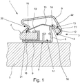
- Fig. 1 shows an embodiment of a flood protection system 1 in the assembled state in a sectional view.
- the flood protection system 1 is used for at least partially closing one in the 4 to 6 shown building opening 2, according to 4 to 6 a window.
- a first retaining rail 3a and second retaining rail 3b comprises. Between the first retaining rail 3a and the second retaining rail 3b, a protective plate 4 is held by the retaining rails 3.
- Fig. 1 shows a retaining rail 3 in mounted on a wall 5 in the region of a building opening state.
- the retaining rail 3 comprises a base profile 6, which has a contact surface 7, wherein the base profile 6 rests with the contact surface 7 on the wall 5 of the building. Between contact surface 7 and the wall 5 a gasket 8 is arranged.
- the base profile 6 is bolted to the wall 5, whereby the retaining rail 3 is fixed to the wall 5.
- the support rail 3 further comprises a cover profile 9 and a spring element 10.
- the cover profile 9 is pivotally held on the base profile 6, so that it is held between an open position and a closed position in the longitudinal direction pivotally mounted on the base profile 6. According to Fig. 1 Panning is done in the direction of the opening area in a clockwise direction.
- a longitudinally extending circular cylindrical guide shaft 11 is formed on the base profile 6, on which a provided on the cover profile 9 half-shell-shaped guide groove 12 is mounted.
- the movement of the cover profile 9 between the open position and the closed position is limited by the edge regions 13 of the half-shell-shaped guide groove 12.
- the cover profile 9 is according to Fig. 1 almost completely in the closed position and is urged by the spring element 10 in the closed position and thus against the protective plate 4.
- the spring element 10 is formed in this embodiment as a leaf spring and is arranged between the base profile 6 and the cover profile 9, that the spring element 10, the cover profile 9 from a predetermined pivot angle, but in particular in the illustrated position, urges into the closed position. Consequently, the spring element 10 causes a rotational movement of the cover profile 9 about the guide axis 11, so that in the present case a force is exerted on the protective plate 4.
- the spring element 10 in the form of a leaf spring cooperates in a first side region 14 with the base profile 6 and in a second side region 15 with the cover profile 9.
- the spring element 10 in the form of the leaf spring is substantially rectangular.
- the spring element 10 is held movably in a bearing groove 16 in the first side region 14.
- the bearing groove 16 has a substantially ⁇ -shaped cross-section.
- the spring element 10 in the form of the leaf spring is arranged in the bent state between the base profile 6 and the cover profile 9, so that always a spring force between the base profile 6 and cover profile 9 is applied.
- the protective plate 4 is clamped in the state shown under the action of the spring element 10 between the cover profile 9 and the base profile 6.
- the base profile 6 has a substantially rectangular receiving means 17 in this embodiment, which is formed as a rectangular channel.
- this receiving means 17 a - not shown - rectangular corner connector for connecting two retaining rails 3 can be inserted.
- the base profile 6 has a contact web 18, which causes the protective plate 4 between base profile 6 and cover profile 9 can be clamped. Between the contact web 18 and the protective plate 4, a seal 19 is also provided, which is formed in this embodiment substantially U-shaped and is pushed onto the protective plate 4 in the edge region. By the seal 19, a passage of water in the region of the retaining rail 3 is prevented.
- the cover profile 9 has a recessed grip 20 which is provided over the entire longitudinal extent of the cover profile 9.
- the recessed grip 20 can be gripped by a user in a simple manner and the cover profile 9 can be pivoted against the spring force of the spring element 10.
- Fig. 2 shows an embodiment of a support rail 3 - according to Fig. 1 - In a swivel angle between the open position and closed position, tends to be more towards the closed position.
- the spring element 10 urges at this pivot angle the cover profile 9 in the direction of the closed position, since no protective plate is arranged.
- Fig. 3a shows an embodiment of a cover profile 9 in a sectional view.
- the cover profile 9 has a recessed grip 20 for pivoting the cover profile 9 from a closed position to an open position or vice versa.
- the illustrated cover profile 9 comprises a half-shell-shaped guide groove 12 and a spring groove 21, in the - Fig. 1 and 2 -
- the second side portion 15 of a spring element 10 is arranged.
- Fig. 3b shows an embodiment of a base profile 6 in a sectional view.
- the base profile 6 has a guide axis 11, which is held by a web 22 on the base profile 6.
- the base profile 6 also has a receiving means 17 in the form of a unilaterally open, substantially rectangular channel.
- a contact web 18 is provided, which increases the contact surface 7 and also pinching a - in Fig. 1 shown - protection plate 4 between a cover profile 9 and the contact web 18 of the base profile 6 under the action of the spring force of the spring element 10 allows.
- Fig. 4 shows - as already stated - an embodiment of a flood protection system 1 in the assembled state before a building opening 2.
- the first support rail 3a and the second support rail 3b are bolted to the wall 5 right and left of the building openings 2 and parallel to each other.
- the protective plate 4 is clamped below the cover profiles 9.
- a Seal 23 is provided which prevents ingress of water in the lower region of the protective plate 4.
- Fig. 5 shows an embodiment of a flood protection system 1 with a first support rail 3a, a second support rail 3b and a third support rail 3c.
- the three retaining rails 3 are arranged in a U-shape relative to one another, so that the protective plate 4 is surrounded on three side edges by a respective retaining rail 3.
- the support rails 3 are fixed to the wall 5 around the building opening 2 around.
- Fig. 6 shows an embodiment of a flood protection system 1 with a first support rail 3a, a second support rail 3b, a third support rail 3c and a fourth support rail 3d.
- All four support rails 3 are arranged like a frame around the protective plate 4 around, so that the protective plate 4 along its entire circumference - all side edges - stabilized and sealed by the support rails 3.
- All cover profiles 9 of the support rails 3 exert a force on the protective plate 4, so that it is reliably held in position in front of the building opening.
- the support rails 3 form a closed frame around the building opening.
- the building opening is behind the flood protection system 1 and is completely closed.
Landscapes
- Engineering & Computer Science (AREA)
- Architecture (AREA)
- Structural Engineering (AREA)
- Civil Engineering (AREA)
- Business, Economics & Management (AREA)
- Emergency Management (AREA)
- Environmental & Geological Engineering (AREA)
- Specific Sealing Or Ventilating Devices For Doors And Windows (AREA)
Priority Applications (1)
| Application Number | Priority Date | Filing Date | Title |
|---|---|---|---|
| PL14194577T PL2876245T3 (pl) | 2013-11-22 | 2014-11-24 | Szyna mocująca do systemu przeciwpowodziowego |
Applications Claiming Priority (2)
| Application Number | Priority Date | Filing Date | Title |
|---|---|---|---|
| DE202013105343 | 2013-11-22 | ||
| DE201420100290 DE202014100290U1 (de) | 2013-11-22 | 2014-01-23 | Hochwasserschutzsystem |
Publications (2)
| Publication Number | Publication Date |
|---|---|
| EP2876245A1 EP2876245A1 (de) | 2015-05-27 |
| EP2876245B1 true EP2876245B1 (de) | 2017-05-03 |
Family
ID=50276768
Family Applications (1)
| Application Number | Title | Priority Date | Filing Date |
|---|---|---|---|
| EP14194577.4A Not-in-force EP2876245B1 (de) | 2013-11-22 | 2014-11-24 | Halteschiene für ein Hochwasserschutzsystem |
Country Status (3)
| Country | Link |
|---|---|
| EP (1) | EP2876245B1 (pl) |
| DE (1) | DE202014100290U1 (pl) |
| PL (1) | PL2876245T3 (pl) |
Families Citing this family (2)
| Publication number | Priority date | Publication date | Assignee | Title |
|---|---|---|---|---|
| DE202016106801U1 (de) | 2016-12-07 | 2018-03-09 | Hermann Reitthaler | Vorrichtung gegen das Eindringen von Flüssigkeit |
| DE102016123641A1 (de) | 2016-12-07 | 2018-06-07 | Hermann Reitthaler | Vorrichtung gegen das Eindringen von Flüssigkeiten |
Family Cites Families (3)
| Publication number | Priority date | Publication date | Assignee | Title |
|---|---|---|---|---|
| DE9213822U1 (de) * | 1992-10-14 | 1992-12-10 | C.F. Ploucquet GmbH & Co, 7920 Heidenheim | Abdichtvorrichtung in Gebäuden zum Korrosionsschutz |
| DE10233283C1 (de) * | 2002-07-23 | 2003-08-21 | Rainer Gross | Hochwasserschutzsystem |
| DE202010015708U1 (de) * | 2010-11-20 | 2011-01-27 | Kiegeland, Herbert | Hochwasserschutzrahmen |
-
2014
- 2014-01-23 DE DE201420100290 patent/DE202014100290U1/de not_active Expired - Lifetime
- 2014-11-24 EP EP14194577.4A patent/EP2876245B1/de not_active Not-in-force
- 2014-11-24 PL PL14194577T patent/PL2876245T3/pl unknown
Non-Patent Citations (1)
| Title |
|---|
| None * |
Also Published As
| Publication number | Publication date |
|---|---|
| DE202014100290U1 (de) | 2014-02-20 |
| EP2876245A1 (de) | 2015-05-27 |
| PL2876245T3 (pl) | 2017-11-30 |
Similar Documents
| Publication | Publication Date | Title |
|---|---|---|
| EP3221540B1 (de) | Dichtungsvorrichtung für einen verschiebbaren flügel als schiebeflügel oder verschiebbaren hebe-schiebeflügel eines fensters oder einer tür | |
| DE3212110A1 (de) | Verschiebbares tuer- und fensterelement | |
| EP0841456B1 (de) | Lamellenfenster für im wesentlichen senkrechte Fassaden | |
| EP2631414B1 (de) | Führungsschiene für Senkrechtmarkise und Senkrechtmarkise | |
| EP3241974B1 (de) | Anordnung für eine dichtung, insbesondere für eine auflaufdichtung oder für eine sich selbsttätig absenkende bodendichtung für türen | |
| EP4098836B1 (de) | Sektionaltor | |
| EP2947227B1 (de) | Wohndachfenster mit abdeckrahmenblech | |
| EP2876245A1 (de) | Hochwasserschutzsystem | |
| EP2063050B1 (de) | Schutzvorrichtung zur Absperrung von Fenster- oder Türöffnungen gegen spritzende, fließende, stehende und drückende flüssige bis zähfließende Medien | |
| AT512327B1 (de) | Hebe/schiebetür | |
| EP2395196B1 (de) | Vorsatztür, insbesondere Insektenschutztür, mit einem höhenverstellbaren Rollenlager | |
| DE102013112761A1 (de) | Haltevorrichtung für ein Gehäuse und Verfahren zur Montage des Gehäuses unter Verwendung der Haltevorrichtung | |
| EP1992756A2 (de) | Lamellendach | |
| DE102007007564A1 (de) | Hochwasserschutzvorrichtung | |
| DE102020108412A1 (de) | Extrudiertes Fenster- oder Tür-Hohlkammerprofil, System mit einem solchen Hohlkammerprofil und daraus hergestellter Rahmen | |
| EP1251234B1 (de) | Türdichtung | |
| DE102006026366A1 (de) | Hochwasserschutz-Vorrichtung | |
| EP2436848B1 (de) | Tragwerkkonstruktion | |
| DE202009013622U1 (de) | Winkelformteil für Kabelkanäle | |
| EP1947286B1 (de) | Rolladenkasten | |
| DE3520577C2 (de) | Elektromechanische Sicherheitskontaktleiste für kraftbetätigte Tore | |
| DE102007023008B3 (de) | Lamellendach | |
| DE102016111410A1 (de) | Mittelstütze für eine Gebäudeöffnung mit großer lichter Breite | |
| EP3168405B1 (de) | Rahmenkonstruktion für eine schiebetüre | |
| AT510161B1 (de) | Vorrichtung zur verbindung von wandteilen |
Legal Events
| Date | Code | Title | Description |
|---|---|---|---|
| PUAI | Public reference made under article 153(3) epc to a published international application that has entered the european phase |
Free format text: ORIGINAL CODE: 0009012 |
|
| 17P | Request for examination filed |
Effective date: 20141124 |
|
| AK | Designated contracting states |
Kind code of ref document: A1 Designated state(s): AL AT BE BG CH CY CZ DE DK EE ES FI FR GB GR HR HU IE IS IT LI LT LU LV MC MK MT NL NO PL PT RO RS SE SI SK SM TR |
|
| AX | Request for extension of the european patent |
Extension state: BA ME |
|
| R17P | Request for examination filed (corrected) |
Effective date: 20150610 |
|
| RBV | Designated contracting states (corrected) |
Designated state(s): AL AT BE BG CH CY CZ DE DK EE ES FI FR GB GR HR HU IE IS IT LI LT LU LV MC MK MT NL NO PL PT RO RS SE SI SK SM TR |
|
| GRAP | Despatch of communication of intention to grant a patent |
Free format text: ORIGINAL CODE: EPIDOSNIGR1 |
|
| STAA | Information on the status of an ep patent application or granted ep patent |
Free format text: STATUS: GRANT OF PATENT IS INTENDED |
|
| GRAS | Grant fee paid |
Free format text: ORIGINAL CODE: EPIDOSNIGR3 |
|
| RIC1 | Information provided on ipc code assigned before grant |
Ipc: E04H 9/14 20060101ALI20170103BHEP Ipc: E06B 9/00 20060101AFI20170103BHEP Ipc: E06B 9/02 20060101ALI20170103BHEP |
|
| GRAJ | Information related to disapproval of communication of intention to grant by the applicant or resumption of examination proceedings by the epo deleted |
Free format text: ORIGINAL CODE: EPIDOSDIGR1 |
|
| GRAL | Information related to payment of fee for publishing/printing deleted |
Free format text: ORIGINAL CODE: EPIDOSDIGR3 |
|
| STAA | Information on the status of an ep patent application or granted ep patent |
Free format text: STATUS: REQUEST FOR EXAMINATION WAS MADE |
|
| INTG | Intention to grant announced |
Effective date: 20170126 |
|
| GRAP | Despatch of communication of intention to grant a patent |
Free format text: ORIGINAL CODE: EPIDOSNIGR1 |
|
| STAA | Information on the status of an ep patent application or granted ep patent |
Free format text: STATUS: GRANT OF PATENT IS INTENDED |
|
| INTC | Intention to grant announced (deleted) | ||
| GRAA | (expected) grant |
Free format text: ORIGINAL CODE: 0009210 |
|
| STAA | Information on the status of an ep patent application or granted ep patent |
Free format text: STATUS: THE PATENT HAS BEEN GRANTED |
|
| INTG | Intention to grant announced |
Effective date: 20170317 |
|
| AK | Designated contracting states |
Kind code of ref document: B1 Designated state(s): AL AT BE BG CH CY CZ DE DK EE ES FI FR GB GR HR HU IE IS IT LI LT LU LV MC MK MT NL NO PL PT RO RS SE SI SK SM TR |
|
| REG | Reference to a national code |
Ref country code: GB Ref legal event code: FG4D Free format text: NOT ENGLISH |
|
| REG | Reference to a national code |
Ref country code: AT Ref legal event code: REF Ref document number: 890204 Country of ref document: AT Kind code of ref document: T Effective date: 20170515 Ref country code: CH Ref legal event code: EP |
|
| REG | Reference to a national code |
Ref country code: IE Ref legal event code: FG4D Free format text: LANGUAGE OF EP DOCUMENT: GERMAN |
|
| REG | Reference to a national code |
Ref country code: DE Ref legal event code: R096 Ref document number: 502014003635 Country of ref document: DE |
|
| REG | Reference to a national code |
Ref country code: NL Ref legal event code: MP Effective date: 20170503 |
|
| REG | Reference to a national code |
Ref country code: LT Ref legal event code: MG4D |
|
| PG25 | Lapsed in a contracting state [announced via postgrant information from national office to epo] |
Ref country code: HR Free format text: LAPSE BECAUSE OF FAILURE TO SUBMIT A TRANSLATION OF THE DESCRIPTION OR TO PAY THE FEE WITHIN THE PRESCRIBED TIME-LIMIT Effective date: 20170503 Ref country code: GR Free format text: LAPSE BECAUSE OF FAILURE TO SUBMIT A TRANSLATION OF THE DESCRIPTION OR TO PAY THE FEE WITHIN THE PRESCRIBED TIME-LIMIT Effective date: 20170804 Ref country code: NO Free format text: LAPSE BECAUSE OF FAILURE TO SUBMIT A TRANSLATION OF THE DESCRIPTION OR TO PAY THE FEE WITHIN THE PRESCRIBED TIME-LIMIT Effective date: 20170803 Ref country code: FI Free format text: LAPSE BECAUSE OF FAILURE TO SUBMIT A TRANSLATION OF THE DESCRIPTION OR TO PAY THE FEE WITHIN THE PRESCRIBED TIME-LIMIT Effective date: 20170503 Ref country code: ES Free format text: LAPSE BECAUSE OF FAILURE TO SUBMIT A TRANSLATION OF THE DESCRIPTION OR TO PAY THE FEE WITHIN THE PRESCRIBED TIME-LIMIT Effective date: 20170503 Ref country code: LT Free format text: LAPSE BECAUSE OF FAILURE TO SUBMIT A TRANSLATION OF THE DESCRIPTION OR TO PAY THE FEE WITHIN THE PRESCRIBED TIME-LIMIT Effective date: 20170503 |
|
| REG | Reference to a national code |
Ref country code: FR Ref legal event code: PLFP Year of fee payment: 4 |
|
| PG25 | Lapsed in a contracting state [announced via postgrant information from national office to epo] |
Ref country code: LV Free format text: LAPSE BECAUSE OF FAILURE TO SUBMIT A TRANSLATION OF THE DESCRIPTION OR TO PAY THE FEE WITHIN THE PRESCRIBED TIME-LIMIT Effective date: 20170503 Ref country code: IS Free format text: LAPSE BECAUSE OF FAILURE TO SUBMIT A TRANSLATION OF THE DESCRIPTION OR TO PAY THE FEE WITHIN THE PRESCRIBED TIME-LIMIT Effective date: 20170903 Ref country code: RS Free format text: LAPSE BECAUSE OF FAILURE TO SUBMIT A TRANSLATION OF THE DESCRIPTION OR TO PAY THE FEE WITHIN THE PRESCRIBED TIME-LIMIT Effective date: 20170503 Ref country code: NL Free format text: LAPSE BECAUSE OF FAILURE TO SUBMIT A TRANSLATION OF THE DESCRIPTION OR TO PAY THE FEE WITHIN THE PRESCRIBED TIME-LIMIT Effective date: 20170503 Ref country code: SE Free format text: LAPSE BECAUSE OF FAILURE TO SUBMIT A TRANSLATION OF THE DESCRIPTION OR TO PAY THE FEE WITHIN THE PRESCRIBED TIME-LIMIT Effective date: 20170503 Ref country code: BG Free format text: LAPSE BECAUSE OF FAILURE TO SUBMIT A TRANSLATION OF THE DESCRIPTION OR TO PAY THE FEE WITHIN THE PRESCRIBED TIME-LIMIT Effective date: 20170803 |
|
| REG | Reference to a national code |
Ref country code: HU Ref legal event code: AG4A Ref document number: E033965 Country of ref document: HU |
|
| PG25 | Lapsed in a contracting state [announced via postgrant information from national office to epo] |
Ref country code: SK Free format text: LAPSE BECAUSE OF FAILURE TO SUBMIT A TRANSLATION OF THE DESCRIPTION OR TO PAY THE FEE WITHIN THE PRESCRIBED TIME-LIMIT Effective date: 20170503 Ref country code: DK Free format text: LAPSE BECAUSE OF FAILURE TO SUBMIT A TRANSLATION OF THE DESCRIPTION OR TO PAY THE FEE WITHIN THE PRESCRIBED TIME-LIMIT Effective date: 20170503 Ref country code: EE Free format text: LAPSE BECAUSE OF FAILURE TO SUBMIT A TRANSLATION OF THE DESCRIPTION OR TO PAY THE FEE WITHIN THE PRESCRIBED TIME-LIMIT Effective date: 20170503 Ref country code: RO Free format text: LAPSE BECAUSE OF FAILURE TO SUBMIT A TRANSLATION OF THE DESCRIPTION OR TO PAY THE FEE WITHIN THE PRESCRIBED TIME-LIMIT Effective date: 20170503 |
|
| REG | Reference to a national code |
Ref country code: DE Ref legal event code: R097 Ref document number: 502014003635 Country of ref document: DE |
|
| PG25 | Lapsed in a contracting state [announced via postgrant information from national office to epo] |
Ref country code: IT Free format text: LAPSE BECAUSE OF FAILURE TO SUBMIT A TRANSLATION OF THE DESCRIPTION OR TO PAY THE FEE WITHIN THE PRESCRIBED TIME-LIMIT Effective date: 20170503 Ref country code: SM Free format text: LAPSE BECAUSE OF FAILURE TO SUBMIT A TRANSLATION OF THE DESCRIPTION OR TO PAY THE FEE WITHIN THE PRESCRIBED TIME-LIMIT Effective date: 20170503 |
|
| PLBE | No opposition filed within time limit |
Free format text: ORIGINAL CODE: 0009261 |
|
| STAA | Information on the status of an ep patent application or granted ep patent |
Free format text: STATUS: NO OPPOSITION FILED WITHIN TIME LIMIT |
|
| 26N | No opposition filed |
Effective date: 20180206 |
|
| PG25 | Lapsed in a contracting state [announced via postgrant information from national office to epo] |
Ref country code: SI Free format text: LAPSE BECAUSE OF FAILURE TO SUBMIT A TRANSLATION OF THE DESCRIPTION OR TO PAY THE FEE WITHIN THE PRESCRIBED TIME-LIMIT Effective date: 20170503 |
|
| PG25 | Lapsed in a contracting state [announced via postgrant information from national office to epo] |
Ref country code: MC Free format text: LAPSE BECAUSE OF FAILURE TO SUBMIT A TRANSLATION OF THE DESCRIPTION OR TO PAY THE FEE WITHIN THE PRESCRIBED TIME-LIMIT Effective date: 20170503 |
|
| PG25 | Lapsed in a contracting state [announced via postgrant information from national office to epo] |
Ref country code: CH Free format text: LAPSE BECAUSE OF NON-PAYMENT OF DUE FEES Effective date: 20171130 Ref country code: LI Free format text: LAPSE BECAUSE OF NON-PAYMENT OF DUE FEES Effective date: 20171130 |
|
| PG25 | Lapsed in a contracting state [announced via postgrant information from national office to epo] |
Ref country code: LU Free format text: LAPSE BECAUSE OF NON-PAYMENT OF DUE FEES Effective date: 20171124 |
|
| REG | Reference to a national code |
Ref country code: BE Ref legal event code: MM Effective date: 20171130 |
|
| REG | Reference to a national code |
Ref country code: IE Ref legal event code: MM4A |
|
| PG25 | Lapsed in a contracting state [announced via postgrant information from national office to epo] |
Ref country code: MT Free format text: LAPSE BECAUSE OF FAILURE TO SUBMIT A TRANSLATION OF THE DESCRIPTION OR TO PAY THE FEE WITHIN THE PRESCRIBED TIME-LIMIT Effective date: 20170503 |
|
| PG25 | Lapsed in a contracting state [announced via postgrant information from national office to epo] |
Ref country code: IE Free format text: LAPSE BECAUSE OF NON-PAYMENT OF DUE FEES Effective date: 20171124 |
|
| PG25 | Lapsed in a contracting state [announced via postgrant information from national office to epo] |
Ref country code: BE Free format text: LAPSE BECAUSE OF NON-PAYMENT OF DUE FEES Effective date: 20171130 |
|
| PGFP | Annual fee paid to national office [announced via postgrant information from national office to epo] |
Ref country code: HU Payment date: 20181203 Year of fee payment: 5 |
|
| PGFP | Annual fee paid to national office [announced via postgrant information from national office to epo] |
Ref country code: GB Payment date: 20181120 Year of fee payment: 5 Ref country code: FR Payment date: 20181123 Year of fee payment: 5 |
|
| PGFP | Annual fee paid to national office [announced via postgrant information from national office to epo] |
Ref country code: DE Payment date: 20190116 Year of fee payment: 5 |
|
| PG25 | Lapsed in a contracting state [announced via postgrant information from national office to epo] |
Ref country code: CY Free format text: LAPSE BECAUSE OF FAILURE TO SUBMIT A TRANSLATION OF THE DESCRIPTION OR TO PAY THE FEE WITHIN THE PRESCRIBED TIME-LIMIT Effective date: 20170503 |
|
| PG25 | Lapsed in a contracting state [announced via postgrant information from national office to epo] |
Ref country code: MK Free format text: LAPSE BECAUSE OF FAILURE TO SUBMIT A TRANSLATION OF THE DESCRIPTION OR TO PAY THE FEE WITHIN THE PRESCRIBED TIME-LIMIT Effective date: 20170503 |
|
| PGFP | Annual fee paid to national office [announced via postgrant information from national office to epo] |
Ref country code: CZ Payment date: 20191122 Year of fee payment: 6 |
|
| PGFP | Annual fee paid to national office [announced via postgrant information from national office to epo] |
Ref country code: PL Payment date: 20191022 Year of fee payment: 6 |
|
| PG25 | Lapsed in a contracting state [announced via postgrant information from national office to epo] |
Ref country code: TR Free format text: LAPSE BECAUSE OF FAILURE TO SUBMIT A TRANSLATION OF THE DESCRIPTION OR TO PAY THE FEE WITHIN THE PRESCRIBED TIME-LIMIT Effective date: 20170503 |
|
| PG25 | Lapsed in a contracting state [announced via postgrant information from national office to epo] |
Ref country code: PT Free format text: LAPSE BECAUSE OF FAILURE TO SUBMIT A TRANSLATION OF THE DESCRIPTION OR TO PAY THE FEE WITHIN THE PRESCRIBED TIME-LIMIT Effective date: 20170503 |
|
| REG | Reference to a national code |
Ref country code: DE Ref legal event code: R119 Ref document number: 502014003635 Country of ref document: DE |
|
| PG25 | Lapsed in a contracting state [announced via postgrant information from national office to epo] |
Ref country code: AL Free format text: LAPSE BECAUSE OF FAILURE TO SUBMIT A TRANSLATION OF THE DESCRIPTION OR TO PAY THE FEE WITHIN THE PRESCRIBED TIME-LIMIT Effective date: 20170503 |
|
| PG25 | Lapsed in a contracting state [announced via postgrant information from national office to epo] |
Ref country code: HU Free format text: LAPSE BECAUSE OF NON-PAYMENT OF DUE FEES Effective date: 20191125 |
|
| GBPC | Gb: european patent ceased through non-payment of renewal fee |
Effective date: 20191124 |
|
| PG25 | Lapsed in a contracting state [announced via postgrant information from national office to epo] |
Ref country code: DE Free format text: LAPSE BECAUSE OF NON-PAYMENT OF DUE FEES Effective date: 20200603 Ref country code: FR Free format text: LAPSE BECAUSE OF NON-PAYMENT OF DUE FEES Effective date: 20191130 Ref country code: GB Free format text: LAPSE BECAUSE OF NON-PAYMENT OF DUE FEES Effective date: 20191124 |
|
| REG | Reference to a national code |
Ref country code: AT Ref legal event code: MM01 Ref document number: 890204 Country of ref document: AT Kind code of ref document: T Effective date: 20191124 |
|
| PG25 | Lapsed in a contracting state [announced via postgrant information from national office to epo] |
Ref country code: AT Free format text: LAPSE BECAUSE OF NON-PAYMENT OF DUE FEES Effective date: 20191124 |
|
| PG25 | Lapsed in a contracting state [announced via postgrant information from national office to epo] |
Ref country code: CZ Free format text: LAPSE BECAUSE OF NON-PAYMENT OF DUE FEES Effective date: 20201124 |
|
| PG25 | Lapsed in a contracting state [announced via postgrant information from national office to epo] |
Ref country code: PL Free format text: LAPSE BECAUSE OF NON-PAYMENT OF DUE FEES Effective date: 20201124 |