EP2876231A1 - Verteilerkasten für Beton-Mauern und -Bodenplatten - Google Patents
Verteilerkasten für Beton-Mauern und -Bodenplatten Download PDFInfo
- Publication number
- EP2876231A1 EP2876231A1 EP14194174.0A EP14194174A EP2876231A1 EP 2876231 A1 EP2876231 A1 EP 2876231A1 EP 14194174 A EP14194174 A EP 14194174A EP 2876231 A1 EP2876231 A1 EP 2876231A1
- Authority
- EP
- European Patent Office
- Prior art keywords
- reservation box
- panel
- box according
- reservation
- panels
- Prior art date
- Legal status (The legal status is an assumption and is not a legal conclusion. Google has not performed a legal analysis and makes no representation as to the accuracy of the status listed.)
- Pending
Links
Images


Classifications
-
- E—FIXED CONSTRUCTIONS
- E04—BUILDING
- E04G—SCAFFOLDING; FORMS; SHUTTERING; BUILDING IMPLEMENTS OR AIDS, OR THEIR USE; HANDLING BUILDING MATERIALS ON THE SITE; REPAIRING, BREAKING-UP OR OTHER WORK ON EXISTING BUILDINGS
- E04G15/00—Forms or shutterings for making openings, cavities, slits, or channels
- E04G15/06—Forms or shutterings for making openings, cavities, slits, or channels for cavities or channels in walls of floors, e.g. for making chimneys
- E04G15/061—Non-reusable forms
-
- B—PERFORMING OPERATIONS; TRANSPORTING
- B28—WORKING CEMENT, CLAY, OR STONE
- B28B—SHAPING CLAY OR OTHER CERAMIC COMPOSITIONS; SHAPING SLAG; SHAPING MIXTURES CONTAINING CEMENTITIOUS MATERIAL, e.g. PLASTER
- B28B7/00—Moulds; Cores; Mandrels
- B28B7/0002—Auxiliary parts or elements of the mould
- B28B7/0014—Fastening means for mould parts, e.g. for attaching mould walls on mould tables; Mould clamps
- B28B7/0017—Fastening means for mould parts, e.g. for attaching mould walls on mould tables; Mould clamps for attaching mould walls on mould tables
-
- B—PERFORMING OPERATIONS; TRANSPORTING
- B28—WORKING CEMENT, CLAY, OR STONE
- B28B—SHAPING CLAY OR OTHER CERAMIC COMPOSITIONS; SHAPING SLAG; SHAPING MIXTURES CONTAINING CEMENTITIOUS MATERIAL, e.g. PLASTER
- B28B7/00—Moulds; Cores; Mandrels
- B28B7/16—Moulds for making shaped articles with cavities or holes open to the surface, e.g. with blind holes
- B28B7/18—Moulds for making shaped articles with cavities or holes open to the surface, e.g. with blind holes the holes passing completely through the article
- B28B7/186—Moulds for making shaped articles with cavities or holes open to the surface, e.g. with blind holes the holes passing completely through the article for plates, panels or similar sheet- or disc-shaped objects, also flat oblong moulded articles with lateral openings, e.g. panels with openings for doors or windows, grated girders
Definitions
- the present invention relates to the field of construction of buildings or any concrete structure and aims at the realization of a reservation box.
- a formwork is prepared, in which empty volumes are provided for the passage of cables, pipes and other pipes in order to avoid having to drill the wall or the slab after their completion.
- so-called reservation boxes are incorporated before the pouring stage of the concrete.
- Known reservation boxes are generally made of wood, cellular plastic or expanded polystyrene, the latter material being however less and less used for ecological reasons.
- the wooden reservation boxes are usually made with formwork wood panels and assembled on site, a time-consuming operation.
- Some booking boxes, made of cellular plastic, are delivered on-site, reducing manufacturing costs on site but generating significant transportation and storage costs.
- the box of reservation consists of angular elements, that is to say with a square shape, each constituting at least two adjacent portions of two perpendicular faces of the contour of the reservation box when four angular elements are used, or even constituting each integrally two perpendicular faces adjacent to the contour of this reservation box when only two angular elements are used.
- Tabs arranged on the lateral edge of a first angular element can adopt a so-called “sliding" position to be inserted in slots arranged on the lateral edge of an adjacent substantially perpendicular angular element, or a "locked” deformed position in which they maintain the adjacent angular elements assembled with each other.
- This design has the disadvantage of not optimizing the space requirement of the reservation box in storage position, which generates additional costs of transport on the sites.
- the tabs being in the locked position, it has sealing defects at the junction edges between the angular elements. Concrete can therefore enter the reservation box when it is poured or even after pouring.
- the present invention aims to remedy the aforementioned drawbacks and to provide a solution to the problems specific to predalles.
- the reservation box includes a waist wall that is composed of four panels forming a substantially parallelepipedal cavity, the panels being assembled and held together by means of projections and slots.
- the projecting portions may adopt a so-called sliding position in which they can be inserted into the respective slots of an adjacent substantially perpendicular panel, and a so-called locked deformed position in which they maintain the two adjacent perpendicular panels in contact with each other. other.
- the shape of the protruding portions is configured at least to bring said adjacent perpendicular panels closer to each other in the locked position.
- the projecting portions are also configured to prevent vertical movement between adjacent panels in the locked position.
- the protruding parts have a geometry having an inclined inner edge that extends beyond a straight line delimiting the outer or lateral edge of the panel.
- each panel comprises along its lower edge an inwardly directed flange configured to support a bottom wall.
- each inwardly directed flange has one or more holes.
- each panel includes one or more deformable downward zones which are positioned so that the edges of said downwardly deformable zones are substantially coplanar and which, when deformed inwardly, the cavity, keep the bottom wall substantially in contact with the inwardly directed flange.
- each panel has an outwardly directed flange situated along one or both of its edges that does not already include an inwardly directed rim as defined in FIG. the aforementioned embodiment.
- each panel comprises a set of upwardly deformable zones, these deformable zones being positioned in such a way that, when they are deformed towards the inside of the cavity, they can support a cover by ensuring that the upper surface of said cover is substantially coplanar with the upper edge of said panel.
- each panel has along its upper edge an L-shaped rim directed towards the outside of the cavity and supporting a lid.
- each panel comprises a set of upwardly deformable zones which can be deformed inwards. of the cavity to each form a V-shaped support for a lower edge without flange of four panels of an upper reservation box having at least the features object of the invention, the upper reservation box having dimensions slightly lower than those of the lower reservation box so as to be able to slide along the panels of the latter to the V-shaped supports.
- each panel comprises two or more sets of upwardly deformable zones. at different heights relative to the lower edge of said panel.
- each panel comprises one or more deformable zones downwards and one or more upwardly deformable zones positioned so as to cooperate to maintain, in their deformed position towards the inside. of the cavity, an intermediate wall.
- each panel comprises several sets of two sets of deformable zones downwards and upwardly deformable zones, to maintain a plurality of intermediate walls inside the cavity.
- the material used for the panels is metal sheet. This reduces the weight and bulk of the panels.
- the sheet used has a thickness such that the parts and areas intended to be deformed can be manually, without requiring tools.
- each panel has one or more longitudinal V-shaped deformations.
- the reservation box comprises at least four independent lateral panels, preferably of thin metal sheet, which are fixed together so as to form a substantially parallelepipedal cavity.
- the fixing solution uses protruding parts, also called tabs in the following description, which are made in the extension of a first outer or lateral edge of the panels and which are inserted into corresponding slots of a second outer edge or side panels opposite to the first side edge, said panels being perpendicular and adjacent to each other.
- protruding parts and these slots can be arranged in the planes of the panels or perpendicular to the planes of the panels, at their lateral edges.
- the protrusions are deformed by hand after insertion into the respective slots, in a position preventing the tab from being pulled out of the slot so as to maintain the adjacent panels in a position substantially perpendicular to each other.
- the particular shape of the tongues offers two additional advantages: when the tongues are deformed after insertion, this shape makes it possible to bring the adjacent perpendicular panels closer to each other, which are thus pressed against each other; and when the tabs are opposed to the first side edge of the panel, their shape prevents vertical movement of one panel relative to the other.
- the assembly of the panels to form the cavity is very fast and does not require tools.
- the assembled panels can be easily disassembled to dismantle the reservation box and store it in a less bulky form, as long as the concrete has not been poured around.
- said tongues and slots are in the plane of the panels, said tongues are deformed so as to remain substantially perpendicular to the adjacent panel in order to provide an additional anchoring zone in the concrete which will be cast around the reservation box.
- the reservation box may also include a bottom wall, which preferably rests on a flange made by bending 90 ° inwardly of the cavity of the lower edge of each of the side panels.
- This bottom wall also makes it possible to stiffen the waist wall formed by the four panels and to retain the substantially parallelepipedal shape of the cavity during manipulations of the reservation box and / or the pouring of the concrete.
- It can be made of a material such as cardboard, wood or a cellular synthetic material or not, the preferred material however being the synthetic cellular material called PPB, which can be easily pierced by means of a hole saw to pass the pipes and pipes while being lightweight and offering sufficient rigidity to support the filling concrete which will be poured later to seal the cavity for thermal and sound insulation.
- the bottom wall may advantageously be held in position against the lower flange by means of deformable zones oriented downwards and made in each of the side panels. These areas can be deformed by hand, without the need for tools.
- the bottom wall is either placed freely on the lower rim, or held in position against this rim by the deformable areas by hand and can be replaced in the plane of the corresponding panel, it is possible to extract said wall from the bottom of the reservation box to make the cuts for the passage of pipes and pipes in more ergonomic conditions than when the bottom wall must be pierced in situ.
- such an extraction also allows easy duplication of cuts made in the bottom walls of all floors.
- the reservation box may also include a cover, which may help to stiffen the reservation box.
- This cover can advantageously be placed on an L-shaped edge obtained by folding the upper edge of each of the side panels.
- the lid is centered on the reservation box by the L-shaped rim.
- a thick plate for example, a 25mm thick OSB board offering an optimal compromise between cost, weight, strength and recyclability
- the support offered by the metal panels prevents anyone from falling through the reservation box once the slab has been cast and the formwork removed, improving safety on the construction site.
- the OSB or wood (solid or formwork) cover may be cut and placed on the unused portion to prevent any fall through. the cavity.
- the reservation box provided with its cover provides a smooth and coplanar perfect surface with the upper surface of the poured concrete slab to allow in particular the passage of pallet trucks or other rolling machines.
- Another embodiment of the cover consists in inserting said cover inside the reservation box and resting it on upwardly deformable zones arranged in each of the side panels at a height such that the upper surface cover is coplanar with the upper edge of the reservation box.
- Another embodiment of the lid consists in producing in the lower part of the lid a groove in the dimensions of the rectangular section of the parallelepiped delimited by the reservation box. Said cover can then be placed directly on the upper edge of the panels of the reservation box, also contributing to stiffen it.
- metal sheets as a material for the side panels is that they can be left in place after the pouring of the slab concrete for buildings that meet firewall standards.
- the sheet metal gives panels a better mechanical strength than the booking boxes made of cellular synthetic material, which allows them to better withstand the pressure of the concrete during casting.
- the lateral metal sheet panels of the reservation box according to the invention may also comprise one or more longitudinal V-shaped deformations made in a direction substantially parallel to the free edges of the panel. These deformations increase the longitudinal stiffness of each panel of the belt wall and allow it to withstand the pressure of the concrete during casting without requiring additional reinforcing elements such as braces used in some boxes of cellular plastic. In addition, they increase the anchoring of the reservation box in the concrete located outside the box (slab or cast slab). In addition, they increase the anchoring of the poured filling concrete inside the box.
- the reservation box which is the subject of the invention can also be used in floors using prefabricated pre-slabs.
- a reservation box according to the invention is placed in the pre-slab formwork having a height identical to that of the predalle, with a bottom wall held in position between a lower flange and deformable areas facing downwards to prevent any loss of the bottom wall during transport and handling.
- the predalle set up on the site it is asked, on a set of deformable zones oriented upward of the pre-block reservation box and can be deformed towards the interior of the cavity to form a shaped support of V, a second reservation box devoid of lower rim and longitudinal V-shaped deformations, having dimensions slightly smaller than the predalle reservation box and formed with panels having the tongues and the insertion slots turned 90 ° to inside the cavity formed by the 4 assembled panels (U-shaped panels).
- the lower reservation box comprises a plurality of sets of deformable zones located at different heights relative to the bottom of the box (for example, every centimeter), in order to be able to vary the vertical position of the bearing zone of the upper reservation box and thus change the total height of the cavity defined by the two superimposed reservation boxes.
- This solution makes it possible to create reservation boxes of variable height with a single height of upper reservation box.
- the reservation boxes according to the invention can be held in their position by means of nails passing through the bottom wall at any places thereof, or at locations above a hole or a passage therefor in the lower rim, ie at places where the wall has been deformed downwards to keep the bottom wall in contact with the lower rim (the nails then being inclined towards the inside of the cavity).
- the reservation box according to the invention can also be used to make cavities in concrete walls (vertical walls), as described below.
- reservation box according to the invention can be delivered on site in the form of a low volume kit comprising the unmounted side panels, the cover and the bottom wall, resulting in thus savings in transport and storage.
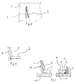
- the reservation box 1 illustrated in the figure 1 has four side panels 2 of thin metal sheet which are assembled to form a belt wall.
- the projecting parts, called tabs 3, of each panel are inserted into slots 4 of an adjacent panel placed substantially perpendicular, then the free end of the tongues is deformed about 1/8 of a turn around a coplanar axis with the panel bearing the tongues 3, as shown in FIG. figure 2 .
- the assembly of the four lateral panels delimits a cavity closed at its lower part by a removable bottom wall 6.
- the panels 2 comprise downwardly deformable zones 8 which are pushed manually into the cavity, with an angle ideally between 10 and about 30 degrees, as shown in figure 3 .
- the reservation box 1 thus formed is then positioned on the formwork at the desired location for the reservation. If necessary, and in the case of wooden formwork, it can be held in position on the wooden formwork panel 15 by means of nails 14, as illustrated in FIG. figure 4 .
- the nails 14 can be planted either at any point in the bottom wall, or through the holes 7 provided for this purpose in the inwardly directed flanges 5 or through the deformable zones 8 at an angle inclination allowing the nail 14 to go beyond the rim directed inwardly 5.
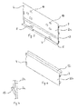
- a first reservation box 1a is assembled as described above and illustrated to the Figures 1 to 4 but with panels 2a devoid of an L-shaped flange 12 and having a plurality of upwardly deformable zone sets 10 at different heights, as illustrated in FIG. figure 5 .
- These upwardly deformable areas have the shape of a V in a deformed position towards the inside of the reservation box.
- the reservation box thus formed is held in position in the predalle manufactured in the factory by means of the tongues 3 and longitudinal V-shaped deformations 13 which are embedded in the concrete poured around the reservation box.
- a second reservation box 1b is assembled as described above and illustrated in FIGS. Figures 1 to 4 , but with panels 2b devoid of rim directed inwards, devoid of deformable zones downwards 8 and devoid of deformations longitudinal V-shaped 13, as illustrated in FIG. figure 6 .
- these panels 2b have a slightly shorter length than the panels 2a to allow the reservation box 1b to slide inside the reservation box 1a and to come against the set of deformable zones towards the a given height having been deformed towards the inside of the cavity to form a V, as illustrated in FIG. figure 7 .
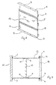
- FIGS. Figures 8 and 9 Another embodiment of the present invention is a concrete veil reservation box, illustrated in FIGS. Figures 8 and 9 .
- This reservation box is formed with panels 2 without an L-shaped flange 12, provided with outwardly directed flanges 9 on their lower and upper edges, and having upwardly deformable zones 10 placed slightly below the longitudinal median of the panel 2 and deformable areas downwardly 8 placed slightly above said longitudinal median, as illustrated in FIG. figure 8 .
- the booking box is assembled as described above and illustrated to Figures 1 to 4 except that the bottom wall is placed on the upwardly deformable zones deformed towards the inside of the cavity and is held in position by the deformable zones 8, which are also deformed towards the inside of the cavity. cavity, to form an intermediate wall 16.
- the reservation box thus produced is then rotated by 90 degrees so as to bring the intermediate wall 16 in a substantially vertical position, the former upper and lower openings then becoming lateral openings.
- the reservation box can then be nailed through the holes 7 to a vertically disposed wooden formwork panel 15, as shown in FIG. figure 9 .
- the invention makes it possible to manufacture a reservation box for concrete veil comprising at least two intermediate walls 16 instead of one, for example if it is desired to obtain a more rigid reservation box.
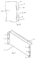
- FIGS. 10a, 10c, 11a and 11c show two embodiments of the tongue / slot assembly, respectively in their "sliding" position ( Figures 10a and 10c ) and “locked” ( Figures 11a and 11c ).
- the first embodiment of the tongue / slot assembly illustrated in figure 10a and 11a has a vertical slot 4a.
- the tongue 3a is inserted directly into the corresponding slot 4a ( figure 10a ), then the free part is turned around a coplanar axis with the panel 2 carrying the tongue 3a ( figure 11a ) to block the two panels against each other.
- the second embodiment of the tongue / slot assembly illustrated in Figures 10c and 11c , has a slot 4c formed of a substantially vertical portion 4c1 and a portion 4c2 forming an angle of about 5 to 45 degrees with the portion 4c1.
- each tab 3c is deformed by hand so that it can be inserted into the corresponding slot 4c, and then the tab 3c is again deformed to keep the two perpendicular panels in contact with each other, for example by putting the tongue 3c back to its original position.
- This form is also not the preferred embodiment as it involves more manipulation than the first embodiment of the tab / slot assembly.
- the figure 12 is a side view of the tongues 3 in the preferred embodiment illustrated in FIG. Figures 10a and 11a .
- the particular geometry of these tongues allows, when they are deformed after being inserted into the slots of an adjacent perpendicular panel, to press the two adjacent panels against each other, thus avoiding any entry of concrete into the reservation box.
- the four panels 2 of the reservation box 1 are pressed against each other, once all the tongues 3 locked in all the respective slots.
- the panels have at least two tabs 3 placed in opposition, as illustrated on the figure 12 this avoids any vertical displacement of one panel relative to another.
- This particular geometry of the tongues 3 can also be envisaged in the embodiment illustrated in FIG. Figures 10c and 11c .
- the figure 13 shows, in perspective, a panel for manufacturing a superior reservation box for insertion in a lower reservation box.
- the peculiarity of this panel is that the tongues 3 and the slots 4 are folded at 90 ° inwards with respect to the plane of the panel 2 (U-shaped) so as to be inside the cavity delimited by the four panels assembled together by means of said tongues 3 and slots 4.
- the thickness of the metal sheet of the panels 2, in the deformable zones downwards and upwards and at the level of the tongues 3 will be determined to allow their deformation manually, without the use of complementary tools, in order to facilitate the assembly and to reduce the assembly time of the reservation box.
Landscapes
- Engineering & Computer Science (AREA)
- Mechanical Engineering (AREA)
- Manufacturing & Machinery (AREA)
- Chemical & Material Sciences (AREA)
- Ceramic Engineering (AREA)
- Architecture (AREA)
- Civil Engineering (AREA)
- Structural Engineering (AREA)
- Forms Removed On Construction Sites Or Auxiliary Members Thereof (AREA)
Applications Claiming Priority (1)
| Application Number | Priority Date | Filing Date | Title |
|---|---|---|---|
| FR1361385A FR3013371B1 (fr) | 2013-11-20 | 2013-11-20 | Boite de reservation pour murs ou dalles de beton |
Publications (1)
| Publication Number | Publication Date |
|---|---|
| EP2876231A1 true EP2876231A1 (de) | 2015-05-27 |
Family
ID=50482916
Family Applications (1)
| Application Number | Title | Priority Date | Filing Date |
|---|---|---|---|
| EP14194174.0A Pending EP2876231A1 (de) | 2013-11-20 | 2014-11-20 | Verteilerkasten für Beton-Mauern und -Bodenplatten |
Country Status (2)
| Country | Link |
|---|---|
| EP (1) | EP2876231A1 (de) |
| FR (1) | FR3013371B1 (de) |
Cited By (5)
| Publication number | Priority date | Publication date | Assignee | Title |
|---|---|---|---|---|
| WO2018176091A1 (en) * | 2017-03-27 | 2018-10-04 | David Liebke | Penetration forming apparatus and method of use |
| EP3347548A4 (de) * | 2015-09-09 | 2019-05-22 | Walk Safe Innovations, LLC | Einbaubehälter zur erzeugung von perforationen in einer gegossenen betondecken und verfahren zur verwendung |
| AU2018100374B4 (en) * | 2018-03-27 | 2019-12-05 | Masterform Systems Pty Ltd | Formwork for Creating Penetrations or Openings in Concrete Floor Structures |
| CN112299868A (zh) * | 2020-10-23 | 2021-02-02 | 山东工业陶瓷研究设计院有限公司 | 一种薄壁异型C/SiC面板的制备方法 |
| GB2567916B (en) * | 2017-10-31 | 2022-09-28 | Abbey Pynford Holdings Ltd | A Retaining Barrier |
Families Citing this family (1)
| Publication number | Priority date | Publication date | Assignee | Title |
|---|---|---|---|---|
| US11479982B2 (en) * | 2019-10-04 | 2022-10-25 | Forrester Manufacturing Co., Inc. | Isolation pocket form and method for making crack resistant concrete slabs |
Citations (7)
| Publication number | Priority date | Publication date | Assignee | Title |
|---|---|---|---|---|
| US2483269A (en) * | 1946-06-24 | 1949-09-27 | American Machinery Corp | Field box |
| US2530849A (en) * | 1947-05-22 | 1950-11-21 | Ben F Louis | Beverage case |
| DE828220C (de) * | 1950-08-06 | 1952-01-17 | Fischer Eckert & Co | Zylindrischer Versandbehaelter aus Blech |
| CA881250A (en) * | 1964-06-17 | 1971-09-21 | Madeleine Charbonneau | Chimney base mold |
| DE9208868U1 (de) | 1992-07-02 | 1992-09-10 | Dietle, Hans, 7274 Haiterbach | Verlorene Schalung |
| EP0532067A1 (de) * | 1991-09-10 | 1993-03-17 | Kb-Produkter I Nybro Ab | Durchführung mit Abdeckung zum Einbetonieren |
| DE9302919U1 (de) * | 1993-02-27 | 1993-05-19 | Weckenmann Anlagentechnik GmbH, 7461 Dormettingen | Aussparungskörper für Betonfertigteile |
-
2013
- 2013-11-20 FR FR1361385A patent/FR3013371B1/fr active Active
-
2014
- 2014-11-20 EP EP14194174.0A patent/EP2876231A1/de active Pending
Patent Citations (7)
| Publication number | Priority date | Publication date | Assignee | Title |
|---|---|---|---|---|
| US2483269A (en) * | 1946-06-24 | 1949-09-27 | American Machinery Corp | Field box |
| US2530849A (en) * | 1947-05-22 | 1950-11-21 | Ben F Louis | Beverage case |
| DE828220C (de) * | 1950-08-06 | 1952-01-17 | Fischer Eckert & Co | Zylindrischer Versandbehaelter aus Blech |
| CA881250A (en) * | 1964-06-17 | 1971-09-21 | Madeleine Charbonneau | Chimney base mold |
| EP0532067A1 (de) * | 1991-09-10 | 1993-03-17 | Kb-Produkter I Nybro Ab | Durchführung mit Abdeckung zum Einbetonieren |
| DE9208868U1 (de) | 1992-07-02 | 1992-09-10 | Dietle, Hans, 7274 Haiterbach | Verlorene Schalung |
| DE9302919U1 (de) * | 1993-02-27 | 1993-05-19 | Weckenmann Anlagentechnik GmbH, 7461 Dormettingen | Aussparungskörper für Betonfertigteile |
Cited By (7)
| Publication number | Priority date | Publication date | Assignee | Title |
|---|---|---|---|---|
| EP3347548A4 (de) * | 2015-09-09 | 2019-05-22 | Walk Safe Innovations, LLC | Einbaubehälter zur erzeugung von perforationen in einer gegossenen betondecken und verfahren zur verwendung |
| US20190390471A1 (en) * | 2015-09-09 | 2019-12-26 | Walk Safe Innovations, Llc | Rough-in Box for Creating Penetrations in Poured Concrete Flooring and Method of Use |
| US10837183B2 (en) | 2015-09-09 | 2020-11-17 | Walk Safe Innovations, Llc | Rough-in box for creating penetrations in poured concrete flooring and method of use |
| WO2018176091A1 (en) * | 2017-03-27 | 2018-10-04 | David Liebke | Penetration forming apparatus and method of use |
| GB2567916B (en) * | 2017-10-31 | 2022-09-28 | Abbey Pynford Holdings Ltd | A Retaining Barrier |
| AU2018100374B4 (en) * | 2018-03-27 | 2019-12-05 | Masterform Systems Pty Ltd | Formwork for Creating Penetrations or Openings in Concrete Floor Structures |
| CN112299868A (zh) * | 2020-10-23 | 2021-02-02 | 山东工业陶瓷研究设计院有限公司 | 一种薄壁异型C/SiC面板的制备方法 |
Also Published As
| Publication number | Publication date |
|---|---|
| FR3013371A1 (fr) | 2015-05-22 |
| FR3013371B1 (fr) | 2021-07-09 |
Similar Documents
| Publication | Publication Date | Title |
|---|---|---|
| EP2876231A1 (de) | Verteilerkasten für Beton-Mauern und -Bodenplatten | |
| EP2792806B1 (de) | Vorgefertigte platte mit unterbrochener wärmebrücke, ihr herstellungsverfahren und baumethode einer decke mit einer solchen platte | |
| EP1521887B1 (de) | Bauelement | |
| EP1434920B1 (de) | Wärmesperrvorrichtung für betonboden und damit ausgestatteter boden | |
| EP3068701B1 (de) | Eckelement zum formen des volumens einer polygonalen struktur und polygonale struktur mit einer anordnung aus solchen eckelementen | |
| FR2990714A1 (fr) | Boite de guidage d'une coulee de beton, realisee en materiau alveolaire, et ensemble de boites pour construction en beton | |
| EP0127545A2 (de) | Nebeneinander zusammenfügbare Modulelemente, insbesondere für die Herstellung durchgehender Wände | |
| EP2220304A2 (de) | Vorgefertigtes modulares trockenbaubodenelement, verfahren zu herstellung solch eines modularen elements und trockenbauboden aus einer vielzahl der modularen elemente | |
| FR3030590A1 (fr) | Systeme et procede de construction d'un mur a entretoise | |
| EP1775397A1 (de) | Isolationsschalung für Betonwandungen | |
| EP2476528A1 (de) | Mater aus festem oder halbfestem Material, und Aussparungsgehäuse, das durch das Biegen dieser Mater entsteht | |
| EP3070223B1 (de) | Geradlinige einfassung eines bauelements, und mit einer solchen einfassung versehenes bauelement | |
| FR2861767A1 (fr) | Rupteur thermique pour plancher en beton, dalle prefabriquee equipee d'un tel rupteur thermique et procede de fabrication d'un plancher | |
| FR2942252A1 (fr) | Entrevous de coffrage et plancher equipe de tels entrevous | |
| EP2009200A1 (de) | Aussparungsgehäuse für Hohlraum, insbesondere in einer Betonplatte | |
| FR2587054A1 (fr) | Procede de construction de murs ayant l'apparence de murs en pierres seches | |
| FR2965833A1 (fr) | Element modulaire de coffrage, sous-ensemble de construction comportant de tels elements modulaires et procede d’edification d’un sous-ensemble | |
| EP1564340B1 (de) | Formfüllelement | |
| EP3070224B1 (de) | Geradlinige einfassung eines bauelements, mit einer solchen einfassung versehenes bauelement und herstellungsverfahren eines solchen bauelements | |
| WO2004079131A1 (fr) | Panneau pour la realisation d'ouvrages de genie civil, et notamment de piscines et procede construction utilisant de tels panneaux | |
| EP3406803A1 (de) | Vorgefertigte all-in-one-einheit eines faltkastens | |
| FR2812315A1 (fr) | Element de construction de mur et mur en platre, moule et procedes pour leur fabrication | |
| FR2836693A1 (fr) | Caveau funeraire | |
| WO2013098495A1 (fr) | Panneau destine a constituer une banche perdue pour la fabrication de murs | |
| EP4105403A1 (de) | Modulares system, verfahren zur herstellung eines solchen systems und zusammensetzung, die eine vielzahl von modularen systemen umfasst |
Legal Events
| Date | Code | Title | Description |
|---|---|---|---|
| PUAI | Public reference made under article 153(3) epc to a published international application that has entered the european phase |
Free format text: ORIGINAL CODE: 0009012 |
|
| 17P | Request for examination filed |
Effective date: 20141120 |
|
| AK | Designated contracting states |
Kind code of ref document: A1 Designated state(s): AL AT BE BG CH CY CZ DE DK EE ES FI FR GB GR HR HU IE IS IT LI LT LU LV MC MK MT NL NO PL PT RO RS SE SI SK SM TR |
|
| AX | Request for extension of the european patent |
Extension state: BA ME |
|
| R17P | Request for examination filed (corrected) |
Effective date: 20151117 |
|
| RBV | Designated contracting states (corrected) |
Designated state(s): AL AT BE BG CH CY CZ DE DK EE ES FI FR GB GR HR HU IE IS IT LI LT LU LV MC MK MT NL NO PL PT RO RS SE SI SK SM TR |
|
| STAA | Information on the status of an ep patent application or granted ep patent |
Free format text: STATUS: EXAMINATION IS IN PROGRESS |
|
| 17Q | First examination report despatched |
Effective date: 20170309 |
|
| STAA | Information on the status of an ep patent application or granted ep patent |
Free format text: STATUS: EXAMINATION IS IN PROGRESS |