EP2875955A1 - Inkjet head - Google Patents
Inkjet head Download PDFInfo
- Publication number
- EP2875955A1 EP2875955A1 EP14194329.0A EP14194329A EP2875955A1 EP 2875955 A1 EP2875955 A1 EP 2875955A1 EP 14194329 A EP14194329 A EP 14194329A EP 2875955 A1 EP2875955 A1 EP 2875955A1
- Authority
- EP
- European Patent Office
- Prior art keywords
- nozzle
- inkjet head
- pressure chamber
- opening section
- frustum
- Prior art date
- Legal status (The legal status is an assumption and is not a legal conclusion. Google has not performed a legal analysis and makes no representation as to the accuracy of the status listed.)
- Granted
Links
- 230000007423 decrease Effects 0.000 claims abstract description 19
- 230000002093 peripheral effect Effects 0.000 claims description 39
- 239000007788 liquid Substances 0.000 description 30
- 230000005499 meniscus Effects 0.000 description 11
- PXHVJJICTQNCMI-UHFFFAOYSA-N Nickel Chemical compound [Ni] PXHVJJICTQNCMI-UHFFFAOYSA-N 0.000 description 8
- 239000000758 substrate Substances 0.000 description 8
- 238000010586 diagram Methods 0.000 description 5
- 239000010408 film Substances 0.000 description 5
- 238000000034 method Methods 0.000 description 4
- 229910052759 nickel Inorganic materials 0.000 description 4
- 239000010409 thin film Substances 0.000 description 4
- 239000000919 ceramic Substances 0.000 description 3
- 238000004519 manufacturing process Methods 0.000 description 3
- 238000000059 patterning Methods 0.000 description 3
- 230000003247 decreasing effect Effects 0.000 description 2
- 229910052451 lead zirconate titanate Inorganic materials 0.000 description 2
- 238000003825 pressing Methods 0.000 description 2
- 229910000990 Ni alloy Inorganic materials 0.000 description 1
- PNEYBMLMFCGWSK-UHFFFAOYSA-N aluminium oxide Inorganic materials [O-2].[O-2].[O-2].[Al+3].[Al+3] PNEYBMLMFCGWSK-UHFFFAOYSA-N 0.000 description 1
- 238000005520 cutting process Methods 0.000 description 1
- 238000007772 electroless plating Methods 0.000 description 1
- 238000010304 firing Methods 0.000 description 1
- 230000001678 irradiating effect Effects 0.000 description 1
- HFGPZNIAWCZYJU-UHFFFAOYSA-N lead zirconate titanate Chemical compound [O-2].[O-2].[O-2].[O-2].[O-2].[Ti+4].[Zr+4].[Pb+2] HFGPZNIAWCZYJU-UHFFFAOYSA-N 0.000 description 1
- 238000012986 modification Methods 0.000 description 1
- 230000004048 modification Effects 0.000 description 1
- 238000000465 moulding Methods 0.000 description 1
- 230000000149 penetrating effect Effects 0.000 description 1
- 230000010287 polarization Effects 0.000 description 1
- 229920001721 polyimide Polymers 0.000 description 1
- 239000011347 resin Substances 0.000 description 1
- 229920005989 resin Polymers 0.000 description 1
- 238000006467 substitution reaction Methods 0.000 description 1
- 230000001360 synchronised effect Effects 0.000 description 1
Images


Classifications
-
- B—PERFORMING OPERATIONS; TRANSPORTING
- B41—PRINTING; LINING MACHINES; TYPEWRITERS; STAMPS
- B41J—TYPEWRITERS; SELECTIVE PRINTING MECHANISMS, i.e. MECHANISMS PRINTING OTHERWISE THAN FROM A FORME; CORRECTION OF TYPOGRAPHICAL ERRORS
- B41J2/00—Typewriters or selective printing mechanisms characterised by the printing or marking process for which they are designed
- B41J2/005—Typewriters or selective printing mechanisms characterised by the printing or marking process for which they are designed characterised by bringing liquid or particles selectively into contact with a printing material
- B41J2/01—Ink jet
- B41J2/135—Nozzles
- B41J2/14—Structure thereof only for on-demand ink jet heads
-
- B—PERFORMING OPERATIONS; TRANSPORTING
- B41—PRINTING; LINING MACHINES; TYPEWRITERS; STAMPS
- B41J—TYPEWRITERS; SELECTIVE PRINTING MECHANISMS, i.e. MECHANISMS PRINTING OTHERWISE THAN FROM A FORME; CORRECTION OF TYPOGRAPHICAL ERRORS
- B41J2/00—Typewriters or selective printing mechanisms characterised by the printing or marking process for which they are designed
- B41J2/005—Typewriters or selective printing mechanisms characterised by the printing or marking process for which they are designed characterised by bringing liquid or particles selectively into contact with a printing material
- B41J2/01—Ink jet
- B41J2/135—Nozzles
- B41J2/145—Arrangement thereof
- B41J2/155—Arrangement thereof for line printing
-
- B—PERFORMING OPERATIONS; TRANSPORTING
- B41—PRINTING; LINING MACHINES; TYPEWRITERS; STAMPS
- B41J—TYPEWRITERS; SELECTIVE PRINTING MECHANISMS, i.e. MECHANISMS PRINTING OTHERWISE THAN FROM A FORME; CORRECTION OF TYPOGRAPHICAL ERRORS
- B41J2/00—Typewriters or selective printing mechanisms characterised by the printing or marking process for which they are designed
- B41J2/005—Typewriters or selective printing mechanisms characterised by the printing or marking process for which they are designed characterised by bringing liquid or particles selectively into contact with a printing material
- B41J2/01—Ink jet
- B41J2/135—Nozzles
- B41J2/14—Structure thereof only for on-demand ink jet heads
- B41J2/14201—Structure of print heads with piezoelectric elements
- B41J2/14209—Structure of print heads with piezoelectric elements of finger type, chamber walls consisting integrally of piezoelectric material
-
- B—PERFORMING OPERATIONS; TRANSPORTING
- B41—PRINTING; LINING MACHINES; TYPEWRITERS; STAMPS
- B41J—TYPEWRITERS; SELECTIVE PRINTING MECHANISMS, i.e. MECHANISMS PRINTING OTHERWISE THAN FROM A FORME; CORRECTION OF TYPOGRAPHICAL ERRORS
- B41J2/00—Typewriters or selective printing mechanisms characterised by the printing or marking process for which they are designed
- B41J2/005—Typewriters or selective printing mechanisms characterised by the printing or marking process for which they are designed characterised by bringing liquid or particles selectively into contact with a printing material
- B41J2/01—Ink jet
- B41J2/135—Nozzles
- B41J2/14—Structure thereof only for on-demand ink jet heads
- B41J2/1433—Structure of nozzle plates
-
- B—PERFORMING OPERATIONS; TRANSPORTING
- B41—PRINTING; LINING MACHINES; TYPEWRITERS; STAMPS
- B41J—TYPEWRITERS; SELECTIVE PRINTING MECHANISMS, i.e. MECHANISMS PRINTING OTHERWISE THAN FROM A FORME; CORRECTION OF TYPOGRAPHICAL ERRORS
- B41J2/00—Typewriters or selective printing mechanisms characterised by the printing or marking process for which they are designed
- B41J2/005—Typewriters or selective printing mechanisms characterised by the printing or marking process for which they are designed characterised by bringing liquid or particles selectively into contact with a printing material
- B41J2/01—Ink jet
- B41J2/135—Nozzles
- B41J2/14—Structure thereof only for on-demand ink jet heads
- B41J2002/14475—Structure thereof only for on-demand ink jet heads characterised by nozzle shapes or number of orifices per chamber
-
- B—PERFORMING OPERATIONS; TRANSPORTING
- B41—PRINTING; LINING MACHINES; TYPEWRITERS; STAMPS
- B41J—TYPEWRITERS; SELECTIVE PRINTING MECHANISMS, i.e. MECHANISMS PRINTING OTHERWISE THAN FROM A FORME; CORRECTION OF TYPOGRAPHICAL ERRORS
- B41J2202/00—Embodiments of or processes related to ink-jet or thermal heads
- B41J2202/01—Embodiments of or processes related to ink-jet heads
- B41J2202/12—Embodiments of or processes related to ink-jet heads with ink circulating through the whole print head
Definitions
- Embodiments described herein relate generally to an inkjet head which can eject ink to carry out printing.
- An inkjet head used in an inkjet printer is provided with a nozzle plate including nozzles, a pressure chamber connected with the nozzles and a piezoelectric vibrator for ejecting liquid from the nozzles.
- a nozzle plate including nozzles, a pressure chamber connected with the nozzles and a piezoelectric vibrator for ejecting liquid from the nozzles.
- an inkjet head comprises a pressure chamber; a nozzle plate configured to include a first surface at the side of the pressure chamber, a second surface opposite to the first surface, a first nozzle formed into a frustum which penetrates the first surface and the second surface and the diameter of which decreases as it goes closer to the second surface, and a second nozzle formed into a frustum which penetrates the first surface and the second surface and the diameter of which decreases as it goes closer to the second surface; and a driving element configured adjacent to the pressure chamber to eject droplets from the first nozzle and the second nozzle simultaneously; wherein the part of the first nozzle on the first surface is integrally connected to the part of the second nozzle on the first surface, and the part of the first nozzle on the second surface is separated from the part of the second nozzle on the second surface.
- the inkjet head arranged in a printing apparatus, can print characters, images and the like on a print target such as paper with liquid (ink) supplied from the printing apparatus.
- the liquid (ink) used in the inkjet head further contains functional ink having various functions used for a purpose other than forming an image, in addition to various kinds of ink used to form an image.
- An inkjet head 11 arranged in an inkjet printer (printing apparatus), is connected with a tank (ink tank, liquid tank) arranged inside the inkjet printer through a tube and the like.
- the inkjet head 11 includes a head main body 12, a unit part 13 and a pair of circuit substrates 14.
- the unit part 13 includes a manifold which forms one part of a path between the head main body 12 and the tank, and a member for connecting with the inkjet printer.
- the pair of circuit substrates 14 is arranged on the head main body 12, respectively.
- the pair of circuit substrates 14 includes a substrate main body 15 and a pair of film carrier packages (FCP 16), respectively.
- the substrate main body 15 is a rectangular printed wiring board.
- Various electronic components and connectors are arranged in the substrate main body 15.
- the pair of FCPs 16 is mounted to the substrate main body 15, respectively.
- the pair of FCPs 16 includes a flexible resin-made film in which a plurality of wiring is formed and ICs 17 connected with the plurality of wiring, respectively.
- the film is tape automated bonding (TAB).
- TAB tape automated bonding
- the IC 17 is a component for applying voltage to an electrode.
- the IC 17 is fixed onto the film through resin.
- the end of the FCP 16 is connected with a wiring pattern 21 on a baseplate through thermocompression bonding with an anisotropic conductive film (ACF).
- ACF anisotropic conductive film
- the head main body 12 is a device for ejecting droplets (ink drops) to the print target.
- the head main body 12 is mounted onto the unit part 13.
- the head main body 12 includes a baseplate 22, a nozzle plate 23, a frame member 24, and blocks 25 on which a plurality of driving elements 31 are arranged.
- the baseplate 22 is, for example, a rectangular plate formed with ceramic such as alumina and the like.
- a plurality of supply holes 26 and a plurality of discharge holes 27 are arranged to penetrate the baseplate 22.
- the supply holes 26 are arrayed at substantially central portion of the baseplate 22 in the longitudinal direction of the baseplate 22.
- the supply hole 26 is connected with an ink supply section 28 of the manifold of the unit part 13.
- the supply hole 26 is connected with the tank through the ink supply section 28.
- the discharge holes 27 are arrayed at two sides of the baseplate 22 in the longitudinal direction with the supply holes 26 nipped therebetween.
- the discharge hole 27 is connected with an ink discharge section 29 of the manifold of the unit part 13.
- the discharge hole 27 is connected with the tank through the ink discharge section 29.
- the frame member 24 is a rectangular frame formed by, for example, a nickel alloy and the like.
- the frame member 24 is arranged between the baseplate 22 and the nozzle plate 23.
- the frame member 24 is adhered to a mounting surface of the baseplate 22 and the nozzle plate 23, respectively.
- the driving elements 31 are formed by two plate-shaped piezoelectric bodies which are formed by, for example, lead zirconate titanate (PZT).
- PZT lead zirconate titanate
- the block 25 on which the plurality of driving elements 31 are arranged is adhered to the mounting surface of the baseplate 22. As shown in Fig. 2 , the block 25 is formed in a shape of which the cross-section is trapezoidal. The top of the driving element 31 is adhered to the nozzle plate 23.
- a plurality of grooves is formed on the block 25.
- the grooves extend in a direction crossing the longitudinal direction (longitudinal direction of the inkjet head 11) of the block 25, respectively.
- the plate-shaped driving elements 31 are separated from each other by the grooves.
- the areas in the grooves serve as pressure chambers 32 which face later described first nozzles 36 and second nozzles 37.
- the driving elements 31 can eject droplets from the later described first nozzle 36 and the second nozzle 37 simultaneously.
- the nozzle plate 23, the parts of the baseplate 22 nearby the supply holes 26 and the slope part of the block 25 constitute a common liquid chamber 33 for supplying liquid (ink) to each pressure chamber 32.
- the common liquid chamber 33 is connected to each pressure chamber 32.
- electrodes 34 are arranged at both sides of the driving element 31.
- the electrodes 34 cover the bottom of the grooves (pressure chambers 32) and the lateral sides of the driving elements 31.
- the electrodes 34 are formed by, for example, laser patterning a nickel thin film.
- a plurality of wiring patterns 21 is arranged on the mounting surface of the baseplate 22 to extend in a direction crossing the longitudinal direction of the baseplate 22 from the plurality of driving elements 31.
- the wiring pattern 21 is formed by, for example, laser patterning the nickel thin film formed on the baseplate 22.
- the nozzle plate 23 which is in a substantially rectangular shape, is formed by, for example, a polyimide film.
- the nozzle plate 23 faces the baseplate 22.
- the nozzle plate 23 includes a first surface 23A facing the pressure chambers 32 and a second surface 23B opposite to the first surface 23A.
- a plurality of integrated nozzles 35 penetrating the nozzle plate 23 is arranged on the nozzle plate 23.
- the plurality of integrated nozzles 35 is arrayed along the longitudinal direction of the nozzle plate 23.
- each integrated nozzle 35 includes the first nozzle 36 and the second nozzle 37.
- the second nozzle 37 is arranged nearby the first nozzle 36 in a manner of being adjacent to the first nozzle 36 in a direction crossing the longitudinal direction of the nozzle plate 23.
- the first nozzle 36 and the second nozzle 37 are arranged to face the same pressure chamber 32 (refer to Fig. 2 ).
- the first nozzle 36 and the second nozzle 37 are formed into, for example, a frustum of which the diameter decreases as it goes closer to the second surface 23B, and the first nozzle 36 and the second nozzle 37 penetrate the first surface 23A and the second surface 23B.
- the first nozzle 36 includes a first opening section 36A arranged on the first surface 23A and a second opening section 36B arranged on the second surface 23B.
- the second nozzle 37 includes a third opening section 37A arranged on the first surface 23A and a fourth opening section 37B arranged on the second surface 23B.
- part of the first opening section 36A is arranged to be overlapped with part of the third opening section 37A. That is, the first opening section 36A is arranged to be connected to the third opening section 37A.
- the part of the first nozzle 36 on the first surface 23A is integrally connected to the part of the second nozzle 37 on the first surface 23A, and these parts constitute a sharing part.
- the second opening section 36B though separated from the fourth opening section 37B, is arranged nearby the fourth opening section 37B.
- the part of the first nozzle 36 on the second surface 23B is separated from the part of the second nozzle 37 on the second surface 23B.
- a first peripheral surface 36C (inner peripheral surface, lateral surface and slope) of the first nozzle 36 extends linearly from the second surface 23B towards the first surface 23A.
- the first peripheral surface 36C (inner peripheral surface, lateral surface and slope) of the first nozzle 36 intersects, at the way from the second surface 23B towards the first surface 23A, with a second peripheral surface 37C (inner peripheral surface, lateral surface and slope) of the second nozzle 37 which extends linearly from the second surface 23B towards the first surface 23A.
- the supply holes 26 and the discharge holes 27 are formed on the baseplate 22 constituted by an unfired ceramic sheet (ceramic green sheet) through press molding processing. Then the baseplate 22 is fired.
- a pair of blocks 25 of piezoelectric bodies serving as the driving elements is adhered to the mounting surface of the baseplate 22.
- the pair of blocks 25 is positioned against the baseplate 22 through a jig and adhered to the baseplate 22.
- each block 25 adhered to the baseplate 22.
- the cross-section of each block 25 is in a trapezoidal shape as shown in Fig. 2 .
- a plurality of grooves (pressure chambers 32) and the plate-shaped driving elements 31 are formed on the blocks 25.
- the plurality of grooves is formed by, for example, a multi-cutter of a dicing saw used for cutting an IC wafer and the like.
- the nickel thin film is formed through, for example, electroless plating on the mounting surface of the baseplate 22, the bottoms of the grooves (pressure chambers 32) and the lateral sides of the plate-shaped driving elements 31.
- the electrodes 34 and the wiring patterns 21 are formed by patterning the nickel thin film through laser irradiation.
- the frame member 24 is adhered to the baseplate 22 and then the nozzle plate 23 is adhered to the frame member 24.
- the integrated nozzles 35 first nozzles 36 and second nozzles 37
- the integrated nozzles 35 are formed on the nozzle plate 23 through laser after the nozzle plate 23 is adhered to the frame member 24; however, the nozzle forming method is not limited to this. It is also applicable that the integrated nozzles 35 are formed on the nozzle plate 23 through pressing process and the like in advance, and then the nozzle plate 23 is adhered to the frame member 24.
- the pair of circuit substrates 14 is adhered to the baseplate 22 through an ACF, and in this way, the inkjet head 11 is completed.
- the inkjet head 11 according to the present embodiment is a liquid (ink) circulation type inkjet head 11, and the ink ejected from the tank is supplied to the pressure chamber 32 through the supply holes 26 and the common liquid chamber 33.
- the ink that is not ejected and used in the pressure chamber 32 is collected to the tank from the discharge holes 27. In this way, in the inkjet head 11 according to the present embodiment, the ink is circulated between the tank and the inkjet head 11.
- liquid (ink) ejecting operation is described on the basis of the comparison with an inkjet head 41 (as shown in Fig. 8 ) in which the first nozzle 36 and the second nozzle 37 are independent and the pressure chamber 32 connected with these nozzles is also independent.
- the driving elements 31 are operated to increase or decrease the volume of the pressure chamber 32 when to eject liquid from the nozzle 42.
- the volume of the pressure chamber 32 is decreased to a volume smaller than the original volume after being increased temporarily, the liquid in the pressure chamber 32 is pressurized, and droplets are ejected vigorously towards the print target from the nozzles 42.
- the meniscus surface 43 protrudes outwards immediately before the liquid is ejected and is ejected to the print target as droplets as it is. After the droplets are ejected, the meniscus surface 43 is retracted backwards into the nozzle 42.
- the meniscus surface 43 vibrates in a direction indicated by an arrow under the pressure of the driving element 31 immediately before and after the printing.
- the liquid (ink) in the pressure chamber 32 also vibrates in the direction indicated by the arrow.
- the vibration of the liquid inside the pressure chambers 32 is independent.
- difference occurs in the vibration of the liquid (meniscus surface 43) due to the size variation of the first nozzles 36 and the second nozzles 37 and the volume variation of the pressure chambers 32.
- a variation in the ejecting performance such as the liquid ejecting speed, liquid ejecting amount and the like is likely to occur between the first nozzle 36 and the second nozzle 37.
- Fig. 9 is an enlarged diagram illustrating the parts surrounding the first nozzle 36 and the second nozzle 37 of the inkjet head 11 according to the present embodiment.
- the driving elements 31 are driven to increase or decrease the volume of the pressure chamber 32 when to eject liquid from the integrated nozzles 35, similar to that shown in Fig. 8 .
- the volume of the pressure chamber 32 is decreased to a volume smaller than the original volume after being increased temporarily, the liquid in the pressure chamber 32 is pressurized, and droplets are ejected simultaneously from the first nozzle 36 and the second nozzle 37.
- the meniscus surfaces 43 of the first nozzle 36 and the second nozzle 37 protrude outwards immediately before the liquid is ejected and are ejected to the print target as droplets as it is.
- the meniscus surface 43 of the first nozzle 36 and the meniscus surface 43 of the second nozzle 37 are retracted backwards into the first nozzle 36 and the second nozzle 37.
- the meniscus surface 43 vibrates in a direction indicated by an arrow under the pressure of the driving element 31 immediately before and after the printing.
- the liquid in the parts of the first nozzle 36 and the second nozzle 37 nearby the pressure chambers 32 (the first surface 23A side of the nozzle plate 23) and the liquid (ink) in the pressure chamber 32 also vibrate in the direction indicated by the arrow.
- the vibration of the liquid in these components are synchronous.
- the vibration of the liquid the vibration of the meniscus surfaces 43
- the ejecting performance such as the liquid ejecting speed, liquid ejecting amount and the like between the first nozzle 36 and the second nozzle 37.
- the inkjet head 11 comprises the pressure chamber 32; the nozzle plate 23 including the first surface 23A at the side of the pressure chamber 32, the second surface 23B opposite to the first surface 23A, the first nozzle 36 formed into a frustum which penetrates the first surface 23A and the second surface 23B and the diameter of which decreases as it goes closer to the second surface 23B, and the second nozzle 37 formed into a frustum which penetrates the first surface 23A and the second surface 23B and the diameter of which decreases as it goes closer to the second surface 23B; and the driving element 31 which is arranged adjacent to the pressure chamber 32 to eject droplets from the first nozzle 36 and the second nozzle 37 simultaneously; wherein the part of the first nozzle 36 on the first surface 23A is integrally connected to the part of the second nozzle 37 on the first surface 23A, and the part of the first nozzle 36 on the second surface 23B is separated from the part of the second nozzle 37 on the second surface 23B.
- the droplets can be ejected from the first nozzle 36 and the second nozzle 37 simultaneously, thus, there can be provided an inkjet head 11 that is capable of ejecting a large amount of droplets through one ejecting driving operation.
- the part of the first nozzle 36 on the first surface 23A can be integrally connected to the part of the second nozzle 37 on the first surface 23A. In this way, it is possible to synchronize (share) the vibration of the meniscus surface 43 of the first nozzle 36 and the second nozzle 37, which can reduce the variation in the liquid ejecting performance caused by the size variation of the first nozzles 36 and the second nozzles 37.
- the peripheral surface of the first nozzle 36 extends linearly from the second surface 23B towards the first surface 23A and intersects, at the way from the second surface 23B towards the first surface 23A, with the peripheral surface of the second nozzle 37 which extends linearly from the second surface 23B towards the first surface 23A.
- a part connected with the second nozzle 37 can be arranged at the peripheral surface of the first nozzle 36 at the way from the second surface 23B towards the first surface 23A. In this way, it is possible to arrange the part of the first nozzle 36 on the second surface 23B more closer to the part of the second nozzle 37 on the second surface 23B, which can make the synchronization of the vibration of the meniscus surface 43 between the two nozzles much more easier.
- the second embodiment of the inkjet head 11 is described with reference to Fig. 10-Fig. 12 .
- the inkjet head 11 described in the present embodiment is the same as that described in the first embodiment except that a sharing part of the first nozzle 36-the fourth nozzle 52 is formed.
- the different part is mainly described and the same part is not shown or described repeatedly.
- Fig. 10 is a diagram of the nozzle plate 23 viewed from the pressure chamber 32 (first surface 23A).
- Fig. 11 is a cross-sectional view taken along a line F11-F11 shown in Fig. 10 .
- Fig. 12 is a diagram of the nozzle plate 23 viewed from an outer side (second surface side).
- a plurality of integrated nozzles 35 that penetrates the nozzle plate 23 is arranged on the nozzle plate 23. Similar to those shown in Fig. 1 , the plurality of integrated nozzles 35 is arranged along the longitudinal direction of the nozzle plate 23.
- each integrated nozzle 35 includes the first nozzle 36, the second nozzle 37, a third nozzle 51 and a fourth nozzle 52.
- the second nozzle 37 is arranged nearby the first nozzle 36 and is adjacent to the first nozzle 36 in, for example, a direction crossing the longitudinal direction of the nozzle plate 23.
- the third nozzle 51 is arranged nearby the first nozzle 36 and is adjacent to the first nozzle 36 in, for example, the longitudinal direction of the nozzle plate 23.
- the fourth nozzle 52 is arranged nearby the second nozzle 37 and is adjacent to the second nozzle 37 in, for example, the longitudinal direction of the nozzle plate 23.
- the first nozzle 36 is in diagonal to the fourth nozzle 52
- the second nozzle 37 is in diagonal to the third nozzle 51.
- the first nozzle 36-fourth nozzle 52 are arranged to face the same pressure chamber 32.
- the shapes of the first nozzle 36-fourth nozzle 52 are almost the same.
- the first nozzle 36-fourth nozzle 52 are formed into a frustum which penetrates the first surface 23A and the second surface 23B and the diameter of which decreases as it goes closer to the second surface 23B.
- the first nozzle 36 includes the first opening section 36A arranged on the first surface 23A and the second opening section 36B arranged on the second surface 23B.
- the second nozzle 37 includes the third opening section 37A arranged on the first surface 23A and the fourth opening section 37B arranged on the second surface 23B.
- the third nozzle 51 includes a fifth opening section 51A arranged on the first surface 23A and a sixth opening section 51B arranged on the second surface 23B.
- the fourth nozzle 52 includes a seventh opening section 52A arranged on the first surface 23A and an eighth opening section 52B arranged on the second surface 23B.
- part of the first opening section 36A is arranged in a manner of being overlapped with part of the third opening section 37A and the fifth opening section 51A.
- the first opening section 36A is connected to the third opening section 37A and the fifth opening section 51A.
- part of the seventh opening section 52A is arranged in a manner of being overlapped with part of the third opening section 37A and the fifth opening section 51A.
- the seventh opening section 52A is connected to the third opening section 37A and the fifth opening section 51A.
- the parts of the first nozzle 36-fourth nozzle 52 on the first surface 23A constitute the sharing part, that is, are integrally arranged.
- the second opening section 36B though separated from the fourth opening section 37B and the sixth opening section 51B, is arranged nearby the fourth opening section 37B and the sixth opening section 51B.
- the eighth opening section 52B though separated from the fourth opening section 37B and the sixth opening section 51B, is arranged nearby the fourth opening section 37B and the sixth opening section 51B.
- the first peripheral surface 36C (inner peripheral surface, lateral surface and slope) of the first nozzle 36 extends linearly from the second surface 23B towards the first surface 23A.
- the first peripheral surface 36C of the first nozzle 36 intersects, at the way from the second surface 23B towards the first surface 23A, with the second peripheral surface 37C (inner peripheral surface, lateral surface and slope) of the second nozzle 37 which extends linearly from the second surface 23B towards the first surface 23A.
- the second peripheral surface 37C inner peripheral surface, lateral surface and slope
- the first peripheral surface 36C (inner peripheral surface, lateral surface and slope) of the first nozzle 36 intersects, at the way from the second surface 23B towards the first surface 23A, with a third peripheral surface 51C (inner peripheral surface, lateral surface and slope) of the third nozzle 51 which extends linearly from the second surface 23B towards the first surface 23A.
- a fourth peripheral surface 52C (inner peripheral surface, lateral surface and slope) of the fourth nozzle 52 extends linearly from the second surface 23B towards the first surface 23A.
- the fourth peripheral surface 52C of the fourth nozzle 52 intersects, at the way from the second surface 23B towards the first surface 23A, with the second peripheral surface 37C of the second nozzle 37 and the third peripheral surface 51C of the third nozzle 51.
- a pair of driving elements 31 between which the pressure chamber 32 is nipped can eject droplets from the first nozzle 36, the second nozzle 37, the third nozzle 51 and the fourth nozzle 52 simultaneously.
- the manufacturing process of the inkjet head 11 according to the present embodiment is almost the same as that described in the first embodiment except that the number of the nozzles formed as the integrated nozzle 35 is different from that in the first embodiment.
- the number of the nozzles included in the integrated nozzle 35 is different from that in the first embodiment, thus, the amount of the droplets (ink drops) that can be ejected by the inkjet head 11 according to the present embodiment through one ejecting driving operation is different from that of the inkjet head 11 described in the first embodiment. That is, the inkjet head 11 according to the present embodiment can eject twice as much droplets (ink drops) as the inkjet head 11 in the first embodiment.
- the other parts of the present embodiment have the same functions as those of the first embodiment.
- the inkjet head 11 includes the pressure chamber 32; the nozzle plate 23 including the first surface 23A at the side of the pressure chamber 32, the second surface 23B opposite to the first surface 23A, the first nozzle 36 formed into a frustum which penetrates the first surface 23A and the second surface 23B and the diameter of which decreases as it goes closer to the second surface 23B, the second nozzle 37 formed into a frustum which penetrates the first surface 23A and the second surface 23B and the diameter of which decreases as it goes closer to the second surface 23B, the third nozzle 51 formed into a frustum which penetrates the first surface 23A and the second surface 23B and the diameter of which decreases as it goes closer to the second surface 23B, and the fourth nozzle 52 formed into a frustum which penetrates the first surface 23A and the second surface 23B and the diameter of which decreases as it goes closer to the second surface 23B; and the driving element 31 which is arranged adjacent to the pressure chamber 32 to eject droplets
- the droplets can be ejected from the first nozzle 36-fourth nozzle 52 simultaneously, thus, there can be provided an inkjet head 11 that is capable of ejecting a large amount of droplets through one ejecting driving operation. Further, in accordance with the constitution, there can be provided an inkjet head 11 in which the ejecting performance of the first nozzle 36-fourth nozzle 52 is uniform.
- the third embodiment of the inkjet head 11 is described with reference to Fig. 13-Fig. 15 .
- the inkjet head 11 according to the present embodiment is the same as that described in the second embodiment in the point that the sharing part is formed at a certain position at the first surface 23A of the first nozzle 36-fourth nozzle 52, the shape of the sharing part is different from that in the second embodiment.
- other parts of the third embodiment are the same as those of the second embodiment.
- the different part is mainly described and the same part is not shown or described repeatedly.
- Fig. 13 is a diagram of the nozzle plate 23 viewed from the pressure chamber 32 (first surface 23A).
- Fig. 14 is a cross-sectional view taken along a line F14-F14 shown in Fig. 13 .
- Fig. 15 is a diagram of the nozzle plate 23 viewed from an outer side (second surface side).
- a plurality of integrated nozzles 35 that penetrates the nozzle plate 23 is arranged on the nozzle plate 23. Similar to those shown in Fig. 1 , the plurality of integrated nozzles 35 is arranged along the longitudinal direction of the nozzle plate 23 at specific intervals.
- Each integrated nozzle 35 includes the first nozzle 36, the second nozzle 37, a third nozzle 51 and a fourth nozzle 52.
- the second nozzle 37 is arranged nearby the first nozzle 36 and is adjacent to the first nozzle 36 in, for example, a direction crossing the longitudinal direction of the nozzle plate 23.
- the third nozzle 51 is arranged nearby the first nozzle 36 and is adjacent to the first nozzle 36 in, for example, the longitudinal direction of the nozzle plate 23.
- the fourth nozzle 52 is arranged nearby the second nozzle 37 and is adjacent to the second nozzle 37 in, for example, the longitudinal direction of the nozzle plate 23. As shown in Fig. 15 , the first nozzle 36 is in diagonal to the fourth nozzle 52, and the second nozzle 37 is in diagonal to the third nozzle 51. The first nozzle 36-fourth nozzle 52 are arranged to face the same pressure chamber 32.
- the shapes of the first nozzle 36-fourth nozzle 52 are almost the same. That is, each of the first nozzle 36-fourth nozzle 52 is formed into, for example, a frustum.
- the first nozzle 36 includes the first opening section 36A arranged on the first surface 23A and the second opening section 36B arranged on the second surface 23B.
- the second nozzle 37 includes the third opening section 37A arranged on the first surface 23A and the fourth opening section 37B arranged on the second surface 23B.
- the third nozzle 51 includes the fifth opening section 51A arranged on the first surface 23A and the sixth opening section 51B arranged on the second surface 23B.
- the fourth nozzle 52 includes the seventh opening section 52A arranged on the first surface 23A and the eighth opening section 52B arranged on the second surface 23B.
- the first opening section 36A-seventh opening section 52A constitute an integrated substantially-square sharing opening section.
- the parts of the first nozzle 36-fourth nozzle 52 on the first surface 23A constitute a substantially quadrangular sharing part, that is, are integrally arranged.
- the second opening section 36B though separated from the fourth opening section 37B and the sixth opening section 51B, is arranged nearby the fourth opening section 37B and the sixth opening section 51B.
- the eighth opening section 52B though separated from the fourth opening section 37B and the sixth opening section 51B, is arranged nearby the fourth opening section 37B and the sixth opening section 51B.
- the first peripheral surface 36C (inner peripheral surface, lateral surface and slope) of the first nozzle 36 extends linearly from the second surface 23B towards the first surface 23A.
- the first peripheral surface 36C of the first nozzle 36 intersects, at the way from the second surface 23B towards the first surface 23A, with the second peripheral surface 37C (inner peripheral surface, lateral surface and slope) of the second nozzle 37 which extends linearly from the second surface 23B towards the first surface 23A.
- the second peripheral surface 37C inner peripheral surface, lateral surface and slope
- the first peripheral surface 36C (inner peripheral surface, lateral surface and slope) of the first nozzle 36 intersects, at the way from the second surface 23B towards the first surface 23A, with a third peripheral surface 51C (inner peripheral surface, lateral surface and slope) of the third nozzle 51 which extends linearly from the second surface 23B towards the first surface 23A.
- the fourth peripheral surface 52C (inner peripheral surface, lateral surface and slope) of the fourth nozzle 52 extends linearly from the second surface 23B towards the first surface 23A.
- the fourth peripheral surface 52C of the fourth nozzle 52 intersects, at the way from the second surface 23B towards the first surface 23A, with the second peripheral surface 37C of the second nozzle 37 and the third peripheral surface 51C of the third nozzle 51.
- a pair of driving elements 31 between which the pressure chamber 32 is nipped can eject droplets from the first nozzle 36, the second nozzle 37, the third nozzle 51 and the fourth nozzle 52 simultaneously.
- the manufacturing process of the inkjet head 11 according to the present embodiment is almost the same as that described in the second embodiment.
- the parts of the first nozzle 36-fourth nozzle 52 on the first surface 23A are formed as a substantially-square sharing opening section.
- the integrated nozzle 35 may be formed through laser processing or pressing processing.
- the inkjet head 11 has almost the same functions as those in the second embodiment.
- the droplets can be ejected from the first nozzle 36-fourth nozzle 52 simultaneously, thus, there can be provided an inkjet head 11 that is capable of ejecting a large amount of droplets through one ejecting driving operation. Further, in accordance with the constitution, there can be provided an inkjet head 11 in which the ejecting performance of the first nozzle 36-fourth nozzle 52 is uniform.
Abstract
Description
- This application is based upon and claims the benefit of priority from Japanese Patent Application No.
2013-242094, filed November 22, 2013 - Embodiments described herein relate generally to an inkjet head which can eject ink to carry out printing.
- An inkjet head used in an inkjet printer is provided with a nozzle plate including nozzles, a pressure chamber connected with the nozzles and a piezoelectric vibrator for ejecting liquid from the nozzles. When pressure fluctuation occurs in the pressure chamber through the operation of the piezoelectric vibrator, droplets are ejected from the nozzles.
-
-
Fig. 1 is a perspective view illustrating an inkjet head according to a first embodiment; -
Fig. 2 is a cross-sectional view of the inkjet head shown inFig. 1 taken along a line F2-F2; -
Fig. 3 is an exploded perspective view illustrating the inkjet head shown inFig. 1 ; -
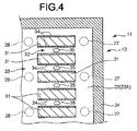
Fig. 4 is a cross-sectional view of the inkjet head shown inFig. 2 taken along a line F4-F4; -
Fig. 5 is a plane view of a nozzle plate of the inkjet head shown inFig. 1 viewed from a first surface; -
Fig. 6 is a cross-sectional view of the nozzle plate shown inFig. 5 taken along a line F6-F6; -
Fig. 7 is a plane view of the nozzle plate shown inFig. 5 viewed from a second surface; -
Fig. 8 is a cross-sectional view of a nozzle plate of an inkjet head with a general structure taken along the thickness direction; -
Fig. 9 is a cross-sectional view of the nozzle plate of the inkjet head shown inFig. 1 taken along the thickness direction; -
Fig. 10 is a plane view of a nozzle plate of an inkjet head according to a second embodiment viewed from a first surface; -
Fig. 11 is a cross-sectional view of the nozzle plate shown inFig. 10 taken along a line F11-F11; -
Fig. 12 is a plane view of the nozzle plate shown inFig. 10 viewed from a second surface; -
Fig. 13 is a plane view of a nozzle plate of an inkjet head according to a third embodiment viewed from a first surface; -
Fig. 14 is a cross-sectional view of the nozzle plate shown inFig. 13 taken along a line F14-F14; and -
Fig. 15 is a plane view of the nozzle plate shown inFig. 13 viewed from a second surface. - In accordance with one embodiment, an inkjet head comprises a pressure chamber; a nozzle plate configured to include a first surface at the side of the pressure chamber, a second surface opposite to the first surface, a first nozzle formed into a frustum which penetrates the first surface and the second surface and the diameter of which decreases as it goes closer to the second surface, and a second nozzle formed into a frustum which penetrates the first surface and the second surface and the diameter of which decreases as it goes closer to the second surface; and a driving element configured adjacent to the pressure chamber to eject droplets from the first nozzle and the second nozzle simultaneously; wherein the part of the first nozzle on the first surface is integrally connected to the part of the second nozzle on the first surface, and the part of the first nozzle on the second surface is separated from the part of the second nozzle on the second surface.
- Hereinafter, a first embodiment of the inkjet head is described with reference to
Fig. 1-Fig. 9 . The inkjet head, arranged in a printing apparatus, can print characters, images and the like on a print target such as paper with liquid (ink) supplied from the printing apparatus. The liquid (ink) used in the inkjet head further contains functional ink having various functions used for a purpose other than forming an image, in addition to various kinds of ink used to form an image. - An
inkjet head 11, arranged in an inkjet printer (printing apparatus), is connected with a tank (ink tank, liquid tank) arranged inside the inkjet printer through a tube and the like. Theinkjet head 11 includes a headmain body 12, aunit part 13 and a pair ofcircuit substrates 14. - The
unit part 13 includes a manifold which forms one part of a path between the headmain body 12 and the tank, and a member for connecting with the inkjet printer. The pair ofcircuit substrates 14 is arranged on the headmain body 12, respectively. - As shown in
Fig. 1 , the pair ofcircuit substrates 14 includes a substratemain body 15 and a pair of film carrier packages (FCP 16), respectively. The substratemain body 15 is a rectangular printed wiring board. Various electronic components and connectors are arranged in the substratemain body 15. Further, the pair ofFCPs 16 is mounted to the substratemain body 15, respectively. - The pair of FCPs 16 includes a flexible resin-made film in which a plurality of wiring is formed and
ICs 17 connected with the plurality of wiring, respectively. The film is tape automated bonding (TAB). TheIC 17 is a component for applying voltage to an electrode. The IC 17 is fixed onto the film through resin. - As shown in
Fig. 2 , the end of theFCP 16 is connected with awiring pattern 21 on a baseplate through thermocompression bonding with an anisotropic conductive film (ACF). The plurality of wiring of the FCP is electrically connected with thewiring pattern 21 through the ACF. - The head
main body 12 is a device for ejecting droplets (ink drops) to the print target. The headmain body 12 is mounted onto theunit part 13. As shown inFig. 2 , the headmain body 12 includes abaseplate 22, anozzle plate 23, aframe member 24, andblocks 25 on which a plurality ofdriving elements 31 are arranged. - As shown in
Fig. 2 andFig. 3 , thebaseplate 22 is, for example, a rectangular plate formed with ceramic such as alumina and the like. A plurality ofsupply holes 26 and a plurality ofdischarge holes 27 are arranged to penetrate thebaseplate 22. - The
supply holes 26 are arrayed at substantially central portion of thebaseplate 22 in the longitudinal direction of thebaseplate 22. Thesupply hole 26 is connected with anink supply section 28 of the manifold of theunit part 13. Thesupply hole 26 is connected with the tank through theink supply section 28. - The
discharge holes 27 are arrayed at two sides of thebaseplate 22 in the longitudinal direction with thesupply holes 26 nipped therebetween. Thedischarge hole 27 is connected with anink discharge section 29 of the manifold of theunit part 13. Thedischarge hole 27 is connected with the tank through theink discharge section 29. - The
frame member 24 is a rectangular frame formed by, for example, a nickel alloy and the like. Theframe member 24 is arranged between thebaseplate 22 and thenozzle plate 23. Theframe member 24 is adhered to a mounting surface of thebaseplate 22 and thenozzle plate 23, respectively. - The driving elements 31 (the
blocks 25 on which a plurality of driving elements are arranged) are formed by two plate-shaped piezoelectric bodies which are formed by, for example, lead zirconate titanate (PZT). The two piezoelectric bodies are bonded together in such a manner that the directions of polarization thereof are opposite in the thickness direction. - The
block 25 on which the plurality ofdriving elements 31 are arranged is adhered to the mounting surface of thebaseplate 22. As shown inFig. 2 , theblock 25 is formed in a shape of which the cross-section is trapezoidal. The top of thedriving element 31 is adhered to thenozzle plate 23. - As shown in
Fig. 3 , a plurality of grooves is formed on theblock 25. The grooves extend in a direction crossing the longitudinal direction (longitudinal direction of the inkjet head 11) of theblock 25, respectively. The plate-shaped driving elements 31 are separated from each other by the grooves. The areas in the grooves serve aspressure chambers 32 which face later describedfirst nozzles 36 andsecond nozzles 37. The drivingelements 31 can eject droplets from the later describedfirst nozzle 36 and thesecond nozzle 37 simultaneously. As shown inFig. 2 , thenozzle plate 23, the parts of thebaseplate 22 nearby the supply holes 26 and the slope part of theblock 25 constitute acommon liquid chamber 33 for supplying liquid (ink) to eachpressure chamber 32. Thecommon liquid chamber 33 is connected to eachpressure chamber 32. - As shown in
Fig. 4 ,electrodes 34 are arranged at both sides of the drivingelement 31. Theelectrodes 34 cover the bottom of the grooves (pressure chambers 32) and the lateral sides of the drivingelements 31. Theelectrodes 34 are formed by, for example, laser patterning a nickel thin film. - As shown in
Fig. 3 , a plurality ofwiring patterns 21 is arranged on the mounting surface of thebaseplate 22 to extend in a direction crossing the longitudinal direction of thebaseplate 22 from the plurality of drivingelements 31. Thewiring pattern 21 is formed by, for example, laser patterning the nickel thin film formed on thebaseplate 22. - As shown in
Fig. 3 , thenozzle plate 23, which is in a substantially rectangular shape, is formed by, for example, a polyimide film. Thenozzle plate 23 faces thebaseplate 22. Thenozzle plate 23 includes afirst surface 23A facing thepressure chambers 32 and asecond surface 23B opposite to thefirst surface 23A. - As shown in
Fig. 3 , a plurality ofintegrated nozzles 35 penetrating thenozzle plate 23 is arranged on thenozzle plate 23. The plurality ofintegrated nozzles 35 is arrayed along the longitudinal direction of thenozzle plate 23. - As shown in
Fig. 3 andFig. 5 , eachintegrated nozzle 35 includes thefirst nozzle 36 and thesecond nozzle 37. For example, thesecond nozzle 37 is arranged nearby thefirst nozzle 36 in a manner of being adjacent to thefirst nozzle 36 in a direction crossing the longitudinal direction of thenozzle plate 23. Thefirst nozzle 36 and thesecond nozzle 37 are arranged to face the same pressure chamber 32 (refer toFig. 2 ). - As shown in
Fig. 6 , the shapes of thefirst nozzle 36 and thesecond nozzle 37 are almost the same. Thefirst nozzle 36 and thesecond nozzle 37 are formed into, for example, a frustum of which the diameter decreases as it goes closer to thesecond surface 23B, and thefirst nozzle 36 and thesecond nozzle 37 penetrate thefirst surface 23A and thesecond surface 23B. Thefirst nozzle 36 includes afirst opening section 36A arranged on thefirst surface 23A and asecond opening section 36B arranged on thesecond surface 23B. Thesecond nozzle 37 includes athird opening section 37A arranged on thefirst surface 23A and afourth opening section 37B arranged on thesecond surface 23B. - As shown in
Fig. 5 , part of thefirst opening section 36A is arranged to be overlapped with part of thethird opening section 37A. That is, thefirst opening section 36A is arranged to be connected to thethird opening section 37A. Thus, as shown inFig. 6 , the part of thefirst nozzle 36 on thefirst surface 23A is integrally connected to the part of thesecond nozzle 37 on thefirst surface 23A, and these parts constitute a sharing part. - As shown in
Fig. 7 , thesecond opening section 36B, though separated from thefourth opening section 37B, is arranged nearby thefourth opening section 37B. Thus, the part of thefirst nozzle 36 on thesecond surface 23B is separated from the part of thesecond nozzle 37 on thesecond surface 23B. - As shown in
Fig. 6 , a firstperipheral surface 36C (inner peripheral surface, lateral surface and slope) of thefirst nozzle 36 extends linearly from thesecond surface 23B towards thefirst surface 23A. The firstperipheral surface 36C (inner peripheral surface, lateral surface and slope) of thefirst nozzle 36 intersects, at the way from thesecond surface 23B towards thefirst surface 23A, with a secondperipheral surface 37C (inner peripheral surface, lateral surface and slope) of thesecond nozzle 37 which extends linearly from thesecond surface 23B towards thefirst surface 23A. - Next, the manufacturing process of the
inkjet head 11 having the constitution described above is described. - First, the supply holes 26 and the discharge holes 27 are formed on the
baseplate 22 constituted by an unfired ceramic sheet (ceramic green sheet) through press molding processing. Then thebaseplate 22 is fired. - After the firing process is completed, as shown in
Fig. 3 , a pair ofblocks 25 of piezoelectric bodies serving as the driving elements is adhered to the mounting surface of thebaseplate 22. At this time, the pair ofblocks 25 is positioned against thebaseplate 22 through a jig and adhered to thebaseplate 22. - Next, a so-called tapering processing (chamfering processing) is carried out at the corners of each
block 25 adhered to thebaseplate 22. In this way, the cross-section of eachblock 25 is in a trapezoidal shape as shown inFig. 2 . Then a plurality of grooves (pressure chambers 32) and the plate-shapeddriving elements 31 are formed on theblocks 25. The plurality of grooves is formed by, for example, a multi-cutter of a dicing saw used for cutting an IC wafer and the like. - Next, the nickel thin film is formed through, for example, electroless plating on the mounting surface of the
baseplate 22, the bottoms of the grooves (pressure chambers 32) and the lateral sides of the plate-shapeddriving elements 31. Theelectrodes 34 and thewiring patterns 21 are formed by patterning the nickel thin film through laser irradiation. Further, theframe member 24 is adhered to thebaseplate 22 and then thenozzle plate 23 is adhered to theframe member 24. Then the integrated nozzles 35 (first nozzles 36 and second nozzles 37) are formed by irradiating thenozzle plate 23 with laser. In addition, it is exemplified in the present embodiment that theintegrated nozzles 35 are formed on thenozzle plate 23 through laser after thenozzle plate 23 is adhered to theframe member 24; however, the nozzle forming method is not limited to this. It is also applicable that theintegrated nozzles 35 are formed on thenozzle plate 23 through pressing process and the like in advance, and then thenozzle plate 23 is adhered to theframe member 24. - At last, the pair of
circuit substrates 14 is adhered to thebaseplate 22 through an ACF, and in this way, theinkjet head 11 is completed. - Next, the liquid ejecting operation of the
inkjet head 11 according to the present embodiment is described. Theinkjet head 11 according to the present embodiment is a liquid (ink) circulationtype inkjet head 11, and the ink ejected from the tank is supplied to thepressure chamber 32 through the supply holes 26 and thecommon liquid chamber 33. The ink that is not ejected and used in thepressure chamber 32 is collected to the tank from the discharge holes 27. In this way, in theinkjet head 11 according to the present embodiment, the ink is circulated between the tank and theinkjet head 11. - Herein, the liquid (ink) ejecting operation is described on the basis of the comparison with an inkjet head 41 (as shown in
Fig. 8 ) in which thefirst nozzle 36 and thesecond nozzle 37 are independent and thepressure chamber 32 connected with these nozzles is also independent. - As shown in
Fig. 8 , in theconventional inkjet head 41, the drivingelements 31 are operated to increase or decrease the volume of thepressure chamber 32 when to eject liquid from thenozzle 42. For example, if the volume of thepressure chamber 32 is decreased to a volume smaller than the original volume after being increased temporarily, the liquid in thepressure chamber 32 is pressurized, and droplets are ejected vigorously towards the print target from thenozzles 42. Themeniscus surface 43 protrudes outwards immediately before the liquid is ejected and is ejected to the print target as droplets as it is. After the droplets are ejected, themeniscus surface 43 is retracted backwards into thenozzle 42. As stated above, themeniscus surface 43 vibrates in a direction indicated by an arrow under the pressure of the drivingelement 31 immediately before and after the printing. As a result, the liquid (ink) in thepressure chamber 32 also vibrates in the direction indicated by the arrow. At this time, as thefirst nozzle 36 and thepressure chamber 32 connected thereto are independent from thesecond nozzle 37 and thepressure chamber 32 connected thereto, thus, the vibration of the liquid inside thepressure chambers 32 is independent. Thus, difference occurs in the vibration of the liquid (meniscus surface 43) due to the size variation of thefirst nozzles 36 and thesecond nozzles 37 and the volume variation of thepressure chambers 32. As a result, a variation in the ejecting performance such as the liquid ejecting speed, liquid ejecting amount and the like is likely to occur between thefirst nozzle 36 and thesecond nozzle 37. -
Fig. 9 is an enlarged diagram illustrating the parts surrounding thefirst nozzle 36 and thesecond nozzle 37 of theinkjet head 11 according to the present embodiment. - In the
inkjet head 11, the drivingelements 31 are driven to increase or decrease the volume of thepressure chamber 32 when to eject liquid from theintegrated nozzles 35, similar to that shown inFig. 8 . For example, if the volume of thepressure chamber 32 is decreased to a volume smaller than the original volume after being increased temporarily, the liquid in thepressure chamber 32 is pressurized, and droplets are ejected simultaneously from thefirst nozzle 36 and thesecond nozzle 37. The meniscus surfaces 43 of thefirst nozzle 36 and thesecond nozzle 37 protrude outwards immediately before the liquid is ejected and are ejected to the print target as droplets as it is. After the droplets are ejected, themeniscus surface 43 of thefirst nozzle 36 and themeniscus surface 43 of thesecond nozzle 37 are retracted backwards into thefirst nozzle 36 and thesecond nozzle 37. As stated above, themeniscus surface 43 vibrates in a direction indicated by an arrow under the pressure of the drivingelement 31 immediately before and after the printing. As a result, the liquid in the parts of thefirst nozzle 36 and thesecond nozzle 37 nearby the pressure chambers 32 (thefirst surface 23A side of the nozzle plate 23) and the liquid (ink) in thepressure chamber 32 also vibrate in the direction indicated by the arrow. - In the present embodiment, as the
first nozzle 36, thesecond nozzle 37 and thepressure chambers 32 connected thereto are connected to each other, thus, the vibration of the liquid in these components are synchronous. As a result, it is possible to prevent the occurrence of difference in the vibration of the liquid (the vibration of the meniscus surfaces 43) caused by the size variation of thefirst nozzle 36 and thesecond nozzle 37. As a result, it is possible to prevent the occurrence of a variation in the ejecting performance such as the liquid ejecting speed, liquid ejecting amount and the like between thefirst nozzle 36 and thesecond nozzle 37. - In accordance with the first embodiment, the
inkjet head 11 comprises thepressure chamber 32; thenozzle plate 23 including thefirst surface 23A at the side of thepressure chamber 32, thesecond surface 23B opposite to thefirst surface 23A, thefirst nozzle 36 formed into a frustum which penetrates thefirst surface 23A and thesecond surface 23B and the diameter of which decreases as it goes closer to thesecond surface 23B, and thesecond nozzle 37 formed into a frustum which penetrates thefirst surface 23A and thesecond surface 23B and the diameter of which decreases as it goes closer to thesecond surface 23B; and the drivingelement 31 which is arranged adjacent to thepressure chamber 32 to eject droplets from thefirst nozzle 36 and thesecond nozzle 37 simultaneously; wherein the part of thefirst nozzle 36 on thefirst surface 23A is integrally connected to the part of thesecond nozzle 37 on thefirst surface 23A, and the part of thefirst nozzle 36 on thesecond surface 23B is separated from the part of thesecond nozzle 37 on thesecond surface 23B. - In accordance with the constitution, the droplets can be ejected from the
first nozzle 36 and thesecond nozzle 37 simultaneously, thus, there can be provided aninkjet head 11 that is capable of ejecting a large amount of droplets through one ejecting driving operation. Further, in accordance with the constitution, the part of thefirst nozzle 36 on thefirst surface 23A can be integrally connected to the part of thesecond nozzle 37 on thefirst surface 23A. In this way, it is possible to synchronize (share) the vibration of themeniscus surface 43 of thefirst nozzle 36 and thesecond nozzle 37, which can reduce the variation in the liquid ejecting performance caused by the size variation of thefirst nozzles 36 and thesecond nozzles 37. - The peripheral surface of the
first nozzle 36 extends linearly from thesecond surface 23B towards thefirst surface 23A and intersects, at the way from thesecond surface 23B towards thefirst surface 23A, with the peripheral surface of thesecond nozzle 37 which extends linearly from thesecond surface 23B towards thefirst surface 23A. In accordance with the constitution, a part connected with thesecond nozzle 37 can be arranged at the peripheral surface of thefirst nozzle 36 at the way from thesecond surface 23B towards thefirst surface 23A. In this way, it is possible to arrange the part of thefirst nozzle 36 on thesecond surface 23B more closer to the part of thesecond nozzle 37 on thesecond surface 23B, which can make the synchronization of the vibration of themeniscus surface 43 between the two nozzles much more easier. Thus, it is possible to prevent the occurrence of the variation in the liquid ejecting performance caused by the size variation of thefirst nozzles 36 and thesecond nozzles 37. - Hereinafter, the second embodiment of the
inkjet head 11 is described with reference toFig. 10-Fig. 12 . Theinkjet head 11 described in the present embodiment is the same as that described in the first embodiment except that a sharing part of the first nozzle 36-thefourth nozzle 52 is formed. Thus, the different part is mainly described and the same part is not shown or described repeatedly. -
Fig. 10 is a diagram of thenozzle plate 23 viewed from the pressure chamber 32 (first surface 23A).Fig. 11 is a cross-sectional view taken along a line F11-F11 shown inFig. 10 .Fig. 12 is a diagram of thenozzle plate 23 viewed from an outer side (second surface side). - A plurality of
integrated nozzles 35 that penetrates thenozzle plate 23 is arranged on thenozzle plate 23. Similar to those shown inFig. 1 , the plurality ofintegrated nozzles 35 is arranged along the longitudinal direction of thenozzle plate 23. - As shown in
Fig. 10 , eachintegrated nozzle 35 includes thefirst nozzle 36, thesecond nozzle 37, athird nozzle 51 and afourth nozzle 52. Thesecond nozzle 37 is arranged nearby thefirst nozzle 36 and is adjacent to thefirst nozzle 36 in, for example, a direction crossing the longitudinal direction of thenozzle plate 23. Thethird nozzle 51 is arranged nearby thefirst nozzle 36 and is adjacent to thefirst nozzle 36 in, for example, the longitudinal direction of thenozzle plate 23. Thefourth nozzle 52 is arranged nearby thesecond nozzle 37 and is adjacent to thesecond nozzle 37 in, for example, the longitudinal direction of thenozzle plate 23. As shown inFig. 12 , thefirst nozzle 36 is in diagonal to thefourth nozzle 52, and thesecond nozzle 37 is in diagonal to thethird nozzle 51. The first nozzle 36-fourth nozzle 52 are arranged to face thesame pressure chamber 32. - As shown in
Fig. 11 , the shapes of the first nozzle 36-fourth nozzle 52 are almost the same. The first nozzle 36-fourth nozzle 52 are formed into a frustum which penetrates thefirst surface 23A and thesecond surface 23B and the diameter of which decreases as it goes closer to thesecond surface 23B. Thefirst nozzle 36 includes thefirst opening section 36A arranged on thefirst surface 23A and thesecond opening section 36B arranged on thesecond surface 23B. Thesecond nozzle 37 includes thethird opening section 37A arranged on thefirst surface 23A and thefourth opening section 37B arranged on thesecond surface 23B. - As shown in
Fig. 10 andFig. 12 , thethird nozzle 51 includes afifth opening section 51A arranged on thefirst surface 23A and asixth opening section 51B arranged on thesecond surface 23B. Thefourth nozzle 52 includes aseventh opening section 52A arranged on thefirst surface 23A and aneighth opening section 52B arranged on thesecond surface 23B. - As shown in
Fig. 10 , part of thefirst opening section 36A is arranged in a manner of being overlapped with part of thethird opening section 37A and thefifth opening section 51A. Thus, thefirst opening section 36A is connected to thethird opening section 37A and thefifth opening section 51A. Similarly, part of theseventh opening section 52A is arranged in a manner of being overlapped with part of thethird opening section 37A and thefifth opening section 51A. Thus, theseventh opening section 52A is connected to thethird opening section 37A and thefifth opening section 51A. - Thus, in the present embodiment, the parts of the first nozzle 36-
fourth nozzle 52 on thefirst surface 23A constitute the sharing part, that is, are integrally arranged. - As shown in
Fig. 12 , thesecond opening section 36B, though separated from thefourth opening section 37B and thesixth opening section 51B, is arranged nearby thefourth opening section 37B and thesixth opening section 51B. Similarly, theeighth opening section 52B, though separated from thefourth opening section 37B and thesixth opening section 51B, is arranged nearby thefourth opening section 37B and thesixth opening section 51B. Thus, the parts of the first nozzle 36-fourth nozzle 52 on thesecond surface 23B are separated from each other to constitute independent parts. - As shown in
Fig. 11 , the firstperipheral surface 36C (inner peripheral surface, lateral surface and slope) of thefirst nozzle 36 extends linearly from thesecond surface 23B towards thefirst surface 23A. The firstperipheral surface 36C of thefirst nozzle 36 intersects, at the way from thesecond surface 23B towards thefirst surface 23A, with the secondperipheral surface 37C (inner peripheral surface, lateral surface and slope) of thesecond nozzle 37 which extends linearly from thesecond surface 23B towards thefirst surface 23A. Similarly, as shown inFig. 10 andFig. 12 , the firstperipheral surface 36C (inner peripheral surface, lateral surface and slope) of thefirst nozzle 36 intersects, at the way from thesecond surface 23B towards thefirst surface 23A, with a thirdperipheral surface 51C (inner peripheral surface, lateral surface and slope) of thethird nozzle 51 which extends linearly from thesecond surface 23B towards thefirst surface 23A. - Further, a fourth
peripheral surface 52C (inner peripheral surface, lateral surface and slope) of thefourth nozzle 52 extends linearly from thesecond surface 23B towards thefirst surface 23A. The fourthperipheral surface 52C of thefourth nozzle 52 intersects, at the way from thesecond surface 23B towards thefirst surface 23A, with the secondperipheral surface 37C of thesecond nozzle 37 and the thirdperipheral surface 51C of thethird nozzle 51. - In the present embodiment, a pair of driving
elements 31 between which thepressure chamber 32 is nipped can eject droplets from thefirst nozzle 36, thesecond nozzle 37, thethird nozzle 51 and thefourth nozzle 52 simultaneously. - The manufacturing process of the
inkjet head 11 according to the present embodiment is almost the same as that described in the first embodiment except that the number of the nozzles formed as theintegrated nozzle 35 is different from that in the first embodiment. - In the present embodiment, the number of the nozzles included in the
integrated nozzle 35 is different from that in the first embodiment, thus, the amount of the droplets (ink drops) that can be ejected by theinkjet head 11 according to the present embodiment through one ejecting driving operation is different from that of theinkjet head 11 described in the first embodiment. That is, theinkjet head 11 according to the present embodiment can eject twice as much droplets (ink drops) as theinkjet head 11 in the first embodiment. The other parts of the present embodiment have the same functions as those of the first embodiment. - In accordance with the present embodiment, the inkjet head 11 includes the pressure chamber 32; the nozzle plate 23 including the first surface 23A at the side of the pressure chamber 32, the second surface 23B opposite to the first surface 23A, the first nozzle 36 formed into a frustum which penetrates the first surface 23A and the second surface 23B and the diameter of which decreases as it goes closer to the second surface 23B, the second nozzle 37 formed into a frustum which penetrates the first surface 23A and the second surface 23B and the diameter of which decreases as it goes closer to the second surface 23B, the third nozzle 51 formed into a frustum which penetrates the first surface 23A and the second surface 23B and the diameter of which decreases as it goes closer to the second surface 23B, and the fourth nozzle 52 formed into a frustum which penetrates the first surface 23A and the second surface 23B and the diameter of which decreases as it goes closer to the second surface 23B; and the driving element 31 which is arranged adjacent to the pressure chamber 32 to eject droplets from the first nozzle 36, the second nozzle 37, the third nozzle 51 and the fourth nozzle 52 simultaneously; wherein the parts of the first nozzle 36-fourth nozzle 52 on the first surface 23A are integrally connected to each other, and the parts of the first nozzle 36-fourth nozzle 52 on the second surface 23B are separated from each other.
- In accordance with the constitution, the droplets can be ejected from the first nozzle 36-
fourth nozzle 52 simultaneously, thus, there can be provided aninkjet head 11 that is capable of ejecting a large amount of droplets through one ejecting driving operation. Further, in accordance with the constitution, there can be provided aninkjet head 11 in which the ejecting performance of the first nozzle 36-fourth nozzle 52 is uniform. - Hereinafter, the third embodiment of the
inkjet head 11 is described with reference toFig. 13-Fig. 15 . Though theinkjet head 11 according to the present embodiment is the same as that described in the second embodiment in the point that the sharing part is formed at a certain position at thefirst surface 23A of the first nozzle 36-fourth nozzle 52, the shape of the sharing part is different from that in the second embodiment. However, other parts of the third embodiment are the same as those of the second embodiment. Thus, the different part is mainly described and the same part is not shown or described repeatedly. -
Fig. 13 is a diagram of thenozzle plate 23 viewed from the pressure chamber 32 (first surface 23A).Fig. 14 is a cross-sectional view taken along a line F14-F14 shown inFig. 13 .Fig. 15 is a diagram of thenozzle plate 23 viewed from an outer side (second surface side). - A plurality of
integrated nozzles 35 that penetrates thenozzle plate 23 is arranged on thenozzle plate 23. Similar to those shown inFig. 1 , the plurality ofintegrated nozzles 35 is arranged along the longitudinal direction of thenozzle plate 23 at specific intervals. Eachintegrated nozzle 35 includes thefirst nozzle 36, thesecond nozzle 37, athird nozzle 51 and afourth nozzle 52. Thesecond nozzle 37 is arranged nearby thefirst nozzle 36 and is adjacent to thefirst nozzle 36 in, for example, a direction crossing the longitudinal direction of thenozzle plate 23. Thethird nozzle 51 is arranged nearby thefirst nozzle 36 and is adjacent to thefirst nozzle 36 in, for example, the longitudinal direction of thenozzle plate 23. Thefourth nozzle 52 is arranged nearby thesecond nozzle 37 and is adjacent to thesecond nozzle 37 in, for example, the longitudinal direction of thenozzle plate 23. As shown inFig. 15 , thefirst nozzle 36 is in diagonal to thefourth nozzle 52, and thesecond nozzle 37 is in diagonal to thethird nozzle 51. The first nozzle 36-fourth nozzle 52 are arranged to face thesame pressure chamber 32. - The shapes of the first nozzle 36-
fourth nozzle 52 are almost the same. That is, each of the first nozzle 36-fourth nozzle 52 is formed into, for example, a frustum. Thefirst nozzle 36 includes thefirst opening section 36A arranged on thefirst surface 23A and thesecond opening section 36B arranged on thesecond surface 23B. Thesecond nozzle 37 includes thethird opening section 37A arranged on thefirst surface 23A and thefourth opening section 37B arranged on thesecond surface 23B. Thethird nozzle 51 includes thefifth opening section 51A arranged on thefirst surface 23A and thesixth opening section 51B arranged on thesecond surface 23B. Thefourth nozzle 52 includes theseventh opening section 52A arranged on thefirst surface 23A and theeighth opening section 52B arranged on thesecond surface 23B. - In the present embodiment, the
first opening section 36A-seventh opening section 52A constitute an integrated substantially-square sharing opening section. Thus, in the present embodiment, the parts of the first nozzle 36-fourth nozzle 52 on thefirst surface 23A constitute a substantially quadrangular sharing part, that is, are integrally arranged. - As shown in
Fig. 15 , thesecond opening section 36B, though separated from thefourth opening section 37B and thesixth opening section 51B, is arranged nearby thefourth opening section 37B and thesixth opening section 51B. Similarly, theeighth opening section 52B, though separated from thefourth opening section 37B and thesixth opening section 51B, is arranged nearby thefourth opening section 37B and thesixth opening section 51B. Thus, the parts of the first nozzle 36-fourth nozzle 52 on thesecond surface 23B are separated from each other to constitute independent parts. - As shown in
Fig. 14 , the firstperipheral surface 36C (inner peripheral surface, lateral surface and slope) of thefirst nozzle 36 extends linearly from thesecond surface 23B towards thefirst surface 23A. The firstperipheral surface 36C of thefirst nozzle 36 intersects, at the way from thesecond surface 23B towards thefirst surface 23A, with the secondperipheral surface 37C (inner peripheral surface, lateral surface and slope) of thesecond nozzle 37 which extends linearly from thesecond surface 23B towards thefirst surface 23A. Similarly, as shown inFig. 13 andFig. 15 , the firstperipheral surface 36C (inner peripheral surface, lateral surface and slope) of thefirst nozzle 36 intersects, at the way from thesecond surface 23B towards thefirst surface 23A, with a thirdperipheral surface 51C (inner peripheral surface, lateral surface and slope) of thethird nozzle 51 which extends linearly from thesecond surface 23B towards thefirst surface 23A. - Further, the fourth
peripheral surface 52C (inner peripheral surface, lateral surface and slope) of thefourth nozzle 52 extends linearly from thesecond surface 23B towards thefirst surface 23A. The fourthperipheral surface 52C of thefourth nozzle 52 intersects, at the way from thesecond surface 23B towards thefirst surface 23A, with the secondperipheral surface 37C of thesecond nozzle 37 and the thirdperipheral surface 51C of thethird nozzle 51. - In the present embodiment, a pair of driving
elements 31 between which thepressure chamber 32 is nipped can eject droplets from thefirst nozzle 36, thesecond nozzle 37, thethird nozzle 51 and thefourth nozzle 52 simultaneously. - The manufacturing process of the
inkjet head 11 according to the present embodiment is almost the same as that described in the second embodiment. In the present embodiment, in the forming process of theintegrated nozzle 35, the parts of the first nozzle 36-fourth nozzle 52 on thefirst surface 23A are formed as a substantially-square sharing opening section. Theintegrated nozzle 35 may be formed through laser processing or pressing processing. In the present embodiment, theinkjet head 11 has almost the same functions as those in the second embodiment. - In accordance with the present embodiment, the droplets can be ejected from the first nozzle 36-
fourth nozzle 52 simultaneously, thus, there can be provided aninkjet head 11 that is capable of ejecting a large amount of droplets through one ejecting driving operation. Further, in accordance with the constitution, there can be provided aninkjet head 11 in which the ejecting performance of the first nozzle 36-fourth nozzle 52 is uniform. - The first-third embodiments are described above, however, the components in these embodiments may be appropriately combined.
- While certain embodiments have been described, these embodiments have been presented by way of example only, and are not intended to limit the scope of the invention. Indeed, the novel embodiments described herein may be embodied in a variety of other forms; furthermore, various omissions, substitutions and changes in the form of the embodiments described herein may be made without departing from the spirit of the invention. The accompanying claims and their equivalents are intended to cover such forms or modifications as would fall within the scope and spirit of the invention.
Claims (4)
- An inkjet head comprising:a pressure chamber;a nozzle plate configured to include a first surface at the side of the pressure chamber, a second surface opposite to the first surface, a first nozzle formed into a frustum which penetrates the first surface and the second surface and the diameter of which decreases as it goes closer to the second surface, and a second nozzle formed into a frustum which penetrates the first surface and the second surface and the diameter of which decreases as it goes closer to the second surface; anda driving element configured adjacent to the pressure chamber to eject droplets from the first nozzle and the second nozzle simultaneously; whereinthe part of the first nozzle on the first surface is integrally connected to the part of the second nozzle on the first surface, andthe part of the first nozzle on the second surface is separated from the part of the second nozzle on the second surface.
- The inkjet head according to claim 1, wherein
the peripheral surface of the first nozzle extends linearly from the second surface towards the first surface and intersects, at the way from the second surface towards the first surface, with the peripheral surface of the second nozzle which extends linearly from the second surface towards the first surface. - An inkjet head comprising:a pressure chamber;a nozzle plate configured to include a first surface at the side of the pressure chamber, a second surface opposite to the first surface, a first nozzle formed into a frustum which penetrates the first surface and the second surface and the diameter of which decreases as it goes closer to the second surface, a second nozzle formed into a frustum which penetrates the first surface and the second surface and the diameter of which decreases as it goes closer to the second surface, a third nozzle formed into a frustum which penetrates the first surface and the second surface and the diameter of which decreases as it goes closer to the second surface, and a fourth nozzle formed into a frustum which penetrates the first surface and the second surface and the diameter of which decreases as it goes closer to the second surface; anda driving element configured adjacent to the pressure chamber to eject droplets from the first nozzle, the second nozzle, the third nozzle and the fourth nozzle simultaneously; whereinthe parts of the first-fourth nozzles on the first surface are integrally connected to each other, andthe parts of the first-fourth nozzles on the second surface are separated from each other.
- The inkjet head according to claim 3, wherein
the parts of the first-fourth nozzles on the first surface are integrally arranged into a substantially quadrangular shape.
Applications Claiming Priority (1)
| Application Number | Priority Date | Filing Date | Title |
|---|---|---|---|
| JP2013242094A JP6216626B2 (en) | 2013-11-22 | 2013-11-22 | Inkjet head |
Publications (2)
| Publication Number | Publication Date |
|---|---|
| EP2875955A1 true EP2875955A1 (en) | 2015-05-27 |
| EP2875955B1 EP2875955B1 (en) | 2019-10-09 |
Family
ID=52013827
Family Applications (1)
| Application Number | Title | Priority Date | Filing Date |
|---|---|---|---|
| EP14194329.0A Active EP2875955B1 (en) | 2013-11-22 | 2014-11-21 | Inkjet head |
Country Status (4)
| Country | Link |
|---|---|
| US (2) | US9446591B2 (en) |
| EP (1) | EP2875955B1 (en) |
| JP (1) | JP6216626B2 (en) |
| CN (2) | CN104647901B (en) |
Cited By (1)
| Publication number | Priority date | Publication date | Assignee | Title |
|---|---|---|---|---|
| EP3162566A1 (en) * | 2015-10-27 | 2017-05-03 | Toshiba TEC Kabushiki Kaisha | Inkjet head and inkjet printer |
Families Citing this family (7)
| Publication number | Priority date | Publication date | Assignee | Title |
|---|---|---|---|---|
| JP2015199289A (en) | 2014-04-09 | 2015-11-12 | 株式会社東芝 | liquid discharge head |
| JP6302401B2 (en) | 2014-12-04 | 2018-03-28 | 株式会社東芝 | Inkjet head and printer |
| JP7030415B2 (en) | 2017-03-09 | 2022-03-07 | 東芝テック株式会社 | Liquid discharge head and liquid discharge device |
| JP7146521B2 (en) * | 2018-08-09 | 2022-10-04 | 東芝テック株式会社 | Inkjet head, inkjet device, and method for manufacturing inkjet head |
| JP7110126B2 (en) * | 2019-01-10 | 2022-08-01 | 東芝テック株式会社 | Inkjet head, inkjet device, and method for manufacturing inkjet head |
| US11642886B2 (en) | 2021-04-08 | 2023-05-09 | Funai Electric Co., Ltd. | Modified fluid jet plume characteristics |
| US11642887B2 (en) | 2021-04-22 | 2023-05-09 | Funai Electric Co., Ltd. | Ejection head having optimized fluid ejection characteristics |
Citations (4)
| Publication number | Priority date | Publication date | Assignee | Title |
|---|---|---|---|---|
| JP2002154199A (en) * | 2000-11-20 | 2002-05-28 | Konica Corp | Ink-jet image forming method and ink-jet image recording apparatus |
| JP2003080700A (en) * | 2001-09-12 | 2003-03-19 | Olympus Optical Co Ltd | Ink head |
| JP2009226814A (en) * | 2008-03-24 | 2009-10-08 | Seiko Epson Corp | Liquid injection head, nozzle plate for liquid injection head, punch and manufacturing method of metal plate material |
| JP2009233879A (en) * | 2008-03-26 | 2009-10-15 | Seiko Epson Corp | Liquid jet head, method for manufacturing liquid jet head and method for manufacturing metal sheet |
Family Cites Families (13)
| Publication number | Priority date | Publication date | Assignee | Title |
|---|---|---|---|---|
| JPH0647914A (en) | 1992-03-06 | 1994-02-22 | Seikosha Co Ltd | Ink jet head |
| JP2002151499A (en) * | 2000-11-14 | 2002-05-24 | Hitachi Kokusai Electric Inc | Semiconductor manufacturing device |
| US20020140774A1 (en) * | 2001-03-30 | 2002-10-03 | Olympus Optical Co., Ltd. | Ink head |
| JP2002331658A (en) * | 2001-05-08 | 2002-11-19 | Fuji Xerox Co Ltd | Ink jet recording head and ink jet recorder |
| US6779861B2 (en) * | 2002-12-16 | 2004-08-24 | Xerox Corporation | Enhanced dot resolution for inkjet printing |
| JP2005254579A (en) * | 2004-03-10 | 2005-09-22 | Brother Ind Ltd | Droplet jet apparatus |
| JP4701969B2 (en) * | 2005-09-29 | 2011-06-15 | ブラザー工業株式会社 | Inkjet head and inkjet recording apparatus |
| JP5222564B2 (en) | 2008-01-04 | 2013-06-26 | 理想科学工業株式会社 | Ink circulation confirmation method and ink filling method |
| JP5689652B2 (en) * | 2010-11-10 | 2015-03-25 | エスアイアイ・プリンテック株式会社 | Liquid ejecting head, liquid ejecting apparatus, and method of manufacturing liquid ejecting head |
| JP2012187717A (en) * | 2011-03-08 | 2012-10-04 | Toshiba Tec Corp | Inkjet head |
| JP2012187716A (en) * | 2011-03-08 | 2012-10-04 | Toshiba Tec Corp | Inkjet head and method for manufacturing the inkjet head |
| JP5905266B2 (en) * | 2011-06-28 | 2016-04-20 | エスアイアイ・プリンテック株式会社 | Liquid ejecting head, liquid ejecting apparatus, and method of manufacturing liquid ejecting head |
| JP2013132810A (en) * | 2011-12-26 | 2013-07-08 | Sii Printek Inc | Liquid jet head, liquid jet apparatus, and method of manufacturing liquid jet head |
-
2013
- 2013-11-22 JP JP2013242094A patent/JP6216626B2/en active Active
-
2014
- 2014-10-23 CN CN201410571983.4A patent/CN104647901B/en active Active
- 2014-10-23 CN CN201610729372.7A patent/CN106346955B/en active Active
- 2014-11-20 US US14/548,602 patent/US9446591B2/en active Active
- 2014-11-21 EP EP14194329.0A patent/EP2875955B1/en active Active
-
2016
- 2016-08-22 US US15/242,803 patent/US9969166B2/en active Active
Patent Citations (4)
| Publication number | Priority date | Publication date | Assignee | Title |
|---|---|---|---|---|
| JP2002154199A (en) * | 2000-11-20 | 2002-05-28 | Konica Corp | Ink-jet image forming method and ink-jet image recording apparatus |
| JP2003080700A (en) * | 2001-09-12 | 2003-03-19 | Olympus Optical Co Ltd | Ink head |
| JP2009226814A (en) * | 2008-03-24 | 2009-10-08 | Seiko Epson Corp | Liquid injection head, nozzle plate for liquid injection head, punch and manufacturing method of metal plate material |
| JP2009233879A (en) * | 2008-03-26 | 2009-10-15 | Seiko Epson Corp | Liquid jet head, method for manufacturing liquid jet head and method for manufacturing metal sheet |
Cited By (1)
| Publication number | Priority date | Publication date | Assignee | Title |
|---|---|---|---|---|
| EP3162566A1 (en) * | 2015-10-27 | 2017-05-03 | Toshiba TEC Kabushiki Kaisha | Inkjet head and inkjet printer |
Also Published As
| Publication number | Publication date |
|---|---|
| CN104647901B (en) | 2017-11-10 |
| JP2015100966A (en) | 2015-06-04 |
| CN106346955B (en) | 2017-11-14 |
| JP6216626B2 (en) | 2017-10-18 |
| US9969166B2 (en) | 2018-05-15 |
| CN106346955A (en) | 2017-01-25 |
| CN104647901A (en) | 2015-05-27 |
| US20150145923A1 (en) | 2015-05-28 |
| EP2875955B1 (en) | 2019-10-09 |
| US20160355016A1 (en) | 2016-12-08 |
| US9446591B2 (en) | 2016-09-20 |
Similar Documents
| Publication | Publication Date | Title |
|---|---|---|
| EP2875955B1 (en) | Inkjet head | |
| US8322823B2 (en) | Liquid ejecting head, manufacturing method thereof, and liquid ejecting apparatus | |
| CN107538914B (en) | MEMS device and method of manufacturing the same, liquid ejection head and method of manufacturing the same | |
| JP2010158864A (en) | Liquid jet head chip, method of manufacturing the same, liquid jet head, and liquid jet recording apparatus | |
| JP2007152624A (en) | Inkjet recorder, inkjet head, inkjet head chip, and method for manufacturing the same | |
| JP2011136462A (en) | Liquid droplet ejecting head and liquid droplet ejecting device | |
| US8985749B2 (en) | Liquid ejection head and liquid ejection apparatus | |
| US8308276B2 (en) | Liquid ejecting head and liquid ejecting apparatus | |
| JP2008213239A (en) | Method for manufacturing liquid jetting head unit | |
| JP2018039174A (en) | Manufacturing method for pressure generation device | |
| US8955946B2 (en) | Liquid discharge apparatus, piezoelectric actuator, and method for producing liquid discharge apparatus | |
| JP6407217B2 (en) | Inkjet head | |
| JP2013146885A (en) | Liquid ejection head, liquid ejection device, and method of manufacturing liquid ejection head | |
| US11845275B2 (en) | Liquid discharge head | |
| JP6269794B2 (en) | Droplet discharge head, printing apparatus, and method of manufacturing droplet discharge head | |
| US9064782B2 (en) | Wiring structure, droplet discharge head, and droplet discharge apparatus | |
| JP2023046800A (en) | Piezoelectric actuator and liquid discharge head | |
| JP2024027917A (en) | Liquid ejection head and liquid ejection device | |
| JP2015107579A (en) | Inkjet head and inkjet head manufacturing method | |
| JP2010182710A (en) | Piezoelectric element unit, liquid injection head and liquid injection device | |
| JP2010000746A (en) | Droplet discharge head, manufacturing method therefor, and ink jet recording device | |
| JP2006224311A (en) | Droplet delivering head and droplet delivering device | |
| JP2010240846A (en) | Method for manufacturing liquid droplet ejection head | |
| JP2004142410A (en) | Inkjet head, inkjet recorder, and housing forming method | |
| JP2010214753A (en) | Method of manufacturing liquid jetting head |
Legal Events
| Date | Code | Title | Description |
|---|---|---|---|
| PUAI | Public reference made under article 153(3) epc to a published international application that has entered the european phase |
Free format text: ORIGINAL CODE: 0009012 |
|
| 17P | Request for examination filed |
Effective date: 20141121 |
|
| AK | Designated contracting states |
Kind code of ref document: A1 Designated state(s): AL AT BE BG CH CY CZ DE DK EE ES FI FR GB GR HR HU IE IS IT LI LT LU LV MC MK MT NL NO PL PT RO RS SE SI SK SM TR |
|
| AX | Request for extension of the european patent |
Extension state: BA ME |
|
| R17P | Request for examination filed (corrected) |
Effective date: 20151117 |
|
| RBV | Designated contracting states (corrected) |
Designated state(s): AL AT BE BG CH CY CZ DE DK EE ES FI FR GB GR HR HU IE IS IT LI LT LU LV MC MK MT NL NO PL PT RO RS SE SI SK SM TR |
|
| STAA | Information on the status of an ep patent application or granted ep patent |
Free format text: STATUS: EXAMINATION IS IN PROGRESS |
|
| 17Q | First examination report despatched |
Effective date: 20180718 |
|
| GRAP | Despatch of communication of intention to grant a patent |
Free format text: ORIGINAL CODE: EPIDOSNIGR1 |
|
| STAA | Information on the status of an ep patent application or granted ep patent |
Free format text: STATUS: GRANT OF PATENT IS INTENDED |
|
| INTG | Intention to grant announced |
Effective date: 20190430 |
|
| RIN1 | Information on inventor provided before grant (corrected) |
Inventor name: SUZUKI, ISAO |
|
| GRAS | Grant fee paid |
Free format text: ORIGINAL CODE: EPIDOSNIGR3 |
|
| GRAA | (expected) grant |
Free format text: ORIGINAL CODE: 0009210 |
|
| STAA | Information on the status of an ep patent application or granted ep patent |
Free format text: STATUS: THE PATENT HAS BEEN GRANTED |
|
| RAP1 | Party data changed (applicant data changed or rights of an application transferred) |
Owner name: TOSHIBA TEC KABUSHIKI KAISHA Owner name: KABUSHIKI KAISHA TOSHIBA |
|
| AK | Designated contracting states |
Kind code of ref document: B1 Designated state(s): AL AT BE BG CH CY CZ DE DK EE ES FI FR GB GR HR HU IE IS IT LI LT LU LV MC MK MT NL NO PL PT RO RS SE SI SK SM TR |
|
| RAP1 | Party data changed (applicant data changed or rights of an application transferred) |
Owner name: KABUSHIKI KAISHA TOSHIBA Owner name: TOSHIBA TEC KABUSHIKI KAISHA |
|
| REG | Reference to a national code |
Ref country code: GB Ref legal event code: FG4D |
|
| REG | Reference to a national code |
Ref country code: CH Ref legal event code: EP |
|
| REG | Reference to a national code |
Ref country code: IE Ref legal event code: FG4D |
|
| REG | Reference to a national code |
Ref country code: DE Ref legal event code: R096 Ref document number: 602014054826 Country of ref document: DE |
|
| REG | Reference to a national code |
Ref country code: AT Ref legal event code: REF Ref document number: 1188329 Country of ref document: AT Kind code of ref document: T Effective date: 20191115 |
|
| REG | Reference to a national code |
Ref country code: NL Ref legal event code: MP Effective date: 20191009 |
|
| REG | Reference to a national code |
Ref country code: LT Ref legal event code: MG4D |
|
| REG | Reference to a national code |
Ref country code: AT Ref legal event code: MK05 Ref document number: 1188329 Country of ref document: AT Kind code of ref document: T Effective date: 20191009 |
|
| PG25 | Lapsed in a contracting state [announced via postgrant information from national office to epo] |
Ref country code: NO Free format text: LAPSE BECAUSE OF FAILURE TO SUBMIT A TRANSLATION OF THE DESCRIPTION OR TO PAY THE FEE WITHIN THE PRESCRIBED TIME-LIMIT Effective date: 20200109 Ref country code: PL Free format text: LAPSE BECAUSE OF FAILURE TO SUBMIT A TRANSLATION OF THE DESCRIPTION OR TO PAY THE FEE WITHIN THE PRESCRIBED TIME-LIMIT Effective date: 20191009 Ref country code: BG Free format text: LAPSE BECAUSE OF FAILURE TO SUBMIT A TRANSLATION OF THE DESCRIPTION OR TO PAY THE FEE WITHIN THE PRESCRIBED TIME-LIMIT Effective date: 20200109 Ref country code: FI Free format text: LAPSE BECAUSE OF FAILURE TO SUBMIT A TRANSLATION OF THE DESCRIPTION OR TO PAY THE FEE WITHIN THE PRESCRIBED TIME-LIMIT Effective date: 20191009 Ref country code: LT Free format text: LAPSE BECAUSE OF FAILURE TO SUBMIT A TRANSLATION OF THE DESCRIPTION OR TO PAY THE FEE WITHIN THE PRESCRIBED TIME-LIMIT Effective date: 20191009 Ref country code: AT Free format text: LAPSE BECAUSE OF FAILURE TO SUBMIT A TRANSLATION OF THE DESCRIPTION OR TO PAY THE FEE WITHIN THE PRESCRIBED TIME-LIMIT Effective date: 20191009 Ref country code: NL Free format text: LAPSE BECAUSE OF FAILURE TO SUBMIT A TRANSLATION OF THE DESCRIPTION OR TO PAY THE FEE WITHIN THE PRESCRIBED TIME-LIMIT Effective date: 20191009 Ref country code: PT Free format text: LAPSE BECAUSE OF FAILURE TO SUBMIT A TRANSLATION OF THE DESCRIPTION OR TO PAY THE FEE WITHIN THE PRESCRIBED TIME-LIMIT Effective date: 20200210 Ref country code: ES Free format text: LAPSE BECAUSE OF FAILURE TO SUBMIT A TRANSLATION OF THE DESCRIPTION OR TO PAY THE FEE WITHIN THE PRESCRIBED TIME-LIMIT Effective date: 20191009 Ref country code: GR Free format text: LAPSE BECAUSE OF FAILURE TO SUBMIT A TRANSLATION OF THE DESCRIPTION OR TO PAY THE FEE WITHIN THE PRESCRIBED TIME-LIMIT Effective date: 20200110 Ref country code: LV Free format text: LAPSE BECAUSE OF FAILURE TO SUBMIT A TRANSLATION OF THE DESCRIPTION OR TO PAY THE FEE WITHIN THE PRESCRIBED TIME-LIMIT Effective date: 20191009 Ref country code: SE Free format text: LAPSE BECAUSE OF FAILURE TO SUBMIT A TRANSLATION OF THE DESCRIPTION OR TO PAY THE FEE WITHIN THE PRESCRIBED TIME-LIMIT Effective date: 20191009 |
|
| PG25 | Lapsed in a contracting state [announced via postgrant information from national office to epo] |
Ref country code: HR Free format text: LAPSE BECAUSE OF FAILURE TO SUBMIT A TRANSLATION OF THE DESCRIPTION OR TO PAY THE FEE WITHIN THE PRESCRIBED TIME-LIMIT Effective date: 20191009 Ref country code: RS Free format text: LAPSE BECAUSE OF FAILURE TO SUBMIT A TRANSLATION OF THE DESCRIPTION OR TO PAY THE FEE WITHIN THE PRESCRIBED TIME-LIMIT Effective date: 20191009 Ref country code: IS Free format text: LAPSE BECAUSE OF FAILURE TO SUBMIT A TRANSLATION OF THE DESCRIPTION OR TO PAY THE FEE WITHIN THE PRESCRIBED TIME-LIMIT Effective date: 20200224 |
|
| PG25 | Lapsed in a contracting state [announced via postgrant information from national office to epo] |
Ref country code: AL Free format text: LAPSE BECAUSE OF FAILURE TO SUBMIT A TRANSLATION OF THE DESCRIPTION OR TO PAY THE FEE WITHIN THE PRESCRIBED TIME-LIMIT Effective date: 20191009 |
|
| REG | Reference to a national code |
Ref country code: CH Ref legal event code: PL |
|
| REG | Reference to a national code |
Ref country code: DE Ref legal event code: R097 Ref document number: 602014054826 Country of ref document: DE |
|
| PG2D | Information on lapse in contracting state deleted |
Ref country code: IS |
|
| PG25 | Lapsed in a contracting state [announced via postgrant information from national office to epo] |
Ref country code: MC Free format text: LAPSE BECAUSE OF FAILURE TO SUBMIT A TRANSLATION OF THE DESCRIPTION OR TO PAY THE FEE WITHIN THE PRESCRIBED TIME-LIMIT Effective date: 20191009 Ref country code: CZ Free format text: LAPSE BECAUSE OF FAILURE TO SUBMIT A TRANSLATION OF THE DESCRIPTION OR TO PAY THE FEE WITHIN THE PRESCRIBED TIME-LIMIT Effective date: 20191009 Ref country code: LI Free format text: LAPSE BECAUSE OF NON-PAYMENT OF DUE FEES Effective date: 20191130 Ref country code: CH Free format text: LAPSE BECAUSE OF NON-PAYMENT OF DUE FEES Effective date: 20191130 Ref country code: RO Free format text: LAPSE BECAUSE OF FAILURE TO SUBMIT A TRANSLATION OF THE DESCRIPTION OR TO PAY THE FEE WITHIN THE PRESCRIBED TIME-LIMIT Effective date: 20191009 Ref country code: DK Free format text: LAPSE BECAUSE OF FAILURE TO SUBMIT A TRANSLATION OF THE DESCRIPTION OR TO PAY THE FEE WITHIN THE PRESCRIBED TIME-LIMIT Effective date: 20191009 Ref country code: LU Free format text: LAPSE BECAUSE OF NON-PAYMENT OF DUE FEES Effective date: 20191121 Ref country code: EE Free format text: LAPSE BECAUSE OF FAILURE TO SUBMIT A TRANSLATION OF THE DESCRIPTION OR TO PAY THE FEE WITHIN THE PRESCRIBED TIME-LIMIT Effective date: 20191009 Ref country code: IS Free format text: LAPSE BECAUSE OF FAILURE TO SUBMIT A TRANSLATION OF THE DESCRIPTION OR TO PAY THE FEE WITHIN THE PRESCRIBED TIME-LIMIT Effective date: 20200209 |
|
| PLBE | No opposition filed within time limit |
Free format text: ORIGINAL CODE: 0009261 |
|
| STAA | Information on the status of an ep patent application or granted ep patent |
Free format text: STATUS: NO OPPOSITION FILED WITHIN TIME LIMIT |
|
| REG | Reference to a national code |
Ref country code: BE Ref legal event code: MM Effective date: 20191130 |
|
| PG25 | Lapsed in a contracting state [announced via postgrant information from national office to epo] |
Ref country code: SK Free format text: LAPSE BECAUSE OF FAILURE TO SUBMIT A TRANSLATION OF THE DESCRIPTION OR TO PAY THE FEE WITHIN THE PRESCRIBED TIME-LIMIT Effective date: 20191009 Ref country code: IT Free format text: LAPSE BECAUSE OF FAILURE TO SUBMIT A TRANSLATION OF THE DESCRIPTION OR TO PAY THE FEE WITHIN THE PRESCRIBED TIME-LIMIT Effective date: 20191009 Ref country code: SM Free format text: LAPSE BECAUSE OF FAILURE TO SUBMIT A TRANSLATION OF THE DESCRIPTION OR TO PAY THE FEE WITHIN THE PRESCRIBED TIME-LIMIT Effective date: 20191009 |
|
| 26N | No opposition filed |
Effective date: 20200710 |
|
| PG25 | Lapsed in a contracting state [announced via postgrant information from national office to epo] |
Ref country code: IE Free format text: LAPSE BECAUSE OF NON-PAYMENT OF DUE FEES Effective date: 20191121 |
|
| PG25 | Lapsed in a contracting state [announced via postgrant information from national office to epo] |
Ref country code: BE Free format text: LAPSE BECAUSE OF NON-PAYMENT OF DUE FEES Effective date: 20191130 Ref country code: SI Free format text: LAPSE BECAUSE OF FAILURE TO SUBMIT A TRANSLATION OF THE DESCRIPTION OR TO PAY THE FEE WITHIN THE PRESCRIBED TIME-LIMIT Effective date: 20191009 |
|
| PG25 | Lapsed in a contracting state [announced via postgrant information from national office to epo] |
Ref country code: CY Free format text: LAPSE BECAUSE OF FAILURE TO SUBMIT A TRANSLATION OF THE DESCRIPTION OR TO PAY THE FEE WITHIN THE PRESCRIBED TIME-LIMIT Effective date: 20191009 |
|
| PG25 | Lapsed in a contracting state [announced via postgrant information from national office to epo] |
Ref country code: MT Free format text: LAPSE BECAUSE OF FAILURE TO SUBMIT A TRANSLATION OF THE DESCRIPTION OR TO PAY THE FEE WITHIN THE PRESCRIBED TIME-LIMIT Effective date: 20191009 Ref country code: HU Free format text: LAPSE BECAUSE OF FAILURE TO SUBMIT A TRANSLATION OF THE DESCRIPTION OR TO PAY THE FEE WITHIN THE PRESCRIBED TIME-LIMIT; INVALID AB INITIO Effective date: 20141121 |
|
| PG25 | Lapsed in a contracting state [announced via postgrant information from national office to epo] |
Ref country code: TR Free format text: LAPSE BECAUSE OF FAILURE TO SUBMIT A TRANSLATION OF THE DESCRIPTION OR TO PAY THE FEE WITHIN THE PRESCRIBED TIME-LIMIT Effective date: 20191009 |
|
| PG25 | Lapsed in a contracting state [announced via postgrant information from national office to epo] |
Ref country code: MK Free format text: LAPSE BECAUSE OF FAILURE TO SUBMIT A TRANSLATION OF THE DESCRIPTION OR TO PAY THE FEE WITHIN THE PRESCRIBED TIME-LIMIT Effective date: 20191009 |
|
| PGFP | Annual fee paid to national office [announced via postgrant information from national office to epo] |
Ref country code: GB Payment date: 20230928 Year of fee payment: 10 |
|
| PGFP | Annual fee paid to national office [announced via postgrant information from national office to epo] |
Ref country code: FR Payment date: 20230929 Year of fee payment: 10 |
|
| PGFP | Annual fee paid to national office [announced via postgrant information from national office to epo] |
Ref country code: DE Payment date: 20230926 Year of fee payment: 10 |