EP2875301B1 - Verschiebbarer extraktor - Google Patents
Verschiebbarer extraktor Download PDFInfo
- Publication number
- EP2875301B1 EP2875301B1 EP13747442.5A EP13747442A EP2875301B1 EP 2875301 B1 EP2875301 B1 EP 2875301B1 EP 13747442 A EP13747442 A EP 13747442A EP 2875301 B1 EP2875301 B1 EP 2875301B1
- Authority
- EP
- European Patent Office
- Prior art keywords
- side walls
- mobile
- mobile part
- slide
- type extractor
- Prior art date
- Legal status (The legal status is an assumption and is not a legal conclusion. Google has not performed a legal analysis and makes no representation as to the accuracy of the status listed.)
- Active
Links
Images


Classifications
-
- F—MECHANICAL ENGINEERING; LIGHTING; HEATING; WEAPONS; BLASTING
- F27—FURNACES; KILNS; OVENS; RETORTS
- F27D—DETAILS OR ACCESSORIES OF FURNACES, KILNS, OVENS OR RETORTS, IN SO FAR AS THEY ARE OF KINDS OCCURRING IN MORE THAN ONE KIND OF FURNACE
- F27D3/00—Charging; Discharging; Manipulation of charge
-
- C—CHEMISTRY; METALLURGY
- C04—CEMENTS; CONCRETE; ARTIFICIAL STONE; CERAMICS; REFRACTORIES
- C04B—LIME, MAGNESIA; SLAG; CEMENTS; COMPOSITIONS THEREOF, e.g. MORTARS, CONCRETE OR LIKE BUILDING MATERIALS; ARTIFICIAL STONE; CERAMICS; REFRACTORIES; TREATMENT OF NATURAL STONE
- C04B2/00—Lime, magnesia or dolomite
- C04B2/10—Preheating, burning calcining or cooling
- C04B2/12—Preheating, burning calcining or cooling in shaft or vertical furnaces
-
- C—CHEMISTRY; METALLURGY
- C04—CEMENTS; CONCRETE; ARTIFICIAL STONE; CERAMICS; REFRACTORIES
- C04B—LIME, MAGNESIA; SLAG; CEMENTS; COMPOSITIONS THEREOF, e.g. MORTARS, CONCRETE OR LIKE BUILDING MATERIALS; ARTIFICIAL STONE; CERAMICS; REFRACTORIES; TREATMENT OF NATURAL STONE
- C04B7/00—Hydraulic cements
- C04B7/36—Manufacture of hydraulic cements in general
- C04B7/43—Heat treatment, e.g. precalcining, burning, melting; Cooling
- C04B7/44—Burning; Melting
- C04B7/4469—Burning; Melting in shaft or vertical kilns
-
- F—MECHANICAL ENGINEERING; LIGHTING; HEATING; WEAPONS; BLASTING
- F27—FURNACES; KILNS; OVENS; RETORTS
- F27D—DETAILS OR ACCESSORIES OF FURNACES, KILNS, OVENS OR RETORTS, IN SO FAR AS THEY ARE OF KINDS OCCURRING IN MORE THAN ONE KIND OF FURNACE
- F27D3/00—Charging; Discharging; Manipulation of charge
- F27D3/06—Charging or discharging machines on travelling carriages
Definitions
- the present invention relates to a drawer extractor for the extraction and transfer of high temperature granular mineral materials contained in a first chamber, and an installation comprising this device.
- Drawer extractors are conventionally used to convey mineral matter in pieces or granules from silos to processing systems such as grinders, crushers, conveyors or the like, continuously or discontinuously.
- Drawer extractors provide precise flow adjustment, simple structure and design, making maintenance easy and economical, low power output, and small footprint and investment.
- the figure 1 represents a device 2 for the extraction of granular mineral matter contained in a right furnace 4 and the transfer in a passage furnace 6, known from the document FR2928643 .
- This device 2 comprises a fixed upper part 8 and a movable lower part delimiting a duct 12 for the flow of granular mineral matter.
- This duct 12 is provided with an inlet mouth 14 connected to the right furnace 4 and an outlet mouth 16 connected to the passage furnace 6.
- the inlet and outlet mouths 14 and 16 are offset vertically and horizontally.
- the movable portion 10 is movable in a direction 18 between an advanced position and a retracted position, to allow the flow of granular mineral matter in the conduit 12.
- the device 2 comprises a jack 20 forming means of reciprocating displacement of the mobile part 10 and rails 22 associated with rollers 24 mounted on the mobile part 10 forming a guiding means for this mobile part 10.
- a disadvantage of the device 2 is that the fixed parts 8 and movable 10 are likely to expand under the effect of heat, and as a result of irreversibly deform. Under these conditions, the relative movement of the movable portion 10 relative to the fixed portion 8 may deteriorate over time. In addition, the abrasive nature of the mineral materials rapidly wears the fixed parts 8 and mobile 10. Thus, the device 2 generates significant maintenance costs for the operator.
- Another disadvantage of the device 2 is that the hermeticity of the conduit 12 is unsatisfactory. Under these conditions, a flow of ambient air enters this duct 12 and lowers the temperature of the granular mineral materials. The energy consumption of the passage furnace 6 must then be increased to be able to bring the granular mineral materials to a temperature of the order of 1250 to 1450 ° C, necessary to obtain a clinker. This overconsumption of energy generates a cost for the operator and is detrimental to the environment.
- the invention aims to remedy all or part of these disadvantages.
- the device according to the invention finds application for the extraction and transfer of granular mineral materials in solid phase, or weakly fused, and tending to stick little.
- the first coating of a thermally insulating material protects the outer metal shell of the fixed and movable parts against thermal stresses. Thus, the expansion of the fixed and moving parts is limited.
- the second refractory material liner protects the first coating of a thermally insulating material from the fixed and movable portions against abrasion. Thus, the wear of the fixed and moving parts is slowed down.
- the joint presence of a first coating of a thermally insulating material and a second coating of a refractory material allows to extend the life of the device, and reduce maintenance costs.
- the device according to the invention has a small footprint, which allows its use in any type of installation for the manufacture of cement.
- each coating of a thermally insulating material comprises a thermal conductivity at 1000 ° C of between 0.05 and 0.4 W / mK, a density of between 50 and 500 kg / m 3, and / or a compressive strength. between 0.1 and 0.5 MPa.
- each coating made of a refractory material comprises a thermal conductivity at 1000 ° C. of between 0.2 and 2.5 W / mK, a density of between 1000 and 3000 kg / m 3, and / or a resistance to compression between 20 and 120 MPa.
- the refractory material may be silicon carbide.
- the inlet mouth is connected to the first enclosure, in this first enclosure.
- the outlet mouth can be connected to a second enclosure.
- the first enclosure may be a decarbonation furnace, a clinker oven or a preheater.
- the first enclosure may be a straight oven, a through oven, a rotary kiln, or the like.
- the second chamber may be a decarbonation furnace, a clinker oven, a cooler.
- the second enclosure may be a straight furnace, a through furnace, a rotary kiln, a reciprocating grate cooler, or the like.
- the outlet mouth may not be connected to a second speaker. In this case, the outlet mouth opens outward.
- the device according to the invention can comprise one or more of the following characteristics.
- the movable portion comprises a bottom wall, or sole, having an upstream end plumb with the inlet mouth and a downstream end facing the outlet mouth; and the sole is inclined from top to bottom, from its upstream end to its downstream end.
- the granular mineral matter falls by gravity inside the conduit on the sole.
- the flow of granular minerals in the conduit is achieved by reciprocating the movable portion and is facilitated by the inclination of the sole.
- the upstream end of the hearth comprises a transverse transverse to the direction of movement of the movable part.
- the redent repels the granular mineral materials towards the outlet mouth, further facilitating the flow of granular minerals into the conduit.
- the device comprises sealing means arranged between and / or around the fixed and movable parts, so that this conduit is hermetically sealed.
- the movable part comprises first and second side walls parallel to its direction of movement, these first and second side walls each having an upstream end and a downstream end; and the sealing means comprise a bellows connected on the one hand to the fixed part and on the other hand to the downstream ends of the sole and the first and second side walls of the movable part.
- Such a bellows seals between the fixed part and the downstream ends of the sole and the first and second side walls of the movable part.
- the fixed part comprises first and second side walls parallel to the direction of movement of the movable part; the first and second side walls of the movable part have, near their upper edges, at least one groove or rib formed in the refractory material coating, parallel to the direction of movement of the movable part; and the first and second side walls of the fixed part have, near their lower edges, at least one rib or groove formed in the refractory material coating, parallel to the direction of movement of the movable part, and arranged to cooperate without contact with, respectively, the groove or rib formed in the refractory material coating of the movable part.
- the combination of a rib and a groove forms a baffle opposing the rectilinear propagation of thermal radiation, and therefore the heat loss of granular mineral materials by thermal radiation.
- baffle creates a pressure drop which limits the flow of hot air from the inside of the duct to the outside of this duct.
- the movable portion comprises a third lateral wall transverse to its direction of movement, connecting the first and second side walls;
- the fixed part comprises a third lateral wall transverse to the moving direction of the movable part, connecting the first and second side walls.
- the combination of the channel and the return forms a seal between the first, second and third side walls of the fixed part and the first, second and third side walls of the movable part.
- the installation comprises a second chamber for receiving the granular mineral matter extracted from the first enclosure, and the outlet port of the conduit is connected to this second enclosure.
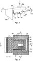
- the Figures 2 to 5 represent a device 30 for the extraction of high temperature granular mineral matter contained in a decarbonation furnace and the transfer of these granular mineral matter in a clinker oven.
- the temperature of the mineral materials contained in the decarbonation furnace is of the order of 1000 ° C.
- the device 30 comprises a fixed upper part 32 and a movable lower part 34 delimiting a duct 36 (shown in FIGS. Figures 4 and 5 ) for the flow of granular mineral matter.
- the duct 36 is provided with an inlet mouth 36a connected to the decarbonation furnace and an outlet mouth 36b connected to the clinker oven.
- the inlet 36a and outlet 36b mouths are offset vertically and horizontally.
- the fixed part 32 comprises a top wall 46, lateral walls 48 parallel to a direction 50, and a lateral wall 52 transverse to the direction 50 connecting the side walls 48.
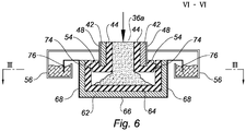
- the side walls 48 have, near their lower edges, ribs 54 (shown in FIG. figure 6 ) formed in the coatings 44.
- the ribs 54 are parallel to the direction 50. The function of the ribs 54 will appear thereafter.
- the stationary portion 32 further includes a channel 56 extending from the sidewalls 48 and 52, and facing downwardly.
- the channel 56 is shaped in 'U' in plan view (as shown in FIG. figure 3 ).
- the channel 56 contains a fluid, such as water or oil, or a granular composition, such as sand. The function of the channel 56 will appear later.
- the movable portion 34 is alternately movable in the direction 50 between an advanced position (shown in FIG. figure 4 ) and a retracted position (shown in figure 5 ), to allow the transfer of the granular minerals in the conduit 36 by reciprocating.
- the movable portion 34 comprises a bottom wall or sole 66, side walls 68 (shown in FIG. figure 6 ) parallel to the direction 50, and a lateral wall 70 transverse to the direction 50 connecting the side walls 68.
- the hearth 66 has an upstream end 66a and a downstream end 66b.
- the hearth 66 is inclined from top to bottom, from its upstream end 66a to its downstream end 66b.
- upstream and downstream are used with reference to the direction of flow of the granular mineral matter in the conduit 36.
- the upstream end 66a extends plumb with the inlet mouth 36a of the duct 36.
- the upstream end 36a comprises a redent 72 transverse to the direction 50.
- the downstream end 66b is turned towards the outlet mouth 36b of the duct 36.
- the side walls 68 each have an upstream end and a downstream end.
- the side walls 68 have, near their upper edges, grooves 74 (shown in FIG. figure 6 ) formed in the coatings 64 of refractory material.
- the grooves 74 are parallel to the direction 50. These grooves 74 are arranged to cooperate without contact with, respectively, the ribs 54 formed in the coating 44 of refractory material of the fixed part 32.
- the movable portion 34 also includes a return 76 extending from the side walls 68 and 70, facing downwards, and shaped as 'U' in plan view (as shown in FIG. figure 3 ).
- the channel 56 and the return 76 are arranged in such a way that the channel 56 surrounds the lateral walls 68 and 70 of the mobile part 40 (as shown in FIG. figure 3 ), and that the lower edge of the return 76 is immersed in the fluid or the granular composition, and can move inside the channel 56 without contact therewith, during the reciprocating movement of the movable part 34 in position forward and backward.
- the level of fluid or sand is such that when the reciprocating displacement of the movable portion 34, the lower edge of the return 76 is permanently immersed in the fluid or sand.
- baffles formed by the ribs 54 and grooves 74 make it possible to limit the depression exerted on the channel 56 and the return 76.
- the device 30 comprises reciprocating means 78 of the mobile part 34.
- These reciprocating means 78 comprise for example a pneumatic cylinder, a hydraulic cylinder or a linkage mechanism associated with a motor.
- the device 30 comprises guide means 80 of the mobile part 34 relative to the fixed part 32.
- These guide means 80 comprise for example a plurality of rollers fixed under the sole 66 of the movable part and engaged in rails parallel to the sole 66.
- the device 30 comprises a bellows 82 textile resistant to high temperatures.
- the bellows is made of ceramic fibers, such as the fibers known as Hytex 2500 or Nextel, for example.
- the bellows 82 is connected on the one hand to the fixed part 32 and on the other hand to the downstream ends of the bottom wall 66 and the side walls 68 of the mobile part 34.
- the bellows 82 is capable of extending, and alternately to contract, in response to the reciprocating movement of the movable portion 34 in the retracted position and in the advanced position.
- the bellows 82 has a general shape of 'U', in a vertical plane.
- the jack 78 animates the moving part 34 of a reciprocating movement between its advanced position and its retracted position.
- the moving part 34 When the moving part 34 is moved from its advanced position to its retracted position (as shown in FIG. figure 5 ), the granular mineral materials from the decarbonation furnace, brought by the inlet mouth 36a, fall by gravity onto the bottom wall 66 of the movable part 34, downstream of the redent 72.
- the redent 72 pushes the granular mineral materials towards the outlet mouth 36b.
- An increase in frequency increases the extraction rate.
- a decrease in the frequency reduces the extraction rate.
- a drawer extractor according to the invention can, for example be installed at the foot of a straight briquetted oven 75 cm in diameter and 3m high.
- the extractor can have an overall width of 1.25 m and an overall length of 1.60 m.
- the sole of the extractor can have a length of 1.40 m and a width of 0.85 m.
- the stroke of the extractor can be 40 mm and each round trip can extract about 5kg of material at high temperature, for example of the order of 1200 ° C.
- This extractor can be used for the extraction of granular mineral matter at high temperature, of the order of 1250 to 1450 ° C, contained in a clinkerisation furnace and the transfer of these granular mineral matter in a cooler.
- the invention is not limited to the sole embodiment of the device described above by way of example, it encompasses all the variants, in the context of the claims below. attached. It is for example possible to add seals, and additional baffles to prevent heat loss and ambient air inlets when the device is in depression relative to the atmosphere.
- the sole is not necessarily inclined but could be horizontal.
Landscapes
- Engineering & Computer Science (AREA)
- Chemical & Material Sciences (AREA)
- Ceramic Engineering (AREA)
- Physics & Mathematics (AREA)
- Thermal Sciences (AREA)
- General Engineering & Computer Science (AREA)
- Mechanical Engineering (AREA)
- Materials Engineering (AREA)
- Structural Engineering (AREA)
- Organic Chemistry (AREA)
- Furnace Details (AREA)
- Furnace Charging Or Discharging (AREA)
- Crucibles And Fluidized-Bed Furnaces (AREA)
Claims (10)
- Abziehvorrichtung mit Schubkasten (30) zum Abziehen und Transferieren von körnigen mineralischen Stoffen mit hoher Temperatur, die in einem ersten Behältnis enthalten sind, umfassend:- einen oberen festen Abschnitt (32) und einen unteren beweglichen Abschnitt (34), die einen Kanal (36) begrenzen, wobei dieser Kanal (36) mit einer Eintrittsmündung (36a), die an das erste Behältnis angeschlossen werden kann, und mit einer Austrittsmündung (36b) versehen ist, wobei die Eintritts-(36a) und Austrittsmündung (36b) horizontal und vertikal versetzt sind;
wobei der untere bewegliche Abschnitt (34) in einer bestimmten Richtung (50) wechselweise zwischen einer vorgerückten Stellung und einer zurückgezogenen Stellung verschiebbar ist, um das Abfließen der körnigen mineralischen Stoffe in den Kanal (36) zu ermöglichen; und- Mittel zum Verschieben und Führen (78, 80) des beweglichen Abschnitts (34) relativ zu dem festen Abschnitt (32);dadurch gekennzeichnet, dass der feste Abschnitt (32) und der bewegliche Abschnitt (34) jeder eine metallische Außenhülle (38; 58) und eine Innenhülle (40; 60) umfassen, die durch Stapelung ausgeführt ist von mindestens:- einer ersten Verkleidung (42; 62) aus einem thermisch isolierenden Material, die auf der metallischen Außenhülle (38; 58) montiert ist; und- einer zweiten Verkleidung (44; 64) aus einem feuerfesten Material, die auf der ersten Verkleidung (42; 62) montiert ist. - Abziehvorrichtung mit Schubkasten (30) nach Anspruch 1, dadurch gekennzeichnet, dass der bewegliche Abschnitt (34) eine Bodenwandung (66) oder Sohle umfasst, die ein stromaufwärtiges Ende (66a) lotrecht zur Eintrittsmündung (36a) und ein stromabwärtiges Ende (66b) aufweist, das der Austrittsmündung (36b) zugewandt ist;
und dadurch, dass die Sohle (66) von ihrem stromaufwärtigen Ende (66a) zu ihrem stromabwärtigen Ende (66b) von oben nach unten geneigt ist. - Abziehvorrichtung mit Schubkasten nach Anspruch 2, dadurch gekennzeichnet, dass das stromaufwärtige Ende (66a) der Sohle (66) eine Stufe (72) quer zur Verschieberichtung (50) des beweglichen Abschnitts (34) umfasst.
- Abziehvorrichtung mit Schubkasten nach einem der Ansprüche 1 bis 3, dadurch gekennzeichnet, dass sie Dichtungsmittel umfasst, die zwischen und/oder um dem/den festen (32) und beweglichen Abschnitt (34) angeordnet sind, derart, dass der Kanal (36) hermetisch geschlossen ist.
- Abziehvorrichtung mit Schubkasten nach einem der Ansprüche 2 oder 3 in Kombination mit Anspruch 4, dadurch gekennzeichnet, dass der bewegliche Abschnitt (34) erste und zweite Seitenwandungen (68) umfasst, die zu seiner Verschieberichtung (50) parallel sind, wobei diese erste und zweite Seitenwandung (68) jede ein stromaufwärtiges Ende und ein stromabwärtiges Ende aufweisen; und
dadurch, dass die Dichtungsmittel einen Balg (82) umfassen, der einerseits mit dem festen Abschnitt (32) und andererseits mit den stromabwärtigen Enden der Bodenwandung (66) und der ersten und zweiten Seitenwandung (68) des beweglichen Abschnitts (34) verbunden ist. - Abziehvorrichtung mit Schubkasten nach Anspruch 4 oder 5, dadurch gekennzeichnet, dass der feste Abschnitt (32) erste und zweite Seitenwandungen (48) umfasst, die zur Verschieberichtung (50) des beweglichen Abschnitts (34) parallel sind;
dadurch, dass die erste und zweite Seitenwandung (68) des beweglichen Abschnitts (34) in der Nähe ihrer Oberkanten mindestens eine Rille (74) oder Rippe aufweisen, die in der Verkleidung aus feuerfestem Material (64) parallel zur Verschieberichtung (50) des beweglichen Abschnitts (34) gebildet ist; und
dadurch, dass die erste und zweite Seitenwandung (48) des festen Teils in der Nähe ihrer Unterkanten mindestens eine Rippe (54) oder Rille aufweisen, die in der Verkleidung aus feuerfestem Material (44) parallel zur Verschieberichtung (50) des beweglichen Abschnitts (34) gebildet und dafür eingerichtet ist, berührungslos mit der Rille (74) bzw. Rippe, die in der Verkleidung aus feuerfestem Material (64) des beweglichen Abschnitts (34) gebildet ist, zusammenzuwirken. - Abziehvorrichtung mit Schubkasten nach einem der Ansprüche 4 bis 6, dadurch gekennzeichnet, dass der bewegliche Abschnitt (34) eine dritte Seitenwandung (70) quer zu seiner Verschieberichtung (50) umfasst, die die erste und zweite Seitenwandung (68) miteinander verbindet; und
dadurch, dass der feste Abschnitt (32) eine dritte Seitenwandung (52) quer zur Verschieberichtung (50) des beweglichen Abschnitts (34) umfasst, die die erste und zweite Seitenwandung (48) miteinander verbindet. - Abziehvorrichtung mit Schubkasten nach Anspruch 7, dadurch gekennzeichnet, dass die Dichtungsmittel umfassen:- eine in Draufsicht als "U" ausgebildete Rinne (56), die sich von der ersten, zweiten und dritten Seitenwandung (48, 52) des festen Abschnitts ausgehend erstreckt, die die erste, zweite und dritte Seitenwandung (68, 70) des beweglichen Abschnitts (34) umgibt und die eine Flüssigkeit, wie Wasser oder Öl, oder eine körnige Zusammensetzung wie Sand enthält;- eine in die Flüssigkeit oder die körnige Zusammensetzung eingetauchte Rückwendung (76), die sich von der ersten, zweiten und dritten Seitenwandung (68, 70) des beweglichen Abschnitts (34) ausgehend erstreckt; unddadurch, dass die Rückwendung (76) dafür eingerichtet ist, sich im Inneren der Rinne (56) berührungslos mit derselben bei Verschiebung des beweglichen Abschnitts (34) zu verschieben.
- Anlage, dadurch gekennzeichnet, dass sie umfasst:- ein erstes Behältnis, das dafür eingerichtet ist, die körnigen mineralischen Stoffe mit hoher Temperatur zu tragen; und- eine Abziehvorrichtung mit Schubkasten nach einem der Ansprüche 1 bis 8.
- Anlage nach Anspruch 9, dadurch gekennzeichnet, dass sie ein zweites Behältnis zum Aufnehmen der aus dem ersten Behältnis abgezogenen körnigen mineralischen Stoffe umfasst und die Austrittsmündung (36b) des Kanals (36) an dieses zweite Behältnis angeschlossen ist.
Applications Claiming Priority (2)
| Application Number | Priority Date | Filing Date | Title |
|---|---|---|---|
| FR1256892A FR2993644B1 (fr) | 2012-07-17 | 2012-07-17 | Extracteur a tiroir pour l'extraction de matieres minerales a haute temperature |
| PCT/FR2013/051679 WO2014013169A1 (fr) | 2012-07-17 | 2013-07-12 | Extracteur a tiroir pour l'extraction de matieres minerales a haute temperature |
Publications (2)
| Publication Number | Publication Date |
|---|---|
| EP2875301A1 EP2875301A1 (de) | 2015-05-27 |
| EP2875301B1 true EP2875301B1 (de) | 2017-12-06 |
Family
ID=46963907
Family Applications (1)
| Application Number | Title | Priority Date | Filing Date |
|---|---|---|---|
| EP13747442.5A Active EP2875301B1 (de) | 2012-07-17 | 2013-07-12 | Verschiebbarer extraktor |
Country Status (6)
| Country | Link |
|---|---|
| US (1) | US10113798B2 (de) |
| EP (1) | EP2875301B1 (de) |
| CA (1) | CA2877064A1 (de) |
| FR (1) | FR2993644B1 (de) |
| IN (1) | IN2014DN10586A (de) |
| WO (1) | WO2014013169A1 (de) |
Family Cites Families (5)
| Publication number | Priority date | Publication date | Assignee | Title |
|---|---|---|---|---|
| US4226564A (en) * | 1977-05-24 | 1980-10-07 | Asahi Glass Company, Limited | Apparatus for feeding glass batch materials into a glass melting furnace |
| US5151000A (en) * | 1991-06-24 | 1992-09-29 | Rod Geraghty | Pellet stove feeder |
| US5254151A (en) * | 1992-06-02 | 1993-10-19 | Frazier-Simplex, Inc. | Glass batch charger having seals which prevents accumulation of batch |
| DE10323944A1 (de) * | 2003-05-27 | 2004-12-16 | Maerz Ofenbau Ag | Prozessbehälter mit Kühlelementen |
| FR2928643B1 (fr) * | 2008-03-14 | 2011-12-16 | Vicat | Procede de fabrication d'un clinker et installation correspondante |
-
2012
- 2012-07-17 FR FR1256892A patent/FR2993644B1/fr not_active Expired - Fee Related
-
2013
- 2013-07-12 EP EP13747442.5A patent/EP2875301B1/de active Active
- 2013-07-12 CA CA2877064A patent/CA2877064A1/fr not_active Abandoned
- 2013-07-12 IN IN10586DEN2014 patent/IN2014DN10586A/en unknown
- 2013-07-12 WO PCT/FR2013/051679 patent/WO2014013169A1/fr not_active Ceased
- 2013-07-12 US US14/415,727 patent/US10113798B2/en not_active Expired - Fee Related
Also Published As
| Publication number | Publication date |
|---|---|
| FR2993644A1 (fr) | 2014-01-24 |
| US10113798B2 (en) | 2018-10-30 |
| CA2877064A1 (fr) | 2014-01-23 |
| WO2014013169A1 (fr) | 2014-01-23 |
| IN2014DN10586A (de) | 2015-08-28 |
| US20150176902A1 (en) | 2015-06-25 |
| EP2875301A1 (de) | 2015-05-27 |
| FR2993644B1 (fr) | 2014-07-25 |
Similar Documents
| Publication | Publication Date | Title |
|---|---|---|
| EP1485650B1 (de) | Extraktor/kühler für lose materialien durch verwendung eines förderbands, das mit bohrungen und flügeln versehenen platten ausgestattet ist | |
| ITMI951310A1 (it) | Estrattore/raffreddatore di materiali sfusi | |
| WO2012126939A1 (fr) | Dispositif pompe de transfert a pistons, procede de transfert de matiere solide granulaire utilisant un tel dispositif, application du procede a l'alimentation d'un reacteur de gazeification | |
| EP0119115A1 (de) | Wärmeerzeuger zur Aufheizung von Fluiden durch Wärmetausch mittels eines Wirbelbettes und das Verfahren hierzu | |
| FR2993644A1 (fr) | Extracteur a tiroir pour l'extraction de matieres minerales a haute temperature | |
| EP0116142A1 (de) | Kühlvorrichtung für eine Schachtofenbeschickungsanlage | |
| CA1083325A (fr) | Dispositif pour l'alimentation automatique continue en metal liquide des fours equipant les machines a mouler les metaux et alliages | |
| EP1399597A1 (de) | Vorrichtung zum beschicken eines schachtofens | |
| EP1034310B1 (de) | Verfahren zur kühlung einer beschickungsanlage eines schachtofens | |
| WO2005078346A1 (en) | Pre-crushing device for a conveyor/cooler of hot loose materials | |
| FR2517422A1 (fr) | Procede et dispositif de recuperation de gaz combustibles dans un four d'electrometallurgie | |
| BE1022052B1 (fr) | Dispositif de captage de chaleur par conduction et enceinte de refroidissement comportant un tel dispositif | |
| EP0430740A1 (de) | Plattenkühler für Hochöfen und eine aus solchen Kühlelementen zusammengesetzte Einrichtung | |
| LU88172A1 (fr) | Dispositif de répartition de matières poudreuses | |
| EP1412689B1 (de) | Verfahren und vorrichtung zum kühlen von zellen eines kammerofens | |
| FR2930981A1 (fr) | Chaudiere pour combustible solide, liquide ou pulverulent | |
| BE858730A (fr) | Procede et dispositif pour augmenter les echanges calorifiques entre matiere solide et gaz, dans un four rotatif a ciment | |
| FR3007512A1 (fr) | Four droit pour la fabrication d'un clinker | |
| EP3178578B1 (de) | Müllverbrennungsanlage und müllverbrennungsverfahren | |
| FR2537710A1 (fr) | Structure d'entree pour tambours rotatifs pour le traitement thermique de matieres | |
| FR2715215A1 (fr) | Four de cimenterie du type à voie humide. | |
| FR2993645A1 (fr) | Four droit pour la fabrication d'un clinker | |
| BE627907A (de) | ||
| FR2928447A1 (fr) | Four tunnel | |
| FR2588942A1 (fr) | Foyer universel pour combustibles solides |
Legal Events
| Date | Code | Title | Description |
|---|---|---|---|
| PUAI | Public reference made under article 153(3) epc to a published international application that has entered the european phase |
Free format text: ORIGINAL CODE: 0009012 |
|
| 17P | Request for examination filed |
Effective date: 20141119 |
|
| AK | Designated contracting states |
Kind code of ref document: A1 Designated state(s): AL AT BE BG CH CY CZ DE DK EE ES FI FR GB GR HR HU IE IS IT LI LT LU LV MC MK MT NL NO PL PT RO RS SE SI SK SM TR |
|
| AX | Request for extension of the european patent |
Extension state: BA ME |
|
| DAX | Request for extension of the european patent (deleted) | ||
| GRAP | Despatch of communication of intention to grant a patent |
Free format text: ORIGINAL CODE: EPIDOSNIGR1 |
|
| INTG | Intention to grant announced |
Effective date: 20170706 |
|
| GRAS | Grant fee paid |
Free format text: ORIGINAL CODE: EPIDOSNIGR3 |
|
| GRAA | (expected) grant |
Free format text: ORIGINAL CODE: 0009210 |
|
| AK | Designated contracting states |
Kind code of ref document: B1 Designated state(s): AL AT BE BG CH CY CZ DE DK EE ES FI FR GB GR HR HU IE IS IT LI LT LU LV MC MK MT NL NO PL PT RO RS SE SI SK SM TR |
|
| REG | Reference to a national code |
Ref country code: GB Ref legal event code: FG4D Free format text: NOT ENGLISH |
|
| REG | Reference to a national code |
Ref country code: AT Ref legal event code: REF Ref document number: 952762 Country of ref document: AT Kind code of ref document: T Effective date: 20171215 Ref country code: CH Ref legal event code: EP |
|
| REG | Reference to a national code |
Ref country code: IE Ref legal event code: FG4D Free format text: LANGUAGE OF EP DOCUMENT: FRENCH |
|
| REG | Reference to a national code |
Ref country code: DE Ref legal event code: R096 Ref document number: 602013030434 Country of ref document: DE |
|
| REG | Reference to a national code |
Ref country code: NL Ref legal event code: MP Effective date: 20171206 |
|
| REG | Reference to a national code |
Ref country code: LT Ref legal event code: MG4D |
|
| PG25 | Lapsed in a contracting state [announced via postgrant information from national office to epo] |
Ref country code: SE Free format text: LAPSE BECAUSE OF FAILURE TO SUBMIT A TRANSLATION OF THE DESCRIPTION OR TO PAY THE FEE WITHIN THE PRESCRIBED TIME-LIMIT Effective date: 20171206 Ref country code: NO Free format text: LAPSE BECAUSE OF FAILURE TO SUBMIT A TRANSLATION OF THE DESCRIPTION OR TO PAY THE FEE WITHIN THE PRESCRIBED TIME-LIMIT Effective date: 20180306 Ref country code: FI Free format text: LAPSE BECAUSE OF FAILURE TO SUBMIT A TRANSLATION OF THE DESCRIPTION OR TO PAY THE FEE WITHIN THE PRESCRIBED TIME-LIMIT Effective date: 20171206 Ref country code: ES Free format text: LAPSE BECAUSE OF FAILURE TO SUBMIT A TRANSLATION OF THE DESCRIPTION OR TO PAY THE FEE WITHIN THE PRESCRIBED TIME-LIMIT Effective date: 20171206 Ref country code: LT Free format text: LAPSE BECAUSE OF FAILURE TO SUBMIT A TRANSLATION OF THE DESCRIPTION OR TO PAY THE FEE WITHIN THE PRESCRIBED TIME-LIMIT Effective date: 20171206 |
|
| REG | Reference to a national code |
Ref country code: AT Ref legal event code: MK05 Ref document number: 952762 Country of ref document: AT Kind code of ref document: T Effective date: 20171206 |
|
| PG25 | Lapsed in a contracting state [announced via postgrant information from national office to epo] |
Ref country code: LV Free format text: LAPSE BECAUSE OF FAILURE TO SUBMIT A TRANSLATION OF THE DESCRIPTION OR TO PAY THE FEE WITHIN THE PRESCRIBED TIME-LIMIT Effective date: 20171206 Ref country code: BG Free format text: LAPSE BECAUSE OF FAILURE TO SUBMIT A TRANSLATION OF THE DESCRIPTION OR TO PAY THE FEE WITHIN THE PRESCRIBED TIME-LIMIT Effective date: 20180306 Ref country code: GR Free format text: LAPSE BECAUSE OF FAILURE TO SUBMIT A TRANSLATION OF THE DESCRIPTION OR TO PAY THE FEE WITHIN THE PRESCRIBED TIME-LIMIT Effective date: 20180307 Ref country code: HR Free format text: LAPSE BECAUSE OF FAILURE TO SUBMIT A TRANSLATION OF THE DESCRIPTION OR TO PAY THE FEE WITHIN THE PRESCRIBED TIME-LIMIT Effective date: 20171206 Ref country code: RS Free format text: LAPSE BECAUSE OF FAILURE TO SUBMIT A TRANSLATION OF THE DESCRIPTION OR TO PAY THE FEE WITHIN THE PRESCRIBED TIME-LIMIT Effective date: 20171206 |
|
| PG25 | Lapsed in a contracting state [announced via postgrant information from national office to epo] |
Ref country code: NL Free format text: LAPSE BECAUSE OF FAILURE TO SUBMIT A TRANSLATION OF THE DESCRIPTION OR TO PAY THE FEE WITHIN THE PRESCRIBED TIME-LIMIT Effective date: 20171206 |
|
| PG25 | Lapsed in a contracting state [announced via postgrant information from national office to epo] |
Ref country code: SK Free format text: LAPSE BECAUSE OF FAILURE TO SUBMIT A TRANSLATION OF THE DESCRIPTION OR TO PAY THE FEE WITHIN THE PRESCRIBED TIME-LIMIT Effective date: 20171206 Ref country code: EE Free format text: LAPSE BECAUSE OF FAILURE TO SUBMIT A TRANSLATION OF THE DESCRIPTION OR TO PAY THE FEE WITHIN THE PRESCRIBED TIME-LIMIT Effective date: 20171206 Ref country code: CZ Free format text: LAPSE BECAUSE OF FAILURE TO SUBMIT A TRANSLATION OF THE DESCRIPTION OR TO PAY THE FEE WITHIN THE PRESCRIBED TIME-LIMIT Effective date: 20171206 |
|
| PG25 | Lapsed in a contracting state [announced via postgrant information from national office to epo] |
Ref country code: AT Free format text: LAPSE BECAUSE OF FAILURE TO SUBMIT A TRANSLATION OF THE DESCRIPTION OR TO PAY THE FEE WITHIN THE PRESCRIBED TIME-LIMIT Effective date: 20171206 Ref country code: SM Free format text: LAPSE BECAUSE OF FAILURE TO SUBMIT A TRANSLATION OF THE DESCRIPTION OR TO PAY THE FEE WITHIN THE PRESCRIBED TIME-LIMIT Effective date: 20171206 Ref country code: PL Free format text: LAPSE BECAUSE OF FAILURE TO SUBMIT A TRANSLATION OF THE DESCRIPTION OR TO PAY THE FEE WITHIN THE PRESCRIBED TIME-LIMIT Effective date: 20171206 Ref country code: IT Free format text: LAPSE BECAUSE OF FAILURE TO SUBMIT A TRANSLATION OF THE DESCRIPTION OR TO PAY THE FEE WITHIN THE PRESCRIBED TIME-LIMIT Effective date: 20171206 Ref country code: RO Free format text: LAPSE BECAUSE OF FAILURE TO SUBMIT A TRANSLATION OF THE DESCRIPTION OR TO PAY THE FEE WITHIN THE PRESCRIBED TIME-LIMIT Effective date: 20171206 |
|
| REG | Reference to a national code |
Ref country code: DE Ref legal event code: R097 Ref document number: 602013030434 Country of ref document: DE |
|
| PG25 | Lapsed in a contracting state [announced via postgrant information from national office to epo] |
Ref country code: MT Free format text: LAPSE BECAUSE OF FAILURE TO SUBMIT A TRANSLATION OF THE DESCRIPTION OR TO PAY THE FEE WITHIN THE PRESCRIBED TIME-LIMIT Effective date: 20171206 |
|
| PLBE | No opposition filed within time limit |
Free format text: ORIGINAL CODE: 0009261 |
|
| STAA | Information on the status of an ep patent application or granted ep patent |
Free format text: STATUS: NO OPPOSITION FILED WITHIN TIME LIMIT |
|
| REG | Reference to a national code |
Ref country code: FR Ref legal event code: PLFP Year of fee payment: 6 |
|
| 26N | No opposition filed |
Effective date: 20180907 |
|
| PG25 | Lapsed in a contracting state [announced via postgrant information from national office to epo] |
Ref country code: SI Free format text: LAPSE BECAUSE OF FAILURE TO SUBMIT A TRANSLATION OF THE DESCRIPTION OR TO PAY THE FEE WITHIN THE PRESCRIBED TIME-LIMIT Effective date: 20171206 Ref country code: DK Free format text: LAPSE BECAUSE OF FAILURE TO SUBMIT A TRANSLATION OF THE DESCRIPTION OR TO PAY THE FEE WITHIN THE PRESCRIBED TIME-LIMIT Effective date: 20171206 |
|
| REG | Reference to a national code |
Ref country code: DE Ref legal event code: R119 Ref document number: 602013030434 Country of ref document: DE |
|
| REG | Reference to a national code |
Ref country code: CH Ref legal event code: PL |
|
| GBPC | Gb: european patent ceased through non-payment of renewal fee |
Effective date: 20180712 |
|
| PG25 | Lapsed in a contracting state [announced via postgrant information from national office to epo] |
Ref country code: MC Free format text: LAPSE BECAUSE OF FAILURE TO SUBMIT A TRANSLATION OF THE DESCRIPTION OR TO PAY THE FEE WITHIN THE PRESCRIBED TIME-LIMIT Effective date: 20171206 Ref country code: LU Free format text: LAPSE BECAUSE OF NON-PAYMENT OF DUE FEES Effective date: 20180712 |
|
| REG | Reference to a national code |
Ref country code: BE Ref legal event code: MM Effective date: 20180731 |
|
| REG | Reference to a national code |
Ref country code: IE Ref legal event code: MM4A |
|
| PG25 | Lapsed in a contracting state [announced via postgrant information from national office to epo] |
Ref country code: IE Free format text: LAPSE BECAUSE OF NON-PAYMENT OF DUE FEES Effective date: 20180712 Ref country code: CH Free format text: LAPSE BECAUSE OF NON-PAYMENT OF DUE FEES Effective date: 20180731 Ref country code: LI Free format text: LAPSE BECAUSE OF NON-PAYMENT OF DUE FEES Effective date: 20180731 Ref country code: GB Free format text: LAPSE BECAUSE OF NON-PAYMENT OF DUE FEES Effective date: 20180712 Ref country code: DE Free format text: LAPSE BECAUSE OF NON-PAYMENT OF DUE FEES Effective date: 20190201 |
|
| PG25 | Lapsed in a contracting state [announced via postgrant information from national office to epo] |
Ref country code: BE Free format text: LAPSE BECAUSE OF NON-PAYMENT OF DUE FEES Effective date: 20180731 |
|
| PG25 | Lapsed in a contracting state [announced via postgrant information from national office to epo] |
Ref country code: TR Free format text: LAPSE BECAUSE OF FAILURE TO SUBMIT A TRANSLATION OF THE DESCRIPTION OR TO PAY THE FEE WITHIN THE PRESCRIBED TIME-LIMIT Effective date: 20171206 |
|
| PG25 | Lapsed in a contracting state [announced via postgrant information from national office to epo] |
Ref country code: HU Free format text: LAPSE BECAUSE OF FAILURE TO SUBMIT A TRANSLATION OF THE DESCRIPTION OR TO PAY THE FEE WITHIN THE PRESCRIBED TIME-LIMIT; INVALID AB INITIO Effective date: 20130712 Ref country code: PT Free format text: LAPSE BECAUSE OF FAILURE TO SUBMIT A TRANSLATION OF THE DESCRIPTION OR TO PAY THE FEE WITHIN THE PRESCRIBED TIME-LIMIT Effective date: 20171206 |
|
| PG25 | Lapsed in a contracting state [announced via postgrant information from national office to epo] |
Ref country code: MK Free format text: LAPSE BECAUSE OF NON-PAYMENT OF DUE FEES Effective date: 20171206 Ref country code: CY Free format text: LAPSE BECAUSE OF FAILURE TO SUBMIT A TRANSLATION OF THE DESCRIPTION OR TO PAY THE FEE WITHIN THE PRESCRIBED TIME-LIMIT Effective date: 20171206 |
|
| PG25 | Lapsed in a contracting state [announced via postgrant information from national office to epo] |
Ref country code: AL Free format text: LAPSE BECAUSE OF FAILURE TO SUBMIT A TRANSLATION OF THE DESCRIPTION OR TO PAY THE FEE WITHIN THE PRESCRIBED TIME-LIMIT Effective date: 20171206 Ref country code: IS Free format text: LAPSE BECAUSE OF FAILURE TO SUBMIT A TRANSLATION OF THE DESCRIPTION OR TO PAY THE FEE WITHIN THE PRESCRIBED TIME-LIMIT Effective date: 20180406 |
|
| PGFP | Annual fee paid to national office [announced via postgrant information from national office to epo] |
Ref country code: FR Payment date: 20250618 Year of fee payment: 13 |