EP2874264A1 - Système de gestion de multiples sources de puissance à la demande, programme de système de gestion de multiples sources de puissance à la demande et support d'enregistrement lisible par ordinateur sur lequel ledit programme est enregistré - Google Patents
Système de gestion de multiples sources de puissance à la demande, programme de système de gestion de multiples sources de puissance à la demande et support d'enregistrement lisible par ordinateur sur lequel ledit programme est enregistré Download PDFInfo
- Publication number
- EP2874264A1 EP2874264A1 EP20130817253 EP13817253A EP2874264A1 EP 2874264 A1 EP2874264 A1 EP 2874264A1 EP 20130817253 EP20130817253 EP 20130817253 EP 13817253 A EP13817253 A EP 13817253A EP 2874264 A1 EP2874264 A1 EP 2874264A1
- Authority
- EP
- European Patent Office
- Prior art keywords
- power
- power source
- plan
- time
- supply
- Prior art date
- Legal status (The legal status is an assumption and is not a legal conclusion. Google has not performed a legal analysis and makes no representation as to the accuracy of the status listed.)
- Withdrawn
Links
- 238000000034 method Methods 0.000 claims abstract description 97
- 230000008569 process Effects 0.000 claims abstract description 66
- 230000014509 gene expression Effects 0.000 claims abstract description 50
- 239000003990 capacitor Substances 0.000 claims abstract description 9
- 230000004044 response Effects 0.000 abstract description 11
- 238000007726 management method Methods 0.000 description 38
- 238000010586 diagram Methods 0.000 description 37
- 230000009467 reduction Effects 0.000 description 34
- 230000006870 function Effects 0.000 description 30
- 238000001994 activation Methods 0.000 description 22
- 230000004913 activation Effects 0.000 description 16
- 230000008859 change Effects 0.000 description 13
- 238000004422 calculation algorithm Methods 0.000 description 11
- 238000012544 monitoring process Methods 0.000 description 11
- 238000012545 processing Methods 0.000 description 11
- 230000007704 transition Effects 0.000 description 11
- 230000000052 comparative effect Effects 0.000 description 9
- 238000004891 communication Methods 0.000 description 8
- 238000002474 experimental method Methods 0.000 description 7
- 238000009826 distribution Methods 0.000 description 6
- 238000003780 insertion Methods 0.000 description 6
- 230000037431 insertion Effects 0.000 description 6
- 230000000737 periodic effect Effects 0.000 description 6
- 238000007781 pre-processing Methods 0.000 description 6
- 241000209094 Oryza Species 0.000 description 5
- 235000007164 Oryza sativa Nutrition 0.000 description 5
- 235000009566 rice Nutrition 0.000 description 5
- 239000008186 active pharmaceutical agent Substances 0.000 description 4
- 238000011160 research Methods 0.000 description 4
- 238000004088 simulation Methods 0.000 description 4
- XLYOFNOQVPJJNP-UHFFFAOYSA-N water Substances O XLYOFNOQVPJJNP-UHFFFAOYSA-N 0.000 description 4
- 230000009471 action Effects 0.000 description 3
- 238000013459 approach Methods 0.000 description 3
- 238000007796 conventional method Methods 0.000 description 3
- 238000012937 correction Methods 0.000 description 3
- 238000013500 data storage Methods 0.000 description 3
- 230000007423 decrease Effects 0.000 description 3
- 238000013461 design Methods 0.000 description 3
- 238000009434 installation Methods 0.000 description 3
- 239000004065 semiconductor Substances 0.000 description 3
- 238000012360 testing method Methods 0.000 description 3
- 238000009827 uniform distribution Methods 0.000 description 3
- 238000005406 washing Methods 0.000 description 3
- 238000012935 Averaging Methods 0.000 description 2
- 230000003044 adaptive effect Effects 0.000 description 2
- 238000001514 detection method Methods 0.000 description 2
- 238000005315 distribution function Methods 0.000 description 2
- 230000005611 electricity Effects 0.000 description 2
- 238000011010 flushing procedure Methods 0.000 description 2
- 239000000446 fuel Substances 0.000 description 2
- 101150070878 Ereg gene Proteins 0.000 description 1
- 230000001174 ascending effect Effects 0.000 description 1
- 230000008901 benefit Effects 0.000 description 1
- 230000005540 biological transmission Effects 0.000 description 1
- 230000003247 decreasing effect Effects 0.000 description 1
- 230000003111 delayed effect Effects 0.000 description 1
- 238000007599 discharging Methods 0.000 description 1
- 230000000694 effects Effects 0.000 description 1
- 230000001771 impaired effect Effects 0.000 description 1
- 230000010365 information processing Effects 0.000 description 1
- 230000002401 inhibitory effect Effects 0.000 description 1
- 238000005259 measurement Methods 0.000 description 1
- 238000012806 monitoring device Methods 0.000 description 1
- 230000006641 stabilisation Effects 0.000 description 1
- 238000011105 stabilization Methods 0.000 description 1
- 239000000725 suspension Substances 0.000 description 1
Images


Classifications
-
- H—ELECTRICITY
- H02—GENERATION; CONVERSION OR DISTRIBUTION OF ELECTRIC POWER
- H02J—CIRCUIT ARRANGEMENTS OR SYSTEMS FOR SUPPLYING OR DISTRIBUTING ELECTRIC POWER; SYSTEMS FOR STORING ELECTRIC ENERGY
- H02J3/00—Circuit arrangements for ac mains or ac distribution networks
- H02J3/28—Arrangements for balancing of the load in a network by storage of energy
- H02J3/32—Arrangements for balancing of the load in a network by storage of energy using batteries with converting means
-
- H—ELECTRICITY
- H02—GENERATION; CONVERSION OR DISTRIBUTION OF ELECTRIC POWER
- H02J—CIRCUIT ARRANGEMENTS OR SYSTEMS FOR SUPPLYING OR DISTRIBUTING ELECTRIC POWER; SYSTEMS FOR STORING ELECTRIC ENERGY
- H02J3/00—Circuit arrangements for ac mains or ac distribution networks
- H02J3/12—Circuit arrangements for ac mains or ac distribution networks for adjusting voltage in ac networks by changing a characteristic of the network load
- H02J3/14—Circuit arrangements for ac mains or ac distribution networks for adjusting voltage in ac networks by changing a characteristic of the network load by switching loads on to, or off from, network, e.g. progressively balanced loading
-
- H—ELECTRICITY
- H02—GENERATION; CONVERSION OR DISTRIBUTION OF ELECTRIC POWER
- H02J—CIRCUIT ARRANGEMENTS OR SYSTEMS FOR SUPPLYING OR DISTRIBUTING ELECTRIC POWER; SYSTEMS FOR STORING ELECTRIC ENERGY
- H02J3/00—Circuit arrangements for ac mains or ac distribution networks
- H02J3/003—Load forecast, e.g. methods or systems for forecasting future load demand
-
- G—PHYSICS
- G05—CONTROLLING; REGULATING
- G05B—CONTROL OR REGULATING SYSTEMS IN GENERAL; FUNCTIONAL ELEMENTS OF SUCH SYSTEMS; MONITORING OR TESTING ARRANGEMENTS FOR SUCH SYSTEMS OR ELEMENTS
- G05B15/00—Systems controlled by a computer
- G05B15/02—Systems controlled by a computer electric
-
- G—PHYSICS
- G06—COMPUTING; CALCULATING OR COUNTING
- G06Q—INFORMATION AND COMMUNICATION TECHNOLOGY [ICT] SPECIALLY ADAPTED FOR ADMINISTRATIVE, COMMERCIAL, FINANCIAL, MANAGERIAL OR SUPERVISORY PURPOSES; SYSTEMS OR METHODS SPECIALLY ADAPTED FOR ADMINISTRATIVE, COMMERCIAL, FINANCIAL, MANAGERIAL OR SUPERVISORY PURPOSES, NOT OTHERWISE PROVIDED FOR
- G06Q10/00—Administration; Management
- G06Q10/04—Forecasting or optimisation specially adapted for administrative or management purposes, e.g. linear programming or "cutting stock problem"
-
- G—PHYSICS
- G06—COMPUTING; CALCULATING OR COUNTING
- G06Q—INFORMATION AND COMMUNICATION TECHNOLOGY [ICT] SPECIALLY ADAPTED FOR ADMINISTRATIVE, COMMERCIAL, FINANCIAL, MANAGERIAL OR SUPERVISORY PURPOSES; SYSTEMS OR METHODS SPECIALLY ADAPTED FOR ADMINISTRATIVE, COMMERCIAL, FINANCIAL, MANAGERIAL OR SUPERVISORY PURPOSES, NOT OTHERWISE PROVIDED FOR
- G06Q10/00—Administration; Management
- G06Q10/06—Resources, workflows, human or project management; Enterprise or organisation planning; Enterprise or organisation modelling
- G06Q10/063—Operations research, analysis or management
- G06Q10/0631—Resource planning, allocation, distributing or scheduling for enterprises or organisations
- G06Q10/06312—Adjustment or analysis of established resource schedule, e.g. resource or task levelling, or dynamic rescheduling
-
- G—PHYSICS
- G06—COMPUTING; CALCULATING OR COUNTING
- G06Q—INFORMATION AND COMMUNICATION TECHNOLOGY [ICT] SPECIALLY ADAPTED FOR ADMINISTRATIVE, COMMERCIAL, FINANCIAL, MANAGERIAL OR SUPERVISORY PURPOSES; SYSTEMS OR METHODS SPECIALLY ADAPTED FOR ADMINISTRATIVE, COMMERCIAL, FINANCIAL, MANAGERIAL OR SUPERVISORY PURPOSES, NOT OTHERWISE PROVIDED FOR
- G06Q50/00—Information and communication technology [ICT] specially adapted for implementation of business processes of specific business sectors, e.g. utilities or tourism
- G06Q50/06—Energy or water supply
-
- H—ELECTRICITY
- H02—GENERATION; CONVERSION OR DISTRIBUTION OF ELECTRIC POWER
- H02J—CIRCUIT ARRANGEMENTS OR SYSTEMS FOR SUPPLYING OR DISTRIBUTING ELECTRIC POWER; SYSTEMS FOR STORING ELECTRIC ENERGY
- H02J13/00—Circuit arrangements for providing remote indication of network conditions, e.g. an instantaneous record of the open or closed condition of each circuitbreaker in the network; Circuit arrangements for providing remote control of switching means in a power distribution network, e.g. switching in and out of current consumers by using a pulse code signal carried by the network
-
- H—ELECTRICITY
- H02—GENERATION; CONVERSION OR DISTRIBUTION OF ELECTRIC POWER
- H02J—CIRCUIT ARRANGEMENTS OR SYSTEMS FOR SUPPLYING OR DISTRIBUTING ELECTRIC POWER; SYSTEMS FOR STORING ELECTRIC ENERGY
- H02J3/00—Circuit arrangements for ac mains or ac distribution networks
- H02J3/004—Generation forecast, e.g. methods or systems for forecasting future energy generation
-
- H—ELECTRICITY
- H02—GENERATION; CONVERSION OR DISTRIBUTION OF ELECTRIC POWER
- H02J—CIRCUIT ARRANGEMENTS OR SYSTEMS FOR SUPPLYING OR DISTRIBUTING ELECTRIC POWER; SYSTEMS FOR STORING ELECTRIC ENERGY
- H02J7/00—Circuit arrangements for charging or depolarising batteries or for supplying loads from batteries
- H02J7/0063—Circuit arrangements for charging or depolarising batteries or for supplying loads from batteries with circuits adapted for supplying loads from the battery
-
- G—PHYSICS
- G06—COMPUTING; CALCULATING OR COUNTING
- G06Q—INFORMATION AND COMMUNICATION TECHNOLOGY [ICT] SPECIALLY ADAPTED FOR ADMINISTRATIVE, COMMERCIAL, FINANCIAL, MANAGERIAL OR SUPERVISORY PURPOSES; SYSTEMS OR METHODS SPECIALLY ADAPTED FOR ADMINISTRATIVE, COMMERCIAL, FINANCIAL, MANAGERIAL OR SUPERVISORY PURPOSES, NOT OTHERWISE PROVIDED FOR
- G06Q10/00—Administration; Management
- G06Q10/06—Resources, workflows, human or project management; Enterprise or organisation planning; Enterprise or organisation modelling
-
- H—ELECTRICITY
- H02—GENERATION; CONVERSION OR DISTRIBUTION OF ELECTRIC POWER
- H02J—CIRCUIT ARRANGEMENTS OR SYSTEMS FOR SUPPLYING OR DISTRIBUTING ELECTRIC POWER; SYSTEMS FOR STORING ELECTRIC ENERGY
- H02J7/00—Circuit arrangements for charging or depolarising batteries or for supplying loads from batteries
- H02J7/34—Parallel operation in networks using both storage and other dc sources, e.g. providing buffering
- H02J7/345—Parallel operation in networks using both storage and other dc sources, e.g. providing buffering using capacitors as storage or buffering devices
-
- H—ELECTRICITY
- H02—GENERATION; CONVERSION OR DISTRIBUTION OF ELECTRIC POWER
- H02J—CIRCUIT ARRANGEMENTS OR SYSTEMS FOR SUPPLYING OR DISTRIBUTING ELECTRIC POWER; SYSTEMS FOR STORING ELECTRIC ENERGY
- H02J7/00—Circuit arrangements for charging or depolarising batteries or for supplying loads from batteries
- H02J7/34—Parallel operation in networks using both storage and other dc sources, e.g. providing buffering
- H02J7/35—Parallel operation in networks using both storage and other dc sources, e.g. providing buffering with light sensitive cells
-
- Y—GENERAL TAGGING OF NEW TECHNOLOGICAL DEVELOPMENTS; GENERAL TAGGING OF CROSS-SECTIONAL TECHNOLOGIES SPANNING OVER SEVERAL SECTIONS OF THE IPC; TECHNICAL SUBJECTS COVERED BY FORMER USPC CROSS-REFERENCE ART COLLECTIONS [XRACs] AND DIGESTS
- Y02—TECHNOLOGIES OR APPLICATIONS FOR MITIGATION OR ADAPTATION AGAINST CLIMATE CHANGE
- Y02B—CLIMATE CHANGE MITIGATION TECHNOLOGIES RELATED TO BUILDINGS, e.g. HOUSING, HOUSE APPLIANCES OR RELATED END-USER APPLICATIONS
- Y02B70/00—Technologies for an efficient end-user side electric power management and consumption
- Y02B70/30—Systems integrating technologies related to power network operation and communication or information technologies for improving the carbon footprint of the management of residential or tertiary loads, i.e. smart grids as climate change mitigation technology in the buildings sector, including also the last stages of power distribution and the control, monitoring or operating management systems at local level
- Y02B70/3225—Demand response systems, e.g. load shedding, peak shaving
-
- Y—GENERAL TAGGING OF NEW TECHNOLOGICAL DEVELOPMENTS; GENERAL TAGGING OF CROSS-SECTIONAL TECHNOLOGIES SPANNING OVER SEVERAL SECTIONS OF THE IPC; TECHNICAL SUBJECTS COVERED BY FORMER USPC CROSS-REFERENCE ART COLLECTIONS [XRACs] AND DIGESTS
- Y02—TECHNOLOGIES OR APPLICATIONS FOR MITIGATION OR ADAPTATION AGAINST CLIMATE CHANGE
- Y02B—CLIMATE CHANGE MITIGATION TECHNOLOGIES RELATED TO BUILDINGS, e.g. HOUSING, HOUSE APPLIANCES OR RELATED END-USER APPLICATIONS
- Y02B90/00—Enabling technologies or technologies with a potential or indirect contribution to GHG emissions mitigation
- Y02B90/20—Smart grids as enabling technology in buildings sector
-
- Y—GENERAL TAGGING OF NEW TECHNOLOGICAL DEVELOPMENTS; GENERAL TAGGING OF CROSS-SECTIONAL TECHNOLOGIES SPANNING OVER SEVERAL SECTIONS OF THE IPC; TECHNICAL SUBJECTS COVERED BY FORMER USPC CROSS-REFERENCE ART COLLECTIONS [XRACs] AND DIGESTS
- Y02—TECHNOLOGIES OR APPLICATIONS FOR MITIGATION OR ADAPTATION AGAINST CLIMATE CHANGE
- Y02E—REDUCTION OF GREENHOUSE GAS [GHG] EMISSIONS, RELATED TO ENERGY GENERATION, TRANSMISSION OR DISTRIBUTION
- Y02E40/00—Technologies for an efficient electrical power generation, transmission or distribution
- Y02E40/70—Smart grids as climate change mitigation technology in the energy generation sector
-
- Y—GENERAL TAGGING OF NEW TECHNOLOGICAL DEVELOPMENTS; GENERAL TAGGING OF CROSS-SECTIONAL TECHNOLOGIES SPANNING OVER SEVERAL SECTIONS OF THE IPC; TECHNICAL SUBJECTS COVERED BY FORMER USPC CROSS-REFERENCE ART COLLECTIONS [XRACs] AND DIGESTS
- Y04—INFORMATION OR COMMUNICATION TECHNOLOGIES HAVING AN IMPACT ON OTHER TECHNOLOGY AREAS
- Y04S—SYSTEMS INTEGRATING TECHNOLOGIES RELATED TO POWER NETWORK OPERATION, COMMUNICATION OR INFORMATION TECHNOLOGIES FOR IMPROVING THE ELECTRICAL POWER GENERATION, TRANSMISSION, DISTRIBUTION, MANAGEMENT OR USAGE, i.e. SMART GRIDS
- Y04S10/00—Systems supporting electrical power generation, transmission or distribution
- Y04S10/14—Energy storage units
-
- Y—GENERAL TAGGING OF NEW TECHNOLOGICAL DEVELOPMENTS; GENERAL TAGGING OF CROSS-SECTIONAL TECHNOLOGIES SPANNING OVER SEVERAL SECTIONS OF THE IPC; TECHNICAL SUBJECTS COVERED BY FORMER USPC CROSS-REFERENCE ART COLLECTIONS [XRACs] AND DIGESTS
- Y04—INFORMATION OR COMMUNICATION TECHNOLOGIES HAVING AN IMPACT ON OTHER TECHNOLOGY AREAS
- Y04S—SYSTEMS INTEGRATING TECHNOLOGIES RELATED TO POWER NETWORK OPERATION, COMMUNICATION OR INFORMATION TECHNOLOGIES FOR IMPROVING THE ELECTRICAL POWER GENERATION, TRANSMISSION, DISTRIBUTION, MANAGEMENT OR USAGE, i.e. SMART GRIDS
- Y04S10/00—Systems supporting electrical power generation, transmission or distribution
- Y04S10/50—Systems or methods supporting the power network operation or management, involving a certain degree of interaction with the load-side end user applications
-
- Y—GENERAL TAGGING OF NEW TECHNOLOGICAL DEVELOPMENTS; GENERAL TAGGING OF CROSS-SECTIONAL TECHNOLOGIES SPANNING OVER SEVERAL SECTIONS OF THE IPC; TECHNICAL SUBJECTS COVERED BY FORMER USPC CROSS-REFERENCE ART COLLECTIONS [XRACs] AND DIGESTS
- Y04—INFORMATION OR COMMUNICATION TECHNOLOGIES HAVING AN IMPACT ON OTHER TECHNOLOGY AREAS
- Y04S—SYSTEMS INTEGRATING TECHNOLOGIES RELATED TO POWER NETWORK OPERATION, COMMUNICATION OR INFORMATION TECHNOLOGIES FOR IMPROVING THE ELECTRICAL POWER GENERATION, TRANSMISSION, DISTRIBUTION, MANAGEMENT OR USAGE, i.e. SMART GRIDS
- Y04S20/00—Management or operation of end-user stationary applications or the last stages of power distribution; Controlling, monitoring or operating thereof
- Y04S20/12—Energy storage units, uninterruptible power supply [UPS] systems or standby or emergency generators, e.g. in the last power distribution stages
-
- Y—GENERAL TAGGING OF NEW TECHNOLOGICAL DEVELOPMENTS; GENERAL TAGGING OF CROSS-SECTIONAL TECHNOLOGIES SPANNING OVER SEVERAL SECTIONS OF THE IPC; TECHNICAL SUBJECTS COVERED BY FORMER USPC CROSS-REFERENCE ART COLLECTIONS [XRACs] AND DIGESTS
- Y04—INFORMATION OR COMMUNICATION TECHNOLOGIES HAVING AN IMPACT ON OTHER TECHNOLOGY AREAS
- Y04S—SYSTEMS INTEGRATING TECHNOLOGIES RELATED TO POWER NETWORK OPERATION, COMMUNICATION OR INFORMATION TECHNOLOGIES FOR IMPROVING THE ELECTRICAL POWER GENERATION, TRANSMISSION, DISTRIBUTION, MANAGEMENT OR USAGE, i.e. SMART GRIDS
- Y04S20/00—Management or operation of end-user stationary applications or the last stages of power distribution; Controlling, monitoring or operating thereof
- Y04S20/20—End-user application control systems
- Y04S20/222—Demand response systems, e.g. load shedding, peak shaving
-
- Y—GENERAL TAGGING OF NEW TECHNOLOGICAL DEVELOPMENTS; GENERAL TAGGING OF CROSS-SECTIONAL TECHNOLOGIES SPANNING OVER SEVERAL SECTIONS OF THE IPC; TECHNICAL SUBJECTS COVERED BY FORMER USPC CROSS-REFERENCE ART COLLECTIONS [XRACs] AND DIGESTS
- Y04—INFORMATION OR COMMUNICATION TECHNOLOGIES HAVING AN IMPACT ON OTHER TECHNOLOGY AREAS
- Y04S—SYSTEMS INTEGRATING TECHNOLOGIES RELATED TO POWER NETWORK OPERATION, COMMUNICATION OR INFORMATION TECHNOLOGIES FOR IMPROVING THE ELECTRICAL POWER GENERATION, TRANSMISSION, DISTRIBUTION, MANAGEMENT OR USAGE, i.e. SMART GRIDS
- Y04S20/00—Management or operation of end-user stationary applications or the last stages of power distribution; Controlling, monitoring or operating thereof
- Y04S20/20—End-user application control systems
- Y04S20/242—Home appliances
Definitions
- the present invention relates to a storage battery management system for an on-demand power control system in a home or office network, an on-demand multiple power source management system program, and a computer-readable recording medium recording the program, and more particularly, to an on-demand multiple power source management system, an on-demand multiple power source management system program, and a computer-readable recording medium recording the program that implement a plurality of power sources for commercial power sources without restrictions in peak power, while controlling the supply of power without exceeding an upper limit of power consumption (Wh) by dynamically changing priorities between electric devices, without losing the quality of life (hereinafter, called "QoL”) necessary for the user in daily life.
- Wh upper limit of power consumption
- An on-demand power control system is designed to realize energy management of a household or an office, and the system is intended to shift a supplier-driven "push-type" power network 180 degrees to a user, consumer-led “pull-type".
- the system is a system in which a home server estimates, from the utilization mode of the user, "which request of a device is most important" for power requests of devices that are various home electric products in a household, such as an air conditioner and a lighting, and performs control, that is, Energy on Demand control (hereinafter, called "EoD control”), to supply power first to an important electric device with a high priority.
- EoD control system Energy on Demand control
- the biggest advantage of using the system is that the demand side can realize energy saving and CO 2 emission reduction.
- the EoD control allows a user-driven approach for distributing only power that is cut 20%, and energy saving and CO 2 emission reduction can be realized in the system.
- Patent Literature 1 The following inventions of "Home Network” (see Patent Literature 1) and “Supply and Demand Arbitration System” (see Patent Literature 2) are known as Patent Literature related to the EoD control.
- the home network includes: a server (master); detection means and control means of the server; and a member (slave).
- the server and the member are connected through a LAN.
- n electric devices in a household are connected to sockets through n members.
- the detection means detects operation situations of actually operating m electric devices.
- the control means uses n power data transmitted from the n members to compute the power consumption used in the household, and when the computed total electric energy is equal to or greater than a threshold, outputs, to j members, control signals for controlling the power consumption of j electric devices, in which the operation state changes in steps or continuously among the m electric devices, below the threshold of the total electric energy to control the j members to limit the power.
- the server is a server that preferentially supplies power to electric devices in which the operation state is changed only by On/Off, such as electric devices like a ceiling light, a desktop light, and a coffee maker, to reduce the power consumption below the threshold of the total electric energy.
- the member is called a "smart tap” nowadays, and the smart tap includes: a voltage-current sensor that measures power; a semiconductor relay for controlling power; a ZigBee module for communication; and a microcomputer with a built-in DSP that controls the entire components and that executes internal processing.
- the microcomputer has a function of calculating the power consumption from a current and voltage waveform measured by the voltage-current sensor attached to the smart tap and extracting a little feature amount indicating features of the voltage and current waveform to specify the device from the feature amount by using comparison data saved in advance in an internal memory of the smart tap.
- the data of every period (once/60 seconds) of the power consumption calculated by the microcomputer at 0.5 second intervals is held in the internal memory of the smart tap, and the data is divided into a plurality of packets and transmitted to the server (see Non Patent Literature 1 and 2).
- the supply and demand arbitration system is developed based on a notion that the power supply on the basis of available power on the power source side and power consumption on the device side will be more important when not only solar batteries, but also fuel cells and storage batteries are widely used in general households. Therefore, the supply and demand arbitration system includes: an arbitration server; apparatuses of power sources (commercial power sources, solar power apparatuses, fuel cells, and storage batteries) connected to the arbitration server; a memory and a power control apparatus connected to the arbitration server; and a plurality of electric devices connected to the arbitration server through a network.
- power sources commercial power sources, solar power apparatuses, fuel cells, and storage batteries
- Each electric device includes a microcomputer that controls the electric device and further has a function of communication with a measurement device, which measures the power consumption of the electric device, and the arbitration server.
- a data storage area of the memory stores device state table data, power source state table data, priority data, upper limit data, target value data, and the like.
- the arbitration server of the supply and demand arbitration system inquires each device and each power source about the state at two to three second intervals counted by a refresh timer and updates a device state table and a power source state table according to responses of the inquiry to manage the state of each device and each power source.
- the arbitration server updates the device state table and the power source state table at two to three second intervals, and the supply of power cannot be controlled in real time in response to a power request necessary for the user.
- the amount of data for calculating and processing the power supply and the capacity is enormous, and the load in the computation is large.
- the arbitration server When the arbitration server receives a supply request message from an electric device, the arbitration server sets an upper limit of the power consumption and a target value of the power consumption.
- the upper limit is a total of currently available power of the power sources (hereinafter, the total available power will be called “total power of power sources”), and the setting is calculated with reference to the power source state table stored in the memory.
- the arbitration serer calculates the power total required by the electric devices in use and determines whether the sum of the request power and the power total is less than the target value of the total power of power sources.
- the priority table is a table for determining priorities of the electric devices or supply request messages, and values (0 to 3) indicating the priorities are described in association with message types (request types T a ) on the supply request messages.
- the request types T a are classified into four (A, B, C, and D).
- the arbitration server is a power supply control apparatus that controls the supply of power based on the priorities of the electric devices to prevent the power from exceeding the target value of the total power of the power sources.
- a home energy management system that is a management method of electric devices.
- the HEMS is configured to perform automatic control by setting a control rule of an electric device, such as automatic suspension of operation of an air conditioner when the ambient temperature is low, for example.
- the HEMS is designed to attain power saving by optimizing the method of utilizing the electric devices and is based on the method of using the electric devices.
- the conventional HEMS focuses on the method of using the electric devices without taking into account the amount of reduction in power due to changes in the use method of the electric devices, and a power reduction rate that can satisfy the power saving request cannot be secured.
- the user who uses an electric device that is a home or office electric product usually wants to save the power consumption and the power consumption amount even in a small amount.
- the home network preferentially supplies power to electric devices (such as a ceiling light) in which the operation state changes only between On and Off regarding the priorities between the electric devices, to prevent the power consumption and the power consumption amount from exceeding the upper limit.
- the supply and demand arbitration system preferentially supplies power to electric devices (such as a refrigerator and an air conditioner) with a value 0 or 1 in the request type T a of electric device regarding the priorities, and the priorities are fixed to the electric devices.
- the status of use of the electric devices by the user changes from moment to moment, and the electric devices cannot be used at necessary timing in some cases when the priorities are fixed.
- the arbitration server updates the device state table and the power source state table at two to three second intervals counted by the refresh timer to manage the state of each device and each power source. Therefore, an instantaneous response to a power request necessary for the user, such as a request for operating an air conditioner, is not possible.
- the arbitration server controls the power without taking into account the use pattern of the power at all, and the QoL of the user is lost.
- the EoD control system handles instantaneous power of an initial target value as an updated initial target value.
- initial target value update means for updating the instantaneous power of the initial target value with the maximum instantaneous power to handle the power as an updated initial target value
- power arbitration means for comparing a power consumption total value with the updated initial target value and referring to electric device characteristic class data to determine which one of the characteristics of the electric device characteristic class data the electric device has based on the electric device characteristic class data and selecting a device with a minimum priority according to the characteristic of the electric device based on the result of the determination to perform arbitration based on priorities between electric devices.
- the implementation of a storage battery system for consumers is recommended recently to handle the tightness of the balance of supply and demand at the peak of demand.
- the power is stored in storage batteries in a time zone with a small power demand and used in a time zone with a large demand in which a power saving request is generated, and the power saving request can be handled without changing the life style.
- the current management of the storage batteries is schedule management for charging during the night and discharging during the day or simple management of charging when there is spare solar power, and efficient and adaptive charge-discharge management according to power use patterns of individual consumers is not performed.
- storage batteries with excessive capacity and charge-discharge power are used to handle any power use pattern, and the implementation costs tend to increase.
- the peak value of the electric power consumption of households and the like is to be reduced only with the simple implementation of the storage batteries without the implementation of the on-demand power control system, the peak value of the electric power consumption cannot be reduced to a satisfactory level without increasing the capacity of the storage batteries. Therefore, the implementation costs of the storage batteries increase with an increase in the capacity of the storage batteries required in this case.
- An object is to provide a multiple power source management system for an on-demand power control system, a multiple power source management system program for an on-demand power control system, and a computer-readable recording medium recording the program that can perform power management including storage batteries based on the "EoD control system" to control charge-discharge management of the storage batteries adapted to an actual power use request while following a power use plan according to a power use pattern of a user and that can design optimal storage capacity and charge-discharge output for the user in a preliminary charge-discharge plan even with the storage batteries with minimum specifications.
- the present inventors and the like have completed the present invention as a result of intensive studies for solving the problems.
- the EoD control system (on-demand multiple power source management system) of the present invention can change the priorities between electric devices according to the electric devices required by the user in daily life and the use state of the electric devices, and a necessary electric device can be used at a necessary timing.
- the supply of power is controlled based on the power use pattern of the user as well as the maximum instantaneous power and the ceiling set by the user. Therefore, the system can secure the maximum instantaneous power and the ceiling set by the user without losing the quality of life (QoL) of the user using the electric devices.
- the system can control the supply of power in real time by changing the priorities according to the power consumption of the electric devices.
- the on-demand multiple power source management system of the present invention can perform automatic control to surely satisfy the power reduction request on the supply side. Therefore, the system can secure the power reduction rate on the demand side in response to the request on the supply side without additional labor while using necessary electric devices.
- the on-demand multiple power source management system of the present invention is characterized by being a management method of power. Therefore, classification based on a power adjustment method is performed in a classification method of electric devices, and the power saving rate and the peak reduction rate can be secured by implementing power arbitration means for securing the upper limit of the use power.
- the use of the on-demand power control system in place of the conventional HEMS can handle the problem of the tightness of the current power supply and demand.
- the on-demand multiple power source management system can make a power use plan and a charge-discharge plan according to the power use pattern of the user learned in advance based on the conventional EoD system to realize charge-discharge management for adaptive handling of the actual power use request while following the plans.
- a preliminary charge-discharge plan minimum specifications of the storage battery can be obtained to design optimal storage capacity and charge-discharge output for the user.
- FIG. 1 is a schematic diagram showing a configuration of a communication network of the EoD control system of the present invention.
- An EoD control system 50 of the present invention is installed in an office and a household and includes a dynamic priority control apparatus 1 (hereinafter, also simply called “priority apparatus”), smart taps 11, electric devices 20 (hereinafter, also simply called “devices”) that are home or office electric products, and a power control apparatus 30.
- the priority apparatus is connected to the smart taps 11 (hereinafter, called "STs”) through a Local Area Network (hereinafter, called "LAN”), through a wired or wireless LAN.
- the LAN is an example of the present invention, and the present invention is not limited to this.
- the present invention may be connected to the STs through a network such as WiFi, PLC, ZigBee, and specified low power radio station.
- the priority apparatus is connected to the STs through power sockets of the devices. Therefore, the STs can communicate with the priority apparatus through the LAN.
- the EoD control system of the present invention does not unconditionally supply power when a switch of a device is turned on to request power.
- a message for requesting power is first transmitted to the priority apparatus, and the availability of power supply and available power are determined for each device through arbitration of the available power, priorities of devices, and the like based on a power use pattern of the user on the priority apparatus.
- the devices use only permitted power, and the power consumption amount and the power consumption do not exceed target values.
- the system can save power by reducing the power consumption amount and avoid a massive blackout at the peak.
- the priority apparatus is a general-purpose server and includes a CPU.
- the priority apparatus is provided with an internal memory 10 (hereinafter, simply called "memory") which is a semiconductor storage device, such as a hard disk and a RAM, that allows direct reading and writing.
- memory is a semiconductor storage device, such as a hard disk and a RAM, that allows direct reading and writing.
- the power from a commercial power source is supplied to the priority apparatus and each device 20 through the power control apparatus 30.
- the installation location of the EoD control system 50 of the present invention is a general household in the description, the installation location is not limited to this, and any location, such as an office, that allows installation of the STs is possible.
- the type of the STs of the EoD control system of the present invention is an external type connected to power sockets, the type is not limited to this, and the type may be a built-in type embedded in power sockets.
- Figure 2 is a schematic diagram showing a configuration of a power system network of the EoD control system 50 shown in Figure 1 .
- the EoD control system 50 includes the power control apparatus 30, and the power source is connected to the power control apparatus 30.
- the power source here is a power source including a so-called commercial power source and other power sources such as individual power sources with electricity separately charged in storage batteries from a commercial power source or the like.
- the power control apparatus 30 is provided with, for example, a plurality of breakers (not shown) including one main breaker and a plurality of sub breakers.
- the power (AC voltage) from the power source is provided to a primary side of the main breaker and distributed to the plurality of sub breakers from a secondary side of the main breaker.
- the power source is connected to the primary side of the main breaker through a switch (not shown) for supplying/stopping the commercial current.
- the switch is turned on/off according to a switching signal of the priority apparatus.
- the priority apparatus and the plurality of devices 20 are connected to an output side of the power control apparatus 30, that is, secondary sides of the sub breakers.
- an insertion plug provided on the priority apparatus is inserted to a wall socket or the like to connect the priority apparatus to allow receiving power from the power control apparatus 30.
- the plurality of devices include input sockets that are insertion plugs and output sockets, and the power of the power source is transmitted from the input sockets.
- the plurality of devices are connected to allow receiving power through the sockets of the plurality of devices connected to the output sockets.
- the EoD control system of the present invention includes not only the power network shown in Figure 2 , but also the communication network shown in Figure 1 .
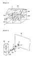
- Figure 3 is a diagram explaining arrangement positions of the devices based on the STs connected to the sockets in the household.
- a house 200 includes, for example, a living room 200A, a room 200B, a room 200C, and a room 200D.
- the living room 200A and the room 200B are arranged on the first floor, and the room 200C and the room 200D are arranged on the second floor.
- the STs are connected to sockets installed on walls. For example, five STs are connected to the sockets installed on the walls of the living room 200A, two STs are connected to the sockets installed on the walls of the room 200B, two STs are connected to the sockets installed on the walls of the room 200C, and two STs are connected to the sockets installed on the walls of the room 200D. In this way, all devices are connected to the power source through the STs.
- FIG 4 is a diagram explaining a connection relationship between the socket connected to the power source and arranged on the wall, the smart tap 11, and the device.
- a refrigerator 201 that is a device includes: a socket 202 including an insertion plug; and wiring 203.
- the socket 202 of the refrigerator 201 is attached to and removed from an output socket 114 of the ST 11.
- a socket 41 is arranged on a wall 40, and commercial power is supplied to an insertion port 411 of the socket 41 through a power system in the household.
- An input socket 113 that is an insertion plug is attached to and removed from the insertion port 411.
- Figure 5 is a floor plan showing a layout of a model house used in an example and a demonstration test of information processing of dynamic priorities described later.
- the model house is a type including one bed room, a living room, and a dining room with a kitchen.
- the numbers described in Figure 5 indicate names of devices shown in Table 1 and locations where the switches of the devices are installed.
- STs described in Figure 5 indicate locations where the smart taps 11 are arranged. Five STs are arranged.
- the ST includes a voltage-current sensor, a semiconductor relay, a ZigBee module, and a microcomputer that controls the entire components and that executes internal processing.
- the microcomputer calculates the power consumption from a current and voltage waveform measured by the voltage-current sensor and specifies the device from a little feature amount indicating features of the voltage and current waveform.
- the data received by the EoD control system of the present invention includes two data: power consumption that is obtained by the ST holding the power consumption calculated at 0.5 second intervals by the microcomputer as data of each period (once/60 seconds) in the internal memory of the smart tap and that is divided into a plurality of packets and transmitted to the server; and a power request message transmitted from the ST when each device 20 requests power.
- the priority apparatus includes a memory with a program storage area and a data storage area.
- the program storage area stores programs, such as a communication processing program, a power use plan setting program, an initial target value update program, and a priority arbitration program.
- the data storage area stores device characteristic class data, message data, and the like.
- Figure 6 is a diagram showing a graph of power consumption of the devices in a house.
- the vertical axis indicates power (W), and the horizontal axis indicates time.
- the graph indicates power consumption at 10 minute intervals in a day. Although the power has been called power consumption so far, a defined term “instantaneous power” will be used below because the meaning is different from general "power consumption”.
- the instantaneous power denotes power consumption obtained by averaging total values of the power consumption added at intervals of minimum control intervals ⁇ (five to ten minutes).
- the power is not used during the day, and the power is used from 8 p.m. to 1 a.m. during which the value of the instantaneous power is high at 1900 W.
- the vertical axis indicates power consumption amount (kWh), and the horizontal axis indicates time.
- the graph indicates a power consumption amount that is an accumulated amount of the instantaneous power at 10 minute intervals in one day, and the value is 10.0 kWh.
- the power consumption amount of a household in Japan is 300 kWh per month and about 10.0 kWh per day, and the power consumption amount of Figure 7 is the same as that of a household per month.
- the accumulated amount of power has been called power consumption amount so far, the meaning of the power consumption amount is different from the normal meaning because the meaning of the instantaneous power is different from the general power consumption.
- a defined term "accumulated power" will be used below.
- upper limits of usable power can include an upper limit of the accumulated power in a certain period (hereinafter, called “ceiling") and an upper limit of the instantaneous power (hereinafter, called “maximum instantaneous power").
- the maximum instantaneous power is provided as an upper limit of the instantaneous power of the power in each time zone to reduce the contract power of the user or to respond to a peak reduction request from a power company to maintain the balance of supply and demand of the power network.
- the ceiling is provided as an upper limit of the accumulated power used in a certain period (such as one day, one week, and one month) to reduce the electric bill or the CO 2 emission of the user.
- the power use pattern of the user can be predicted to set the power use plan by taking the upper limits into account, and the upper limits can be satisfied while maintaining the QoL. Therefore, the power use pattern obtained by predicting the power use pattern of the user and setting the upper limits of the instantaneous value from the pattern and the integrated value will be defined as a "power use plan" and used below.
- the power use plan will be described with a specific example.
- the graphs of Figures 6 and 7 can be estimated to be graphs of a life pattern of a single household, not a life pattern of a household with a married couple and children for example, because the value of the instantaneous power is high at 1900 W in a time period from 8 p.m. to 1 a.m. as shown in the graph of Figure 6 .
- the graph indicated by the instantaneous power of all devices in the household makes a transition in a certain power use pattern.
- the power required by the user in daily life has a unique use pattern, and the QoL can be guaranteed by maintaining the pattern. For example, assuming that the user living in the power use pattern indicated by the graphs of Figures 6 and 7 has made a contract with the power company for 20 A, the breaker trips if the user uses various devices over 2 kW even temporarily, and the electric bill increases with an increase in the power consumption amount of 10.0 kW per day.
- the plan set by reducing the instantaneous power and the accumulated power by 10% based on the power use pattern is the "power use plan”.
- the ceiling in the power use plan is 9.0 kWh, and the maximum instantaneous power is 1.8 kW.
- the upper limits of power include the ceiling in a certain period (upper limit of accumulated power) and the maximum instantaneous power at each timing (upper limit of instantaneous power).
- the amount of power that can be used at each hour needs to be set as a power use plan to satisfy the upper limits.
- the power use pattern of the user can be predicted to set the power use plan based on the pattern by taking the upper limits into account, and the upper limits can be satisfied while maintaining the QoL.
- the power use plan sets the use power of each certain interval ⁇ (ten minutes in the experiment), and this minimum control interval ⁇ will be described.
- the upper limit of the power consumption amount is set to 72 kWh in three days, which is 24 kWh per day, 12 kWh per 12 hours, and 1 kWh per hour.
- the initial target value of the power consumption amount is calculated in multiple stages based on the divided times, and the length used for the control depends on the fineness of the control.
- the time interval of ⁇ will be called a minimum control interval ⁇ , and the user can arbitrarily set the interval within five to ten minute intervals.
- the minimum control interval ⁇ exceeds ten minutes, there are devices that cannot be used when various devices are to be used, because the interval is long.
- the QoL is significantly impaired, and more than ten minutes is not preferable.
- the minimum control interval ⁇ is less than five minutes, the supply power is changed according to the situation changed from moment to moment. Therefore, there can be a situation with unstable supply of power, such as, for example, a situation in which a light bulb flickers because the brightness always changes. Thus, less than five minutes is not preferable.
- Figure 8 is a functional block diagram of a first embodiment showing functions included in the priority apparatus shown in Figure 1 .
- Reference sign 1 of Figure 8 denotes a priority apparatus
- reference sign 10 denotes a memory of the priority apparatus
- reference sign 11 denotes an ST
- the priority apparatus includes initial target value update means 120 and power arbitration means 122.
- Reference sign (1) denotes power consumption transmitted from the ST. Before the operation of the priority apparatus, the priority apparatus executes preprocessing to convert the power consumption to a power use plan for setting the use power at each minimum control interval ⁇ and stores the power use plan, the instantaneous power of the initial target value, and the maximum instantaneous power in the memory 10.
- Reference sign (2) denotes a power request message transmitted from the ST, and the power request message is transmitted to the power arbitration means 122.
- the initial target value update means 120 has a function of allocating a difference between the instantaneous power of the initial target value and the actual instantaneous power to the instantaneous power of a subsequent initial target value to set an updated initial target value and preventing the value from exceeding the maximum instantaneous power.
- the power arbitration means 122 has a function of comparing the updated initial target value and the total value of the power consumption of the device that has transmitted the power request message and the power consumption of the devices in operation, and if the total value is large, selecting a device with a minimum value in the priorities of devices obtained based on electric device characteristic class data described later to select the device according to the characteristics of the device.
- An example of a process executed in advance before the activation of the priority apparatus includes a process of setting the power use plan.
- the setting process of the power use plan will be described below.
- the priority apparatus stores, in the memory, the power consumption transmitted from the ST and calculated at 0.5 second intervals and stores, in the memory, the instantaneous power obtained by averaging the total values of the sums of the power consumption at intervals of the minimum control intervals ⁇ (five to ten minutes).
- a past power use history of the user such as instantaneous power and accumulated power of one week, one month, or each of four seasons, spring, summer, autumn, and winter, is set as a power use plan and stored in the memory.
- the EoD control system of the present invention uses in advance the power use pattern that is the past power use history of the user, makes a power use plan with a target value set by the user, such as a target value of reducing 30%, and determines the ceiling and the maximum instantaneous power to control the power.
- the EoD control system of the present invention uses the ceiling and the maximum instantaneous power to perform the actual control. Therefore, the priority apparatus of the present invention uses in advance the instantaneous power of each time zone based on the past power use history of the user to set the power use plan, and the power use plan can be set in more detail.
- the use power of each device is always transmitted to the priority apparatus, and the priority apparatus accumulates this in the memory.
- the power use plan is set by using the instantaneous power at each minimum control interval ⁇ (ten minutes in the demonstration test described later).
- the ceiling (upper limit accumulated power) set by the user is defined as C(Wh)
- the maximum instantaneous power (upper limit of instantaneous power) is defined as M(t)(W)
- a power demand predicted value at time t is defined as D(t)(W).
- the priority apparatus targets the power of the initial target value T 0 (t)(W) according to the power use plan and controls the devices so that the power falls below the maximum instantaneous power.
- the initial target value T 0 (t)(W) as an example of the power use plan is a plan for reducing a certain proportion of the power use plan at each time to set the initial target values to satisfy the upper limit as a whole (hereinafter, called “certain proportion reduction plan”).
- Figure 9-1 shows an example of this. This is an example for setting the initial target values, and in addition, only the power use peak exceeding the instantaneous power of the power use plan of one day is reduced (hereinafter, called “peak reduction plan”) ( Figure 9-2 ).
- peak reduction plan There is also an example of reducing power according to the power cost (hereinafter, called "cost reduction plan”) ( Figure 9-3 ).
- the cost reduction plan is adopted, and when, for example, the power use in a time period from 1 p.m. to 4 p.m. with the greatest power use is reduced, the power consumption can be reduced by lowering the power cost of the power consumption in the time zone with the highest power cost.
- These reduction plans can set initial target values, and these reduction plans can be combined and set.
- the priority apparatus can select and set a power use plan based on a reduction method necessary for the user.
- the power use plan needs to be set based on the past power use history of the user, and the maximum instantaneous power and the ceiling that are initial target values reduced by the reduction plan selected by the user need to be stored in the memory.
- the initial target value update means 120 described below targets the initial target value to execute a process (interval) of checking the power consumption every certain time ( ⁇ ) and updating the initial target value, and the power arbitration means 122 further executes a process (event driven) of arbitration with other devices according to a request from a device.
- the initial target value update means 120 that executes the process (interval) of updating the initial target value at each minimum control interval ( ⁇ ) based on the initial target value (instantaneous power) will be described.
- the initial target value of power per ⁇ is targeted to perform the control.
- the power cannot be reduced by any means in some cases considering the QoL and the characteristics of devices, and in this case, the actual instantaneous power temporarily exceeds the initial target value.
- the actual instantaneous power may be below the initial target value with a small number of devices used. The devices are obviously used by humans, and the actual instantaneous power also changes depending on the actions at the time. In such a case, the upper limit cannot be ultimately satisfied when the control is continued while the initial target value is maintained.
- Figure 10 is a bar graph showing an example of the actual instantaneous power after the control while the values of the initial target values are maintained.
- the power may not be reduced below the initial target value considering the use status of the device by the user, such as when only a device like an artificial respirator that cannot be stopped exceeds the initial target value at a certain moment.
- the power can temporarily exceed the initial target value within a range not exceeding the maximum instantaneous power, and a subsequent power use plan absorbs the excess in this case to update the initial target value.
- the ceiling can be satisfied by feeding back the difference between the actual instantaneous power and the initial target value to the subsequent initial target value while maintaining the QoL.
- a distribution function for feeding back to the initial target value will be defined. This is for newly calculating the instantaneous power of the initial target value by inputting the difference between the initial target value and the actual instantaneous power and distributing the difference to the initial target value at a time after the time at which the difference is generated.
- Figure 11 is an explanatory view when the control of feeding back the difference between the actual instantaneous power and the initial target value to the subsequent plan values is performed.
- the priority apparatus updates the power use plan.
- a power use plan T i (t) indicates a power use plan after updates of i times, that is, at time t after a lapse of i ⁇ .
- ⁇ is a distribution function for updating the power use plan, and the different between the instantaneous power of the initial target value and the actual instantaneous power is distributed to subsequent instantaneous power. Therefore, the difference is input to Expression (5) to determine the power of the difference to be distributed to subsequent instantaneous power.
- T 1 (t noW ) is a current initial plan value
- E(t noW ) is current use power
- a method of uniformly distributing the difference to all of the subsequent new initial target values (hereinafter, called “uniform distribution method of difference”) is performed.
- the difference can be distributed only to the immediately following instantaneous power (hereinafter, called “instantaneous power distribution method”).
- the method of distributing the difference includes the method of uniform distribution of difference and instantaneous power distribution.
- the power arbitration means 122 for providing priorities between devices to execute the process (event driven) of arbitration with other devices according to a request from a device while maintaining the QoL will be described.
- a power request from a device is generated at a timing that the user wants to use the device, and the request is made independently of ⁇ described above. Although some requests can be held for five to ten minutes of the minimum control interval ⁇ , other requests immediately require power. For such a device, the power is not supplied in time when the control is performed at each ⁇ , and the QoL is reduced. Therefore, the power used to execute the arbitration process with other devices in response to a power request of a device is not the instantaneous power, but the actual power consumption. In this way, the power requests generated at various timings can be immediately handled, and whether to shift the time can be immediately determined.
- the EoD control system needs indicators for determining to which devices the power will be supplied when individual devices request power. To satisfy the upper limit, not all devices can receive desired power, and necessary devices vary depending on the devices and the situation of the user. Therefore, there is a problem of determining to which devices the power will be preferentially supplied. Thus, the priorities need to be set according to the characteristics of the devices and the situation. Therefore, functions of priority with values of 0 to 1 are set for the devices, and the power is preferentially supplied to devices with large values of priority. The QoL is satisfied by using the devices after the supply of power. Therefore, the cost reduction and the social contribution through energy saving are not taken into account.
- the characteristics of the devices need to be recognized in advance because the method of controlling the power varies between devices.
- a parameter indicating the characteristics of the power requested by each device and the power control method will be called QoEn.
- the devices are classified based on the following power control method of devices.
- the devices are combined by the three types of power control method, and the devices are classified into eight types of classes as shown in Table 2.
- the data classified into eight types of classes will be defined and used as "electric device characteristic class data".
- the electric device characteristic class data is used to control the priorities between devices.
- the eight types of classes are associated with the device names indicated by identification ID shown in the fields of appliances to determine the devices to be prioritized by using the priorities of the devices in use. For example, when the priority apparatus receives a power request message from an ST, the priority apparatus uses the priorities of devices and the electric device characteristic class data among the device that has transmitted the message and the devices in operation to determine whether to permit or refuse the message.
- the devices classified into (1) adjustable devices are devices that can use the functions of the devices even if the supplied power is reduced in some degree when the devices are used, and examples of the devices include a drier and a light bulb.
- devices of (2) request power, there is no problem in terms of functions of the devices without immediate supply of power if the power is to be supplied before a certain time, and examples of the devices include a rice cooker and a washing machine. Even if the power supply is interrupted when devices of (3) are used, the interruption only slightly affects the life of the user using the devices, and examples of the devices include an air conditioner and a refrigerator.
- Devices such as an artificial respirator, for securing safe and comfortable life are classified into class 8.
- the devices classified into the eight types of classes are not fixed to the classes shown in Table 2.
- the user can arbitrarily determine the classes of the devices. For example, if a bedridden elderly selects an air conditioner as a device that is always necessary, the air conditioner is classified into class 8.
- the electric devices that cannot be classified into the adjustable, interruptible, and time-shiftable classes include a security and monitoring device such as a gas detector, a medical device such as an artificial respirator, and a network device such as a router.
- An example of the power-adjustable devices includes a drier.
- the satisfaction of the user is the highest when the requested power is supplied, and the satisfaction does not significantly change even if the supply power is reduced in some degree as shown in Figure 12 .
- the capacity of the device is limited when the power is significantly reduced, and the satisfaction of the user is reduced.
- the priority for the minimum required power is high, and the priority for supplying power as requested is low.
- the priorities for the supply power can be provided by such a monotonically decreasing function.
- the power arbitration means defines priorities Pri a adj (p) of the power-adjustable devices as in the following expression, wherein p req a denotes request power of a device a, and p min a denotes minimum required power.
- Pri a adj p ⁇ 0 if p a req ⁇ p 1 - p a req - p p a req - p a min ⁇ a adj if p a min ⁇ p ⁇ p a req 1 if p ⁇ p a min
- time-shiftable devices at activation includes a rice cooker. These are devices for which the activation time can be delayed as long as the operation of the devices is completed before designated time. Therefore, as shown in Figure 13 , the priority is low just after the request of power, and the priority increases with a decrease in the time before the device must be activated.
- the devices can be defined in this way.
- Priorities Pri shift a (t) of the time-shiftable devices a are defined as in the following expression, wherein t req a denotes request time, and t must a denotes time that the device must be activated.
- Pri a shift t ⁇ 1 - t - t a req t a must - t a req ⁇ a a shift if t ⁇ t a must 1 if t > t a must ,
- the interruptible devices includes an air conditioner.
- the interruptible device is a device that runs toward a steady state during operation as in the temperature setting of the air conditioner and that can maintain the steady state once the device reaches the steady state even if the operation is suspended.
- a high priority needs to be provided to run toward the steady state just after the start of the operation, and the priority can be reduced when the device reaches the steady state because the steady state is maintained even after an interruption. After the interruption, the device gets out of the steady state with time, and the priority needs to be raised to restart the device.
- Priorities Pri int a (t) of the interruptible devices can be defined and divided into a case in which a is in operation and a case in which a is suspended as in the following expressions.
- Pri a int t ⁇ Pri a run t a in operation
- Pri a run t ⁇ t - t a enable t a stop - t a enable a a run if t ⁇ t a enable 1 otherwise
- Pri a sus t ⁇ t - t a sus t a must - t a sus a a sus if t ⁇ t a must 1 otherwise
- the classes of general devices are defined by combinations of three characteristics shown in Table 2.
- Priority functions of the classes are defined as shown in the items of Table 3 based on combinations of the priorities defined for the characteristics.
- Figure 15 is a diagram explaining a processing procedure by the priority apparatus supplying power based on the priorities in response to a power request message.
- the user can set the maximum available electric energy (ceiling) to realize the power reduction as much as the user wants.
- a device a req that needs power transmits a power request message (Table 4) to a server (1 of Figure 15 ).
- the server that has received the request immediately compares a sum E' total (t noW ) of total use power E total (t noW ) at current time t noW and request power E req with a power use plan T i (t noW ). If the entire power (sum) E' total (t noW ) is below the plan, the requested power E req is permitted (Expression (14)). If a req ⁇ A Wait , the request is refused (2' of Figure 15 ).
- the priority of each device is calculated, and the power of another device with a lower priority than the device a req is reduced (3 of Figure 15 ) in an interruption process (Expression (15)).
- the power is secured, and the total use power E total (t noW ) is updated to determine the reduction in the power supply according to the characteristics of the device.
- a message provided with information described in Table 4 such as available power E supply is immediately transmitted to the device a req , and the device uses power according to the message.
- the devices for which the power supply is refused or interrupted and a req determine power use policies again in the next interval process (4 of Figure 15 ).
- the priority apparatus that has received requests from the devices compares the sum E' total (t noW ) of the total use power E total (t noW ) in operation at the current time t noW and the request power E req with the power use plan T i (t noW ). If the sum E' total (t noW ) exceeds the power use plan T i (t noW ), the power of a device a min with the minimum priority is reduced according to Expression (15), and the priority is updated.
- Data of fields of values and fields of required classes is associated with items of device identification ID, request power, minimum activation power, interruptible time, and required activation time shown in fields of items in Table 4.
- the ST transmits the data of the values and the required classes to the priority apparatus.
- Data of fields of values is associated with device identification ID, type of message, permitted average power, and permitted use time shown in fields of items of Table 5.
- the priority apparatus transmits the data to the ST.
- Item Value Device identification ID ID Type of message Permit/refuse Permitted average power E supply (W) Permitted use time Time
- the above-described dynamic priority control means 1 including the initial target value update means 120 and the power arbitration means 122 can save power by reducing the accumulated power and can avoid a massive blackout at the peak, because the instantaneous power does not exceed the upper limit, and the accumulated power does not exceed the target value C.
- the priority apparatus 1 can ultimately control the instantaneous power equal to or below the maximum instantaneous power and can control the power to satisfy the target value C of the accumulated power.
- the instantaneous power can be controlled by the instantaneous power equal to or below the maximum instantaneous power and can control the power to satisfy the target value C of the accumulated power.
- the power may exceed the maximum instantaneous power.
- a second embodiment for handling such a case will be described.
- Figure 16 is a functional block diagram explaining functions included in a multiple power source management apparatus
- Figure 17 is a functional block diagram of the second embodiment.
- the priority apparatus includes the initial target value update means 120, priority arbitration means 123, and constant monitoring means 124.
- the initial target value update means 120 and the priority arbitration means 123 have the same functions as the means described above, and the description will not be repeated.
- the constant monitoring means 124 constantly monitors the power consumption, and when the entire power consumption exceeds the maximum instantaneous power for equal to or longer than a certain period d (about 0.5 to 2 seconds), the priority arbitration means 123 performs arbitration based on the priorities without waiting for a lapse of ⁇ , so that the entire power consumption falls below the maximum instantaneous power.
- the former immediately makes a determination in response to the power request transmitted from a device when, for example, the switch is turned on and maintains the QoL by not inhibiting the use of the device.
- the latter is performed for continued requests from the devices, and an update of plan values and arbitration between devices are performed. If the supply power is always changed according to the situation that changes from moment to moment, there can be a situation with unstable operation of devices, such as, for example, a situation in which a light bulb flickers because the brightness always changes. Therefore, the minimum control interval ⁇ is implemented to attain the stabilization as a whole.
- the maximum instantaneous power is further secured by always monitoring the power so that the power does not exceed the maximum instantaneous power.
- Figure 18 is an overall flow chart showing preprocessing by the CPU of the priority apparatus before the activation of the priority apparatus.
- a process of setting initial target values of a power use plan and storing the initial target values in the memory is executed as preprocessing in step S 1.
- FIG 19 is a flow chart showing entire processing of the CPU after the activation of the CPU of the priority apparatus. After the activation, the CPU of the priority apparatus executes an update process of the initial target values in step S3 and executes an arbitration process of the priorities in step S5.
- Figure 20 is a flow chart of the power use plan setting process of step S 1 described above.
- the CPU adds and averages the power consumption of one day, one week, one month, or the like transmitted from the ST of each device at intervals of the minimum control intervals ⁇ , such as 10 minute intervals, to convert the power consumption to instantaneous power and accumulated power in step S11.
- step S 13 an initial target value T 0 (t)(W) as an example of the power use plan is created from Expressions (17) and (18), wherein the ceiling (upper limit of accumulated power) set by the user from the instantaneous power and the accumulated power is C(Wh), the maximum instantaneous power (upper limit of instantaneous power) is M(W), and the power demand predicted value at the time t is D(t)(W).
- D ⁇ t ⁇ D t if D t ⁇ M M t otherwise
- T 0 t C ⁇ t start t end ⁇ D ⁇ t ⁇ D ⁇ t
- the initial target value T 0 (t)(W) is stored in the memory in the preprocessing before the activation.
- Examples of other power use plans include the peak reduction plan for reducing only the power use peak exceeding the instantaneous power of the power use plan of one day ( Figure 9-2 ) and the cost reduction plan for reducing the power according to the power cost ( Figure 9-3 ).
- the initial target value can be set by these reduction plans, and these reduction plans can be combined to set the initial target value.
- Figure 21 is a flow chart of the initial target value update process of step S3 described above.
- the CPU calculates distribution power by a distribution method of difference (uniform distribution method of difference or instantaneous power distribution method) from the difference between the instantaneous power of the initial target value and the actual instantaneous power and adds the distribution power to the instantaneous power of the subsequent initial target value to calculate an updated initial target value in step S31.
- the updated initial target value and the maximum instantaneous power are compared in step S33, and if it is determined Yes in S35, the instantaneous power of the subsequent initial target value is updated with the updated initial target value in step S37. If it is determined No, the initial target value is updated with the maximum instantaneous power to set the updated initial target value in step S39.
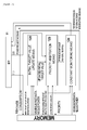
- FIGs 22-1 to 22-4 are flow charts of the priority arbitration process of step S5 described above.
- the CPU when the CPU receives a power request message from an ST in step S51, the CPU calls up the power consumption of the device that has transmitted the power request message and the power consumption of the devices in operation from the memory at the time of the reception of the power request message and adds the power consumptions to obtain a total value in step S53.
- step S55 the priorities of the devices are calculated based on the priority functions with reference to Table 3, and the values are stored in the memory.
- step S56 power source load factors of power sources are calculated and stored in the memory based on the power source load factor functions and the supply power of the commercial power source as well as power sources including storage batteries if necessary.
- step S57 the device with the minimum priority and the power source with the maximum power source load factor are selected from the memory.
- step S59 a permission message is transmitted to the ST of the device that has transmitted the message in the following step, and the process ends. If it is determined No in step S59, the process proceeds to step S65 of (1).
- step S65 whether the device is adjustable is determined with reference to Table 2 in step S65. If it is determined Yes in step S67, an interruption message for lowering the power is transmitted to the device in step S69, and the supply power equivalent to the power reduction is reduced from the power source in step S70. In step S71, the priority of the device and the power source load factor of the power source are recalculated based on the power consumption and the supply power after the reduction, and the process returns to step S56.
- step S73 whether the device is the ST that has transmitted the request message and is time-shiftable is determined in step S73. If it is determined Yes in step S75, a refusal message is transmitted to the ST of the device in step S77, and the supply power equivalent to the power reduction is reduced from the power source in step S78. The priority of the appliance and the power source load factor of the power source are recalculated based on the power consumption and the supply power after the reduction in step S79, and the process returns to step S56. If it is determined No in step S75, the process proceeds to step S81 of (3). As shown in Figure 22-4 , whether the device is not the ST that has transmitted the request message and is interruptible is determined in step S81.
- step S83 a refusal message is transmitted to the ST of the device in step S85, and the supply power equivalent to the power reduction is reduced from the power source in step S86.
- the priority of the appliance and the power source load factor of the power source are recalculated based on the power consumption and the supply power after the reduction in step S87, and the process returns to step S56. If it is determined No in step S83, the process ends.
- FIGS 23-1 to 23-3 are flow charts of the constant monitoring process.
- the CPU calls up the maximum instantaneous power from the memory in step S91 and calls up and adds the power consumptions of the devices in operation from the memory every certain period ⁇ (0.5 to 2 seconds) to obtain the total value of the power consumption in step S93.
- the priority of the device is calculated based on the priority function with reference to Table 3, and the value is stored in the memory.
- the total value of the power consumption and the maximum instantaneous power are compared in step S97, and the process ends if it is determined that the total value of the power consumption is small in step S99. If it is determined that the total value of the power consumption is large in step S99, the priorities are called up from the memory to select the device with the minimum value in step S101. The process proceeds to (4).
- step S103 whether the device is adjustable is determined with reference to the priority class data of Table 2 in step S103. If the determination is Yes in step S105, an interruption message for lowering the power is transmitted to the device in step S107. The total value of the power consumption is updated based on the lowered power in step S109, and the process returns to step S99. This is repeated until the total value of the power consumption is smaller than the maximum instantaneous power. If the determination is No, the process proceeds to (5).
- step S111 whether the device is interruptible is determined in step S111. If the determination is Yes in step S113, a refusal message is transmitted to the ST of the device in step S 115. The power consumption of the device is excluded to update the total value of the power consumption in step S117, and the process returns to step S99. This is repeated until the total value of the power consumption is smaller than the maximum instantaneous power.
- the power arbitration means of the priority apparatus controls the power supply to the electric device so that the power supply is always below the maximum instantaneous power.
- the priority apparatus targets all devices installed in the household and the office.
- the power does not exceed the ceiling and the upper limit of the maximum instantaneous power even if devices of three types of characteristics are not installed, or for example, even if adjustable devices are not installed.
- the use power of each device is always transmitted to the priority apparatus.
- the priority apparatus accumulates this in the memory and integrates the accumulated use power of each device to obtain the accumulated power of a certain period (one day, one week, one month, or the like).
- the power arbitration means controls the power supply to the electric devices so that the power supply is always below the maximum instantaneous power, and as a result, the power does not exceed the upper limit (ceiling) of the accumulated power.
- a storage battery for example is added as necessary to the commercial power source to extend the power source to a plurality of power sources, and "power source QoEn” is defined as characteristic description for the arbitration of the power sources.
- the power source QoEn of the commercial power source and the storage battery is defined as in Table 6.
- the maximum instantaneous power and the ceiling of the commercial power source are the upper limit of the instantaneous power and the upper limit of the accumulated power used in the conventional EoD control system, and the user can arbitrarily set them.
- the electric bill, the CO 2 emission factor, and the like of each time are set based on the power contract.
- a maximum value of power that can be supplied from the storage battery (maximum discharge power), a maximum value of power that can be charged in the storage battery (maximum charge power), and electric energy that can be charged in the storage battery (storage capacity) are defined.
- the supply from the storage battery is expressed by a positive number
- the charge in the storage battery is expressed by a negative number. Since a loss or self-discharge occurs at the charge and discharge, charge efficiency, discharge efficiency, and self-discharge power that are factors indicating charge-discharge efficiency are defined.
- Power source load factors (LF: also called load factors) of the power sources correspond to dynamic priorities of the devices and are functions indicating supply capacities of the power sources according to the situation. This will be described in detail later.
- the storage battery is added to extend the power source to a plurality of power sources, and the power supply plans of the individual power sources are created at the same time.
- the power use plan without the use of the storage battery is set as an initial plan, and the storage battery is used from there to minimize the dissatisfaction indicating the inconvenience of the user to create a power supply plan using the storage battery.
- the appliance group is defined as A, each appliance is defined as a ⁇ A, and a predicted power consumption pattern PD_a(t) of each appliance is learned in advance.
- the commercial power source is defined as c
- the storage battery is defined as b
- the power supply pattern of each power source is defined as PS s (t) (wherein s ⁇ [c, b]).
- PS s (t) (wherein s ⁇ [c, b]).
- the total supply power and the total power consumption always coincide as in the following expression due to physical restrictions.
- PS b (t)>0 discharge
- PS b (t) ⁇ 0 charge from the commercial power source.
- Accumulated supply power ES c (t) of the commercial power source and storage amount ES b (t) of the storage battery are defined as follows.
- ⁇ b and ⁇ b ' indicate charge-discharge efficiencies, wherein 0 ⁇ b 1 and 0 ⁇ b ' ⁇ 1.
- Expressions (20) to (22) are expressed by an integral to be exact, the average power of each unit time segment (20 seconds in the experiment) is used here as a power value, and the expressions are expressed by a sum instead of an integral.
- the maximum instantaneous power is expressed by PS c t ⁇
- the ceiling of the accumulated power is expressed by ES c ⁇ as restrictions for the power feed from the commercial power source set by the user.
- the maximum discharge power is expressed by PS b ⁇
- the maximum charge power is expressed by - PS b ⁇
- the storage capacity is expressed by ES b ⁇ as characteristics of the storage battery.
- the supply power of each power source needs to satisfy the following restrictions.
- T indicates a period of creating the plan, such as one day and one week, and this will be called a plan period in the present research.
- the storage battery is not taken into account, and a power use plan when only the commercial power is used is created as an initial value.
- an initial power use plan PD PLAN t that is an initial power use plan satisfying the maximum instantaneous power and the ceiling of the commercial power source is created as in the following Expression (25)
- PD PLAN t ES c ⁇ ⁇ D ⁇ t ⁇ D ⁇ t
- the use power at the peak is cut so that the power does not exceed the maximum instantaneous power PS C t ⁇ , and a certain proportion is reduced from the predicted demand in each time zone so that the accumulated power does not exceed the ceiling ES C ⁇ .
- the use power is cut at the peak of demand to reduce the power consumption of the device below the maximum instantaneous power of the commercial power source.
- the use power at the peak is cut to always satisfy the maximum instantaneous power PS C t ⁇ .
- the peak of power demand is a time zone that the consumer needs the power most, and the limitation of the power that can be used in this time zone significantly reduces the comfort of the user's life.
- the storage battery system of the present invention defines the dissatisfaction DS PD PLAN at the power use as follows and shifts the time of the supply power through the charge and discharge of the storage battery to minimize the dissatisfaction to solve the problem of significantly reducing the comfort.
- the dissatisfaction function is defined by the following expression.
- the dissatisfaction function is designed so that the value is larger when the power is largely reduced in the same time zone, compared to when the power is reduced little by little in the entire plan period.
- the storage battery is used to modify the initial power use plan to minimize the dissatisfaction, and the power supply plan of each power source PS c PLAN t , PS b PLAN t is created.
- the dissatisfaction minimization problem can be solved by using the storage battery as in Figure 24 to shift the time of the power consumption.
- the power use plan is modified, and the power feed plan of the commercial power source and the charge-discharge plan of the storage battery are created.
- the following shows a specific calculation algorithm.
- T DST t
- T SRC ⁇ t
- Step 3 if the dissatisfaction of the charge source and the discharge destination satisfies ds D t SRC , PD PLAN t SRC ⁇ ds D t DST , PD PLAN t DST , Step 3. is executed. If not, Step 5. is executed.
- charge-discharge power C is a maximum value satisfying the following expressions.
- the charge-discharge power C is obtained as follows.
- the maximum C satisfying Expression (37) is provided by the following expression.
- C ⁇ 1 ⁇ b ⁇ ⁇ b + 1 ⁇ D t DST - PD PLAN t DST - D t SRC - PD PLAN t SRC
- C SRC max PS b t SRC - PS b ⁇
- C DST max PS b ⁇ - PS b t DST ⁇ b ⁇ ⁇ b
- the maximum C satisfying Expression (36) is provided by the following expression.
- C ⁇ ⁇ C SRC max if C ⁇ > C SRC max ⁇ C DST max > C SRC max C DST max if C ⁇ > C DST max ⁇ C SRC max > C DST max C ⁇ otherwise
- ⁇ indicates the length of the time segment. If C>0, the plan is modified to charge and discharge electricity by C as follows.
- PD PLAN t SRC and PS b PLAN t SRC are reduced by C. More specifically, this means that in the time segment t SRC , the storage battery is discharged by C without changing PS c PLAN t SRC (see Expression (32)).
- PS b PLAN t SRC : PS b PLAN t SRC - C
- PD PLAN t SRC : PD PLAN t SRC - C
- the maximum value max ⁇ ES b PLAN t of the storage plan obtained by this algorithm indicates the minimum storage capacity of the target customer.
- Positive and negative maximum gradients in the charge-discharge plan PS b PLAN t calculated by the algorithm indicates the required maximum charge-discharge power of the storage battery, and the specifications of the storage battery necessary for the customer can be designed from these values.
- the appliances that receive the supply power and the amount of the supply power are arbitrated based on the priorities of the appliances.
- the EoD corresponding to multiple power sources proposed in the present research from which power source the power will be supplied also needs to be arbitrated at the same time.
- the power source load factor is implemented as an indicator indicating how much load is imposed on each power source based on the characteristics and the state of each power source.
- the power source load factor is defined as in the following expression as a function for the supply power from the power source.
- the supply power is the commercial power in (a) of Figure 25
- the supply power is the storage battery in (b) of Figure 25 .
- LF S p ⁇ 1 if p > PS S 2 ⁇ ⁇ tan - 1 ⁇ ⁇ S ⁇ p - J 2 ES S ⁇ - ES S t if PS S ⁇ ⁇ p ⁇ PS S ⁇ - 1 if p ⁇ PS S ⁇
- ⁇ s is a setting parameter for determining the inclination of the function.
- the power source load factor is 0 when the supply power coincides with the target power Ts, and the power source load factor is greater when the supply power is greater than the target power. Therefore, the spare energy of power that can be supplied is greater in a power source with a smaller power source load factor, and this indicates that the power can be preferentially supplied to a new power request.
- the power source load factor defined here is used for the arbitration of the power request of the appliance. The power is supplied if the priority of the request power from the appliance is higher than the power source load factor, and the request with a priority lower than the power source load factor is rejected.
- the present method using the power source load factor can realize flexible arbitration of supplying power according to the spare energy of the power source as long as the priority of the power request is high even if the power exceeds the target value.
- the inclination of the power source load factor function indicates how strictly the target value is maintained.
- the inclination becomes steeper when the accumulated supply power ES s t of the power sources approaches the upper limit ES s ⁇ , , and the target value is designed to be more strictly maintained.
- the power source load factor is a negative value when the supply power is equal to or smaller than the target value, and the power is supplied for the power request with the priority equal to or smaller than 0 only when the supply power is equal to or smaller than the target value.
- ⁇ a ⁇ A PD a REQ ⁇ a ⁇ A PS s RES , ⁇ a ⁇ A , ⁇ s ⁇ S : Pri a PD a REQ ⁇ LF S PS S REQ
- PD a REQ and Pri a PD a REQ indicate the power allocated to the appliance a and the priority of the appliance a, respectively
- PS S REQ indicates the supply power from the power source s.
- Expression (50) indicates a physical restriction that the total use power and the total supply power coincide
- Expression (51) indicates that power is supplied only for the power request with the priority equal to or greater than the power source load factor.
- a method of extending three real-time arbitration processes in the EoD system to the arbitration of multiple power sources will be described. Basically, (1) the arbitration is performed in an event drive process every time a power request message is received, and (2) the gap between the plan and the power use history is fed back in a periodic activation process. Furthermore, (3) the total power consumption is monitored in a constant monitoring process to prevent the total from exceeding the maximum instantaneous power.
- the processes will be described in detail.
- An object of the event drive process is to determine whether the power can be supplied in response to a power request message transmitted from an appliance according to the target power Ts of the power source.
- a change in the operation mode associated with a large power fluctuation such as ON/OFF of the switch of an appliance and high and low of a drier, is handled as an event of the appliance, and a power request message is issued at this timing.
- a specific power source and appliance arbitration algorithm will be described below based on Figure 26 .
- An appliance a min ⁇ A with the minimum priority, and a power source S max with the maximum power source load factor are selected.
- a min arg min a ⁇ A Pri a PS a REQ
- s max arg max s ⁇ S LF s PS s RES ,
- the supply power to a min is reduced according to the capability of the appliance a min (power request is time-shifted / operating appliance is interrupted / allocation power is reduced).
- the reduced power supply to a min is PD a min NEXT , , and the supply power of s max and the request power of a min are updated as follows.
- PS s max RES : PS s max RES - PD a min REQ - PD a min NEXT
- PD a max REQ : PD a max NEXT
- the arbitration is performed while transmitting the power allocation message of power reduction, interruption, or the like to the appliance.
- the time-shifted or interrupted appliance can again issue a power request message with a higher priority after a lapse of a certain time to perform arbitration to receive power allocation when there is spare energy in the supply power or when the priority is higher than the power source load factor.
- the power arbitration is performed based on the power use plan and the power supply plan created in advance based on the predicted power use pattern.
- the actual action pattern of the consumer varies from day to day, and the pattern cannot completely coincide with the plan.
- T s PS S PLAN t in the initial state according to the supply plan.
- the object value is updated as in the following expressions based on the actual value of the supply power.
- t now T plays a role of a feedback gain, which is larger in the later stage of the plan period.
- the correction is performed to more strictly follow the plan.
- ES t t indicates accumulated power supplied by the power source until the time
- ES t PLAN indicates an accumulated amount until the time of the power supply plan.
- t T is the feedback gain. The feedback gain increases toward the end time, and the feedback gain is controlled to more quickly approach the plan value.
- Expression (51) may not be satisfied with respect to the target value Ts.
- the appliance and power source arbitration described in (1) is performed again.
- the power is not used more than the allocation power at the arbitration, there is a margin in the power, and the power can be allocated to the appliance in which the power is reduced or to the suspended or time-shifted appliance.
- such an appliance issues a request again every certain time and is arbitrated as described in (1). Therefore, the rearbitration is not particularly required in the periodic activation process.
- the storage battery can be controlled to always maintain the allocated power in the present invention, and the commercial power source absorbs the power fluctuation not associated with the power request. Consequently, the supply power of the commercial power source may exceed the maximum instantaneous power PS c ⁇ due to the power fluctuation. Therefore, the supply power of the commercial power source is always monitored in the constant monitoring process, and the same arbitration as in (1) is performed to reduce the power when the power is about to exceed the maximum instantaneous power. As indicated in Expression (49), if the supply power exceeds the maximum instantaneous power PS c ⁇ , the power source load factor is 1, which is the maximum value. Therefore, the power of the appliances is to be reduced in the ascending order of priority until the supply power to the appliance with any priority is equal to or smaller than the maximum instantaneous power.
- a power consumption pattern of the actual life in the smart apartment is used as a predicted use power pattern used to create a power use plan and as power request data for real-time arbitration.
- the smart apartment is for one or two people including one living room, one dining room with a kitchen, one bed room, one toilet, and one bathroom.
- FIG. 27 Nineteen types of appliances shown in Figure 27 are installed in the smart apartment.
- the smart taps are attached to all appliances, and the power consumption of each appliance can be measured and collected every 0.5 seconds. Data of one day, 24-hour life of a single subject and data of life of a married couple are used as real data.
- the time of the use of each appliance and the operation mode are detected from the real life data, and the power is requested from the same appliance at the same time in the real-time arbitration.
- the use time (time for requesting power) is extended so that the accumulated power during operation is the same for an appliance, such as a pot, in which the use time becomes long in order to fulfill a certain function if the power is reduced.
- the use time does not change even if the power is reduced or suspended.
- Figure 27 shows the appliances used in the experiment and the controllability of the appliances.
- a pot, a coffee maker, a rice cooker, and a dish washer are appliances that request power to attain certain accumulated power
- the other appliances are appliances that request power to attain certain request time.
- the power to be allocated can be reduced from the request power in the arbitration, and the priority increases with an increase in the reduction of power.
- the time-shiftable appliances can wait for the allocation of power for a certain time after the power request, and the priority increases with an increase in the length of the waiting time.
- the interruptible appliances are appliances that can be suspended by the arbitration during operation, and the priority increases with an increase in the length of the suspended time.
- Results of creation of power use plans and power supply plans are compared with the conventional EoD control system. In this case, restrictions of the commercial power source are set.
- the maximum instantaneous power of a couple 1000 ⁇ W
- the ceiling ES c ⁇ of the accumulated power is obtained by reducing the power consumption 15%.
- Figure 28 shows the created power use plans. Lines with highest values in Figure 28 indicate the predicted power consumption D(t). Lines with lowest values from around noon to night are power use plans created by the conventional EoD that does not use the storage battery. Lines with intermediate values around noon and lowest values from dawn to morning indicate power use plans according to the present invention.
- Figure 29 shows charge-discharge plans of the storage battery in this case.
- the power use plans are significantly reduced in time zones in which the predicted power consumption exceeds the maximum instantaneous power.
- the storage battery is charged in a time segment with a small power request in the present invention, and the power is discharged in a time zone with a large power request. Therefore, the amount of reduction is small, and the power use plans are close to the predicted power consumption, thereby reducing the dissatisfaction.
- Figure 30 shows power (storage plans) charged in the storage battery in this case. It can be recognized from the maximum values of the storage plans that the storage capacity necessary for the life pattern of a single is about 300 Wh, and even for a couple, 411.2 Wh is sufficient.
- an optimal storage battery is designed for the power consumption pattern to determine the optimal capacity of the storage battery.
- the maximum charge-discharge power of the storage battery is determined.
- the charge-discharge power can be determined from the maximum value (maximum discharge power) and the minimum value (maximum charge power) of the power supply plan (charge-discharge plan) of the storage battery.
- the power use plan and the supply plan are created based on the average power at each ⁇ , and the peak power generated at intervals equal to or smaller than ⁇ is averaged and becomes small. Therefore, the power use plan value and the power supply plan value of the commercial power are distributed at each ⁇ according to the ratio of the size of the predicted demand in the time ⁇ , and the difference between the values is set as charge-discharge power. The values are distributed so that the commercial power does not exceed the maximum instantaneous power.
- Figure 29 shows the maximum discharge power (positive number) and the maximum charge power (negative number) at each ⁇ of the storage battery in the case shown in Figure 28 .
- lines with high values indicate the predicted demand, and lines with low values indicate the charge-discharge plans.
- a simulation experiment of arbitration for an actual power request is conducted for a couple.
- data obtained by moving up, by two hours, the power consumption pattern of the actual life used to create the plan is used.
- the maximum instantaneous power and the ceiling in this case are the same as the conditions described above, and the plans illustrated above are also used for the power use plan and the supply plan.
- Figure 31 shows arbitration results of the storage battery system of the present invention
- Figure 32 shows arbitration results of the conventional EoD control system.
- Lines with high power values in Figures 31 and 32 indicate request power
- lines with low power values indicate power used as a result of arbitration
- intermediate lines indicate power use plans.
- the maximum instantaneous power of the commercial power source is changed in increments of 20 W in a range of 300 ⁇ W ⁇ PS c t ⁇ ⁇ 1500 ⁇ W to create a plan and to simulate arbitration.
- Figure 33 shows results of checking dissatisfaction DS (PD), in which the value of the maximum instantaneous power of the commercial power source is changed, and power fluctuation of the commercial power source based on the flattening factor (Flattening Factor) in order to evaluate the effectiveness of the peak cut by evaluating how much power is supplied with respect to the power request based on the value of dissatisfaction.
- PD dissatisfaction DS
- Flattening Factor flattening factor
- the flattening factor is evaluated by the following Expression (59) as a ratio of average power with respect to the maximum power.
- FF 1 T ⁇ t T PS c t max t ⁇ T ⁇ PS c t
- Figure 33(a) shows results of the conventional EoD control system
- Figure 33(b) shows results of the present invention using the storage battery.
- the conventional EoD control system when the maximum instantaneous power falls below 840 W, the dissatisfaction indicated by the above line rapidly increases. The flattening factor is reduced, and the maximum instantaneous power from the commercial power source is reduced.
- Figure 34 shows arbitration results when the maximum instantaneous power in the conventional EoD system is 860 W and 840 W.
- the reason that the flattening factors in the conventional EoD system are significantly reduced at the same time is that the coffee maker continues to wait, and the priority is increased.
- other appliances with lower priorities cannot be used, and the overall average power is significantly reduced.
- arbitration results for a power request are also compared in the case of a single.
- data obtained by moving up, by two hours, the power consumption pattern of the actual life used to create the plan is used for the power request in this case.
- the maximum instantaneous power and the ceiling in this case are the same as in the conditions described above, and the plans illustrated above are also used for the power use plan and the supply plan.
- Figure 35 shows arbitration results of the storage battery system of the present invention
- Figure 36 shows arbitration results of the conventional EoD control system.
- lines with high power values indicate request power
- lines with low power values indicate power used as a result of arbitration
- intermediate lines indicate power use plans.
- the change in the dissatisfaction when the value of the maximum instantaneous power for the commercial power source is changed is checked in order to show the effectiveness of the storage battery for the peak cut.
- the maximum instantaneous power of the commercial power source is changed in increments of 20 W in a range of 300 ⁇ W ⁇ PS c t ⁇ ⁇ 1500 ⁇ W to create a plan and to simulate arbitration.
- Figure 37 shows results of checking dissatisfaction DS (PD), in which the value of the maximum instantaneous power of the commercial power source is changed, and power fluctuation of the commercial power source based on the flattening factor (Flattening Factor) in order to evaluate the effectiveness of the peak cut by evaluating how much power is supplied with respect to the power request based on the value of dissatisfaction.
- PD dissatisfaction DS
- Flattening Factor flattening factor
- the flattening factor is evaluated by the following Expression (60) as a ratio of average power with respect to the maximum power.
- FF 1 T ⁇ t T PS c t max t ⁇ T ⁇ PS c t
- Figure 37(a) shows results of the conventional EoD control system
- Figure 37(b) shows results of the present invention using the storage battery.
- the dissatisfaction indicated by an upper line rapidly increases when the maximum instantaneous power falls below 780 W and 400 W in the conventional EoD system.
- the flattening factor slightly decreases, but does not significantly change, and the maximum instantaneous power from the commercial power source is not significantly reduced.
- the dissatisfaction hardly changes in the present invention using the storage battery, and particularly, the dissatisfaction when the maximum instantaneous power of the commercial power source is small is about the same as when the maximum instantaneous power is large. It can be recognized that the flattening factor increases with a decrease in the maximum instantaneous power.
- the on-demand power control is not performed, the maximum instantaneous power supplied from the commercial power source (system power source) is 700 W, and the sum of the instantaneous power supplied from the commercial power source and the instantaneous power supplied from the storage battery is 1500 W at the maximum.
- the capacity of the storage battery necessary for these conditions is obtained.
- the storage battery with the obtained capacity is used along with the commercial power source to supply power to appliances installed in rooms of a couple.
- Figure 38 shows the results.
- a line with highest values at about 12 o'clock and 21 o'clock among three lines shows a transition of predicted use power.
- a line that is flat at dawn, from 11 o'clock to 17 o'clock, and around 21 o'clock shows a transition of power supplied from the commercial power source.
- a line that is the lowest at dawn and that is flat up to about 11 o'clock shows power based on charge and discharge of the storage battery.
- Figure 39 shows a notion for obtaining the capacity of the storage battery necessary for the transition of the instantaneous power shown in Figure 38 . It can be understood in Figure 39 that the power charged in the morning is discharged with the subsequent increase in the required instantaneous power, and the power is temporarily completely discharged at 15 o'clock. The capacity necessary for the storage battery can be reduced if the power is not completely discharged. However, the capacity of the storage battery in which the power is temporarily completely discharged is the minimum capacity necessary for the storage battery.
- the minimum capacity necessary for the storage battery is 1812 Wh in this example.
- the on-demand power control is not performed, the storage battery capacity is 411.2 Wh, and the sum of the instantaneous power supplied from the commercial power source and the instantaneous power supplied from the storage battery is 1500 W at the maximum. Under these conditions, the power is optimized to minimize the peak power.
- the storage battery capacity is the capacity obtained based on the example of Figure 30 .
- the storage battery with the capacity is used along with the commercial power source to supply power to appliances installed in rooms of a couple.
- Figure 40 shows the results.
- a line indicating the highest value at about 12 o'clock among three lines indicates a transition of predicted use power.
- a line that has high values after 1 o'clock in the night and that is flat at around 12 o'clock indicates a transition of power supplied from the commercial power source.
- the predicted use power and the commercial power source make a transition at the same instantaneous power.
- a line that is lowest at about 0 o'clock in the night and that is flat up to about 11 o'clock with a small peak around 12 o'clock shows power based on the charge and discharge of the storage battery.
- the peak of the instantaneous power supplied from the commercial power source requires 1104 W, which is higher power than the result of Comparative Example 1.
- Figure 41 shows a transition of the charge amount of the storage battery used in the example shown in Figure 40 .
- the power charged in the morning is discharged with an increase in the instantaneous power at around 12 o'clock.
- the discharge is completely finished at about 13 o'clock, and power is not charged until after 0 o'clock in the night.
- the capacity of the storage battery is clearly insufficient, and the discharge is possible only in a short time around noon.
- the on-demand power control is not performed, the storage battery capacity is changed by 10 Wh from 10 Wh to 4000 Wh, and the maximum instantaneous power at each storage battery capacity is optimized and obtained to minimize the peak power.
- the power is optimized to minimize the peak power.
- Figure 42 shows the results.
- the storage battery system of the present invention can control power sources according to various life patterns by extending the EoD control system to multiple power sources including a storage battery.
- the storage battery capacity can be appropriately designed, and an appropriate charge-discharge management system can be formed.
- Examples of the multiple power sources include a commercial power source and power sources (solar power, gas power, and the like) other than the storage battery, and extension to an electric vehicle is possible.
Landscapes
- Engineering & Computer Science (AREA)
- Business, Economics & Management (AREA)
- Human Resources & Organizations (AREA)
- Economics (AREA)
- Strategic Management (AREA)
- General Physics & Mathematics (AREA)
- Physics & Mathematics (AREA)
- Power Engineering (AREA)
- Entrepreneurship & Innovation (AREA)
- Tourism & Hospitality (AREA)
- Marketing (AREA)
- General Business, Economics & Management (AREA)
- Theoretical Computer Science (AREA)
- Development Economics (AREA)
- Quality & Reliability (AREA)
- Operations Research (AREA)
- Health & Medical Sciences (AREA)
- Game Theory and Decision Science (AREA)
- Water Supply & Treatment (AREA)
- Public Health (AREA)
- General Health & Medical Sciences (AREA)
- Primary Health Care (AREA)
- Educational Administration (AREA)
- Automation & Control Theory (AREA)
- General Engineering & Computer Science (AREA)
- Supply And Distribution Of Alternating Current (AREA)
- Remote Monitoring And Control Of Power-Distribution Networks (AREA)
- Management, Administration, Business Operations System, And Electronic Commerce (AREA)
Applications Claiming Priority (2)
| Application Number | Priority Date | Filing Date | Title |
|---|---|---|---|
| JP2012158109 | 2012-07-13 | ||
| PCT/JP2013/067927 WO2014010442A1 (fr) | 2012-07-13 | 2013-06-28 | Système de gestion de multiples sources de puissance à la demande, programme de système de gestion de multiples sources de puissance à la demande et support d'enregistrement lisible par ordinateur sur lequel ledit programme est enregistré |
Publications (2)
| Publication Number | Publication Date |
|---|---|
| EP2874264A1 true EP2874264A1 (fr) | 2015-05-20 |
| EP2874264A4 EP2874264A4 (fr) | 2016-03-30 |
Family
ID=49915906
Family Applications (1)
| Application Number | Title | Priority Date | Filing Date |
|---|---|---|---|
| EP13817253.1A Withdrawn EP2874264A4 (fr) | 2012-07-13 | 2013-06-28 | Système de gestion de multiples sources de puissance à la demande, programme de système de gestion de multiples sources de puissance à la demande et support d'enregistrement lisible par ordinateur sur lequel ledit programme est enregistré |
Country Status (8)
| Country | Link |
|---|---|
| US (1) | US20150214768A1 (fr) |
| EP (1) | EP2874264A4 (fr) |
| JP (2) | JPWO2014010442A1 (fr) |
| KR (1) | KR20150043311A (fr) |
| CN (1) | CN104662763A (fr) |
| SG (1) | SG11201500172TA (fr) |
| TW (1) | TWI520460B (fr) |
| WO (1) | WO2014010442A1 (fr) |
Cited By (6)
| Publication number | Priority date | Publication date | Assignee | Title |
|---|---|---|---|---|
| WO2016040929A1 (fr) * | 2014-09-12 | 2016-03-17 | Sunculture Solar Inc. | Génération, distribution d'énergie solaire, et système de communication |
| US9444397B2 (en) | 2012-10-26 | 2016-09-13 | Sunculture Solar, Inc. | Integrated solar panel |
| US9620993B2 (en) | 2012-10-26 | 2017-04-11 | Solpad, Inc. | Auto-synchronous isolated inlet power converter |
| EP3118962A4 (fr) * | 2014-03-12 | 2017-11-01 | Nec Corporation | Système de partage de batterie d'accumulateurs, dispositif de traitement d'informations, procédé de partage de batterie d'accumulateurs, et programme de partage de batterie d'accumulateurs d'enregistrement de support d'enregistrement |
| US9948139B2 (en) | 2012-10-26 | 2018-04-17 | Solpad, Inc. | Solar power generation, distribution, and communication system |
| CN108364082A (zh) * | 2018-02-11 | 2018-08-03 | 北京车和家信息技术有限公司 | 一种电动车辆换电方法及相关设备 |
Families Citing this family (33)
| Publication number | Priority date | Publication date | Assignee | Title |
|---|---|---|---|---|
| WO2015087470A1 (fr) * | 2013-12-10 | 2015-06-18 | パナソニックIpマネジメント株式会社 | Dispositif et programme de prédiction de la demande |
| US10050799B2 (en) | 2014-01-28 | 2018-08-14 | Patched Conics, LLC. | Power control system and method, and information communication ability control system and method |
| JPWO2015129734A1 (ja) * | 2014-02-25 | 2017-03-30 | 住友電気工業株式会社 | エネルギー管理システム、エネルギー管理方法及びコンピュータプログラム |
| JP6593325B2 (ja) * | 2014-03-31 | 2019-10-23 | 日本電気株式会社 | 監視装置、監視システム、監視方法及びプログラム |
| JP6168528B2 (ja) * | 2014-07-28 | 2017-07-26 | 国立研究開発法人宇宙航空研究開発機構 | 電力制御システム、方法、及び、情報伝達能力制御システム、方法 |
| WO2016189976A1 (fr) * | 2015-05-25 | 2016-12-01 | 富士電機株式会社 | Dispositif d'alimentation sans coupure et son procédé de commande |
| JP6109254B2 (ja) * | 2015-07-10 | 2017-04-05 | 三菱電機株式会社 | 機器制御装置及び機器制御プログラム |
| CN105957263B (zh) * | 2016-06-17 | 2019-01-25 | 浙江右边数字科技有限公司 | 车载终端、充电桩、电动自行车以及其租用系统及方法 |
| CN106655200B (zh) * | 2016-09-13 | 2018-12-25 | 浙江大学 | 一种空调聚合提供电力系统运行备用响应量的计算方法 |
| CN118659338A (zh) | 2016-09-15 | 2024-09-17 | 萨万特系统公司 | 用于创建动态纳电网和用于聚集电功率消耗方以参与能量市场的系统和方法 |
| US10707683B2 (en) * | 2016-09-29 | 2020-07-07 | Tokitae Llc | Directing or modulating electrical power drawn by one or more loads from a solar photovoltaic module array while maintaining a buffer margin |
| CN106549448A (zh) * | 2016-12-06 | 2017-03-29 | 林鹏 | 电动汽车内置电池的外部接口连接装置 |
| JP6725406B2 (ja) * | 2016-12-12 | 2020-07-15 | 株式会社東芝 | 発電計画策定装置、発電計画策定方法、および発電計画策定プログラム |
| CN107222257B (zh) * | 2017-06-07 | 2019-12-17 | 国网江苏省电力公司南京供电公司 | 一种测量配用电通道质量的方法和装置 |
| US20210247727A1 (en) * | 2018-04-22 | 2021-08-12 | Nova Lumos Ltd. | A system and method for providing power to authenticated devices connected to a renewable energy source power unit |
| EP3821685B1 (fr) * | 2018-07-10 | 2022-03-09 | Signify Holding B.V. | Dispositif d'éclairage et système d'éclairage |
| CN108879953A (zh) * | 2018-07-11 | 2018-11-23 | 久能峰润(长春)科技有限公司 | 一种虚拟调峰发电厂系统及其智能硬件控制设备 |
| JP7245080B2 (ja) * | 2019-03-11 | 2023-03-23 | 東京瓦斯株式会社 | 推奨容量提示システム、推奨容量提示方法及びプログラム |
| KR102242446B1 (ko) * | 2019-03-18 | 2021-04-20 | 이엔테크놀로지 주식회사 | 전력시스템의 동작 중에 제약 코드의 자동화된 수정이 가능한 전력관리장치 및 전력시스템 |
| JP7240295B2 (ja) * | 2019-09-25 | 2023-03-15 | 株式会社日立製作所 | 地域エネルギー管理装置及び地域エネルギー管理方法 |
| KR102606576B1 (ko) * | 2019-10-24 | 2023-11-27 | 삼성중공업(주) | 선박 에너지 관리 시스템 및 방법 |
| KR20210074919A (ko) * | 2019-12-12 | 2021-06-22 | 삼성전자주식회사 | 서버 및 이의 제어 방법 |
| CN118605327A (zh) * | 2020-02-07 | 2024-09-06 | 大连富士冰山智控系统有限公司 | 控制系统和控制方法 |
| KR102377126B1 (ko) * | 2020-02-18 | 2022-03-22 | 충북대학교 산학협력단 | 수요 불확실성 감소를 위한 요구전력 기반 ess 전력분배 시스템 |
| KR102414200B1 (ko) * | 2020-02-20 | 2022-06-27 | 충북대학교 산학협력단 | ESS의 SoC 부하 최소화를 위해 시프트된 전력을 재공급하는 전력 제어 시스템 |
| US20210263578A1 (en) * | 2020-02-24 | 2021-08-26 | Massachusetts Institute Of Technology | Photovoltaic smart power distribution box and controller |
| WO2021178205A1 (fr) | 2020-03-03 | 2021-09-10 | Massachusetts Institute Of Technology | Capteur de capacité de réseau photovoltaïque |
| TWI798703B (zh) * | 2021-05-21 | 2023-04-11 | 鄭宇竣 | 智慧節能系統 |
| US11424641B1 (en) | 2021-06-09 | 2022-08-23 | Savant Systems, Inc. | Flexible load management system |
| US11941228B2 (en) | 2021-08-31 | 2024-03-26 | Savant Systems, Inc. | Guidance set-up for companion module graphical display |
| US11621580B2 (en) | 2021-08-31 | 2023-04-04 | Savant Systems, Inc. | Microgrid switchover using zero-cross detection |
| CN115375151B (zh) * | 2022-08-25 | 2023-07-11 | 合肥未来计算机技术开发有限公司 | 一种井下施工的作业人员安全调度方法 |
| CN115891879B (zh) * | 2022-11-29 | 2024-05-14 | 重庆长安汽车股份有限公司 | 整车下电后的供电方法及装置 |
Family Cites Families (19)
| Publication number | Priority date | Publication date | Assignee | Title |
|---|---|---|---|---|
| JP3621853B2 (ja) * | 1999-09-17 | 2005-02-16 | 株式会社日立製作所 | 電力供給システム |
| JP2001255967A (ja) * | 2000-03-13 | 2001-09-21 | Toshiba Corp | 情報処理装置及びその電力制御方法 |
| US6832135B2 (en) * | 2001-07-10 | 2004-12-14 | Yingco Electronic Inc. | System for remotely controlling energy distribution at local sites |
| US7561977B2 (en) * | 2002-06-13 | 2009-07-14 | Whirlpool Corporation | Total home energy management system |
| US20070222295A1 (en) * | 2002-09-05 | 2007-09-27 | Paul Wareham | System and method for power load management |
| DE10347684B4 (de) * | 2002-10-15 | 2015-05-07 | Denso Corporation | Verfahren und Vorrichtung zum Betreiben und zur Steuerung von Verbrauchern auf einem Fahrzeug |
| JP4325467B2 (ja) * | 2004-03-31 | 2009-09-02 | 日本電気株式会社 | 自動電源制御システム |
| JP4864809B2 (ja) * | 2007-05-17 | 2012-02-01 | 日本電信電話株式会社 | 機器制御装置、機器制御システムおよび機器制御方法 |
| US8334771B2 (en) | 2007-06-13 | 2012-12-18 | National Institute Of Information And Communications Technology | Home network, area network using the same, program for computer to execute operation in home network, and computer-readable recording medium storing the program |
| US20090063228A1 (en) * | 2007-08-28 | 2009-03-05 | Forbes Jr Joseph W | Method and apparatus for providing a virtual electric utility |
| US7715951B2 (en) * | 2007-08-28 | 2010-05-11 | Consert, Inc. | System and method for managing consumption of power supplied by an electric utility |
| CN102341991B (zh) * | 2009-01-06 | 2014-04-16 | 松下电器产业株式会社 | 电力控制系统和电力控制系统的控制方法以及程序 |
| US8054598B1 (en) * | 2009-01-16 | 2011-11-08 | Exaflop Llc | Negotiating capacity allocation among distributed current protection devices |
| JP5424161B2 (ja) | 2009-02-16 | 2014-02-26 | 独立行政法人情報通信研究機構 | 需給調停システム、需給調停装置、需給調停方法および需給調停プログラム |
| JP4703736B2 (ja) * | 2009-03-02 | 2011-06-15 | 株式会社東芝 | エネルギー管理システム及び方法 |
| CN101800439B (zh) * | 2009-12-23 | 2012-05-23 | 刘瑜 | 家用电器的用电管理装置 |
| JP2011154495A (ja) | 2010-01-27 | 2011-08-11 | Nec System Technologies Ltd | 文字コード変換装置、文字コード変換方法、および文字コード変換プログラム |
| JP5436396B2 (ja) * | 2010-11-01 | 2014-03-05 | 三菱電機株式会社 | 電力制御装置、電力制御システム、電力制御プログラム、及び電力制御方法 |
| JP5628021B2 (ja) * | 2010-12-21 | 2014-11-19 | パナソニック株式会社 | 電気機器制御装置、電気機器制御方法及び電気機器 |
-
2013
- 2013-06-28 JP JP2014524737A patent/JPWO2014010442A1/ja active Pending
- 2013-06-28 KR KR20157003349A patent/KR20150043311A/ko not_active Application Discontinuation
- 2013-06-28 CN CN201380037509.7A patent/CN104662763A/zh active Pending
- 2013-06-28 EP EP13817253.1A patent/EP2874264A4/fr not_active Withdrawn
- 2013-06-28 US US14/414,317 patent/US20150214768A1/en not_active Abandoned
- 2013-06-28 SG SG11201500172TA patent/SG11201500172TA/en unknown
- 2013-06-28 WO PCT/JP2013/067927 patent/WO2014010442A1/fr active Application Filing
- 2013-06-28 TW TW102123397A patent/TWI520460B/zh not_active IP Right Cessation
-
2015
- 2015-10-13 JP JP2015202272A patent/JP2016041005A/ja active Pending
Cited By (6)
| Publication number | Priority date | Publication date | Assignee | Title |
|---|---|---|---|---|
| US9444397B2 (en) | 2012-10-26 | 2016-09-13 | Sunculture Solar, Inc. | Integrated solar panel |
| US9620993B2 (en) | 2012-10-26 | 2017-04-11 | Solpad, Inc. | Auto-synchronous isolated inlet power converter |
| US9948139B2 (en) | 2012-10-26 | 2018-04-17 | Solpad, Inc. | Solar power generation, distribution, and communication system |
| EP3118962A4 (fr) * | 2014-03-12 | 2017-11-01 | Nec Corporation | Système de partage de batterie d'accumulateurs, dispositif de traitement d'informations, procédé de partage de batterie d'accumulateurs, et programme de partage de batterie d'accumulateurs d'enregistrement de support d'enregistrement |
| WO2016040929A1 (fr) * | 2014-09-12 | 2016-03-17 | Sunculture Solar Inc. | Génération, distribution d'énergie solaire, et système de communication |
| CN108364082A (zh) * | 2018-02-11 | 2018-08-03 | 北京车和家信息技术有限公司 | 一种电动车辆换电方法及相关设备 |
Also Published As
| Publication number | Publication date |
|---|---|
| TW201409890A (zh) | 2014-03-01 |
| WO2014010442A1 (fr) | 2014-01-16 |
| EP2874264A4 (fr) | 2016-03-30 |
| US20150214768A1 (en) | 2015-07-30 |
| JP2016041005A (ja) | 2016-03-24 |
| SG11201500172TA (en) | 2015-07-30 |
| TWI520460B (zh) | 2016-02-01 |
| CN104662763A (zh) | 2015-05-27 |
| KR20150043311A (ko) | 2015-04-22 |
| JPWO2014010442A1 (ja) | 2016-06-23 |
Similar Documents
| Publication | Publication Date | Title |
|---|---|---|
| EP2874264A1 (fr) | Système de gestion de multiples sources de puissance à la demande, programme de système de gestion de multiples sources de puissance à la demande et support d'enregistrement lisible par ordinateur sur lequel ledit programme est enregistré | |
| TWI497429B (zh) | 隨選型電力控制系統、隨選型電力控制系統程式及記錄其程式之電腦可讀取記錄媒體 | |
| KR101662415B1 (ko) | 온디맨드형 전력 제어 시스템, 온디맨드형 전력 제어 시스템 프로그램 및 그 프로그램을 기록한 컴퓨터 판독 가능한 기록 매체 | |
| KR102336642B1 (ko) | 온도 조절 방법 및 장치 | |
| JP5856666B2 (ja) | 電力需給制御装置及び電力需給制御方法 | |
| JP6249895B2 (ja) | 電力制御システム、方法及び電力制御装置 | |
| EP3389162A1 (fr) | Dispositif régulateur d'énergie, procédé d'élaboration de plans d'exploitation, et programme | |
| Özkan | A new real time home power management system | |
| US20100023786A1 (en) | System and method for reduction of electricity production and demand | |
| JP6403875B2 (ja) | 機器管理装置、機器管理システム、機器管理方法及びプログラム | |
| US20160241033A1 (en) | Control device, control method, and program | |
| US10186864B2 (en) | Method of controlling the electrical regulation of an electrical installation as a function of curtailment settings | |
| JP5410637B6 (ja) | オンデマンド型電力制御システム、オンデマンド型電力制御システムプログラム及びそのプログラムを記録したコンピュータ読み取り可能な記録媒体 | |
| US20240241158A1 (en) | Self-produced energy surplus/shortage information generation device, self-produced energy surplus/shortage information generation method, photovoltaic system, microgrid energy supply and demand system, and microgrid energy supply and demand method | |
| WO2023119725A1 (fr) | Dispositif de génération d'informations de surplus/pénurie d'énergie privée, procédé de génération d'informations de surplus/de pénurie d'énergie privée, système de génération d'énergie solaire, système d'alimentation et de demande d'énergie de micro-réseau, et procédé d'alimentation et de demande d'énergie de micro-réseau | |
| Javaid et al. | Adaptive Control of Energy Storage Systems for Real-Time Power Mediation Based on Energy on Demand System. Designs 2022, 6, 97 |
Legal Events
| Date | Code | Title | Description |
|---|---|---|---|
| PUAI | Public reference made under article 153(3) epc to a published international application that has entered the european phase |
Free format text: ORIGINAL CODE: 0009012 |
|
| 17P | Request for examination filed |
Effective date: 20150213 |
|
| AK | Designated contracting states |
Kind code of ref document: A1 Designated state(s): AL AT BE BG CH CY CZ DE DK EE ES FI FR GB GR HR HU IE IS IT LI LT LU LV MC MK MT NL NO PL PT RO RS SE SI SK SM TR |
|
| AX | Request for extension of the european patent |
Extension state: BA ME |
|
| RAP1 | Party data changed (applicant data changed or rights of an application transferred) |
Owner name: NITTO DENKO CORPORATION Owner name: KOZO KEIKAKU ENGINEERING INC. |
|
| DAX | Request for extension of the european patent (deleted) | ||
| RA4 | Supplementary search report drawn up and despatched (corrected) |
Effective date: 20160302 |
|
| RIC1 | Information provided on ipc code assigned before grant |
Ipc: H02J 13/00 20060101ALI20160225BHEP Ipc: G06Q 10/00 20120101ALI20160225BHEP Ipc: H02J 3/00 20060101AFI20160225BHEP Ipc: G06Q 50/06 20120101ALI20160225BHEP |
|
| 17Q | First examination report despatched |
Effective date: 20170120 |
|
| STAA | Information on the status of an ep patent application or granted ep patent |
Free format text: STATUS: THE APPLICATION IS DEEMED TO BE WITHDRAWN |
|
| 18D | Application deemed to be withdrawn |
Effective date: 20170531 |