EP2874167B1 - Junction box and contactor device - Google Patents
Junction box and contactor device Download PDFInfo
- Publication number
- EP2874167B1 EP2874167B1 EP12880874.8A EP12880874A EP2874167B1 EP 2874167 B1 EP2874167 B1 EP 2874167B1 EP 12880874 A EP12880874 A EP 12880874A EP 2874167 B1 EP2874167 B1 EP 2874167B1
- Authority
- EP
- European Patent Office
- Prior art keywords
- extension part
- extension
- connection end
- junction box
- connection
- Prior art date
- Legal status (The legal status is an assumption and is not a legal conclusion. Google has not performed a legal analysis and makes no representation as to the accuracy of the status listed.)
- Active
Links
- 238000009434 installation Methods 0.000 claims description 62
- 238000005452 bending Methods 0.000 claims description 18
- 230000000149 penetrating effect Effects 0.000 claims description 3
- 238000003466 welding Methods 0.000 claims description 3
- 238000010586 diagram Methods 0.000 description 15
- 230000011218 segmentation Effects 0.000 description 2
- 230000009286 beneficial effect Effects 0.000 description 1
- 239000003990 capacitor Substances 0.000 description 1
Images


Classifications
-
- H—ELECTRICITY
- H02—GENERATION; CONVERSION OR DISTRIBUTION OF ELECTRIC POWER
- H02G—INSTALLATION OF ELECTRIC CABLES OR LINES, OR OF COMBINED OPTICAL AND ELECTRIC CABLES OR LINES
- H02G15/00—Cable fittings
- H02G15/02—Cable terminations
-
- H—ELECTRICITY
- H01—ELECTRIC ELEMENTS
- H01H—ELECTRIC SWITCHES; RELAYS; SELECTORS; EMERGENCY PROTECTIVE DEVICES
- H01H50/00—Details of electromagnetic relays
- H01H50/02—Bases; Casings; Covers
- H01H50/021—Bases; Casings; Covers structurally combining a relay and an electronic component, e.g. varistor, RC circuit
-
- H—ELECTRICITY
- H01—ELECTRIC ELEMENTS
- H01H—ELECTRIC SWITCHES; RELAYS; SELECTORS; EMERGENCY PROTECTIVE DEVICES
- H01H50/00—Details of electromagnetic relays
- H01H50/02—Bases; Casings; Covers
- H01H50/04—Mounting complete relay or separate parts of relay on a base or inside a case
- H01H50/041—Details concerning assembly of relays
- H01H50/045—Details particular to contactors
-
- H—ELECTRICITY
- H01—ELECTRIC ELEMENTS
- H01H—ELECTRIC SWITCHES; RELAYS; SELECTORS; EMERGENCY PROTECTIVE DEVICES
- H01H50/00—Details of electromagnetic relays
- H01H50/14—Terminal arrangements
-
- H—ELECTRICITY
- H01—ELECTRIC ELEMENTS
- H01H—ELECTRIC SWITCHES; RELAYS; SELECTORS; EMERGENCY PROTECTIVE DEVICES
- H01H50/00—Details of electromagnetic relays
- H01H50/54—Contact arrangements
- H01H50/541—Auxiliary contact devices
- H01H50/543—Auxiliary switch inserting resistor during closure of contactor
-
- H—ELECTRICITY
- H01—ELECTRIC ELEMENTS
- H01H—ELECTRIC SWITCHES; RELAYS; SELECTORS; EMERGENCY PROTECTIVE DEVICES
- H01H71/00—Details of the protective switches or relays covered by groups H01H73/00 - H01H83/00
- H01H71/08—Terminals; Connections
-
- H—ELECTRICITY
- H01—ELECTRIC ELEMENTS
- H01R—ELECTRICALLY-CONDUCTIVE CONNECTIONS; STRUCTURAL ASSOCIATIONS OF A PLURALITY OF MUTUALLY-INSULATED ELECTRICAL CONNECTING ELEMENTS; COUPLING DEVICES; CURRENT COLLECTORS
- H01R4/00—Electrically-conductive connections between two or more conductive members in direct contact, i.e. touching one another; Means for effecting or maintaining such contact; Electrically-conductive connections having two or more spaced connecting locations for conductors and using contact members penetrating insulation
- H01R4/28—Clamped connections, spring connections
- H01R4/30—Clamped connections, spring connections utilising a screw or nut clamping member
- H01R4/36—Conductive members located under tip of screw
- H01R4/363—Conductive members located under tip of screw with intermediate part between tip and conductive member
-
- H—ELECTRICITY
- H02—GENERATION; CONVERSION OR DISTRIBUTION OF ELECTRIC POWER
- H02G—INSTALLATION OF ELECTRIC CABLES OR LINES, OR OF COMBINED OPTICAL AND ELECTRIC CABLES OR LINES
- H02G3/00—Installations of electric cables or lines or protective tubing therefor in or on buildings, equivalent structures or vehicles
- H02G3/02—Details
- H02G3/08—Distribution boxes; Connection or junction boxes
- H02G3/081—Bases, casings or covers
- H02G3/083—Inlets
-
- H—ELECTRICITY
- H02—GENERATION; CONVERSION OR DISTRIBUTION OF ELECTRIC POWER
- H02G—INSTALLATION OF ELECTRIC CABLES OR LINES, OR OF COMBINED OPTICAL AND ELECTRIC CABLES OR LINES
- H02G3/00—Installations of electric cables or lines or protective tubing therefor in or on buildings, equivalent structures or vehicles
- H02G3/02—Details
- H02G3/08—Distribution boxes; Connection or junction boxes
- H02G3/18—Distribution boxes; Connection or junction boxes providing line outlets
Definitions
- the present invention relates to a junction box, particularly to a junction box with a feeder function, and a contactor device using the junction box.
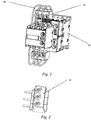
- Figs. 1-3 are schematic structural diagrams of a combination of a junction box 10 and a contactor 20 in the prior art. As shown in Figs. 1-3 , a resistance wire 30 lies over the junction box 10, which neither is advantageous for fastening and installing the junction box 10, nor facilitates the connection and installation of a cable 40.
- German Patent DE 197 29 595 C1 is directed to a capacitor switching contactor which includes a standard contactor, an auxiliary switch, an input terminal block, as well as resistance wires disposed between the terminal blocks and the auxiliary switch.
- the resistance wires are connected to connecting terminals in chambers of the terminal blocks, and largely accommodated in the housing of the terminal blocks.
- the technical problem to be solved by the present invention is to provide a junction box which is simple to install.
- the present invention is solved by a junction box having the features of claim 1.
- an electrical junction box which includes a casing, a first installation space, a second installation space, and a connection part arranged in the case body;
- the connection part includes a main body, a first connection end, and a second connection end;
- the main body is used for connecting to a cable;
- the first connection end is connected to the main body, is located in the first installation space, and is used for connecting to a contactor;
- the second connection end is arranged on the first connection end and is located in the second installation space.
- the main body is located on one side of the junction box, and the first connection end and the second connection end are located on the other, opposite side of the junction box.
- an installation hole is formed inside the main body, and the installation hole is used for accommodating the cable.
- the first connection end comprises a first extension part, a second extension part, a third extension part, and a fourth extension part;
- the first extension part extends into the installation hole and is connected to the main body;
- the second extension part is formed by bending and extending from the first extension part and is perpendicular to the first extension part;
- the third extension part is formed by bending and extending from the second extension part, and the third extension part is perpendicular to the second extension portion and parallel to the first extension part;
- the fourth extension part is formed by bending and extending from the third extension part and is parallel to the third extension part.
- the second connection end is arranged on the first connection end; the second connection end comprises a first extension structure, a second extension structure, and a third extension structure; the first extension structure is perpendicularly arranged on the third extension part and extends from the third extension part; the second extension structure is bent from the first extension structure until it is opposite to the third extension part and parallel to the third extension part; the third extension structure perpendicularly extends from the second extension structure; and when the connection part is assembled to the casing, the third extension structure extends into the second installation space, and is used for connecting to a resistance wire.
- the casing comprises a first layer and a second layer arranged above the first layer; the first layer comprises a plurality of first installation spaces arranged at intervals; and the second layer comprises a plurality of second installation spaces arranged at intervals.
- the second installation spaces correspond to the first installation spaces in a one to one manner.
- connection holes used for installing the resistance wires are also formed on the second layer; the connection holes are in communication with the second installation spaces after penetrating the top of the second layer; and the connection holes correspond to the second installation spaces in a one to one manner.
- the first connection end comprises a first extension part, a second extension part, a third extension part, and a fourth extension part;
- the first extension part is connected to the main body;
- the second extension part is formed by bending and extending from the first extension part and is perpendicular to the first extension part;
- the third extension part is formed by bending and extending from the second extension part, and the third extension part is perpendicular to the second extension portion and is parallel to the first extension part;
- the fourth extension part is formed by bending and extending from the third extension part and is parallel to the third extension part.
- the second connection end comprises a first extension structure, a second extension structure, and a third extension structure;
- the first extension structure is perpendicularly arranged on the third extension part;
- the second extension structure is bent from the first extension structure until it is opposite to the third extension part and parallel to the third extension part;
- the third extension structure perpendicularly extends from the second extension structure along a direction parallel to the third extension part; and when the connection part is assembled to the casing, the third extension structure extends into the second installation space, and is connected to the resistance wire inserted into the connection hole.
- first connection end is assembled with the second connection end by welding or riveting.
- the second installation spaces correspond to the first installation spaces in a one to one manner.
- the present invention further provides a contactor device, comprising a contactor, a resistance wire, and a cable; the contactor further comprises the above-mentioned junction box; the first connection end is connected to the contactor; the resistance wire is connected to the second connection end; the main body is connected to the cable; a joint between the first connection end and the contactor, and a joint between the resistance wire and the second connection end are located on one side of the junction box; and a joint between the main body and the cable is located on the other, opposite side of the junction box.
- the joint between the resistance wire and the second connection end is located between the joint between the first connection end and the contactor and the joint between the main body and the cable.
- the contactor device and the junction box thereof in the present invention comprise a first connection end and a second connection end, wherein the first connection end may be used for connecting to a contactor, while the second connection end may be used for connecting to a resistance wire; in this way, the resistance wire may be connected to the second connection end without passing over the junction box, which is not only advantageous to fasten and install the junction box, but also facilitates the connection and installation of the cable.
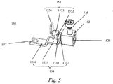
- Fig. 4 is a schematic diagram of a junction box 100 in an embodiment of the present invention.
- the junction box 100 comprises a casing 120 and a connection part 150.
- the connection part 150 is arranged in the casing 120, and can be connected to other elements.
- the casing 120 may be a hollow structure which is roughly a cuboid.
- the casing 120 comprises a first wall 122 such as a top wall (when the junction box 100 is at the location as shown in Fig. 4 ), a second wall 125 opposite to the first wall 122 and arranged at an interval such as a bottom wall (when the junction box 100 is at the location as shown in Fig. 4 ), two side walls 126 located between the first wall 122 and the second wall 125 and respectively connecting the first wall 122 and the second wall 125 on two sides, and a segmentation structure 128.
- the first wall 122, the second wall 125 and the two side walls 126 6 enclose an internal space; the segmentation structure 128 is arranged in the internal space enclosed by the first wall 122, the second wall 125 and the two side walls 126, and segment the internal space into a plurality of first installation spaces 1282.
- a protruding part 1223 is arranged at one end of the first wall 122, such as the left end (when the junction box 100 is at the location shown in Fig. 4 ).
- the protruding part 1223 is roughly perpendicular to the second wall 125 and extends along a direction away from the second wall 125 so that an outer surface of the first wall 122 is in a step shape.
- a second installation space 1225 is arranged on the protruding part 1223, and the second installation space 1225 is in communication with a corresponding first installation space 1282 for installing the connection part 150.
- the connection part 150 comprises a main body 152, a first connection end 153, a second connection end 155 and a bolt terminal 156, wherein the main body 152 may be arranged in the casing 120; an installation hole 1523 is formed inside of the main body 152; and the installation hole 1523 is used for accommodating a cable 40 (as shown in Fig. 6 ).
- the bolt terminal 156 passes through the first wall 122 and the main body 152, and is connected to the cable 40 which is located in the installation hole 1523.
- a first end of the first connection end 153 is connected to the main body 152, and a second end of the first connection end 153 bends and extends from the first end of the first connection end 153 so as to connect to a contactor 20.
- the first connection end 153 comprises a first extension part 1532, a second extension part 1533, a third extension part 1535 and a fourth extension part 1536.
- the first extension part 1532 extends into the installation hole 1523 and is connected to the main body 152.
- the second extension part 1533 is formed by bending and extending downwards from the first extension part 1532 (when the first connection end 153 is at the location shown in Fig. 5 ) and is roughly perpendicular to the first extension part 1532.
- the third extension part 1535 is formed by bending and extending to the left from the second extension part 1533 (when the first connection end 153 is at the location shown in Fig. 5 ), and the third extension part 1535 is roughly perpendicular to the second extension part 1533 and is roughly parallel to the first extension part 1532.
- the fourth extension part 1536 is formed by bending and extending downwards from the third extension part 1535 and is roughly perpendicular to the third extension part 1535.
- the particular shapes of the first extension part 1532, the second extension part 1533, the third extension part 1535 and the fourth extension part 1536 may be adjusted according to the particular shapes, etc. of the first installation space 1282 so as to install the first connection end 153 in the corresponding first installation space 1282.
- a gap 1537 may be further arranged on an edge of the fourth extension part 1536.
- a second connection end 155 is arranged on the first connection end 153.
- the second connection end 155 comprises a first extension structure 1552, a second extension structure 1553, and a third extension structure 1556.
- the first extension structure 1552 is arranged roughly perpendicular to one side of the third extension part 1535, and extends upwards from the third extension part 1535 (when the first connection end 153 is at the location shown in Fig. 5 ).
- the second extension structure 1553 bends from the first extension structure 1552 until it is opposite to the third extension part 1535 and roughly parallel to the third extension part 1553.
- the third extension structure 1556 extends upwards roughly perpendicularly from one side of the second extension structure 1553; and as shown in Fig. 4 , when the connection part 150 is assembled to the casing 120, the third extension structure 1556 extends into the second installation space 1225 for connecting to the resistance wire 30 (as shown in Fig. 6 ).
- junction box 100 in an embodiment of the present invention
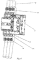
- the contactor device shown in Fig. 6 is taken as an example for briefly describing the connection relationships of the junction box 100 with the contactor 20, the resistance wire 30 and the cable 40.
- the junction box 100 may be connected to the contactor 20 by means of the first connection end 153.
- the third extension structure 1556 of the second connection end 155 is located between the bolt terminal 156 and the contactor 20, i.e., with respect to the bolt terminal 156, the third extension structure 1556 of the second connection end 155 is closer to the contactor 20.
- the main body 152 is located on one side of the junction box 100, while the first connection end 153 and the second connection end 155 are located on the other, opposite side of the junction box 100; or that is to say, a joint between the first connection end 153 and the contactor 20 as well as a joint between the resistance wire 30 and the second connection end 155 are located on one side of the junction box 100, while a joint between the main body 152 and the cable 40 is located on the other, opposite side of the junction box 100; or that is to say, the joint between the resistance wire 30 and the second connection end 155 is located between the joint between the first connection end 153 and the contactor 20 and the joint between the main body 152 and the cable 40.
- the resistance wire 30 is connected to the third extension structure 1556 of the second connection end 155 on one side of the junction box 100, while the cable 40 is connected to the bolt terminal 156 on the other side of the junction box 100, that is, the resistance wire 30 may be connected to the third extension structure 1556 of the second connection end 155 without passing over the junction box 100, which is not only advantageous to fasten and install the junction box 100, but also facilitates the connection and installation of the cable 40.
- Fig. 7 and Fig. 8 are structural schematic diagrams of a junction box 200 in another embodiment of the present invention.
- the junction box 200 comprises a casing 220, a connection part 250 and a cover plate 260.
- the connection part 250 is arranged between the casing 220 and the cover plate 260, and can be connected to other elements.
- the casing 220 is of a two-layer structure, such as a first layer 221 and a second layer 223 arranged above the first layer 221.
- the first layer 221 comprises a plurality of first installation spaces 2212 arranged at intervals.
- the second layer 223 comprises a plurality of second installation spaces 2232 arranged at intervals.
- the second installation spaces 2232 correspond to the first installation spaces 2212 in a one to one manner.
- a plurality of connection holes 2236 are further formed on the second layer 223.
- the connection holes 2236 are in communication with the second installation spaces 2232 after penetrating the top of the second layer 223 roughly perpendicularly, and the connection holes 2236 correspond to the second installation spaces 2232 in a one to one manner.
- the top of the second layer 223 is in a step shape, comprising a base part 2237 and a step part 2238.
- a plurality of punch holes 2239 for installing screws are respectively arranged on the base part 2237 and the step part 2238.
- the connection part 250 comprises a main body 252, a first connection end 253, a second connection end 255 and a bolt terminal 256, wherein the main body 252 may be installed in the first layer 221 of the casing 220; an installation hole 2523 is formed inside of the main body 252; and the installation hole 2523 is used for accommodating a cable.
- the bolt terminal 156 passes through the punch hole 2239 of the step part 2238 and the main body 252, and is connected to the cable which is located in the installation hole 2523.
- a first end of the first connection end 253 is connected to the main body 252, and a second end of the first connection end 253 bends and extends from the first end of the first connection end 253 so as to connect to a contactor.
- the first connection end 253 comprises a first extension part 2532, a second extension part 2533, a third extension part 2535 and a fourth extension part 2536.
- the first extension part 2532 extends into the installation hole 2523 and is connected to the main body 252.
- the second extension part 2533 is formed by bending and extending downwards from the first extension part 2532 (when the first connection end 253 is at the location shown on the right side of Fig. 9 ) and is roughly perpendicular to the first extension part 2532.
- the third extension part 2535 is formed by bending and extending to the left from second extension part 2533 (when the first connection end 153 is at the location shown on the right side of Fig. 9 ), and the third extension part 2535 is roughly perpendicular to the second extension part 2533 and is roughly parallel to the first extension part 2532.
- the fourth extension part 2536 is formed by bending and extending upwards from the third extension part 2535 and is roughly parallel to the third extension part 2535.
- the particular shapes of the first extension part 2532, the second extension part 2533, the third extension part 2535 and the fourth extension part 2536 may be adjusted according to the particular shapes, etc. of the first installation space 2212 of the first layer 221 so as to install the first connection end 253 in the corresponding first installation space 2212.
- a second connection end 255 is arranged on the first connection end 253.
- the second connection end 255 comprises a first extension structure 2552, a second extension structure 2553, and a third extension structure 2556.
- the first extension structure 2552 is arranged roughly perpendicular on one side of the third extension part 2535, and extends upwards from the third extension part 2535 (when the first connection end 253 is at the location shown on the right side of Fig. 9 ).
- the second extension structure 2553 bends from the first extension structure 2552 until it is opposite to the third extension part 2535 and roughly parallel to the third extension part 2535.
- the third extension structure 2556 extends from one side of the second extension structure 2553 along a direction roughly parallel to the third extension part 2535.
- the third extension structure 2556 extends into the second installation space 2232, and the bolt terminal 156 screws into a through hole 2557 on the third extension structure 2556 after passing through a punch hole 2239 on the base part 2237 so as to fix the second connection end 255 with the second layer 223; and in this case, the third extension structure 2556 may be used for connecting to a resistance wire inserted into the connection hole 2236.
- the cover plate 260 is arranged on the end of the casing 220 for connecting to the cable, and is in contact with the step part 2238.
- a plurality of plug holes 2602 are arranged at intervals on the cover plate 260, and the plug holes 2602 are arranged corresponding to the through holes 2239 on the step part 2238, for inserting the cable into the casing 220 so as to connect to a corresponding main body 252.
- Fig. 10 is a structural schematic diagram of a first connection end 353 and a second connection end 355 of a junction box in an embodiment of the present invention.
- the structure of the first connection end 353 is basically the same as the structure of the first connection end 153 in Fig. 5 , also comprising a first extension part 3532, a second extension part 3533, a third extension part 3535 and a fourth extension part 3536.
- the second connection end 355 is roughly in an L shape, comprising a first portion 3552 and a second portion 3553 roughly perpendicular to the first portion 3552.
- the first portion 3552 of the second connection end 355 is in butt-joint to the third extension part 3535 of the first connection end 353, and the first portion 3552 of the second connection end 355 and the third extension part 3535 of the first connection end 353 may be assembled together in the manner of welding or riveting, etc.
- junction box provided in the embodiments of the present invention has the following advantages:
Description
- The present invention relates to a junction box, particularly to a junction box with a feeder function, and a contactor device using the junction box.
- For a new capacitive load contactor, there are six resistance wires needing to be connected to the contactor, and a contactor of a small size further needs to be connected to a thicker cable; therefore, a junction box is usually needed to be connected with the contactor.
-
Figs. 1-3 are schematic structural diagrams of a combination of ajunction box 10 and acontactor 20 in the prior art. As shown inFigs. 1-3 , aresistance wire 30 lies over thejunction box 10, which neither is advantageous for fastening and installing thejunction box 10, nor facilitates the connection and installation of acable 40. - German Patent
DE 197 29 595 C1 is directed to a capacitor switching contactor which includes a standard contactor, an auxiliary switch, an input terminal block, as well as resistance wires disposed between the terminal blocks and the auxiliary switch. The resistance wires are connected to connecting terminals in chambers of the terminal blocks, and largely accommodated in the housing of the terminal blocks. - The technical problem to be solved by the present invention is to provide a junction box which is simple to install.
- The present invention is solved by a junction box having the features of claim 1.
- In particular, the present invention is realized in that an electrical junction box is provided, which includes a casing, a first installation space, a second installation space, and a connection part arranged in the case body; the connection part includes a main body, a first connection end, and a second connection end; the main body is used for connecting to a cable; the first connection end is connected to the main body, is located in the first installation space, and is used for connecting to a contactor; and the second connection end is arranged on the first connection end and is located in the second installation space.
- Further, the main body is located on one side of the junction box, and the first connection end and the second connection end are located on the other, opposite side of the junction box.
- Further, an installation hole is formed inside the main body, and the installation hole is used for accommodating the cable.
- Further, the first connection end comprises a first extension part, a second extension part, a third extension part, and a fourth extension part; the first extension part extends into the installation hole and is connected to the main body; the second extension part is formed by bending and extending from the first extension part and is perpendicular to the first extension part; the third extension part is formed by bending and extending from the second extension part, and the third extension part is perpendicular to the second extension portion and parallel to the first extension part; and the fourth extension part is formed by bending and extending from the third extension part and is parallel to the third extension part.
- Further, the second connection end is arranged on the first connection end; the second connection end comprises a first extension structure, a second extension structure, and a third extension structure; the first extension structure is perpendicularly arranged on the third extension part and extends from the third extension part; the second extension structure is bent from the first extension structure until it is opposite to the third extension part and parallel to the third extension part; the third extension structure perpendicularly extends from the second extension structure; and when the connection part is assembled to the casing, the third extension structure extends into the second installation space, and is used for connecting to a resistance wire. Further, the casing comprises a first layer and a second layer arranged above the first layer; the first layer comprises a plurality of first installation spaces arranged at intervals; and the second layer comprises a plurality of second installation spaces arranged at intervals.
- Further, the second installation spaces correspond to the first installation spaces in a one to one manner.
- Further, a plurality of connection holes used for installing the resistance wires are also formed on the second layer; the connection holes are in communication with the second installation spaces after penetrating the top of the second layer; and the connection holes correspond to the second installation spaces in a one to one manner.
- Further, the first connection end comprises a first extension part, a second extension part, a third extension part, and a fourth extension part; the first extension part is connected to the main body; the second extension part is formed by bending and extending from the first extension part and is perpendicular to the first extension part; the third extension part is formed by bending and extending from the second extension part, and the third extension part is perpendicular to the second extension portion and is parallel to the first extension part; and the fourth extension part is formed by bending and extending from the third extension part and is parallel to the third extension part.
- Further, the second connection end comprises a first extension structure, a second extension structure, and a third extension structure; the first extension structure is perpendicularly arranged on the third extension part; the second extension structure is bent from the first extension structure until it is opposite to the third extension part and parallel to the third extension part; the third extension structure perpendicularly extends from the second extension structure along a direction parallel to the third extension part; and when the connection part is assembled to the casing, the third extension structure extends into the second installation space, and is connected to the resistance wire inserted into the connection hole.
- Further, the first connection end is assembled with the second connection end by welding or riveting.
- Further, the second installation spaces correspond to the first installation spaces in a one to one manner.
- The present invention further provides a contactor device, comprising a contactor, a resistance wire, and a cable; the contactor further comprises the above-mentioned junction box; the first connection end is connected to the contactor; the resistance wire is connected to the second connection end; the main body is connected to the cable; a joint between the first connection end and the contactor, and a joint between the resistance wire and the second connection end are located on one side of the junction box; and a joint between the main body and the cable is located on the other, opposite side of the junction box.
- Further, the joint between the resistance wire and the second connection end is located between the joint between the first connection end and the contactor and the joint between the main body and the cable.
- Compared with the prior art, the contactor device and the junction box thereof in the present invention comprise a first connection end and a second connection end, wherein the first connection end may be used for connecting to a contactor, while the second connection end may be used for connecting to a resistance wire; in this way, the resistance wire may be connected to the second connection end without passing over the junction box, which is not only advantageous to fasten and install the junction box, but also facilitates the connection and installation of the cable.
- The above description is only an overview of the technical solution of the present invention. In order to understand the technical means of the present invention more clearly so as to be able to implement same according to the contents of the description, and make the abovementioned and other objects, features and advantages of the present invention more apparent and easy to understand, detailed descriptions are made as follows with preferred embodiments in conjunction with the accompanying drawings.
-
-
Fig. 1 is a schematic structural diagram of a junction box combined with a contactor in the prior art. -
Fig. 2 is an enlarged schematic diagram of the junction box inFig. 1 . -
Fig. 3 is a schematic structural diagram of the junction box and the contactor inFig. 1 further combined with a cable. -
Fig. 4 is a structural schematic diagram of a junction box in an embodiment of the present invention. -
Fig. 5 is an enlarged schematic diagram of the connection part inFig. 4 . -
Fig. 6 is a schematic structural diagram of a contactor device formed by the junction box inFig. 4 connected to the contactor, the resistance wire and the cable. -
Fig. 7 is a structural schematic diagram of a junction box in another embodiment of the present invention. -
Fig. 8 is a schematic diagram ofFig. 7 at a different angle. -
Fig. 9 is a structural schematic diagram of a connection part which can be used for the junction box ofFig. 7 . -
Fig. 10 is a structural schematic diagram of a first connection end and a second connection end of a junction box in an embodiment of the present invention. - In order to make the technical problems to be solved, the technical solutions and beneficial effects of the present invention more apparent, the present invention will be further described in detail in conjunction with the accompanying drawings and embodiments. It should be understood that specific embodiments described here are only used for illustrating the present invention and are not intended to limit the present invention.
-
Fig. 4 is a schematic diagram of ajunction box 100 in an embodiment of the present invention. Thejunction box 100 comprises acasing 120 and aconnection part 150. Theconnection part 150 is arranged in thecasing 120, and can be connected to other elements. - Particularly, the
casing 120 may be a hollow structure which is roughly a cuboid. Thecasing 120 comprises afirst wall 122 such as a top wall (when thejunction box 100 is at the location as shown inFig. 4 ), asecond wall 125 opposite to thefirst wall 122 and arranged at an interval such as a bottom wall (when thejunction box 100 is at the location as shown inFig. 4 ), twoside walls 126 located between thefirst wall 122 and thesecond wall 125 and respectively connecting thefirst wall 122 and thesecond wall 125 on two sides, and asegmentation structure 128. Thefirst wall 122, thesecond wall 125 and the twoside walls 126 6 enclose an internal space; thesegmentation structure 128 is arranged in the internal space enclosed by thefirst wall 122, thesecond wall 125 and the twoside walls 126, and segment the internal space into a plurality offirst installation spaces 1282. Aprotruding part 1223 is arranged at one end of thefirst wall 122, such as the left end (when thejunction box 100 is at the location shown inFig. 4 ). Theprotruding part 1223 is roughly perpendicular to thesecond wall 125 and extends along a direction away from thesecond wall 125 so that an outer surface of thefirst wall 122 is in a step shape. A second installation space 1225 is arranged on theprotruding part 1223, and the second installation space 1225 is in communication with a correspondingfirst installation space 1282 for installing theconnection part 150. - As shown in
Fig. 5 , theconnection part 150 comprises amain body 152, afirst connection end 153, asecond connection end 155 and abolt terminal 156, wherein themain body 152 may be arranged in thecasing 120; aninstallation hole 1523 is formed inside of themain body 152; and theinstallation hole 1523 is used for accommodating a cable 40 (as shown inFig. 6 ). Thebolt terminal 156 passes through thefirst wall 122 and themain body 152, and is connected to thecable 40 which is located in theinstallation hole 1523. - A first end of the
first connection end 153 is connected to themain body 152, and a second end of the first connection end 153 bends and extends from the first end of thefirst connection end 153 so as to connect to acontactor 20. In the embodiment shown inFig. 5 , thefirst connection end 153 comprises afirst extension part 1532, asecond extension part 1533, athird extension part 1535 and afourth extension part 1536. Thefirst extension part 1532 extends into theinstallation hole 1523 and is connected to themain body 152. Thesecond extension part 1533 is formed by bending and extending downwards from the first extension part 1532 (when thefirst connection end 153 is at the location shown inFig. 5 ) and is roughly perpendicular to thefirst extension part 1532. Thethird extension part 1535 is formed by bending and extending to the left from the second extension part 1533 (when thefirst connection end 153 is at the location shown inFig. 5 ), and thethird extension part 1535 is roughly perpendicular to thesecond extension part 1533 and is roughly parallel to thefirst extension part 1532. Thefourth extension part 1536 is formed by bending and extending downwards from thethird extension part 1535 and is roughly perpendicular to thethird extension part 1535. The particular shapes of thefirst extension part 1532, thesecond extension part 1533, thethird extension part 1535 and thefourth extension part 1536 may be adjusted according to the particular shapes, etc. of thefirst installation space 1282 so as to install thefirst connection end 153 in the correspondingfirst installation space 1282. In addition, in order to install thejunction box 100 on thecontactor 20 more steadily, agap 1537 may be further arranged on an edge of thefourth extension part 1536. - A
second connection end 155 is arranged on thefirst connection end 153. In the embodiment shown inFig. 5 , thesecond connection end 155 comprises afirst extension structure 1552, asecond extension structure 1553, and athird extension structure 1556. Thefirst extension structure 1552 is arranged roughly perpendicular to one side of thethird extension part 1535, and extends upwards from the third extension part 1535 (when thefirst connection end 153 is at the location shown inFig. 5 ). Thesecond extension structure 1553 bends from thefirst extension structure 1552 until it is opposite to thethird extension part 1535 and roughly parallel to thethird extension part 1553. Thethird extension structure 1556 extends upwards roughly perpendicularly from one side of thesecond extension structure 1553; and as shown inFig. 4 , when theconnection part 150 is assembled to thecasing 120, thethird extension structure 1556 extends into the second installation space 1225 for connecting to the resistance wire 30 (as shown inFig. 6 ). - Above is a structural schematic diagram of the
junction box 100 in an embodiment of the present invention; hereafter the contactor device shown inFig. 6 is taken as an example for briefly describing the connection relationships of thejunction box 100 with thecontactor 20, theresistance wire 30 and thecable 40. - As shown in
Fig. 6 , thejunction box 100 may be connected to thecontactor 20 by means of thefirst connection end 153. After connecting thejunction box 100 to thecontactor 20, thethird extension structure 1556 of thesecond connection end 155 is located between thebolt terminal 156 and thecontactor 20, i.e., with respect to thebolt terminal 156, thethird extension structure 1556 of thesecond connection end 155 is closer to thecontactor 20. In other words, themain body 152 is located on one side of thejunction box 100, while thefirst connection end 153 and thesecond connection end 155 are located on the other, opposite side of thejunction box 100; or that is to say, a joint between thefirst connection end 153 and thecontactor 20 as well as a joint between theresistance wire 30 and thesecond connection end 155 are located on one side of thejunction box 100, while a joint between themain body 152 and thecable 40 is located on the other, opposite side of thejunction box 100; or that is to say, the joint between theresistance wire 30 and thesecond connection end 155 is located between the joint between thefirst connection end 153 and thecontactor 20 and the joint between themain body 152 and thecable 40. Arranged in this way, theresistance wire 30 is connected to thethird extension structure 1556 of thesecond connection end 155 on one side of thejunction box 100, while thecable 40 is connected to thebolt terminal 156 on the other side of thejunction box 100, that is, theresistance wire 30 may be connected to thethird extension structure 1556 of thesecond connection end 155 without passing over thejunction box 100, which is not only advantageous to fasten and install thejunction box 100, but also facilitates the connection and installation of thecable 40. -
Fig. 7 and Fig. 8 are structural schematic diagrams of ajunction box 200 in another embodiment of the present invention. As shown inFigs. 7 and 8 , thejunction box 200 comprises acasing 220, aconnection part 250 and acover plate 260. Theconnection part 250 is arranged between thecasing 220 and thecover plate 260, and can be connected to other elements. - As shown in
Fig. 8 , thecasing 220 is of a two-layer structure, such as afirst layer 221 and asecond layer 223 arranged above thefirst layer 221. Thefirst layer 221 comprises a plurality offirst installation spaces 2212 arranged at intervals. Thesecond layer 223 comprises a plurality ofsecond installation spaces 2232 arranged at intervals. In the embodiment shown inFig. 8 , thesecond installation spaces 2232 correspond to thefirst installation spaces 2212 in a one to one manner. A plurality of connection holes 2236 are further formed on thesecond layer 223. The connection holes 2236 are in communication with thesecond installation spaces 2232 after penetrating the top of thesecond layer 223 roughly perpendicularly, and the connection holes 2236 correspond to thesecond installation spaces 2232 in a one to one manner. - In addition, the top of the
second layer 223 is in a step shape, comprising abase part 2237 and astep part 2238. A plurality of punch holes 2239 for installing screws are respectively arranged on thebase part 2237 and thestep part 2238. - As shown in
Fig. 9 , theconnection part 250 comprises a main body 252, a first connection end 253, a second connection end 255 and a bolt terminal 256, wherein the main body 252 may be installed in thefirst layer 221 of thecasing 220; an installation hole 2523 is formed inside of the main body 252; and the installation hole 2523 is used for accommodating a cable. Thebolt terminal 156 passes through the punch hole 2239 of thestep part 2238 and the main body 252, and is connected to the cable which is located in the installation hole 2523. - A first end of the first connection end 253 is connected to the main body 252, and a second end of the first connection end 253 bends and extends from the first end of the first connection end 253 so as to connect to a contactor. In the embodiment shown in
Fig. 9 , the first connection end 253 comprises a first extension part 2532, a second extension part 2533, a third extension part 2535 and a fourth extension part 2536. The first extension part 2532 extends into the installation hole 2523 and is connected to the main body 252. The second extension part 2533 is formed by bending and extending downwards from the first extension part 2532 (when the first connection end 253 is at the location shown on the right side ofFig. 9 ) and is roughly perpendicular to the first extension part 2532. The third extension part 2535 is formed by bending and extending to the left from second extension part 2533 (when thefirst connection end 153 is at the location shown on the right side ofFig. 9 ), and the third extension part 2535 is roughly perpendicular to the second extension part 2533 and is roughly parallel to the first extension part 2532. The fourth extension part 2536 is formed by bending and extending upwards from the third extension part 2535 and is roughly parallel to the third extension part 2535. The particular shapes of the first extension part 2532, the second extension part 2533, the third extension part 2535 and the fourth extension part 2536 may be adjusted according to the particular shapes, etc. of thefirst installation space 2212 of thefirst layer 221 so as to install the first connection end 253 in the correspondingfirst installation space 2212. - A second connection end 255 is arranged on the first connection end 253. In the embodiment shown in
Fig. 9 , the second connection end 255 comprises a first extension structure 2552, a second extension structure 2553, and a third extension structure 2556. The first extension structure 2552 is arranged roughly perpendicular on one side of the third extension part 2535, and extends upwards from the third extension part 2535 (when the first connection end 253 is at the location shown on the right side ofFig. 9 ). The second extension structure 2553 bends from the first extension structure 2552 until it is opposite to the third extension part 2535 and roughly parallel to the third extension part 2535. The third extension structure 2556 extends from one side of the second extension structure 2553 along a direction roughly parallel to the third extension part 2535. When theconnection part 250 is assembled to thecasing 220, the third extension structure 2556 extends into thesecond installation space 2232, and thebolt terminal 156 screws into a through hole 2557 on the third extension structure 2556 after passing through a punch hole 2239 on thebase part 2237 so as to fix the second connection end 255 with thesecond layer 223; and in this case, the third extension structure 2556 may be used for connecting to a resistance wire inserted into the connection hole 2236. - The
cover plate 260 is arranged on the end of thecasing 220 for connecting to the cable, and is in contact with thestep part 2238. A plurality ofplug holes 2602 are arranged at intervals on thecover plate 260, and the plug holes 2602 are arranged corresponding to the through holes 2239 on thestep part 2238, for inserting the cable into thecasing 220 so as to connect to a corresponding main body 252. -
Fig. 10 is a structural schematic diagram of a first connection end 353 and a second connection end 355 of a junction box in an embodiment of the present invention. As shown inFig. 10 , the structure of the first connection end 353 is basically the same as the structure of thefirst connection end 153 inFig. 5 , also comprising a first extension part 3532, asecond extension part 3533, a third extension part 3535 and afourth extension part 3536. The second connection end 355 is roughly in an L shape, comprising a first portion 3552 and a second portion 3553 roughly perpendicular to the first portion 3552. The first portion 3552 of the second connection end 355 is in butt-joint to the third extension part 3535 of the first connection end 353, and the first portion 3552 of the second connection end 355 and the third extension part 3535 of the first connection end 353 may be assembled together in the manner of welding or riveting, etc. - To sum up, the junction box provided in the embodiments of the present invention has the following advantages:
- 1. The junction box provided in the embodiments of the present invention comprises a first connection end and a second connection end, wherein the first connection end may be used for connecting to a contactor, while the second connection end may be used for connecting to a resistance wire; in this way, the resistance wire may be connected to the second connection end without passing over the junction box, which is not only advantageous for fastening and installing the junction box, but also facilitates the connection and installation of the cable.
- 2. The junction box provided in the embodiments of the present invention can also be used in a standard contactor, and in this case, the second connection end can also be used as a signal terminal for providing a signal of the junction box so as to perform a test.
- The above-mentioned are merely preferred exemplary embodiments of the present invention, which are not intended to limit the present invention.
Claims (13)
- A junction box (100, 200), comprising a casing (120, 220), wherein the casing (120, 220) comprises a first installation space (1282, 2212) and a second installation space (1225, 2232); the junction box (100, 200) further comprises a connection part (150, 250) arranged in the casing (120, 220); the connection part (150, 250) comprises a main body (152, 252), a first connection end (153, 253), and a second connection end (155, 255); the main body (152, 252) is used for connecting to a cable (40); the first connection end (153, 253) is connected to the main body (152, 252), is located in the first installation space (1282, 2212) and is used for connecting to a contactor (20); and the second connection end (155, 255) is arranged on the first connection end (153, 253) and is located in the second installation space (1225, 2232), characterized in that the main body (152, 252) is located on one side of the junction box (100, 200), and the first connection end (153, 253) and the second connection end (155, 255) are located on the other, opposite side of the junction box (100, 200).
- The junction box (100, 200) as claimed in claim 1, characterized in that an installation hole (1523, 2523) is formed inside the main body (152, 252), and the installation hole (1523, 2523) is used for accommodating the cable (40).
- The junction box (100) as claimed in claim 2, characterized in that the first connection end (153) comprises a first extension part (1532), a second extension part (1533), a third extension part (1535), and a fourth extension part (1536); the first extension part (1532) extends into the installation hole (1523) and is connected to the main body (152); the second extension part (1533) is formed by bending and extending from the first extension part (1532) and is perpendicular to the first extension part (1532); the third extension part (1535) is formed by bending and extending from the second extension part (1533), and the third extension part (1535) is perpendicular to the second extension portion (1533) and is parallel to the first extension part (1532); and the fourth extension part (1536) is formed by bending and extending from the third extension part (1535) and is parallel to the third extension part (1535).
- The junction box (100) as claimed in claim 3, characterized in that the second connection end (155) is arranged on the first connection end (153); the second connection end (155) comprises a first extension structure (1552), a second extension structure (1553), and a third extension structure (1556); the first extension structure (1552) is perpendicularly arranged on the third extension part (1535) and extends from the third extension part (1535); the second extension structure (1553) is bent from the first extension structure (1552) until it is opposite to the third extension part (1535) and parallel to the third extension part (1535); the third extension structure (1556) perpendicularly extends from the second extension structure; and when the connection part (150) is assembled to the casing (120), the third extension structure (1556) extends into the second installation space (1225), and is used for connecting to a resistance wire (30).
- The junction box (200) as claimed in claim 1, characterized in that the casing (220) comprises a first layer (221) and a second layer (223) arranged above the first layer (221); the first layer (221) comprises a plurality of the first installation spaces (2212) arranged at intervals; and the second layer (223) comprises a plurality of the second installation spaces (2232) arranged at intervals.
- The junction box (200) as claimed in claim 5, characterized in that the second installation spaces (2232) correspond to the first installation spaces (2212) in a one to one manner.
- The junction box (200) as claimed in claim 5, characterized in that a plurality of connection holes (2236) used for installing the resistance wire (30) are further formed on the second layer (223); the connection holes (2236) are in communication with the second installation spaces (2232) after penetrating the top of the second layer (223); and the connection holes (2236) correspond to the second installation spaces (2232) in a one to one manner.
- The junction box (200) as claimed in claim 7, characterized in that the first connection end (253) comprises a first extension part (2532), a second extension part (2533), a third extension part (2535), and a fourth extension part (2536); the first extension part (2532) is connected to the main body (252); the second extension part (2533) is formed by bending and extending from the first extension part (2532) and is perpendicular to the first extension part (2532); the third extension part (2535) is formed by bending and extending from the second extension part (2533), and the third extension part (2535) is perpendicular to the second extension portion (2533) and is parallel to the first extension part (2532); and the fourth extension part (2536) is formed by bending and extending from the third extension part (2535) and is parallel to the third extension part (2535).
- The junction box (200) as claimed in claim 8, characterized in that the second connection end (255) comprises a first extension structure (2552), a second extension structure (2553), and a third extension structure (2556); the first extension structure (2552) is perpendicularly arranged on the third extension part (2535); the second extension structure (2553) is bent from the first extension structure (2552) until it is opposite to the third extension part (2535) and parallel to the third extension part (2535); the third extension structure (2556) perpendicularly extends from the second extension structure (2553) along a direction parallel to the third extension part (2535); and when the connection part (250) is assembled to the casing (220), the third extension structure (2556) extends into the second installation space (2232), and is connected to the resistance wire (30) inserted into the connection hole (2236).
- The junction box as claimed in claim 1, characterized in that the first connection end (353) is assembled with the second connection end (355) by welding or riveting.
- The junction box (100, 200) as claimed in claim 1, characterized in that the second installation spaces (1225, 2232) correspond to the first installation spaces (1282, 2212) in a one to one manner.
- A contactor device, comprising a contactor (20), a resistance wire (30), and a cable (40), characterized in that the contactor device further comprises the junction box (100, 200) as claimed in any one of claims 1 to 11, and the first connection end (153, 253) is connected to the contactor (20); the resistance wire (30) is connected to the second connection end (155, 255); the main body (152, 252) is connected to the cable (40); a joint between the first connection end (153, 253) and the contactor (20) and a joint between the resistance wire (30) and the second connection end (155, 255) are located on one side of the junction box (100, 200); and a joint between the main body (152, 252) and the cable (40) is located on the other, opposite side of the junction box (100, 200).
- The contactor device as claimed in claim 12, characterized in that the joint between the resistance wire (30) and the second connection end (155, 255) is located between the joint between the first connection end (153, 253) and the contactor (20) and the joint between the main body (152, 252) and the cable (40).
Applications Claiming Priority (1)
| Application Number | Priority Date | Filing Date | Title |
|---|---|---|---|
| PCT/CN2012/078651 WO2014008671A1 (en) | 2012-07-13 | 2012-07-13 | Junction box and contactor device |
Publications (3)
| Publication Number | Publication Date |
|---|---|
| EP2874167A1 EP2874167A1 (en) | 2015-05-20 |
| EP2874167A4 EP2874167A4 (en) | 2016-01-27 |
| EP2874167B1 true EP2874167B1 (en) | 2017-06-28 |
Family
ID=49915341
Family Applications (1)
| Application Number | Title | Priority Date | Filing Date |
|---|---|---|---|
| EP12880874.8A Active EP2874167B1 (en) | 2012-07-13 | 2012-07-13 | Junction box and contactor device |
Country Status (6)
| Country | Link |
|---|---|
| US (1) | US9692221B2 (en) |
| EP (1) | EP2874167B1 (en) |
| CN (1) | CN104737258B (en) |
| BR (1) | BR112015000493B1 (en) |
| IN (1) | IN2014DN10945A (en) |
| WO (1) | WO2014008671A1 (en) |
Families Citing this family (4)
| Publication number | Priority date | Publication date | Assignee | Title |
|---|---|---|---|---|
| CN107591294A (en) * | 2017-10-25 | 2018-01-16 | 乐清市高科环保电子有限公司 | A kind of circuit breaker connecting apparatus |
| CN110517933A (en) * | 2019-08-07 | 2019-11-29 | 德力西电气有限公司 | The resistive conductor termination of switch-capacitor contactor |
| WO2021197410A1 (en) * | 2020-04-01 | 2021-10-07 | Atlas Copco (Wuxi) Compressor Co., Ltd. | Power unit assembly |
| CN111613913A (en) * | 2020-05-07 | 2020-09-01 | 代勒智能电网技术(南京)有限公司 | Circuit pole integrated structure |
Family Cites Families (14)
| Publication number | Priority date | Publication date | Assignee | Title |
|---|---|---|---|---|
| CH693051A5 (en) * | 1995-06-09 | 2003-01-31 | Rockwell Automation Ag | Resistor arrangement at a given for switching capacitive loads electromagnetic switching device. |
| DE19729595C1 (en) | 1997-07-10 | 1998-10-22 | Siemens Ag | Capacitor switching contactor arrangement |
| ES2135339B1 (en) * | 1997-09-24 | 2000-05-01 | Power Controls Iberica Sl | RESISTANCE MODULE FOR CONTACTORS. |
| JP2000222996A (en) * | 1999-01-29 | 2000-08-11 | Fuji Electric Co Ltd | Terminal structure of switch |
| TWI242315B (en) * | 2004-11-17 | 2005-10-21 | Excel Cell Elect Co Ltd | Terminal stand |
| US7540792B2 (en) | 2006-08-07 | 2009-06-02 | General Electric Company | Switching apparatus |
| US7387547B1 (en) * | 2006-11-27 | 2008-06-17 | Tyco Electronics Brasil Ltda | Busbar assembly |
| DE202007009351U1 (en) * | 2007-07-04 | 2007-09-06 | Lapp Engineering & Co. | Plug connector with screw connection |
| US7798869B1 (en) | 2008-06-10 | 2010-09-21 | Woodard Govenor Company | Electrical connector |
| US7874872B2 (en) * | 2008-06-13 | 2011-01-25 | Hubbell Incorporated | Submersible electrical set-screw connector |
| US8172624B2 (en) * | 2008-12-05 | 2012-05-08 | Hubbell Incorporated | Wiring device assembly with contact stabilizing structure |
| DE102010046563B4 (en) * | 2010-09-27 | 2018-05-03 | Mc Technology Gmbh | Terminal and terminal board assembly |
| CN202019055U (en) * | 2011-05-10 | 2011-10-26 | 上海向开电气有限公司 | Distributing terminal connected to tail end of switch |
| US8602829B2 (en) * | 2012-03-23 | 2013-12-10 | Schneider Electric USA, Inc. | Cable connector with integrated shoe |
-
2012
- 2012-07-13 CN CN201280073787.3A patent/CN104737258B/en active Active
- 2012-07-13 BR BR112015000493-8A patent/BR112015000493B1/en active IP Right Grant
- 2012-07-13 US US14/411,546 patent/US9692221B2/en active Active
- 2012-07-13 IN IN10945DEN2014 patent/IN2014DN10945A/en unknown
- 2012-07-13 WO PCT/CN2012/078651 patent/WO2014008671A1/en active Application Filing
- 2012-07-13 EP EP12880874.8A patent/EP2874167B1/en active Active
Non-Patent Citations (1)
| Title |
|---|
| None * |
Also Published As
| Publication number | Publication date |
|---|---|
| CN104737258A (en) | 2015-06-24 |
| IN2014DN10945A (en) | 2015-09-18 |
| EP2874167A4 (en) | 2016-01-27 |
| WO2014008671A1 (en) | 2014-01-16 |
| BR112015000493A2 (en) | 2017-06-27 |
| US20150318681A1 (en) | 2015-11-05 |
| US9692221B2 (en) | 2017-06-27 |
| BR112015000493B1 (en) | 2020-12-01 |
| EP2874167A1 (en) | 2015-05-20 |
| CN104737258B (en) | 2017-03-08 |
Similar Documents
| Publication | Publication Date | Title |
|---|---|---|
| KR100910100B1 (en) | Terminal device of electrical apparatus | |
| JP6653121B2 (en) | Electrical junction box | |
| KR102068717B1 (en) | Device for supporting a power storage assembly | |
| US9472938B2 (en) | Busbar coupling device assembly | |
| JP5817535B2 (en) | Wiring module | |
| US20140212732A1 (en) | Bus bar module and power supply unit | |
| EP2874167B1 (en) | Junction box and contactor device | |
| EP2892309A1 (en) | Electric device for electric vehicle | |
| US9585269B2 (en) | Electrical connection box | |
| CN101841106B (en) | A pair of connectors with fixing mechanism | |
| JP4601486B2 (en) | Busbar mounting structure | |
| KR20100083413A (en) | Bus-bar assembly | |
| JP2014003854A (en) | Electric connection box | |
| US9419379B2 (en) | Connector having a recessed concave section in a surface between a pair or partition walls between adjacent terminals | |
| CN101826683B (en) | Electrical connector | |
| CN108963487A (en) | A kind of copper bar connecting structure | |
| JP6211304B2 (en) | Electrical junction box | |
| JP5994142B2 (en) | Electrical junction box | |
| JP2010220365A (en) | Electrical junction box | |
| JP2013171766A (en) | Connector | |
| JP6537100B2 (en) | Multi-stage substrate connection structure and electrical connection box | |
| JP2008086070A (en) | Electrical connection box | |
| JP6175836B2 (en) | Remote control device | |
| CN101834373B (en) | Electrical connector component | |
| JP6065522B2 (en) | Remote control device |
Legal Events
| Date | Code | Title | Description |
|---|---|---|---|
| PUAI | Public reference made under article 153(3) epc to a published international application that has entered the european phase |
Free format text: ORIGINAL CODE: 0009012 |
|
| 17P | Request for examination filed |
Effective date: 20150113 |
|
| AK | Designated contracting states |
Kind code of ref document: A1 Designated state(s): AL AT BE BG CH CY CZ DE DK EE ES FI FR GB GR HR HU IE IS IT LI LT LU LV MC MK MT NL NO PL PT RO RS SE SI SK SM TR |
|
| AX | Request for extension of the european patent |
Extension state: BA ME |
|
| DAX | Request for extension of the european patent (deleted) | ||
| RA4 | Supplementary search report drawn up and despatched (corrected) |
Effective date: 20160107 |
|
| RIC1 | Information provided on ipc code assigned before grant |
Ipc: H02G 15/02 20060101ALI20151222BHEP Ipc: H01R 9/00 20060101ALI20151222BHEP Ipc: H01H 9/42 20060101AFI20151222BHEP Ipc: H01H 50/54 20060101ALI20151222BHEP Ipc: H01H 50/04 20060101ALI20151222BHEP Ipc: H01H 50/02 20060101ALI20151222BHEP Ipc: H01R 9/24 20060101ALI20151222BHEP Ipc: H02G 3/08 20060101ALI20151222BHEP Ipc: H01H 71/08 20060101ALI20151222BHEP Ipc: H02G 3/18 20060101ALI20151222BHEP Ipc: H01H 50/14 20060101ALI20151222BHEP |
|
| REG | Reference to a national code |
Ref country code: DE Ref legal event code: R079 Ref document number: 602012034094 Country of ref document: DE Free format text: PREVIOUS MAIN CLASS: H01H0009420000 Ipc: H01R0004360000 |
|
| RIC1 | Information provided on ipc code assigned before grant |
Ipc: H01R 9/00 20060101ALI20170120BHEP Ipc: H01H 50/14 20060101ALI20170120BHEP Ipc: H01H 9/42 20060101ALI20170120BHEP Ipc: H02G 3/18 20060101ALI20170120BHEP Ipc: H01H 50/02 20060101ALI20170120BHEP Ipc: H01H 71/08 20060101ALI20170120BHEP Ipc: H02G 15/02 20060101ALI20170120BHEP Ipc: H01H 50/54 20060101ALI20170120BHEP Ipc: H02G 3/08 20060101ALI20170120BHEP Ipc: H01H 50/04 20060101ALI20170120BHEP Ipc: H01R 4/36 20060101AFI20170120BHEP Ipc: H01R 9/24 20060101ALI20170120BHEP |
|
| GRAP | Despatch of communication of intention to grant a patent |
Free format text: ORIGINAL CODE: EPIDOSNIGR1 |
|
| STAA | Information on the status of an ep patent application or granted ep patent |
Free format text: STATUS: GRANT OF PATENT IS INTENDED |
|
| INTG | Intention to grant announced |
Effective date: 20170310 |
|
| GRAS | Grant fee paid |
Free format text: ORIGINAL CODE: EPIDOSNIGR3 |
|
| GRAA | (expected) grant |
Free format text: ORIGINAL CODE: 0009210 |
|
| STAA | Information on the status of an ep patent application or granted ep patent |
Free format text: STATUS: THE PATENT HAS BEEN GRANTED |
|
| AK | Designated contracting states |
Kind code of ref document: B1 Designated state(s): AL AT BE BG CH CY CZ DE DK EE ES FI FR GB GR HR HU IE IS IT LI LT LU LV MC MK MT NL NO PL PT RO RS SE SI SK SM TR |
|
| REG | Reference to a national code |
Ref country code: GB Ref legal event code: FG4D |
|
| REG | Reference to a national code |
Ref country code: CH Ref legal event code: EP |
|
| REG | Reference to a national code |
Ref country code: FR Ref legal event code: PLFP Year of fee payment: 6 |
|
| REG | Reference to a national code |
Ref country code: AT Ref legal event code: REF Ref document number: 905602 Country of ref document: AT Kind code of ref document: T Effective date: 20170715 |
|
| REG | Reference to a national code |
Ref country code: IE Ref legal event code: FG4D |
|
| REG | Reference to a national code |
Ref country code: DE Ref legal event code: R096 Ref document number: 602012034094 Country of ref document: DE |
|
| RAP2 | Party data changed (patent owner data changed or rights of a patent transferred) |
Owner name: SIEMENS AKTIENGESELLSCHAFT |
|
| REG | Reference to a national code |
Ref country code: CH Ref legal event code: NV Representative=s name: SIEMENS SCHWEIZ AG, CH Ref country code: CH Ref legal event code: PCOW Free format text: NEW ADDRESS: WERNER-VON-SIEMENS-STRASSE 1, 80333 MUENCHEN (DE) |
|
| PG25 | Lapsed in a contracting state [announced via postgrant information from national office to epo] |
Ref country code: LT Free format text: LAPSE BECAUSE OF FAILURE TO SUBMIT A TRANSLATION OF THE DESCRIPTION OR TO PAY THE FEE WITHIN THE PRESCRIBED TIME-LIMIT Effective date: 20170628 Ref country code: FI Free format text: LAPSE BECAUSE OF FAILURE TO SUBMIT A TRANSLATION OF THE DESCRIPTION OR TO PAY THE FEE WITHIN THE PRESCRIBED TIME-LIMIT Effective date: 20170628 Ref country code: GR Free format text: LAPSE BECAUSE OF FAILURE TO SUBMIT A TRANSLATION OF THE DESCRIPTION OR TO PAY THE FEE WITHIN THE PRESCRIBED TIME-LIMIT Effective date: 20170929 Ref country code: NO Free format text: LAPSE BECAUSE OF FAILURE TO SUBMIT A TRANSLATION OF THE DESCRIPTION OR TO PAY THE FEE WITHIN THE PRESCRIBED TIME-LIMIT Effective date: 20170928 Ref country code: HR Free format text: LAPSE BECAUSE OF FAILURE TO SUBMIT A TRANSLATION OF THE DESCRIPTION OR TO PAY THE FEE WITHIN THE PRESCRIBED TIME-LIMIT Effective date: 20170628 |
|
| REG | Reference to a national code |
Ref country code: NL Ref legal event code: MP Effective date: 20170628 |
|
| REG | Reference to a national code |
Ref country code: LT Ref legal event code: MG4D |
|
| REG | Reference to a national code |
Ref country code: AT Ref legal event code: MK05 Ref document number: 905602 Country of ref document: AT Kind code of ref document: T Effective date: 20170628 |
|
| PG25 | Lapsed in a contracting state [announced via postgrant information from national office to epo] |
Ref country code: LV Free format text: LAPSE BECAUSE OF FAILURE TO SUBMIT A TRANSLATION OF THE DESCRIPTION OR TO PAY THE FEE WITHIN THE PRESCRIBED TIME-LIMIT Effective date: 20170628 Ref country code: SE Free format text: LAPSE BECAUSE OF FAILURE TO SUBMIT A TRANSLATION OF THE DESCRIPTION OR TO PAY THE FEE WITHIN THE PRESCRIBED TIME-LIMIT Effective date: 20170628 Ref country code: NL Free format text: LAPSE BECAUSE OF FAILURE TO SUBMIT A TRANSLATION OF THE DESCRIPTION OR TO PAY THE FEE WITHIN THE PRESCRIBED TIME-LIMIT Effective date: 20170628 Ref country code: RS Free format text: LAPSE BECAUSE OF FAILURE TO SUBMIT A TRANSLATION OF THE DESCRIPTION OR TO PAY THE FEE WITHIN THE PRESCRIBED TIME-LIMIT Effective date: 20170628 Ref country code: BG Free format text: LAPSE BECAUSE OF FAILURE TO SUBMIT A TRANSLATION OF THE DESCRIPTION OR TO PAY THE FEE WITHIN THE PRESCRIBED TIME-LIMIT Effective date: 20170928 |
|
| PG25 | Lapsed in a contracting state [announced via postgrant information from national office to epo] |
Ref country code: AT Free format text: LAPSE BECAUSE OF FAILURE TO SUBMIT A TRANSLATION OF THE DESCRIPTION OR TO PAY THE FEE WITHIN THE PRESCRIBED TIME-LIMIT Effective date: 20170628 Ref country code: RO Free format text: LAPSE BECAUSE OF FAILURE TO SUBMIT A TRANSLATION OF THE DESCRIPTION OR TO PAY THE FEE WITHIN THE PRESCRIBED TIME-LIMIT Effective date: 20170628 Ref country code: EE Free format text: LAPSE BECAUSE OF FAILURE TO SUBMIT A TRANSLATION OF THE DESCRIPTION OR TO PAY THE FEE WITHIN THE PRESCRIBED TIME-LIMIT Effective date: 20170628 Ref country code: SK Free format text: LAPSE BECAUSE OF FAILURE TO SUBMIT A TRANSLATION OF THE DESCRIPTION OR TO PAY THE FEE WITHIN THE PRESCRIBED TIME-LIMIT Effective date: 20170628 Ref country code: CZ Free format text: LAPSE BECAUSE OF FAILURE TO SUBMIT A TRANSLATION OF THE DESCRIPTION OR TO PAY THE FEE WITHIN THE PRESCRIBED TIME-LIMIT Effective date: 20170628 |
|
| PG25 | Lapsed in a contracting state [announced via postgrant information from national office to epo] |
Ref country code: ES Free format text: LAPSE BECAUSE OF FAILURE TO SUBMIT A TRANSLATION OF THE DESCRIPTION OR TO PAY THE FEE WITHIN THE PRESCRIBED TIME-LIMIT Effective date: 20170628 Ref country code: PL Free format text: LAPSE BECAUSE OF FAILURE TO SUBMIT A TRANSLATION OF THE DESCRIPTION OR TO PAY THE FEE WITHIN THE PRESCRIBED TIME-LIMIT Effective date: 20170628 Ref country code: SM Free format text: LAPSE BECAUSE OF FAILURE TO SUBMIT A TRANSLATION OF THE DESCRIPTION OR TO PAY THE FEE WITHIN THE PRESCRIBED TIME-LIMIT Effective date: 20170628 Ref country code: IS Free format text: LAPSE BECAUSE OF FAILURE TO SUBMIT A TRANSLATION OF THE DESCRIPTION OR TO PAY THE FEE WITHIN THE PRESCRIBED TIME-LIMIT Effective date: 20171028 |
|
| REG | Reference to a national code |
Ref country code: CH Ref legal event code: PL |
|
| REG | Reference to a national code |
Ref country code: DE Ref legal event code: R097 Ref document number: 602012034094 Country of ref document: DE |
|
| PG25 | Lapsed in a contracting state [announced via postgrant information from national office to epo] |
Ref country code: MC Free format text: LAPSE BECAUSE OF FAILURE TO SUBMIT A TRANSLATION OF THE DESCRIPTION OR TO PAY THE FEE WITHIN THE PRESCRIBED TIME-LIMIT Effective date: 20170628 |
|
| REG | Reference to a national code |
Ref country code: IE Ref legal event code: MM4A |
|
| PG25 | Lapsed in a contracting state [announced via postgrant information from national office to epo] |
Ref country code: LI Free format text: LAPSE BECAUSE OF NON-PAYMENT OF DUE FEES Effective date: 20170731 Ref country code: IE Free format text: LAPSE BECAUSE OF NON-PAYMENT OF DUE FEES Effective date: 20170713 Ref country code: DK Free format text: LAPSE BECAUSE OF FAILURE TO SUBMIT A TRANSLATION OF THE DESCRIPTION OR TO PAY THE FEE WITHIN THE PRESCRIBED TIME-LIMIT Effective date: 20170628 Ref country code: CH Free format text: LAPSE BECAUSE OF NON-PAYMENT OF DUE FEES Effective date: 20170731 |
|
| PLBE | No opposition filed within time limit |
Free format text: ORIGINAL CODE: 0009261 |
|
| STAA | Information on the status of an ep patent application or granted ep patent |
Free format text: STATUS: NO OPPOSITION FILED WITHIN TIME LIMIT |
|
| GBPC | Gb: european patent ceased through non-payment of renewal fee |
Effective date: 20170928 |
|
| REG | Reference to a national code |
Ref country code: BE Ref legal event code: MM Effective date: 20170731 |
|
| 26N | No opposition filed |
Effective date: 20180329 |
|
| PG25 | Lapsed in a contracting state [announced via postgrant information from national office to epo] |
Ref country code: LU Free format text: LAPSE BECAUSE OF NON-PAYMENT OF DUE FEES Effective date: 20170713 |
|
| REG | Reference to a national code |
Ref country code: FR Ref legal event code: PLFP Year of fee payment: 7 |
|
| PG25 | Lapsed in a contracting state [announced via postgrant information from national office to epo] |
Ref country code: GB Free format text: LAPSE BECAUSE OF NON-PAYMENT OF DUE FEES Effective date: 20170928 |
|
| PG25 | Lapsed in a contracting state [announced via postgrant information from national office to epo] |
Ref country code: SI Free format text: LAPSE BECAUSE OF FAILURE TO SUBMIT A TRANSLATION OF THE DESCRIPTION OR TO PAY THE FEE WITHIN THE PRESCRIBED TIME-LIMIT Effective date: 20170628 Ref country code: BE Free format text: LAPSE BECAUSE OF NON-PAYMENT OF DUE FEES Effective date: 20170731 |
|
| PG25 | Lapsed in a contracting state [announced via postgrant information from national office to epo] |
Ref country code: MT Free format text: LAPSE BECAUSE OF NON-PAYMENT OF DUE FEES Effective date: 20170713 |
|
| PG25 | Lapsed in a contracting state [announced via postgrant information from national office to epo] |
Ref country code: HU Free format text: LAPSE BECAUSE OF FAILURE TO SUBMIT A TRANSLATION OF THE DESCRIPTION OR TO PAY THE FEE WITHIN THE PRESCRIBED TIME-LIMIT; INVALID AB INITIO Effective date: 20120713 |
|
| PG25 | Lapsed in a contracting state [announced via postgrant information from national office to epo] |
Ref country code: CY Free format text: LAPSE BECAUSE OF FAILURE TO SUBMIT A TRANSLATION OF THE DESCRIPTION OR TO PAY THE FEE WITHIN THE PRESCRIBED TIME-LIMIT Effective date: 20170628 |
|
| PG25 | Lapsed in a contracting state [announced via postgrant information from national office to epo] |
Ref country code: MK Free format text: LAPSE BECAUSE OF FAILURE TO SUBMIT A TRANSLATION OF THE DESCRIPTION OR TO PAY THE FEE WITHIN THE PRESCRIBED TIME-LIMIT Effective date: 20170628 |
|
| PG25 | Lapsed in a contracting state [announced via postgrant information from national office to epo] |
Ref country code: TR Free format text: LAPSE BECAUSE OF FAILURE TO SUBMIT A TRANSLATION OF THE DESCRIPTION OR TO PAY THE FEE WITHIN THE PRESCRIBED TIME-LIMIT Effective date: 20170628 |
|
| PG25 | Lapsed in a contracting state [announced via postgrant information from national office to epo] |
Ref country code: PT Free format text: LAPSE BECAUSE OF FAILURE TO SUBMIT A TRANSLATION OF THE DESCRIPTION OR TO PAY THE FEE WITHIN THE PRESCRIBED TIME-LIMIT Effective date: 20170628 |
|
| PG25 | Lapsed in a contracting state [announced via postgrant information from national office to epo] |
Ref country code: AL Free format text: LAPSE BECAUSE OF FAILURE TO SUBMIT A TRANSLATION OF THE DESCRIPTION OR TO PAY THE FEE WITHIN THE PRESCRIBED TIME-LIMIT Effective date: 20170628 |
|
| STAA | Information on the status of an ep patent application or granted ep patent |
Free format text: STATUS: NO OPPOSITION FILED WITHIN TIME LIMIT |
|
| PGFP | Annual fee paid to national office [announced via postgrant information from national office to epo] |
Ref country code: IT Payment date: 20220720 Year of fee payment: 11 |
|
| PGFP | Annual fee paid to national office [announced via postgrant information from national office to epo] |
Ref country code: FR Payment date: 20220721 Year of fee payment: 11 |
|
| P01 | Opt-out of the competence of the unified patent court (upc) registered |
Effective date: 20230512 |
|
| PGFP | Annual fee paid to national office [announced via postgrant information from national office to epo] |
Ref country code: DE Payment date: 20230918 Year of fee payment: 12 |