EP2873609B1 - Synthetischer Strahlschalldämpfer - Google Patents
Synthetischer Strahlschalldämpfer Download PDFInfo
- Publication number
- EP2873609B1 EP2873609B1 EP14183188.3A EP14183188A EP2873609B1 EP 2873609 B1 EP2873609 B1 EP 2873609B1 EP 14183188 A EP14183188 A EP 14183188A EP 2873609 B1 EP2873609 B1 EP 2873609B1
- Authority
- EP
- European Patent Office
- Prior art keywords
- synthetic jet
- sound waves
- muffler
- synthetic
- shroud
- Prior art date
- Legal status (The legal status is an assumption and is not a legal conclusion. Google has not performed a legal analysis and makes no representation as to the accuracy of the status listed.)
- Not-in-force
Links
Images


Classifications
-
- B—PERFORMING OPERATIONS; TRANSPORTING
- B64—AIRCRAFT; AVIATION; COSMONAUTICS
- B64C—AEROPLANES; HELICOPTERS
- B64C23/00—Influencing air flow over aircraft surfaces, not otherwise provided for
- B64C23/04—Influencing air flow over aircraft surfaces, not otherwise provided for by generating shock waves
-
- F—MECHANICAL ENGINEERING; LIGHTING; HEATING; WEAPONS; BLASTING
- F01—MACHINES OR ENGINES IN GENERAL; ENGINE PLANTS IN GENERAL; STEAM ENGINES
- F01N—GAS-FLOW SILENCERS OR EXHAUST APPARATUS FOR MACHINES OR ENGINES IN GENERAL; GAS-FLOW SILENCERS OR EXHAUST APPARATUS FOR INTERNAL-COMBUSTION ENGINES
- F01N1/00—Silencing apparatus characterised by method of silencing
- F01N1/02—Silencing apparatus characterised by method of silencing by using resonance
Definitions
- the exemplary embodiments generally relate to synthetic jets and, more particularly, to canceling sound emanating from synthetic jet generators.
- a synthetic jet generator typically includes a volume with one or more apertures.
- the volume is generally pumped at a single frequency in the audible range. to force air in and out of the one or more apertures to form a synthetic jet.
- the reciprocating, single frequency action of the pumping mechanism of the synthetic jet generator generally produces high sound levels at the drive frequency. High sound levels may also be produced by the resulting synthetic jet, however, in practical applications, the synthetic jet produces noise outside of a supporting structure, while the pumping mechanism produces noise inside the structure.
- EP 1 762 725 A1 describes a gas jetting device and a gas jetting method, wherein a gas ejector includes a vibrator and ejects gas in a form of a pulsating flow such that a vibration of the vibrator allows sound waves respectively generated upon ejection of the gas ejected from nozzles to deaden out each other.
- a control section is provided which optimizes the frequency of the vibrator.
- the invention involves a synthetic jet muffler that includes an exit end; a propagation path for conducting a first sound wave emitted by a synthetic jet generator to the exit end; and a shroud for conducting a second sound wave emitted from the synthetic jet generator in a direction opposite to the first sound wave to the exit end, wherein the shroud is disposed so that the first and second sound waves travel different distances to effect noise cancellation at the exit end.
- the difference in distances travelled by the first and second sound waves may effect a phase difference between the first and second sound waves that can substantially cancel the first and second sound waves at the exit end of the synthetic jet muffler.
- the synthetic jet generator may operate at a substantially fixed frequency.
- the difference in distances travelled by the first and second sound waves may correspond to n* ⁇ /2 where n is an odd integer and ⁇ is a wavelength of the substantially fixed frequency.
- the synthetic jet generator may include synchronized opposing synthetic jet actuators.
- the the synchronized opposing synthetic jet actuators may include opposing pistons.
- the shroud may be positioned to surround the synthetic jet and comprises at least one aperture for conducting a flow generated by the synthetic jet.
- An apparatus may include a synthetic jet comprising two or more actuators producing sound waves in different directions; and a shroud surrounding the synthetic jet, the shroud having an open end and a waveguide structure having propagation paths of different lengths for the sound waves to effect noise cancellation at the open end.
- the difference in lengths of the propagation paths may effect a phase difference between the sound waves substantially cancelling the sound waves at the open end.
- the synthetic jet actuators may operate at a substantially fixed frequency.
- the difference in distances of the propagation paths may correspond to n* ⁇ /2 where n is an odd integer and ⁇ is a wavelength of the substantially fixed frequency.
- the two or more actuators may operate synchronously in opposing directions.
- the two or more actuators may include opposing pistons.
- the shroud may include at least one aperture for conducting a flow generated by the synthetic jet.
- the invention involves a method of reducing noise produced by a synthetic jet that includes operating the synthetic jet at a substantially fixed frequency to pump a fluid; conducting sound waves produced in different directions by the synthetic jet through waveguides having different lengths relative to the substantially fixed frequency for effecting noise cancellation at a common exit of the waveguides.
- the different waveguide lengths may effect a phase difference between the sound waves substantially cancelling the sound waves at the common exit plane.
- a difference in the waveguide lengths may correspond to n* ⁇ /2 where n is an odd integer and ⁇ is a wavelength of the substantially fixed frequency.
- the synthetic jet may include two or more actuators operating synchronously in opposing directions.
- Figure 1 shows an exemplary jet or jet generator 100 for use with the disclosed embodiment.
- the tem jet may be used alternately to refer to the jet generator or the jet flow effected by the jet generator.
- the exemplary jet generator 100 may operate by moving a fluid back and forth through an opening or aperture.
- a synthetic jet flow may be produced by the cyclic suction and expulsion of the fluid from a cavity through the opening by a piston or diaphragm.
- the exemplary jet generator 100 may include actuators 105, 110, which may include respectively coupled pistons 115 and 120, at least one cavity defining a volume 125, and at least one aperture 130.
- the jet 100 is shown for clarity and descriptive purposes without surrounding structures or surfaces to which the jet may be mounted or interfaced.
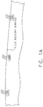
- the synthetic jet (or any number thereof) may be integrated as desired on to or with suitable fluid boundary surfaces as shown, for example, in Figure 1A .
- the actuators 105, 110 may comprise one or more piezoelectric, electro-strictive, or electromagnet elements.
- the pistons 115, 120 may each comprise a rigid body or may be flexible and periodically bowed, bent, or otherwise deformed to change the volume 125 of the cavity.
- the pumping action of pistons 115 and 120 generates a synthetic jet 135 by cyclically pulling in and expelling a fluid, for example, air, through the aperture 130.
- Arrows 140, 145 show the pumping direction of pistons 115 and 120, respectively.
- the pistons 115, 120 are each moving away and toward the volume in a synchronized fashion and thus are effective at radiating sound external to the synthetic jet generator 100.
- the jet is provided by the pistons 115, 120 which may be considered to represent a sound point source formed by the synchronous pumping action. It should be understood that while the cyclic suction and expulsion are described herein as being achieved using actuators and pistons, any suitable mechanism using any suitable technique may be used to effect the actions of the generator for generating a synthetic jet.
- a waveguide structure that introduces a phase difference of approximately 180 degrees in the sound waves radiating from the jet (such as from each of the pistons 115, 120) may be used to substantially cancel the noise from the pistons.
- the jet may be operated at a substantially fixed frequency, and may use a structure with dimensions determined from the operating frequency to effect the noise cancellation.
- Figure 2 depicts a cross section of an exemplary synthetic jet muffler 200 according the aspects of the disclosed embodiment.
- the synthetic jet muffler 200 may include an exit end 210 and at least two propagation paths for conducting sound waves generated by a synthetic jet generator 225.
- the synthetic jet muffler may also include at least one aperture 260, corresponding to one or more apertures 265 of the synthetic jet generator 225.
- a first propagation path 215 may be provided for conducting a first sound wave 220, emitted by the synthetic jet 225 to the exit end 210.
- the first sound wave 220 may be generated by the action of a first piston 230 of the synthetic jet 225 driven by an actuator 235.
- the synthetic jet muffler may also include a shroud 240 for effecting a second propagation path 270 for conducting a second sound wave 245 emitted by the synthetic jet generator 225 in a direction opposite to the first sound wave 220.
- the second sound wave 245 may be generated by the action of a second piston 250 of the synthetic jet generator 225 driven by an actuator 255 and the shroud 240 may be arranged to conduct the second sound wave 245 to the exit end 210.
- the shroud 240 may include at least two structures 275, 280 forming a generally annular configuration.
- the structures may be arranged as a first cylinder 280 surrounded by a second cylinder 275, both having an opening in a common plane 285 forming the exit end 210 of the synthetic jet muffler 200.
- the first cylinder 280 may enclose the synthetic jet generator 225 and have an additional open end 288, where the open ends of the first cylinder effect opposing propagation paths for the first and second sound waves 220, 245.
- the first cylinder 280 may also include an opening 290 to allow fluid to flow through aperture 265 to produce the synthetic jet.
- the second cylinder 275 may include a closed end 292 utilized to provide the second propagation path 270 to the exit end 210 for the second sound wave 245.
- the second cylinder 275 may include the aperture 260, corresponding to one or more apertures 265 of the synthetic jet generator 225. While the structures 275, 280 are described as cylinders and as a first cylinder surrounded by a second cylinder, it should be understood that the disclosed embodiment may include any other structures arranged in any other configurations so long as the noise cancelling effects via phase shift and direction matching of sound waves from the synthetic jet are achieved.
- Figures 3A and 3B show a cross sectional and an isometric view, respectively, of aspects of an exemplary synthetic jet muffler.
- the shroud 240 may be further arranged so that the distances traveled by the first and second sound waves 220, 245 are different and operate to effect noise cancellation at the exit end 210.
- the shroud may provide a difference in distances travelled by the first and second sound waves 220, 245 that effects a phase difference between the first and second sound waves 220, 245 substantially cancelling the first and second sound waves at the exit end 210 of the synthetic jet muffler.
- the shroud may be arranged to provide a difference in distances travelled by the first and second sound waves that may correspond to n* ⁇ /2 where n is an odd integer and A is a wavelength of the substantially fixed frequency.
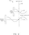
- Figure 4 shows an exemplary schematic diagram 400 of sound pressure along the propagation paths of the synthetic jet muffler 200.
- the sound pressure 410 generated by the first piston 230 is substantially out of phase with the sound pressure 415 generated by the second piston 250.
- the sound pressure waves 410, 415 reach the exit 210 of the synthetic jet muffler, sound produced by the sound pressure waves is substantially cancelled.
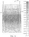
- a model 500 of the synthetic jet muffler 200 using finite element analysis is shown in Figure 5 .
- the model 400 shows a cross section of the results of modeling the propagation path 270 of the second sound wave 255, and shows the pressure distribution of the acoustic mode resulting from the geometry of the synthetic jet muffler at or near a drive frequency of the exemplary synthetic jet generator 225.
- the aspects of the disclosed embodiment may provide effective noise cancellation over a range of frequencies, however, as the frequency of operation of the synthetic jet generator increases, diffraction effects of the sound waves may impact the amount of cancellation achieved.
- the pistons operate as uniform radiators and diffraction effects of the sound waves may be negligible.
- effective noise cancellation may require matching the directivity of sound sources resulting from sound waves 220, 245 as they pass the exit opening 210, in addition to providing a phase difference between the first and second sound waves 220.
- a mismatch of directivity at higher frequencies may cause incomplete cancellation of the sound field at off-axis locations, while cancellation may still be effective at the exit end of the synthetic jet muffler.
- Figure 6 shows a schematic diagram of an exemplary aspect where one or more synthetic jets 600 with mufflers 605 according to the disclosed embodiment may be used in combination with an airfoil 610 to achieve active flow control.
- the one or more synthetic jets 600 may be used to control flow separation by adding or subtracting energy from a fluid boundary layer 615.
- the one or more synthetic jets 600 may be used to decrease drag by suppressing flow separation or shedding in order to prevent leading edge stall at high angles of attack.
- An exemplary airfoil with synthetic jets is shown in US Patent No.: 5,938,404 , incorporated by reference in its entirety.
- the synthetic jet 600 may produce high sound levels inside the airfoil due to the reciprocating, single frequency action of the pumping mechanism and the addition of the muffler 605 may at least operate to cancel this noise.
- the locations, arrangement and number of synthetic jets 600 and mufflers 605 in Figure 6 are exemplary only and that any suitable configuration and quantity may be utilized.
- the synthetic jets 600 and mufflers 605 may be mounted on a surface or embedded within the airfoil, and may be have any orientation so long as the noise is attenuated or cancelled.
- a synthetic jet muffler includes an exit end, a propagation path for conducting a first sound wave emitted by a synthetic jet generator to the exit end, and a shroud for conducting a second sound wave emitted from the synthetic jet generator in a direction opposite to the first sound wave to the exit end, wherein the shroud is disposed so that the first and second sound waves travel different distances to effect noise cancellation at the exit end.
- the difference in distances travelled by the first and second sound waves effect a phase difference between the first and second sound waves substantially cancelling the first and second sound waves at the exit end of the synthetic jet muffler.
- the synthetic jet generator operates at a substantially fixed frequency.
- the difference in distances travelled by the first and second sound waves corresponds to n* ⁇ /2 where n is an odd integer and ⁇ is a wavelength of the substantially fixed frequency.
- the synthetic jet generator comprises synchronized opposing synthetic jet actuators.
- the synchronized opposing synthetic jet actuators comprise opposing pistons.
- the shroud is positioned to surround the synthetic jet and comprises at least one aperture for conducting a flow generated by the synthetic jet.
- an apparatus in accordance with one or more aspects of the disclosed embodiment, includes a synthetic jet having two or more actuators producing sound waves in different directions, and a shroud surrounding the synthetic jet, the shroud having an open end and a waveguide structure having propagation paths of different lengths for the sound waves to effect noise cancellation at the open end.
- the difference in lengths of the propagation paths effect a phase difference between the sound waves substantially cancelling the sound waves at the open end.
- the synthetic jet actuators operate at a substantially fixed frequency.
- the difference in distances of the propagation paths corresponds to n* ⁇ /2 where n is an odd integer and ⁇ is a wavelength of the substantially fixed frequency.
- the two or more actuators operate synchronously in opposing directions.
- the two or more actuators comprise opposing pistons.
- the shroud comprises at least one aperture for conducting a flow generated by the synthetic jet.
- a method of reducing noise produced by a synthetic jet includes operating the synthetic jet at a substantially fixed frequency to pump a fluid, and conducting sound waves produced in different directions by the synthetic jet through waveguides having different lengths relative to the substantially fixed frequency for effecting noise cancellation at a common exit plane of the waveguides.
- the different waveguide lengths effect a phase difference between the sound waves substantially cancelling the sound waves at the common exit plane.
- a difference in the waveguide lengths corresponds to n* ⁇ /2 where n is an odd integer and ⁇ is a wavelength of the substantially fixed frequency.
- the synthetic jet comprises two or more actuators operating synchronously in opposing directions.
Landscapes
- Engineering & Computer Science (AREA)
- Aviation & Aerospace Engineering (AREA)
- Chemical & Material Sciences (AREA)
- Combustion & Propulsion (AREA)
- Mechanical Engineering (AREA)
- General Engineering & Computer Science (AREA)
- Exhaust Silencers (AREA)
- Structures Of Non-Positive Displacement Pumps (AREA)
Claims (12)
- Synthetischer Strahlschalldämpfer (200), der aufweist:ein Austrittsende (210);einen Ausbreitungsweg (215) zum Leiten einer ersten Schallwelle (220), die von einem synthetischen Strahlgenerator (225) emittiert wird, hin zu dem Austrittsende (210); undeine Ummantelung (240), die den synthetischen Strahl umgibt, wobei die Ummantelung (240) ein offenes Ende (210) aufweist,gekennzeichnet durcheine Hohlleiterstruktur mit Ausbreitungswegen (215, 270) unterschiedlicher Länge für die Schallwellen (220, 245), um eine Geräuschunterdrückung an dem offenen Ende (210) zu bewirken, wobei die Ummantelung (240) eine zweite Schallwelle (245) leitet, die von dem synthetischen Strahlgenerator (225) in einer Richtung entgegengesetzt zu der ersten Schallwelle (220) zu dem Austrittsende (210) emittiert wird, wobei die Ummantelung (240) so angeordnet ist, dass die erste und die zweite Schallwelle (220, 245) unterschiedliche Entfernungen zurücklegen, um eine Geräuschunterdrückung an dem Austrittsende (210) zu bewirken.
- Synthetischer Strahlschalldämpfer nach Anspruch 1, wobei die Differenz der von der ersten und der zweiten Schallwelle (220, 245) zurückgelegten Entfernungen eine Phasendifferenz zwischen der ersten und der zweiten Schallwelle (220, 245) bewirkt, die die erste und die zweite Schallwelle (220, 245) an dem Austrittsende (210) des synthetischen Strahlschalldämpfers (200) im Wesentlichen auslöscht.
- Synthetischer Strahlschalldämpfer nach Anspruch 1 oder 2, wobei der synthetische Strahlgenerator (225) mit einer im Wesentlichen festen Frequenz arbeitet.
- Synthetischer Strahlschalldämpfer nach Anspruch 3, wobei die Differenz der von der ersten und der zweiten Schallwelle (220, 245) zurückgelegten Entfernungen n*λ/2 entspricht, wobei n eine ungerade ganze Zahl ist und wobei λ eine Wellenlänge der im Wesentlichen festen Frequenz ist.
- Synthetischer Strahlschalldämpfer nach einem der Ansprüche 1 bis 4, wobei der synthetische Strahlgenerator (225) synchronisierte, gegenüberliegende synthetische Strahlaktuatoren (105, 110) aufweist.
- Synthetischer Strahlschalldämpfer nach Anspruch 5, wobei die synchronisierten, gegenüberliegenden synthetischen Strahlaktuatoren (105, 110) gegenüberliegende Kolben (115, 120) aufweisen.
- Synthetischer Strahlschalldämpfer nach einem der Ansprüche 1 bis 6, wobei die Ummantelung (240) so angeordnet ist, dass sie den synthetischen Strahl umgibt, und mindestens eine Öffnung (260) zum Leiten einer durch den synthetischen Strahl erzeugten Strömung aufweist.
- Synthetischer Strahlschalldämpfer nach Anspruch 5, wobei die synthetischen Strahlaktuatoren (105, 110) mit einer im Wesentlichen festen Frequenz arbeiten.
- Verfahren zum Reduzieren von Geräuschen, die durch einen synthetischen Strahl erzeugt werden, mit den Schritten
Betreiben des synthetischen Strahls mit einer im Wesentlichen festen Frequenz, um ein Fluid zu pumpen;
Leiten von Schallwellen (220, 245), die von dem synthetischen Strahl in verschiedene Richtungen erzeugt werden, durch Hohlleiter (215, 270) mit unterschiedlichen Längen relativ zu der im Wesentlichen festen Frequenz hindurch, um eine Geräuschunterdrückung an einem gemeinsamen Austritt (210) der Hohlleiter (215, 270) zu bewirken. - Verfahren nach Anspruch 9, wobei die unterschiedlichen Hohlleiterlängen eine Phasendifferenz zwischen den Schallwellen (220, 245) bewirken, die die Schallwellen (220, 245) an dem gemeinsamen Austritt (210) im Wesentlichen auslöscht.
- Verfahren nach Anspruch 9 oder 10, wobei eine Differenz in den Hohlleiterlängen n*λ/2 entspricht, wobei n eine ungerade ganze Zahl ist und wobei λ eine Wellenlänge der im Wesentlichen festen Frequenz ist.
- Verfahren nach einem der Ansprüche 9 bis 11, wobei der synthetische Strahl zwei oder mehr Aktuatoren (105, 110) aufweist, die synchron in entgegengesetzte Richtungen arbeiten.
Applications Claiming Priority (1)
| Application Number | Priority Date | Filing Date | Title |
|---|---|---|---|
| US14/055,560 US9027702B2 (en) | 2013-10-16 | 2013-10-16 | Synthetic jet muffler |
Publications (2)
| Publication Number | Publication Date |
|---|---|
| EP2873609A1 EP2873609A1 (de) | 2015-05-20 |
| EP2873609B1 true EP2873609B1 (de) | 2018-11-28 |
Family
ID=51454585
Family Applications (1)
| Application Number | Title | Priority Date | Filing Date |
|---|---|---|---|
| EP14183188.3A Not-in-force EP2873609B1 (de) | 2013-10-16 | 2014-09-02 | Synthetischer Strahlschalldämpfer |
Country Status (4)
| Country | Link |
|---|---|
| US (1) | US9027702B2 (de) |
| EP (1) | EP2873609B1 (de) |
| CN (1) | CN104554702B (de) |
| CA (1) | CA2859210C (de) |
Families Citing this family (6)
| Publication number | Priority date | Publication date | Assignee | Title |
|---|---|---|---|---|
| US9765767B2 (en) * | 2015-05-11 | 2017-09-19 | The Boeing Company | Synthetic vacuum generator |
| WO2017189474A1 (en) | 2016-04-25 | 2017-11-02 | Rensselaer Polytechnic Institute | Methods and apparatus for controlling flow fields |
| US10787245B2 (en) | 2016-06-01 | 2020-09-29 | The Boeing Company | Distributed compressor for improved integration and performance of an active fluid flow control system |
| CN107894588B (zh) * | 2017-11-13 | 2020-11-13 | 北京小米移动软件有限公司 | 移动终端、距离测量方法、尺寸测量方法及装置 |
| CN109630379B (zh) * | 2018-12-06 | 2020-04-24 | 珠海凌达压缩机有限公司 | 降噪系统、降噪方法及电器设备 |
| WO2021138305A1 (en) | 2019-12-29 | 2021-07-08 | Actasys, Inc. | Novel design and production technique of synthetic jet actuators |
Citations (2)
| Publication number | Priority date | Publication date | Assignee | Title |
|---|---|---|---|---|
| EP1762725A1 (de) * | 2004-03-18 | 2007-03-14 | Sony Corporation | Gasstrahlvorrichtung, elektronische vorrichtung und gasstrahlverfahren |
| WO2008065602A1 (en) * | 2006-11-30 | 2008-06-05 | Koninklijke Philips Electronics N.V. | Pulsating cooling system |
Family Cites Families (18)
| Publication number | Priority date | Publication date | Assignee | Title |
|---|---|---|---|---|
| US3948348A (en) * | 1975-05-12 | 1976-04-06 | General Motors Corporation | Wave interference silencer construction |
| US3948349A (en) * | 1975-05-12 | 1976-04-06 | General Motors Corporation | Wave interference silencer |
| US4199936A (en) * | 1975-12-24 | 1980-04-29 | The Boeing Company | Gas turbine engine combustion noise suppressor |
| US4648807A (en) * | 1985-05-14 | 1987-03-10 | The Garrett Corporation | Compact piezoelectric fluidic air supply pump |
| CN2091953U (zh) * | 1991-04-06 | 1992-01-01 | 北京清河毛纺织厂 | 高速射流消声器 |
| US5938404A (en) | 1997-06-05 | 1999-08-17 | Mcdonnell Douglas Helicopter Company | Oscillating air jets on aerodynamic surfaces |
| US5983944A (en) * | 1998-03-20 | 1999-11-16 | Niv; Shaul E. | Apparatus for active fluid control |
| US6796859B1 (en) * | 2000-11-16 | 2004-09-28 | Bombardier Recreational Products Inc. | Air intake silencer |
| US6471477B2 (en) * | 2000-12-22 | 2002-10-29 | The Boeing Company | Jet actuators for aerodynamic surfaces |
| JP4677744B2 (ja) * | 2003-11-04 | 2011-04-27 | ソニー株式会社 | 噴流発生装置、電子機器及び噴流発生方法 |
| US6994297B1 (en) * | 2004-10-27 | 2006-02-07 | The Boeing Company | Method and apparatus for controlling a vehicle |
| US8069910B2 (en) * | 2005-10-12 | 2011-12-06 | Nuventix, Inc. | Acoustic resonator for synthetic jet generation for thermal management |
| US8122732B2 (en) * | 2006-09-07 | 2012-02-28 | Lg Electronics Inc. | Refrigerator with noise reduction structure using inverse phase sound wave |
| US8006917B2 (en) * | 2008-08-26 | 2011-08-30 | General Electric Company | Method and apparatus for reducing acoustic noise in a synthetic jet |
| EP2282335A1 (de) * | 2009-08-05 | 2011-02-09 | Siemens Aktiengesellschaft | Kühlvorrichtung und Verfahren |
| US8596568B2 (en) * | 2011-04-26 | 2013-12-03 | Hamilton Sundstrand Corporation | Exhaust silencer with baffles |
| US9215520B2 (en) * | 2012-08-15 | 2015-12-15 | General Electric Company | Multi-function synthetic jet and method of manufacturing same |
| CN202834561U (zh) * | 2012-09-07 | 2013-03-27 | 佛山市海天调味食品股份有限公司 | 一种蒸汽喷射消声器 |
-
2013
- 2013-10-16 US US14/055,560 patent/US9027702B2/en not_active Expired - Fee Related
-
2014
- 2014-08-12 CA CA2859210A patent/CA2859210C/en not_active Expired - Fee Related
- 2014-09-02 EP EP14183188.3A patent/EP2873609B1/de not_active Not-in-force
- 2014-10-13 CN CN201410538236.0A patent/CN104554702B/zh not_active Expired - Fee Related
Patent Citations (2)
| Publication number | Priority date | Publication date | Assignee | Title |
|---|---|---|---|---|
| EP1762725A1 (de) * | 2004-03-18 | 2007-03-14 | Sony Corporation | Gasstrahlvorrichtung, elektronische vorrichtung und gasstrahlverfahren |
| WO2008065602A1 (en) * | 2006-11-30 | 2008-06-05 | Koninklijke Philips Electronics N.V. | Pulsating cooling system |
Also Published As
| Publication number | Publication date |
|---|---|
| US9027702B2 (en) | 2015-05-12 |
| EP2873609A1 (de) | 2015-05-20 |
| CN104554702A (zh) | 2015-04-29 |
| CN104554702B (zh) | 2018-06-12 |
| US20150101886A1 (en) | 2015-04-16 |
| CA2859210C (en) | 2017-04-04 |
| CA2859210A1 (en) | 2015-04-16 |
Similar Documents
| Publication | Publication Date | Title |
|---|---|---|
| EP2873609B1 (de) | Synthetischer Strahlschalldämpfer | |
| US7688583B1 (en) | Synthetic jet and method of making same | |
| JP6555845B2 (ja) | 多機能シンセティックジェットおよび同製作の方法 | |
| US5590849A (en) | Active noise control using an array of plate radiators and acoustic resonators | |
| US8006917B2 (en) | Method and apparatus for reducing acoustic noise in a synthetic jet | |
| US8752775B2 (en) | Method and apparatus for reducing acoustic noise in a synthetic jet | |
| US20120247109A1 (en) | Gas turbine and air intake manifold | |
| US5618010A (en) | Active noise control using a tunable plate radiator | |
| CN104176236B (zh) | 波纹管合成射流 | |
| CN111564149A (zh) | 基于可控阻抗边界的空腔结构噪声控制方法及控制装置 | |
| EP2843244B1 (de) | Unterdrückung von durch Stöße hervorgerufener Luftstromtrennung | |
| CN105026050A (zh) | 低共振声音合成喷射器结构 | |
| US5584447A (en) | Noise control using a plate radiator and an acoustic resonator | |
| CN114787908B (zh) | 谐振补片和设置有这种补片的声学处理单元 | |
| EP0676012A1 (de) | Antischallanordnung für mehrstufiges schaufelgitter | |
| JP5379148B2 (ja) | 乱流エアジェット内の渦構造を制御する装置と方法 | |
| Kordik et al. | Experiments on resonance frequencies of synthetic jet actuators | |
| Yee et al. | High-speed air microjet arrays produced using acoustic streaming for micro propulsion | |
| JP4626299B2 (ja) | ダクト内騒音制御方法及び装置 | |
| Zeng et al. | A passive, blade-mounted ultrasonic bat deterrent for wind turbines | |
| JP7340960B2 (ja) | 騒音低減装置 | |
| CN105781933B (zh) | 压缩机排气消音结构 | |
| US7273130B2 (en) | Device and method for active soundproofing, and power unit for aeroplanes | |
| Kim et al. | Piezoelectric smart panels for broadband noise reduction | |
| JPS62251405A (ja) | 蒸気タ−ビンの水滴微細化装置 |
Legal Events
| Date | Code | Title | Description |
|---|---|---|---|
| PUAI | Public reference made under article 153(3) epc to a published international application that has entered the european phase |
Free format text: ORIGINAL CODE: 0009012 |
|
| 17P | Request for examination filed |
Effective date: 20140902 |
|
| AK | Designated contracting states |
Kind code of ref document: A1 Designated state(s): AL AT BE BG CH CY CZ DE DK EE ES FI FR GB GR HR HU IE IS IT LI LT LU LV MC MK MT NL NO PL PT RO RS SE SI SK SM TR |
|
| AX | Request for extension of the european patent |
Extension state: BA ME |
|
| R17P | Request for examination filed (corrected) |
Effective date: 20151026 |
|
| RBV | Designated contracting states (corrected) |
Designated state(s): AL AT BE BG CH CY CZ DE DK EE ES FI FR GB GR HR HU IE IS IT LI LT LU LV MC MK MT NL NO PL PT RO RS SE SI SK SM TR |
|
| STAA | Information on the status of an ep patent application or granted ep patent |
Free format text: STATUS: EXAMINATION IS IN PROGRESS |
|
| 17Q | First examination report despatched |
Effective date: 20171116 |
|
| GRAP | Despatch of communication of intention to grant a patent |
Free format text: ORIGINAL CODE: EPIDOSNIGR1 |
|
| STAA | Information on the status of an ep patent application or granted ep patent |
Free format text: STATUS: GRANT OF PATENT IS INTENDED |
|
| INTG | Intention to grant announced |
Effective date: 20180615 |
|
| GRAS | Grant fee paid |
Free format text: ORIGINAL CODE: EPIDOSNIGR3 |
|
| GRAA | (expected) grant |
Free format text: ORIGINAL CODE: 0009210 |
|
| STAA | Information on the status of an ep patent application or granted ep patent |
Free format text: STATUS: THE PATENT HAS BEEN GRANTED |
|
| AK | Designated contracting states |
Kind code of ref document: B1 Designated state(s): AL AT BE BG CH CY CZ DE DK EE ES FI FR GB GR HR HU IE IS IT LI LT LU LV MC MK MT NL NO PL PT RO RS SE SI SK SM TR |
|
| REG | Reference to a national code |
Ref country code: CH Ref legal event code: EP |
|
| REG | Reference to a national code |
Ref country code: DE Ref legal event code: R096 Ref document number: 602014036827 Country of ref document: DE |
|
| REG | Reference to a national code |
Ref country code: AT Ref legal event code: REF Ref document number: 1069921 Country of ref document: AT Kind code of ref document: T Effective date: 20181215 |
|
| REG | Reference to a national code |
Ref country code: IE Ref legal event code: FG4D |
|
| REG | Reference to a national code |
Ref country code: NL Ref legal event code: MP Effective date: 20181128 |
|
| REG | Reference to a national code |
Ref country code: LT Ref legal event code: MG4D |
|
| REG | Reference to a national code |
Ref country code: AT Ref legal event code: MK05 Ref document number: 1069921 Country of ref document: AT Kind code of ref document: T Effective date: 20181128 |
|
| PG25 | Lapsed in a contracting state [announced via postgrant information from national office to epo] |
Ref country code: HR Free format text: LAPSE BECAUSE OF FAILURE TO SUBMIT A TRANSLATION OF THE DESCRIPTION OR TO PAY THE FEE WITHIN THE PRESCRIBED TIME-LIMIT Effective date: 20181128 Ref country code: LT Free format text: LAPSE BECAUSE OF FAILURE TO SUBMIT A TRANSLATION OF THE DESCRIPTION OR TO PAY THE FEE WITHIN THE PRESCRIBED TIME-LIMIT Effective date: 20181128 Ref country code: AT Free format text: LAPSE BECAUSE OF FAILURE TO SUBMIT A TRANSLATION OF THE DESCRIPTION OR TO PAY THE FEE WITHIN THE PRESCRIBED TIME-LIMIT Effective date: 20181128 Ref country code: BG Free format text: LAPSE BECAUSE OF FAILURE TO SUBMIT A TRANSLATION OF THE DESCRIPTION OR TO PAY THE FEE WITHIN THE PRESCRIBED TIME-LIMIT Effective date: 20190228 Ref country code: FI Free format text: LAPSE BECAUSE OF FAILURE TO SUBMIT A TRANSLATION OF THE DESCRIPTION OR TO PAY THE FEE WITHIN THE PRESCRIBED TIME-LIMIT Effective date: 20181128 Ref country code: LV Free format text: LAPSE BECAUSE OF FAILURE TO SUBMIT A TRANSLATION OF THE DESCRIPTION OR TO PAY THE FEE WITHIN THE PRESCRIBED TIME-LIMIT Effective date: 20181128 Ref country code: ES Free format text: LAPSE BECAUSE OF FAILURE TO SUBMIT A TRANSLATION OF THE DESCRIPTION OR TO PAY THE FEE WITHIN THE PRESCRIBED TIME-LIMIT Effective date: 20181128 Ref country code: NO Free format text: LAPSE BECAUSE OF FAILURE TO SUBMIT A TRANSLATION OF THE DESCRIPTION OR TO PAY THE FEE WITHIN THE PRESCRIBED TIME-LIMIT Effective date: 20190228 Ref country code: IS Free format text: LAPSE BECAUSE OF FAILURE TO SUBMIT A TRANSLATION OF THE DESCRIPTION OR TO PAY THE FEE WITHIN THE PRESCRIBED TIME-LIMIT Effective date: 20190328 |
|
| PG25 | Lapsed in a contracting state [announced via postgrant information from national office to epo] |
Ref country code: GR Free format text: LAPSE BECAUSE OF FAILURE TO SUBMIT A TRANSLATION OF THE DESCRIPTION OR TO PAY THE FEE WITHIN THE PRESCRIBED TIME-LIMIT Effective date: 20190301 Ref country code: PT Free format text: LAPSE BECAUSE OF FAILURE TO SUBMIT A TRANSLATION OF THE DESCRIPTION OR TO PAY THE FEE WITHIN THE PRESCRIBED TIME-LIMIT Effective date: 20190328 Ref country code: RS Free format text: LAPSE BECAUSE OF FAILURE TO SUBMIT A TRANSLATION OF THE DESCRIPTION OR TO PAY THE FEE WITHIN THE PRESCRIBED TIME-LIMIT Effective date: 20181128 Ref country code: AL Free format text: LAPSE BECAUSE OF FAILURE TO SUBMIT A TRANSLATION OF THE DESCRIPTION OR TO PAY THE FEE WITHIN THE PRESCRIBED TIME-LIMIT Effective date: 20181128 Ref country code: SE Free format text: LAPSE BECAUSE OF FAILURE TO SUBMIT A TRANSLATION OF THE DESCRIPTION OR TO PAY THE FEE WITHIN THE PRESCRIBED TIME-LIMIT Effective date: 20181128 |
|
| PG25 | Lapsed in a contracting state [announced via postgrant information from national office to epo] |
Ref country code: NL Free format text: LAPSE BECAUSE OF FAILURE TO SUBMIT A TRANSLATION OF THE DESCRIPTION OR TO PAY THE FEE WITHIN THE PRESCRIBED TIME-LIMIT Effective date: 20181128 |
|
| PG25 | Lapsed in a contracting state [announced via postgrant information from national office to epo] |
Ref country code: PL Free format text: LAPSE BECAUSE OF FAILURE TO SUBMIT A TRANSLATION OF THE DESCRIPTION OR TO PAY THE FEE WITHIN THE PRESCRIBED TIME-LIMIT Effective date: 20181128 Ref country code: DK Free format text: LAPSE BECAUSE OF FAILURE TO SUBMIT A TRANSLATION OF THE DESCRIPTION OR TO PAY THE FEE WITHIN THE PRESCRIBED TIME-LIMIT Effective date: 20181128 Ref country code: CZ Free format text: LAPSE BECAUSE OF FAILURE TO SUBMIT A TRANSLATION OF THE DESCRIPTION OR TO PAY THE FEE WITHIN THE PRESCRIBED TIME-LIMIT Effective date: 20181128 Ref country code: IT Free format text: LAPSE BECAUSE OF FAILURE TO SUBMIT A TRANSLATION OF THE DESCRIPTION OR TO PAY THE FEE WITHIN THE PRESCRIBED TIME-LIMIT Effective date: 20181128 |
|
| REG | Reference to a national code |
Ref country code: DE Ref legal event code: R097 Ref document number: 602014036827 Country of ref document: DE |
|
| PG25 | Lapsed in a contracting state [announced via postgrant information from national office to epo] |
Ref country code: SK Free format text: LAPSE BECAUSE OF FAILURE TO SUBMIT A TRANSLATION OF THE DESCRIPTION OR TO PAY THE FEE WITHIN THE PRESCRIBED TIME-LIMIT Effective date: 20181128 Ref country code: EE Free format text: LAPSE BECAUSE OF FAILURE TO SUBMIT A TRANSLATION OF THE DESCRIPTION OR TO PAY THE FEE WITHIN THE PRESCRIBED TIME-LIMIT Effective date: 20181128 Ref country code: SM Free format text: LAPSE BECAUSE OF FAILURE TO SUBMIT A TRANSLATION OF THE DESCRIPTION OR TO PAY THE FEE WITHIN THE PRESCRIBED TIME-LIMIT Effective date: 20181128 Ref country code: RO Free format text: LAPSE BECAUSE OF FAILURE TO SUBMIT A TRANSLATION OF THE DESCRIPTION OR TO PAY THE FEE WITHIN THE PRESCRIBED TIME-LIMIT Effective date: 20181128 |
|
| PLBE | No opposition filed within time limit |
Free format text: ORIGINAL CODE: 0009261 |
|
| STAA | Information on the status of an ep patent application or granted ep patent |
Free format text: STATUS: NO OPPOSITION FILED WITHIN TIME LIMIT |
|
| PG25 | Lapsed in a contracting state [announced via postgrant information from national office to epo] |
Ref country code: SI Free format text: LAPSE BECAUSE OF FAILURE TO SUBMIT A TRANSLATION OF THE DESCRIPTION OR TO PAY THE FEE WITHIN THE PRESCRIBED TIME-LIMIT Effective date: 20181128 |
|
| 26N | No opposition filed |
Effective date: 20190829 |
|
| PG25 | Lapsed in a contracting state [announced via postgrant information from national office to epo] |
Ref country code: TR Free format text: LAPSE BECAUSE OF FAILURE TO SUBMIT A TRANSLATION OF THE DESCRIPTION OR TO PAY THE FEE WITHIN THE PRESCRIBED TIME-LIMIT Effective date: 20181128 |
|
| PG25 | Lapsed in a contracting state [announced via postgrant information from national office to epo] |
Ref country code: MC Free format text: LAPSE BECAUSE OF FAILURE TO SUBMIT A TRANSLATION OF THE DESCRIPTION OR TO PAY THE FEE WITHIN THE PRESCRIBED TIME-LIMIT Effective date: 20181128 |
|
| REG | Reference to a national code |
Ref country code: CH Ref legal event code: PL |
|
| PG25 | Lapsed in a contracting state [announced via postgrant information from national office to epo] |
Ref country code: LI Free format text: LAPSE BECAUSE OF NON-PAYMENT OF DUE FEES Effective date: 20190930 Ref country code: IE Free format text: LAPSE BECAUSE OF NON-PAYMENT OF DUE FEES Effective date: 20190902 Ref country code: LU Free format text: LAPSE BECAUSE OF NON-PAYMENT OF DUE FEES Effective date: 20190902 Ref country code: CH Free format text: LAPSE BECAUSE OF NON-PAYMENT OF DUE FEES Effective date: 20190930 |
|
| REG | Reference to a national code |
Ref country code: BE Ref legal event code: MM Effective date: 20190930 |
|
| PG25 | Lapsed in a contracting state [announced via postgrant information from national office to epo] |
Ref country code: BE Free format text: LAPSE BECAUSE OF NON-PAYMENT OF DUE FEES Effective date: 20190930 |
|
| PG25 | Lapsed in a contracting state [announced via postgrant information from national office to epo] |
Ref country code: CY Free format text: LAPSE BECAUSE OF FAILURE TO SUBMIT A TRANSLATION OF THE DESCRIPTION OR TO PAY THE FEE WITHIN THE PRESCRIBED TIME-LIMIT Effective date: 20181128 |
|
| PG25 | Lapsed in a contracting state [announced via postgrant information from national office to epo] |
Ref country code: MT Free format text: LAPSE BECAUSE OF FAILURE TO SUBMIT A TRANSLATION OF THE DESCRIPTION OR TO PAY THE FEE WITHIN THE PRESCRIBED TIME-LIMIT Effective date: 20181128 Ref country code: HU Free format text: LAPSE BECAUSE OF FAILURE TO SUBMIT A TRANSLATION OF THE DESCRIPTION OR TO PAY THE FEE WITHIN THE PRESCRIBED TIME-LIMIT; INVALID AB INITIO Effective date: 20140902 |
|
| PGFP | Annual fee paid to national office [announced via postgrant information from national office to epo] |
Ref country code: FR Payment date: 20210927 Year of fee payment: 8 |
|
| PGFP | Annual fee paid to national office [announced via postgrant information from national office to epo] |
Ref country code: GB Payment date: 20210927 Year of fee payment: 8 Ref country code: DE Payment date: 20210929 Year of fee payment: 8 |
|
| PG25 | Lapsed in a contracting state [announced via postgrant information from national office to epo] |
Ref country code: MK Free format text: LAPSE BECAUSE OF FAILURE TO SUBMIT A TRANSLATION OF THE DESCRIPTION OR TO PAY THE FEE WITHIN THE PRESCRIBED TIME-LIMIT Effective date: 20181128 |
|
| REG | Reference to a national code |
Ref country code: DE Ref legal event code: R119 Ref document number: 602014036827 Country of ref document: DE |
|
| GBPC | Gb: european patent ceased through non-payment of renewal fee |
Effective date: 20220902 |
|
| PG25 | Lapsed in a contracting state [announced via postgrant information from national office to epo] |
Ref country code: FR Free format text: LAPSE BECAUSE OF NON-PAYMENT OF DUE FEES Effective date: 20220930 Ref country code: DE Free format text: LAPSE BECAUSE OF NON-PAYMENT OF DUE FEES Effective date: 20230401 |
|
| PG25 | Lapsed in a contracting state [announced via postgrant information from national office to epo] |
Ref country code: GB Free format text: LAPSE BECAUSE OF NON-PAYMENT OF DUE FEES Effective date: 20220902 |