EP2873383B1 - Dispositif d'ancrage d'os polyaxial doté d'un angle de pivot élargi - Google Patents
Dispositif d'ancrage d'os polyaxial doté d'un angle de pivot élargi Download PDFInfo
- Publication number
- EP2873383B1 EP2873383B1 EP13192978.8A EP13192978A EP2873383B1 EP 2873383 B1 EP2873383 B1 EP 2873383B1 EP 13192978 A EP13192978 A EP 13192978A EP 2873383 B1 EP2873383 B1 EP 2873383B1
- Authority
- EP
- European Patent Office
- Prior art keywords
- cap member
- receiving part
- head
- bone anchoring
- rod
- Prior art date
- Legal status (The legal status is an assumption and is not a legal conclusion. Google has not performed a legal analysis and makes no representation as to the accuracy of the status listed.)
- Active
Links
- 238000004873 anchoring Methods 0.000 title claims description 85
- 210000000988 bone and bone Anatomy 0.000 title claims description 80
- 230000004308 accommodation Effects 0.000 claims description 22
- 238000003780 insertion Methods 0.000 claims description 5
- 230000037431 insertion Effects 0.000 claims description 5
- 239000007943 implant Substances 0.000 description 5
- 239000004696 Poly ether ether ketone Substances 0.000 description 2
- 230000006835 compression Effects 0.000 description 2
- 238000007906 compression Methods 0.000 description 2
- 229910001000 nickel titanium Inorganic materials 0.000 description 2
- 229920002530 polyetherether ketone Polymers 0.000 description 2
- 239000007787 solid Substances 0.000 description 2
- 230000006641 stabilisation Effects 0.000 description 2
- 238000011105 stabilization Methods 0.000 description 2
- RTEMQAWFIDAILM-XVNBXDOJSA-N CC/C=C(\C1)/CC23C1C2C3 Chemical compound CC/C=C(\C1)/CC23C1C2C3 RTEMQAWFIDAILM-XVNBXDOJSA-N 0.000 description 1
- 241001481828 Glyptocephalus cynoglossus Species 0.000 description 1
- RTAQQCXQSZGOHL-UHFFFAOYSA-N Titanium Chemical compound [Ti] RTAQQCXQSZGOHL-UHFFFAOYSA-N 0.000 description 1
- 239000000560 biocompatible material Substances 0.000 description 1
- 230000008878 coupling Effects 0.000 description 1
- 238000010168 coupling process Methods 0.000 description 1
- 238000005859 coupling reaction Methods 0.000 description 1
- -1 for example Inorganic materials 0.000 description 1
- 238000011065 in-situ storage Methods 0.000 description 1
- 239000000463 material Substances 0.000 description 1
- 230000007246 mechanism Effects 0.000 description 1
- 229910052751 metal Inorganic materials 0.000 description 1
- 239000002184 metal Substances 0.000 description 1
- 229910001092 metal group alloy Inorganic materials 0.000 description 1
- 238000012986 modification Methods 0.000 description 1
- 230000004048 modification Effects 0.000 description 1
- 230000007935 neutral effect Effects 0.000 description 1
- HLXZNVUGXRDIFK-UHFFFAOYSA-N nickel titanium Chemical compound [Ti].[Ti].[Ti].[Ti].[Ti].[Ti].[Ti].[Ti].[Ti].[Ti].[Ti].[Ni].[Ni].[Ni].[Ni].[Ni].[Ni].[Ni].[Ni].[Ni].[Ni].[Ni].[Ni].[Ni].[Ni] HLXZNVUGXRDIFK-UHFFFAOYSA-N 0.000 description 1
- 239000004033 plastic Substances 0.000 description 1
- 229920006260 polyaryletherketone Polymers 0.000 description 1
- 125000006413 ring segment Chemical group 0.000 description 1
- 239000010935 stainless steel Substances 0.000 description 1
- 229910001220 stainless steel Inorganic materials 0.000 description 1
- 238000001356 surgical procedure Methods 0.000 description 1
- 239000010936 titanium Substances 0.000 description 1
- 229910052719 titanium Inorganic materials 0.000 description 1
- 230000007704 transition Effects 0.000 description 1
Images


Classifications
-
- A—HUMAN NECESSITIES
- A61—MEDICAL OR VETERINARY SCIENCE; HYGIENE
- A61B—DIAGNOSIS; SURGERY; IDENTIFICATION
- A61B17/00—Surgical instruments, devices or methods
- A61B17/56—Surgical instruments or methods for treatment of bones or joints; Devices specially adapted therefor
- A61B17/58—Surgical instruments or methods for treatment of bones or joints; Devices specially adapted therefor for osteosynthesis, e.g. bone plates, screws or setting implements
- A61B17/68—Internal fixation devices, including fasteners and spinal fixators, even if a part thereof projects from the skin
- A61B17/70—Spinal positioners or stabilisers, e.g. stabilisers comprising fluid filler in an implant
- A61B17/7001—Screws or hooks combined with longitudinal elements which do not contact vertebrae
- A61B17/7035—Screws or hooks, wherein a rod-clamping part and a bone-anchoring part can pivot relative to each other
- A61B17/7037—Screws or hooks, wherein a rod-clamping part and a bone-anchoring part can pivot relative to each other wherein pivoting is blocked when the rod is clamped
-
- A—HUMAN NECESSITIES
- A61—MEDICAL OR VETERINARY SCIENCE; HYGIENE
- A61B—DIAGNOSIS; SURGERY; IDENTIFICATION
- A61B17/00—Surgical instruments, devices or methods
- A61B17/56—Surgical instruments or methods for treatment of bones or joints; Devices specially adapted therefor
- A61B17/58—Surgical instruments or methods for treatment of bones or joints; Devices specially adapted therefor for osteosynthesis, e.g. bone plates, screws or setting implements
- A61B17/68—Internal fixation devices, including fasteners and spinal fixators, even if a part thereof projects from the skin
- A61B17/70—Spinal positioners or stabilisers, e.g. stabilisers comprising fluid filler in an implant
- A61B17/7001—Screws or hooks combined with longitudinal elements which do not contact vertebrae
- A61B17/7035—Screws or hooks, wherein a rod-clamping part and a bone-anchoring part can pivot relative to each other
Definitions
- the invention relates to a polyaxial bone anchoring device with an enlarged pivot angle.
- the bone anchoring device includes a bone anchoring element for anchoring in a bone or a vertebra, and a receiving part for coupling the bone anchoring element to a stabilization element such as a spinal rod, where the bone anchoring element is pivotable relative to the receiving part and can be pivoted out of a central axis with an enlarged pivot angle.
- the orientation of the enlarged pivot angle may be selectable within a range of 360° around the central axis.
- the bone anchoring element is insertable into the receiving part from a bottom end of the receiving part.
- a polyaxial bone anchoring device with an enlarged pivot angle that is selectable within a range of 360° around a central axis of the receiving part is known from US 2012/0136395 A1 .
- This polyaxial bone anchoring device includes a sleeve-like insert piece that is positioned around a portion of the head of the bone anchoring element and that is configured to pivot in an accommodation space of the receiving part.
- the anchoring element and the insert piece can be locked at respective angles relative to the central axis of the receiving part.
- An enlarged pivot angle may be automatically achieved by pivoting the receiving part relative to the bone anchoring element in a specific direction.
- the bone anchoring element may be inserted from the top end of the receiving part.
- the bone anchoring element together with the sleeve-like insert piece may be inserted from the bottom end of the receiving part.
- a polyaxial bone anchoring device of the bottom loading type is known, for example, from US 2010/0234902-A1 and EP 2 559 390 A1 .
- WO 2007/130007 A1 discloses a different type of a connecting assembly for connecting an implant to a spinal rod.
- the connecting assembly comprises a body having a first channel configured for receipt of the rod and a second channel extending through the body for receipt of at least a portion of an implant.
- the implant may be secured with respect to the body using a collet and an annular ring member which are positionable around a portion of the implant in the second channel.
- a washer is provided having a concave surface translatable along corresponding convex extensions of the body to allow pivoting the collet together with the implant in a specific pivot angle direction with respect to the body.
- a fixing nut is provided.
- the polyaxial bone anchoring device is a bottom loading type bone anchoring device, where the anchoring element is insertable from the bottom end of the receiving part.
- a compressible cap member encompasses at least a portion of the head of the bone anchoring device.
- the cap member is seated in a sleeve-like insert piece that is solid, i.e. without slits or elastic portions. Consequently, the sleeve-like insert piece has a higher strength compared to a flexible sleeve of the same or similar dimensions. That renders the construct robust, because high clamping forces can be exerted onto the cap member that are taken up by the sleeve-like insert piece.
- the cap member is sized such that the head is held therein by friction even if no pressure is exterted onto the cap member.
- the cap member may have a recess or a cut portion that allows to pivot the anchoring element at a larger angle in the direction where the recess or cut portion is located compared to the opposite direction or to another direction.
- An indication mark provided at the cap member may indicate the orientation of the enlarged pivot angle when the cap member is arranged in the receiving part and may cooperate with a tool that indicates the orientation to a user.
- the cap member is configured to rotate in the receiving part when no pressure is exerted onto it so that the orientation of the enlarged pivot angle may be adjusted within a range of 360° around the central axis of the receiving part.
- the enlarged pivot angle may be greater than or equal to around 40° measured from the central axis of the receiving part.
- a separate rod receiving element may be provided that is arranged in the receiving part on top of the cap member.
- the rod receiving element provides a seat for the rod and is configured to transmit pressure onto the cap member. It may be held by a first retaining element such that it cannot escape through the top end of the receiving part when the head is inserted into the cap member. Further, the rod receiving element may be held in a more downward position by a second retaining element such that the cap member is surrounded at least partially by the sleeve-like insert piece. In this position, the head of the bone anchoring element is in a pre-locking position wherein it is prevented from removal through the bottom end but not yet locked.
- the rod receiving element may have side walls that extend above the surface of an inserted rod. This renders it suitable for use with a single part locking element that is configured to lock the head and the rod at the same time or sequentially or for use with a two-part locking element that is configured to lock the head and the rod independently.
- the receiving part, the sleeve-like insert piece and the cap member may be pre-assembled and the bone anchoring device can be inserted into the pre-assembled device from the bottom end of the receiving part in an easy manner. This allows to first insert the bone anchoring element into the bone and to mount the receiving part thereafter.
- a modular system can be provided where the surgeon or any other personnel can select a suitable bone anchoring element such as a screw or a nail with a particular length and/or diameter, cannulated or non cannulated and various other features and combine it with the pre-assembled receiving part.
- the system allows to select a suitable closure mechanism.
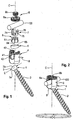
- a polyaxial bone anchoring device includes a bone anchoring element 1 in the form of a bone screw having a threaded shank 2 and a head 3.
- the head 3 typically has a spherically-shaped outer surface portion 3a and a recess 3b at its free end for engagement with a driver or tool.
- the spherically-shaped outer surface portion 3a of the head includes a portion with a greatest outer diameter E of the head 3.
- the head 3 may be held in a receiving part 4 that couples the bone anchoring element 1 to a stabilization rod 100.
- a sleeve-like insert piece 5 and a cap member 6 that is seated in the sleeve-like insert piece 5 and that exerts pressure onto the head 3 are arranged. Furthermore, a separate rod receiving element 7 is provided for receiving the rod 100 and for transmitting pressure onto the cap member 6.
- a locking device 8 comprising a first locking element 8a and a second locking element 8b is also provided for securing and fixing the rod 100 in the receiving part 4.
- the receiving part 4 has a first end forming in the position of ordinary use a top end 4a and a second end forming in the ordinary position of use a bottom end 4b, a central axis C and a passage 41 extending from the top end 4a in the direction of the bottom end 4b.
- a substantially U-shaped recess 42 Adjacent to the top end 4a, a substantially U-shaped recess 42 is provided that forms a channel for receiving the rod 100.
- two free legs are formed which are provided with an internal thread 43 for cooperating with the first locking element 8a.
- the passage 41 that may be a coaxial bore opens into an accommodation space 44 provided in a lower part of the receiving part 4 (e.g., nearer to the bottom end 4b).
- the accommodation space 44 has a lower opening 45 at the bottom end 4b of the receiving part 4.
- the accommodation space 44 further includes a seat portion 46 near the bottom end 4b of the receiving part 4 in that the sleeve-like insert piece 5 may be seated.
- the seat portion 46 has a spherical shape, in order to provide a socket for a ball-and-socket joint that is formed by the sleeve-like insert piece 5 and the receiving part 4.
- the seat portion 46 can also be tapered, or can have various other shapes that can be used to realize a ball-and-socket joint.
- An inner diameter of the lower opening 45 is smaller than an inner diameter of a middle portion of the accommodation space 44.
- an inner diameter of the passage 41 does not need to be constant between the top end 4a and the accommodation space 44.
- the passage 41 may have different portions with different diameters.
- two opposed recesses 47a, 47b are formed in the inner wall of the passage 41 and the accommodation space 44.
- the recesses 47a, 47b are aligned with the U-shaped recess 42 and extend from a bottom of the U-shaped recess 42 into the accommodation space 44.
- the size of the recesses 47a, 47b are such that the sleeve-like insert piece 5 can be inserted from the top end 4a in a 90° tilted position, i.e. the widths of the recesses 47a, 47b are greater than a height of the sleeve-like insert piece 5 in its axial direction.
- the distance between the bottom of the recesses 47a, 4b in a direction transverse to the central axis C is greater than a maximum outer diameter of the sleeve-like insert piece.
- the recesses 47a, 4b extend into the accommodation space 44 to such an extent that tilting of the insert piece 5 into the seat portion 46 is possible.
- the receiving part 4 has at least one pin hole 48 for receiving a pin 9 that forms a retaining element to retain the pieces within the receiving part 4.
- the pin hole 48 may be arranged at 90° relative to the channel axis of the U-shaped recess 42.
- a second pin (not shown) may be provided on, for example, an opposite side of the receiving part 4.
- an undercut portion 49 is provided, the upper edge 49a of which forms a stop for the rod receiving element 7 as described more in detail below.
- the undercut portion 49 thus forms two ringsegment shaped grooves with a depth that is larger than an inner diameter of the passage 41 between the internal thread 43 and the accommodation space 44.
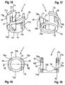
- the sleeve-like insert piece 5 is shown in more detail in Figs. 8 to 11 .
- the sleeve-like insert piece 5 has an upper edge 5a and a lower edge 5b. Between the upper edge 5a and the lower edge 5b the sleeve-like insert piece may have a spherically-shaped outer surface portion 51. A largest outer diameter of the sleeve-like insert piece 5 is greater than the inner diameter of the lower opening 45 of the receiving part 4. Hence, the sleeve-like insert piece 5 cannot escape through the lower opening 45 when it is seated in the receiving part 4.
- the dimension or shape of the outer spherical surface portion 51 corresponds to that of the spherically-shaped seat portion 46 of the receiving part 4 in such a way that the sleeve-like insert piece 5 can pivot and rotate in the receiving part 4 when the insert piece 5 is seated in the seat portion 46.
- the sleeve-like insert piece 5 rests in the seat portion 46, such that its central axis 5c is coaxial with the central axis C of the receiving part 4, the lower edge 5b projects out of the lower opening 45 of the receiving part.
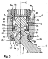
- the sleeve-like insert piece 5 is pivoted or angled in the receiving part 4, as shown, for example, in Fig. 3 , at least a portion of the lower edge 5b still projects out of the lower opening 45.
- the sleeve-like insert piece 5 is hollow and has a central portion 52 that is spherically-shaped with a radius corresponding to a radius of a spherically-shaped outer surface portion of the cap member which is described below. A lower end of the central portion 52 forms a shoulder 53.
- An inner diameter of the shoulder 53 is smaller than a largest outer diameter of the spherically-shaped portion of the cap member when the head 3 is inserted into the cap member 6, so that the cap member 6 with inserted head 3 can rotate and pivot in the central spherical portion 52 of the sleeve-like insert piece 5, similar to a ball-and-socket joint, and the head 3 cannot be removed through the bottom end 4b of the receiving part when the spherical surfaces of the sleeve-like insert piece 5 and the cap member 6 are engaged.
- a tapered portion 54 is provided that widens in the direction of the lower edge 5b to allow angulation of the bone anchoring element 1 until the shank 2 comes into contact with the lower edge 5b.
- a tapered portion 55 is provided which widens in the direction of the upper edge 5a.
- An inner diameter of the tapered portion 55 and of a transition between the tapered portion 55 and the spherical portion 52 are greater than a largest outer diameter of the flexible portion of the cap member, so that the cap member 6 with inserted head 3 can move from the upper edge 5a into the spherical central portion 52 of the sleeve-like insert piece.
- Center points of the spherical central portion 52 and the outer spherical portion 51 may be the same in an axial direction. However, the center point of the central spherical portion 52 may also be shifted in the direction toward the lower edge 5b relative to the center point of the outer spherical portion 51. This may increase the range of angulation of the bone anchoring element 1 further.
- a height of the sleeve-like insert piece 5 in an axial direction is less than a height of the head 3 in an axial direction, such that when the head 3 is inserted into the cap member 6 and the cap member 6 is inserted into the sleeve-like insert piece 5, as shown in Fig. 3 and for example in Fig. 25 , a portion of the spherical outer surface 3a of the head 3 may still project from the upper edge 5a of the sleeve-like insert piece 5.
- the cap member 6 will be described referring to Figs. 1 to 3 and 12 to 15 .
- the cap member 6 is a pressure member that is configured to clamp the head 3 upon compression of a portion of the cap member 6. It comprises a first or upper end 6a and an opposite second or lower end 6b and a central axis 6c extending through the upper end 6a and the lower end 6b.
- the central axis 6c of the cap member is coaxial with the central axis C of the receiving part.
- the cap member 6 Adjacent to the lower end 6b, the cap member 6 comprises a first portion 61 that is flexible in such a way that it can be compressed and expanded in a radial direction.
- the first portion 61 has a hollow interior chamber 62 that is substantially spherically-shaped to clamp the spherical head 3 therein.
- an opening 63 is provided for inserting the head 3 through the opening 63 into the hollow interior chamber 62.
- the outer surface of the first portion 61 comprises a spherically-shaped portion that is configured to cooperate with the central spherically-shaped portion 52 of the sleeve-like insert piece 5.
- the shape of the first portion 61 resembles that of a cap that is to be placed on the head 3.
- a plurality of slits 64 extend from the lower end 6b through the first portion 61 in a direction toward the upper end 6a.
- the slits 64 are open toward the lower end 6b and closed at the opposite end where they may have an enlarged, area 64a to facilitate compression or expansion of the first portion 61.
- the enlarged area 64a may have a circular shape.
- the number and dimensions of the slits 64 are such that the wall of the first portion 61 is flexible enough to snap onto the head 3 when the head 3 is inserted.
- the size of the first portion 61 in the axial direction is such that when the head 3 is inserted fully into the cap member 6, the lower end 6b of the cap member 6 extends beyond a portion of the head 3 that includes the largest diameter E of the head 3 in the direction toward the shank 2.
- a maximum outer diameter of the first portion 61 of the cap member 6 in the neutral position of the first portion 61 i.e. when it is neither compressed nor expanded, is smaller than an inner diameter of the accommodation space 44 and also smaller than an inner diameter of the upper tapered portion 55 of the sleeve-like insert piece 5. Therefore, it is possible to insert the head 3 through the opening 63 into the cap member 6 when the cap member is placed in the receiving part 4 and its first portion 61 extends into the accommodation space 44 and partially into the sleeve-like insert piece 5.
- the dimension of the cap member 6 relative to the head 3 is such that when the head 3 is inserted through the lower opening 63 into the hollow interior chamber 62 of the cap member 6 it is held therein by friction. That means, an angular position of the bone anchoring element relative to the cap member 6 can be adjusted by applying a force that overcomes the friction force.
- the cap member 6 further has a lower slanted edge portion 65 at its lower end 6b where the cap member 6 is shorter in an axial direction over a particular range of angles around the central axis 6c compared to the opposite side.
- the slanted edge portion 65 may be achieved by cutting away a portion of the cap member 6 in an inclined cut. By means of this, the bone anchoring element abuts with its shank 2 against the lower edge 6b of the cap member at a larger angle in the direction of the slanted lower edge portion 65 as compared to the opposite direction.
- An enlarged pivot angle can be achieved by other means also, for example, instead of the slanted lower edge portion 65, a recess can be provided that allows the shank 2 to extend more outwardly as in an opposite direction.
- the cap member 6 further comprises adjacent to the flexible first portion 61 a non-flexible second portion 66 that has a substantially cylindrical outer shape with an outer diameter that is only slightly smaller than an inner diameter of the passage 41 in the receiving part 4 so that the second portion 66 can move in the passage 41. Due to the cylindrical shape, the second portion 66 is rotatable in the receiving part 4.
- the cap member 6 additionally comprises a coaxial bore 67 that extends from the upper end 6a into the hollow interior chamber 62. As can be seen in particular in Fig. 14 , by means of the coaxial recess 67 a ring-shaped flat upper surface is formed at the upper end 6a. This surface serves for cooperating with a lower surface of the rod receiving element 7 to be described below.
- a single recess 68 is formed that serves as an indication mark for indicating the position of the slanted lower edge portion 65 that provides the enlarged pivot angle.
- the recess 68 is aligned with the slanted lower edge portion 65 in a circumferential direction so that even if in atop view the position of the slanted lower edge portion 65 cannot be seen, the recess 68 indicates the position of the slanted lower edge portion 65.
- the recess 68 may be used for cooperation with a corresponding tool that engages the cap member 6, for example through the coaxial bore 67 and that has a corresponding indication mark, such as a projection, for example, that indicates a specific orientation in circumferential direction around the central axis 6c. Hence, by rotating the cap member 6 the orientation of the enlarged pivot angle can be adjusted to a desired orientation.
- the rod receiving element 7 is a part that is separate from the cap member 6. It is a substantially cylindrical part that comprises a first or upper end 7a with a free end surface and an opposite second or lower end 7b with a free end surface. Adjacent to the first end there is a substantially rectangular recess 71 that cuts out such a portion of the cylinder that two free upstanding legs 71a, 71b remain. Adjacent to the lower end 7b there is an opening 72, preferably a circular opening that extends through the rod receiving element 7 into the recess 71. An inner diameter of the opening 72 is greater than the inner diameter of the coaxial bore 67 of the cap member 6 so that the end surface of the lower end 7b is configured to fully contact the upper end surface of the upper end 6a of the cap member 6.
- two concave cylinder-segment shaped rod supporting projections 73a, 73b are provided on both sides of the opening 72.
- the radius of the concave portions 73a, 73b is preferably selected such that it is adapted to the radius of the specific rod to be used.
- the rod supporting projections 73a, 73b may be separated from the legs 71a, 71b by a groove 74 on each side of the projections.
- the width of the recess 71 is such that the rod 100 can be received in the recess 71.
- a height of the legs 71, 71b is such that the upper end 7a is located above the upper rod surface when the rod 100 is placed into the channel 71 and rests on the rod supporting projections 73a, 73b as shown in Fig. 3 .
- An outer diameter of the rod receiving element 7 is only slightly smaller than an inner diameter of the passage 41 of the receiving part 4 so that the rod receiving element 7 can move in the passage 41 to some extent and is guided therein.
- the rod receiving element 7 further comprises at each leg 71a, 71b an elongate recess 75 that extends substantially from the bottom of the recess 71 to a distance from the first end 7a.
- the recesses 75 extend completely through each leg 71a, 71b in a radial direction. They have such a width that the pin 9 can be accommodated therein.
- a bottom end 75a of each elongate recess 75 forms a stop for the pin 9 that extends into one recess. The stop prevents the rod receiving element 7 from escaping through the first end 4a of the receiving part 4 when the cap member 6 is in an insertion position.
- the recesses 75 may serve with the at least one pin 9 as a securing device to maintain the alignment between the recess 42 of the receiving part 4 and the channel 71 of the rod receiving element 7.
- the pin 9 forms a first retaining element that secures the pre-assembled receiving part 4 with the sleeve-like insert piece 5, the cap member 6 and the rod receiving element 7 against loss of in particular the rod receiving element 7 and/or the cap member 6.
- Providing two recesses 75, one on each side, allows to insert the rod receiving element 7 into the receiving part 4 in two orientations that are offset by 180°. This is convenient, for example, if only one pin 9 is used.
- the rod receiving element 7 has on each leg 71a, 71 b, at a position above the recesses 75, a circumferentially extending projection 76 with a flat upper surface 76a and an inclined lower surface 76b.
- a maximum outer diameter of the projections 76 is slightly larger than an inner diameter of the internal thread 73.
- the projection 76 is configured to enter into the undercut portion 49 and the upper edge 49a of the undercut portion 49 forms a second retaining element that cooperates with the flat upper surface 76a of the projection 76 to prevent upward movement of the rod receiving element 7. Furthermore, on each leg 71, 71b, a longitudinally extending cylinder segment-shaped recess 77 is provided that extends from the bottom of the recess 71 to the first end 7a.
- the bone anchoring device as a whole or in part is made of a bio-compatible material, such as a bio-compatible metal or a metal alloy, for example titanium, stainless steel, a nickel-titanium alloy, for example, Nitinol, or of a bio-compatible plastic material, such as, for example, from the group of polyaryletherketones, for example polyetheretherketone (PEEK).
- a bio-compatible material such as a bio-compatible metal or a metal alloy, for example titanium, stainless steel, a nickel-titanium alloy, for example, Nitinol
- a bio-compatible plastic material such as, for example, from the group of polyaryletherketones, for example polyetheretherketone (PEEK).
- the receiving part may be pre-assembled with the sleeve-like insert piece 5 and the cap member 6 as well as the rod receiving element 7 in the following manner.
- the sleeve-like insert piece 5 is inserted from the top end 4a into the receiving part in a tilted orientation, i.e. the central axis 5c of the sleeve is perpendicular to the central axis C of the receiving part 4.
- the sleeve-like insert piece 5 is furthermore inserted in such an orientation that it extends into the recesses 47a, 47b of the receiving part.
- the rod receiving element 7 is inserted from the upper end 4a into the passage 41 such that the recess 71 for receiving the rod 100 is aligned with the recess 42 of the receiving part 4. Subsequently, the pin 9 is inserted into the pin hole 48 until it engages the elongate recess 75 at one of the legs 71b of the rod receiving element 7. By means of this the rotational position of the rod receiving element 7 is secured and the rod receiving element 7 is secured against escaping through the top end 4a of the receiving part 4.
- the orientation in which the enlarged pivot angle is provided can be adjusted by rotating the cap member once it has been inserted into the receiving part 4 or after inserting the head into the cap member.
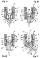
- the circumferential projection 76 on the legs 71a, 71b of the rod receiving element 7 is in a position above the undercut 49 when the cap member 6 is in an insertion position for the head 3, as shown in Figs. 23 and 24 .
- the bone anchoring element 1 is connected to the receiving part 4.
- the bone anchoring element 1 has been already inserted into a bone part or a vertebra and the receiving part 4 is mounted onto the head 3 of the bone anchoring element in situ at the operation site or the bone anchoring element is connected beforehand to the receiving part 4 and thereafter inserted into the bone or vertebra.
- the head 3 is inserted through the sleeve-like insert piece 5 into the interior chamber 62 of the cap member 6.
- the cap member 6 is moved upward toward the upper end 4a of the receiving part 4 until it abuts with its upper end 6a against the lower end 7b of the rod receiving element.
- the rod receiving element 7 is moved downward and shifts the cap member 6 with the inserted head 3 into the central spherical portion 52 of the sleeve-like insert piece 5.
- the rod receiving element 7 is pressed downward, until the upper surface 76a of the projection 76 snaps into the undercut 49. In this position, the lower edge 49a of the undercut 49 retains the rod receiving element 7 so that it cannot move upward again.
- the first portion 61 of the cap member 6 is compressed by the sleeve-like insert piece 5 to such an extent, that the lower opening of the sleeve-like insert piece 5 is narrowed so that the head 3 cannot be removed from the receiving part.
- the receiving part 4 can be manually or in another way pivoted relative to the bone anchoring element while the relative angular position of the bone anchoring element 1 to the receiving part 4 is maintained in a preliminary manner.
- the head 3 In the pre-locking position of the cap member 6, the head 3 is pivotable relative to the receiving part 4 in all directions.
- the shank 2 of the bone anchoring element 1 abuts against the lower portion 54 of the sleeve-like insert piece 5.
- the sleeve-like insert piece 5 pivots in the seat 46 of the accommodation space 44 of the receiving part 4 as shown in Fig. 27 .
- the bone anchoring element 1 can pivot to the side comprising the slanted lower edge portion 65 at a greater angle than in an opposite direction.
- the enlarged pivot angle ⁇ defined as the maximum angle that the shank axis S can include with the central axis C of the receiving part 4 may be equal to or greater than 40° measured from the central axis C.
- a portion of the head 3 may extend into the coaxial bore 67 of the cap member.
- the rod 100 is inserted into the receiving part and the rod receiving element 7 and the locking element 8 is inserted into the receiving part 4.
- the first locking element 8a acts onto the upper end 7a of the legs 71a, 71b of the rod receiving element 7. If the first locking element 8a is tightened, the pressure is transmitted through the rod receiving element 7 and the cap member 6 onto the head 3 and the sleeve-like insert piece 5. By means of this, the sleeve-like insert piece 5 is pressed into the seat 46 of the accommodation space 44.
- the head 3 in the cap member 6 and the sleeve-like insert piece 5 in the accommodation space 44 are both locked so that the position of the bone anchoring element 1 relative to the receiving part is fixed. Tightening of the second locking element 8b fixes the rod 100.
- the construct is more robust and can take up higher locking forces compared to a device with a flexible sleeve or a flexible cap member only.
- a single part locking device (not shown) can be used that may consist of, for example, a set screw with a central projection that acts onto the rod only.
- the pressure exerted by the single part locking device is transferred to the rod 100 onto the rod receiving element 7 and the cap member 6.
- the rod 100 and the head 3 can be fixed simultaneously.
- Other kinds of locking devices may be contemplated, for example, a sequential locking device that comprises a single drive portion only and that fixes the head and the rod sequentially.
- At least two bone anchoring elements are anchored in a bone or in adjacent vertebrae and connected by a rod.
- surgeon or any other personnel can select a desired bone anchoring element and combine it with the pre-assembled receiving part with sleeve-like insert piece, cap member and rod receiving element.
- the design of the bone anchoring device allows the selection of an appropriate bone anchoring element in terms of diameter, length, and other features.
- a suitable locking device may be selected.
- a modular system is provided which includes various elements which individually can be chosen and adapted.
- the cap member 6' differs from the cap member 6 in the design of the slits. Instead of a plurality of longitudinal slits, one or more substantially horizontally extending slits are provided.
- the cap member 6' has a first substantially vertical slit 640a that extends from the lower edge 6b and opens into a substantially horizontal slit 640b that extends around the central portion in a slightly slanted manner until a first end (not shown) on one side and a second end 640d at a second side.
- the substantially vertical slit 640a may be preferably at the side where the slanted lower edge 65 is provided.
- cap member 6' All other parts of the cap member 6' are the same and have the same reference numerals and the description thereof will not be repeated.
- the receiving part and the rod receiving element are the same as for the first embodiment.
- an insertion force that is necessary to insert the head into the cap member 6' may be reduced compared to the cap member 6 of the first embodiment while the holding force in the pre-locking position may be the same or similar for both cap members.
- the receiving part is not limited to the exact shape as shown.
- the recess 42 does not have to have an exact U-shape.
- the retaining elements can be realized otherwise, for example through spring portions, snap rings or other constructs that prevent movement of the rod receiving element and the receiving part relative to each other.
- the head 3 and correspondingly the interior chamber 62 of the cap member 6 can have another shape.
- two opposite flattened portions may be present that render the pivot connection monoplanar.
- anchoring elements can be used and combined witch the receiving part.
- These anchoring elements may be, for example, screws with different length; screws with different diameters, cannulated screws, screws with different thread forms, nails, hooks, etc.
- the head and the shaft may also be separate parts that are connectable to each other.
- rods can be used. While rods with a smooth surface are shown, roughened rods or rods having a structure may be used. The rods may also be flexible rods.
Landscapes
- Health & Medical Sciences (AREA)
- Orthopedic Medicine & Surgery (AREA)
- Life Sciences & Earth Sciences (AREA)
- Neurology (AREA)
- Surgery (AREA)
- Heart & Thoracic Surgery (AREA)
- Engineering & Computer Science (AREA)
- Biomedical Technology (AREA)
- Nuclear Medicine, Radiotherapy & Molecular Imaging (AREA)
- Medical Informatics (AREA)
- Molecular Biology (AREA)
- Animal Behavior & Ethology (AREA)
- General Health & Medical Sciences (AREA)
- Public Health (AREA)
- Veterinary Medicine (AREA)
- Surgical Instruments (AREA)
Claims (16)
- Dispositif polyaxial d'ancrage osseux, comprenant :un élément d'ancrage (1) comportant une tige (2) pour l'ancrage dans l'os et une tête (3), la tête comprenant une partie de surface extérieure (3a) de forme sphérique ;une pièce réceptrice (4) configurée pour être raccordée en pivotement à ladite tête (3), la pièce réceptrice comportant une première extrémité (4a), une seconde extrémité (4b), un axe central (C) traversant la première extrémité (4a) et la seconde extrémité (4b), un canal (42) pour recevoir une tige (100), un espace de logement (44) pour loger la tête (3), l'espace de logement (44) comportant une ouverture inférieure (45) à la seconde extrémité (4b) et un passage coaxial (41) partant de la première extrémité (4a) pour entrer dans l'espace de logement (44),un élément de capuchon (6, 6') qui est disposé au moins en partie dans l'espace de logement (44), l'élément de capuchon (6, 6') comportant une première partie (61) qui est configurée pour être mise en place au moins en partie autour de la tête (3), dans lequel la première partie (61) peut s'agrandir dans l'espace de logement (44) pour permettre l'introduction de la tête (3) et se comprimer pour exercer une pression sur la tête (3) ;une pièce d'insertion (5) en forme de manchon configurée pour être mise en place au moins partiellement autour de la première partie (61) de l'élément de capuchon (6, 6'), dans lequel la pièce d'insertion (5) en forme de manchon comprend une partie de surface extérieure (51) de forme sphérique et est configurée pour pivoter dans la pièce réceptrice (4).
- Dispositif polyaxial d'ancrage osseux selon la revendication 1, dans lequel la première partie (61) de l'élément de capuchon (6, 6') comprend un espace intérieur creux (62) avec une partie de paroi intérieure en forme de sphère pour y accueillir au moins une partie de la tête (3) et une ouverture inférieure (63) pour introduire la tête (3) et dans lequel l'ouverture inférieure (63) comprend un bord englobant (6b) ayant une partie (65) qui est configurée pour permettre à la tête (3) de pivoter d'un angle plus grand dans une direction que dans une autre direction.
- Dispositif polyaxial d'ancrage osseux selon la revendication 2, dans lequel l'élément de capuchon (6, 6') comprend un repère (68) qui est configuré pour indiquer l'orientation de la partie (65) du bord englobant (6b) permettant l'angle de pivotement plus grand quand l'élément de capuchon (6, 6') est introduit dans la pièce réceptrice (4).
- Dispositif polyaxial d'ancrage osseux selon l'une quelconque des revendications 1 à 3, dans lequel la dimension de l'élément de capuchon (6, 6') est telle que la tête (3) est maintenue dans l'élément de capuchon (6, 6') par frottement une fois que la tête (3) est introduite dans la première partie (61) de l'élément de capuchon (6, 6').
- Dispositif polyaxial d'ancrage osseux selon l'une quelconque des revendications 1 à 4, dans lequel l'élément de capuchon (6, 6') peut tourner dans la pièce réceptrice (4) quand la première partie (61) n'est pas comprimée.
- Dispositif polyaxial d'ancrage osseux selon l'une quelconque des revendications 1 à 5, dans lequel l'élément de capuchon (6, 6') comprend une seconde partie (66) qui comporte une surface en forme d'anneau (6a) sensiblement plate tournée vers la première extrémité (4a) de la pièce réceptrice (4).
- Dispositif polyaxial d'ancrage osseux selon l'une quelconque des revendications 1 à 6, dans lequel la pièce d'insertion (5) en forme de manchon comprend un bord inférieur (5b) qui dépasse l'ouverture inférieure (45) de l'espace de logement (44) dans la direction s'éloignant de la pièce réceptrice (4) quand la pièce d'insertion (5) est assise dans la pièce réceptrice dans une position dans laquelle l'axe central (5c) de la pièce d'insertion (5) est coaxial avec l'axe central (C) de la pièce réceptrice (4).
- Dispositif polyaxial d'ancrage osseux selon l'une quelconque des revendications 1 à 7, dans lequel la pièce d'insertion (5) en forme de manchon comporte une ouverture (55) ayant un diamètre qui est supérieur ou égal au diamètre maximal de la première partie (61) de l'élément de capuchon quand la tête (3) est introduite dans l'élément de capuchon (6, 6').
- Dispositif polyaxial d'ancrage osseux selon l'une quelconque des revendications 1 à 8, dans lequel la pièce d'insertion (5) en forme de manchon comporte une partie de surface intérieure (52) de forme sphérique qui est configurée pour coopérer avec une partie de surface extérieure de forme sphérique de la première partie (61) de l'élément de capuchon (6, 6') de telle sorte que la pièce d'insertion (5) puisse pivoter par rapport à l'élément de capuchon (6, 6') quand la tête (3) est introduite dans la première partie (61) de l'élément de capuchon.
- Dispositif polyaxial d'ancrage osseux selon l'une quelconque des revendications 1 à 9, dans lequel quand la tête (3) est introduite dans l'élément de capuchon (6, 6'), la pièce d'insertion (5) peut pivoter par rapport à l'axe central (C) de la pièce réceptrice (4) et par rapport à l'axe longitudinal (S) de l'élément d'ancrage (1), et dans lequel l'élément d'ancrage (1) peut pivoter par rapport à l'axe central (6c) de l'élément de capuchon (6, 6'), et dans lequel on peut verrouiller l'élément d'ancrage (1) et la pièce d'insertion (5) sous des angles respectifs avec l'axe central (C) de la pièce réceptrice (4) en exerçant une pression avec l'élément de capuchon (6, 6') sur la tête (3) et sur la pièce d'insertion (5).
- Dispositif polyaxial d'ancrage osseux selon l'une quelconque des revendications 1 à 10, comprenant en outre une partie (7) de réception de tige placée dans le passage (41) entre l'élément de capuchon (6, 6') et la première extrémité (4a) de la pièce réceptrice (4).
- Dispositif polyaxial d'ancrage osseux selon la revendication 11, dans lequel la partie (7) de réception de tige est configurée pour transmettre une force de pression sur la première partie (61) de l'élément de capuchon (6, 6').
- Dispositif polyaxial d'ancrage osseux selon la revendication 11 ou 12, dans lequel la partie (7) de réception de tige comprend un canal (71) pour recevoir la tige (100) et dans lequel on trouve un premier élément de rétention (9) qui agit entre la partie (7) de réception de tige et la pièce réceptrice (4) pour empêcher la partie (7) de réception de tige de s'échapper par la première extrémité (4a) de la pièce réceptrice (4) et qui est de préférence configuré pour maintenir alignés le canal (71) pour recevoir la tige de la partie (7) de réception de tige et le canal (42) de la pièce réceptrice (4).
- Dispositif polyaxial d'ancrage osseux selon l'une quelconque des revendications 11 à 13, dans lequel on trouve un second élément de rétention (49, 76a) qui agit entre la partie (7) de réception de tige et la pièce réceptrice (4) pour maintenir la première partie (61) de l'élément de capuchon (6, 6') par rapport à la pièce d'insertion (5) en forme de manchon dans une position propre à empêcher la tête (3) de sortir de l'élément de capuchon (6, 6').
- Dispositif polyaxial d'ancrage osseux selon l'une quelconque des revendications 11 à 14, dans lequel le canal (71) pour recevoir la tige (100) de la partie (7) de réception de tige comprend des parois latérales qui s'étendent au-dessus de la surface supérieure de la tige (100) introduite.
- Dispositif polyaxial d'ancrage osseux selon l'une quelconque des revendications 11 à 15, dans lequel la partie (7) de réception de tige est une pièce séparée qui comprend une partie de surface inférieure (7b) tournée vers la partie de surface supérieure (6a) de l'élément de capuchon et coopérant avec elle pour transmettre une pression sur l'élément de capuchon (6, 6').
Priority Applications (6)
| Application Number | Priority Date | Filing Date | Title |
|---|---|---|---|
| EP13192978.8A EP2873383B1 (fr) | 2013-11-14 | 2013-11-14 | Dispositif d'ancrage d'os polyaxial doté d'un angle de pivot élargi |
| CN201410645258.7A CN104622556A (zh) | 2013-11-14 | 2014-11-11 | 具有扩大枢转角的多轴骨锚固装置 |
| TW103138971A TW201517862A (zh) | 2013-11-14 | 2014-11-11 | 多軸式骨骼固定裝置 |
| JP2014228713A JP2015093200A (ja) | 2013-11-14 | 2014-11-11 | 多軸骨固定装置 |
| US14/539,461 US9492204B2 (en) | 2013-11-14 | 2014-11-12 | Polyaxial bone anchoring device with enlarged pivot angle |
| KR1020140158303A KR20150056068A (ko) | 2013-11-14 | 2014-11-13 | 확대된 피봇 각을 지닌 다축 뼈 고정 장치 |
Applications Claiming Priority (1)
| Application Number | Priority Date | Filing Date | Title |
|---|---|---|---|
| EP13192978.8A EP2873383B1 (fr) | 2013-11-14 | 2013-11-14 | Dispositif d'ancrage d'os polyaxial doté d'un angle de pivot élargi |
Publications (2)
| Publication Number | Publication Date |
|---|---|
| EP2873383A1 EP2873383A1 (fr) | 2015-05-20 |
| EP2873383B1 true EP2873383B1 (fr) | 2016-10-19 |
Family
ID=49584638
Family Applications (1)
| Application Number | Title | Priority Date | Filing Date |
|---|---|---|---|
| EP13192978.8A Active EP2873383B1 (fr) | 2013-11-14 | 2013-11-14 | Dispositif d'ancrage d'os polyaxial doté d'un angle de pivot élargi |
Country Status (6)
| Country | Link |
|---|---|
| US (1) | US9492204B2 (fr) |
| EP (1) | EP2873383B1 (fr) |
| JP (1) | JP2015093200A (fr) |
| KR (1) | KR20150056068A (fr) |
| CN (1) | CN104622556A (fr) |
| TW (1) | TW201517862A (fr) |
Families Citing this family (45)
| Publication number | Priority date | Publication date | Assignee | Title |
|---|---|---|---|---|
| US8444681B2 (en) | 2009-06-15 | 2013-05-21 | Roger P. Jackson | Polyaxial bone anchor with pop-on shank, friction fit retainer and winged insert |
| JP2012529969A (ja) * | 2008-08-01 | 2012-11-29 | ロジャー・ピー・ジャクソン | スリーブ付き張力付与りコードを備える長手方向接続部材 |
| US11229457B2 (en) | 2009-06-15 | 2022-01-25 | Roger P. Jackson | Pivotal bone anchor assembly with insert tool deployment |
| US9044272B2 (en) * | 2009-11-09 | 2015-06-02 | Ebi, Llc | Multiplanar bone anchor system |
| US20230404629A1 (en) | 2010-05-14 | 2023-12-21 | Roger P. Jackson | Pivotal bone anchor assembly and method for use thereof |
| JP5865479B2 (ja) * | 2011-03-24 | 2016-02-17 | ロジャー・ピー・ジャクソン | 複合関節とポップ装着式シャンクとを有する多軸の骨アンカー |
| US9993269B2 (en) * | 2011-07-15 | 2018-06-12 | Globus Medical, Inc. | Orthopedic fixation devices and methods of installation thereof |
| EP2606841B1 (fr) * | 2011-12-23 | 2016-03-09 | Biedermann Technologies GmbH & Co. KG | Dispositif polyaxial d'ancrage osseux |
| WO2013106217A1 (fr) | 2012-01-10 | 2013-07-18 | Jackson, Roger, P. | Fermetures à départs multiples pour implants ouverts |
| EP2764840B1 (fr) | 2013-02-11 | 2017-05-03 | Biedermann Technologies GmbH & Co. KG | Ensemble de couplage d'une tige à un élément d'ancrage osseux et dispositif d'ancrage osseux avec un tel ensemble de couplage |
| US9498255B2 (en) * | 2013-12-31 | 2016-11-22 | Blackstone Medical, Inc. | Translational pedicle screw systems |
| ES2611014T3 (es) * | 2014-01-13 | 2017-05-04 | Biedermann Technologies Gmbh & Co. Kg | Conjunto de acoplamiento para acoplar una varilla a un elemento de anclaje óseo, y dispositivo de anclaje óseo poliaxial |
| US10188432B2 (en) * | 2014-06-04 | 2019-01-29 | Roger P. Jackson | Snap-on multi-planar and mono-planar receiver assemblies having integral and multi-part multipurpose positioners for pivoting and non-pivoting retainers |
| US10064658B2 (en) | 2014-06-04 | 2018-09-04 | Roger P. Jackson | Polyaxial bone anchor with insert guides |
| US11219471B2 (en) * | 2014-10-21 | 2022-01-11 | Roger P. Jackson | Pivotal bone anchor receiver having an insert with post-placement tool deployment |
| US10543021B2 (en) | 2014-10-21 | 2020-01-28 | Roger P. Jackson | Pivotal bone anchor assembly having an open ring positioner for a retainer |
| EP3031415B1 (fr) | 2014-12-10 | 2018-10-31 | Biedermann Technologies GmbH & Co. KG | Ensemble d'accouplement et dispositif d'ancrage osseux polyaxial comprenant celui-ci |
| US9707013B2 (en) * | 2015-04-30 | 2017-07-18 | Warsaw Orthopedic, Inc. | Spinal implant system and methods of use |
| EP3092963B1 (fr) * | 2015-05-12 | 2017-07-12 | Biedermann Technologies GmbH & Co. KG | Dispositif de couplage d'une tige à un élément d'ancrage osseux et dispositif d'ancrage osseux avec un tel dispositif |
| US10799226B2 (en) * | 2015-07-15 | 2020-10-13 | Warsaw Orthopedic, Inc. | Surgical adaptor and method |
| US9968378B1 (en) * | 2015-07-22 | 2018-05-15 | University Of South Florida | Adaptation sphere saddle |
| US10918418B2 (en) | 2015-08-21 | 2021-02-16 | Kyocera Corporation | Spinal implant |
| US10874438B2 (en) | 2016-07-13 | 2020-12-29 | Medos International Sarl | Bone anchor assemblies and related instrumentation |
| US10568667B2 (en) * | 2016-07-13 | 2020-02-25 | Medos International Sàrl | Bone anchor assemblies and related instrumentation |
| KR101868694B1 (ko) * | 2016-10-21 | 2018-06-18 | 주식회사 지비에스커먼웰스 | 뼈 고정 스크류 장치 및 그 체결방법 |
| US10368916B2 (en) * | 2017-01-11 | 2019-08-06 | Warsaw Orthopedic, Inc. | Spinal implant system and methods of use |
| US10835291B2 (en) * | 2017-01-12 | 2020-11-17 | Warsaw Orthopedic, Inc. | Spinal implant system and methods of use |
| US11096727B2 (en) * | 2017-01-18 | 2021-08-24 | K2M, Inc. | Modular spinal fixation device |
| US11419639B2 (en) | 2017-03-30 | 2022-08-23 | K2M, Inc. | Modular offset screw |
| WO2018183489A1 (fr) | 2017-03-30 | 2018-10-04 | K2M, Inc. | Vis modulaire |
| EP3600095B1 (fr) | 2017-03-30 | 2023-03-15 | K2M, Inc. | Appareil d'ancrage osseux |
| US10610265B1 (en) * | 2017-07-31 | 2020-04-07 | K2M, Inc. | Polyaxial bone screw with increased angulation |
| US10285738B1 (en) * | 2017-12-12 | 2019-05-14 | Spinal Llc | Polyaxial ball and socket fastener with spot welded blocking ring |
| EP3536271B1 (fr) * | 2018-03-06 | 2022-05-04 | Biedermann Technologies GmbH & Co. KG | Dispositif d'ancrage osseux polyaxial et système d'un instrument et dispositif d'ancrage osseux polyaxial |
| WO2020056385A1 (fr) | 2018-09-13 | 2020-03-19 | Jackson Roger P | Ensemble d'ancrage osseux pivotant à récepteur modulaire et tête de tige universelle |
| WO2020102787A1 (fr) | 2018-11-16 | 2020-05-22 | Surber, James L. | Ensemble ancrage osseux pivotant ayant un insert de douille de serrage déployable avec bague de pression interne |
| EP3937832B1 (fr) * | 2019-03-13 | 2024-05-01 | Straumann Holding AG | Clé dynamométrique médico-dentaire |
| WO2021061970A1 (fr) * | 2019-09-24 | 2021-04-01 | Corelink, Llc | Vis à os polyaxiale |
| WO2021127251A1 (fr) | 2019-12-17 | 2021-06-24 | Jackson Roger P | Ensemble ancrage osseux avec dispositif de retenue d'anneau fermé et bague d'encliquetage interne |
| EP3878386B1 (fr) * | 2020-03-12 | 2023-08-30 | Biedermann Technologies GmbH & Co. KG | Dispositif de couplage à utiliser avec un élément d'ancrage osseux et dispositif d'ancrage osseux comportant un tel dispositif |
| USD956233S1 (en) * | 2020-04-24 | 2022-06-28 | Solco Biomedical Co., Ltd. | Cervical screw |
| WO2022108875A1 (fr) | 2020-11-19 | 2022-05-27 | K2M, Inc. | Ensemble tête modulaire pour fixation rachidienne |
| US11751915B2 (en) | 2021-07-09 | 2023-09-12 | Roger P. Jackson | Modular spinal fixation system with bottom-loaded universal shank heads |
| EP4201348A1 (fr) * | 2021-12-23 | 2023-06-28 | K2M, Inc. | Ensemble tête modulaire pour fixation spinale |
| US12053209B2 (en) | 2022-01-18 | 2024-08-06 | Roger P. Jackson | Spinal fixation systems with modular receiver and ring retainer sub-assemblies for connecting with universal shank heads |
Family Cites Families (14)
| Publication number | Priority date | Publication date | Assignee | Title |
|---|---|---|---|---|
| US20130144346A1 (en) * | 2004-11-23 | 2013-06-06 | Roger P. Jackson | Modular polyaxial bone anchor with retainer having interconnected pieces |
| US7678112B2 (en) * | 2005-04-26 | 2010-03-16 | Warsaw Orthopedic, Inc. | Open dorsal adjusting connector |
| US8100946B2 (en) * | 2005-11-21 | 2012-01-24 | Synthes Usa, Llc | Polyaxial bone anchors with increased angulation |
| WO2007130007A1 (fr) * | 2006-04-27 | 2007-11-15 | Warsaw Orthopedic, Inc. | Connecteur de réglage dorsal ouvert |
| US8167910B2 (en) * | 2006-10-16 | 2012-05-01 | Innovative Delta Technology Llc | Bone screw and associated assembly and methods of use thereof |
| EP2039310B1 (fr) * | 2006-11-22 | 2011-09-14 | BIEDERMANN MOTECH GmbH | Dispositif d'ancrage d'os |
| EP2221013B1 (fr) | 2009-02-20 | 2015-08-05 | Biedermann Technologies GmbH & Co. KG | Pièce de réception pour recevoir une tige pour coupler la tige sur un élément d'ancrage d'os et dispositif d'ancrage d'os avec une telle pièce de réception |
| EP2384709B1 (fr) * | 2010-05-05 | 2012-09-05 | Biedermann Technologies GmbH & Co. KG | Pièce de réception destinée à recevoir une tige pour coupler la tige à un élément d'ancrage d'os, dispositif d'ancrage d'os, procédé et outil d'assemblage |
| US9232969B2 (en) * | 2010-10-29 | 2016-01-12 | Warsaw Orthopedic, Inc. | Directional control for a multi-axial screw assembly |
| ES2481673T3 (es) | 2010-11-24 | 2014-07-31 | Biedermann Technologies Gmbh & Co. Kg | Dispositivo de anclaje óseo poliaxial con ángulo de giro ampliado |
| US8337530B2 (en) * | 2011-03-09 | 2012-12-25 | Zimmer Spine, Inc. | Polyaxial pedicle screw with increased angulation |
| ES2504067T3 (es) * | 2011-08-18 | 2014-10-08 | Biedermann Technologies Gmbh & Co. Kg | Dispositivo de anclaje óseo poliaxial con ángulo de giro ampliado |
| ES2546157T3 (es) * | 2011-10-27 | 2015-09-21 | Biedermann Technologies Gmbh & Co. Kg | Dispositivo de anclaje óseo poliaxial de gran angulación |
| US20140257411A1 (en) * | 2013-03-08 | 2014-09-11 | Warsaw Orthopedic, Inc. | Bone fastener and methods of use |
-
2013
- 2013-11-14 EP EP13192978.8A patent/EP2873383B1/fr active Active
-
2014
- 2014-11-11 JP JP2014228713A patent/JP2015093200A/ja active Pending
- 2014-11-11 TW TW103138971A patent/TW201517862A/zh unknown
- 2014-11-11 CN CN201410645258.7A patent/CN104622556A/zh active Pending
- 2014-11-12 US US14/539,461 patent/US9492204B2/en active Active
- 2014-11-13 KR KR1020140158303A patent/KR20150056068A/ko not_active Application Discontinuation
Non-Patent Citations (1)
| Title |
|---|
| None * |
Also Published As
| Publication number | Publication date |
|---|---|
| US20150142059A1 (en) | 2015-05-21 |
| CN104622556A (zh) | 2015-05-20 |
| EP2873383A1 (fr) | 2015-05-20 |
| US9492204B2 (en) | 2016-11-15 |
| JP2015093200A (ja) | 2015-05-18 |
| KR20150056068A (ko) | 2015-05-22 |
| TW201517862A (zh) | 2015-05-16 |
Similar Documents
| Publication | Publication Date | Title |
|---|---|---|
| EP2873383B1 (fr) | Dispositif d'ancrage d'os polyaxial doté d'un angle de pivot élargi | |
| US20240350176A1 (en) | Coupling assembly for coupling a rod to a bone anchoring element, polyaxial bone anchoring device and modular stabilization device | |
| US10022158B2 (en) | Coupling assembly for coupling a rod to a bone anchoring element, kit of such a coupling assembly different rod receiving elements and bone anchoring device | |
| US9924974B2 (en) | Polyaxial bone anchoring device | |
| EP2559390B1 (fr) | Dispositif d'ancrage d'os polyaxial doté d'un angle de pivot élargi | |
| US10182848B2 (en) | Receiving part for receiving a rod for coupling the rod to a bone anchoring element and a bone anchoring device with such a receiving part | |
| EP3158957B1 (fr) | Dispositif de couplage d'une tige à un élément d'ancrage osseux et appareil d'ancrage osseux avec un tel dispositif | |
| US20220133361A1 (en) | Polyaxial bone anchoring device | |
| EP2886073B1 (fr) | Dispositif d'ancrage d'os polyaxial doté d'un angle de pivot élargi | |
| US9381043B2 (en) | Insert for a tool for assembling a bone anchoring device and tool for assembling a bone anchoring device | |
| EP2457527B1 (fr) | Dispositif d'ancrage d'os polyaxial doté d'un angle de pivot élargi | |
| US20170354446A1 (en) | Bone anchor assemblies with multiple component bottom loading bone anchors | |
| EP2559391A1 (fr) | Système d'ancrage d'os polyaxial | |
| CN114052879A (zh) | 骨锚固装置 |
Legal Events
| Date | Code | Title | Description |
|---|---|---|---|
| PUAI | Public reference made under article 153(3) epc to a published international application that has entered the european phase |
Free format text: ORIGINAL CODE: 0009012 |
|
| 17P | Request for examination filed |
Effective date: 20131114 |
|
| AK | Designated contracting states |
Kind code of ref document: A1 Designated state(s): AL AT BE BG CH CY CZ DE DK EE ES FI FR GB GR HR HU IE IS IT LI LT LU LV MC MK MT NL NO PL PT RO RS SE SI SK SM TR |
|
| AX | Request for extension of the european patent |
Extension state: BA ME |
|
| R17P | Request for examination filed (corrected) |
Effective date: 20150720 |
|
| RBV | Designated contracting states (corrected) |
Designated state(s): AL AT BE BG CH CY CZ DE DK EE ES FI FR GB GR HR HU IE IS IT LI LT LU LV MC MK MT NL NO PL PT RO RS SE SI SK SM TR |
|
| GRAP | Despatch of communication of intention to grant a patent |
Free format text: ORIGINAL CODE: EPIDOSNIGR1 |
|
| INTG | Intention to grant announced |
Effective date: 20160321 |
|
| GRAJ | Information related to disapproval of communication of intention to grant by the applicant or resumption of examination proceedings by the epo deleted |
Free format text: ORIGINAL CODE: EPIDOSDIGR1 |
|
| INTC | Intention to grant announced (deleted) | ||
| GRAR | Information related to intention to grant a patent recorded |
Free format text: ORIGINAL CODE: EPIDOSNIGR71 |
|
| GRAS | Grant fee paid |
Free format text: ORIGINAL CODE: EPIDOSNIGR3 |
|
| GRAA | (expected) grant |
Free format text: ORIGINAL CODE: 0009210 |
|
| INTG | Intention to grant announced |
Effective date: 20160907 |
|
| AK | Designated contracting states |
Kind code of ref document: B1 Designated state(s): AL AT BE BG CH CY CZ DE DK EE ES FI FR GB GR HR HU IE IS IT LI LT LU LV MC MK MT NL NO PL PT RO RS SE SI SK SM TR |
|
| REG | Reference to a national code |
Ref country code: GB Ref legal event code: FG4D |
|
| REG | Reference to a national code |
Ref country code: CH Ref legal event code: NV Representative=s name: NOVAGRAAF INTERNATIONAL SA, CH Ref country code: CH Ref legal event code: EP |
|
| REG | Reference to a national code |
Ref country code: AT Ref legal event code: REF Ref document number: 837656 Country of ref document: AT Kind code of ref document: T Effective date: 20161115 |
|
| REG | Reference to a national code |
Ref country code: IE Ref legal event code: FG4D |
|
| REG | Reference to a national code |
Ref country code: DE Ref legal event code: R096 Ref document number: 602013012901 Country of ref document: DE |
|
| REG | Reference to a national code |
Ref country code: NL Ref legal event code: MP Effective date: 20161019 |
|
| REG | Reference to a national code |
Ref country code: LT Ref legal event code: MG4D |
|
| PG25 | Lapsed in a contracting state [announced via postgrant information from national office to epo] |
Ref country code: LV Free format text: LAPSE BECAUSE OF FAILURE TO SUBMIT A TRANSLATION OF THE DESCRIPTION OR TO PAY THE FEE WITHIN THE PRESCRIBED TIME-LIMIT Effective date: 20161019 Ref country code: BE Free format text: LAPSE BECAUSE OF NON-PAYMENT OF DUE FEES Effective date: 20161130 |
|
| REG | Reference to a national code |
Ref country code: AT Ref legal event code: MK05 Ref document number: 837656 Country of ref document: AT Kind code of ref document: T Effective date: 20161019 |
|
| PG25 | Lapsed in a contracting state [announced via postgrant information from national office to epo] |
Ref country code: SE Free format text: LAPSE BECAUSE OF FAILURE TO SUBMIT A TRANSLATION OF THE DESCRIPTION OR TO PAY THE FEE WITHIN THE PRESCRIBED TIME-LIMIT Effective date: 20161019 Ref country code: LT Free format text: LAPSE BECAUSE OF FAILURE TO SUBMIT A TRANSLATION OF THE DESCRIPTION OR TO PAY THE FEE WITHIN THE PRESCRIBED TIME-LIMIT Effective date: 20161019 Ref country code: NO Free format text: LAPSE BECAUSE OF FAILURE TO SUBMIT A TRANSLATION OF THE DESCRIPTION OR TO PAY THE FEE WITHIN THE PRESCRIBED TIME-LIMIT Effective date: 20170119 Ref country code: GR Free format text: LAPSE BECAUSE OF FAILURE TO SUBMIT A TRANSLATION OF THE DESCRIPTION OR TO PAY THE FEE WITHIN THE PRESCRIBED TIME-LIMIT Effective date: 20170120 |
|
| PG25 | Lapsed in a contracting state [announced via postgrant information from national office to epo] |
Ref country code: PT Free format text: LAPSE BECAUSE OF FAILURE TO SUBMIT A TRANSLATION OF THE DESCRIPTION OR TO PAY THE FEE WITHIN THE PRESCRIBED TIME-LIMIT Effective date: 20170220 Ref country code: AT Free format text: LAPSE BECAUSE OF FAILURE TO SUBMIT A TRANSLATION OF THE DESCRIPTION OR TO PAY THE FEE WITHIN THE PRESCRIBED TIME-LIMIT Effective date: 20161019 Ref country code: BE Free format text: LAPSE BECAUSE OF FAILURE TO SUBMIT A TRANSLATION OF THE DESCRIPTION OR TO PAY THE FEE WITHIN THE PRESCRIBED TIME-LIMIT Effective date: 20161019 Ref country code: NL Free format text: LAPSE BECAUSE OF FAILURE TO SUBMIT A TRANSLATION OF THE DESCRIPTION OR TO PAY THE FEE WITHIN THE PRESCRIBED TIME-LIMIT Effective date: 20161019 Ref country code: PL Free format text: LAPSE BECAUSE OF FAILURE TO SUBMIT A TRANSLATION OF THE DESCRIPTION OR TO PAY THE FEE WITHIN THE PRESCRIBED TIME-LIMIT Effective date: 20161019 Ref country code: ES Free format text: LAPSE BECAUSE OF FAILURE TO SUBMIT A TRANSLATION OF THE DESCRIPTION OR TO PAY THE FEE WITHIN THE PRESCRIBED TIME-LIMIT Effective date: 20161019 Ref country code: IS Free format text: LAPSE BECAUSE OF FAILURE TO SUBMIT A TRANSLATION OF THE DESCRIPTION OR TO PAY THE FEE WITHIN THE PRESCRIBED TIME-LIMIT Effective date: 20170219 Ref country code: HR Free format text: LAPSE BECAUSE OF FAILURE TO SUBMIT A TRANSLATION OF THE DESCRIPTION OR TO PAY THE FEE WITHIN THE PRESCRIBED TIME-LIMIT Effective date: 20161019 Ref country code: RS Free format text: LAPSE BECAUSE OF FAILURE TO SUBMIT A TRANSLATION OF THE DESCRIPTION OR TO PAY THE FEE WITHIN THE PRESCRIBED TIME-LIMIT Effective date: 20161019 Ref country code: FI Free format text: LAPSE BECAUSE OF FAILURE TO SUBMIT A TRANSLATION OF THE DESCRIPTION OR TO PAY THE FEE WITHIN THE PRESCRIBED TIME-LIMIT Effective date: 20161019 |
|
| REG | Reference to a national code |
Ref country code: DE Ref legal event code: R097 Ref document number: 602013012901 Country of ref document: DE |
|
| PG25 | Lapsed in a contracting state [announced via postgrant information from national office to epo] |
Ref country code: RO Free format text: LAPSE BECAUSE OF FAILURE TO SUBMIT A TRANSLATION OF THE DESCRIPTION OR TO PAY THE FEE WITHIN THE PRESCRIBED TIME-LIMIT Effective date: 20161019 Ref country code: EE Free format text: LAPSE BECAUSE OF FAILURE TO SUBMIT A TRANSLATION OF THE DESCRIPTION OR TO PAY THE FEE WITHIN THE PRESCRIBED TIME-LIMIT Effective date: 20161019 Ref country code: SK Free format text: LAPSE BECAUSE OF FAILURE TO SUBMIT A TRANSLATION OF THE DESCRIPTION OR TO PAY THE FEE WITHIN THE PRESCRIBED TIME-LIMIT Effective date: 20161019 Ref country code: DK Free format text: LAPSE BECAUSE OF FAILURE TO SUBMIT A TRANSLATION OF THE DESCRIPTION OR TO PAY THE FEE WITHIN THE PRESCRIBED TIME-LIMIT Effective date: 20161019 Ref country code: MC Free format text: LAPSE BECAUSE OF FAILURE TO SUBMIT A TRANSLATION OF THE DESCRIPTION OR TO PAY THE FEE WITHIN THE PRESCRIBED TIME-LIMIT Effective date: 20161019 Ref country code: CZ Free format text: LAPSE BECAUSE OF FAILURE TO SUBMIT A TRANSLATION OF THE DESCRIPTION OR TO PAY THE FEE WITHIN THE PRESCRIBED TIME-LIMIT Effective date: 20161019 |
|
| REG | Reference to a national code |
Ref country code: IE Ref legal event code: MM4A |
|
| PLBE | No opposition filed within time limit |
Free format text: ORIGINAL CODE: 0009261 |
|
| REG | Reference to a national code |
Ref country code: FR Ref legal event code: ST Effective date: 20170731 |
|
| STAA | Information on the status of an ep patent application or granted ep patent |
Free format text: STATUS: NO OPPOSITION FILED WITHIN TIME LIMIT |
|
| PG25 | Lapsed in a contracting state [announced via postgrant information from national office to epo] |
Ref country code: SM Free format text: LAPSE BECAUSE OF FAILURE TO SUBMIT A TRANSLATION OF THE DESCRIPTION OR TO PAY THE FEE WITHIN THE PRESCRIBED TIME-LIMIT Effective date: 20161019 Ref country code: IT Free format text: LAPSE BECAUSE OF FAILURE TO SUBMIT A TRANSLATION OF THE DESCRIPTION OR TO PAY THE FEE WITHIN THE PRESCRIBED TIME-LIMIT Effective date: 20161019 Ref country code: BG Free format text: LAPSE BECAUSE OF FAILURE TO SUBMIT A TRANSLATION OF THE DESCRIPTION OR TO PAY THE FEE WITHIN THE PRESCRIBED TIME-LIMIT Effective date: 20170119 |
|
| 26N | No opposition filed |
Effective date: 20170720 |
|
| PG25 | Lapsed in a contracting state [announced via postgrant information from national office to epo] |
Ref country code: LU Free format text: LAPSE BECAUSE OF NON-PAYMENT OF DUE FEES Effective date: 20161130 |
|
| PG25 | Lapsed in a contracting state [announced via postgrant information from national office to epo] |
Ref country code: FR Free format text: LAPSE BECAUSE OF NON-PAYMENT OF DUE FEES Effective date: 20161219 |
|
| PG25 | Lapsed in a contracting state [announced via postgrant information from national office to epo] |
Ref country code: IE Free format text: LAPSE BECAUSE OF NON-PAYMENT OF DUE FEES Effective date: 20161114 Ref country code: SI Free format text: LAPSE BECAUSE OF FAILURE TO SUBMIT A TRANSLATION OF THE DESCRIPTION OR TO PAY THE FEE WITHIN THE PRESCRIBED TIME-LIMIT Effective date: 20161019 |
|
| PG25 | Lapsed in a contracting state [announced via postgrant information from national office to epo] |
Ref country code: HU Free format text: LAPSE BECAUSE OF FAILURE TO SUBMIT A TRANSLATION OF THE DESCRIPTION OR TO PAY THE FEE WITHIN THE PRESCRIBED TIME-LIMIT; INVALID AB INITIO Effective date: 20131114 |
|
| PG25 | Lapsed in a contracting state [announced via postgrant information from national office to epo] |
Ref country code: CY Free format text: LAPSE BECAUSE OF FAILURE TO SUBMIT A TRANSLATION OF THE DESCRIPTION OR TO PAY THE FEE WITHIN THE PRESCRIBED TIME-LIMIT Effective date: 20161019 Ref country code: MK Free format text: LAPSE BECAUSE OF FAILURE TO SUBMIT A TRANSLATION OF THE DESCRIPTION OR TO PAY THE FEE WITHIN THE PRESCRIBED TIME-LIMIT Effective date: 20161019 |
|
| PG25 | Lapsed in a contracting state [announced via postgrant information from national office to epo] |
Ref country code: MT Free format text: LAPSE BECAUSE OF NON-PAYMENT OF DUE FEES Effective date: 20161114 |
|
| PG25 | Lapsed in a contracting state [announced via postgrant information from national office to epo] |
Ref country code: TR Free format text: LAPSE BECAUSE OF FAILURE TO SUBMIT A TRANSLATION OF THE DESCRIPTION OR TO PAY THE FEE WITHIN THE PRESCRIBED TIME-LIMIT Effective date: 20161019 |
|
| PG25 | Lapsed in a contracting state [announced via postgrant information from national office to epo] |
Ref country code: AL Free format text: LAPSE BECAUSE OF FAILURE TO SUBMIT A TRANSLATION OF THE DESCRIPTION OR TO PAY THE FEE WITHIN THE PRESCRIBED TIME-LIMIT Effective date: 20161019 |
|
| P01 | Opt-out of the competence of the unified patent court (upc) registered |
Effective date: 20230525 |
|
| PGFP | Annual fee paid to national office [announced via postgrant information from national office to epo] |
Ref country code: CH Payment date: 20231202 Year of fee payment: 11 |
|
| PGFP | Annual fee paid to national office [announced via postgrant information from national office to epo] |
Ref country code: DE Payment date: 20241125 Year of fee payment: 12 |
|
| PGFP | Annual fee paid to national office [announced via postgrant information from national office to epo] |
Ref country code: GB Payment date: 20241121 Year of fee payment: 12 |