EP2872222B1 - System und vorrichtung zur dermatologischen behandlung - Google Patents
System und vorrichtung zur dermatologischen behandlung Download PDFInfo
- Publication number
- EP2872222B1 EP2872222B1 EP13813955.5A EP13813955A EP2872222B1 EP 2872222 B1 EP2872222 B1 EP 2872222B1 EP 13813955 A EP13813955 A EP 13813955A EP 2872222 B1 EP2872222 B1 EP 2872222B1
- Authority
- EP
- European Patent Office
- Prior art keywords
- skin
- holes
- region
- tissue
- maintain
- Prior art date
- Legal status (The legal status is an assumption and is not a legal conclusion. Google has not performed a legal analysis and makes no representation as to the accuracy of the status listed.)
- Active
Links
- 238000000034 method Methods 0.000 title description 51
- 238000011282 treatment Methods 0.000 title description 27
- 230000006835 compression Effects 0.000 claims description 29
- 238000007906 compression Methods 0.000 claims description 29
- 239000000853 adhesive Substances 0.000 claims description 20
- 230000001070 adhesive effect Effects 0.000 claims description 20
- 239000002537 cosmetic Substances 0.000 claims description 17
- 230000000694 effects Effects 0.000 claims description 16
- 239000007788 liquid Substances 0.000 claims description 12
- 239000003292 glue Substances 0.000 claims description 10
- 230000002500 effect on skin Effects 0.000 claims description 9
- 239000003504 photosensitizing agent Substances 0.000 claims description 9
- 239000002243 precursor Substances 0.000 claims description 9
- AUNGANRZJHBGPY-SCRDCRAPSA-N Riboflavin Chemical compound OC[C@@H](O)[C@@H](O)[C@@H](O)CN1C=2C=C(C)C(C)=CC=2N=C2C1=NC(=O)NC2=O AUNGANRZJHBGPY-SCRDCRAPSA-N 0.000 claims description 6
- IICCLYANAQEHCI-UHFFFAOYSA-N 4,5,6,7-tetrachloro-3',6'-dihydroxy-2',4',5',7'-tetraiodospiro[2-benzofuran-3,9'-xanthene]-1-one Chemical compound O1C(=O)C(C(=C(Cl)C(Cl)=C2Cl)Cl)=C2C21C1=CC(I)=C(O)C(I)=C1OC1=C(I)C(O)=C(I)C=C21 IICCLYANAQEHCI-UHFFFAOYSA-N 0.000 claims description 4
- 229930187593 rose bengal Natural products 0.000 claims description 4
- 229940081623 rose bengal Drugs 0.000 claims description 4
- STRXNPAVPKGJQR-UHFFFAOYSA-N rose bengal A Natural products O1C(=O)C(C(=CC=C2Cl)Cl)=C2C21C1=CC(I)=C(O)C(I)=C1OC1=C(I)C(O)=C(I)C=C21 STRXNPAVPKGJQR-UHFFFAOYSA-N 0.000 claims description 4
- AUNGANRZJHBGPY-UHFFFAOYSA-N D-Lyxoflavin Natural products OCC(O)C(O)C(O)CN1C=2C=C(C)C(C)=CC=2N=C2C1=NC(=O)NC2=O AUNGANRZJHBGPY-UHFFFAOYSA-N 0.000 claims description 3
- 150000004032 porphyrins Chemical class 0.000 claims description 3
- 229960002477 riboflavin Drugs 0.000 claims description 3
- 235000019192 riboflavin Nutrition 0.000 claims description 3
- 239000002151 riboflavin Substances 0.000 claims description 3
- ZAMOUSCENKQFHK-UHFFFAOYSA-N Chlorine atom Chemical compound [Cl] ZAMOUSCENKQFHK-UHFFFAOYSA-N 0.000 claims description 2
- 229910052801 chlorine Inorganic materials 0.000 claims description 2
- 239000000460 chlorine Substances 0.000 claims description 2
- 210000003491 skin Anatomy 0.000 description 177
- 210000001519 tissue Anatomy 0.000 description 125
- 230000035882 stress Effects 0.000 description 36
- 230000035876 healing Effects 0.000 description 29
- 238000012360 testing method Methods 0.000 description 29
- 229920006302 stretch film Polymers 0.000 description 16
- 239000000463 material Substances 0.000 description 13
- 230000015572 biosynthetic process Effects 0.000 description 12
- 230000006378 damage Effects 0.000 description 10
- 102000008186 Collagen Human genes 0.000 description 9
- 108010035532 Collagen Proteins 0.000 description 9
- 229920001436 collagen Polymers 0.000 description 9
- 241001465754 Metazoa Species 0.000 description 8
- 230000037390 scarring Effects 0.000 description 8
- 230000009467 reduction Effects 0.000 description 7
- 210000004207 dermis Anatomy 0.000 description 5
- 238000011084 recovery Methods 0.000 description 5
- 239000000758 substrate Substances 0.000 description 5
- 230000008901 benefit Effects 0.000 description 4
- 239000013013 elastic material Substances 0.000 description 4
- 238000003780 insertion Methods 0.000 description 4
- 230000037431 insertion Effects 0.000 description 4
- 230000004048 modification Effects 0.000 description 4
- 238000012986 modification Methods 0.000 description 4
- 230000004044 response Effects 0.000 description 4
- 229920006300 shrink film Polymers 0.000 description 4
- 239000000126 substance Substances 0.000 description 4
- 230000037303 wrinkles Effects 0.000 description 4
- 208000027418 Wounds and injury Diseases 0.000 description 3
- 239000011248 coating agent Substances 0.000 description 3
- 238000000576 coating method Methods 0.000 description 3
- 238000005520 cutting process Methods 0.000 description 3
- 230000007423 decrease Effects 0.000 description 3
- 208000014674 injury Diseases 0.000 description 3
- 238000012423 maintenance Methods 0.000 description 3
- 230000000087 stabilizing effect Effects 0.000 description 3
- 208000035484 Cellulite Diseases 0.000 description 2
- 208000032544 Cicatrix Diseases 0.000 description 2
- 206010049752 Peau d'orange Diseases 0.000 description 2
- 241000282898 Sus scrofa Species 0.000 description 2
- 206010052428 Wound Diseases 0.000 description 2
- 230000003213 activating effect Effects 0.000 description 2
- 230000001464 adherent effect Effects 0.000 description 2
- 230000032683 aging Effects 0.000 description 2
- 230000036232 cellulite Effects 0.000 description 2
- 238000006243 chemical reaction Methods 0.000 description 2
- 230000007547 defect Effects 0.000 description 2
- 238000009826 distribution Methods 0.000 description 2
- 210000005069 ears Anatomy 0.000 description 2
- 230000036541 health Effects 0.000 description 2
- 239000011159 matrix material Substances 0.000 description 2
- 230000007246 mechanism Effects 0.000 description 2
- 230000003287 optical effect Effects 0.000 description 2
- 230000035515 penetration Effects 0.000 description 2
- 229920000642 polymer Polymers 0.000 description 2
- 238000002203 pretreatment Methods 0.000 description 2
- 230000008569 process Effects 0.000 description 2
- 230000003716 rejuvenation Effects 0.000 description 2
- 230000000717 retained effect Effects 0.000 description 2
- 231100000241 scar Toxicity 0.000 description 2
- 230000037387 scars Effects 0.000 description 2
- 210000004003 subcutaneous fat Anatomy 0.000 description 2
- 238000001356 surgical procedure Methods 0.000 description 2
- 230000001225 therapeutic effect Effects 0.000 description 2
- 238000002560 therapeutic procedure Methods 0.000 description 2
- 239000003106 tissue adhesive Substances 0.000 description 2
- 230000008733 trauma Effects 0.000 description 2
- 229920001651 Cyanoacrylate Polymers 0.000 description 1
- 102000016942 Elastin Human genes 0.000 description 1
- 108010014258 Elastin Proteins 0.000 description 1
- 206010015150 Erythema Diseases 0.000 description 1
- 229920006257 Heat-shrinkable film Polymers 0.000 description 1
- 206010040925 Skin striae Diseases 0.000 description 1
- FAPWRFPIFSIZLT-UHFFFAOYSA-M Sodium chloride Chemical compound [Na+].[Cl-] FAPWRFPIFSIZLT-UHFFFAOYSA-M 0.000 description 1
- 239000004830 Super Glue Substances 0.000 description 1
- 210000001015 abdomen Anatomy 0.000 description 1
- 238000002679 ablation Methods 0.000 description 1
- 239000013543 active substance Substances 0.000 description 1
- 239000002313 adhesive film Substances 0.000 description 1
- 230000004075 alteration Effects 0.000 description 1
- 238000004873 anchoring Methods 0.000 description 1
- 238000010171 animal model Methods 0.000 description 1
- 238000013459 approach Methods 0.000 description 1
- 230000003796 beauty Effects 0.000 description 1
- 230000009286 beneficial effect Effects 0.000 description 1
- 239000003364 biologic glue Substances 0.000 description 1
- 230000000740 bleeding effect Effects 0.000 description 1
- 239000008280 blood Substances 0.000 description 1
- 210000004369 blood Anatomy 0.000 description 1
- 239000004568 cement Substances 0.000 description 1
- 150000004035 chlorins Chemical class 0.000 description 1
- 230000003749 cleanliness Effects 0.000 description 1
- 230000007012 clinical effect Effects 0.000 description 1
- 230000008602 contraction Effects 0.000 description 1
- 238000012937 correction Methods 0.000 description 1
- 230000008878 coupling Effects 0.000 description 1
- 238000010168 coupling process Methods 0.000 description 1
- 238000005859 coupling reaction Methods 0.000 description 1
- NLCKLZIHJQEMCU-UHFFFAOYSA-N cyano prop-2-enoate Chemical class C=CC(=O)OC#N NLCKLZIHJQEMCU-UHFFFAOYSA-N 0.000 description 1
- 238000007405 data analysis Methods 0.000 description 1
- 230000003247 decreasing effect Effects 0.000 description 1
- 230000007812 deficiency Effects 0.000 description 1
- 230000001419 dependent effect Effects 0.000 description 1
- 238000011161 development Methods 0.000 description 1
- 230000018109 developmental process Effects 0.000 description 1
- 201000010099 disease Diseases 0.000 description 1
- 208000037265 diseases, disorders, signs and symptoms Diseases 0.000 description 1
- 239000006185 dispersion Substances 0.000 description 1
- 238000006073 displacement reaction Methods 0.000 description 1
- 239000003814 drug Substances 0.000 description 1
- -1 e.g. Substances 0.000 description 1
- 210000004177 elastic tissue Anatomy 0.000 description 1
- 229920002549 elastin Polymers 0.000 description 1
- 229920001971 elastomer Polymers 0.000 description 1
- 210000002615 epidermis Anatomy 0.000 description 1
- 231100000321 erythema Toxicity 0.000 description 1
- FGBJXOREULPLGL-UHFFFAOYSA-N ethyl cyanoacrylate Chemical compound CCOC(=O)C(=C)C#N FGBJXOREULPLGL-UHFFFAOYSA-N 0.000 description 1
- 238000003306 harvesting Methods 0.000 description 1
- 230000036571 hydration Effects 0.000 description 1
- 238000006703 hydration reaction Methods 0.000 description 1
- 238000002513 implantation Methods 0.000 description 1
- 230000006872 improvement Effects 0.000 description 1
- 239000012535 impurity Substances 0.000 description 1
- 208000015181 infectious disease Diseases 0.000 description 1
- 238000011221 initial treatment Methods 0.000 description 1
- 230000001678 irradiating effect Effects 0.000 description 1
- 238000005304 joining Methods 0.000 description 1
- 238000013532 laser treatment Methods 0.000 description 1
- 238000005259 measurement Methods 0.000 description 1
- 239000002184 metal Substances 0.000 description 1
- 230000008520 organization Effects 0.000 description 1
- 230000001151 other effect Effects 0.000 description 1
- 238000012856 packing Methods 0.000 description 1
- 230000037368 penetrate the skin Effects 0.000 description 1
- 230000002093 peripheral effect Effects 0.000 description 1
- 230000008832 photodamage Effects 0.000 description 1
- 239000004033 plastic Substances 0.000 description 1
- 238000003825 pressing Methods 0.000 description 1
- 229940002612 prodrug Drugs 0.000 description 1
- 239000000651 prodrug Substances 0.000 description 1
- 230000000135 prohibitive effect Effects 0.000 description 1
- 230000002035 prolonged effect Effects 0.000 description 1
- 230000001737 promoting effect Effects 0.000 description 1
- 230000005855 radiation Effects 0.000 description 1
- 230000008439 repair process Effects 0.000 description 1
- 238000007665 sagging Methods 0.000 description 1
- 210000004927 skin cell Anatomy 0.000 description 1
- 239000011780 sodium chloride Substances 0.000 description 1
- 210000004872 soft tissue Anatomy 0.000 description 1
- 238000012414 sterilization procedure Methods 0.000 description 1
- 230000036561 sun exposure Effects 0.000 description 1
- 230000002195 synergetic effect Effects 0.000 description 1
- 230000003685 thermal hair damage Effects 0.000 description 1
- 230000000451 tissue damage Effects 0.000 description 1
- 231100000827 tissue damage Toxicity 0.000 description 1
- 230000007704 transition Effects 0.000 description 1
- 230000035899 viability Effects 0.000 description 1
- 230000029663 wound healing Effects 0.000 description 1
Images


Classifications
-
- A—HUMAN NECESSITIES
- A61—MEDICAL OR VETERINARY SCIENCE; HYGIENE
- A61H—PHYSICAL THERAPY APPARATUS, e.g. DEVICES FOR LOCATING OR STIMULATING REFLEX POINTS IN THE BODY; ARTIFICIAL RESPIRATION; MASSAGE; BATHING DEVICES FOR SPECIAL THERAPEUTIC OR HYGIENIC PURPOSES OR SPECIFIC PARTS OF THE BODY
- A61H1/00—Apparatus for passive exercising; Vibrating apparatus ; Chiropractic devices, e.g. body impacting devices, external devices for briefly extending or aligning unbroken bones
- A61H1/008—Apparatus for applying pressure or blows almost perpendicular to the body or limb axis, e.g. chiropractic devices for repositioning vertebrae, correcting deformation
-
- A—HUMAN NECESSITIES
- A61—MEDICAL OR VETERINARY SCIENCE; HYGIENE
- A61B—DIAGNOSIS; SURGERY; IDENTIFICATION
- A61B17/00—Surgical instruments, devices or methods, e.g. tourniquets
-
- A—HUMAN NECESSITIES
- A61—MEDICAL OR VETERINARY SCIENCE; HYGIENE
- A61B—DIAGNOSIS; SURGERY; IDENTIFICATION
- A61B17/00—Surgical instruments, devices or methods, e.g. tourniquets
- A61B17/04—Surgical instruments, devices or methods, e.g. tourniquets for suturing wounds; Holders or packages for needles or suture materials
- A61B17/0466—Suture bridges
-
- A—HUMAN NECESSITIES
- A61—MEDICAL OR VETERINARY SCIENCE; HYGIENE
- A61B—DIAGNOSIS; SURGERY; IDENTIFICATION
- A61B17/00—Surgical instruments, devices or methods, e.g. tourniquets
- A61B17/04—Surgical instruments, devices or methods, e.g. tourniquets for suturing wounds; Holders or packages for needles or suture materials
- A61B17/06—Needles ; Sutures; Needle-suture combinations; Holders or packages for needles or suture materials
- A61B17/06166—Sutures
-
- A—HUMAN NECESSITIES
- A61—MEDICAL OR VETERINARY SCIENCE; HYGIENE
- A61B—DIAGNOSIS; SURGERY; IDENTIFICATION
- A61B17/00—Surgical instruments, devices or methods, e.g. tourniquets
- A61B17/064—Surgical staples, i.e. penetrating the tissue
-
- A—HUMAN NECESSITIES
- A61—MEDICAL OR VETERINARY SCIENCE; HYGIENE
- A61B—DIAGNOSIS; SURGERY; IDENTIFICATION
- A61B17/00—Surgical instruments, devices or methods, e.g. tourniquets
- A61B17/064—Surgical staples, i.e. penetrating the tissue
- A61B17/0644—Surgical staples, i.e. penetrating the tissue penetrating the tissue, deformable to closed position
-
- A—HUMAN NECESSITIES
- A61—MEDICAL OR VETERINARY SCIENCE; HYGIENE
- A61B—DIAGNOSIS; SURGERY; IDENTIFICATION
- A61B17/00—Surgical instruments, devices or methods, e.g. tourniquets
- A61B17/08—Wound clamps or clips, i.e. not or only partly penetrating the tissue ; Devices for bringing together the edges of a wound
- A61B17/083—Clips, e.g. resilient
-
- A—HUMAN NECESSITIES
- A61—MEDICAL OR VETERINARY SCIENCE; HYGIENE
- A61B—DIAGNOSIS; SURGERY; IDENTIFICATION
- A61B17/00—Surgical instruments, devices or methods, e.g. tourniquets
- A61B17/32—Surgical cutting instruments
- A61B17/3205—Excision instruments
- A61B17/32053—Punch like cutting instruments, e.g. using a cylindrical or oval knife
-
- A—HUMAN NECESSITIES
- A61—MEDICAL OR VETERINARY SCIENCE; HYGIENE
- A61B—DIAGNOSIS; SURGERY; IDENTIFICATION
- A61B17/00—Surgical instruments, devices or methods, e.g. tourniquets
- A61B17/34—Trocars; Puncturing needles
-
- A—HUMAN NECESSITIES
- A61—MEDICAL OR VETERINARY SCIENCE; HYGIENE
- A61K—PREPARATIONS FOR MEDICAL, DENTAL OR TOILETRY PURPOSES
- A61K8/00—Cosmetics or similar toiletry preparations
- A61K8/02—Cosmetics or similar toiletry preparations characterised by special physical form
- A61K8/0208—Tissues; Wipes; Patches
-
- A—HUMAN NECESSITIES
- A61—MEDICAL OR VETERINARY SCIENCE; HYGIENE
- A61L—METHODS OR APPARATUS FOR STERILISING MATERIALS OR OBJECTS IN GENERAL; DISINFECTION, STERILISATION OR DEODORISATION OF AIR; CHEMICAL ASPECTS OF BANDAGES, DRESSINGS, ABSORBENT PADS OR SURGICAL ARTICLES; MATERIALS FOR BANDAGES, DRESSINGS, ABSORBENT PADS OR SURGICAL ARTICLES
- A61L24/00—Surgical adhesives or cements; Adhesives for colostomy devices
- A61L24/001—Use of materials characterised by their function or physical properties
-
- A—HUMAN NECESSITIES
- A61—MEDICAL OR VETERINARY SCIENCE; HYGIENE
- A61Q—SPECIFIC USE OF COSMETICS OR SIMILAR TOILETRY PREPARATIONS
- A61Q19/00—Preparations for care of the skin
- A61Q19/08—Anti-ageing preparations
-
- A—HUMAN NECESSITIES
- A61—MEDICAL OR VETERINARY SCIENCE; HYGIENE
- A61B—DIAGNOSIS; SURGERY; IDENTIFICATION
- A61B17/00—Surgical instruments, devices or methods, e.g. tourniquets
- A61B17/20—Surgical instruments, devices or methods, e.g. tourniquets for vaccinating or cleaning the skin previous to the vaccination
- A61B17/205—Vaccinating by means of needles or other puncturing devices
-
- A—HUMAN NECESSITIES
- A61—MEDICAL OR VETERINARY SCIENCE; HYGIENE
- A61B—DIAGNOSIS; SURGERY; IDENTIFICATION
- A61B17/00—Surgical instruments, devices or methods, e.g. tourniquets
- A61B17/00491—Surgical glue applicators
- A61B2017/005—Surgical glue applicators hardenable using external energy source, e.g. laser, ultrasound
-
- A—HUMAN NECESSITIES
- A61—MEDICAL OR VETERINARY SCIENCE; HYGIENE
- A61B—DIAGNOSIS; SURGERY; IDENTIFICATION
- A61B17/00—Surgical instruments, devices or methods, e.g. tourniquets
- A61B2017/00743—Type of operation; Specification of treatment sites
- A61B2017/00747—Dermatology
-
- A—HUMAN NECESSITIES
- A61—MEDICAL OR VETERINARY SCIENCE; HYGIENE
- A61B—DIAGNOSIS; SURGERY; IDENTIFICATION
- A61B17/00—Surgical instruments, devices or methods, e.g. tourniquets
- A61B2017/00743—Type of operation; Specification of treatment sites
- A61B2017/00747—Dermatology
- A61B2017/00761—Removing layer of skin tissue, e.g. wrinkles, scars or cancerous tissue
-
- A—HUMAN NECESSITIES
- A61—MEDICAL OR VETERINARY SCIENCE; HYGIENE
- A61B—DIAGNOSIS; SURGERY; IDENTIFICATION
- A61B17/00—Surgical instruments, devices or methods, e.g. tourniquets
- A61B2017/00743—Type of operation; Specification of treatment sites
- A61B2017/00792—Plastic surgery
-
- A—HUMAN NECESSITIES
- A61—MEDICAL OR VETERINARY SCIENCE; HYGIENE
- A61B—DIAGNOSIS; SURGERY; IDENTIFICATION
- A61B17/00—Surgical instruments, devices or methods, e.g. tourniquets
- A61B17/064—Surgical staples, i.e. penetrating the tissue
- A61B2017/0645—Surgical staples, i.e. penetrating the tissue being elastically deformed for insertion
-
- A—HUMAN NECESSITIES
- A61—MEDICAL OR VETERINARY SCIENCE; HYGIENE
- A61K—PREPARATIONS FOR MEDICAL, DENTAL OR TOILETRY PURPOSES
- A61K2800/00—Properties of cosmetic compositions or active ingredients thereof or formulation aids used therein and process related aspects
- A61K2800/80—Process related aspects concerning the preparation of the cosmetic composition or the storage or application thereof
- A61K2800/95—Involves in-situ formation or cross-linking of polymers
Definitions
- the present disclosure relates to use of a compression arrangement for producing a cosmetic effect in skin tissue and to a system for producing a cosmetic effect in skin tissue.
- a face lift operation is a standard surgical procedure in which skin is removed from in front or behind the ears, which pulls and lifts adjacent skin from the face and neck that has sagged during aging.
- the result of this procedure is often an unnatural stretched appearance. If skin on the face or neck itself could be removed in a way that decreases the area of skin, with preference to one or more given directions for reduction of skin area, and without visible scarring, the result would be a more natural appearance while still removing unwanted sagging or redundant skin.
- Certain treatments may be used to improve skin defects by irradiating the skin with electromagnetic energy, which can lead to beneficial responses to improve the treated skin condition.
- a common procedure for skin rejuvenation, i.e., laser resurfacing uses light energy to heat and damage the upper dermis.
- laser resurfacing has a poor side effect profile, with many patients experiencing prolonged erythema, scarring and dyspigmentation.
- Fractional damage can include forming small regions of damage in tissue (e.g., ablation or thermal damage) that are surrounded by healthy tissue.
- a small size of the damaged regions e.g., generally less than about 1 mm
- proximity of healthy tissue can facilitate a rapid healing of the damaged regions, as well as other desirable effects such as tissue shrinkage.
- Laser-based fractional resurfacing techniques and devices involve the use of expensive and potentially dangerous lasers or other sources of intense optical energy to damaged tissue. Such optical systems can be expensive, present safety hazards, and require a skilled physician or clinician for their operation. Further, fractional resurfacing treatments tend to produce general tightening of the skin that has no directional preference or bias.
- wrinkles tend to present on certain parts of the body with a general orientation, such as wrinkles extending laterally from the corners of the eyes or mouth, or along the neck beneath the jaw.
- Directional shrinkage of skin can be achieved by removing elongated areas of skin in an appropriate shape, and then joining the edges of remaining skin (e.g. with sutures) to "pull" the skin back in a particular direction.
- Such procedures as used in conventional facelifts, create large scars that must be carefully located, and may generate some unnatural-looking shrinkage in response to the large-scale removal and repositioning of the skin.
- WO2011140497 describes an apparatus and method for obtaining one or more portions of biological tissue (“micrografts") to form grafts are provided.
- Micrografts can be harvested and directly implanted into an overlying biocompatible matrix through coordinated motion of the tube and pin.
- a needle can be provided around the tube to facilitate a direct implantation of a micrograft into a remote recipient site or matrix.
- the exemplary apparatus can include a plurality of such tubes and pins for simultaneous harvesting and/or implanting of a plurality of micrografts.
- the harvested micrografts can have a small dimension, e.g., less than about 1 mm, which can promote healing of the donor site and/or viability of the harvested tissue.
- CN202113484 describes a module for skin resurfacing comprising a porous assembly. The end portion of the porous assembly is provided with at least over one needle. The needle goes in and out repeatedly under a driving force, forming a plurality of fine holes in skin and enabling medicament to penetrate into body through skin.
- the module for skin resurfacing also comprises a tension maintenance portion disposed at the end portion of the porous assembly.
- the tension maintenance portion includes an attaching plate which is provided with a guiding hole at a position where the end portion of the needle goes in and out.
- the attaching plate contacts with skin for maintaining the tension force required for the hole forming in skin.
- the attaching plate can be arranged in different thicknesses based on the length of the tension maintenance portion exposing outside.
- US2011028898 describes a dermatological skin treatment device comprising a hand piece and a cutting tool, wherein the tool is inserted through the conduit and percutaneously inserted into a tissue disposed within a recessed area of the hand piece.
- the device and method cut the fibrous structures under the skin that cause cellulite at an angle substantially parallel to the surface of the skin and replace these structures with a non-cellulite forming structure by deploying a highly fibrous mesh through a single needle hole to create a highly fibrous layer directly or through wound healing processes.
- WO2008052189 describes a method and device for delivering active substances into and through the skin for treatment of the skin during and/or following fractional laser radiation treatment of the skin.
- US2012226214 A1 describes medical devices, kits and methods used for improved healing of skin after a therapeutic injury.
- such devices, kits and methods can be used to produce improved tightening of skin after a therapeutic treatment.
- the devices, kits and methods can also be used to produce a temporary cosmetic effect by displacing skin to stimulate a clinical effect.
- US2005283141 A1 describes a method for reducing skin, in which a plurality of incisions or removals are made to collectively form a patch of skin to be reduced, instead of making a single large treatment of the patch.
- the treated regions of skin are arranged such that a total area of all removed skin segments taken in a direction perpendicular to an axis of said patch changes gradually along said axis.
- the removal of skin regions can be realized by proper treatment methods such as incisions and laser treatment. This document describes as well the use of sutures and adhesives for wounds closure.
- a compression arrangement for producing a cosmetic effect in skin tissue.
- the compression arrangement comprises: (i) a forceps, a stretched film configured to be adhered to the skin, or a curable shrinkable liquid film configured to be adhered to the skin, wherein the forceps, the stretched film, and the curable shrinkable liquid film are configured to apply and maintain a compressive stress to a skin surface within a region of skin to be tightened; or (ii) a forceps with a flat contact area on an end of each tip to apply and maintain a tensile stress to a skin surface within a region of skin to be tightened; or (iii) a rigid film or a plate, the film or plate being adhered to a skin surface within a region of skin to be tightened to maintain a tensile stress; and/or (iv) a photoactivated adhesive, an adhesive applied to a skin surface, or a glue applied to a skin surface to maintain a compress
- a plurality of holes having widths within a range of about 0.2 mm to about 0.7 mm have been introduced in the region by at least one coring needle.
- the holes extend from the skin surface into the dermal layer of the skin, wherein the holes extend over an areal fraction of a surface of the region that is between about 5% and 50%.
- the stress provides a force in the region, along a direction that is substantially parallel, to the surface of the region. The stress is maintained on the surface of the region until the holes have substantially closed.
- a diameter of the holes is between about 0.2 mm and 0.5 mm.
- the holes extend over the areal fraction of the surface of the region that is between about 10% and 30% or extend through an entire depth of the dermal layer.
- the photoactivated adhesive comprises at least one of rose bengal riboflavin, a porphyrin, a chlorine, or a photosensitizer precursor.
- simple, inexpensive, and safe cosmetic methods and systems may be used for mechanical generation of a plurality of small holes, e.g., microregions of damage, in biological tissue, such as skin, and for manipulating the treated skin to generate a cosmetically desirable reduction of skin area that can be enhanced and/or that has a particular or preferred direction.
- Such exemplary holes can have a width or diameter that is between about 0.2 mm and 0.7 mm, or preferably between about 0.2 mm and 0.5 mm as measured along the tissue surface.
- Such holes extend into or preferably through the entire thickness of the dermis.
- the fractional area of skin removed by formation of such holes in a treatment region is between about 5% and 50%, or between about 10% and 30%. Formation of holes in this sub-millimeter size range and areal coverage is well-tolerated by the body, with minimal risk of scarring, infection, or other complications.
- a plurality of holes are formed in a region of skin as described above, and then tensile and/or compressive stresses are applied in a direction generally along the surface of the skin to the treated region during subsequent healing process.
- Such stresses can enhance overall reduction in the treated region and/or provide a directional bias to the resulting shrinkage.
- the applied stresses can be maintained in the treated region until the holes have substantially closed and/or tissue regrowth has been effectively modified, e.g., between about 4-6 days or longer. In certain examples, this time period may be much shorter, e.g., on the order of several minutes or hours, if a tissue adhesive, glue, or the like is used to facilitate hole closure.
- a pre-stretched or heat-shrinkable film can be adhered to the surface of the treated region after the holes are formed.
- the resulting compressive stresses can enhance hole closure in the direction of the applied stresses and/or affect the orientation of collagen or other structures that grow or evolve as part of a healing response in the tissue surrounding the small holes.
- a rigid film, plate, or other object can optionally be adhered over the stretched film to provide mechanical stability and maintain deformation of the treated region during the primary healing process.
- compressive stresses can be generated in the treated region of skin by applying one or more surgical staples and/or sutures to the area.
- the staples and/or sutures are preferably large, such that they span several of the formed holes, and optionally the entire treated region.
- a plurality of staples or sutures can be applied to a single area at different orientations, to provide omnidirectional compressive stresses that can enhance hole closure and overall shrinkage of the treated region as compared to a similarly-treated region without the applied stresses.
- compressive stresses can be generated by applying a shrinkable material to the skin surface after the holes are formed therein.
- the shrinkable material can include, e.g., a heat-shrink film adhered to the skin surface and then heated, a liquid layer that can polymerize or react to form an adherent film that reduces in size as it forms, cures or ages, etc.
- a photoactivated adhesive can be applied to the surface of the treated region, and a compressive or tensile stress can be generated in the region while directing alight energy onto the region to activate the adhesive.
- the photoactivated adhesive can include, e.g., rose bengal or any other photoactivated biological adhesive known in the art.
- tensile stresses can be generated in the treated region of skin by stretching the treated region in one or more directions along the skin surface, which can facilitate hole closure and shrinkage in a direction orthogonal to the direction of the applied tensile stress.
- Such tensile stresses can be manually generated and then maintained, e.g., by adhering a rigid film, plate, or other object to the stretched area of skin.
- a system for producing a cosmetic effect in skin tissue.
- the system comprises at least one coring needle structured to form a plurality of holes in a region of the skin tissue and a compression arrangement.
- the compression arrangement comprises: i) a forceps, a surgical stapler, a suturing device, a tensioning clip, a stretched film configured to be adhered to the skin, a curable shrinkable liquid configured to be adhered to the skin, wherein the forceps, the surgical stapler, the suturing device, the tensioning clip, the stretched film, and the curable shrinkable liquid are configured to apply and maintain a compressive stress to a skin surface within a region of skin to be tightened; or (ii) a forceps with a flat contact area on an end of each tip to apply and maintain a tensile stress over at least one portion of the region after the holes are formed; or (iii) a rigid film or a plate, the film or plate being adhered to a skin
- the inner diameter of the at least one coring needle is between about 0.2 mm and 0.7 mm.
- the at least one needle is capable of forming or structured to form the holes that extend from the skin surface into the dermal layer of the skin, wherein the holes extend over an areal fraction of a surface of the region that is between about 5% and 50%.
- the compression arrangement is configured to maintain the stress that provides a force in the region along a direction that is substantially parallel to the skin surface until the holes have substantially closed.
- the at least one coring needle comprises a plurality of coring needles.
- the plurality of coring needles can remove small cores of tissue by inserting and withdrawing the needles from the skin to generate a plurality of holes in a region of skin.
- a plurality of such needles can be affixed to a substrate to facilitate motion and positioning of all of the needles simultaneously. Insertion and withdrawal of the needles can be controlled by an actuator, which can control the positioning of the needles and/or the substrate, if present, via a mechanical coupling or actuation of an electrical or pneumatic translator or the like.
- the inner diameter of the at least one coring needle is between about 0.2 mm and 0.5 mm.
- the herein described exemplary embodiments pertain to cosmetic method and apparatus. It shall further be noted that the herein described cosmetic method has been tested, and is a safe and routine procedure that can be practiced in beauty parlors or other settings. The presented method is a minimally-invasive a method. Moreover, the exemplary method is safe as it does not present a substantial health risk, and does not require professional medical expertise to be performed. No clinician is needed to perform the exemplary embodiments of the method described herein, and little or no risk, much less a health risk, is presented for a person being treated with said cosmetic method if standard cleanliness and sterilization procedures are employed, as shall become apparent from the following description.
- Examples of the present disclosure relate to use of a compression arrangement and systems for producing a cosmetic effect in skin tissue, which can result in a locally directional reduction of skin surface area -without visible scarring.
- a plurality of small holes 100 can be formed mechanically in skin tissue, e.g., by a coring procedure as described in more detail below.
- the width or diameter of the holes 100 can be between 200 microns and 700 microns, or preferably between 200 microns and 500 microns.
- the small sizes of such holes can avoid the formation of visible markings or scars after the surrounding tissue heals. Forming holes in this size range is also well-tolerated and safe, because of the very small size of the damaged regions formed and the presence of undamaged adjacent tissue to promote rapid healing.
- the holes 100 can be substantially round as shown in FIG. 1A .
- a plurality of such holes 100 can be formed in a treatment region of skin or other tissue, e.g., as shown in FIG. 1B , to promote a general healing reaction over the treated region.
- Such a healing reaction may, for example, stimulate contraction of existing collagen and/or growth of new collagen in the treated region in response to the mechanical damage generated by formation of the holes 100.
- the holes 100 can be formed using a pronged hollow needle 200 such as that shown in FIG. 2 .
- This exemplary needle 200 has 2 pointed prongs, and can be formed, e.g., by abrading opposite sides of the distal end of a hollow needle at an angle relative to the axis of the needle.
- Other needle geometries can also be used, e.g., the needles 200 having more than 2 pointed prongs.
- Such pronged needle 200 (as opposed to, e.g., a conventional biopsy-type needle having a circular cutting end) can facilitate penetration of the end of the needle 200 into the skin and removal of small cores of tissue to form the holes 100 without rotating the needle 200.
- These needles 200 can be formed, e.g., from conventional syringe needles having a gauge between about 19 and 27 having an internal diameter between about 700 microns (0.7 mm) and about 200 microns (0.2 mm).
- the needle gauge can be between 21 and 27, corresponding to an internal diameter between about 0.5 mm and about 0.2 mm.
- Coring needles 200 can also be formed from other types of hollow tubes having an internal diameter corresponding to the desired hole width.
- Insertion of the needle 200 into skin tissue, and subsequent withdrawal therefrom, can remove a core of tissue and form a microscopic hole 100.
- the needle 200 can be inserted to a depth that extends at least partially into the underlying dermal layer, or preferably through the entire dermal layer to the underlying subcutaneous fat layer. Inserting the needle 200 to at least the depth of the subcutaneous fat can facilitate removal of the tissue core within the needle lumen from the surrounding tissue, e.g., because the tissue core will be severed from the adjacent dermal tissue and the bottom of the tissue core is not strongly held by the underlying fat.
- Such mechanical coring procedures used to generate holes 100 may be accompanied by some minor bleeding, which is not significant and may tend to stop quickly because of the small hole sizes.
- the hole 100 formed by a 2-pronged needle 200 may be somewhat elongated in shape, as shown in FIG. 1C .
- This non-circular shape can result from the slightly asymmetrical tissue stretching and cutting that can occur when the 2 prongs of the needle 200 pierce the tissue and advance within it.
- the hole 100 formed using a 2-pronged coring needle 200 can have an aspect ratio (e.g., ratio of length to width in cross-section) of about 3:2 at or near the tissue surface.
- hole shapes can be formed , such as the lenticular-shaped hole 100 shown in FIG. 1D .
- the aspect ratio of the lenticular hole 100 in FIG. 1D can be, e.g., about 3:1, and the angle at which the curved sides meet can be about 30 degrees. This ratio (or an aspect ratio close to this) and geometry can facilitate closure of the hole 100 by reducing associated stresses or deformations in the surrounding tissue.
- the shape of an actual lenticular hole 100 formed in soft tissue may not have precisely smooth edges and sharp corners as illustrated in FIG. 1D , an approximately lenticular shape may facilitate closure of such holes 100 as they heal.
- the specific shape(s) of the holes 100 may not be important and/or critical, because the small size scale facilitates approximation of the hole edges in any desired direction without generating unwanted effects such as "dog ears” or misalignments when they close and heal together
- Needles 200 having more prongs, e.g., 3 or 4 prongs, can be used in further examples, where such needles 200 may tend to produce rounder holes 100 such as those shown in FIG. 1A .
- microscopic holes 100 in tissue that are asymmetric or noncircular can be desirable for generating closure of holes 100 that is locally and/or macroscopically directional.
- Such holes 100 that are asymmetric may be closed more easily, e.g., by compressing the tissue such that the narrow width is further narrowed and opposite sides of the hole 100 are brought into proximity or contacted with each other.
- Asymmetric holes 100 can be formed using a variety of techniques and apparatuses.
- elongated holes 100 can be formed in tissue by stretching the tissue in a direction, and then forming the holes 100 in the tissue, e.g., using a mechanical coring needle 200, or another mechanical device. Upon allowing the tissue to relax, the hole 100 will tend to be somewhat elongated, such as the hole 100 shown in FIG. 1C .
- the coring needle 200 can be provided in various shapes, e.g., having an elongated non-circular cross section, such that the holes 100 formed in the skin or other tissue by inserting and withdrawing the needle 200 will be elongated in shape.
- the shape of a microscopic hole 100 formed in soft skin tissue may not have precisely smooth edges and a well-defined shape, and the precise shape of the holes 100 may not significantly affect the subsequent directional shrinkage or closure behavior because of their small size (e.g., 0.7 mm or less).
- the holes 100 can be formed mechanically such that the fraction of surface area removed in the treated region is between about 5% and 50%, e.g., between about 10% and 30%. Such area fractions of removed tissue can be small enough to promote healing or recovery of the mechanically damaged skin by retaining a sufficient amount of healthy tissue around each hole 100, while being large enough to generate a cosmetically desirable amount of shrinkage in a single exemplary procedure performed on the treated region as described herein.
- the particular area fraction of holes 100 can be selected based on factors such as, e.g., the desired extent of shrinkage, the location of the treated region (e.g., face, neck, arms, etc.), general skin characteristics, etc.
- the distribution of the holes 100 can be substantially random, or formed in any of various patterns.
- a plurality of holes 100 can be formed in the skin or other tissue in a generally square or rectangular array.
- the holes 100 can be formed in an array of staggered rows, or in a random pattern.
- the particular arrangement or pattern of the holes 100 may not be particularly important with respect to shrinkage behavior, e.g., because of the large number and small size of the holes 100 in the treated region.
- a pattern of the holes 100 can be formed using a variety of techniques.
- the holes 100 can be formed mechanically, e.g., using a reciprocating mechanism that traverses the tissue to form the pattern.
- the mechanism can include one or more rows of the coring needles 200, such that staggered rows of the holes 100 can be generated in the skin tissue.
- the holes 100 can be formed in other patterns that may not be rows, e.g., in spatially random arrangements, which can be achieved by repeated manual insertion and withdrawal of one or more needles 200 at various locations in the treated region.
- the density or proximity of the holes 100 can also be varied in different regions of the tissue being treated.
- the holes can be spaced further apart in the peripheral areas or edges of a particular treated region.
- Such "feathering" of the removed tissue volume can facilitate a smoother or gradual transition between the shrunken or tightened skin within the treatment region and the untreated region of tissue surrounding it.
- such "feathering" or density gradients of the holes 100 may not be particularly important for obtaining a continuous directional shrinkage over the treated region, because the large number of small holes 100 can adjust to gradients in skin deformation during the subsequent healing process.
- the large number and moderate to high density of microscopic holes 100 can accommodate macroscopic gradients in shrinkage with only very minor local differences in the closure and healing behavior of each individual hole 100.
- Such gradients and directionality can be produced, e.g., by the exemplary manipulation of the treated region after the holes 100 are formed, as described herein below.
- the particular shape and size of the treated region in which the holes 100 are formed is arbitrary, and can be selected based on the areas of skin that may benefit from the exemplary methods described herein. Such methods can be effective over both small regions (e.g. on the order of a square cm or less) and larger regions, because of the large number of sub-millimeter holes 100 used to achieve cosmetic effects as described herein.
- the small size of the holes 100 generated at an areal fraction between about 5% and 50% can provide a substantially uniform dispersion of such holes 100 when viewed at size scales of about 1 cm or larger.
- the exemplary methods described herein can include directional closure of a large number of small holes 100, which can well accommodate any gradients in shrinkage that may result within or adjacent to a particular treatment region, and which may be applied in treatment regions having arbitrary shapes and extents.
- the holes 100 are formed in skin or other tissue, as described above, it is possible to promote closure of the holes 100 by applying appropriate lateral forces (e.g., compressive or tensile forces) to the tissue in the treated region as it heals.
- appropriate lateral forces e.g., compressive or tensile forces
- Such forces can facilitate contact between opposite edges of the holes 100, particularly near the tissue surface, and increase overall shrinkage of the tissue as the holes 100 heal in a closed configuration.
- anisotropy or directionality of the overall skin shrinkage in the treated region following formation of the holes 100 can be achieved by application of such forces in a particular direction during the subsequent healing or recovery processes.
- a stretch film 300 can be used to provide a compressive surface force to the tissue surface in the treated region and promote hole closure.
- the film 300 can be pre-stretched in the direction of the arrows.
- the stretch film 300 can then be adhered to the tissue surface, as shown in the exemplary cross-sectional view of the treated region in FIG. 3B .
- the pre-stretched film 300 can then generate a directional compressive force along the tissue surface, as shown by the arrows in FIG. 3B . This force can pull together the edges of the holes 100, particularly near the tissue surface, to facilitate hole closure and increased shrinkage of the tissue during the healing process.
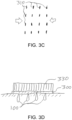
- the stretch film 300 can be applied such that the direction of compressive forces at the tissue surface (indicated by the arrows in FIG. 3B ) is in the preferred direction of shrinkage. Hole closure resulting from such compressive forces can result in a closed-hole configuration similar to the exemplary configuration shown in the top view of the treated region of FIG. 3C , where the arrows represent the direction of compressive forces, and the small vertical lines 310 represent the approximated edges of the holes 100 at the skin surface.
- Tegaderm TM Materials that can be used to form the film 300 include Tegaderm TM , another stretchable polymer, or the like.
- Tegaderm TM has adherent properties and can be stretched up to about 30-40% and then applied to the tissue surface.
- Other film materials can also be used.
- Such films can be provided with an adhesive surface, or alternatively can be adhered to the tissue surface using any appropriate biocompatible glue, cement, or adhesive.
- the compressive film 300 can be maintained on the tissue surface for several days, e.g. about 4-6 days, to facilitate sufficient healing or modification of the skin tissue while it is held in a compressed state, e.g., to minimize or prevent re-opening of the holes 100 or collagen expansion in the compressive direction by external forces.
- a stabilizing film 330 (shown in FIG. 3D ), e.g., a non-stretching film or rigid plate or the like, can be adhered to the upper surface of the film 300 after it has relaxed and compressed the tissue surface.
- This stabilizing film 330 can provide mechanical stability to the compressed tissue surface to maintain the compressive state and constrain further displacement (e.g., relaxation) of the compressed tissue during the healing process, for example, to prevent relaxation of the film 300 during the recovery process or prevent detachment of the film 300 from the skin surface.
- the stabilizing film can be adhered directly to the skin surface surrounding the treated region, e.g., beyond the edges of the stretch film 300, instead of or in addition to being adhered to the top of the stretch film 300.
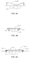
- one or more surgical staples 400 can be used to apply and maintain a compressive force on the treated region, as shown in the exemplary cross-sectional views of a treated region in FIGS. 4A and 4B .
- An exemplary large surgical staple 400 e.g., a staple large enough to span across a plurality of holes 100
- FIG. 4B shows the compressive deformation of the treated region by the inserted staple 400.
- the exemplary staple 400 can be used to provide a general compression of the treated region of skin, thereby approximating the edges of a plurality of holes 100, as shown in FIG.
- Such exemplary use of one or more surgical staples 400 may provide increased compression of the skin below the surface of the treated region as compared to that provided by application of a stretch film 300 to the skin surface (shown in FIG. 3B ), because of the anchoring and pulling together of tissue below the surface by the staple 400.
- a tensioning clip 450 as shown in FIG. 4C can be used to apply and maintain a compressive stress in the treatment region.
- the clip 450 includes two prong arrangements 460 capable of being inserted into skin.
- the prong arrangements 460 can have a sharp point or edge at their distal ends to facilitate penetration into the skin, and can be made from any material sufficiently rigid or strong to support a stress as described below without breaking or deforming significantly (e.g., a metal or rigid plastic or the like),
- the prong arrangements 460 can be connected by an elastic material 470, which can be provided as a strap, cord, or the like (e.g., similar to a rubber band, small bungee cord, or the like).
- the elastic material 4 70 can be stretched and the prong arrangements460 then inserted into skin within and/or adjacent to the treatment region that contains holes formed as described herein.
- the stretched elastic material 470 can then cause the prong arrangements 460 to exert a compressive force between them, as shown by the arrows in FIG. 4C .
- a compressive stress can be generated and maintained over at least a portion of the treatment area using a tensioning clip 450 that can be easily inserted into and removed from the skin.
- the size of the prong arrangements 460 and elastic material 470 can be selected based on the size of the treatment region and/or portion of such region over which a stress is to be maintained.
- a plurality of staples 400 and/or tensioning clips 450 can be applied within and/or across an entire treated region, or a portion thereof.
- staples 400 and/or tensioning clips 450 can be oriented in different directions on or across the treated region to vary the local preferred direction of shrinkage and/or to provide increased non-directional shrinkage of the treated region (e.g., as compared to a conventional fractional damage procedure that does not compress the treated region after holes 100 are formed).
- the staple(s) 400 and/or tensioning clips 450 can be retained in the treatment region for several days, e.g. about 4-6 days, to maintain a compressive state therein during the healing/recovery process, thereby allowing sufficient healing or modification of the skin tissue while it is held in a compressed state.
- the staples 400 and/or tensioning clips 450 can be small or thin in at least one direction, to avoid formation of visible markings upon their removal.
- staples 400 and/or tensioning clips 450 can be used that are thin and/or that include several prongs configured to pierce the skin.
- Such staples 400 and/or tensioning clips 450 can provide compressive forces comparable to a single large staple 400 or clip 450 while allowing the individual prongs to be smaller in size to reduce or eliminate formation of markings when such staples 400 and/or tensioning clips 450 are removed.
- one or more sutures 500 can be applied to the treated region apply to maintain a compressive force thereon, as shown in the exemplary cross-sectional view of FIG. 5A .
- Each suture 500 can be large enough to span across a plurality of holes 100, thereby promoting directional approximation of opposing surfaces of the holes 100, as shown in FIG. 5A .
- the suture 500 may provide increased compression of the skin below the surface of the treated region as compared to that provided by application of a stretch film 300 to the skin surface.
- a plurality of sutures 500 can be applied within and/or across an entire treated region, or a portion thereof.
- a plurality of the sutures 500 can be applied substantially parallel across the treated region, as shown in the exemplary top view of FIG. 5B .
- the arrows in FIG. 5B indicate the direction of compressive forces, and the small vertical lines 310 represent the approximated edges of the holes 100 at the skin surface.
- the sutures 500 can be applied in different directions over the treated region, such as in the exemplary configuration shown in the top view of FIG. 5C , to provide increased non-directional shrinkage of the treated region.
- the sutures 500 represent the local direction of compressive forces, which may tend to omni-directionally or isotropically compress the edges of the holes 100 at the skin surface.
- the sutures 500 can be oriented in different directions within or across the treated region to vary the local preferred direction of shrinkage within the treated region.
- the suture(s) 500 can be retained in the treatment region for several days, e.g. about 4-6 days, to maintain a compressive state therein during the healing/recovery process, thereby allowing sufficient healing or modification of the skin tissue while it is held in a compressed state.
- other devices and techniques can also be used to apply and maintain compressive forces to the perforated tissue in the treated region such as, e.g., forceps, adhesive heat-shrink films, surface application of curable liquids such as polymer precursors that can shrink and adhere to the skin surface as they cure, etc. Any such heat-shrink films, curable shrinking liquids, and the like that are known in the art may be used with certain embodiments of the present disclosure.
- any combination of stretch film 300, staples 400, sutures 500, heat-shrink films, and/or curable liquids can be used to apply and/or maintain stresses or deformations in the treated region as the holes 100 heal.
- a tensile force can be applied to a surface region of tissue to promote closure of holes 100 formed therein,
- a plurality of holes 100 can be formed in a tissue as described herein and shown in FIG. 6A .
- a tensile force can be applied to the tissue in the direction of the arrows shown in FIG. 6A .
- Such exemplary tensile force can locally stretch the tissue in the direction of the arrows, which may cause the lateral sides of the holes to approach and/or contact each other as shown in FIG. 6B .
- Such narrowing of the holes 100 can facilitate closure and healing, and result in local directional shrinkage of the tissue in a direction orthogonal to the applied tensile force as the holes heal, while tending to maintain or even slightly expand the skin in the direction of the tensile forces as the tissue damage caused by formation of the holes 100 heals.
- the tensile force can be applied using any of a variety of techniques and/or devices.
- such force can be applied manually, e.g., by pressing fingers against the skin at opposite sides of the treated region, adjacent to the perimeter thereof. The fingers can then be spread apart to apply the tensile force to the tissue, e.g., to stretch the region of tissue between the finger contact points.
- a rigid or non-stretchable adhesive film or plate can then be adhered to the stretched tissue to inhibit or prevent relaxation of the tissue as the holes heal, thereby maintaining the tissue in a stretched or tensile state.
- an expander device can be used that includes two or more contact surfaces that can be spread apart, e.g., a pair of forceps or the like having a flat contact area on the end of each tip.
- the contact areas can be pressed against the tissue and then moved apart mechanically to stretch the tissue between the contact areas.
- the contact areas can be provided with a rough, non-slip, and/or adhesive surface to maintain contact with particular locations on the skin or tissue surface as the tensile force is applied, and the expander device can be configured to maintain the expanded configuration while it is adhered to the skin surface. Other techniques to stretch the skin locally may also be used.
- the holes 100 can be exposed to saline or other solutions after they are formed, to promote hydration and softening of the tissue prior to healing.
- Such solutions can also facilitate removal of debris or impurities in the holes, e.g., removal of blood that may be present after the holes 100 are formed mechanically using one or more of the coring needles 200.
- biocompatible glues or adhesives can be used to facilitate more rapid adherence of the closed holes 100, e.g., during the healing process.
- PTB photochemical tissue bonding
- a photosensitizer e.g., rose bengal, riboflavin, porphyrins, chlorins, and the like
- a compressive film 300 or a compressive or tensile force as described herein.
- Photosensitizer precursors including, e.g., pro-drugs of such photosensitizers, can also be used, where such precursors may be metabolized or otherwise activated to form photosensitizers in the tissue.
- photoactive substances e.g., photosensitizers or precursors
- Such photoactive substances can promote tissue bonding when applied to tissue, optionally activated or allowed to metabolized, and then exposed to light having one or more appropriate wavelengths.
- the tissue can be exposed to light having an appropriate wavelength to activate the tissue bonding, to promote adhesion of the hole walls within a few minutes.
- the choice of wavelength can be based on the particular photosensitizer or precursor used.
- the material and/or object(s) imposing compressive and/or tensile forces in the treated region can then be removed while the holes 100 remain closed at the tissue surface and continue to heal.
- the stretch film 300 can be provided with a layer of one or more photosensitizers or precursors, such that at least a portion of the photoactive substance(s) is transferred onto the tissue surface when the film 300 is applied to the surface of the tissue.
- the photoactive substance(s) can be provided in a gel or micro-encapsulated layer on the surface of the film 300 that is placed against a skin surface. The activating light can then be directed through the top surface of the film 300 and onto the compressed tissue surface and the photoactive substance applied thereon.
- one or more of the various conventional photochemical tissue bonding systems, materials, and methods can be used to facilitate more rapid hole closure.
- tissue glues such as, e.g., cyanoacrylates
- tissue glues can be used to glue the holes 100 together after they are formed and compressed, stretched and/or dosed. It may be preferable to limit application of such glue to the tissue surface and avoid introduction of them within the boles 100, to avoid filling them with unwanted material that may inhibit subsequent hole closure and shrinkage.
- the use of any conventional tissue-bonding techniques or tissue glues, including those described herein, can reduce the amount of time that the compressive film 300 or other dressings are maintained over the treated tissue area as it heals, while preventing re-opening of the closed holes 100 during the gradual healing process.
- the shape, density or spacing, and pattern or spatial distribution of the holes 100, and/or the orientation of an applied compressive or tensile force to the surface of the treated region can provide a directionally-oriented shrinkage of the tissue as it heals.
- Such directionality can be utilized to achieve improved cosmetic results by generating increased shrinkage in a preferred local direction in a mechanical fractional resurfacing procedure.
- a plurality of such procedures can be applied to a particular treated region to obtain greater overall shrinkage of the skin or other tissue, preferably allowing sufficient healing time between subsequent treatments on a particular area.
- the compressive and/or tensile directions can be varied in different treatments of a single area to obtain a more homogenous shrinkage of tissue in the area.
- the sizes and preferred shrinkage directions of adjacent treated regions can also be selected and varied to achieve desirable overall shrinkage patterns for the skin or other tissue.
- a tensile or compressive force to the tissue to promote hole closure can also affect the characteristics of collagen that may be formed during the hole closure and tissue healing processes that occur after the holes 100 have been formed.
- collagen may grow and/or align in particular directions when forming in tissue that is deformed by application of external forces after the formation of the holes 100, as described herein. Such modification of collagen growth and/or alignment in the treated tissue may provide further desirable cosmetic effects.
- a system can be provided to generate a plurality of the holes 100 in a treated region of skin, and then apply a compressive or tensile force to the treated region.
- an exemplary system 700 can be provided that includes a handpiece 710 having a lower surface 715, a plurality of retractable coring needles 200, an actuator handle 720, and a compression arrangement 730, as shown in FIG. 7 .
- the needles 200 can, e.g., be affixed to a movable substrate 725 as a needle array or the like to facilitate their controllable motion and positioning relative to the lower surface 715.
- the needles 200 and the substrate 725 can be provided together as a single unit or cartridge, which can be disposable or reusable/sterilizable.
- the lower surface 715 can be configured and/or structured to be placed on the surface of a treated region, and the actuator handle 720 can be capable of positioning and/or maintaining the needles 200 and/or the substrate 725 at one or more locations relative to the lower surface 715.
- a number of the needles 200 and area of the needle array can be selected based on various factors. For example, a number of the needles 200 can be large enough to facilitate rapid treatment of large areas of skin, but not so large that the cost and complexity of the needle array becomes prohibitive. Further, it may be difficult to insert a large number of the needles 200 into the skin simultaneously. For example, such number of the needles 200 can be between, e.g., 1 and 50, or between about 6 and 25. In certain examples, a larger number of the needles 200 can be provided in the system 700. The average spacing between the needles 200 can be selected based on the inner diameter of the needles 200 and the desired fractional area of skin to be removed by a single insertion and withdrawal of the needles 200, using simple geometric calculations.
- the system 700 can (e.g., initially) be configured such that the distal ends of the needles 200 protrude a particular distance below the lower surface 715.
- Such exemplary distance can be, e.g., the approximate depth of the local dermis of the treated region.
- such distance can be adjustable (for example, using a threaded adjuster or stop, a plurality of stepped settings or the Uke, not shown) such that the system 700 can be used to treat skin having various thicknesses.
- the exemplary system 700 can be applied onto a treated region until the lower surface 715 of the system 700 contacts the skin surface, such that the needles 200 penetrate the skin tissue to the particular distance into the skin, e.g., through the entire thickness of the dermis.
- the actuator handle 720 can then be squeezed to retract the needles from the skin, pulling the distal ends of the needles 200 above the lower surface 715and forming a plurality of holes 100 in the skin.
- the actuator handle 720 can be further capable of activating the compression arrangement 730 (not shown) to apply a compression element to the treated region after the needles 200 have been withdrawn from the treated region.
- the compression arrangement 730 can include a surgical stapler configured to be mechanically or electrically actuated by the actuator handle 720, such that squeezing the actuator handle 720 will first withdraw the needles 200 from the treatment site and then apply one or more large staples 400 and/or tensioning clips 450 across at least a portion of the treated region as described herein above.
- the compression arrangement 730 can include a suture needle (e.g. a curved needle) and suture thread.
- the compression arrangement 730 can be capable of or configured for introducing one or more lengths of suture thread below the surface of the treated region, e.g., with the ends of the thread protruding from the surface of the skin, when it is actuated by the actuator handle 720, after the needles 200 are withdrawn from the treatment site.
- the ends of the suture thread can then be tied together to form a suture 500 that can apply a compressive force to the skin tissue in the treated region as described herein above.
- the compression arrangement 730 can be capable of or configured for tying off the suture thread when actuated, e.g., at a preselected tension.
- the compression arrangement 730 can include a stretch film applicator that is capable of and/or configured for adhering a stretch film 300 or the like over the treated region after the needles 200 are withdrawn from the skin.
- the compression arrangement 730 can include a small roll of stretch film 300 configured similar to a packing tape dispenser.
- the system 700 can be translated over the treated region after the needles 200 are withdrawn, to apply the film 300 over the holes 100 just formed.
- the film 300 can also be provided in pre-cut pieces that are sized to fit over the treated region.
- the compression arrangement 730 can include a reservoir of a curable coating material, as described herein above, and it can be capable of applying such coating material to the surface of the treated region after the needles 200 are withdrawn from the skin.
- the compression arrangement 730 can be configured or adapted to apply a photoactivated material (or precursor of such material), as described herein above, to at least a portion of the treated region, and directing light energy onto the region to activate the material. Examples of the system 700 in which the compression arrangement 730 is capable of applying other types of compression or tensioning elements to the treated region after the holes 100 are formed also fall within the scope of the present disclosure.
- An exemplary procedure was performed on the lower abdomen of a swine animal model to demonstrate the ability to produce directional shrinkage.
- Seven control sites of the same size were also marked between the test sites. The control sites were included to account for net growth of the animal over the course of observations.
- 144 uniformly-distributed holes were made through the depth of the skin in each test site using a specially designed vacuum-assisted 19 gauge coring needle.
- the holes were formed in a substantially random array by manually inserting and withdrawing the coring needle 144 times at arbitrary locations within the test sites.
- the width of the holes formed was approximately the same as the inside diameter of the needle, e.g., about 0.69 mm. This corresponds to a fractional surface area removal within each test site of about 6%. This corresponds to a relatively low fractional amount of skin tissue removed within the preferred ranges described herein.
- Test sites 1,2,4,5 and 6 were compressed along the langer lines that run approximately horizontally from head to tail (e.g., in the X direction).
- Test site 3 was compressed across the langer lines (in the vertical or Y direction). No stretched film was applied to the seven control sites.
- the dressing was left in place on each test site for seven days and then removed. The animal was observed, photographed and the width and height of each test and control site were measured until day 28.
- Photographic images of test site 6 taken at Day 0 (pre-treatment), Day 7 (when the dressing was removed), and Day 28, are shown in FIGS. 8A, 8B and 8C , respectively.
- the sizes of these images were adjusted such that the ruler length is the same in each.
- the overall shape of the test site changed from substantially square to rectangular from Day 0 to Day 28, with the width of the test site (in the direction of compression, along the langer lines) being about 12% smaller at the end of observation compared to the initial size of the test site.
- the height of the test site (orthogonal to the compression direction) increased by about 17% by Day 28 as compared to the pre-treatment height on Day 0. Further, no apparent scarring or markings are evident in these images, consistent with the expected cosmetic advantages of reducing skin area by formation of many very small holes.
- Table 1 below shows the measured width and height (X and Y, respectively) of each test site on Day 0, Day 7, and Day 28.
- the data suggest that the width of sites 1, 2, 4, 5 and 6 decreased slightly over the course of the observations, and that they tended to widen a bit between Day 7 (when the compressive dressing was removed) and Day 28, which may be partially attributed to relaxation of the unconstrained skin.
- the width of test site 3 increased between Day 0 and Day 7 because this site was compressed in the vertical direction, orthogonal to the other test sites.
- the height of the test sites (except for site 3), orthogonal to the compressive direction, appears to have remained about the same or increased slightly between Day 0 and Day 20.
- Table 1 Measured dimensions of each test site (in cm) at Day 0, 7, and 28 Test Site Day 0 X Day 0 Y Day 7 X Day 7 Y Day 28 X Day 28 Y 1 3.4 3.1 2.8 2.8 3.2 3.4 2 3.2 3.0 3.0 2.8 3.25 3.3 3 3.15 3.0 3.8 2.3 3.1 2.95 4 3.8 3.0 3.3 2.7 3.4 3.1 5 3.2 3.2 3.2 3.05 3.05 3.2 6 3.4 2.9 2.7 2.6 3.0 3.4
- each control site was measured at Day 0, 7 and 28.
- the measured width and height of each test site was then normalized by the average width and height, respectively, of the control sites measured on the same day. This provides a rough correction for overall growth of the animal subject (i.e., general increase in skin area) between measurements of the test site dimensions.
- Table 2 below includes the width and height of each control site as measured on Day 0, 7, and 28.
- Table 2 Measured dimensions of each control site (in cm) at Day 0, 7, and 28 Control Site Day 0 X Day 0 Y Day 7 X Day 7 Y Day 28 X Day 28 Y b 3.0 2.6 3.3 2.5 3.95 3.4 c 3.15 27 3.25 2.0 3.9 3.15 d 2.9 2.6 2.95 1.8 3.5 3.2 e 2.95 2.55 2.9 2.6 3.45 3.4 f 30 2.4 3.0 2.4 3.6 3.1 9 3.1 2.5 3.15 2.15 3.5 3.15 h 2.9 2.6 2.8 2.7 3.65 2.9 Average 3.0 2.56 3.05 2.31 3 65 3.18
- FIGS. 9A and 9B Bar graphs showing the normalized width and height (X and Y, respectively) of each test site are shown in FIGS. 9A and 9B , respectively.
- the data in these graphs suggest that there was a noticeable decrease in width of test sites 1, 2, 4, 5 and 6 over the 4 weeks following the initial treatment, when overall growth of the animal subject was accounted for.
Claims (7)
- Verwendung einer Kompressionsanordnung zum Erzeugen eines kosmetischen Effekts in Hautgewebe;
wobei die Kompressionsanordnung folgendes aufweist:(i) eine Pinzette, eine gestreckte Schicht (300) konfiguriert, um an der Haut zu haften, odereine härtbare schrumpffähige Flüssigkeit, welche konfiguriert ist, um an der Haut zu haften, wobei die Pinzette, die gestreckte Schicht und die härtbare schrumpfbare Flüssigkeit konfiguriert sind, um eine kompressive Spannung auf eine Oberfläche der Haut innerhalb eines Bereichs der zu straffenden Haut anzuwenden und aufrechtzuerhalten;oder (ii) eine Pinzette mit einer flachen Kontaktfläche an einem Ende jeder Spitze, um eine Zugspannung auf eine Oberfläche der Haut innerhalb eines Bereichs der Haut, der gestrafft werden soll, anzuwenden und aufrechtzuerhalten;oder (iii) eine starre Schicht oder eine Platte, wobei die Schicht oder Platte auf eine Oberfläche der Haut in einem Bereich der zu straffenden Haut aufgebracht wird, um eine Zugspannung aufrechtzuerhalten;und/oder (iv) ein photoaktiviertes Haftmittel, ein auf eine Oberfläche der Haut angewandtes Haftmittel, oder ein Kleber angewendet auf eine Oberfläche der Haut, um eine kompressive Spannung oder eine Zugspannung auf einer Oberfläche der Haut innerhalb eines Bereiches der Haut, welcher gestrafft werden soll, aufrechtzuerhalten:wobei eine Mehrzahl von Löchern (100), welche Breiten in einem Bereich von etwa 0,2 mm bis etwa 0,7 mm aufweisen, mit zumindestens einer Kernbohrungsnadel (200) in die Region eingeführt wurden,wobei sich die Löcher von der Oberfläche der Haut in die dermale Schicht der Haut erstrecken, wobei sich die Löcher über einen flächigen Anteil einer Oberfläche des Bereichs erstrecken, der zwischen etwa 5% und 50% liegt,wobei die Spannung eine Kraft bereitstellt in dem Bereich, entlang einer Richtung die im Wesentlichen parallel ist, zu der Oberfläche des Bereichs, undwobei die Spannung auf der Oberfläche des Bereichs aufrechterhalten wird, bis die Löcher sich im Wesentlichen geschlossen haben. - Die Verwendung gemäß Anspruch 1, wobei ein Durchmesser der Löcher zwischen etwa 0,2 mm und 0,5 mm ist.
- Die Verwendung gemäß Anspruch 1, wobei sich die Löcher über den flächigen Anteil der Oberfläche des Bereiches erstrecken, welcher zwischen etwa 10% und 30% ist oder sich durch eine ganze Tiefe der dermalen Schicht erstrecken.
- Die Verwendung gemäß Anspruch 1, wobei das photoaktivierte Haftmittel folgendes aufweist zumindest eines von Rosenbengal-Riboflavin, einem Porphyrin, einem Chlor oder einem Photosensibilisator-Precursor.
- Ein System zum Erzeugen eines kosmetischen Effekts in Hautgewebe, aufweisendzumindest eine Kernbohrungsnadel (200), welche strukturiert ist, um eine Mehrzahl von Löchern (100) in einem Bereich des Hautgewebes zu formen; undeine Kompressionsanordnung, welche aufweist:(i) eine Pinzette, ein chirurgisches Hefter, eine Nahtvorrichtung, einen Spannclip (450), eine gestreckte Schicht (300), welche konfiguriert ist, um an der Haut zu haften, oder eine härtbare schrumpffähige Flüssigkeit, welche konfiguriert ist, um an der Haut zu haften, wobei die Pinzette, der chirurgische Hefter, die Nahtvorrichtung, der Spannclip, die gestreckte Schicht und die härtbare schrumpfbare Flüssigkeit konfiguriert sind, um eine kompressive Spannung auf eine Oberfläche der Haut innerhalb eines Bereichs der zu straffenden Haut anzuwenden und aufrechtzuerhalten;oder (ii) eine Pinzette mit einer flachen Kontaktfläche an einem Ende jeder Spitze, um eine Zugspannung über zumindest einem Teil des Bereiches anzuwenden und aufrechtzuerhalten nachdem die Löcher geformt wurden;oder (iii) eine starre Schicht oder eine Platte, wobei die Schicht oder Platte auf eine Oberfläche der Haut in einem Bereich der zu straffenden Haut aufgebracht wird, um eine Zugspannung aufrechtzuerhalten;und/oder (iv) ein photoaktiviertes Haftmittel, ein auf eine Oberfläche der Haut angewandtes Haftmittel, oder ein Kleber angewendet auf eine Oberfläche der Haut, um eine kompressive Spannung oder eine Zugspannung auf einer Oberfläche der Haut innerhalb eines Bereiches der Haut, welcher gestrafft werden soll, aufrechtzuerhalten;wobei ein innerer Durchmesser der zumindest einen Kernbohrungsnadel zwischen etwa 0,2 mm und 0,7 mm ist,wobei die zumindest eine Nadel fähig zum Formen oder strukturiert ist, um die Löcher zu formen, welche sich von der Oberfläche der Haut in die dermale Schicht der Haut erstrecken, wobei sich die Löcher über einen flächigen Anteil von einer Oberfläche des Bereichs erstrecken, der zwischen etwa 5% und 50% liegt, undwobei die Kompressionsanordnung konfiguriert ist, um die Spannung aufrechtzuerhalten, welche eine Kraft in dem Bereich entlang einer Richtung bereitstellt, die im Wesentlichen parallel zur Oberfläche der Haut verläuft, bis die Löcher im Wesentlichen geschlossen sind.
- Das System gemäß Anspruch 5, wobei die zumindest eine Kernbohrungsnadel eine Mehrzahl von Kernbohrungsnadeln aufweist.
- Das System gemäß Anspruch 5, wobei der innere Durchmesser der zumindest einen Kernbohrungsnadel zwischen etwa 0,2 mm und 0,5 mm ist.
Applications Claiming Priority (2)
| Application Number | Priority Date | Filing Date | Title |
|---|---|---|---|
| US201261668744P | 2012-07-06 | 2012-07-06 | |
| PCT/US2013/049445 WO2014008470A1 (en) | 2012-07-06 | 2013-07-05 | Method and apparatus for dermatological treatment |
Publications (3)
| Publication Number | Publication Date |
|---|---|
| EP2872222A1 EP2872222A1 (de) | 2015-05-20 |
| EP2872222A4 EP2872222A4 (de) | 2016-04-20 |
| EP2872222B1 true EP2872222B1 (de) | 2023-05-31 |
Family
ID=49882510
Family Applications (1)
| Application Number | Title | Priority Date | Filing Date |
|---|---|---|---|
| EP13813955.5A Active EP2872222B1 (de) | 2012-07-06 | 2013-07-05 | System und vorrichtung zur dermatologischen behandlung |
Country Status (16)
| Country | Link |
|---|---|
| US (3) | US20150173991A1 (de) |
| EP (1) | EP2872222B1 (de) |
| JP (2) | JP2015522351A (de) |
| KR (4) | KR102560618B1 (de) |
| CN (2) | CN104902963B (de) |
| AU (2) | AU2013286576B2 (de) |
| BR (1) | BR112015000082B1 (de) |
| CA (1) | CA2878458C (de) |
| HK (1) | HK1210978A1 (de) |
| IL (1) | IL236411B (de) |
| MX (1) | MX2015000131A (de) |
| RU (1) | RU2649469C2 (de) |
| SG (1) | SG11201500075WA (de) |
| TW (2) | TWI581753B (de) |
| WO (1) | WO2014008470A1 (de) |
| ZA (2) | ZA201800043B (de) |
Families Citing this family (37)
| Publication number | Priority date | Publication date | Assignee | Title |
|---|---|---|---|---|
| US8048089B2 (en) | 2005-12-30 | 2011-11-01 | Edge Systems Corporation | Apparatus and methods for treating the skin |
| WO2009088884A1 (en) | 2008-01-04 | 2009-07-16 | Edge Systems Corporation | Apparatus and method for treating the skin |
| US8900181B2 (en) | 2009-12-18 | 2014-12-02 | Srgi Holdings, Llc | Skin treatment and drug delivery device |
| US11109887B2 (en) | 2013-12-06 | 2021-09-07 | Srgi Holdings, Llc | Pixel array medical systems, devices and methods |
| US11103275B2 (en) | 2010-12-17 | 2021-08-31 | Srgi Holdings, Llc | Pixel array medical systems, devices and methods |
| US10736653B2 (en) | 2013-12-06 | 2020-08-11 | Srgi Holdings, Llc | Pixel array medical systems, devices and methods |
| US20160317170A1 (en) | 2013-12-06 | 2016-11-03 | Edward KNOWLTON | Pixel array medical systems, devices and methods |
| US10661063B2 (en) | 2010-12-17 | 2020-05-26 | Srgi Holdings, Llc | Systems, devices and methods for fractional resection, fractional skin grafting, fractional scar reduction and fractional tattoo removal |
| US11000310B2 (en) | 2010-12-17 | 2021-05-11 | Srgi Holdings, Llc | Pixel array medical systems, devices and methods |
| US11278309B2 (en) | 2010-12-17 | 2022-03-22 | Srgi Holdings, Llc | Pixel array medical systems, devices and methods |
| US10702684B2 (en) | 2010-12-17 | 2020-07-07 | Srgi Holdings, Llc | Systems, devices and methods for fractional resection, fractional skin grafting, fractional scar reduction and fractional tattoo removal |
| US10543127B2 (en) | 2013-02-20 | 2020-01-28 | Cytrellis Biosystems, Inc. | Methods and devices for skin tightening |
| ES2936988T3 (es) | 2013-03-15 | 2023-03-23 | Hydrafacial Llc | Dispositivos y sistemas para el tratamiento de la piel |
| EP3456300A1 (de) * | 2013-05-03 | 2019-03-20 | Cytrellis Biosystems, Inc. | Mikroverbände zur hautbehandlung |
| BR112016002695B1 (pt) | 2013-08-09 | 2022-09-20 | Cytrellis Biosystems, Inc | Dispositivo com um aparelho ablativo, um aparelho de remoção e um aparelho de posicionamento |
| ES2827049T3 (es) | 2013-10-02 | 2021-05-19 | Srgi Holdings Llc | Dispositivos médicos de conjunto de píxeles |
| CA2926322C (en) | 2013-10-02 | 2022-10-18 | Srgi Holdings, Llc | Pixel array medical devices and methods |
| US11229452B2 (en) | 2013-12-06 | 2022-01-25 | Srgi Holdings, Llc | Pixel array medical systems, devices and methods |
| US11937846B2 (en) | 2013-12-06 | 2024-03-26 | Srgi Holdings Llc | Pixel array medical systems, devices and methods |
| US10953143B2 (en) | 2013-12-19 | 2021-03-23 | Cytrellis Biosystems, Inc. | Methods and devices for manipulating subdermal fat |
| EP3579767A4 (de) | 2014-10-02 | 2020-11-18 | SRGI Holdings, LLC | Medizinische systeme mit pixelanordnung, vorrichtungen und verfahren |
| CA2967636A1 (en) | 2014-11-14 | 2016-05-19 | Cytrellis Biosystems, Inc. | Devices and methods for ablation of the skin |
| EP3795204B1 (de) | 2014-12-23 | 2023-10-25 | HydraFacial LLC | Vorrichtung zur behandlung der haut mittels eines rollballens |
| US11490952B2 (en) | 2015-08-31 | 2022-11-08 | Srgi Holdings, Llc | Pixel array medical devices and methods |
| US11751903B2 (en) | 2015-08-31 | 2023-09-12 | Srgi Holdings, Llc | Pixel array medical systems, devices and methods |
| EP3981337A1 (de) * | 2015-09-27 | 2022-04-13 | Follica, Inc. | Nadelungsvorrichtung |
| US11564706B2 (en) | 2019-10-28 | 2023-01-31 | Srgi Holdings, Llc | Pixel array medical systems, devices and methods |
| JP7039478B2 (ja) * | 2016-02-25 | 2022-03-22 | ザ ジェネラル ホスピタル コーポレイション | 皮膚及び他の組織を引き締めるための方法及び装置 |
| KR20230117470A (ko) | 2016-03-29 | 2023-08-08 | 사이트렐리스 바이오시스템즈, 인크. | 미용 피부 리설페이싱용 디바이스 및 방법 |
| JP2019529043A (ja) | 2016-09-21 | 2019-10-17 | サイトレリス バイオシステムズ,インコーポレーテッド | 美容スキンリサーフェシング装置及び方法 |
| US11324673B2 (en) | 2016-11-18 | 2022-05-10 | Miraki Innovation Think Tank Llc | Cosmetic appearance of skin |
| JP7085762B2 (ja) | 2017-04-05 | 2022-06-17 | ミラキ イノベーション シンク タンク エルエルシー | 低温スラリ閉じ込め |
| AU2018250270A1 (en) | 2017-04-05 | 2019-10-31 | Miraki Innovation Think Tank Llc | Point of delivery cold slurry generation |
| WO2018217479A2 (en) * | 2017-05-11 | 2018-11-29 | Srgi Holdings, Llc | Systems, devices and methods for fractional resection, fractional skin grafting, fractional scar reduction and fractional tattoo removal |
| US10500342B2 (en) | 2017-08-21 | 2019-12-10 | Miraki Innovation Think Tank Llc | Cold slurry syringe |
| USD1016615S1 (en) | 2021-09-10 | 2024-03-05 | Hydrafacial Llc | Container for a skin treatment device |
| CN114569181B (zh) * | 2022-03-15 | 2023-10-13 | 上海交通大学医学院附属瑞金医院 | 减张胶带及其制备方法 |
Citations (4)
| Publication number | Priority date | Publication date | Assignee | Title |
|---|---|---|---|---|
| US20050283141A1 (en) * | 2004-01-23 | 2005-12-22 | Joseph Giovannoli | Method and apparatus for skin reduction |
| WO2009072711A2 (en) * | 2007-12-07 | 2009-06-11 | Myeong In Lee | Disk needle roller |
| US20120226214A1 (en) * | 2011-03-03 | 2012-09-06 | Neodyne Biosciences, Inc. | Devices and methods for skin tightening |
| WO2014008481A1 (en) * | 2012-07-06 | 2014-01-09 | The General Hospital Corporation | Method and apparatus for dermatological treatment |
Family Cites Families (34)
| Publication number | Priority date | Publication date | Assignee | Title |
|---|---|---|---|---|
| US6178346B1 (en) * | 1998-10-23 | 2001-01-23 | David C. Amundson | Infrared endoscopic imaging in a liquid with suspended particles: method and apparatus |
| DE60112293T2 (de) * | 2000-05-10 | 2006-06-01 | Canica Design Inc., Almonte | Vorrichtung zum bewegen und strecken von gewebe |
| US20080172047A1 (en) * | 2000-12-28 | 2008-07-17 | Palomar Medical Technologies, Inc. | Methods And Devices For Fractional Ablation Of Tissue |
| US7429258B2 (en) * | 2001-10-26 | 2008-09-30 | Massachusetts Institute Of Technology | Microneedle transport device |
| US20030091665A1 (en) * | 2001-11-09 | 2003-05-15 | Avon Products, Inc | Topical cosmetic composition with skin rejuvenation benefits |
| US6908453B2 (en) * | 2002-01-15 | 2005-06-21 | 3M Innovative Properties Company | Microneedle devices and methods of manufacture |
| AU2004226378A1 (en) * | 2003-03-27 | 2004-10-14 | The General Hospital Corporation | Method and apparatus for dermatological treatment and fractional skin resurfacing |
| US7500963B2 (en) * | 2003-07-22 | 2009-03-10 | Safety Syringes, Inc. | Systems and methods for automatic medical injection with safeguard |
| RU2325859C2 (ru) * | 2004-03-15 | 2008-06-10 | Марлен Андреевич Суламанидзе | Хирургическая нить и способ выполнения косметической операции |
| WO2005087283A1 (fr) * | 2004-03-15 | 2005-09-22 | Marlen Andreevich Sulamanidze | Fil chirurgical et procede pour realiser une operation chirurgicale |
| ATE372813T1 (de) * | 2004-07-09 | 2007-09-15 | Johnson & Johnson Gmbh | Kosmetische zusammensetzung zur entfernung von schminke sowie ein artikel enthaltend genannte zusammensetzung |
| US7850683B2 (en) * | 2005-05-20 | 2010-12-14 | Myoscience, Inc. | Subdermal cryogenic remodeling of muscles, nerves, connective tissue, and/or adipose tissue (fat) |
| US20070038181A1 (en) * | 2005-08-09 | 2007-02-15 | Alexander Melamud | Method, system and device for delivering a substance to tissue |
| US9486274B2 (en) * | 2005-09-07 | 2016-11-08 | Ulthera, Inc. | Dissection handpiece and method for reducing the appearance of cellulite |
| ATE498027T1 (de) * | 2005-12-07 | 2011-02-15 | Univ Ramot | Wirkstoffabgebende verbundkörper |
| US20070239236A1 (en) * | 2006-04-07 | 2007-10-11 | The General Hospital Corporation | Method and apparatus for producing thermal damage within the skin |
| RU61559U1 (ru) * | 2006-06-06 | 2007-03-10 | Марият Мурадалиевна Мухина | Игла для иглорефлексотерапии (варианты) |
| WO2008019051A2 (en) * | 2006-08-03 | 2008-02-14 | The Board Of Trustees Of The Leland Stanford Junior University | Devices and bandages for the treatment or prevention of scars and/or keloids and methods and kits therefor |
| WO2008052189A2 (en) * | 2006-10-26 | 2008-05-02 | Reliant Technologies, Inc. | Micropore delivery of active substances |
| TW200841866A (en) * | 2007-04-25 | 2008-11-01 | Micro Base Technology Corp | Cosmetic or medical patch structure |
| GB0719037D0 (en) * | 2007-09-28 | 2007-11-07 | Vitrolife Sweden Ab | Sampling needle |
| CA2739097C (en) * | 2008-04-01 | 2019-01-15 | The General Hospital Corporation | Method and apparatus for tissue grafting |
| WO2010017477A2 (en) * | 2008-08-07 | 2010-02-11 | The General Hospital Corporation | Method and apparatus for dermatological hypopigmentation |
| IT1394690B1 (it) * | 2008-10-23 | 2012-07-13 | Carli De | Metodo di trattamento dermocosmetico della cute mediante applicazione di composizioni contenenti ngf. |
| KR20130062925A (ko) * | 2010-03-29 | 2013-06-13 | 폴리카 인코포레이티드 | 조합 요법 |
| KR101815035B1 (ko) * | 2010-05-07 | 2018-01-08 | 더 제너럴 하스피탈 코포레이션 | 조직이식과 조직복제 장치 |
| WO2011163264A2 (en) * | 2010-06-21 | 2011-12-29 | Candela Corporation | Driving microneedle arrays into skin and delivering rf energy |
| EP2667805B1 (de) * | 2011-01-28 | 2023-04-05 | The General Hospital Corporation | Gewebebiopsievorrichtung und -verfahren |
| CA2825950C (en) * | 2011-01-28 | 2019-06-18 | The General Hospital Corporation | Method and apparatus for skin resurfacing |
| US8523849B2 (en) * | 2011-02-03 | 2013-09-03 | Tria Beauty, Inc. | Radiation-based dermatological devices and methods |
| CN102178616B (zh) * | 2011-05-06 | 2013-06-05 | 广州保税区雅兰国际化妆品有限公司 | 一种玻尿酸微针贴膜及其制备方法 |
| CN202113484U (zh) * | 2011-05-23 | 2012-01-18 | 苏州东邦医疗器械有限公司 | 皮肤施术用模块 |
| US20130110026A1 (en) * | 2011-07-27 | 2013-05-02 | Neodyne Biosciences, Inc. | Strained skin treatment devices and methods |
| EP3456300A1 (de) * | 2013-05-03 | 2019-03-20 | Cytrellis Biosystems, Inc. | Mikroverbände zur hautbehandlung |
-
2013
- 2013-07-05 CN CN201380036142.7A patent/CN104902963B/zh active Active
- 2013-07-05 KR KR1020227006648A patent/KR102560618B1/ko active IP Right Grant
- 2013-07-05 AU AU2013286576A patent/AU2013286576B2/en active Active
- 2013-07-05 CN CN201810128503.5A patent/CN108209994B/zh active Active
- 2013-07-05 KR KR1020237025126A patent/KR102658717B1/ko active IP Right Grant
- 2013-07-05 TW TW102124230A patent/TWI581753B/zh active
- 2013-07-05 JP JP2015520708A patent/JP2015522351A/ja active Pending
- 2013-07-05 US US14/412,079 patent/US20150173991A1/en not_active Abandoned
- 2013-07-05 SG SG11201500075WA patent/SG11201500075WA/en unknown
- 2013-07-05 WO PCT/US2013/049445 patent/WO2014008470A1/en active Application Filing
- 2013-07-05 KR KR1020157003050A patent/KR102370581B1/ko active IP Right Grant
- 2013-07-05 RU RU2015103835A patent/RU2649469C2/ru active
- 2013-07-05 EP EP13813955.5A patent/EP2872222B1/de active Active
- 2013-07-05 BR BR112015000082-7A patent/BR112015000082B1/pt active IP Right Grant
- 2013-07-05 CA CA2878458A patent/CA2878458C/en active Active
- 2013-07-05 KR KR1020247011272A patent/KR20240050464A/ko active Application Filing
- 2013-07-05 TW TW106106160A patent/TWI629044B/zh active
- 2013-07-05 MX MX2015000131A patent/MX2015000131A/es unknown
-
2014
- 2014-12-23 IL IL23641114A patent/IL236411B/en active IP Right Grant
-
2015
- 2015-11-19 HK HK15111415.7A patent/HK1210978A1/xx unknown
-
2017
- 2017-08-16 US US15/678,959 patent/US20180008500A1/en not_active Abandoned
-
2018
- 2018-01-04 ZA ZA2018/00043A patent/ZA201800043B/en unknown
- 2018-05-10 AU AU2018203245A patent/AU2018203245B2/en active Active
- 2018-06-27 JP JP2018121710A patent/JP7072451B2/ja active Active
-
2019
- 2019-01-03 ZA ZA2019/00021A patent/ZA201900021B/en unknown
-
2021
- 2021-04-09 US US17/226,889 patent/US11813218B2/en active Active
Patent Citations (4)
| Publication number | Priority date | Publication date | Assignee | Title |
|---|---|---|---|---|
| US20050283141A1 (en) * | 2004-01-23 | 2005-12-22 | Joseph Giovannoli | Method and apparatus for skin reduction |
| WO2009072711A2 (en) * | 2007-12-07 | 2009-06-11 | Myeong In Lee | Disk needle roller |
| US20120226214A1 (en) * | 2011-03-03 | 2012-09-06 | Neodyne Biosciences, Inc. | Devices and methods for skin tightening |
| WO2014008481A1 (en) * | 2012-07-06 | 2014-01-09 | The General Hospital Corporation | Method and apparatus for dermatological treatment |
Non-Patent Citations (1)
| Title |
|---|
| EMMANUEL THANOS ET AL: "Suturing Skills for Medical Students: A Systematic Review", IN VIVO: INTERNATIONAL JOURNAL OF EXPERIMENTAL AND CLINICAL PATHOPHYSIOLOGY AND DRUG RESEARCH, vol. 35, no. 1, 1 January 2021 (2021-01-01), GR, pages 1 - 12, XP055903388, ISSN: 0258-851X, Retrieved from the Internet <URL:https://www.ncbi.nlm.nih.gov/pmc/articles/PMC7880767/pdf/in_vivo-35-1.pdf> [retrieved on 20220321], DOI: 10.21873/invivo.12226 * |
Also Published As
Similar Documents
| Publication | Publication Date | Title |
|---|---|---|
| US11813218B2 (en) | Method and apparatus for dermatological treatment | |
| EP2872216B1 (de) | System und vorrichtung zur dermatologischen behandlung | |
| US11701262B2 (en) | Devices and methods for skin tightening | |
| CA2554504C (en) | Method and apparatus for excising skin | |
| US20070068537A1 (en) | Method and apparatus for skin reduction | |
| US20140031801A1 (en) | Method and apparatus for skin reduction | |
| MXPA02010751A (es) | Sistema y metodo para mover y estirar tejido plastico. | |
| US20140081251A1 (en) | Method and aparatus for skin reduction | |
| US10888375B2 (en) | Method and apparatus for dermatological treatment |
Legal Events
| Date | Code | Title | Description |
|---|---|---|---|
| PUAI | Public reference made under article 153(3) epc to a published international application that has entered the european phase |
Free format text: ORIGINAL CODE: 0009012 |
|
| 17P | Request for examination filed |
Effective date: 20150408 |
|
| AK | Designated contracting states |
Kind code of ref document: A1 Designated state(s): AL AT BE BG CH CY CZ DE DK EE ES FI FR GB GR HR HU IE IS IT LI LT LU LV MC MK MT NL NO PL PT RO RS SE SI SK SM TR |
|
| AX | Request for extension of the european patent |
Extension state: BA ME |
|
| DAX | Request for extension of the european patent (deleted) | ||
| RA4 | Supplementary search report drawn up and despatched (corrected) |
Effective date: 20160318 |
|
| RIC1 | Information provided on ipc code assigned before grant |
Ipc: A61Q 19/08 20060101AFI20160314BHEP Ipc: A61B 17/00 20060101ALI20160314BHEP |
|
| REG | Reference to a national code |
Ref country code: HK Ref legal event code: DE Ref document number: 1210978 Country of ref document: HK |
|
| STAA | Information on the status of an ep patent application or granted ep patent |
Free format text: STATUS: EXAMINATION IS IN PROGRESS |
|
| 17Q | First examination report despatched |
Effective date: 20200107 |
|
| STAA | Information on the status of an ep patent application or granted ep patent |
Free format text: STATUS: EXAMINATION IS IN PROGRESS |
|
| REG | Reference to a national code |
Ref country code: DE Ref legal event code: R079 Ref document number: 602013083871 Country of ref document: DE Free format text: PREVIOUS MAIN CLASS: A61Q0019080000 Ipc: A61B0017040000 |
|
| GRAP | Despatch of communication of intention to grant a patent |
Free format text: ORIGINAL CODE: EPIDOSNIGR1 |
|
| STAA | Information on the status of an ep patent application or granted ep patent |
Free format text: STATUS: GRANT OF PATENT IS INTENDED |
|
| RIC1 | Information provided on ipc code assigned before grant |
Ipc: A61B 17/20 20060101ALN20221123BHEP Ipc: A61K 8/02 20060101ALI20221123BHEP Ipc: A61Q 19/08 20060101ALI20221123BHEP Ipc: A61B 17/064 20060101ALI20221123BHEP Ipc: A61B 17/04 20060101AFI20221123BHEP |
|
| INTG | Intention to grant announced |
Effective date: 20221208 |
|
| GRAS | Grant fee paid |
Free format text: ORIGINAL CODE: EPIDOSNIGR3 |
|
| GRAA | (expected) grant |
Free format text: ORIGINAL CODE: 0009210 |
|
| STAA | Information on the status of an ep patent application or granted ep patent |
Free format text: STATUS: THE PATENT HAS BEEN GRANTED |
|
| AK | Designated contracting states |
Kind code of ref document: B1 Designated state(s): AL AT BE BG CH CY CZ DE DK EE ES FI FR GB GR HR HU IE IS IT LI LT LU LV MC MK MT NL NO PL PT RO RS SE SI SK SM TR |
|
| REG | Reference to a national code |
Ref country code: GB Ref legal event code: FG4D Ref country code: CH Ref legal event code: EP |
|
| P01 | Opt-out of the competence of the unified patent court (upc) registered |
Effective date: 20230509 |
|
| REG | Reference to a national code |
Ref country code: AT Ref legal event code: REF Ref document number: 1570504 Country of ref document: AT Kind code of ref document: T Effective date: 20230615 Ref country code: DE Ref legal event code: R096 Ref document number: 602013083871 Country of ref document: DE |
|
| REG | Reference to a national code |
Ref country code: IE Ref legal event code: FG4D |
|
| REG | Reference to a national code |
Ref country code: LT Ref legal event code: MG9D |
|
| REG | Reference to a national code |
Ref country code: NL Ref legal event code: MP Effective date: 20230531 |
|
| REG | Reference to a national code |
Ref country code: AT Ref legal event code: MK05 Ref document number: 1570504 Country of ref document: AT Kind code of ref document: T Effective date: 20230531 |
|
| PG25 | Lapsed in a contracting state [announced via postgrant information from national office to epo] |
Ref country code: SE Free format text: LAPSE BECAUSE OF FAILURE TO SUBMIT A TRANSLATION OF THE DESCRIPTION OR TO PAY THE FEE WITHIN THE PRESCRIBED TIME-LIMIT Effective date: 20230531 Ref country code: NO Free format text: LAPSE BECAUSE OF FAILURE TO SUBMIT A TRANSLATION OF THE DESCRIPTION OR TO PAY THE FEE WITHIN THE PRESCRIBED TIME-LIMIT Effective date: 20230831 Ref country code: ES Free format text: LAPSE BECAUSE OF FAILURE TO SUBMIT A TRANSLATION OF THE DESCRIPTION OR TO PAY THE FEE WITHIN THE PRESCRIBED TIME-LIMIT Effective date: 20230531 Ref country code: AT Free format text: LAPSE BECAUSE OF FAILURE TO SUBMIT A TRANSLATION OF THE DESCRIPTION OR TO PAY THE FEE WITHIN THE PRESCRIBED TIME-LIMIT Effective date: 20230531 |
|
| PGFP | Annual fee paid to national office [announced via postgrant information from national office to epo] |
Ref country code: GB Payment date: 20230727 Year of fee payment: 11 |
|
| PG25 | Lapsed in a contracting state [announced via postgrant information from national office to epo] |
Ref country code: RS Free format text: LAPSE BECAUSE OF FAILURE TO SUBMIT A TRANSLATION OF THE DESCRIPTION OR TO PAY THE FEE WITHIN THE PRESCRIBED TIME-LIMIT Effective date: 20230531 Ref country code: PL Free format text: LAPSE BECAUSE OF FAILURE TO SUBMIT A TRANSLATION OF THE DESCRIPTION OR TO PAY THE FEE WITHIN THE PRESCRIBED TIME-LIMIT Effective date: 20230531 Ref country code: NL Free format text: LAPSE BECAUSE OF FAILURE TO SUBMIT A TRANSLATION OF THE DESCRIPTION OR TO PAY THE FEE WITHIN THE PRESCRIBED TIME-LIMIT Effective date: 20230531 Ref country code: LV Free format text: LAPSE BECAUSE OF FAILURE TO SUBMIT A TRANSLATION OF THE DESCRIPTION OR TO PAY THE FEE WITHIN THE PRESCRIBED TIME-LIMIT Effective date: 20230531 Ref country code: LT Free format text: LAPSE BECAUSE OF FAILURE TO SUBMIT A TRANSLATION OF THE DESCRIPTION OR TO PAY THE FEE WITHIN THE PRESCRIBED TIME-LIMIT Effective date: 20230531 Ref country code: IS Free format text: LAPSE BECAUSE OF FAILURE TO SUBMIT A TRANSLATION OF THE DESCRIPTION OR TO PAY THE FEE WITHIN THE PRESCRIBED TIME-LIMIT Effective date: 20230930 Ref country code: HR Free format text: LAPSE BECAUSE OF FAILURE TO SUBMIT A TRANSLATION OF THE DESCRIPTION OR TO PAY THE FEE WITHIN THE PRESCRIBED TIME-LIMIT Effective date: 20230531 Ref country code: GR Free format text: LAPSE BECAUSE OF FAILURE TO SUBMIT A TRANSLATION OF THE DESCRIPTION OR TO PAY THE FEE WITHIN THE PRESCRIBED TIME-LIMIT Effective date: 20230901 |
|
| PGFP | Annual fee paid to national office [announced via postgrant information from national office to epo] |
Ref country code: FR Payment date: 20230725 Year of fee payment: 11 Ref country code: DE Payment date: 20230727 Year of fee payment: 11 |
|
| PG25 | Lapsed in a contracting state [announced via postgrant information from national office to epo] |
Ref country code: FI Free format text: LAPSE BECAUSE OF FAILURE TO SUBMIT A TRANSLATION OF THE DESCRIPTION OR TO PAY THE FEE WITHIN THE PRESCRIBED TIME-LIMIT Effective date: 20230531 |
|
| PG25 | Lapsed in a contracting state [announced via postgrant information from national office to epo] |
Ref country code: SK Free format text: LAPSE BECAUSE OF FAILURE TO SUBMIT A TRANSLATION OF THE DESCRIPTION OR TO PAY THE FEE WITHIN THE PRESCRIBED TIME-LIMIT Effective date: 20230531 |
|
| PG25 | Lapsed in a contracting state [announced via postgrant information from national office to epo] |
Ref country code: SM Free format text: LAPSE BECAUSE OF FAILURE TO SUBMIT A TRANSLATION OF THE DESCRIPTION OR TO PAY THE FEE WITHIN THE PRESCRIBED TIME-LIMIT Effective date: 20230531 Ref country code: SK Free format text: LAPSE BECAUSE OF FAILURE TO SUBMIT A TRANSLATION OF THE DESCRIPTION OR TO PAY THE FEE WITHIN THE PRESCRIBED TIME-LIMIT Effective date: 20230531 Ref country code: RO Free format text: LAPSE BECAUSE OF FAILURE TO SUBMIT A TRANSLATION OF THE DESCRIPTION OR TO PAY THE FEE WITHIN THE PRESCRIBED TIME-LIMIT Effective date: 20230531 Ref country code: PT Free format text: LAPSE BECAUSE OF FAILURE TO SUBMIT A TRANSLATION OF THE DESCRIPTION OR TO PAY THE FEE WITHIN THE PRESCRIBED TIME-LIMIT Effective date: 20231002 Ref country code: EE Free format text: LAPSE BECAUSE OF FAILURE TO SUBMIT A TRANSLATION OF THE DESCRIPTION OR TO PAY THE FEE WITHIN THE PRESCRIBED TIME-LIMIT Effective date: 20230531 Ref country code: DK Free format text: LAPSE BECAUSE OF FAILURE TO SUBMIT A TRANSLATION OF THE DESCRIPTION OR TO PAY THE FEE WITHIN THE PRESCRIBED TIME-LIMIT Effective date: 20230531 Ref country code: CZ Free format text: LAPSE BECAUSE OF FAILURE TO SUBMIT A TRANSLATION OF THE DESCRIPTION OR TO PAY THE FEE WITHIN THE PRESCRIBED TIME-LIMIT Effective date: 20230531 |
|
| PG25 | Lapsed in a contracting state [announced via postgrant information from national office to epo] |
Ref country code: MC Free format text: LAPSE BECAUSE OF FAILURE TO SUBMIT A TRANSLATION OF THE DESCRIPTION OR TO PAY THE FEE WITHIN THE PRESCRIBED TIME-LIMIT Effective date: 20230531 |
|
| PG25 | Lapsed in a contracting state [announced via postgrant information from national office to epo] |
Ref country code: MC Free format text: LAPSE BECAUSE OF FAILURE TO SUBMIT A TRANSLATION OF THE DESCRIPTION OR TO PAY THE FEE WITHIN THE PRESCRIBED TIME-LIMIT Effective date: 20230531 |
|
| REG | Reference to a national code |
Ref country code: CH Ref legal event code: PL |
|
| REG | Reference to a national code |
Ref country code: DE Ref legal event code: R097 Ref document number: 602013083871 Country of ref document: DE |
|
| REG | Reference to a national code |
Ref country code: BE Ref legal event code: MM Effective date: 20230731 |
|
| PG25 | Lapsed in a contracting state [announced via postgrant information from national office to epo] |
Ref country code: LU Free format text: LAPSE BECAUSE OF NON-PAYMENT OF DUE FEES Effective date: 20230705 |
|
| PG25 | Lapsed in a contracting state [announced via postgrant information from national office to epo] |
Ref country code: LU Free format text: LAPSE BECAUSE OF NON-PAYMENT OF DUE FEES Effective date: 20230705 |
|
| PLBE | No opposition filed within time limit |
Free format text: ORIGINAL CODE: 0009261 |
|
| STAA | Information on the status of an ep patent application or granted ep patent |
Free format text: STATUS: NO OPPOSITION FILED WITHIN TIME LIMIT |
|
| PG25 | Lapsed in a contracting state [announced via postgrant information from national office to epo] |
Ref country code: CH Free format text: LAPSE BECAUSE OF NON-PAYMENT OF DUE FEES Effective date: 20230731 |
|
| PG25 | Lapsed in a contracting state [announced via postgrant information from national office to epo] |
Ref country code: SI Free format text: LAPSE BECAUSE OF FAILURE TO SUBMIT A TRANSLATION OF THE DESCRIPTION OR TO PAY THE FEE WITHIN THE PRESCRIBED TIME-LIMIT Effective date: 20230531 |
|
| 26N | No opposition filed |
Effective date: 20240301 |