EP2871366B1 - Rotary compressor - Google Patents
Rotary compressor Download PDFInfo
- Publication number
- EP2871366B1 EP2871366B1 EP13817101.2A EP13817101A EP2871366B1 EP 2871366 B1 EP2871366 B1 EP 2871366B1 EP 13817101 A EP13817101 A EP 13817101A EP 2871366 B1 EP2871366 B1 EP 2871366B1
- Authority
- EP
- European Patent Office
- Prior art keywords
- oil reservoir
- oil
- rotary compressor
- cylinder
- suppressing portion
- Prior art date
- Legal status (The legal status is an assumption and is not a legal conclusion. Google has not performed a legal analysis and makes no representation as to the accuracy of the status listed.)
- Not-in-force
Links
Images


Classifications
-
- F—MECHANICAL ENGINEERING; LIGHTING; HEATING; WEAPONS; BLASTING
- F04—POSITIVE - DISPLACEMENT MACHINES FOR LIQUIDS; PUMPS FOR LIQUIDS OR ELASTIC FLUIDS
- F04C—ROTARY-PISTON, OR OSCILLATING-PISTON, POSITIVE-DISPLACEMENT MACHINES FOR LIQUIDS; ROTARY-PISTON, OR OSCILLATING-PISTON, POSITIVE-DISPLACEMENT PUMPS
- F04C29/00—Component parts, details or accessories of pumps or pumping installations, not provided for in groups F04C18/00 - F04C28/00
- F04C29/02—Lubrication; Lubricant separation
- F04C29/028—Means for improving or restricting lubricant flow
-
- F—MECHANICAL ENGINEERING; LIGHTING; HEATING; WEAPONS; BLASTING
- F04—POSITIVE - DISPLACEMENT MACHINES FOR LIQUIDS; PUMPS FOR LIQUIDS OR ELASTIC FLUIDS
- F04C—ROTARY-PISTON, OR OSCILLATING-PISTON, POSITIVE-DISPLACEMENT MACHINES FOR LIQUIDS; ROTARY-PISTON, OR OSCILLATING-PISTON, POSITIVE-DISPLACEMENT PUMPS
- F04C18/00—Rotary-piston pumps specially adapted for elastic fluids
- F04C18/30—Rotary-piston pumps specially adapted for elastic fluids having the characteristics covered by two or more of groups F04C18/02, F04C18/08, F04C18/22, F04C18/24, F04C18/48, or having the characteristics covered by one of these groups together with some other type of movement between co-operating members
- F04C18/34—Rotary-piston pumps specially adapted for elastic fluids having the characteristics covered by two or more of groups F04C18/02, F04C18/08, F04C18/22, F04C18/24, F04C18/48, or having the characteristics covered by one of these groups together with some other type of movement between co-operating members having the movement defined in group F04C18/08 or F04C18/22 and relative reciprocation between the co-operating members
- F04C18/356—Rotary-piston pumps specially adapted for elastic fluids having the characteristics covered by two or more of groups F04C18/02, F04C18/08, F04C18/22, F04C18/24, F04C18/48, or having the characteristics covered by one of these groups together with some other type of movement between co-operating members having the movement defined in group F04C18/08 or F04C18/22 and relative reciprocation between the co-operating members with vanes reciprocating with respect to the outer member
- F04C18/3562—Rotary-piston pumps specially adapted for elastic fluids having the characteristics covered by two or more of groups F04C18/02, F04C18/08, F04C18/22, F04C18/24, F04C18/48, or having the characteristics covered by one of these groups together with some other type of movement between co-operating members having the movement defined in group F04C18/08 or F04C18/22 and relative reciprocation between the co-operating members with vanes reciprocating with respect to the outer member the inner and outer member being in contact along one line or continuous surfaces substantially parallel to the axis of rotation
- F04C18/3564—Rotary-piston pumps specially adapted for elastic fluids having the characteristics covered by two or more of groups F04C18/02, F04C18/08, F04C18/22, F04C18/24, F04C18/48, or having the characteristics covered by one of these groups together with some other type of movement between co-operating members having the movement defined in group F04C18/08 or F04C18/22 and relative reciprocation between the co-operating members with vanes reciprocating with respect to the outer member the inner and outer member being in contact along one line or continuous surfaces substantially parallel to the axis of rotation the surfaces of the inner and outer member, forming the working space, being surfaces of revolution
-
- F—MECHANICAL ENGINEERING; LIGHTING; HEATING; WEAPONS; BLASTING
- F04—POSITIVE - DISPLACEMENT MACHINES FOR LIQUIDS; PUMPS FOR LIQUIDS OR ELASTIC FLUIDS
- F04C—ROTARY-PISTON, OR OSCILLATING-PISTON, POSITIVE-DISPLACEMENT MACHINES FOR LIQUIDS; ROTARY-PISTON, OR OSCILLATING-PISTON, POSITIVE-DISPLACEMENT PUMPS
- F04C23/00—Combinations of two or more pumps, each being of rotary-piston or oscillating-piston type, specially adapted for elastic fluids; Pumping installations specially adapted for elastic fluids; Multi-stage pumps specially adapted for elastic fluids
- F04C23/008—Hermetic pumps
-
- F—MECHANICAL ENGINEERING; LIGHTING; HEATING; WEAPONS; BLASTING
- F04—POSITIVE - DISPLACEMENT MACHINES FOR LIQUIDS; PUMPS FOR LIQUIDS OR ELASTIC FLUIDS
- F04C—ROTARY-PISTON, OR OSCILLATING-PISTON, POSITIVE-DISPLACEMENT MACHINES FOR LIQUIDS; ROTARY-PISTON, OR OSCILLATING-PISTON, POSITIVE-DISPLACEMENT PUMPS
- F04C29/00—Component parts, details or accessories of pumps or pumping installations, not provided for in groups F04C18/00 - F04C28/00
- F04C29/04—Heating; Cooling; Heat insulation
-
- F—MECHANICAL ENGINEERING; LIGHTING; HEATING; WEAPONS; BLASTING
- F04—POSITIVE - DISPLACEMENT MACHINES FOR LIQUIDS; PUMPS FOR LIQUIDS OR ELASTIC FLUIDS
- F04C—ROTARY-PISTON, OR OSCILLATING-PISTON, POSITIVE-DISPLACEMENT MACHINES FOR LIQUIDS; ROTARY-PISTON, OR OSCILLATING-PISTON, POSITIVE-DISPLACEMENT PUMPS
- F04C2240/00—Components
- F04C2240/30—Casings or housings
-
- F—MECHANICAL ENGINEERING; LIGHTING; HEATING; WEAPONS; BLASTING
- F04—POSITIVE - DISPLACEMENT MACHINES FOR LIQUIDS; PUMPS FOR LIQUIDS OR ELASTIC FLUIDS
- F04C—ROTARY-PISTON, OR OSCILLATING-PISTON, POSITIVE-DISPLACEMENT MACHINES FOR LIQUIDS; ROTARY-PISTON, OR OSCILLATING-PISTON, POSITIVE-DISPLACEMENT PUMPS
- F04C2240/00—Components
- F04C2240/80—Other components
- F04C2240/809—Lubricant sump
-
- F—MECHANICAL ENGINEERING; LIGHTING; HEATING; WEAPONS; BLASTING
- F04—POSITIVE - DISPLACEMENT MACHINES FOR LIQUIDS; PUMPS FOR LIQUIDS OR ELASTIC FLUIDS
- F04C—ROTARY-PISTON, OR OSCILLATING-PISTON, POSITIVE-DISPLACEMENT MACHINES FOR LIQUIDS; ROTARY-PISTON, OR OSCILLATING-PISTON, POSITIVE-DISPLACEMENT PUMPS
- F04C23/00—Combinations of two or more pumps, each being of rotary-piston or oscillating-piston type, specially adapted for elastic fluids; Pumping installations specially adapted for elastic fluids; Multi-stage pumps specially adapted for elastic fluids
- F04C23/001—Combinations of two or more pumps, each being of rotary-piston or oscillating-piston type, specially adapted for elastic fluids; Pumping installations specially adapted for elastic fluids; Multi-stage pumps specially adapted for elastic fluids of similar working principle
Definitions
- the present invention relates to rotary compressors.
- Rotary compressors are widely used in electrical appliances such as air conditioners, heaters, and hot water dispensers.
- a technique for suppressing a so-called heat loss i.e., a decrease in efficiency caused by the fact that a refrigerant drawn into a compression chamber (a drawn refrigerant) receives heat from the environment.
- a rotary compressor of Patent Literature 1 has a closed space provided in the suction-side portion of a cylinder as means for suppressing heat reception by a drawn refrigerant.
- the closed space suppresses heat transfer from the high-temperature refrigerant in the closed casing to the inner wall of the cylinder.
- a rotary compressor including:
- the communication path is located on the same side as the discharge port with respect to a reference plane, the reference plane being a plane including a central axis of the cylinder and passing through a contact line that is formed between an inner circumferential surface of the cylinder and an outer circumferential surface of the piston when the vane protrudes maximally toward the central axis of the cylinder.
- the oil reservoir is divided by the convection suppressing portion into a plurality of sections in the vertical direction.
- the communication path allows the plurality of sections of the oil reservoir to communicate with each other.
- the communication path is located on the same side as the discharge port with respect to the reference plane. Therefore, the oil in the oil reservoir can be stagnated on the same side as the suction port with respect to the reference plane. Accordingly, the heat transfer coefficient on the wall surface of the compression mechanism is decreased on the same side as the suction port with respect to the reference plane, which can suppress transfer of heat from the oil to the drawn refrigerant through the wall surface of the compression mechanism. Consequently, the volumetric efficiency of the rotary compressor is enhanced.
- a first aspect of the present disclosure provides a rotary compressor including:
- the communication path is located on the same side as the discharge port with respect to a reference plane, the reference plane being a plane including a central axis of the cylinder and passing through a contact line that is formed between an inner circumferential surface of the cylinder and an outer circumferential surface of the piston when the vane protrudes maximally toward the central axis of the cylinder.
- a second aspect provides the rotary compressor as set forth in the first aspect, wherein the communication path is a communication hole formed in the convection suppressing portion. Formation of the communication hole in the convection suppressing portion is easy, and is desirable from a design standpoint.
- a third aspect provides the rotary compressor as set forth in the second aspect, wherein the convection suppressing portion has two holes as the communication hole.
- a fourth aspect provides the rotary compressor as set forth in any one of the first to third aspects, wherein the convection suppressing portion includes a plate-shaped member.
- a fifth aspect provides the rotary compressor as set forth in any one of the first to fourth aspects, wherein the convection suppressing portion is formed integrally with a component of the compression mechanism.
- a sixth aspect provides the rotary compressor as set forth in any one of the first to fifth aspects, further including: a second convection suppressing portion disposed closer to a surface of the oil than the convection suppressing portion and dividing a selected one of the plurality of sections of the oil reservoir further into a plurality of sections in the vertical direction; and a second communication path that allows the plurality of sections separated by the second convection suppressing portion to communicate with each other, wherein the second communication path is located on the same side as the discharge port with respect to the reference plane.
- a rotary compressor 100A of the present embodiment is a hermetic compressor, and includes a closed casing 1, a motor 7, a compression mechanism 48, and a shaft 10.
- the compression mechanism 48 has an upper muffler 33, an upper sealing member 18 (upper bearing member), a first compression block 28, an intermediate plate 19, a second compression block 38, a lower sealing member 24 (lower bearing member), and a lower end-face plate 34.
- the compression blocks 28 and 38 are sandwiched between the upper sealing member 18 (upper bearing member) and the lower sealing member 24 (lower bearing member).
- the intermediate plate 19 is disposed between the first compression block 28 and the second compression block 38.
- the motor 7 is disposed above the upper sealing member 18 in the closed casing 1.
- the shaft 10 extends in a vertical direction.
- the compression mechanism 48 is coupled to the motor 7 by the shaft 10.
- a terminal 11 for supplying electric power to the motor 7 is provided on the top of the closed casing 1.
- the closed casing 1 has an internal space 13 to be filled with a refrigerant (working fluid) compressed by the compression mechanism 48.
- An oil reservoir 12 is formed at the bottom of the closed casing 1.
- a suction pipe 3, a suction pipe 4, and a discharge pipe 5 are connected to the closed casing 1.
- the suction pipe 3 penetrates through a trunk portion of the closed casing 1, and connects an accumulator (omitted from the drawings) to the first compression block 28.
- the suction pipe 4 penetrates through the trunk portion of the closed casing 1, and connects the accumulator to the second compression block 38.
- the suction pipes 3 and 4 serve to introduce the refrigerant to be compressed from the accumulator to the compression blocks 28 and 38.
- the discharge pipe 5 penetrates through the top of the closed casing 1, and opens into the internal space 13 of the closed casing 1.
- the discharge pipe 5 serves to discharge the compressed refrigerant to the outside of the rotary compressor 100A.
- the motor 7 is composed of a stator 7a and a rotor 7b.
- the stator 7a is secured to the inner circumferential surface of the closed casing 1.
- the rotor 7b is secured to the shaft 10, and rotates together with the shaft 10.
- An oil feed path 10d is formed in a central portion of the shaft 10.
- An oil feed mechanism 10c oil pump that pumps up an oil of the oil reservoir 12 and feeds the oil to the oil feed path 10d is provided in a lower end portion of the shaft 10.
- the compression mechanism 48 is disposed inside the closed casing 1 in such a manner as to be immersed in the oil held in the oil reservoir 12.
- the first compression block 28 and the second compression block 38 are arranged in a direction parallel to the rotation axis of the shaft 10.
- the first compression block 28 has a suction port 8a and a discharge port 8b, and is driven by the motor 7 to draw the refrigerant through the suction port 8a, compress the refrigerant, and then discharge the refrigerant thorough the discharge port 8b.
- the second compression block 38 has a suction port 8c and a discharge port 8d, and is driven by the motor 7 to draw the refrigerant through the suction port 8c, compress the refrigerant, and then discharge the refrigerant through the discharge port 8d.
- the internal space 13 of the closed casing 1 is filled with the refrigerant discharged from the compression blocks 28 and 38.
- the structure of the first compression block 28 is the same as the structure of the second compression block 38.
- the compression blocks 28 and 38 are each composed of a cylinder 14, a piston 15, a vane 16, and a spring 17.
- a first eccentric portion 10a and a second eccentric portion 10b are provided in the shaft 10.
- the direction of the eccentricity of the first eccentric portion 10a is 180 degrees away from the direction of the eccentricity of the second eccentric portion 10b. That is, the phase of the piston 15 of the first compression block 28 is shifted from the phase of the piston 15 of the second compression block 38 by 180 degrees in terms of the rotation angle of the shaft 10.
- the piston 15 is disposed inside the cylinder 14, and is fitted to the first eccentric portion 10a or the second eccentric portion 10b of the shaft 10.
- a working chamber 25 is formed between the inner circumferential surface of the cylinder 14 and the outer circumferential surface of the piston 15.
- a vane groove 26 is formed in the cylinder 14.
- the vane 16 is disposed in the vane groove 26.
- a retention hole 20 opening at the outer end portion of the vane groove 26 toward both end faces of the cylinder 14 is formed at the rear of the vane groove 26.
- the spring 17 is disposed in the retention hole 20 and the vane groove 26 so as to push the vane 16 toward the piston 15.
- the tip of the vane 16 is in contact with the outer circumferential surface of the piston 15.
- the working chamber 25 is partitioned by the vane 16, and thus a suction chamber 25a and a compression-discharge chamber 25b are formed.
- the vane 16 may be integrated with the piston 15. That is, the piston 15 and the vane 16 may constitute a so-called swing piston.
- the suction port 8a is formed in the cylinder 14.
- the downstream end of the suction pipe 3 is connected to the suction port 8a.
- a suction path 21 through which the refrigerant is introduced into the working chamber 25 from the outside of the closed casing 1 is formed by the suction port 8a and the suction pipe 3.
- the suction port 8c is formed in the cylinder 14.
- the downstream end of the suction pipe 4 is connected to the suction port 8c.
- a suction path 22 through which the refrigerant is introduced into the working chamber 25 from the outside of the closed casing 1 is formed by the suction port 8c and the suction pipe 4.
- the suction paths 21 and 22 are also arranged in the direction parallel to the rotation axis of the shaft 10.
- the vane 16 of the second compression block 38 is disposed at a position (angular position) coinciding with the position of the vane 16 of the first compression block 28 in the circumferential direction of the shaft 10. Therefore, there is a time difference corresponding to 180 degrees between when the piston 15 of the second compression block 38 is at a top dead center position (where the vane 16 is retracted maximally) and when the piston 15 of the first compression block 28 is at a top dead center position.
- the upper sealing member 18 and the intermediate plate 19 seal both sides of the working chamber 25 of the first compression block 28 in the vertical direction.
- the intermediate plate 19 and the lower sealing member 24 seal both sides of the working chamber 25 of the second compression block 38 in the vertical direction.
- the upper sealing member 18 and the lower sealing member 24 function also as bearings by which the shaft 10 is rotatably supported.
- the outer circumferential portion of the upper sealing member 18 is secured to the inner circumferential surface of the closed casing 1.
- the intermediate plate 19 and the lower sealing member 24 have a diameter small enough not to seal the vane groove 26 completely. Therefore, the rearward end of the vane 16 is exposed to the oil reservoir 12 through the outer end portion of the vane groove 26.
- the discharge ports 8b and 8d are formed in the upper sealing member 18 and the lower sealing member 24, respectively. That is, with respect to the first compression block 28, the upper sealing member 18 corresponds to a first sealing member, and the intermediate plate 19 corresponds to a second sealing member. With respect to the second compression block 38, the lower sealing member 24 corresponds to the first sealing member, and the intermediate plate 19 corresponds to the second sealing member.
- a recess 18a is formed in the upper surface of the upper sealing member 18.
- the recess 18a is located in the vicinity of the vane 16 of the first compression block 28.
- the discharge port 8b extends from the lower surface of the upper sealing member 18 to the bottom surface of the recess 18a.
- a discharge valve 29 and a stopper 30 are disposed in the recess 18a.
- the discharge valve 29 elastically deforms to open and close the discharge port 8b.
- the stopper 30 regulates the amount of deformation of the discharge valve 29.
- the upper muffler 33 is disposed above the upper sealing member 18.
- the upper muffler 33 covers the discharge port 8b as well as the space above the upper sealing member 18.
- the discharge port 8b communicates with the internal space 13 of the closed casing 1 via the space covered by the upper muffler 33.
- the surface of the oil in the oil reservoir 12 is located generally in the vicinity of the level of the lower surface of the upper sealing member 18.
- a recess 24a is formed in the lower surface of the lower sealing member 24.
- the recess 24a is located in the vicinity of the vane 16 of the second compression block 38.
- the discharge port 8d extends from the upper surface of the lower sealing member 24 to the bottom surface of the recess 24a.
- a discharge valve 31 and a stopper 32 are disposed in the recess 24a.
- the discharge valve 31 elastically deforms to open and close the discharge port 8d.
- the stopper 32 regulates the amount of deformation of the discharge valve 31.
- the lower end-face plate 34 is disposed below the lower sealing member 24. The lower end-face plate 34 seals the space communicating with the discharge port 8d and formed in the lower sealing member 24 including the recess 24a.
- the space formed by the lower end-face plate 34 and the lower sealing member 24 communicates with the space covered by the upper muffler 33 through a communication path 9 extending from the lower sealing member 24 to the upper surface of the upper sealing member 18. That is, the discharge port 8d communicates with the internal space 13 of the closed casing 1 via the space covered by the lower end-face plate 34, the communication path 9, and the space covered by the upper muffler 33.
- the lower end-face plate 34 extends in a direction (a radial direction of the shaft 10) perpendicular to the rotation axis of the shaft 10. In the radial direction of the shaft 10, the outer circumferential surface of the lower end-face plate 34 is located farther from the rotation axis of the shaft 10 than the outer circumferential surface of the cylinder 14, and is, for example, in contact with the inner circumferential surface of the closed casing 1.
- the lower end-face plate 34 has, for example, a circular shape in plan view.
- the lower end-face plate 34 is provided on the exterior of the compression mechanism 48 so as to divide the oil reservoir 12 into a plurality of sections in the vertical direction, and serves as a convection suppressing portion that suppresses convection of the oil in the oil reservoir 12.
- a part of the lower end-face plate 34 serves as the convection suppressing portion.
- An upper oil reservoir 12a is formed above the lower end-face plate 34, and a lower oil reservoir 12b is formed below the lower end-face plate 34.
- the upper oil reservoir 12a is formed around the first compression block 28, the intermediate plate 19, the second compression block 38, and the lower sealing member 24.
- the lower oil reservoir 12b is located below the compression blocks 28 and 38 (compression mechanism 48).
- the lower end portion of the shaft 10 penetrates through the central portion of the lower end-face plate 34, and is exposed to the lower oil reservoir 12b.
- the inlet port of the oil feed mechanism 10c opens into the lower oil reservoir 12b.
- the oil feed mechanism 10c draws in the oil from the lower oil reservoir 12b.
- a communication hole 50 is formed in the lower end-face plate 34. In the radial direction of the shaft 10, the communication hole 50 is located between the inner circumferential surface of the closed casing 1 and the outer circumferential surface of the cylinder 14.
- the upper oil reservoir 12a communicates with the lower oil reservoir 12b via the communication hole 50.
- a plane is defined as a reference plane H1, the plane including a central axis O of the cylinder 14 and passing through a contact line that is formed between the inner circumferential surface of the cylinder 14 and the outer circumferential surface of the piston 15 when the vane 16 of the compression block 28 (or 38) protrudes maximally toward the central axis O of the cylinder 14.
- the communication hole 50 is located on the same side as the discharge port 8b (or 8d) with respect to the reference plane H1.
- the central axis O of the cylinder 14 coincides with the rotation axis of the shaft 10.
- suction side the same side as the suction port 8a (or 8c) with respect to the reference plane H1 is referred to as a "suction side”
- discharge side the same side as the discharge port 8b (or 8d) with respect to the reference plane H1
- suction-side portion the same side as the discharge port 8b (or 8d) with respect to the reference plane H1
- discharge-side portion For the upper oil reservoir 12a, its portion located on the suction side is referred to as a “suction-side portion”, and its portion located on the discharge side is referred to as a "discharge-side portion".
- the oil fed to the first compression block 28 lubricates the first compression block 28, then flows into a bearing portion 18b of the upper sealing member 18, and flows out of the upper end of the bearing portion 18b to the internal space 13 located below the rotor 7b. Thereafter, the oil passes through a communication hole 18h formed in the upper sealing member 18, and returns to the oil reservoir 12.
- the oil fed to the second compression block 38 lubricates the second compression block 38, then flows into a bearing portion 24b of the lower sealing member 24, and returns to the oil reservoir 12 through the lower end of the bearing portion 24b.
- the oil reservoir 12 is divided into the upper oil reservoir 12a and the lower oil reservoir 12b by the lower end-face plate 34, even when swirling flow of the oil is generated by the rotation of the shaft 10, the oil in the upper oil reservoir 12a is less likely to be affected by the swirling flow.
- the returning oil having a high temperature is less likely to pass through the suction-side portion of the upper oil reservoir 12a.
- the temperature of the oil in the upper oil reservoir 12a is relatively low on the suction side, and relatively high on the discharge side. Furthermore, in the suction-side portion of the upper oil reservoir 12a, the flow of the oil is reduced, and the flow velocity of the oil is decreased. On the suction side, therefore, the heat transfer coefficients on the outer circumferential surfaces of the cylinder 14 and the intermediate plate 19 are decreased. This accordingly suppresses transfer of heat via the cylinder 14 and the intermediate plate 19 to the low-temperature refrigerant having flowed into the suction chamber 25a. Consequently, the volumetric efficiency of the rotary compressor 100A is improved, and the performance of a refrigeration cycle apparatus using the rotary compressor 100A is enhanced.
- the position and number of holes serving as the communication hole 18h in the upper sealing member 18 are not particularly limited. In general, a plurality of communication holes 18h are formed at regular angular intervals in the circumferential direction of the shaft 10 so that the oil can quickly return to the oil reservoir 12.
- the lower end-face plate 34 is in contact with the closed casing 1.
- the outer circumferential surface of the lower end-face plate 34 may be in contact with the closed casing 1 over the entire circumference, or a part of the outer circumferential surface of the lower end-face plate 34 may be in contact with the closed casing 1.
- a slight gap may be formed between the outer circumferential surface of the lower end-face plate 34 and the closed casing 1. In this case, it becomes easy to assemble the rotary compressor 100A.
- the slight gap can function as a passage for the refrigerant when the refrigerant dissolved in the oil forms into gas bubbles due to change in the operating conditions of the rotary compressor 100A. It is possible to avoid a situation where the gas refrigerant is accumulated in the lower oil reservoir 12b or the oil feed mechanism 10c draws in the gas refrigerant.
- only one communication hole 50 is provided on the discharge side.
- the entire communication hole 50 is located on the discharged side.
- a plurality of communication holes 50 may be formed in the lower end-face plate 34. In this case, there is the potential for further reduction in the flow of the oil in the suction-side portion of the upper oil reservoir 12a.
- the means for allowing the upper oil reservoir 12a and the lower oil reservoir 12b to communicate with each other is not limited to the communication hole 50.
- a relatively large cut is formed in the outer circumferential portion of the lower end-face plate 34, such a cut can be used, instead of the communication hole 50, as a communication path that allows the upper oil reservoir 12a and the lower oil reservoir 12b to communicate with each other.
- formation of the communication hole 50 in the lower end-face plate 34 is easy, and is desirable from a design standpoint.
- the lower end-face plate 34 serving as the convection suppressing portion is a plate-shaped member.
- the lower end-face plate 34 for covering the space below the lower sealing member 24 is used as the convection suppressing portion.
- the outer circumferential portion of the lower end-face plate 34 serves as the convection suppressing portion.
- the lower end-face plate 34 is a component of the compression mechanism 48. That is, the convection suppressing portion is formed integrally with a component of the compression mechanism 48.
- a rotary compressor 100B according to a modification 1 includes a lower sealing member 44 serving as the convection suppressing portion.
- the lower sealing member 44 has a flange portion 44a extending outwardly in the radial direction of the shaft 10.
- the flange portion 44a has a ring shape in plan view.
- the recess 24a of the lower sealing member 44 is closed by a lower end-face plate 45.
- the lower end-face plate 45 has a size that is necessary and sufficient for closing the recess 24a of the lower sealing member 44.
- the outer diameter of the lower end-face plate 45 is, for example, equal to the outer diameter of the cylinder 14.
- the communication hole 50 is formed in the flange portion 44a of the lower sealing member 44.
- the upper oil reservoir 12a communicates with the lower oil reservoir 12b through the communication hole 50.
- the outer circumferential surface of the flange portion 44a of the lower sealing member 44 may be in contact with the closed casing 1 over the entire circumference, or a part of the outer circumferential surface may be in contact with the closed casing 1.
- a slight gap may be formed between the outer circumferential surface of the flange portion 44a and the closed casing 1. This is as described in the above embodiment.
- a rotary compressor 100C includes a lower end-face plate 54 (convection suppressing portion) having a circular plate portion 54a and a nozzle portion 54b.
- the recess 24a of the lower sealing member 24 is closed by the circular plate portion 54a.
- the outer circumferential surface of the circular plate portion 54a is, for example, in contact with the inner circumferential surface of the closed casing 1. That is, the circular plate portion 54a has the same structure as the lower end-face plate 34 described with reference to FIG. 1 to FIG. 3 .
- the nozzle portion 54b is provided in the outer circumferential portion of the circular plate portion 54a, and extends upwardly in the vertical direction.
- the upper open end of the nozzle portion 54b is located in the upper oil reservoir 12a.
- the communication hole 50 is formed inside the nozzle portion 54b.
- the returning oil flows into the upper oil reservoir 12a through the communication hole 18h of the upper sealing member 18, passes through the nozzle portion 54b (communication hole 50), and moves to the lower oil reservoir 12b. That is, in the present modification, the flow of the returning oil is further restricted compared to the case of the above embodiment. The convection of the oil in the suction-side portion of the upper oil reservoir 12a is further suppressed. According to the present modification, the effect of reducing heat reception by the drawn refrigerant is larger than that in the above embodiment. Consequently, the performance of a refrigeration cycle apparatus using the rotary compressor 100C is further enhanced.
- a rotary compressor 100D according to a modification 3 includes an intermediate plate 39 serving as the convection suppressing portion. Except for the intermediate plate 39, the rotary compressor 100D has approximately the same structure as the rotary compressor 100A described above.
- the intermediate plate 39 extends outwardly in the radial direction of the shaft 10. A narrow gap is formed between the outer circumferential surface of the intermediate plate 39 and the inner circumferential surface of the closed casing 1.
- the upper oil reservoir 12a is divided into an intermediate oil reservoir 12c and an uppermost oil reservoir 12d by the intermediate plate 39. That is, the intermediate plate 39 serves as a second convection suppressing portion disposed closer to the surface of the oil than the lower end-face plate 34 (first convection suppressing portion) so that a selected one of the plurality of sections 12a and 12b of the oil reservoir 12 is divided further into the plurality of sections 12c and 12d in the vertical direction.
- a second communication hole 51 is formed in the outer circumferential portion of the intermediate plate 39.
- the uppermost oil reservoir 12d communicates with the intermediate oil reservoir 12c via the second communication hole 51. That is, the second communication hole 51 serves as a second communication path that allows the plurality of sections 12c and 12d separated by the intermediate plate 39 (second convection suppressing portion) to communicate with each other.
- the second communication hole 51 is also located on the discharge side.
- the oil returns to the oil reservoir 12 through the communication hole 18h of the upper sealing member 18, the oil flows into the uppermost oil reservoir 12d first, then passes through the second communication hole 51, and flows into the intermediate oil reservoir 12c. Thereafter, the oil passes through the communication hole 50, and returns to the lower oil reservoir 12b. Therefore, the flow of the returning oil is fast in the vicinity of the communication holes 50 and 51, and is slow at a site distant from the communication holes 50 and 51.
- the intermediate oil reservoir 12c the oil flows principally along a straight line connecting the communication hole 50 to the second communication path 51 even when the returning oil having a high temperature flows into the uppermost oil reservoir 12d from all sides of the shaft 10 uniformly. Therefore, the flow of the oil is further reduced on the suction side compared to the case of the above embodiment.
- the returning oil having a high temperature is less likely to pass through the suction-side portion of the uppermost oil reservoir 12d.
- the flow of the oil in the suction-side portion of the intermediate oil reservoir 12c is very slow. Therefore, the temperature of the suction-side portion of the intermediate oil reservoir 12c can be made lower than the temperature of the discharge-side portion of the upper oil reservoir 12a and the temperature of the lower oil reservoir 12b.
- the flow of the oil is reduced, and the flow velocity of the oil is decreased.
- the heat transfer coefficients on the outer circumferential surface of the cylinder 14 and the surface of the intermediate plate 39 are decreased. This accordingly suppresses transfer of heat via the cylinder 14 and the intermediate plate 39 to the low-temperature refrigerant having flowed into the suction chamber 25a. Consequently, the volumetric efficiency of the rotary compressor 100D is improved, and the performance of a refrigeration cycle apparatus using the rotary compressor 100D is enhanced.
- a rotary compressor 100E includes the components of the rotary compressor 100A described above, and additionally includes a convection suppressing portion 64 (third convection suppressing portion) that suppresses convection of the oil in the oil reservoir 12. Except for the convection suppressing portion 64, the rotary compressor 100E has the same structure as the rotary compressor 100A.
- the convection suppressing portion 64 is formed integrally with the cylinder 14 in such a manner as to protrude outwardly from the outer circumferential surface of the cylinder 14.
- the convection suppressing portion 64 divides the upper oil reservoir 12a in the circumferential direction of the shaft 10.
- the upper oil reservoir 12a is divided into a suction-side portion and a discharge-side portion by the convection suppressing portion 64.
- the convection suppressing portion 64 is provided, for example, at such a position that the convection suppressing portion 64 lies in the reference plane H1.
- the outer circumferential surface of the convection suppressing portion 64 may be in contact with the inner circumferential surface of the closed casing 1 or may be slightly away from the inner circumferential surface of the closed casing 1. With the convection suppressing portion 64, the flow of the oil in the suction-side portion of the upper oil reservoir 12a is further reduced.
- Each of the rotary compressors 100A to 100E described in the present specification is a two-piston rotary compressor including the compression blocks 28 and 38.
- the number of the compression blocks is not particularly limited. That is, the techniques disclosed in the present specification can be applied also to a one-piston rotary compressor, and can be applied also to a rotary compressor including three or more compression blocks.
- the present invention is useful for compressors of refrigeration cycle apparatuses that can be used in electrical appliances such as hot water dispensers, hot-water heaters, and air conditioners.
Description
- The present invention relates to rotary compressors.
- Rotary compressors are widely used in electrical appliances such as air conditioners, heaters, and hot water dispensers. As one approach to improve the efficiency of rotary compressors, there has been proposed a technique for suppressing a so-called heat loss, i.e., a decrease in efficiency caused by the fact that a refrigerant drawn into a compression chamber (a drawn refrigerant) receives heat from the environment.
- A rotary compressor of
Patent Literature 1 has a closed space provided in the suction-side portion of a cylinder as means for suppressing heat reception by a drawn refrigerant. The closed space suppresses heat transfer from the high-temperature refrigerant in the closed casing to the inner wall of the cylinder. -
- Patent Literature 1:
JP 2-140486 A - Patent literature 2:
EP 2 034 131 A1 - However, it is not necessarily easy to form a closed space in a cylinder as in
Patent Literature 1. Therefore, another technique capable of effectively suppressing heat reception by a drawn refrigerant has been desired. - That is, the present disclosure provides a rotary compressor including:
- a closed casing including an oil reservoir;
- a compression mechanism including: a cylinder; a piston disposed inside the cylinder; a vane that partitions a space formed between the cylinder and the piston into a suction chamber and a compression-discharge chamber; a suction port through which a working fluid is introduced into the suction chamber; and a discharge port through which the working fluid is discharged from the compression-discharge chamber, the compression mechanism being disposed inside the closed casing in such a manner as to be immersed in an oil held in the oil reservoir;
- a convection suppressing portion dividing the oil reservoir into a plurality of sections in a vertical direction; and
- a communication path that allows the plurality of sections of the oil reservoir to communicate with each other.
- In the rotary compressor, the communication path is located on the same side as the discharge port with respect to a reference plane, the reference plane being a plane including a central axis of the cylinder and passing through a contact line that is formed between an inner circumferential surface of the cylinder and an outer circumferential surface of the piston when the vane protrudes maximally toward the central axis of the cylinder.
- According to the above rotary compressor, the oil reservoir is divided by the convection suppressing portion into a plurality of sections in the vertical direction. The communication path allows the plurality of sections of the oil reservoir to communicate with each other. The communication path is located on the same side as the discharge port with respect to the reference plane. Therefore, the oil in the oil reservoir can be stagnated on the same side as the suction port with respect to the reference plane. Accordingly, the heat transfer coefficient on the wall surface of the compression mechanism is decreased on the same side as the suction port with respect to the reference plane, which can suppress transfer of heat from the oil to the drawn refrigerant through the wall surface of the compression mechanism. Consequently, the volumetric efficiency of the rotary compressor is enhanced.
-
-
FIG. 1 is a longitudinal cross-sectional view of a rotary compressor according to an embodiment of the present invention. -
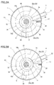
FIG. 2A is a transverse cross-sectional view of the rotary compressor ofFIG. 1 taken along the IIA-IIA line. -
FIG. 2B is a transverse cross-sectional view of the rotary compressor ofFIG. 1 taken along the IIB-IIB line. -
FIG. 3 is a diagram illustrating a flow of an oil in a compression mechanism and an oil reservoir. -
FIG. 4 is a partial longitudinal cross-sectional view of a rotary compressor according to amodification 1. -
FIG. 5 is a partial longitudinal cross-sectional view of a rotary compressor according to a modification 2. -
FIG. 6 is a partial longitudinal cross-sectional view of a rotary compressor according to amodification 3. -
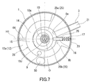
FIG. 7 is a transverse cross-sectional view of a rotary compressor according to amodification 4. - A first aspect of the present disclosure provides a rotary compressor including:
- a closed casing including an oil reservoir;
- a compression mechanism including: a cylinder; a piston disposed inside the cylinder; a vane that partitions a space formed between the cylinder and the piston into a suction chamber and a compression-discharge chamber; a suction port through which a working fluid is introduced into the suction chamber; and a discharge port through which the working fluid is discharged from the compression-discharge chamber, the compression mechanism being disposed inside the closed casing in such a manner as to be immersed in an oil held in the oil reservoir;
- a convection suppressing portion dividing the oil reservoir into a plurality of sections in a vertical direction; and
- a communication path that allows the plurality of sections of the oil reservoir to communicate with each other.
- In the rotary compressor, the communication path is located on the same side as the discharge port with respect to a reference plane, the reference plane being a plane including a central axis of the cylinder and passing through a contact line that is formed between an inner circumferential surface of the cylinder and an outer circumferential surface of the piston when the vane protrudes maximally toward the central axis of the cylinder.
- A second aspect provides the rotary compressor as set forth in the first aspect, wherein the communication path is a communication hole formed in the convection suppressing portion. Formation of the communication hole in the convection suppressing portion is easy, and is desirable from a design standpoint.
- A third aspect provides the rotary compressor as set forth in the second aspect, wherein the convection suppressing portion has two holes as the communication hole. With such a configuration, there is the potential for further reduction in the flow of the oil on the same side as the suction port with respect to the reference plane.
- A fourth aspect provides the rotary compressor as set forth in any one of the first to third aspects, wherein the convection suppressing portion includes a plate-shaped member. With such a configuration, the above-described effects can be obtained at low cost without significant design change.
- A fifth aspect provides the rotary compressor as set forth in any one of the first to fourth aspects, wherein the convection suppressing portion is formed integrally with a component of the compression mechanism. With such a configuration, the above-described effects can be obtained at low cost without significant design change.
- A sixth aspect provides the rotary compressor as set forth in any one of the first to fifth aspects, further including: a second convection suppressing portion disposed closer to a surface of the oil than the convection suppressing portion and dividing a selected one of the plurality of sections of the oil reservoir further into a plurality of sections in the vertical direction; and a second communication path that allows the plurality of sections separated by the second convection suppressing portion to communicate with each other, wherein the second communication path is located on the same side as the discharge port with respect to the reference plane. With such a configuration, the flow of the oil is further reduced on the same side as the suction port with respect to the reference plane.
- Hereinafter, an embodiment of the present invention will be described with reference to the drawings. The present invention is not limited by the embodiment given below.
- As shown in
FIG. 1 , arotary compressor 100A of the present embodiment is a hermetic compressor, and includes a closedcasing 1, a motor 7, acompression mechanism 48, and ashaft 10. Thecompression mechanism 48 has anupper muffler 33, an upper sealing member 18 (upper bearing member), afirst compression block 28, anintermediate plate 19, asecond compression block 38, a lower sealing member 24 (lower bearing member), and a lower end-face plate 34. Thecompression blocks intermediate plate 19 is disposed between thefirst compression block 28 and thesecond compression block 38. The motor 7 is disposed above theupper sealing member 18 in the closedcasing 1. Theshaft 10 extends in a vertical direction. Thecompression mechanism 48 is coupled to the motor 7 by theshaft 10. Aterminal 11 for supplying electric power to the motor 7 is provided on the top of the closedcasing 1. - The
closed casing 1 has aninternal space 13 to be filled with a refrigerant (working fluid) compressed by thecompression mechanism 48. Anoil reservoir 12 is formed at the bottom of theclosed casing 1. Asuction pipe 3, asuction pipe 4, and adischarge pipe 5 are connected to theclosed casing 1. Thesuction pipe 3 penetrates through a trunk portion of theclosed casing 1, and connects an accumulator (omitted from the drawings) to thefirst compression block 28. Thesuction pipe 4 penetrates through the trunk portion of theclosed casing 1, and connects the accumulator to thesecond compression block 38. Thesuction pipes discharge pipe 5 penetrates through the top of theclosed casing 1, and opens into theinternal space 13 of theclosed casing 1. Thedischarge pipe 5 serves to discharge the compressed refrigerant to the outside of therotary compressor 100A. - The motor 7 is composed of a
stator 7a and arotor 7b. Thestator 7a is secured to the inner circumferential surface of theclosed casing 1. Therotor 7b is secured to theshaft 10, and rotates together with theshaft 10. Anoil feed path 10d is formed in a central portion of theshaft 10. Anoil feed mechanism 10c (oil pump) that pumps up an oil of theoil reservoir 12 and feeds the oil to theoil feed path 10d is provided in a lower end portion of theshaft 10. - The
compression mechanism 48 is disposed inside theclosed casing 1 in such a manner as to be immersed in the oil held in theoil reservoir 12. In thecompression mechanism 48, thefirst compression block 28 and thesecond compression block 38 are arranged in a direction parallel to the rotation axis of theshaft 10. Thefirst compression block 28 has asuction port 8a and adischarge port 8b, and is driven by the motor 7 to draw the refrigerant through thesuction port 8a, compress the refrigerant, and then discharge the refrigerant thorough thedischarge port 8b. Thesecond compression block 38 has asuction port 8c and adischarge port 8d, and is driven by the motor 7 to draw the refrigerant through thesuction port 8c, compress the refrigerant, and then discharge the refrigerant through thedischarge port 8d. Theinternal space 13 of theclosed casing 1 is filled with the refrigerant discharged from the compression blocks 28 and 38. In the present embodiment, the structure of thefirst compression block 28 is the same as the structure of thesecond compression block 38. - As shown in
FIG. 2A and FIG. 2B , the compression blocks 28 and 38 are each composed of acylinder 14, apiston 15, avane 16, and aspring 17. A firsteccentric portion 10a and a secondeccentric portion 10b are provided in theshaft 10. The direction of the eccentricity of the firsteccentric portion 10a is 180 degrees away from the direction of the eccentricity of the secondeccentric portion 10b. That is, the phase of thepiston 15 of thefirst compression block 28 is shifted from the phase of thepiston 15 of thesecond compression block 38 by 180 degrees in terms of the rotation angle of theshaft 10. - The
piston 15 is disposed inside thecylinder 14, and is fitted to the firsteccentric portion 10a or the secondeccentric portion 10b of theshaft 10. A workingchamber 25 is formed between the inner circumferential surface of thecylinder 14 and the outer circumferential surface of thepiston 15. Avane groove 26 is formed in thecylinder 14. Thevane 16 is disposed in thevane groove 26. Aretention hole 20 opening at the outer end portion of thevane groove 26 toward both end faces of thecylinder 14 is formed at the rear of thevane groove 26. Thespring 17 is disposed in theretention hole 20 and thevane groove 26 so as to push thevane 16 toward thepiston 15. The tip of thevane 16 is in contact with the outer circumferential surface of thepiston 15. The workingchamber 25 is partitioned by thevane 16, and thus asuction chamber 25a and a compression-discharge chamber 25b are formed. Thevane 16 may be integrated with thepiston 15. That is, thepiston 15 and thevane 16 may constitute a so-called swing piston. - In the
first compression block 28, thesuction port 8a is formed in thecylinder 14. The downstream end of thesuction pipe 3 is connected to thesuction port 8a. Asuction path 21 through which the refrigerant is introduced into the workingchamber 25 from the outside of theclosed casing 1 is formed by thesuction port 8a and thesuction pipe 3. Similarly, in thesecond compression block 38, thesuction port 8c is formed in thecylinder 14. The downstream end of thesuction pipe 4 is connected to thesuction port 8c. Asuction path 22 through which the refrigerant is introduced into the workingchamber 25 from the outside of theclosed casing 1 is formed by thesuction port 8c and thesuction pipe 4. Thesuction paths shaft 10. - The
vane 16 of thesecond compression block 38 is disposed at a position (angular position) coinciding with the position of thevane 16 of thefirst compression block 28 in the circumferential direction of theshaft 10. Therefore, there is a time difference corresponding to 180 degrees between when thepiston 15 of thesecond compression block 38 is at a top dead center position (where thevane 16 is retracted maximally) and when thepiston 15 of thefirst compression block 28 is at a top dead center position. - The
upper sealing member 18 and theintermediate plate 19 seal both sides of the workingchamber 25 of thefirst compression block 28 in the vertical direction. Theintermediate plate 19 and thelower sealing member 24 seal both sides of the workingchamber 25 of thesecond compression block 38 in the vertical direction. Theupper sealing member 18 and thelower sealing member 24 function also as bearings by which theshaft 10 is rotatably supported. - The outer circumferential portion of the upper sealing
member 18 is secured to the inner circumferential surface of theclosed casing 1. By contrast, theintermediate plate 19 and thelower sealing member 24 have a diameter small enough not to seal thevane groove 26 completely. Therefore, the rearward end of thevane 16 is exposed to theoil reservoir 12 through the outer end portion of thevane groove 26. - In the present embodiment, the
discharge ports member 18 and thelower sealing member 24, respectively. That is, with respect to thefirst compression block 28, the upper sealingmember 18 corresponds to a first sealing member, and theintermediate plate 19 corresponds to a second sealing member. With respect to thesecond compression block 38, thelower sealing member 24 corresponds to the first sealing member, and theintermediate plate 19 corresponds to the second sealing member. - As shown in
FIG. 1 , arecess 18a is formed in the upper surface of the upper sealingmember 18. Therecess 18a is located in the vicinity of thevane 16 of thefirst compression block 28. Thedischarge port 8b extends from the lower surface of the upper sealingmember 18 to the bottom surface of therecess 18a. Adischarge valve 29 and astopper 30 are disposed in therecess 18a. Thedischarge valve 29 elastically deforms to open and close thedischarge port 8b. Thestopper 30 regulates the amount of deformation of thedischarge valve 29. Theupper muffler 33 is disposed above the upper sealingmember 18. Theupper muffler 33 covers thedischarge port 8b as well as the space above the upper sealingmember 18. Thedischarge port 8b communicates with theinternal space 13 of theclosed casing 1 via the space covered by theupper muffler 33. During the operation of therotary compressor 100A, the surface of the oil in theoil reservoir 12 is located generally in the vicinity of the level of the lower surface of the upper sealingmember 18. - A
recess 24a is formed in the lower surface of thelower sealing member 24. Therecess 24a is located in the vicinity of thevane 16 of thesecond compression block 38. Thedischarge port 8d extends from the upper surface of thelower sealing member 24 to the bottom surface of therecess 24a. Adischarge valve 31 and astopper 32 are disposed in therecess 24a. Thedischarge valve 31 elastically deforms to open and close thedischarge port 8d. Thestopper 32 regulates the amount of deformation of thedischarge valve 31. The lower end-face plate 34 is disposed below thelower sealing member 24. The lower end-face plate 34 seals the space communicating with thedischarge port 8d and formed in thelower sealing member 24 including therecess 24a. The space formed by the lower end-face plate 34 and thelower sealing member 24 communicates with the space covered by theupper muffler 33 through acommunication path 9 extending from thelower sealing member 24 to the upper surface of the upper sealingmember 18. That is, thedischarge port 8d communicates with theinternal space 13 of theclosed casing 1 via the space covered by the lower end-face plate 34, thecommunication path 9, and the space covered by theupper muffler 33. - The lower end-
face plate 34 extends in a direction (a radial direction of the shaft 10) perpendicular to the rotation axis of theshaft 10. In the radial direction of theshaft 10, the outer circumferential surface of the lower end-face plate 34 is located farther from the rotation axis of theshaft 10 than the outer circumferential surface of thecylinder 14, and is, for example, in contact with the inner circumferential surface of theclosed casing 1. The lower end-face plate 34 has, for example, a circular shape in plan view. The lower end-face plate 34 is provided on the exterior of thecompression mechanism 48 so as to divide theoil reservoir 12 into a plurality of sections in the vertical direction, and serves as a convection suppressing portion that suppresses convection of the oil in theoil reservoir 12. Specifically, a part of the lower end-face plate 34 serves as the convection suppressing portion. Anupper oil reservoir 12a is formed above the lower end-face plate 34, and alower oil reservoir 12b is formed below the lower end-face plate 34. Theupper oil reservoir 12a is formed around thefirst compression block 28, theintermediate plate 19, thesecond compression block 38, and thelower sealing member 24. Thelower oil reservoir 12b is located below the compression blocks 28 and 38 (compression mechanism 48). - The lower end portion of the
shaft 10 penetrates through the central portion of the lower end-face plate 34, and is exposed to thelower oil reservoir 12b. The inlet port of theoil feed mechanism 10c opens into thelower oil reservoir 12b. Theoil feed mechanism 10c draws in the oil from thelower oil reservoir 12b. - A
communication hole 50 is formed in the lower end-face plate 34. In the radial direction of theshaft 10, thecommunication hole 50 is located between the inner circumferential surface of theclosed casing 1 and the outer circumferential surface of thecylinder 14. Theupper oil reservoir 12a communicates with thelower oil reservoir 12b via thecommunication hole 50. As shown inFIG. 2A and FIG. 2B , a plane is defined as a reference plane H1, the plane including a central axis O of thecylinder 14 and passing through a contact line that is formed between the inner circumferential surface of thecylinder 14 and the outer circumferential surface of thepiston 15 when thevane 16 of the compression block 28 (or 38) protrudes maximally toward the central axis O of thecylinder 14. In this case, thecommunication hole 50 is located on the same side as thedischarge port 8b (or 8d) with respect to the reference plane H1. The central axis O of thecylinder 14 coincides with the rotation axis of theshaft 10. - Hereinafter, in the present specification, the same side as the
suction port 8a (or 8c) with respect to the reference plane H1 is referred to as a "suction side", and the same side as thedischarge port 8b (or 8d) with respect to the reference plane H1 is referred to as a "discharge side". For theupper oil reservoir 12a, its portion located on the suction side is referred to as a "suction-side portion", and its portion located on the discharge side is referred to as a "discharge-side portion". - As shown in
FIG. 3 , when an electric current is applied to the motor 7, theshaft 10 rotates so that the refrigerant is compressed in thecompression mechanism 48. The lower end portion of theshaft 10 is in contact with theoil reservoir 12. Therefore, when theshaft 10 rotates, swirling flow occurs in theoil reservoir 12. In addition, when theshaft 10 rotates, the oil of theoil reservoir 12 is fed to theoil feed path 10d by theoil feed mechanism 10c. The oil is transported upward through theoil feed path 10d, and is fed to thefirst compression block 28 and thesecond compression block 38 through transverse holes provided in the firsteccentric portion 10a and the secondeccentric portion 10b. - The oil fed to the
first compression block 28 lubricates thefirst compression block 28, then flows into a bearingportion 18b of the upper sealingmember 18, and flows out of the upper end of the bearingportion 18b to theinternal space 13 located below therotor 7b. Thereafter, the oil passes through acommunication hole 18h formed in the upper sealingmember 18, and returns to theoil reservoir 12. The oil fed to thesecond compression block 38 lubricates thesecond compression block 38, then flows into a bearingportion 24b of thelower sealing member 24, and returns to theoil reservoir 12 through the lower end of the bearingportion 24b. During the process in which the oil is fed to the compression block 28 (or 38) and returns to theoil reservoir 12, the oil receives heat from the high-temperature refrigerant in the compression block 28 (or 38) to become hot. - When the oil returns to the
oil reservoir 12 through thecommunication hole 18h of the upper sealingmember 18, the oil flows into theupper oil reservoir 12a first, then passes through thecommunication hole 50, and returns to thelower oil reservoir 12b. Therefore, the flow of the returning oil is fast in the vicinity of thecommunication hole 50, and is slow at a site distant from thecommunication hole 50. That is, a fast flow of the returning oil having a high temperature is generated on the discharge side, while the flow of the oil is reduced on the suction side. In the case of a conventional rotary compressor (see Patent Literature 1) that does not have the lower end-face plate 34 serving as the convection suppressing portion, the flow velocity of the returning oil is generally uniform around the entire compression mechanism. - Furthermore, since the
oil reservoir 12 is divided into theupper oil reservoir 12a and thelower oil reservoir 12b by the lower end-face plate 34, even when swirling flow of the oil is generated by the rotation of theshaft 10, the oil in theupper oil reservoir 12a is less likely to be affected by the swirling flow. - Therefore, the returning oil having a high temperature is less likely to pass through the suction-side portion of the
upper oil reservoir 12a. The temperature of the oil in theupper oil reservoir 12a is relatively low on the suction side, and relatively high on the discharge side. Furthermore, in the suction-side portion of theupper oil reservoir 12a, the flow of the oil is reduced, and the flow velocity of the oil is decreased. On the suction side, therefore, the heat transfer coefficients on the outer circumferential surfaces of thecylinder 14 and theintermediate plate 19 are decreased. This accordingly suppresses transfer of heat via thecylinder 14 and theintermediate plate 19 to the low-temperature refrigerant having flowed into thesuction chamber 25a. Consequently, the volumetric efficiency of therotary compressor 100A is improved, and the performance of a refrigeration cycle apparatus using therotary compressor 100A is enhanced. - The position and number of holes serving as the
communication hole 18h in the upper sealingmember 18 are not particularly limited. In general, a plurality ofcommunication holes 18h are formed at regular angular intervals in the circumferential direction of theshaft 10 so that the oil can quickly return to theoil reservoir 12. - In the present embodiment, the lower end-
face plate 34 is in contact with theclosed casing 1. Specifically, the outer circumferential surface of the lower end-face plate 34 may be in contact with theclosed casing 1 over the entire circumference, or a part of the outer circumferential surface of the lower end-face plate 34 may be in contact with theclosed casing 1. However, it is not essential that the lower end-face plate 34 be in contact with theclosed casing 1. A slight gap may be formed between the outer circumferential surface of the lower end-face plate 34 and theclosed casing 1. In this case, it becomes easy to assemble therotary compressor 100A. In addition, the slight gap can function as a passage for the refrigerant when the refrigerant dissolved in the oil forms into gas bubbles due to change in the operating conditions of therotary compressor 100A. It is possible to avoid a situation where the gas refrigerant is accumulated in thelower oil reservoir 12b or theoil feed mechanism 10c draws in the gas refrigerant. - In the present embodiment, only one
communication hole 50 is provided on the discharge side. Theentire communication hole 50 is located on the discharged side. On the discharge side, however, a plurality of communication holes 50 may be formed in the lower end-face plate 34. In this case, there is the potential for further reduction in the flow of the oil in the suction-side portion of theupper oil reservoir 12a. - The means for allowing the
upper oil reservoir 12a and thelower oil reservoir 12b to communicate with each other is not limited to thecommunication hole 50. For example, when a relatively large cut is formed in the outer circumferential portion of the lower end-face plate 34, such a cut can be used, instead of thecommunication hole 50, as a communication path that allows theupper oil reservoir 12a and thelower oil reservoir 12b to communicate with each other. However, formation of thecommunication hole 50 in the lower end-face plate 34 is easy, and is desirable from a design standpoint. - In the present embodiment, the lower end-
face plate 34 serving as the convection suppressing portion is a plate-shaped member. The lower end-face plate 34 for covering the space below thelower sealing member 24 is used as the convection suppressing portion. Specifically, the outer circumferential portion of the lower end-face plate 34 serves as the convection suppressing portion. The lower end-face plate 34 is a component of thecompression mechanism 48. That is, the convection suppressing portion is formed integrally with a component of thecompression mechanism 48. With such a configuration, the above-described effects can be obtained at low cost without significant design change. - Hereinafter, several modifications will be described. For the modifications given below, the same components as those described with reference to
FIG. 1 to FIG. 3 are denoted by the same reference characters, and descriptions thereof are omitted. - As shown in
FIG. 4 , arotary compressor 100B according to amodification 1 includes alower sealing member 44 serving as the convection suppressing portion. Thelower sealing member 44 has aflange portion 44a extending outwardly in the radial direction of theshaft 10. Theflange portion 44a has a ring shape in plan view. Therecess 24a of thelower sealing member 44 is closed by a lower end-face plate 45. In the present modification, the lower end-face plate 45 has a size that is necessary and sufficient for closing therecess 24a of thelower sealing member 44. The outer diameter of the lower end-face plate 45 is, for example, equal to the outer diameter of thecylinder 14. - The
communication hole 50 is formed in theflange portion 44a of thelower sealing member 44. Theupper oil reservoir 12a communicates with thelower oil reservoir 12b through thecommunication hole 50. The outer circumferential surface of theflange portion 44a of thelower sealing member 44 may be in contact with theclosed casing 1 over the entire circumference, or a part of the outer circumferential surface may be in contact with theclosed casing 1. A slight gap may be formed between the outer circumferential surface of theflange portion 44a and theclosed casing 1. This is as described in the above embodiment. - As shown in
FIG. 5 , arotary compressor 100C according to a modification 2 includes a lower end-face plate 54 (convection suppressing portion) having acircular plate portion 54a and anozzle portion 54b. Therecess 24a of thelower sealing member 24 is closed by thecircular plate portion 54a. The outer circumferential surface of thecircular plate portion 54a is, for example, in contact with the inner circumferential surface of theclosed casing 1. That is, thecircular plate portion 54a has the same structure as the lower end-face plate 34 described with reference toFIG. 1 to FIG. 3 . Thenozzle portion 54b is provided in the outer circumferential portion of thecircular plate portion 54a, and extends upwardly in the vertical direction. The upper open end of thenozzle portion 54b is located in theupper oil reservoir 12a. Thecommunication hole 50 is formed inside thenozzle portion 54b. - According to the present modification, the returning oil flows into the
upper oil reservoir 12a through thecommunication hole 18h of the upper sealingmember 18, passes through thenozzle portion 54b (communication hole 50), and moves to thelower oil reservoir 12b. That is, in the present modification, the flow of the returning oil is further restricted compared to the case of the above embodiment. The convection of the oil in the suction-side portion of theupper oil reservoir 12a is further suppressed. According to the present modification, the effect of reducing heat reception by the drawn refrigerant is larger than that in the above embodiment. Consequently, the performance of a refrigeration cycle apparatus using therotary compressor 100C is further enhanced. - As shown in
FIG. 6 , arotary compressor 100D according to amodification 3 includes anintermediate plate 39 serving as the convection suppressing portion. Except for theintermediate plate 39, therotary compressor 100D has approximately the same structure as therotary compressor 100A described above. - In the present modification, the
intermediate plate 39 extends outwardly in the radial direction of theshaft 10. A narrow gap is formed between the outer circumferential surface of theintermediate plate 39 and the inner circumferential surface of theclosed casing 1. Theupper oil reservoir 12a is divided into anintermediate oil reservoir 12c and anuppermost oil reservoir 12d by theintermediate plate 39. That is, theintermediate plate 39 serves as a second convection suppressing portion disposed closer to the surface of the oil than the lower end-face plate 34 (first convection suppressing portion) so that a selected one of the plurality ofsections oil reservoir 12 is divided further into the plurality ofsections - A
second communication hole 51 is formed in the outer circumferential portion of theintermediate plate 39. Theuppermost oil reservoir 12d communicates with theintermediate oil reservoir 12c via thesecond communication hole 51. That is, thesecond communication hole 51 serves as a second communication path that allows the plurality ofsections second communication hole 51 is also located on the discharge side. When thecommunication hole 50 and thesecond communication hole 51 are projected onto a plane perpendicular to the rotation axis of theshaft 10, the projection of thecommunication hole 50 overlaps the projection of thesecond communication hole 51. That is, thesecond communication hole 51 is formed at approximately the same position as thecommunication hole 50 in the circumferential direction of theshaft 10. - When the oil returns to the
oil reservoir 12 through thecommunication hole 18h of the upper sealingmember 18, the oil flows into theuppermost oil reservoir 12d first, then passes through thesecond communication hole 51, and flows into theintermediate oil reservoir 12c. Thereafter, the oil passes through thecommunication hole 50, and returns to thelower oil reservoir 12b. Therefore, the flow of the returning oil is fast in the vicinity of the communication holes 50 and 51, and is slow at a site distant from the communication holes 50 and 51. In theintermediate oil reservoir 12c, the oil flows principally along a straight line connecting thecommunication hole 50 to thesecond communication path 51 even when the returning oil having a high temperature flows into theuppermost oil reservoir 12d from all sides of theshaft 10 uniformly. Therefore, the flow of the oil is further reduced on the suction side compared to the case of the above embodiment. - Thus, the returning oil having a high temperature is less likely to pass through the suction-side portion of the
uppermost oil reservoir 12d. The flow of the oil in the suction-side portion of theintermediate oil reservoir 12c is very slow. Therefore, the temperature of the suction-side portion of theintermediate oil reservoir 12c can be made lower than the temperature of the discharge-side portion of theupper oil reservoir 12a and the temperature of thelower oil reservoir 12b. - Furthermore, in the suction-side portion of the
intermediate oil reservoir 12c, the flow of the oil is reduced, and the flow velocity of the oil is decreased. On the suction side, therefore, the heat transfer coefficients on the outer circumferential surface of thecylinder 14 and the surface of theintermediate plate 39 are decreased. This accordingly suppresses transfer of heat via thecylinder 14 and theintermediate plate 39 to the low-temperature refrigerant having flowed into thesuction chamber 25a. Consequently, the volumetric efficiency of therotary compressor 100D is improved, and the performance of a refrigeration cycle apparatus using therotary compressor 100D is enhanced. - As shown in
FIG. 7 , a rotary compressor 100E according to amodification 4 includes the components of therotary compressor 100A described above, and additionally includes a convection suppressing portion 64 (third convection suppressing portion) that suppresses convection of the oil in theoil reservoir 12. Except for theconvection suppressing portion 64, the rotary compressor 100E has the same structure as therotary compressor 100A. - The
convection suppressing portion 64 is formed integrally with thecylinder 14 in such a manner as to protrude outwardly from the outer circumferential surface of thecylinder 14. Theconvection suppressing portion 64 divides theupper oil reservoir 12a in the circumferential direction of theshaft 10. Theupper oil reservoir 12a is divided into a suction-side portion and a discharge-side portion by theconvection suppressing portion 64. Theconvection suppressing portion 64 is provided, for example, at such a position that theconvection suppressing portion 64 lies in the reference plane H1. In the radial direction of theshaft 10, the outer circumferential surface of theconvection suppressing portion 64 may be in contact with the inner circumferential surface of theclosed casing 1 or may be slightly away from the inner circumferential surface of theclosed casing 1. With theconvection suppressing portion 64, the flow of the oil in the suction-side portion of theupper oil reservoir 12a is further reduced. - Each of the
rotary compressors 100A to 100E described in the present specification is a two-piston rotary compressor including the compression blocks 28 and 38. However, the number of the compression blocks is not particularly limited. That is, the techniques disclosed in the present specification can be applied also to a one-piston rotary compressor, and can be applied also to a rotary compressor including three or more compression blocks. - The present invention is useful for compressors of refrigeration cycle apparatuses that can be used in electrical appliances such as hot water dispensers, hot-water heaters, and air conditioners.
Claims (6)
- A rotary compressor comprising:a closed casing (1) comprising an oil reservoir (12);a compression mechanism (48) comprising: a cylinder (14) ; a piston (15) disposed inside the cylinder; a vane (16) that partitions a space formed between the cylinder and the piston into a suction chamber and a compression-discharge chamber; a suction port through which a working fluid is introduced into the suction chamber; and a discharge port through which the working fluid is discharged from the compression-discharge chamber, the compression mechanism being disposed inside the closed casing in such a manner as to be immersed in an oil held in the oil reservoir;a convection suppressing portion dividing the oil reservoir into a plurality of sections in a vertical direction; anda communication path that allows the plurality of sections of the oil reservoir to communicate with each other, characterised in thatthe communication path (50) is located on the same side as the discharge port (8b;8d) with respect to a reference plane (H1) the reference plane being a plane including a central axis (O) of the cylinder (14) and passing through a contact line that is formed between an inner circumferential surface of the cylinder and an outer circumferential surface of the piston when the vane protrudes maximally toward the central axis of the cylinder.
- The rotary compressor according to claim 1, wherein the communication path is a communication hole formed in the convection suppressing portion.
- The rotary compressor according to claim 2, wherein the convection suppressing portion has two or more holes as the communication hole.
- The rotary compressor according to claim 1, wherein the convection suppressing portion comprises a plate-shaped member.
- The rotary compressor according to claim 1, wherein the convection suppressing portion is formed integrally with a component of the compression mechanism.
- The rotary compressor according to claim 1, further comprising:a second convection suppressing portion disposed closer to a surface of the oil than the convection suppressing portion and dividing a selected one of the plurality of sections of the oil reservoir further into a plurality of sections in the vertical direction; anda second communication path that allows the plurality of sections separated by the second convection suppressing portion to communicate with each other, whereinthe second communication path is located on the same side as the discharge port with respect to the reference plane.
Applications Claiming Priority (2)
| Application Number | Priority Date | Filing Date | Title |
|---|---|---|---|
| JP2012153808 | 2012-07-09 | ||
| PCT/JP2013/004107 WO2014010199A1 (en) | 2012-07-09 | 2013-07-02 | Rotary compressor |
Publications (3)
| Publication Number | Publication Date |
|---|---|
| EP2871366A1 EP2871366A1 (en) | 2015-05-13 |
| EP2871366A4 EP2871366A4 (en) | 2015-07-22 |
| EP2871366B1 true EP2871366B1 (en) | 2016-09-07 |
Family
ID=49915683
Family Applications (1)
| Application Number | Title | Priority Date | Filing Date |
|---|---|---|---|
| EP13817101.2A Not-in-force EP2871366B1 (en) | 2012-07-09 | 2013-07-02 | Rotary compressor |
Country Status (5)
| Country | Link |
|---|---|
| US (1) | US9695825B2 (en) |
| EP (1) | EP2871366B1 (en) |
| JP (1) | JP6115872B2 (en) |
| CN (1) | CN103782038B (en) |
| WO (1) | WO2014010199A1 (en) |
Families Citing this family (5)
| Publication number | Priority date | Publication date | Assignee | Title |
|---|---|---|---|---|
| TWI743126B (en) * | 2016-07-08 | 2021-10-21 | 瑞士商雀巢製品股份有限公司 | Rotary compressor arrangement |
| JP2018009534A (en) * | 2016-07-14 | 2018-01-18 | 株式会社富士通ゼネラル | Rotary Compressor |
| WO2020161965A1 (en) * | 2019-02-07 | 2020-08-13 | 東芝キヤリア株式会社 | Rotary compressor, method for manufacturing rotary compressor, and refrigeration cycle device |
| CN112610490B (en) * | 2020-12-29 | 2022-05-27 | 珠海格力电器股份有限公司 | Pump body assembly and fluid machine |
| CN113503341B (en) * | 2021-09-10 | 2021-11-19 | 江苏亚雄减速机械有限公司 | Hydraulic cylinder gear shifting speed reducer |
Family Cites Families (14)
| Publication number | Priority date | Publication date | Assignee | Title |
|---|---|---|---|---|
| JPS60173388A (en) * | 1984-02-20 | 1985-09-06 | Mitsubishi Electric Corp | Enclosed rotary electric compressor |
| JPS60134882U (en) * | 1984-02-21 | 1985-09-07 | 三菱電機株式会社 | Hermetic rotary compressor |
| JPH0346237Y2 (en) * | 1985-06-13 | 1991-09-30 | ||
| JPS62137393U (en) * | 1986-02-25 | 1987-08-29 | ||
| JPH02140486A (en) * | 1988-11-22 | 1990-05-30 | Mitsubishi Electric Corp | Rotary compressor |
| JP2002221180A (en) * | 2001-01-26 | 2002-08-09 | Sanyo Electric Co Ltd | Rotary compressor |
| JP2004251129A (en) * | 2003-02-18 | 2004-09-09 | Matsushita Electric Ind Co Ltd | Rotary compressor |
| KR101234824B1 (en) * | 2005-01-18 | 2013-02-20 | 삼성전자주식회사 | Multi-stage compression type rotary compressor |
| WO2007138809A1 (en) * | 2006-05-26 | 2007-12-06 | Panasonic Corporation | Expander and compressor with integrated expander |
| US8316664B2 (en) | 2007-05-16 | 2012-11-27 | Panasonic Corporation | Refrigeration cycle apparatus and fluid machine used therefor |
| US20100275638A1 (en) | 2008-05-08 | 2010-11-04 | Panasonic Corporation | Fluid machine |
| JP2010190182A (en) * | 2009-02-20 | 2010-09-02 | Sanyo Electric Co Ltd | Sealed type rotary compressor |
| KR20120015843A (en) | 2010-08-13 | 2012-02-22 | 삼성전자주식회사 | Variable capacity rotary compressor and air conditioning system |
| WO2012090345A1 (en) * | 2010-12-27 | 2012-07-05 | 三菱電機株式会社 | Refrigerant compressor |
-
2013
- 2013-07-02 CN CN201380002951.6A patent/CN103782038B/en not_active Expired - Fee Related
- 2013-07-02 JP JP2014524629A patent/JP6115872B2/en active Active
- 2013-07-02 EP EP13817101.2A patent/EP2871366B1/en not_active Not-in-force
- 2013-07-02 WO PCT/JP2013/004107 patent/WO2014010199A1/en active Application Filing
- 2013-07-02 US US14/342,693 patent/US9695825B2/en not_active Expired - Fee Related
Also Published As
| Publication number | Publication date |
|---|---|
| JP6115872B2 (en) | 2017-04-19 |
| EP2871366A4 (en) | 2015-07-22 |
| EP2871366A1 (en) | 2015-05-13 |
| WO2014010199A1 (en) | 2014-01-16 |
| JPWO2014010199A1 (en) | 2016-06-20 |
| CN103782038A (en) | 2014-05-07 |
| CN103782038B (en) | 2016-08-17 |
| US9695825B2 (en) | 2017-07-04 |
| US20140219851A1 (en) | 2014-08-07 |
Similar Documents
| Publication | Publication Date | Title |
|---|---|---|
| EP2796721B1 (en) | Rotary compressor | |
| EP2871366B1 (en) | Rotary compressor | |
| JP4422208B2 (en) | Expander integrated compressor | |
| JP5586537B2 (en) | Rotary two-stage compressor | |
| US9004888B2 (en) | Rotary compressor having discharge groove to communicate compression chamber with discharge port near vane groove | |
| EP2693056B1 (en) | Scroll compressor | |
| JP5366884B2 (en) | Vane rotary compressor | |
| US9689388B2 (en) | Scroll compressor | |
| EP2781757B1 (en) | Rotary compressor | |
| US9512841B2 (en) | Rotary compressor with oil retaining portion | |
| JP5430393B2 (en) | Vane type compressor | |
| JP6127722B2 (en) | Rotary compressor | |
| CN210599411U (en) | Closed compressor | |
| CN215292888U (en) | Rotary compressor | |
| KR20150081142A (en) | A rotary compressor | |
| JP2014009612A (en) | Rotary compressor | |
| US20230137362A1 (en) | Rotary compressor | |
| JP6123488B2 (en) | Rotary compressor | |
| JP5824665B2 (en) | Hermetic compressor | |
| JP6043949B2 (en) | Compressor | |
| KR20130081107A (en) | Hemetic compressor | |
| KR20080067261A (en) | Scroll compressor | |
| JP2016089811A (en) | Rotary compressor | |
| JP2014025408A (en) | Rotary compressor |
Legal Events
| Date | Code | Title | Description |
|---|---|---|---|
| PUAI | Public reference made under article 153(3) epc to a published international application that has entered the european phase |
Free format text: ORIGINAL CODE: 0009012 |
|
| 17P | Request for examination filed |
Effective date: 20150209 |
|
| AK | Designated contracting states |
Kind code of ref document: A1 Designated state(s): AL AT BE BG CH CY CZ DE DK EE ES FI FR GB GR HR HU IE IS IT LI LT LU LV MC MK MT NL NO PL PT RO RS SE SI SK SM TR |
|
| AX | Request for extension of the european patent |
Extension state: BA ME |
|
| RA4 | Supplementary search report drawn up and despatched (corrected) |
Effective date: 20150624 |
|
| RIC1 | Information provided on ipc code assigned before grant |
Ipc: F04C 18/356 20060101ALI20150618BHEP Ipc: F04C 23/00 20060101ALI20150618BHEP Ipc: F04C 29/02 20060101AFI20150618BHEP Ipc: F04C 29/04 20060101ALI20150618BHEP |
|
| DAX | Request for extension of the european patent (deleted) | ||
| GRAP | Despatch of communication of intention to grant a patent |
Free format text: ORIGINAL CODE: EPIDOSNIGR1 |
|
| INTG | Intention to grant announced |
Effective date: 20160219 |
|
| GRAS | Grant fee paid |
Free format text: ORIGINAL CODE: EPIDOSNIGR3 |
|
| GRAA | (expected) grant |
Free format text: ORIGINAL CODE: 0009210 |
|
| AK | Designated contracting states |
Kind code of ref document: B1 Designated state(s): AL AT BE BG CH CY CZ DE DK EE ES FI FR GB GR HR HU IE IS IT LI LT LU LV MC MK MT NL NO PL PT RO RS SE SI SK SM TR |
|
| REG | Reference to a national code |
Ref country code: GB Ref legal event code: FG4D |
|
| REG | Reference to a national code |
Ref country code: CH Ref legal event code: EP |
|
| REG | Reference to a national code |
Ref country code: IE Ref legal event code: FG4D |
|
| REG | Reference to a national code |
Ref country code: DE Ref legal event code: R096 Ref document number: 602013011257 Country of ref document: DE |
|
| REG | Reference to a national code |
Ref country code: AT Ref legal event code: REF Ref document number: 827148 Country of ref document: AT Kind code of ref document: T Effective date: 20161015 |
|
| REG | Reference to a national code |
Ref country code: LT Ref legal event code: MG4D |
|
| REG | Reference to a national code |
Ref country code: NL Ref legal event code: MP Effective date: 20160907 |
|
| PG25 | Lapsed in a contracting state [announced via postgrant information from national office to epo] |
Ref country code: LT Free format text: LAPSE BECAUSE OF FAILURE TO SUBMIT A TRANSLATION OF THE DESCRIPTION OR TO PAY THE FEE WITHIN THE PRESCRIBED TIME-LIMIT Effective date: 20160907 Ref country code: FI Free format text: LAPSE BECAUSE OF FAILURE TO SUBMIT A TRANSLATION OF THE DESCRIPTION OR TO PAY THE FEE WITHIN THE PRESCRIBED TIME-LIMIT Effective date: 20160907 Ref country code: NO Free format text: LAPSE BECAUSE OF FAILURE TO SUBMIT A TRANSLATION OF THE DESCRIPTION OR TO PAY THE FEE WITHIN THE PRESCRIBED TIME-LIMIT Effective date: 20161207 Ref country code: RS Free format text: LAPSE BECAUSE OF FAILURE TO SUBMIT A TRANSLATION OF THE DESCRIPTION OR TO PAY THE FEE WITHIN THE PRESCRIBED TIME-LIMIT Effective date: 20160907 Ref country code: HR Free format text: LAPSE BECAUSE OF FAILURE TO SUBMIT A TRANSLATION OF THE DESCRIPTION OR TO PAY THE FEE WITHIN THE PRESCRIBED TIME-LIMIT Effective date: 20160907 |
|
| REG | Reference to a national code |
Ref country code: AT Ref legal event code: MK05 Ref document number: 827148 Country of ref document: AT Kind code of ref document: T Effective date: 20160907 |
|
| PG25 | Lapsed in a contracting state [announced via postgrant information from national office to epo] |
Ref country code: GR Free format text: LAPSE BECAUSE OF FAILURE TO SUBMIT A TRANSLATION OF THE DESCRIPTION OR TO PAY THE FEE WITHIN THE PRESCRIBED TIME-LIMIT Effective date: 20161208 Ref country code: NL Free format text: LAPSE BECAUSE OF FAILURE TO SUBMIT A TRANSLATION OF THE DESCRIPTION OR TO PAY THE FEE WITHIN THE PRESCRIBED TIME-LIMIT Effective date: 20160907 Ref country code: ES Free format text: LAPSE BECAUSE OF FAILURE TO SUBMIT A TRANSLATION OF THE DESCRIPTION OR TO PAY THE FEE WITHIN THE PRESCRIBED TIME-LIMIT Effective date: 20160907 Ref country code: LV Free format text: LAPSE BECAUSE OF FAILURE TO SUBMIT A TRANSLATION OF THE DESCRIPTION OR TO PAY THE FEE WITHIN THE PRESCRIBED TIME-LIMIT Effective date: 20160907 Ref country code: SE Free format text: LAPSE BECAUSE OF FAILURE TO SUBMIT A TRANSLATION OF THE DESCRIPTION OR TO PAY THE FEE WITHIN THE PRESCRIBED TIME-LIMIT Effective date: 20160907 |
|
| PG25 | Lapsed in a contracting state [announced via postgrant information from national office to epo] |
Ref country code: RO Free format text: LAPSE BECAUSE OF FAILURE TO SUBMIT A TRANSLATION OF THE DESCRIPTION OR TO PAY THE FEE WITHIN THE PRESCRIBED TIME-LIMIT Effective date: 20160907 Ref country code: EE Free format text: LAPSE BECAUSE OF FAILURE TO SUBMIT A TRANSLATION OF THE DESCRIPTION OR TO PAY THE FEE WITHIN THE PRESCRIBED TIME-LIMIT Effective date: 20160907 |
|
| PG25 | Lapsed in a contracting state [announced via postgrant information from national office to epo] |
Ref country code: BE Free format text: LAPSE BECAUSE OF FAILURE TO SUBMIT A TRANSLATION OF THE DESCRIPTION OR TO PAY THE FEE WITHIN THE PRESCRIBED TIME-LIMIT Effective date: 20160907 Ref country code: PL Free format text: LAPSE BECAUSE OF FAILURE TO SUBMIT A TRANSLATION OF THE DESCRIPTION OR TO PAY THE FEE WITHIN THE PRESCRIBED TIME-LIMIT Effective date: 20160907 Ref country code: PT Free format text: LAPSE BECAUSE OF FAILURE TO SUBMIT A TRANSLATION OF THE DESCRIPTION OR TO PAY THE FEE WITHIN THE PRESCRIBED TIME-LIMIT Effective date: 20170109 Ref country code: IS Free format text: LAPSE BECAUSE OF FAILURE TO SUBMIT A TRANSLATION OF THE DESCRIPTION OR TO PAY THE FEE WITHIN THE PRESCRIBED TIME-LIMIT Effective date: 20170107 Ref country code: AT Free format text: LAPSE BECAUSE OF FAILURE TO SUBMIT A TRANSLATION OF THE DESCRIPTION OR TO PAY THE FEE WITHIN THE PRESCRIBED TIME-LIMIT Effective date: 20160907 Ref country code: SK Free format text: LAPSE BECAUSE OF FAILURE TO SUBMIT A TRANSLATION OF THE DESCRIPTION OR TO PAY THE FEE WITHIN THE PRESCRIBED TIME-LIMIT Effective date: 20160907 Ref country code: CZ Free format text: LAPSE BECAUSE OF FAILURE TO SUBMIT A TRANSLATION OF THE DESCRIPTION OR TO PAY THE FEE WITHIN THE PRESCRIBED TIME-LIMIT Effective date: 20160907 Ref country code: BG Free format text: LAPSE BECAUSE OF FAILURE TO SUBMIT A TRANSLATION OF THE DESCRIPTION OR TO PAY THE FEE WITHIN THE PRESCRIBED TIME-LIMIT Effective date: 20161207 Ref country code: SM Free format text: LAPSE BECAUSE OF FAILURE TO SUBMIT A TRANSLATION OF THE DESCRIPTION OR TO PAY THE FEE WITHIN THE PRESCRIBED TIME-LIMIT Effective date: 20160907 |
|
| REG | Reference to a national code |
Ref country code: DE Ref legal event code: R097 Ref document number: 602013011257 Country of ref document: DE |
|
| PG25 | Lapsed in a contracting state [announced via postgrant information from national office to epo] |
Ref country code: IT Free format text: LAPSE BECAUSE OF FAILURE TO SUBMIT A TRANSLATION OF THE DESCRIPTION OR TO PAY THE FEE WITHIN THE PRESCRIBED TIME-LIMIT Effective date: 20160907 |
|
| PLBE | No opposition filed within time limit |
Free format text: ORIGINAL CODE: 0009261 |
|
| STAA | Information on the status of an ep patent application or granted ep patent |
Free format text: STATUS: NO OPPOSITION FILED WITHIN TIME LIMIT |
|
| PG25 | Lapsed in a contracting state [announced via postgrant information from national office to epo] |
Ref country code: DK Free format text: LAPSE BECAUSE OF FAILURE TO SUBMIT A TRANSLATION OF THE DESCRIPTION OR TO PAY THE FEE WITHIN THE PRESCRIBED TIME-LIMIT Effective date: 20160907 |
|
| 26N | No opposition filed |
Effective date: 20170608 |
|
| PG25 | Lapsed in a contracting state [announced via postgrant information from national office to epo] |
Ref country code: SI Free format text: LAPSE BECAUSE OF FAILURE TO SUBMIT A TRANSLATION OF THE DESCRIPTION OR TO PAY THE FEE WITHIN THE PRESCRIBED TIME-LIMIT Effective date: 20160907 |
|
| REG | Reference to a national code |
Ref country code: CH Ref legal event code: PL |
|
| GBPC | Gb: european patent ceased through non-payment of renewal fee |
Effective date: 20170702 |
|
| REG | Reference to a national code |
Ref country code: IE Ref legal event code: MM4A |
|
| REG | Reference to a national code |
Ref country code: FR Ref legal event code: ST Effective date: 20180330 |
|
| PG25 | Lapsed in a contracting state [announced via postgrant information from national office to epo] |
Ref country code: IE Free format text: LAPSE BECAUSE OF NON-PAYMENT OF DUE FEES Effective date: 20170702 Ref country code: GB Free format text: LAPSE BECAUSE OF NON-PAYMENT OF DUE FEES Effective date: 20170702 Ref country code: CH Free format text: LAPSE BECAUSE OF NON-PAYMENT OF DUE FEES Effective date: 20170731 Ref country code: LI Free format text: LAPSE BECAUSE OF NON-PAYMENT OF DUE FEES Effective date: 20170731 |
|
| PG25 | Lapsed in a contracting state [announced via postgrant information from national office to epo] |
Ref country code: FR Free format text: LAPSE BECAUSE OF NON-PAYMENT OF DUE FEES Effective date: 20170731 |
|
| PG25 | Lapsed in a contracting state [announced via postgrant information from national office to epo] |
Ref country code: LU Free format text: LAPSE BECAUSE OF NON-PAYMENT OF DUE FEES Effective date: 20170702 |
|
| PG25 | Lapsed in a contracting state [announced via postgrant information from national office to epo] |
Ref country code: MT Free format text: LAPSE BECAUSE OF NON-PAYMENT OF DUE FEES Effective date: 20170702 |
|
| PG25 | Lapsed in a contracting state [announced via postgrant information from national office to epo] |
Ref country code: AL Free format text: LAPSE BECAUSE OF FAILURE TO SUBMIT A TRANSLATION OF THE DESCRIPTION OR TO PAY THE FEE WITHIN THE PRESCRIBED TIME-LIMIT Effective date: 20160907 |
|
| PGFP | Annual fee paid to national office [announced via postgrant information from national office to epo] |
Ref country code: DE Payment date: 20180723 Year of fee payment: 6 |
|
| PG25 | Lapsed in a contracting state [announced via postgrant information from national office to epo] |
Ref country code: MC Free format text: LAPSE BECAUSE OF FAILURE TO SUBMIT A TRANSLATION OF THE DESCRIPTION OR TO PAY THE FEE WITHIN THE PRESCRIBED TIME-LIMIT Effective date: 20160907 Ref country code: HU Free format text: LAPSE BECAUSE OF FAILURE TO SUBMIT A TRANSLATION OF THE DESCRIPTION OR TO PAY THE FEE WITHIN THE PRESCRIBED TIME-LIMIT; INVALID AB INITIO Effective date: 20130702 |
|
| PG25 | Lapsed in a contracting state [announced via postgrant information from national office to epo] |
Ref country code: CY Free format text: LAPSE BECAUSE OF FAILURE TO SUBMIT A TRANSLATION OF THE DESCRIPTION OR TO PAY THE FEE WITHIN THE PRESCRIBED TIME-LIMIT Effective date: 20160907 |
|
| PG25 | Lapsed in a contracting state [announced via postgrant information from national office to epo] |
Ref country code: MK Free format text: LAPSE BECAUSE OF FAILURE TO SUBMIT A TRANSLATION OF THE DESCRIPTION OR TO PAY THE FEE WITHIN THE PRESCRIBED TIME-LIMIT Effective date: 20160907 |
|
| REG | Reference to a national code |
Ref country code: DE Ref legal event code: R119 Ref document number: 602013011257 Country of ref document: DE |
|
| PG25 | Lapsed in a contracting state [announced via postgrant information from national office to epo] |
Ref country code: TR Free format text: LAPSE BECAUSE OF FAILURE TO SUBMIT A TRANSLATION OF THE DESCRIPTION OR TO PAY THE FEE WITHIN THE PRESCRIBED TIME-LIMIT Effective date: 20160907 |
|
| PG25 | Lapsed in a contracting state [announced via postgrant information from national office to epo] |
Ref country code: DE Free format text: LAPSE BECAUSE OF NON-PAYMENT OF DUE FEES Effective date: 20200201 |