EP2871328A1 - Variable nozzle turbocharger - Google Patents
Variable nozzle turbocharger Download PDFInfo
- Publication number
- EP2871328A1 EP2871328A1 EP20140192318 EP14192318A EP2871328A1 EP 2871328 A1 EP2871328 A1 EP 2871328A1 EP 20140192318 EP20140192318 EP 20140192318 EP 14192318 A EP14192318 A EP 14192318A EP 2871328 A1 EP2871328 A1 EP 2871328A1
- Authority
- EP
- European Patent Office
- Prior art keywords
- unison ring
- projections
- facing surface
- circumferential direction
- main plate
- Prior art date
- Legal status (The legal status is an assumption and is not a legal conclusion. Google has not performed a legal analysis and makes no representation as to the accuracy of the status listed.)
- Granted
Links
Images



Classifications
-
- F—MECHANICAL ENGINEERING; LIGHTING; HEATING; WEAPONS; BLASTING
- F01—MACHINES OR ENGINES IN GENERAL; ENGINE PLANTS IN GENERAL; STEAM ENGINES
- F01D—NON-POSITIVE DISPLACEMENT MACHINES OR ENGINES, e.g. STEAM TURBINES
- F01D17/00—Regulating or controlling by varying flow
- F01D17/10—Final actuators
- F01D17/12—Final actuators arranged in stator parts
- F01D17/14—Final actuators arranged in stator parts varying effective cross-sectional area of nozzles or guide conduits
- F01D17/16—Final actuators arranged in stator parts varying effective cross-sectional area of nozzles or guide conduits by means of nozzle vanes
- F01D17/165—Final actuators arranged in stator parts varying effective cross-sectional area of nozzles or guide conduits by means of nozzle vanes for radial flow, i.e. the vanes turning around axes which are essentially parallel to the rotor centre line
-
- F—MECHANICAL ENGINEERING; LIGHTING; HEATING; WEAPONS; BLASTING
- F05—INDEXING SCHEMES RELATING TO ENGINES OR PUMPS IN VARIOUS SUBCLASSES OF CLASSES F01-F04
- F05D—INDEXING SCHEME FOR ASPECTS RELATING TO NON-POSITIVE-DISPLACEMENT MACHINES OR ENGINES, GAS-TURBINES OR JET-PROPULSION PLANTS
- F05D2220/00—Application
- F05D2220/40—Application in turbochargers
Definitions
- the present invention relates to a variable nozzle turbocharger.
- JP 2010-180864 A describes a variable nozzle turbocharger including a variable nozzle provided in an exhaust passage for blowing exhaust gas to a turbine wheel and configured such that its opening degree is changed so as to adjust a flow speed of the exhaust gas.
- a change operation of the opening degree of the variable nozzle is performed by rotation (circumferential displacement) of a unison ring aligned with a main plate provided in the exhaust passage, in a thickness direction of the main plate.
- variable nozzle turbocharger In the variable nozzle turbocharger, the unison ring and the main plate are exposed to the exhaust gas. Because of this, foreign substances such as soot included in the exhaust gas may be accumulated between the unison ring and the main plate. The foreign substances thus accumulated disturb the circumferential displacement of the unison ring, thereby resulting in that an appropriate operation of the variable nozzle may be disturbed by the foreign substances.
- the present invention provides a variable nozzle turbocharger that is able to restrain that an appropriate operation of a variable nozzle is disturbed by foreign substances accumulated between a unison ring and a main plate.
- a variable nozzle turbocharger is a variable nozzle turbocharger for changing a flow speed of exhaust gas to be blown to a turbine wheel and characterized by including a main plate, a unison ring, and variable nozzles.
- the unison ring is aligned with the main plate in a thickness direction of the main plate.
- the variable nozzles are configured such that their opening degrees are changed along with rotation of the unison ring.
- a first facing surface of the unison ring is opposed to a second facing surface of the main plate via a gap, and the first facing surface is provided with a plurality of first projections projecting toward the second facing surface and placed at intervals along a circumferential direction of the unison ring.
- the first facing surface may include a plurality of first recessed portions placed at intervals in the circumferential direction of the unison ring, and the plurality of first projections and the plurality of first recessed portions may be alternately arranged on the first facing surface along with the circumferential direction of the unison ring. According to the above configuration, the foreign substances attached to the gap can be effectively scraped out from the gap by the plurality of first projections provided between the first facing surface and the second facing surface.
- the second facing surface may include a plurality of second recessed portions placed at intervals in the circumferential direction of the unison ring, and the plurality of second recessed portions may be opposed to the plurality of first recessed portions provided on the first facing surface.
- the second facing surface may include a plurality of second recessed portions placed at intervals in the circumferential direction of the unison ring, and may include a plurality of second projections placed at intervals in the circumferential direction of the unison ring, the plurality of second projections and the plurality of second recessed portions may be alternately arranged on the second facing surface along with the circumferential direction of the unison ring, the plurality of first projections provided on the first facing surface may be inserted into the plurality of second recessed portions, and the plurality of second projections may be inserted into the plurality of first recessed portions.
- the foreign substances attached to the gap between the first facing surface and the second facing surface of the unison ring and the main plate can be scraped out from the gap by the first projections provided on the first facing surface and the second projections provided on the second facing surface, along with the circumferential displacement of the unison ring.
- the number and position of the plurality of first projections may be set such that the first projections is displaced over the whole circumferential direction of the unison ring in the gap between the first facing surface and the second facing surface, through the circumferential displacement of the unison ring over a whole displacement range of the unison ring to operate the variable nozzles.
- the unison ring is displaced in the circumferential direction over the whole displacement range to operate the variable nozzles, the foreign substances attached to the gap between the first facing surface and the second facing surface can be scraped out from the gap by the projections.
- the number and position of the plurality of first projections may be set such that the plurality of first projections and the plurality of second projections are displaced over the whole circumferential direction of the unison ring in the gap between the first facing surface and the second facing surface, through the circumferential displacement of the unison ring over the whole displacement range of the unison ring to operate the variable nozzles.
- variable nozzle turbocharger an upstream portion of an intake path 2 and a downstream portion of an exhaust pipe 3 in an engine 1 are connected to a variable nozzle turbocharger 4.
- the turbocharger 4 includes a compressor wheel 5 and a turbine wheel 6.
- the compressor wheel 5 sends air to a downstream side of the intake path 2.
- the turbine wheel 6 is rotated based on blowing of exhaust gas passing through the exhaust pipe 3.
- the compressor wheel 5 is rotated integrally with the turbine wheel 6, thereby increasing an air intake amount of the engine 1 and improving an output of the engine 1.
- a variable nozzle unit 7 is attached onto an exhaust passage 8 for blowing exhaust gas to the turbine wheel 6.
- the variable nozzle unit 7 is driven by an actuator 9 so as to increase and decrease an exhaust-gas flow area of the exhaust passage 8.
- a flow speed of the exhaust gas to be blown to the turbine wheel 6 is variable. Since the flow speed of the exhaust gas to be blown to the turbine wheel 6 is variable as such, a rotation speed of the turbocharger 4 is changed, such that a boost pressure (intake pressure) of the engine 1 is adjusted.
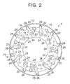
- FIG. 2 illustrates a detailed structure of the variable nozzle unit 7.
- the variable nozzle unit 7 is configured such that a plurality of variable nozzles 11 is assembled to a ring-shaped main plate 10 at regular intervals in a circumferential direction of the main plate 10.
- the variable nozzles 11 each include a nozzle pin 23, a nozzle vane 24 (illustrated in a broken line), and an arm 25.
- the nozzle pin 23 penetrates through the main plate 10 in a thickness direction thereof (a direction perpendicular to a plane of paper).
- the nozzle vane 24 is fixed to one end of the nozzle pin 23.
- the arm 25 is fixed to the other end of the nozzle pin 23.
- a plate-shaped unison ring 12 placed on the same axis as a center line of the main plate 10 and aligned with the main plate 10 in the thickness direction is assembled to the variable nozzle unit 7.
- the unison ring 12 is displaceable relative to the main plate 10 around the axis (in a circumferential direction).
- On an inner peripheral surface of the unison ring 12 a plurality of accommodation portions 26 into which respective ends of the arms 25 of the variable nozzles 11 are inserted is placed at regular intervals along the circumferential direction.
- a notch portion 16 into which an engagement pin 18 for engaging the actuator 9 (see FIG. 1 ) with the unison ring 12 is inserted is also formed on the inner peripheral surface of the unison ring 12.
- the unison ring 12 When a driving force of the actuator 9 is applied to the unison ring 12 via the engagement pin 18, the unison ring 12 is rotated (displaced in the circumferential direction). As a result, the arms 25 of the variable nozzles 11 are pushed by the unison ring 12 so as to pivot the nozzle pins 23 around their axes, and along with the pivoting of the nozzle pins 23, the nozzle vanes 24 pivot around the nozzle pins 23 at the same time and in the same direction.
- the nozzle vanes 24 (the variable nozzles 11) perform an opening-closing operation based on such pivoting of the nozzle vanes 24.
- a size of a gap between adjacent nozzle vanes 24, that is, the exhaust-gas flow area of the exhaust passage 8 ( FIG. 1 ) for blowing exhaust gas to the turbine wheel 6 is changed. Due to the change of the exhaust-gas flow area of the exhaust passage 8, the flow speed of the exhaust gas to be blown to the turbine wheel 6 is variable.
- a notch portion 17 into which a stopper 19 fixed to the main plate 10 is inserted is also formed on the inner peripheral surface of the unison ring 12 illustrated in FIG. 2 . Due to the notch portion 17 and the stopper 19, the circumferential displacement of the unison ring 12 is regulated within a predetermined range.
- FIG. 3 illustrates an attachment state of the variable nozzle unit 7 on the exhaust passage 8 of the turbocharger 4.
- the nozzle vanes 24 of the variable nozzles 11 are sandwiched between the main plate 10 of the variable nozzle unit 7 and a side plate 27 aligned therewith in the thickness direction of the main plate 10 (a right-left direction in the view).
- a distance between the main plate 10 and the side plate 27 is maintained, by a plurality of spacer pins 30 (only one spacer pin 30 is illustrated in FIG. 3 ) fixed therebetween, to a distance where the nozzle vanes 24 can be provided between the main plate 10 and the side plate 27.
- the unison ring 12 of the variable nozzle unit 7 is placed on that side of the main plate 10 which is opposite to the side plate 27.
- variable nozzle unit 7 Since the variable nozzle unit 7 is provided on the exhaust passage 8 of the turbocharger 4, the unison ring 12 and the main plate 10 are exposed to the exhaust gas. Because of this, foreign substances such as soot included in the exhaust gas may be accumulated between the unison ring 12 and the main plate 10, which may result in that the foreign substances disturb an appropriate operation of the variable nozzles 11.
- the following describes a structure to deal with such a problem, more specifically.
- a gap is formed between that first facing surface F1 of the unison ring 12 which is opposed to the main plate 10 and that second facing surface F2 of the main plate 10 which is opposed to the unison ring 12. That is, the facing surface F1 of the unison ring 12 is opposed to the facing surface F2 of main plate 10 via the gap.
- the gap makes it difficult for the foreign substances to be accumulated between the facing surfaces F1, F2. That is, since a relatively large gap can be secured between the main plate 10 and the unison ring 12, even if foreign substances enter into the gap, the foreign substances are hard to be accumulated therein.
- projections 41 that project from one surface F1 out of the facing surfaces F1, F2, toward the other surface F2 out of the facing surfaces F1, F2 are provided in the gap. More specifically, a plurality of recessed portions 42 is formed on that surface F1 which is one of the facing surfaces F1, F2 and is provided closer to the unison ring 12, at given intervals in the circumferential direction of the unison ring 12. The projections 41 are provided between the plurality of recessed portions 42 on the surface F1.
- the number and position of the projections 41 are set such that the projections 41 are displaced over the whole circumferential direction in the gap between the facing surfaces F1, F2 of the unison ring 12 and the main plate 10, through the displacement of the unison ring 12 over a whole displacement range in the circumferential direction to operate the variable nozzles 11 (see FIG. 2 ).
- the accommodation portions 26 into which the respective ends of the arms 25 of the variable nozzles 11 are inserted are formed in positions corresponding to the projections 41 thus set.
- variable nozzle turbocharger 4 when the unison ring 12 is displaced in the circumferential direction to operate the variable nozzles 11, the foreign substances such as soot attached to the gap between the facing surfaces F1, F2 of the unison ring 12 and the main plate 10 are scraped out from the gap by the projections 41 that project from the one surface F1 out of the facing surfaces F1, F2 toward the other surface F2 out of the facing surfaces F1, F2. That is, when the projections 41 are displaced in the circumferential direction integrally with the unison ring 12, the foreign substances attached to the gap between the facing surfaces F1, F2 are pushed by the projections 41, such that the foreign substances are discharged (scraped) out of the gap.
- the turbocharger 4 when the unison ring 12 is displaced in the circumferential direction to operate the variable nozzles 11, the foreign substances such as soot attached to the gap between the facing surfaces F1, F2 of the unison ring 12 and the main plate 10 are scraped out from the gap by the projections 41 that project from the one surface F1 out of the facing surfaces F1, F2 toward the other surface F2 out of the facing surfaces F1, F2. Accordingly, it is possible to restrain accumulation of the foreign substances between the unison ring 12 and the main plate 10, thereby making it possible to restrain such a problem that an appropriate operation of the variable nozzles 11 is disturbed by the foreign substances.
- the projections 41 are provided between the plurality of recessed portions 42 formed on the one surface F1 out of the facing surfaces F1, F2 of the unison ring 12 and the main plate 10, at given intervals in the circumferential direction of the unison ring 12. In view of this, when the unison ring 12 is displaced in the circumferential direction, the foreign substances attached to the gap between the facing surfaces F1, F2 can be effectively scraped out from the gap by the plurality of projections 41 provided between the facing surfaces F1, F2.
- the number and position of the projections 41 are set such that the projections 41 are displaced over the whole circumferential direction in the gap between the facing surfaces F1, F2 of the unison ring 12 and the main plate 10, through the displacement of the unison ring 12 over the whole displacement range in the circumferential direction to operate the variable nozzles 11. Accordingly, when the unison ring 12 is displaced over the whole displacement range in the circumferential direction, the foreign substances attached to the gap between the facing surfaces F1, F2 can be more surely scraped out from the gap by the projections 41.
- the above embodiment can be modified as follows, for example.
- the number and position of the projections 41 are set such that the projections 41 are displaced over the whole circumferential direction in the gap between the facing surfaces F1, F2 of the unison ring 12 and the main plate 10, through the displacement of the unison ring 12 over the whole displacement range in the circumferential direction.
- the number and position of the projections 41 may not necessarily be set in this way.
- the one surface F1 out of the facing surfaces F1, F2 may be set on the main plate 10, and the other surface F2 out of the facing surfaces F1, F2 may be set on the unison ring 12. In this case, the projections 41 project from the surface F1 of the main plate 10 toward the surface F2 of the unison ring 12.
- the recessed portions 42 are formed on the one surface F1 out of the facing surfaces F1, F2 of the unison ring 12 and the main plate 10, but also a plurality of recessed portions 43 may be formed on the other surface F2 at given intervals in the circumferential direction of the unison ring 12, such that the recessed portions 43 are opposed to the recessed portions 42.
- the distance between the facing surfaces F1, F2 of the unison ring 12 and the main plate 10 is increased due to the recessed portions 42, 43 opposed to each other as such, such that the gap between the facing surfaces F1, F2 can be widened, thereby resulting in that the foreign substances are hard to be accumulated in the gap.
- the plurality of recessed portions 43 is formed on the other surface F2 out of the facing surfaces F1, F2 of the unison ring 12 and the main plate 10, and projections 44 are provided between the recessed portions 43. Then, the projections 41 formed on the one surface F1 may be inserted into the recessed portions 43 formed on the other surface F2, and the projections 44 formed on the other surface F2 may be inserted into the recessed portions 42 formed on the one surface F1.
- the foreign substances attached to the gap between the facing surface F1, F2 of the unison ring 12 and the main plate 10 can be scraped out from the gap by the projections 41 formed on the one surface F1 and the projections 44 formed on the other surface F2, along with the circumferential displacement of the unison ring 12.
Landscapes
- Engineering & Computer Science (AREA)
- Mechanical Engineering (AREA)
- General Engineering & Computer Science (AREA)
- Supercharger (AREA)
Abstract
Description
- The present invention relates to a variable nozzle turbocharger.
- Japanese Patent Application Publication No.
2010-180864 JP 2010-180864 A - In the variable nozzle turbocharger, the unison ring and the main plate are exposed to the exhaust gas. Because of this, foreign substances such as soot included in the exhaust gas may be accumulated between the unison ring and the main plate. The foreign substances thus accumulated disturb the circumferential displacement of the unison ring, thereby resulting in that an appropriate operation of the variable nozzle may be disturbed by the foreign substances.
- The present invention provides a variable nozzle turbocharger that is able to restrain that an appropriate operation of a variable nozzle is disturbed by foreign substances accumulated between a unison ring and a main plate.
- A variable nozzle turbocharger according to a first aspect of the present invention is a variable nozzle turbocharger for changing a flow speed of exhaust gas to be blown to a turbine wheel and characterized by including a main plate, a unison ring, and variable nozzles. The unison ring is aligned with the main plate in a thickness direction of the main plate. The variable nozzles are configured such that their opening degrees are changed along with rotation of the unison ring. A first facing surface of the unison ring is opposed to a second facing surface of the main plate via a gap, and the first facing surface is provided with a plurality of first projections projecting toward the second facing surface and placed at intervals along a circumferential direction of the unison ring. According to the above configuration, when the unison ring is rotated (displaced in the circumferential direction) so as to operate the variable nozzles, foreign substances such as soot attached to the gap between the first facing surface and the second facing surface of the unison ring and the main plate are discharged from the gap. More specifically, when the unison ring is displaced in the circumferential direction, the foreign substances attached to the gap is scraped out from the gap by the plurality of first projections projecting from the first facing surface toward the second facing surface. This accordingly makes it possible to restrain such a problem that an appropriate operation of the variable nozzles is disturbed by the foreign substances accumulated between the unison ring and the main plate.
- In the variable nozzle turbocharger, the first facing surface may include a plurality of first recessed portions placed at intervals in the circumferential direction of the unison ring, and the plurality of first projections and the plurality of first recessed portions may be alternately arranged on the first facing surface along with the circumferential direction of the unison ring. According to the above configuration, the foreign substances attached to the gap can be effectively scraped out from the gap by the plurality of first projections provided between the first facing surface and the second facing surface.
- In the variable nozzle turbocharger, the second facing surface may include a plurality of second recessed portions placed at intervals in the circumferential direction of the unison ring, and the plurality of second recessed portions may be opposed to the plurality of first recessed portions provided on the first facing surface. According to the above configuration, a distance between the facing surfaces F1, F2 of the unison ring and the main plate is increased due to the recessed portions thus opposed to each other, such that the gap between the facing surfaces F1, F2 can be widened, thereby resulting in that the foreign substances are hard to be accumulated in the gap.
- In the variable nozzle turbocharger, the second facing surface may include a plurality of second recessed portions placed at intervals in the circumferential direction of the unison ring, and may include a plurality of second projections placed at intervals in the circumferential direction of the unison ring, the plurality of second projections and the plurality of second recessed portions may be alternately arranged on the second facing surface along with the circumferential direction of the unison ring, the plurality of first projections provided on the first facing surface may be inserted into the plurality of second recessed portions, and the plurality of second projections may be inserted into the plurality of first recessed portions. According to the above configuration, the foreign substances attached to the gap between the first facing surface and the second facing surface of the unison ring and the main plate can be scraped out from the gap by the first projections provided on the first facing surface and the second projections provided on the second facing surface, along with the circumferential displacement of the unison ring.
- In the variable nozzle turbocharger, the number and position of the plurality of first projections may be set such that the first projections is displaced over the whole circumferential direction of the unison ring in the gap between the first facing surface and the second facing surface, through the circumferential displacement of the unison ring over a whole displacement range of the unison ring to operate the variable nozzles. According to the above configuration, when the unison ring is displaced in the circumferential direction over the whole displacement range to operate the variable nozzles, the foreign substances attached to the gap between the first facing surface and the second facing surface can be scraped out from the gap by the projections.
- In the variable nozzle turbocharger, the number and position of the plurality of first projections may be set such that the plurality of first projections and the plurality of second projections are displaced over the whole circumferential direction of the unison ring in the gap between the first facing surface and the second facing surface, through the circumferential displacement of the unison ring over the whole displacement range of the unison ring to operate the variable nozzles.
- Features, advantages, and technical and industrial significance of exemplary embodiments of the invention will be described below with reference to the accompanying drawings, in which like numerals denote like elements, and wherein:
-
FIG. 1 is a schematic drawing illustrating a variable nozzle turbocharger and an engine according to one embodiment of the present invention; -
FIG. 2 is a front view illustrating a variable nozzle unit of the turbocharger according to the above embodiment; -
FIG. 3 is an enlarged sectional view illustrating an attachment form of the variable nozzle unit according to the above embodiment; -
FIG. 4A is a side view illustrating a unison ring and a main plate according to the above embodiment; -
FIG. 4B is a perspective view illustrating the unison ring and the main plate according to the above embodiment; -
FIG. 5 is a side view illustrating another examples of the unison ring and the main plate according to the above embodiment; and -
FIG. 6 is a side view illustrating another example of the unison ring and the main plate according to the above embodiment. - One embodiment of a variable nozzle turbocharger is described below with reference to
FIGS. 1 to 4 . As illustrated inFIG. 1 , an upstream portion of anintake path 2 and a downstream portion of an exhaust pipe 3 in an engine 1 are connected to avariable nozzle turbocharger 4. Theturbocharger 4 includes acompressor wheel 5 and aturbine wheel 6. Thecompressor wheel 5 sends air to a downstream side of theintake path 2. Theturbine wheel 6 is rotated based on blowing of exhaust gas passing through the exhaust pipe 3. When theturbine wheel 6 is rotated, thecompressor wheel 5 is rotated integrally with theturbine wheel 6, thereby increasing an air intake amount of the engine 1 and improving an output of the engine 1. - In the
turbocharger 4, avariable nozzle unit 7 is attached onto anexhaust passage 8 for blowing exhaust gas to theturbine wheel 6. Thevariable nozzle unit 7 is driven by an actuator 9 so as to increase and decrease an exhaust-gas flow area of theexhaust passage 8. Hereby, a flow speed of the exhaust gas to be blown to theturbine wheel 6 is variable. Since the flow speed of the exhaust gas to be blown to theturbine wheel 6 is variable as such, a rotation speed of theturbocharger 4 is changed, such that a boost pressure (intake pressure) of the engine 1 is adjusted. More specifically, when the exhaust-gas flow area of theexhaust passage 8 is decreased, the flow speed of the exhaust gas to be blown to theturbine wheel 6 becomes faster and the rotation speed of theturbocharger 4 is increased, thereby increasing the boost pressure of the engine 1. In the meantime, when the exhaust-gas flow area of theexhaust passage 8 is increased, the flow speed of the exhaust gas to be blown to theturbine wheel 6 becomes slower and the rotation speed of theturbocharger 4 is decreased, thereby decreasing the boost pressure of the engine 1. -
FIG. 2 illustrates a detailed structure of thevariable nozzle unit 7. As illustrated in the figure, thevariable nozzle unit 7 is configured such that a plurality ofvariable nozzles 11 is assembled to a ring-shapedmain plate 10 at regular intervals in a circumferential direction of themain plate 10. Thevariable nozzles 11 each include anozzle pin 23, a nozzle vane 24 (illustrated in a broken line), and anarm 25. Thenozzle pin 23 penetrates through themain plate 10 in a thickness direction thereof (a direction perpendicular to a plane of paper). Thenozzle vane 24 is fixed to one end of thenozzle pin 23. Thearm 25 is fixed to the other end of thenozzle pin 23. A plate-shaped unison ring 12 placed on the same axis as a center line of themain plate 10 and aligned with themain plate 10 in the thickness direction is assembled to thevariable nozzle unit 7. Theunison ring 12 is displaceable relative to themain plate 10 around the axis (in a circumferential direction). On an inner peripheral surface of theunison ring 12, a plurality ofaccommodation portions 26 into which respective ends of thearms 25 of thevariable nozzles 11 are inserted is placed at regular intervals along the circumferential direction. Further, anotch portion 16 into which anengagement pin 18 for engaging the actuator 9 (seeFIG. 1 ) with theunison ring 12 is inserted is also formed on the inner peripheral surface of theunison ring 12. - When a driving force of the actuator 9 is applied to the
unison ring 12 via theengagement pin 18, theunison ring 12 is rotated (displaced in the circumferential direction). As a result, thearms 25 of thevariable nozzles 11 are pushed by theunison ring 12 so as to pivot thenozzle pins 23 around their axes, and along with the pivoting of thenozzle pins 23, the nozzle vanes 24 pivot around thenozzle pins 23 at the same time and in the same direction. The nozzle vanes 24 (the variable nozzles 11) perform an opening-closing operation based on such pivoting of thenozzle vanes 24. Based on the opening-closing operation (an opening-degree change operation), a size of a gap betweenadjacent nozzle vanes 24, that is, the exhaust-gas flow area of the exhaust passage 8 (FIG. 1 ) for blowing exhaust gas to theturbine wheel 6 is changed. Due to the change of the exhaust-gas flow area of theexhaust passage 8, the flow speed of the exhaust gas to be blown to theturbine wheel 6 is variable. Anotch portion 17 into which astopper 19 fixed to themain plate 10 is inserted is also formed on the inner peripheral surface of theunison ring 12 illustrated inFIG. 2 . Due to thenotch portion 17 and thestopper 19, the circumferential displacement of theunison ring 12 is regulated within a predetermined range. -
FIG. 3 illustrates an attachment state of thevariable nozzle unit 7 on theexhaust passage 8 of theturbocharger 4. As can be seen from the figure, thenozzle vanes 24 of thevariable nozzles 11 are sandwiched between themain plate 10 of thevariable nozzle unit 7 and aside plate 27 aligned therewith in the thickness direction of the main plate 10 (a right-left direction in the view). Note that a distance between themain plate 10 and theside plate 27 is maintained, by a plurality of spacer pins 30 (only onespacer pin 30 is illustrated inFIG. 3 ) fixed therebetween, to a distance where thenozzle vanes 24 can be provided between themain plate 10 and theside plate 27. Theunison ring 12 of thevariable nozzle unit 7 is placed on that side of themain plate 10 which is opposite to theside plate 27. - Since the
variable nozzle unit 7 is provided on theexhaust passage 8 of theturbocharger 4, theunison ring 12 and themain plate 10 are exposed to the exhaust gas. Because of this, foreign substances such as soot included in the exhaust gas may be accumulated between theunison ring 12 and themain plate 10, which may result in that the foreign substances disturb an appropriate operation of thevariable nozzles 11. The following describes a structure to deal with such a problem, more specifically. - As illustrated in
FIGS. 4A and 4B , a gap is formed between that first facing surface F1 of theunison ring 12 which is opposed to themain plate 10 and that second facing surface F2 of themain plate 10 which is opposed to theunison ring 12. That is, the facing surface F1 of theunison ring 12 is opposed to the facing surface F2 ofmain plate 10 via the gap. The gap makes it difficult for the foreign substances to be accumulated between the facing surfaces F1, F2. That is, since a relatively large gap can be secured between themain plate 10 and theunison ring 12, even if foreign substances enter into the gap, the foreign substances are hard to be accumulated therein. Further,projections 41 that project from one surface F1 out of the facing surfaces F1, F2, toward the other surface F2 out of the facing surfaces F1, F2 are provided in the gap. More specifically, a plurality of recessedportions 42 is formed on that surface F1 which is one of the facing surfaces F1, F2 and is provided closer to theunison ring 12, at given intervals in the circumferential direction of theunison ring 12. Theprojections 41 are provided between the plurality of recessedportions 42 on the surface F1. - The number and position of the
projections 41 are set such that theprojections 41 are displaced over the whole circumferential direction in the gap between the facing surfaces F1, F2 of theunison ring 12 and themain plate 10, through the displacement of theunison ring 12 over a whole displacement range in the circumferential direction to operate the variable nozzles 11 (seeFIG. 2 ). In theunison ring 12, theaccommodation portions 26 into which the respective ends of thearms 25 of thevariable nozzles 11 are inserted are formed in positions corresponding to theprojections 41 thus set. - The following describes an operation of the
variable nozzle turbocharger 4. In theturbocharger 4, when theunison ring 12 is displaced in the circumferential direction to operate thevariable nozzles 11, the foreign substances such as soot attached to the gap between the facing surfaces F1, F2 of theunison ring 12 and themain plate 10 are scraped out from the gap by theprojections 41 that project from the one surface F1 out of the facing surfaces F1, F2 toward the other surface F2 out of the facing surfaces F1, F2. That is, when theprojections 41 are displaced in the circumferential direction integrally with theunison ring 12, the foreign substances attached to the gap between the facing surfaces F1, F2 are pushed by theprojections 41, such that the foreign substances are discharged (scraped) out of the gap. Accordingly, accumulation of the foreign substances between theunison ring 12 and themain plate 10 is restrained. As a result, it is possible to restrain such a problem that the foreign substances disturb the circumferential displacement of theunison ring 12 or the pivoting of nozzle pins 23 around their axes, that is, it is possible to restrain such a problem that an appropriate opening-closing operation of thevariable nozzles 11 is disturbed by the foreign substances. - According to the above embodiment described above, it is possible to obtain the following effects. In the
turbocharger 4, when theunison ring 12 is displaced in the circumferential direction to operate thevariable nozzles 11, the foreign substances such as soot attached to the gap between the facing surfaces F1, F2 of theunison ring 12 and themain plate 10 are scraped out from the gap by theprojections 41 that project from the one surface F1 out of the facing surfaces F1, F2 toward the other surface F2 out of the facing surfaces F1, F2. Accordingly, it is possible to restrain accumulation of the foreign substances between theunison ring 12 and themain plate 10, thereby making it possible to restrain such a problem that an appropriate operation of thevariable nozzles 11 is disturbed by the foreign substances. - The
projections 41 are provided between the plurality of recessedportions 42 formed on the one surface F1 out of the facing surfaces F1, F2 of theunison ring 12 and themain plate 10, at given intervals in the circumferential direction of theunison ring 12. In view of this, when theunison ring 12 is displaced in the circumferential direction, the foreign substances attached to the gap between the facing surfaces F1, F2 can be effectively scraped out from the gap by the plurality ofprojections 41 provided between the facing surfaces F1, F2. - The number and position of the
projections 41 are set such that theprojections 41 are displaced over the whole circumferential direction in the gap between the facing surfaces F1, F2 of theunison ring 12 and themain plate 10, through the displacement of theunison ring 12 over the whole displacement range in the circumferential direction to operate thevariable nozzles 11. Accordingly, when theunison ring 12 is displaced over the whole displacement range in the circumferential direction, the foreign substances attached to the gap between the facing surfaces F1, F2 can be more surely scraped out from the gap by theprojections 41. - The above embodiment can be modified as follows, for example. The number and position of the
projections 41 are set such that theprojections 41 are displaced over the whole circumferential direction in the gap between the facing surfaces F1, F2 of theunison ring 12 and themain plate 10, through the displacement of theunison ring 12 over the whole displacement range in the circumferential direction. However, the number and position of theprojections 41 may not necessarily be set in this way. - It is not necessary to provide the plurality of
projections 41. The one surface F1 out of the facing surfaces F1, F2 may be set on themain plate 10, and the other surface F2 out of the facing surfaces F1, F2 may be set on theunison ring 12. In this case, theprojections 41 project from the surface F1 of themain plate 10 toward the surface F2 of theunison ring 12. - As illustrated in
FIG. 5 , not only the recessedportions 42 are formed on the one surface F1 out of the facing surfaces F1, F2 of theunison ring 12 and themain plate 10, but also a plurality of recessedportions 43 may be formed on the other surface F2 at given intervals in the circumferential direction of theunison ring 12, such that the recessedportions 43 are opposed to the recessedportions 42. In this case, the distance between the facing surfaces F1, F2 of theunison ring 12 and themain plate 10 is increased due to the recessedportions - As illustrated in
FIG. 6 , the plurality of recessedportions 43 is formed on the other surface F2 out of the facing surfaces F1, F2 of theunison ring 12 and themain plate 10, andprojections 44 are provided between the recessedportions 43. Then, theprojections 41 formed on the one surface F1 may be inserted into the recessedportions 43 formed on the other surface F2, and theprojections 44 formed on the other surface F2 may be inserted into the recessedportions 42 formed on the one surface F1. In this case, the foreign substances attached to the gap between the facing surface F1, F2 of theunison ring 12 and themain plate 10 can be scraped out from the gap by theprojections 41 formed on the one surface F1 and theprojections 44 formed on the other surface F2, along with the circumferential displacement of theunison ring 12.
Claims (6)
- A variable nozzle turbocharger for changing a flow speed of exhaust gas to be blown to a turbine wheel (6), the variable nozzle turbocharger characterized by comprising:a main plate (10);a unison ring (12) aligned with the main plate in a thickness direction of the main plate; andvariable nozzles (11) configured such that their opening degrees are changed along with rotation of the unison ring, wherein:a first facing surface (F1) of the unison ring is opposed to a second facing surface (F2) of the main plate via a gap; andthe first facing surface is provided with a plurality of first projections (41) projecting toward the second facing surface and placed at intervals along a circumferential direction of the unison ring.
- The variable nozzle turbocharger according to claim 1, wherein
the first facing surface includes a plurality of first recessed portions (42) placed at intervals in the circumferential direction of the unison ring, and
the plurality of first projections and the plurality of first recessed portions are alternately arranged on the first facing surface along with the circumferential direction of the unison ring. - The variable nozzle turbocharger according to claim 2, wherein
the second facing surface includes a plurality of second recessed portions (43) placed at intervals in the circumferential direction of the unison ring, and
the plurality of second recessed portions is opposed to the plurality of first recessed portions provided on the first facing surface. - The variable nozzle turbocharger according to claim 2, wherein:the second facing surface includes a plurality of second recessed portions (43) placed at intervals in the circumferential direction of the unison ring, and includes a plurality of second projections (44) placed at intervals in the circumferential direction of the unison ring;the plurality of second projections and the plurality of second recessed portions are alternately arranged on the second facing surface along with the circumferential direction of the unison ring;the plurality of first projections provided on the first facing surface is inserted into the plurality of second recessed portions; andthe plurality of second projections is inserted into the plurality of first recessed portions.
- The variable nozzle turbocharger according to claim 2 or 3, wherein:the number and position of the plurality of first projections are set such that the plurality of first projections is displaced over the whole circumferential direction of the unison ring in the gap between the first facing surface and the second facing surface, through the circumferential displacement of the unison ring over a whole displacement range of the unison ring to operate the variable nozzles.
- The variable nozzle turbocharger according to claim 4, wherein:the number and position of the plurality of first projections are set such that the plurality of first projections and the plurality of second projections are displaced over the whole circumferential direction of the unison ring in the gap between the first facing surface and the second facing surface, through the circumferential displacement of the unison ring over a whole displacement range of the unison ring to operate the variable nozzles.
Applications Claiming Priority (1)
| Application Number | Priority Date | Filing Date | Title |
|---|---|---|---|
| JP2013233360A JP5924329B2 (en) | 2013-11-11 | 2013-11-11 | Variable nozzle turbocharger |
Publications (2)
| Publication Number | Publication Date |
|---|---|
| EP2871328A1 true EP2871328A1 (en) | 2015-05-13 |
| EP2871328B1 EP2871328B1 (en) | 2021-05-26 |
Family
ID=51868862
Family Applications (1)
| Application Number | Title | Priority Date | Filing Date |
|---|---|---|---|
| EP14192318.5A Active EP2871328B1 (en) | 2013-11-11 | 2014-11-07 | Variable nozzle turbocharger with means to reduce accumulation of soot |
Country Status (2)
| Country | Link |
|---|---|
| EP (1) | EP2871328B1 (en) |
| JP (1) | JP5924329B2 (en) |
Cited By (2)
| Publication number | Priority date | Publication date | Assignee | Title |
|---|---|---|---|---|
| CN106065878A (en) * | 2015-04-21 | 2016-11-02 | 曼柴油机和涡轮机欧洲股份公司 | Fluid machine |
| US10851706B2 (en) | 2015-02-24 | 2020-12-01 | Mitsubishi Heavy Industries Engine & Turbocharger, Ltd. | Variable nozzle mechanism and variable displacement type exhaust turbocharger |
Families Citing this family (1)
| Publication number | Priority date | Publication date | Assignee | Title |
|---|---|---|---|---|
| WO2026004448A1 (en) * | 2024-06-26 | 2026-01-02 | 株式会社Ihi | Variable capacity mechanism and supercharger |
Citations (5)
| Publication number | Priority date | Publication date | Assignee | Title |
|---|---|---|---|---|
| US20020098081A1 (en) * | 2001-01-24 | 2002-07-25 | Mahle Gmbh-Patent Dept. | Guide blade adjusting device for a turbocharger |
| JP2010180864A (en) | 2009-02-09 | 2010-08-19 | Toyota Motor Corp | Variable nozzle unit |
| US20100215482A1 (en) * | 2009-02-11 | 2010-08-26 | Andreas Prang | Adjusting ring for a charging device, more preferably for an exhaust gas turbocharger of a motor vehicle |
| US20110182717A1 (en) * | 2006-03-30 | 2011-07-28 | Borgwarner Inc. | Turbocharger |
| JP2012140894A (en) * | 2010-12-28 | 2012-07-26 | Toyota Motor Corp | Method for manufacturing drive ring, drive ring, and variable nozzle mechanism using the drive ring |
Family Cites Families (6)
| Publication number | Priority date | Publication date | Assignee | Title |
|---|---|---|---|---|
| JPH0350242Y2 (en) * | 1985-12-25 | 1991-10-28 | ||
| JPH1037754A (en) * | 1996-07-24 | 1998-02-10 | Toyota Motor Corp | Variable nozzle turbocharger |
| JP2006132444A (en) * | 2004-11-05 | 2006-05-25 | Toyota Motor Corp | Turbocharger variable turbocharger |
| JP2009257090A (en) * | 2008-04-11 | 2009-11-05 | Toyota Motor Corp | Variable capacity turbocharger |
| JP5071421B2 (en) * | 2009-03-24 | 2012-11-14 | トヨタ自動車株式会社 | Variable nozzle turbocharger |
| US9017017B2 (en) * | 2009-04-10 | 2015-04-28 | Honeywell Internatonal Inc. | Variable-vane assembly having fixed guide pins for unison ring |
-
2013
- 2013-11-11 JP JP2013233360A patent/JP5924329B2/en not_active Expired - Fee Related
-
2014
- 2014-11-07 EP EP14192318.5A patent/EP2871328B1/en active Active
Patent Citations (5)
| Publication number | Priority date | Publication date | Assignee | Title |
|---|---|---|---|---|
| US20020098081A1 (en) * | 2001-01-24 | 2002-07-25 | Mahle Gmbh-Patent Dept. | Guide blade adjusting device for a turbocharger |
| US20110182717A1 (en) * | 2006-03-30 | 2011-07-28 | Borgwarner Inc. | Turbocharger |
| JP2010180864A (en) | 2009-02-09 | 2010-08-19 | Toyota Motor Corp | Variable nozzle unit |
| US20100215482A1 (en) * | 2009-02-11 | 2010-08-26 | Andreas Prang | Adjusting ring for a charging device, more preferably for an exhaust gas turbocharger of a motor vehicle |
| JP2012140894A (en) * | 2010-12-28 | 2012-07-26 | Toyota Motor Corp | Method for manufacturing drive ring, drive ring, and variable nozzle mechanism using the drive ring |
Cited By (2)
| Publication number | Priority date | Publication date | Assignee | Title |
|---|---|---|---|---|
| US10851706B2 (en) | 2015-02-24 | 2020-12-01 | Mitsubishi Heavy Industries Engine & Turbocharger, Ltd. | Variable nozzle mechanism and variable displacement type exhaust turbocharger |
| CN106065878A (en) * | 2015-04-21 | 2016-11-02 | 曼柴油机和涡轮机欧洲股份公司 | Fluid machine |
Also Published As
| Publication number | Publication date |
|---|---|
| JP2015094266A (en) | 2015-05-18 |
| EP2871328B1 (en) | 2021-05-26 |
| JP5924329B2 (en) | 2016-05-25 |
Similar Documents
| Publication | Publication Date | Title |
|---|---|---|
| EP2821652B1 (en) | Centrifugal fluid machine with air intake pipe structure | |
| US9249736B2 (en) | Inlet guide vanes and gas turbine engine systems involving such vanes | |
| US20170292381A1 (en) | Exhaust turbine for turbocharger | |
| US10563515B2 (en) | Turbine impeller and variable geometry turbine | |
| EP2339126A1 (en) | Variable capacity turbine | |
| EP2871328B1 (en) | Variable nozzle turbocharger with means to reduce accumulation of soot | |
| US8061983B1 (en) | Exhaust diffuser strut with stepped trailing edge | |
| WO2016035329A1 (en) | Exhaust turbine for turbocharger | |
| US11215057B2 (en) | Turbine wheel, turbine, and turbocharger | |
| CN104204445B (en) | Blade dial bundle LMS for VTG turbocharger | |
| EP3267009B1 (en) | Waste gate valve and turbocharger | |
| US10472983B2 (en) | On-off valve device and rotary machine | |
| JP4933082B2 (en) | Butterfly valve | |
| CN108884721A (en) | Turbocharger with compressor with variable deburring | |
| KR20160100823A (en) | Vane ring thermal strain relief cuts | |
| EP3221564B1 (en) | Turbomachine including a vane and method of assembling such turbomachine | |
| JP2008151033A (en) | Jet flow exhaust nozzle and jet engine | |
| CN102597454A (en) | Turbocharger | |
| CA3038499A1 (en) | Gas path duct for a gas turbine engine | |
| JP5402548B2 (en) | Variable capacity turbocharger | |
| JP2013535615A (en) | Exhaust gas turbocharger | |
| EP3205872A1 (en) | Intake noise reduction device | |
| CN110582648B (en) | Centrifugal compressor and turbocharger having the same | |
| JPH11257082A (en) | Nozzle vane shape for variable capacity turbocharger | |
| JP2016053353A (en) | Turbocharger exhaust turbine |
Legal Events
| Date | Code | Title | Description |
|---|---|---|---|
| PUAI | Public reference made under article 153(3) epc to a published international application that has entered the european phase |
Free format text: ORIGINAL CODE: 0009012 |
|
| 17P | Request for examination filed |
Effective date: 20141107 |
|
| AK | Designated contracting states |
Kind code of ref document: A1 Designated state(s): AL AT BE BG CH CY CZ DE DK EE ES FI FR GB GR HR HU IE IS IT LI LT LU LV MC MK MT NL NO PL PT RO RS SE SI SK SM TR |
|
| AX | Request for extension of the european patent |
Extension state: BA ME |
|
| STAA | Information on the status of an ep patent application or granted ep patent |
Free format text: STATUS: EXAMINATION IS IN PROGRESS |
|
| 17Q | First examination report despatched |
Effective date: 20170223 |
|
| GRAP | Despatch of communication of intention to grant a patent |
Free format text: ORIGINAL CODE: EPIDOSNIGR1 |
|
| STAA | Information on the status of an ep patent application or granted ep patent |
Free format text: STATUS: GRANT OF PATENT IS INTENDED |
|
| INTG | Intention to grant announced |
Effective date: 20210114 |
|
| GRAS | Grant fee paid |
Free format text: ORIGINAL CODE: EPIDOSNIGR3 |
|
| GRAA | (expected) grant |
Free format text: ORIGINAL CODE: 0009210 |
|
| STAA | Information on the status of an ep patent application or granted ep patent |
Free format text: STATUS: THE PATENT HAS BEEN GRANTED |
|
| AK | Designated contracting states |
Kind code of ref document: B1 Designated state(s): AL AT BE BG CH CY CZ DE DK EE ES FI FR GB GR HR HU IE IS IT LI LT LU LV MC MK MT NL NO PL PT RO RS SE SI SK SM TR |
|
| RAP3 | Party data changed (applicant data changed or rights of an application transferred) |
Owner name: TOYOTA JIDOSHA KABUSHIKI KAISHA |
|
| REG | Reference to a national code |
Ref country code: GB Ref legal event code: FG4D |
|
| REG | Reference to a national code |
Ref country code: CH Ref legal event code: EP |
|
| REG | Reference to a national code |
Ref country code: DE Ref legal event code: R096 Ref document number: 602014077678 Country of ref document: DE |
|
| REG | Reference to a national code |
Ref country code: AT Ref legal event code: REF Ref document number: 1396414 Country of ref document: AT Kind code of ref document: T Effective date: 20210615 |
|
| REG | Reference to a national code |
Ref country code: IE Ref legal event code: FG4D |
|
| REG | Reference to a national code |
Ref country code: LT Ref legal event code: MG9D |
|
| REG | Reference to a national code |
Ref country code: AT Ref legal event code: MK05 Ref document number: 1396414 Country of ref document: AT Kind code of ref document: T Effective date: 20210526 |
|
| PG25 | Lapsed in a contracting state [announced via postgrant information from national office to epo] |
Ref country code: BG Free format text: LAPSE BECAUSE OF FAILURE TO SUBMIT A TRANSLATION OF THE DESCRIPTION OR TO PAY THE FEE WITHIN THE PRESCRIBED TIME-LIMIT Effective date: 20210826 Ref country code: AT Free format text: LAPSE BECAUSE OF FAILURE TO SUBMIT A TRANSLATION OF THE DESCRIPTION OR TO PAY THE FEE WITHIN THE PRESCRIBED TIME-LIMIT Effective date: 20210526 Ref country code: LT Free format text: LAPSE BECAUSE OF FAILURE TO SUBMIT A TRANSLATION OF THE DESCRIPTION OR TO PAY THE FEE WITHIN THE PRESCRIBED TIME-LIMIT Effective date: 20210526 Ref country code: FI Free format text: LAPSE BECAUSE OF FAILURE TO SUBMIT A TRANSLATION OF THE DESCRIPTION OR TO PAY THE FEE WITHIN THE PRESCRIBED TIME-LIMIT Effective date: 20210526 Ref country code: HR Free format text: LAPSE BECAUSE OF FAILURE TO SUBMIT A TRANSLATION OF THE DESCRIPTION OR TO PAY THE FEE WITHIN THE PRESCRIBED TIME-LIMIT Effective date: 20210526 |
|
| REG | Reference to a national code |
Ref country code: NL Ref legal event code: MP Effective date: 20210526 |
|
| PG25 | Lapsed in a contracting state [announced via postgrant information from national office to epo] |
Ref country code: LV Free format text: LAPSE BECAUSE OF FAILURE TO SUBMIT A TRANSLATION OF THE DESCRIPTION OR TO PAY THE FEE WITHIN THE PRESCRIBED TIME-LIMIT Effective date: 20210526 Ref country code: GR Free format text: LAPSE BECAUSE OF FAILURE TO SUBMIT A TRANSLATION OF THE DESCRIPTION OR TO PAY THE FEE WITHIN THE PRESCRIBED TIME-LIMIT Effective date: 20210827 Ref country code: IS Free format text: LAPSE BECAUSE OF FAILURE TO SUBMIT A TRANSLATION OF THE DESCRIPTION OR TO PAY THE FEE WITHIN THE PRESCRIBED TIME-LIMIT Effective date: 20210926 Ref country code: RS Free format text: LAPSE BECAUSE OF FAILURE TO SUBMIT A TRANSLATION OF THE DESCRIPTION OR TO PAY THE FEE WITHIN THE PRESCRIBED TIME-LIMIT Effective date: 20210526 Ref country code: SE Free format text: LAPSE BECAUSE OF FAILURE TO SUBMIT A TRANSLATION OF THE DESCRIPTION OR TO PAY THE FEE WITHIN THE PRESCRIBED TIME-LIMIT Effective date: 20210526 Ref country code: NO Free format text: LAPSE BECAUSE OF FAILURE TO SUBMIT A TRANSLATION OF THE DESCRIPTION OR TO PAY THE FEE WITHIN THE PRESCRIBED TIME-LIMIT Effective date: 20210826 Ref country code: PT Free format text: LAPSE BECAUSE OF FAILURE TO SUBMIT A TRANSLATION OF THE DESCRIPTION OR TO PAY THE FEE WITHIN THE PRESCRIBED TIME-LIMIT Effective date: 20210927 Ref country code: PL Free format text: LAPSE BECAUSE OF FAILURE TO SUBMIT A TRANSLATION OF THE DESCRIPTION OR TO PAY THE FEE WITHIN THE PRESCRIBED TIME-LIMIT Effective date: 20210526 |
|
| PG25 | Lapsed in a contracting state [announced via postgrant information from national office to epo] |
Ref country code: NL Free format text: LAPSE BECAUSE OF FAILURE TO SUBMIT A TRANSLATION OF THE DESCRIPTION OR TO PAY THE FEE WITHIN THE PRESCRIBED TIME-LIMIT Effective date: 20210526 |
|
| PG25 | Lapsed in a contracting state [announced via postgrant information from national office to epo] |
Ref country code: RO Free format text: LAPSE BECAUSE OF FAILURE TO SUBMIT A TRANSLATION OF THE DESCRIPTION OR TO PAY THE FEE WITHIN THE PRESCRIBED TIME-LIMIT Effective date: 20210526 Ref country code: ES Free format text: LAPSE BECAUSE OF FAILURE TO SUBMIT A TRANSLATION OF THE DESCRIPTION OR TO PAY THE FEE WITHIN THE PRESCRIBED TIME-LIMIT Effective date: 20210526 Ref country code: SK Free format text: LAPSE BECAUSE OF FAILURE TO SUBMIT A TRANSLATION OF THE DESCRIPTION OR TO PAY THE FEE WITHIN THE PRESCRIBED TIME-LIMIT Effective date: 20210526 Ref country code: SM Free format text: LAPSE BECAUSE OF FAILURE TO SUBMIT A TRANSLATION OF THE DESCRIPTION OR TO PAY THE FEE WITHIN THE PRESCRIBED TIME-LIMIT Effective date: 20210526 Ref country code: DK Free format text: LAPSE BECAUSE OF FAILURE TO SUBMIT A TRANSLATION OF THE DESCRIPTION OR TO PAY THE FEE WITHIN THE PRESCRIBED TIME-LIMIT Effective date: 20210526 Ref country code: EE Free format text: LAPSE BECAUSE OF FAILURE TO SUBMIT A TRANSLATION OF THE DESCRIPTION OR TO PAY THE FEE WITHIN THE PRESCRIBED TIME-LIMIT Effective date: 20210526 Ref country code: CZ Free format text: LAPSE BECAUSE OF FAILURE TO SUBMIT A TRANSLATION OF THE DESCRIPTION OR TO PAY THE FEE WITHIN THE PRESCRIBED TIME-LIMIT Effective date: 20210526 |
|
| REG | Reference to a national code |
Ref country code: DE Ref legal event code: R097 Ref document number: 602014077678 Country of ref document: DE |
|
| PLBE | No opposition filed within time limit |
Free format text: ORIGINAL CODE: 0009261 |
|
| STAA | Information on the status of an ep patent application or granted ep patent |
Free format text: STATUS: NO OPPOSITION FILED WITHIN TIME LIMIT |
|
| 26N | No opposition filed |
Effective date: 20220301 |
|
| PG25 | Lapsed in a contracting state [announced via postgrant information from national office to epo] |
Ref country code: IS Free format text: LAPSE BECAUSE OF FAILURE TO SUBMIT A TRANSLATION OF THE DESCRIPTION OR TO PAY THE FEE WITHIN THE PRESCRIBED TIME-LIMIT Effective date: 20210926 Ref country code: AL Free format text: LAPSE BECAUSE OF FAILURE TO SUBMIT A TRANSLATION OF THE DESCRIPTION OR TO PAY THE FEE WITHIN THE PRESCRIBED TIME-LIMIT Effective date: 20210526 |
|
| PG25 | Lapsed in a contracting state [announced via postgrant information from national office to epo] |
Ref country code: MC Free format text: LAPSE BECAUSE OF FAILURE TO SUBMIT A TRANSLATION OF THE DESCRIPTION OR TO PAY THE FEE WITHIN THE PRESCRIBED TIME-LIMIT Effective date: 20210526 |
|
| REG | Reference to a national code |
Ref country code: CH Ref legal event code: PL |
|
| GBPC | Gb: european patent ceased through non-payment of renewal fee |
Effective date: 20211107 |
|
| PG25 | Lapsed in a contracting state [announced via postgrant information from national office to epo] |
Ref country code: LU Free format text: LAPSE BECAUSE OF NON-PAYMENT OF DUE FEES Effective date: 20211107 Ref country code: IT Free format text: LAPSE BECAUSE OF FAILURE TO SUBMIT A TRANSLATION OF THE DESCRIPTION OR TO PAY THE FEE WITHIN THE PRESCRIBED TIME-LIMIT Effective date: 20210526 Ref country code: BE Free format text: LAPSE BECAUSE OF NON-PAYMENT OF DUE FEES Effective date: 20211130 |
|
| REG | Reference to a national code |
Ref country code: BE Ref legal event code: MM Effective date: 20211130 |
|
| PG25 | Lapsed in a contracting state [announced via postgrant information from national office to epo] |
Ref country code: LI Free format text: LAPSE BECAUSE OF NON-PAYMENT OF DUE FEES Effective date: 20211130 Ref country code: CH Free format text: LAPSE BECAUSE OF NON-PAYMENT OF DUE FEES Effective date: 20211130 |
|
| PG25 | Lapsed in a contracting state [announced via postgrant information from national office to epo] |
Ref country code: IE Free format text: LAPSE BECAUSE OF NON-PAYMENT OF DUE FEES Effective date: 20211107 Ref country code: GB Free format text: LAPSE BECAUSE OF NON-PAYMENT OF DUE FEES Effective date: 20211107 |
|
| PG25 | Lapsed in a contracting state [announced via postgrant information from national office to epo] |
Ref country code: FR Free format text: LAPSE BECAUSE OF NON-PAYMENT OF DUE FEES Effective date: 20211130 |
|
| PGFP | Annual fee paid to national office [announced via postgrant information from national office to epo] |
Ref country code: DE Payment date: 20220930 Year of fee payment: 9 |
|
| PG25 | Lapsed in a contracting state [announced via postgrant information from national office to epo] |
Ref country code: HU Free format text: LAPSE BECAUSE OF FAILURE TO SUBMIT A TRANSLATION OF THE DESCRIPTION OR TO PAY THE FEE WITHIN THE PRESCRIBED TIME-LIMIT; INVALID AB INITIO Effective date: 20141107 |
|
| P01 | Opt-out of the competence of the unified patent court (upc) registered |
Effective date: 20230427 |
|
| REG | Reference to a national code |
Ref country code: DE Ref legal event code: R084 Ref document number: 602014077678 Country of ref document: DE |
|
| PG25 | Lapsed in a contracting state [announced via postgrant information from national office to epo] |
Ref country code: CY Free format text: LAPSE BECAUSE OF FAILURE TO SUBMIT A TRANSLATION OF THE DESCRIPTION OR TO PAY THE FEE WITHIN THE PRESCRIBED TIME-LIMIT Effective date: 20210526 |
|
| PG25 | Lapsed in a contracting state [announced via postgrant information from national office to epo] |
Ref country code: MK Free format text: LAPSE BECAUSE OF FAILURE TO SUBMIT A TRANSLATION OF THE DESCRIPTION OR TO PAY THE FEE WITHIN THE PRESCRIBED TIME-LIMIT Effective date: 20210526 |
|
| REG | Reference to a national code |
Ref country code: DE Ref legal event code: R119 Ref document number: 602014077678 Country of ref document: DE |
|
| PG25 | Lapsed in a contracting state [announced via postgrant information from national office to epo] |
Ref country code: MT Free format text: LAPSE BECAUSE OF FAILURE TO SUBMIT A TRANSLATION OF THE DESCRIPTION OR TO PAY THE FEE WITHIN THE PRESCRIBED TIME-LIMIT Effective date: 20210526 |
|
| PG25 | Lapsed in a contracting state [announced via postgrant information from national office to epo] |
Ref country code: DE Free format text: LAPSE BECAUSE OF NON-PAYMENT OF DUE FEES Effective date: 20240601 |
|
| PG25 | Lapsed in a contracting state [announced via postgrant information from national office to epo] |
Ref country code: DE Free format text: LAPSE BECAUSE OF NON-PAYMENT OF DUE FEES Effective date: 20240601 |
|
| PG25 | Lapsed in a contracting state [announced via postgrant information from national office to epo] |
Ref country code: TR Free format text: LAPSE BECAUSE OF FAILURE TO SUBMIT A TRANSLATION OF THE DESCRIPTION OR TO PAY THE FEE WITHIN THE PRESCRIBED TIME-LIMIT Effective date: 20210526 |