EP2871309B1 - A dual-prevention lock device for locking a screw and a method for locking the screw - Google Patents
A dual-prevention lock device for locking a screw and a method for locking the screw Download PDFInfo
- Publication number
- EP2871309B1 EP2871309B1 EP13816899.2A EP13816899A EP2871309B1 EP 2871309 B1 EP2871309 B1 EP 2871309B1 EP 13816899 A EP13816899 A EP 13816899A EP 2871309 B1 EP2871309 B1 EP 2871309B1
- Authority
- EP
- European Patent Office
- Prior art keywords
- screw
- lock
- lock body
- clamping part
- locked
- Prior art date
- Legal status (The legal status is an assumption and is not a legal conclusion. Google has not performed a legal analysis and makes no representation as to the accuracy of the status listed.)
- Not-in-force
Links
- 238000000034 method Methods 0.000 title claims description 7
- 230000009471 action Effects 0.000 claims description 6
- 230000000630 rising effect Effects 0.000 claims description 2
- 239000003245 coal Substances 0.000 description 2
- 230000008878 coupling Effects 0.000 description 2
- 238000010168 coupling process Methods 0.000 description 2
- 238000005859 coupling reaction Methods 0.000 description 2
- 238000010586 diagram Methods 0.000 description 2
- 230000009191 jumping Effects 0.000 description 2
- 238000012986 modification Methods 0.000 description 2
- 230000004048 modification Effects 0.000 description 2
- 229920001971 elastomer Polymers 0.000 description 1
- 238000004880 explosion Methods 0.000 description 1
- 239000002360 explosive Substances 0.000 description 1
- 231100001261 hazardous Toxicity 0.000 description 1
- 238000011900 installation process Methods 0.000 description 1
- 239000000463 material Substances 0.000 description 1
- 230000008569 process Effects 0.000 description 1
- 239000005060 rubber Substances 0.000 description 1
Images

Classifications
-
- F—MECHANICAL ENGINEERING; LIGHTING; HEATING; WEAPONS; BLASTING
- F16—ENGINEERING ELEMENTS AND UNITS; GENERAL MEASURES FOR PRODUCING AND MAINTAINING EFFECTIVE FUNCTIONING OF MACHINES OR INSTALLATIONS; THERMAL INSULATION IN GENERAL
- F16B—DEVICES FOR FASTENING OR SECURING CONSTRUCTIONAL ELEMENTS OR MACHINE PARTS TOGETHER, e.g. NAILS, BOLTS, CIRCLIPS, CLAMPS, CLIPS OR WEDGES; JOINTS OR JOINTING
- F16B39/00—Locking of screws, bolts or nuts
- F16B39/22—Locking of screws, bolts or nuts in which the locking takes place during screwing down or tightening
- F16B39/28—Locking of screws, bolts or nuts in which the locking takes place during screwing down or tightening by special members on, or shape of, the nut or bolt
-
- F—MECHANICAL ENGINEERING; LIGHTING; HEATING; WEAPONS; BLASTING
- F16—ENGINEERING ELEMENTS AND UNITS; GENERAL MEASURES FOR PRODUCING AND MAINTAINING EFFECTIVE FUNCTIONING OF MACHINES OR INSTALLATIONS; THERMAL INSULATION IN GENERAL
- F16B—DEVICES FOR FASTENING OR SECURING CONSTRUCTIONAL ELEMENTS OR MACHINE PARTS TOGETHER, e.g. NAILS, BOLTS, CIRCLIPS, CLAMPS, CLIPS OR WEDGES; JOINTS OR JOINTING
- F16B39/00—Locking of screws, bolts or nuts
- F16B39/02—Locking of screws, bolts or nuts in which the locking takes place after screwing down
- F16B39/028—Locking of screws, bolts or nuts in which the locking takes place after screwing down by means of an auxiliary bolt or threaded element whose action provokes the deformation of the main bolt or nut and thereby its blocking
Definitions
- the present invention relates to a dual-prevention lock, more particularly relates to a dual-prevention lock device for locking a screw and a method for locking the screw.
- a dual-prevention lock is mounted on the locking device of the electric apparatuses for preventing open operation from being performed unauthorizedly by unprofessional person and for preventing power from being transmitted unauthorizedly (referred to as "dual-prevention"), thereby ensuring the safe usage of the electric apparatuses.
- a Chinese patent ZL 200620024380.3 discloses a safety lock which requires that a locking opening must be machined in a locked screw of an explosion-proof electric equipment. However, there will be a situation occurring that the locking opening is not machined by workers as required in practical installation process, resulting in that the safety lock fails, without preventing power from being transmitted unauthorizedly and preventing open operation from being performed unauthorizedly. Thereby there is potential safety hazard.
- US 1 426 628 A shows a coupling device for coupling two shafts.
- An object of the present invention is to overcome problems in the prior art, and a dual-prevention lock device for locking a screw is provided, in which the screw is locked by setting an upper clamping part and a lower clamping part so that a switch from a lock status to an unlock status is performed by jumping from "0" to "1", instead of changing continuously.
- the dual-prevention lock device has a reliable performance and a simple structure design.
- a dual-prevention lock device for locking a screw which comprises: a lower lock body; an upper lock body mounted on the lower lock body, a receiving space for receiving a screw to be locked is formed between the upper lock body and the lower lock body; and a lock core mounted in the lower lock body; wherein a lower clamping part extending into said receiving space is disposed on the lower lock body, and an upper clamping part extending into said receiving space is mounted on the upper lock body; the lower clamping part is pushed by the lock core with the action of a key, so that the screw is locked securely within said receiving space by the lower clamping part and the upper clamping part.
- a plurality of bolts are fixed to the upper lock body, with the tip of each bolt extending into the receiving space to form the upper clamping part; the distance between adjacent tips of the bolts is unequal to an integral multiple of the pitch in the screw to be locked, in the axial direction of the screw to be locked.
- the upper clamping part can be threads disposed on the upper lock body, with the form of the threads different from that of the screw to be locked, or the pitch of the threads unequal to an integral multiple of the pitch in the screw to be locked.
- a first arc groove is formed in the bottom of the upper lock body, and a second arc groove is formed in the top of the lower lock body, with the receiving space formed by being surrounded by the first arc groove and the second arc groove; the lower clamping part is a supporting pad disposed in the second arc groove.
- a plurality of bolts are so fixed to the supporting pad that the tip of each bolt extends upwardly out of the supporting pad; the distance between adjacent tips of the bolts is unequal to an integral multiple of the pitch in the screw to be locked, in the axial direction of the screw to be locked.
- threads are disposed on the top of the supporting pad, with the form of the threads different from that of the screw to be locked, or the pitch of the threads unequal to an integral multiple of the pitch in the screw to be locked.
- a friction plate is fixed to the top of the supporting pad.
- a receiving hole and a screw hole which is connected to the receiving hole and extends to the supporting pad are formed in the lower lock body, so that a lock core is threadedly connected to the screw hole and the head of the lock core is disposed within the receiving hole.
- a groove matched with the tail of the lock core is formed in the bottom of the supporting pad.
- the dual-prevention lock device further comprises a lock core anti-slack device mounted in the lower lock body.
- the lock core anti-slack device comprises: a mounting hole juxtaposed with the screw hole, the bottom of the mounting hole is communicated with the receiving hole to form a step, the top of the mounting hole is sealed; an anti-slack block disposed in the bottom of the mounting hole; and a spring disposed within the mounting hole above the anti-slack block; wherein a notch matched with the bottom of the anti-slack block is formed in the head of the lock core.
- a method for locking a screw with a dual-prevention lock device is provided, the dual-prevention lock device can be any one of devices described above.
- the method comprises steps as follows:
- the upper clamping part is threads disposed on the upper lock body, with the form of the threads different from that of the screw to be locked, or the pitch of the threads unequal to an integral multiple of the pitch in the screw to be locked.
- a first arc groove is formed in the bottom of the upper lock body, and a second arc groove is formed in the top of the lower lock body, with the receiving space formed by being surrounded by the first arc groove and the second arc groove; the lower clamping part is a supporting pad disposed in the second arc groove.
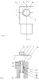
- Fig.1 is a structure diagram of a dual-prevention lock device for locking a screw in accordance with an embodiment of the present invention.
- the dual-prevention lock device for locking a screw according to the present invention comprises: a lower lock body 6; an upper lock body 1 mounted on the lower lock body 6, wherein there is a receiving space for receiving a screw to be locked that is formed between the upper lock body 1 and the lower lock body 6; and a lock core 11 mounted on the lower lock body 6.
- a lower clamping part extending into the receiving space is disposed on the lower lock body 6, and an upper clamping part extending into the receiving space is mounted in the upper lock body 1.
- the lower clamping part is pushed by the lock core 11 with the action of a key, so that the screw 3 to be locked is locked in the receiving space by the lower clamping part and the upper clamping part.
- a plurality of bolts 2 are fixed to the upper lock body 1 so that each of the bolts 2 extends into the receiving space at a respective tip thereof, thereby forming the upper clamping part described above.
- a distance between two adjacent tips of the bolts is unequal to an integral multiple of the pitch in the screw 3 to be locked, in the axial direction of the screw 3 to be locked.
- a first arc groove 1a is formed on the bottom of the upper lock body 1, and a second arc groove 6a is formed on the top of the lower lock body 6.
- the upper lock body 1 and the lower lock body 6 are connected to each other by bolts 4 so that the receiving space described above is formed by being surrounded by the first arc groove 1a and the second arc groove 6a.
- the plurality of bolts 2 are fixed to the upper lock body 1, with the tip of each bolt 2 extending downward out of the first arc groove 1a, so that the tip of each bolt 2 extends into the receiving space to form the upper clamping part described above.
- the distance between two adjacent tips of the bolts in the axial direction of the screw 3 to be locked is unequal to an integral multiple of the pitch in the screw 3 to be locked, with the result that the screw 3 can not move axially by rotation and can not be screwed by common tools, after the screw 3 to be locked by the upper clamping part and the lower clamping part, thereby preventing the dual-prevention lock device from failure caused by unprofessional people arbitrarily screwing the screw 3.
- threads which constitute the upper clamping part described above may be provided within the first arc groove, with the form of the threads differing from that of the screw 3 to be locked or the pitch of the threads unequal to an integral multiple of the pitch in the screw 3 to be locked.
- a friction plate (not shown in the drawings) which constitutes the upper clamping part may be fixed within the first arc groove 1a.
- the friction plate may be made by materials such as rubbers and brake bands.
- the lower clamping part according to the present invention can be a supporting pad 5 which is disposed within the second arc groove 6a located on the top of the lower lock body 6.
- a receiving hole 6c and a screw hole 6b which is connected to the receiving hole 6c and extends to the second arc groove 6a, are disposed in the lower lock body 6 of the present invention.
- the supporting pad 5 is disposed within the second arc groove 6a and located in the top of the screw hole 6b.
- the receiving hole 6c is coaxially communicated with the screw hole 6b, and the tail of the lock core 11 is inserted into the screw hole 6b through the receiving hole 6c and then is threadedly connected to the screw hole 6b, with the head of the lock core 11 being positioned within the receiving hole 6c.
- the supporting pad 5 has a contour shape at the top thereof matched with the screw 3 to be locked, and has a recess 5a at a bottom thereof matched with the tail of the lock core 11, such that the tail of the lock core 11 will be inserted into the recess 5a when the lock core 11 is screwed to move upwardly.
- a plurality of bolts also may be fixed to the supporting pad 5, with the tip of each bolt extending upwardly out of the supporting pad 5.
- a distance between two adjacent tips of the bolts is unequal to an integral multiple of the pitch in the screw 3 to be locked, in the axial direction of the screw 3 to be locked.
- threads may be provided on the top of the supporting pad 5, with the form of the threads differing from that of the screw 3 to be locked or the pitch of the threads unequal to an integral multiple of the pitch in the screw 3 to be locked.
- a friction plate (not shown in the drawings) may be fixed to the top of the supporting pad 5.
- the dual-prevention lock device in the present invention further comprises a lock core anti-slack device comprising a mounting hole 60 which is juxtaposed with the screw hole 6b.
- the mounting hole 60 on the bottom thereof has a side near to the receiving hole 6c, which is communicated with the receiving hole 6c, and has another side away from the receiving hole 6c, which constitutes a step along with a side wall of the receiving hole 6c. Atop of the mounting hole 60 is sealed.
- An anti-slack block 10 which is disposed within the mounting hole 60 is supported on the step, and a spring 9 is disposed within the mounting hole 60 above the anti-slack block 10.
- a notch matched with a bottom of the anti-slack block 10 is formed in the head of the lock core 11.
- the screw 3 to be locked extends through the receiving space between the upper lock body 1 and the lower lock body 6 and is disposed within the receiving space.
- the lock core 11 is operated with a special key (not shown in the drawings) to be rotated toward one direction, so that the lock core 11 moves upwardly along the screw hole 6b.
- the lock core 11 move upwardly, until the anti-slack block 10 is mated with the notch in the head of the lock core 11, thereby the lock core 11 not continuing to move upwardly.
- the key is forced upwardly to move upwardly the anti-slack block 10 by overcoming the force of the spring 9, so that the engaging action between the anti-slack block 10 and the head of the lock core disappears.
- the key is forced while the lock core 11 is rotated continuously, so that the lock core 11 continues to move upwardly.
- the supporting pad 5 is jacked up by the lock core 11, until the screw 3 to be locked is clamped with the cooperation of the plurality of the tips of the bolts and the supporting pad 5.
- the screw 3 to be locked can not move axially by rotation and the lock core 11 can not continue to rotate.
- the key is pulled slightly outwardly, so that the anti-slack block 10 is snapped into the notch in the head of the lock core to engage with the lock core with the action of the spring.
- the lock core can not rotate in any direction unless a special key is used, thereby realizing the locking of the screw 3.
- the special key is inserted into the receiving hole 6c to push inwardly the anti-slack block 10 so that the engagement between the anti-slack block 10 and the head of the lock core is removed.
- the key is forced while the lock core 11 is rotated in a reverse direction, so that the lock core 11 and the supporting pad 5 disposed on the top of the lock core 11 descend, thereby releasing the locking of the screw by the plurality of the tips of bolts and the supporting pad 5.
- the unlocking of the screw is realized.
Landscapes
- Engineering & Computer Science (AREA)
- General Engineering & Computer Science (AREA)
- Mechanical Engineering (AREA)
- Connection Of Plates (AREA)
- Clamps And Clips (AREA)
- Installation Of Indoor Wiring (AREA)
- Lock And Its Accessories (AREA)
Description
- The present invention relates to a dual-prevention lock, more particularly relates to a dual-prevention lock device for locking a screw and a method for locking the screw.
- According to the Standard GB3836.1-2010 for the Interlocking Device, it requires that the structure of an interlocking device should guaranty that its functions can not be removed easily by non-dedicated tools, to maintain the interlocking device specially for explosion protection. According to the Requirement of the Rule 445 in Safety Regulations in Coal Mine, lock devices of all switches must reliably prevent power from being transmitted unauthorizedly and prevent open operation from being performed unauthorizedly. Currently, in various explosive hazardous areas, especially in electric apparatuses used for underground coal mine, a dual-prevention lock is mounted on the locking device of the electric apparatuses for preventing open operation from being performed unauthorizedly by unprofessional person and for preventing power from being transmitted unauthorizedly (referred to as "dual-prevention"), thereby ensuring the safe usage of the electric apparatuses.
- A Chinese patent
ZL 200620024380.3 -
US 1 426 628 A shows a coupling device for coupling two shafts. - An object of the present invention is to overcome problems in the prior art, and a dual-prevention lock device for locking a screw is provided, in which the screw is locked by setting an upper clamping part and a lower clamping part so that a switch from a lock status to an unlock status is performed by jumping from "0" to "1", instead of changing continuously. Thus the dual-prevention lock device has a reliable performance and a simple structure design.
- In order to realize the object described above of the present invention, some technical solutions are provided as follows.
- A dual-prevention lock device for locking a screw which comprises: a lower lock body; an upper lock body mounted on the lower lock body, a receiving space for receiving a screw to be locked is formed between the upper lock body and the lower lock body; and a lock core mounted in the lower lock body; wherein a lower clamping part extending into said receiving space is disposed on the lower lock body, and an upper clamping part extending into said receiving space is mounted on the upper lock body; the lower clamping part is pushed by the lock core with the action of a key, so that the screw is locked securely within said receiving space by the lower clamping part and the upper clamping part. According to the invention, a plurality of bolts are fixed to the upper lock body, with the tip of each bolt extending into the receiving space to form the upper clamping part; the distance between adjacent tips of the bolts is unequal to an integral multiple of the pitch in the screw to be locked, in the axial direction of the screw to be locked.
- Or alternatively, the upper clamping part can be threads disposed on the upper lock body, with the form of the threads different from that of the screw to be locked, or the pitch of the threads unequal to an integral multiple of the pitch in the screw to be locked.
- Wherein, a first arc groove is formed in the bottom of the upper lock body, and a second arc groove is formed in the top of the lower lock body, with the receiving space formed by being surrounded by the first arc groove and the second arc groove; the lower clamping part is a supporting pad disposed in the second arc groove.
- Preferably, a plurality of bolts are so fixed to the supporting pad that the tip of each bolt extends upwardly out of the supporting pad; the distance between adjacent tips of the bolts is unequal to an integral multiple of the pitch in the screw to be locked, in the axial direction of the screw to be locked.
- Or alternatively, threads are disposed on the top of the supporting pad, with the form of the threads different from that of the screw to be locked, or the pitch of the threads unequal to an integral multiple of the pitch in the screw to be locked.
- Or alternatively, a friction plate is fixed to the top of the supporting pad.
- Preferably, a receiving hole and a screw hole which is connected to the receiving hole and extends to the supporting pad are formed in the lower lock body, so that a lock core is threadedly connected to the screw hole and the head of the lock core is disposed within the receiving hole.
- Specially, a groove matched with the tail of the lock core is formed in the bottom of the supporting pad.
- Moreover, the dual-prevention lock device further comprises a lock core anti-slack device mounted in the lower lock body. The lock core anti-slack device comprises: a mounting hole juxtaposed with the screw hole, the bottom of the mounting hole is communicated with the receiving hole to form a step, the top of the mounting hole is sealed; an anti-slack block disposed in the bottom of the mounting hole; and a spring disposed within the mounting hole above the anti-slack block; wherein a notch matched with the bottom of the anti-slack block is formed in the head of the lock core.
- In another aspect of the present invention, a method for locking a screw with a dual-prevention lock device is provided, the dual-prevention lock device can be any one of devices described above. The method comprises steps as follows:
- 1) the screw is placed between an upper clamping part of an upper lock body and a lower clamping part of a lower lock body;
- 2) a key is mated with a head of a lock core and then is rotated, so that the lock core rotates relative to the lower lock body while the lower clamping part is jacked up by the lock core;
- 3) the screw rises along with the lower clamping part, until the screw is locked by the upper clamping part and the lower clamping part.
- Or alternatively, the upper clamping part is threads disposed on the upper lock body, with the form of the threads different from that of the screw to be locked, or the pitch of the threads unequal to an integral multiple of the pitch in the screw to be locked.
- Preferably, a first arc groove is formed in the bottom of the upper lock body, and a second arc groove is formed in the top of the lower lock body, with the receiving space formed by being surrounded by the first arc groove and the second arc groove; the lower clamping part is a supporting pad disposed in the second arc groove.
- Advantages of the present invention are embodied in that:
- 1) The tips of the bolts for clamping the screw to be locked are disposed in the bottom of the upper lock body, and the distance between adjacent tips of the bolts is unequal to an integral multiple of the pitch in the screw to be locked, in the axial direction of the screw to be locked. Thus, the screw can not be rotated arbitrarily after the screw is locked by the tips of the bolts and the supporting pad, and a switch from a lock status to an unlock status is performed by jumping from "0" to "1", instead of changing continuously, ensuring a performance of the dual-prevention lock device reliable.
- 2) The dual-prevention lock device of the present invention has a simple structure design and can lock the screw simply and easily.
-
-
Fig.1 is a structure diagram showing a dual-prevention lock device for locking a screw in accordance with an embodiment of the present invention. -
Fig.2 is a sectional view taken along a section line A-A ofFig.1 . -
Fig.3 is a top view of an upper lock body ofFig.1 . -
Fig.3a is a sectional view taken along a section line B-B ofFig.3 . - A list of reference numbers:
- 1: an upper lock body
- 1a: a first arc groove
- 2: a bolt
- 3: a screw to be locked
- 4: a bolt
- 5: a supportting pad
- 5a: a recess
- 6: a lower lock body
- 6a: a second arc groove
- 6b: a screw hole
- 6c: a receiving hole
- 60: a mounting hole
- 9: a spring
- 10: an anti-slack block
- 11: a lock core
-
Fig.1 is a structure diagram of a dual-prevention lock device for locking a screw in accordance with an embodiment of the present invention. As shown inFig.1 , the dual-prevention lock device for locking a screw according to the present invention comprises: alower lock body 6; anupper lock body 1 mounted on thelower lock body 6, wherein there is a receiving space for receiving a screw to be locked that is formed between theupper lock body 1 and thelower lock body 6; and alock core 11 mounted on thelower lock body 6. A lower clamping part extending into the receiving space is disposed on thelower lock body 6, and an upper clamping part extending into the receiving space is mounted in theupper lock body 1. The lower clamping part is pushed by thelock core 11 with the action of a key, so that thescrew 3 to be locked is locked in the receiving space by the lower clamping part and the upper clamping part. - As shown in
Fig.3a , a plurality ofbolts 2 are fixed to theupper lock body 1 so that each of thebolts 2 extends into the receiving space at a respective tip thereof, thereby forming the upper clamping part described above. A distance between two adjacent tips of the bolts is unequal to an integral multiple of the pitch in thescrew 3 to be locked, in the axial direction of thescrew 3 to be locked. - Specifically, as shown in
Fig.1 and 2 , a first arc groove 1a is formed on the bottom of theupper lock body 1, and a second arc groove 6a is formed on the top of thelower lock body 6. Theupper lock body 1 and thelower lock body 6 are connected to each other bybolts 4 so that the receiving space described above is formed by being surrounded by the first arc groove 1a and the second arc groove 6a. As shown inFig.3 and 3a , the plurality ofbolts 2 are fixed to theupper lock body 1, with the tip of eachbolt 2 extending downward out of the first arc groove 1a, so that the tip of eachbolt 2 extends into the receiving space to form the upper clamping part described above. The distance between two adjacent tips of the bolts in the axial direction of thescrew 3 to be locked, is unequal to an integral multiple of the pitch in thescrew 3 to be locked, with the result that thescrew 3 can not move axially by rotation and can not be screwed by common tools, after thescrew 3 to be locked by the upper clamping part and the lower clamping part, thereby preventing the dual-prevention lock device from failure caused by unprofessional people arbitrarily screwing thescrew 3. - In the present invention, alternatively, threads (not shown in the drawings) which constitute the upper clamping part described above may be provided within the first arc groove, with the form of the threads differing from that of the
screw 3 to be locked or the pitch of the threads unequal to an integral multiple of the pitch in thescrew 3 to be locked. - In the present invention, alternatively, a friction plate (not shown in the drawings) which constitutes the upper clamping part may be fixed within the first arc groove 1a. The friction plate may be made by materials such as rubbers and brake bands.
- The lower clamping part according to the present invention can be a supporting
pad 5 which is disposed within the second arc groove 6a located on the top of thelower lock body 6. - As shown in
Fig.2 , a receiving hole 6c and ascrew hole 6b which is connected to the receiving hole 6c and extends to the second arc groove 6a, are disposed in thelower lock body 6 of the present invention. The supportingpad 5 is disposed within the second arc groove 6a and located in the top of thescrew hole 6b. - The receiving hole 6c is coaxially communicated with the
screw hole 6b, and the tail of thelock core 11 is inserted into thescrew hole 6b through the receiving hole 6c and then is threadedly connected to thescrew hole 6b, with the head of thelock core 11 being positioned within the receiving hole 6c. The supportingpad 5 has a contour shape at the top thereof matched with thescrew 3 to be locked, and has a recess 5a at a bottom thereof matched with the tail of thelock core 11, such that the tail of thelock core 11 will be inserted into the recess 5a when thelock core 11 is screwed to move upwardly. If thelock core 11 is continuously screwed to continue to move upwardly, the supportingpad 5 is jacked up by thelock core 11, thereby thescrew 3 to be locked which is disposed on the supportingpad 5 rising along with the supportingpad 5 until thescrew 3 to be locked being clamped by the supportingpad 5 and the plurality of tips of the bolts in the bottom of theupper lock body 1. Thus the locking of thescrew 3 is realized. - In the present invention, alternatively, a plurality of bolts (not shown in the drawings) also may be fixed to the supporting
pad 5, with the tip of each bolt extending upwardly out of the supportingpad 5. A distance between two adjacent tips of the bolts is unequal to an integral multiple of the pitch in thescrew 3 to be locked, in the axial direction of thescrew 3 to be locked. - Or alternatively, threads (not shown in the drawings) may be provided on the top of the supporting
pad 5, with the form of the threads differing from that of thescrew 3 to be locked or the pitch of the threads unequal to an integral multiple of the pitch in thescrew 3 to be locked. - Or alternatively, a friction plate (not shown in the drawings) may be fixed to the top of the supporting
pad 5. - Moreover, the dual-prevention lock device in the present invention further comprises a lock core anti-slack device comprising a mounting
hole 60 which is juxtaposed with thescrew hole 6b. The mountinghole 60 on the bottom thereof has a side near to the receiving hole 6c, which is communicated with the receiving hole 6c, and has another side away from the receiving hole 6c, which constitutes a step along with a side wall of the receiving hole 6c. Atop of the mountinghole 60 is sealed. Ananti-slack block 10 which is disposed within the mountinghole 60 is supported on the step, and a spring 9 is disposed within the mountinghole 60 above theanti-slack block 10. A notch matched with a bottom of theanti-slack block 10 is formed in the head of thelock core 11. - A process for locking the screw by the dual-prevention lock device will be described in detail with reference to
Fig.1 and 2 . - First, the
screw 3 to be locked extends through the receiving space between theupper lock body 1 and thelower lock body 6 and is disposed within the receiving space. - Then, the
lock core 11 is operated with a special key (not shown in the drawings) to be rotated toward one direction, so that thelock core 11 moves upwardly along thescrew hole 6b. Thelock core 11 move upwardly, until theanti-slack block 10 is mated with the notch in the head of thelock core 11, thereby thelock core 11 not continuing to move upwardly. The key is forced upwardly to move upwardly theanti-slack block 10 by overcoming the force of the spring 9, so that the engaging action between theanti-slack block 10 and the head of the lock core disappears. The key is forced while thelock core 11 is rotated continuously, so that thelock core 11 continues to move upwardly. The supportingpad 5 is jacked up by thelock core 11, until thescrew 3 to be locked is clamped with the cooperation of the plurality of the tips of the bolts and the supportingpad 5. Thus, thescrew 3 to be locked can not move axially by rotation and thelock core 11 can not continue to rotate. - Afterward, the key is pulled slightly outwardly, so that the
anti-slack block 10 is snapped into the notch in the head of the lock core to engage with the lock core with the action of the spring. At that time, the lock core can not rotate in any direction unless a special key is used, thereby realizing the locking of thescrew 3. - If the locking of the screw needs to be released, the special key is inserted into the receiving hole 6c to push inwardly the
anti-slack block 10 so that the engagement between theanti-slack block 10 and the head of the lock core is removed. The key is forced while thelock core 11 is rotated in a reverse direction, so that thelock core 11 and the supportingpad 5 disposed on the top of thelock core 11 descend, thereby releasing the locking of the screw by the plurality of the tips of bolts and the supportingpad 5. Thus the unlocking of the screw is realized. - While the present invention has been described above in detail, the present invention is not so limited. Many modifications can be made by the skilled in the art according to the principle of the present invention, thus it is should understood that various modifications made according to the principle of the present invention fall within the scope of the present invention.
Claims (10)
- A lock, comprising a screw (3) and a dual-prevention lock device for locking the screw, the dual-prevention lock device comprises:a lower lock body (6);an upper lock body (1) mounted on the lower lock body (6), a receiving space for receiving a screw (3) to be locked being formed between the upper lock body (1) and the lower lock body (6); anda lock core (11) mounted in the lower lock body (6);wherein a lower clamping part extending into the receiving space is disposed on the lower lock body (6), and an upper clamping part extending into the receiving space is mounted on the upper lock body (1);the lower clamping part is able to be pushed by the lock core (11) with the action of a key, so that the screw (3) to be locked is locked within the receiving space by the lower clamping part and the upper clamping part,characterized in thata plurality of bolts (2) are fixed to the upper lock body (1), with the tip of each bolt (2) extending into the receiving space to form the upper clamping part;a distance between adjacent tips of the bolts is unequal to an integral multiple of the pitch in the screw (3) to be locked, in the axial direction of the screw (3) to be locked.
- A lock, comprising a screw (3) and a dual-prevention lock device for locking the screw, the dual-prevention lock device comprises:a lower lock body (6);an upper lock body (1) mounted on the lower lock body (6), a receiving space for receiving a screw (3) to be locked being formed between the upper lock body (1) and the lower lock body (6); anda lock core (11) mounted in the lower lock body (6);wherein a lower clamping part extending into the receiving space is disposed on the lower lock body (6), and an upper clamping part extending into the receiving space is mounted on the upper lock body (1);the lower clamping part is able to be pushed by the lock core (11) with the action of a key, so that the screw (3) to be locked is locked within the receiving space by the lower clamping part and the upper clamping part,characterized in thatthe upper clamping part is threads disposed on the upper lock body (1), with the form of the threads different from that of the screw to be locked, or the pitch of the threads unequal to an integral multiple of the pitch of the screw (3) to be locked.
- The lock according to any one of Claims 1-2, characterized in that a first arcuate groove (1a) is formed in the bottom of the upper lock body (1), and a second arcuate groove (6a) is formed in the top of the lower lock body (6), with the receiving space formed by being surrounded by the first arcuate groove (1a) and the second arcuate groove (6a);
the lower clamping part is a supporting pad (5) disposed in the second arcuate groove (6a). - The lock according to Claim 3, characterized in that a plurality of bolts are so fixed to the supporting pad (5) that the tip of each bolt extends upwardly out of the supporting pad (5);
the distance between adjacent tips of the bolts is unequal to an integral multiple of the pitch in the screw (3) to be locked, in the axial direction of the screw (3) to be locked. - The lock according to Claim 3, characterized in that threads are disposed on the top of the supporting pad (5), with the form of the threads different from that of the screw to locked, or the pitch of the threads unequal to an integral multiple of the pitch of the screw (3) to be locked.
- The lock according to Claim 3, characterized in that a friction plate is fixed to the top of the supporting pad (5).
- The lock according to Claim 3, characterized in that a receiving hole (6c) and a screw hole (6b) which is connected to the receiving hole (6c) and extends to the supporting pad (5) are formed in the lower lock body (6), so that the lock core (11) is threadedly connected to the screw hole (6b) and the head of the lock core (11) is placed within the receiving hole (6c).
- The lock according to Claim 7, characterized in that a recess (5a) matched with the tail of the lock core (11) is formed in the bottom of the supporting pad (5).
- The lock according to Claim 8, characterized in that it further comprises a lock core anti-slack device mounted in the lower lock body (6), the lock core anti-slack device comprising:a mounting hole (60) juxtaposed with the screw hole (6b), the bottom of which is communicated with the receiving hole (6c) to form a step, and the top of the mounting hole is sealed;an anti-slack block (10) disposed in the bottom of the mounting hole (60);a spring (9) disposed within the mounting hole (60) above the anti-slack block (10);wherein a notch matched with the bottom of the anti-slack block (10) is formed in the head of the lock core (11).
- A method for locking a screw of a lock, characterized in that the lock is a lock of any one of Claims 1-9, the method comprising the following steps:1) the screw being disposed between the upper clamping part of the upper lock body (1) and the lower clamping part of the lower lock body (6);2) a key being mated with a head of the lock core (11) and then being rotated, such that the lock core (11) rotating relative to the lower lock body (6) while the lower clamping part being jacked up by the lock core (11);3) the screw rising along with the lower clamping part, until the screw being locked by the upper clamping part and the lower clamping part.
Priority Applications (1)
| Application Number | Priority Date | Filing Date | Title |
|---|---|---|---|
| PL13816899T PL2871309T3 (en) | 2012-07-09 | 2013-06-20 | A dual-prevention lock device for locking a screw and a method for locking the screw |
Applications Claiming Priority (2)
| Application Number | Priority Date | Filing Date | Title |
|---|---|---|---|
| CN201210237949.4A CN103541606B (en) | 2012-07-09 | 2012-07-09 | A kind of two anti-locking devices of tie down screw and method of tie down screw thereof of being used for |
| PCT/CN2013/077557 WO2014008805A1 (en) | 2012-07-09 | 2013-06-20 | Dual-prevention lock device for locking bolt and method for locking bolt |
Publications (3)
| Publication Number | Publication Date |
|---|---|
| EP2871309A1 EP2871309A1 (en) | 2015-05-13 |
| EP2871309A4 EP2871309A4 (en) | 2016-03-23 |
| EP2871309B1 true EP2871309B1 (en) | 2018-08-15 |
Family
ID=49915384
Family Applications (1)
| Application Number | Title | Priority Date | Filing Date |
|---|---|---|---|
| EP13816899.2A Not-in-force EP2871309B1 (en) | 2012-07-09 | 2013-06-20 | A dual-prevention lock device for locking a screw and a method for locking the screw |
Country Status (11)
| Country | Link |
|---|---|
| US (1) | US10072697B2 (en) |
| EP (1) | EP2871309B1 (en) |
| CN (1) | CN103541606B (en) |
| AU (1) | AU2013289710B2 (en) |
| CA (1) | CA2863446C (en) |
| CO (1) | CO7101209A2 (en) |
| EA (1) | EA025320B1 (en) |
| IN (1) | IN2014KN01671A (en) |
| PL (1) | PL2871309T3 (en) |
| WO (1) | WO2014008805A1 (en) |
| ZA (1) | ZA201405869B (en) |
Families Citing this family (3)
| Publication number | Priority date | Publication date | Assignee | Title |
|---|---|---|---|---|
| CN104033468B (en) * | 2014-06-19 | 2015-12-02 | 宁波浩渤工贸有限公司 | A kind of Anti-extrusion bolt |
| CN108498125B (en) * | 2018-03-21 | 2020-06-30 | 李福顺 | Automatic locking mechanism device for general surgery department clinical operation retractor |
| FR3079343B1 (en) * | 2018-03-22 | 2021-07-09 | Schneider Electric Ind Sas | METHOD OF CONSIGNING A FUNCTION OF AN ELECTRICAL APPARATUS AND ELECTRICAL APPARATUS IMPLEMENTING THIS PROCESS |
Citations (1)
| Publication number | Priority date | Publication date | Assignee | Title |
|---|---|---|---|---|
| US1426628A (en) * | 1919-10-08 | 1922-08-22 | Denison Peter | Coupling |
Family Cites Families (41)
| Publication number | Priority date | Publication date | Assignee | Title |
|---|---|---|---|---|
| US289334A (en) * | 1883-11-27 | Adolph f | ||
| US1039576A (en) * | 1910-06-28 | 1912-09-24 | Mueller Mfg Co H | Seal for pipe-couplings. |
| US1231164A (en) * | 1913-02-24 | 1917-06-26 | William H Jahns | Valve-lock. |
| US1273922A (en) * | 1916-10-17 | 1918-07-30 | Alexander J Prattinger | Line-clutch. |
| US1406315A (en) * | 1921-05-13 | 1922-02-14 | James B Whittaker | Nut and bolt lock |
| US1934327A (en) * | 1932-10-21 | 1933-11-07 | John H Ridder | Locking device for pump shafts and the like |
| US1963667A (en) * | 1934-01-15 | 1934-06-19 | Mercier Joseph Robert | Interlocking bolt and nut |
| US2144837A (en) * | 1938-04-22 | 1939-01-24 | C F Noltimier | Lock for outboard motors |
| US2273102A (en) * | 1941-02-14 | 1942-02-17 | Harry A Harris | Grip bolt |
| FR1111508A (en) * | 1952-06-20 | 1956-03-01 | Improvements to threaded parts | |
| US2910315A (en) * | 1957-04-22 | 1959-10-27 | Oliver L Stevens | Locking means |
| US3501993A (en) * | 1968-12-17 | 1970-03-24 | Henry F Swenson | Setscrew with rotatable plastic end |
| US3731504A (en) * | 1971-04-30 | 1973-05-08 | J Belknap | Locking device for securing an outboard motor to a boat |
| US3987653A (en) * | 1975-11-06 | 1976-10-26 | Reginald Lyon | Looped cable locking device |
| US4506917A (en) * | 1982-07-22 | 1985-03-26 | Interfit, Inc. | Pipe connection fitting |
| US4912949A (en) * | 1986-02-03 | 1990-04-03 | Bowers Arvid M | Lock clamp |
| US4844397A (en) * | 1988-06-27 | 1989-07-04 | C. R. Bard, Inc. | Intravenous pole clamp |
| US4986457A (en) * | 1990-02-08 | 1991-01-22 | Lucky Line Products | Closed loop cable system |
| US5266057A (en) * | 1990-03-29 | 1993-11-30 | Monster Cable Products, Inc. | Electronic power distribution device |
| US5813809A (en) * | 1997-04-28 | 1998-09-29 | Wyko Corporation | Polymeric insert with crush-formed threads for mating with threaded surface |
| US6023800A (en) * | 1997-05-09 | 2000-02-15 | Midmark Corporation | Removable accessory for a surgical table |
| KR100349743B1 (en) * | 1999-12-30 | 2002-08-22 | 현대자동차주식회사 | Dual locking structure of trunk lid for burglarproof |
| JP3278114B2 (en) * | 2000-02-10 | 2002-04-30 | エス ケイ エフ メカン アーベー | Lock nut |
| CN2435481Y (en) * | 2000-08-08 | 2001-06-20 | 杨小锋 | Gate valve lock |
| DE10055231A1 (en) | 2000-11-08 | 2002-05-29 | Mauersberger Hans Georg | Locking nut has part of its thread on flexible tongue which is pressed against bolt thread by clamping screw |
| CN2526416Y (en) * | 2000-11-29 | 2002-12-18 | 郭春平 | Safety lock |
| DE20020996U1 (en) * | 2000-12-12 | 2001-03-08 | FMS Förder- und Montage-Systeme Schmalzhofer GmbH, 75031 Eppingen | Connector device for profiles |
| US7226393B2 (en) * | 2001-01-19 | 2007-06-05 | Nautilus, Inc. | Exercise bicycle |
| DE10153343A1 (en) | 2001-10-29 | 2003-05-15 | Bosch Rexroth Teknik Ab Stockholm | Stop element for mounting on a pole |
| DE10240235A1 (en) * | 2002-08-28 | 2004-03-11 | Thyssenkrupp Presta Ag | Locking device for two components slidably mounted relative to each other |
| DE20314117U1 (en) | 2003-09-11 | 2004-01-08 | Hofmann, Gerhard | Operating device for a telescopic security door lock rose comprises a telescopic security rose telescopically screwed into a cylinder housing depending on the wall thickness of the door so it lies flush with the front end of the lock |
| US7040832B2 (en) * | 2004-01-20 | 2006-05-09 | Wu-Hong Hsieh | Locking device to secure a telescopic tube assembly |
| FR2876755B1 (en) * | 2004-10-20 | 2007-01-26 | Pcm Pompes Sa | PUMPING DEVICE WITH PROGRESSIVE CAVITY PUMP |
| US7731141B2 (en) * | 2005-04-06 | 2010-06-08 | Peter Schuerch | Surgical appliance post clamp for surgical tables |
| US7607876B2 (en) * | 2006-03-10 | 2009-10-27 | Hall David R | Locking mechanism for a high-pressure, high-temperature press |
| CN2898216Y (en) * | 2006-05-09 | 2007-05-09 | 郭春平 | Safety lock |
| ATE510326T1 (en) * | 2009-02-25 | 2011-06-15 | Nexans | DEVICE FOR CONNECTING TWO ELECTRICAL CONDUCTORS |
| JP5480566B2 (en) * | 2009-08-31 | 2014-04-23 | ローランド株式会社 | Clamp for instrument stand |
| CN201614811U (en) | 2010-01-28 | 2010-10-27 | 于步胜 | Multi-defense lock |
| US8313275B2 (en) * | 2010-08-13 | 2012-11-20 | Ohio Valley Precision, Inc. | Wedge fastener |
| CN202024055U (en) * | 2011-04-08 | 2011-11-02 | 吉多思实业(深圳)有限公司 | Fixing device |
-
2012
- 2012-07-09 CN CN201210237949.4A patent/CN103541606B/en active Active
-
2013
- 2013-06-20 CA CA2863446A patent/CA2863446C/en not_active Expired - Fee Related
- 2013-06-20 WO PCT/CN2013/077557 patent/WO2014008805A1/en not_active Ceased
- 2013-06-20 US US14/381,135 patent/US10072697B2/en active Active
- 2013-06-20 PL PL13816899T patent/PL2871309T3/en unknown
- 2013-06-20 EA EA201400821A patent/EA025320B1/en not_active IP Right Cessation
- 2013-06-20 AU AU2013289710A patent/AU2013289710B2/en not_active Ceased
- 2013-06-20 EP EP13816899.2A patent/EP2871309B1/en not_active Not-in-force
-
2014
- 2014-07-18 CO CO14156329A patent/CO7101209A2/en unknown
- 2014-08-11 ZA ZA2014/05869A patent/ZA201405869B/en unknown
- 2014-08-12 IN IN1671KON2014 patent/IN2014KN01671A/en unknown
Patent Citations (1)
| Publication number | Priority date | Publication date | Assignee | Title |
|---|---|---|---|---|
| US1426628A (en) * | 1919-10-08 | 1922-08-22 | Denison Peter | Coupling |
Also Published As
| Publication number | Publication date |
|---|---|
| CA2863446C (en) | 2018-11-13 |
| ZA201405869B (en) | 2015-11-25 |
| CO7101209A2 (en) | 2014-10-31 |
| CN103541606B (en) | 2016-05-04 |
| AU2013289710B2 (en) | 2017-04-20 |
| AU2013289710A1 (en) | 2014-08-21 |
| PL2871309T3 (en) | 2019-04-30 |
| CA2863446A1 (en) | 2014-01-16 |
| EA201400821A1 (en) | 2014-11-28 |
| US20150023758A1 (en) | 2015-01-22 |
| EP2871309A4 (en) | 2016-03-23 |
| WO2014008805A1 (en) | 2014-01-16 |
| EA025320B1 (en) | 2016-12-30 |
| CN103541606A (en) | 2014-01-29 |
| US10072697B2 (en) | 2018-09-11 |
| IN2014KN01671A (en) | 2015-10-23 |
| EP2871309A1 (en) | 2015-05-13 |
Similar Documents
| Publication | Publication Date | Title |
|---|---|---|
| US9362672B1 (en) | Lockable socket | |
| US10072697B2 (en) | Dual-prevention lock device for locking a screw and a method for locking the screw | |
| CN101761539A (en) | Double-locking automatic latch | |
| CA3048878C (en) | Tolerance ring in external energy absorber | |
| EP0529172B1 (en) | Panel fastener, positive locking and status indicator | |
| CN105539886B (en) | A kind of spring control separates unlocking mechanism | |
| CN108808339B (en) | Pressing plate locking device and power wiring device | |
| CN103373481B (en) | A kind of aerospace unit locking releasing mechanism | |
| CN103633503B (en) | A kind of retaining mechanism of metal bolt | |
| CN203085398U (en) | Emergency stop button interlocking mechanism | |
| CN202745076U (en) | Inspection well cover connection structure assembly | |
| CN109989626B (en) | Safety lock and operation method thereof | |
| CN108498972B (en) | Detachable novel anti-falling self-locking device | |
| CN202544570U (en) | Biguardian lock | |
| CN204050708U (en) | A kind of preact formula safety glass breaks glass device | |
| CN217054705U (en) | Electromagnetic lock with internal push rod | |
| TWI682821B (en) | Drop arm reset method | |
| CN102518633A (en) | Screw assembly | |
| CN218849348U (en) | Key type rotary reset emergency stop switch | |
| CN107386806B (en) | Safety device interlocked by mechanical key | |
| JP2017224555A (en) | Emergency stop pushbutton switch | |
| CN223651295U (en) | An explosion-proof button | |
| CN107834247B (en) | One-key pop-up patch board | |
| CN202871618U (en) | Locking device and unlocking member | |
| CN107548328B (en) | Plumbing arm resetting method |
Legal Events
| Date | Code | Title | Description |
|---|---|---|---|
| PUAI | Public reference made under article 153(3) epc to a published international application that has entered the european phase |
Free format text: ORIGINAL CODE: 0009012 |
|
| 17P | Request for examination filed |
Effective date: 20141219 |
|
| AK | Designated contracting states |
Kind code of ref document: A1 Designated state(s): AL AT BE BG CH CY CZ DE DK EE ES FI FR GB GR HR HU IE IS IT LI LT LU LV MC MK MT NL NO PL PT RO RS SE SI SK SM TR |
|
| AX | Request for extension of the european patent |
Extension state: BA ME |
|
| DAX | Request for extension of the european patent (deleted) | ||
| RA4 | Supplementary search report drawn up and despatched (corrected) |
Effective date: 20160218 |
|
| RIC1 | Information provided on ipc code assigned before grant |
Ipc: E05B 65/00 20060101AFI20160212BHEP Ipc: E05B 63/00 20060101ALI20160212BHEP Ipc: F16B 39/02 20060101ALI20160212BHEP Ipc: E05B 15/00 20060101ALI20160212BHEP |
|
| STAA | Information on the status of an ep patent application or granted ep patent |
Free format text: STATUS: EXAMINATION IS IN PROGRESS |
|
| 17Q | First examination report despatched |
Effective date: 20170207 |
|
| GRAP | Despatch of communication of intention to grant a patent |
Free format text: ORIGINAL CODE: EPIDOSNIGR1 |
|
| STAA | Information on the status of an ep patent application or granted ep patent |
Free format text: STATUS: GRANT OF PATENT IS INTENDED |
|
| INTG | Intention to grant announced |
Effective date: 20180302 |
|
| GRAS | Grant fee paid |
Free format text: ORIGINAL CODE: EPIDOSNIGR3 |
|
| GRAA | (expected) grant |
Free format text: ORIGINAL CODE: 0009210 |
|
| STAA | Information on the status of an ep patent application or granted ep patent |
Free format text: STATUS: THE PATENT HAS BEEN GRANTED |
|
| AK | Designated contracting states |
Kind code of ref document: B1 Designated state(s): AL AT BE BG CH CY CZ DE DK EE ES FI FR GB GR HR HU IE IS IT LI LT LU LV MC MK MT NL NO PL PT RO RS SE SI SK SM TR |
|
| REG | Reference to a national code |
Ref country code: CH Ref legal event code: EP Ref country code: GB Ref legal event code: FG4D Ref country code: AT Ref legal event code: REF Ref document number: 1029952 Country of ref document: AT Kind code of ref document: T Effective date: 20180815 |
|
| REG | Reference to a national code |
Ref country code: IE Ref legal event code: FG4D |
|
| REG | Reference to a national code |
Ref country code: DE Ref legal event code: R096 Ref document number: 602013042128 Country of ref document: DE |
|
| REG | Reference to a national code |
Ref country code: NL Ref legal event code: MP Effective date: 20180815 |
|
| REG | Reference to a national code |
Ref country code: LT Ref legal event code: MG4D |
|
| REG | Reference to a national code |
Ref country code: AT Ref legal event code: MK05 Ref document number: 1029952 Country of ref document: AT Kind code of ref document: T Effective date: 20180815 |
|
| PG25 | Lapsed in a contracting state [announced via postgrant information from national office to epo] |
Ref country code: NO Free format text: LAPSE BECAUSE OF FAILURE TO SUBMIT A TRANSLATION OF THE DESCRIPTION OR TO PAY THE FEE WITHIN THE PRESCRIBED TIME-LIMIT Effective date: 20181115 Ref country code: GR Free format text: LAPSE BECAUSE OF FAILURE TO SUBMIT A TRANSLATION OF THE DESCRIPTION OR TO PAY THE FEE WITHIN THE PRESCRIBED TIME-LIMIT Effective date: 20181116 Ref country code: FI Free format text: LAPSE BECAUSE OF FAILURE TO SUBMIT A TRANSLATION OF THE DESCRIPTION OR TO PAY THE FEE WITHIN THE PRESCRIBED TIME-LIMIT Effective date: 20180815 Ref country code: SE Free format text: LAPSE BECAUSE OF FAILURE TO SUBMIT A TRANSLATION OF THE DESCRIPTION OR TO PAY THE FEE WITHIN THE PRESCRIBED TIME-LIMIT Effective date: 20180815 Ref country code: RS Free format text: LAPSE BECAUSE OF FAILURE TO SUBMIT A TRANSLATION OF THE DESCRIPTION OR TO PAY THE FEE WITHIN THE PRESCRIBED TIME-LIMIT Effective date: 20180815 Ref country code: LT Free format text: LAPSE BECAUSE OF FAILURE TO SUBMIT A TRANSLATION OF THE DESCRIPTION OR TO PAY THE FEE WITHIN THE PRESCRIBED TIME-LIMIT Effective date: 20180815 Ref country code: AT Free format text: LAPSE BECAUSE OF FAILURE TO SUBMIT A TRANSLATION OF THE DESCRIPTION OR TO PAY THE FEE WITHIN THE PRESCRIBED TIME-LIMIT Effective date: 20180815 Ref country code: IS Free format text: LAPSE BECAUSE OF FAILURE TO SUBMIT A TRANSLATION OF THE DESCRIPTION OR TO PAY THE FEE WITHIN THE PRESCRIBED TIME-LIMIT Effective date: 20181215 Ref country code: NL Free format text: LAPSE BECAUSE OF FAILURE TO SUBMIT A TRANSLATION OF THE DESCRIPTION OR TO PAY THE FEE WITHIN THE PRESCRIBED TIME-LIMIT Effective date: 20180815 Ref country code: BG Free format text: LAPSE BECAUSE OF FAILURE TO SUBMIT A TRANSLATION OF THE DESCRIPTION OR TO PAY THE FEE WITHIN THE PRESCRIBED TIME-LIMIT Effective date: 20181115 |
|
| PG25 | Lapsed in a contracting state [announced via postgrant information from national office to epo] |
Ref country code: AL Free format text: LAPSE BECAUSE OF FAILURE TO SUBMIT A TRANSLATION OF THE DESCRIPTION OR TO PAY THE FEE WITHIN THE PRESCRIBED TIME-LIMIT Effective date: 20180815 Ref country code: LV Free format text: LAPSE BECAUSE OF FAILURE TO SUBMIT A TRANSLATION OF THE DESCRIPTION OR TO PAY THE FEE WITHIN THE PRESCRIBED TIME-LIMIT Effective date: 20180815 Ref country code: HR Free format text: LAPSE BECAUSE OF FAILURE TO SUBMIT A TRANSLATION OF THE DESCRIPTION OR TO PAY THE FEE WITHIN THE PRESCRIBED TIME-LIMIT Effective date: 20180815 |
|
| PG25 | Lapsed in a contracting state [announced via postgrant information from national office to epo] |
Ref country code: EE Free format text: LAPSE BECAUSE OF FAILURE TO SUBMIT A TRANSLATION OF THE DESCRIPTION OR TO PAY THE FEE WITHIN THE PRESCRIBED TIME-LIMIT Effective date: 20180815 Ref country code: ES Free format text: LAPSE BECAUSE OF FAILURE TO SUBMIT A TRANSLATION OF THE DESCRIPTION OR TO PAY THE FEE WITHIN THE PRESCRIBED TIME-LIMIT Effective date: 20180815 Ref country code: RO Free format text: LAPSE BECAUSE OF FAILURE TO SUBMIT A TRANSLATION OF THE DESCRIPTION OR TO PAY THE FEE WITHIN THE PRESCRIBED TIME-LIMIT Effective date: 20180815 Ref country code: CZ Free format text: LAPSE BECAUSE OF FAILURE TO SUBMIT A TRANSLATION OF THE DESCRIPTION OR TO PAY THE FEE WITHIN THE PRESCRIBED TIME-LIMIT Effective date: 20180815 Ref country code: IT Free format text: LAPSE BECAUSE OF FAILURE TO SUBMIT A TRANSLATION OF THE DESCRIPTION OR TO PAY THE FEE WITHIN THE PRESCRIBED TIME-LIMIT Effective date: 20180815 |
|
| REG | Reference to a national code |
Ref country code: DE Ref legal event code: R097 Ref document number: 602013042128 Country of ref document: DE |
|
| PG25 | Lapsed in a contracting state [announced via postgrant information from national office to epo] |
Ref country code: SM Free format text: LAPSE BECAUSE OF FAILURE TO SUBMIT A TRANSLATION OF THE DESCRIPTION OR TO PAY THE FEE WITHIN THE PRESCRIBED TIME-LIMIT Effective date: 20180815 Ref country code: DK Free format text: LAPSE BECAUSE OF FAILURE TO SUBMIT A TRANSLATION OF THE DESCRIPTION OR TO PAY THE FEE WITHIN THE PRESCRIBED TIME-LIMIT Effective date: 20180815 Ref country code: SK Free format text: LAPSE BECAUSE OF FAILURE TO SUBMIT A TRANSLATION OF THE DESCRIPTION OR TO PAY THE FEE WITHIN THE PRESCRIBED TIME-LIMIT Effective date: 20180815 |
|
| PLBE | No opposition filed within time limit |
Free format text: ORIGINAL CODE: 0009261 |
|
| STAA | Information on the status of an ep patent application or granted ep patent |
Free format text: STATUS: NO OPPOSITION FILED WITHIN TIME LIMIT |
|
| 26N | No opposition filed |
Effective date: 20190516 |
|
| PGFP | Annual fee paid to national office [announced via postgrant information from national office to epo] |
Ref country code: PL Payment date: 20190610 Year of fee payment: 7 |
|
| PG25 | Lapsed in a contracting state [announced via postgrant information from national office to epo] |
Ref country code: SI Free format text: LAPSE BECAUSE OF FAILURE TO SUBMIT A TRANSLATION OF THE DESCRIPTION OR TO PAY THE FEE WITHIN THE PRESCRIBED TIME-LIMIT Effective date: 20180815 |
|
| PGFP | Annual fee paid to national office [announced via postgrant information from national office to epo] |
Ref country code: TR Payment date: 20190612 Year of fee payment: 7 |
|
| REG | Reference to a national code |
Ref country code: DE Ref legal event code: R119 Ref document number: 602013042128 Country of ref document: DE |
|
| PG25 | Lapsed in a contracting state [announced via postgrant information from national office to epo] |
Ref country code: MC Free format text: LAPSE BECAUSE OF FAILURE TO SUBMIT A TRANSLATION OF THE DESCRIPTION OR TO PAY THE FEE WITHIN THE PRESCRIBED TIME-LIMIT Effective date: 20180815 |
|
| REG | Reference to a national code |
Ref country code: CH Ref legal event code: PL |
|
| GBPC | Gb: european patent ceased through non-payment of renewal fee |
Effective date: 20190620 |
|
| REG | Reference to a national code |
Ref country code: BE Ref legal event code: MM Effective date: 20190630 |
|
| PG25 | Lapsed in a contracting state [announced via postgrant information from national office to epo] |
Ref country code: DE Free format text: LAPSE BECAUSE OF NON-PAYMENT OF DUE FEES Effective date: 20200101 Ref country code: GB Free format text: LAPSE BECAUSE OF NON-PAYMENT OF DUE FEES Effective date: 20190620 Ref country code: IE Free format text: LAPSE BECAUSE OF NON-PAYMENT OF DUE FEES Effective date: 20190620 |
|
| PG25 | Lapsed in a contracting state [announced via postgrant information from national office to epo] |
Ref country code: LU Free format text: LAPSE BECAUSE OF NON-PAYMENT OF DUE FEES Effective date: 20190620 Ref country code: CH Free format text: LAPSE BECAUSE OF NON-PAYMENT OF DUE FEES Effective date: 20190630 Ref country code: LI Free format text: LAPSE BECAUSE OF NON-PAYMENT OF DUE FEES Effective date: 20190630 Ref country code: BE Free format text: LAPSE BECAUSE OF NON-PAYMENT OF DUE FEES Effective date: 20190630 |
|
| PG25 | Lapsed in a contracting state [announced via postgrant information from national office to epo] |
Ref country code: FR Free format text: LAPSE BECAUSE OF NON-PAYMENT OF DUE FEES Effective date: 20190630 Ref country code: PT Free format text: LAPSE BECAUSE OF FAILURE TO SUBMIT A TRANSLATION OF THE DESCRIPTION OR TO PAY THE FEE WITHIN THE PRESCRIBED TIME-LIMIT Effective date: 20181215 |
|
| PG25 | Lapsed in a contracting state [announced via postgrant information from national office to epo] |
Ref country code: CY Free format text: LAPSE BECAUSE OF FAILURE TO SUBMIT A TRANSLATION OF THE DESCRIPTION OR TO PAY THE FEE WITHIN THE PRESCRIBED TIME-LIMIT Effective date: 20180815 |
|
| PG25 | Lapsed in a contracting state [announced via postgrant information from national office to epo] |
Ref country code: HU Free format text: LAPSE BECAUSE OF FAILURE TO SUBMIT A TRANSLATION OF THE DESCRIPTION OR TO PAY THE FEE WITHIN THE PRESCRIBED TIME-LIMIT; INVALID AB INITIO Effective date: 20130620 Ref country code: MT Free format text: LAPSE BECAUSE OF FAILURE TO SUBMIT A TRANSLATION OF THE DESCRIPTION OR TO PAY THE FEE WITHIN THE PRESCRIBED TIME-LIMIT Effective date: 20180815 |
|
| PG25 | Lapsed in a contracting state [announced via postgrant information from national office to epo] |
Ref country code: TR Free format text: LAPSE BECAUSE OF NON-PAYMENT OF DUE FEES Effective date: 20200620 Ref country code: MK Free format text: LAPSE BECAUSE OF FAILURE TO SUBMIT A TRANSLATION OF THE DESCRIPTION OR TO PAY THE FEE WITHIN THE PRESCRIBED TIME-LIMIT Effective date: 20180815 |
|
| PG25 | Lapsed in a contracting state [announced via postgrant information from national office to epo] |
Ref country code: PL Free format text: LAPSE BECAUSE OF NON-PAYMENT OF DUE FEES Effective date: 20200620 |