JP5480566B2 - Clamp for instrument stand - Google Patents

Clamp for instrument stand Download PDF

Info

Publication number
JP5480566B2
JP5480566B2 JP2009200977A JP2009200977A JP5480566B2 JP 5480566 B2 JP5480566 B2 JP 5480566B2 JP 2009200977 A JP2009200977 A JP 2009200977A JP 2009200977 A JP2009200977 A JP 2009200977A JP 5480566 B2 JP5480566 B2 JP 5480566B2
Authority
JP
Japan
Prior art keywords
pipe
clamp
fastening
sleeve
outer peripheral
Prior art date
Legal status (The legal status is an assumption and is not a legal conclusion. Google has not performed a legal analysis and makes no representation as to the accuracy of the status listed.)
Expired - Fee Related
Application number
JP2009200977A
Other languages
Japanese (ja)
Other versions
JP2011053370A (en
JP2011053370A5 (en
Inventor
良彰 森
Current Assignee (The listed assignees may be inaccurate. Google has not performed a legal analysis and makes no representation or warranty as to the accuracy of the list.)
Roland Corp
Original Assignee
Roland Corp
Priority date (The priority date is an assumption and is not a legal conclusion. Google has not performed a legal analysis and makes no representation as to the accuracy of the date listed.)
Filing date
Publication date
Application filed by Roland Corp filed Critical Roland Corp
Priority to JP2009200977A priority Critical patent/JP5480566B2/en
Priority to US12/829,322 priority patent/US8662461B2/en
Priority to CN201010269383.4A priority patent/CN102005203B/en
Publication of JP2011053370A publication Critical patent/JP2011053370A/en
Publication of JP2011053370A5 publication Critical patent/JP2011053370A5/ja
Application granted granted Critical
Publication of JP5480566B2 publication Critical patent/JP5480566B2/en
Expired - Fee Related legal-status Critical Current
Anticipated expiration legal-status Critical

Links

Images

Classifications

    • FMECHANICAL ENGINEERING; LIGHTING; HEATING; WEAPONS; BLASTING
    • F16ENGINEERING ELEMENTS AND UNITS; GENERAL MEASURES FOR PRODUCING AND MAINTAINING EFFECTIVE FUNCTIONING OF MACHINES OR INSTALLATIONS; THERMAL INSULATION IN GENERAL
    • F16BDEVICES FOR FASTENING OR SECURING CONSTRUCTIONAL ELEMENTS OR MACHINE PARTS TOGETHER, e.g. NAILS, BOLTS, CIRCLIPS, CLAMPS, CLIPS OR WEDGES; JOINTS OR JOINTING
    • F16B7/00Connections of rods or tubes, e.g. of non-circular section, mutually, including resilient connections
    • F16B7/04Clamping or clipping connections
    • F16B7/044Clamping or clipping connections for rods or tubes being in angled relationship
    • F16B7/048Clamping or clipping connections for rods or tubes being in angled relationship for rods or for tubes without using the innerside thereof
    • F16B7/0493Clamping or clipping connections for rods or tubes being in angled relationship for rods or for tubes without using the innerside thereof forming a crossed-over connection
    • FMECHANICAL ENGINEERING; LIGHTING; HEATING; WEAPONS; BLASTING
    • F16ENGINEERING ELEMENTS AND UNITS; GENERAL MEASURES FOR PRODUCING AND MAINTAINING EFFECTIVE FUNCTIONING OF MACHINES OR INSTALLATIONS; THERMAL INSULATION IN GENERAL
    • F16BDEVICES FOR FASTENING OR SECURING CONSTRUCTIONAL ELEMENTS OR MACHINE PARTS TOGETHER, e.g. NAILS, BOLTS, CIRCLIPS, CLAMPS, CLIPS OR WEDGES; JOINTS OR JOINTING
    • F16B2/00Friction-grip releasable fastenings
    • F16B2/02Clamps, i.e. with gripping action effected by positive means other than the inherent resistance to deformation of the material of the fastening
    • F16B2/06Clamps, i.e. with gripping action effected by positive means other than the inherent resistance to deformation of the material of the fastening external, i.e. with contracting action
    • F16B2/10Clamps, i.e. with gripping action effected by positive means other than the inherent resistance to deformation of the material of the fastening external, i.e. with contracting action using pivoting jaws
    • YGENERAL TAGGING OF NEW TECHNOLOGICAL DEVELOPMENTS; GENERAL TAGGING OF CROSS-SECTIONAL TECHNOLOGIES SPANNING OVER SEVERAL SECTIONS OF THE IPC; TECHNICAL SUBJECTS COVERED BY FORMER USPC CROSS-REFERENCE ART COLLECTIONS [XRACs] AND DIGESTS
    • Y10TECHNICAL SUBJECTS COVERED BY FORMER USPC
    • Y10TTECHNICAL SUBJECTS COVERED BY FORMER US CLASSIFICATION
    • Y10T403/00Joints and connections
    • Y10T403/32Articulated members
    • Y10T403/32254Lockable at fixed position
    • Y10T403/32426Plural distinct positions

Description

本発明は、楽器スタンド用のクランプに関し、特に、直線形状のパイプ及び湾曲形状のパイプの双方を確実に固定することができると共に、位置調整を円滑に行うことができる楽器スタンド用のクランプに関するものである。   The present invention relates to a clamp for a musical instrument stand, and more particularly, to a clamp for a musical instrument stand that can securely fix both a straight pipe and a curved pipe and can adjust the position smoothly. It is.

演奏者により演奏されるドラムやシンバル等の楽器は、楽器用のスタンドに取り付けられることで、演奏者の好みに応じた位置に配置される。この楽器用のスタンドは、複数のパイプを連結することにより構成されており、それら複数のパイプを連結する連結部材の位置を変更することで、楽器が設置される高さ、角度、演奏者との距離を調整することができる。   An instrument such as a drum or a cymbal played by the performer is attached to a stand for the instrument, and is arranged at a position according to the performer's preference. This musical instrument stand is configured by connecting a plurality of pipes, and by changing the position of a connecting member that connects the plurality of pipes, the height, angle, player and The distance can be adjusted.

また、連結部材としては、例えば、実開平05−38691号公報に開示されるように、金属の鋳造品からなる一対のパイプ挟持用ブロック(基部および締付部)を備え、一対のパイプ挟持用ブロックの互いに対向する面(当て面および締付面)の中央部にそれぞれ半円状凹入部(凹部)が形成されたパイプ保持部を備えるパイプホルダ(楽器スタンド用のクランプ)がある。   Further, as a connecting member, for example, as disclosed in Japanese Utility Model Laid-Open No. 05-38691, a pair of pipe clamping blocks (base part and clamping part) made of a cast metal product are provided, and a pair of pipe clamping parts is provided. There is a pipe holder (a clamp for a musical instrument stand) provided with a pipe holding part in which a semicircular recess (recess) is formed at the center of mutually opposing surfaces (abutment surface and fastening surface) of the block.

実開平05−38691(段落[0044])ACT 05-38691 (paragraph [0044])

しかしながら、上述したパイプホルダは、金属の鋳造品で構成されているので、パイプに当接させる面をパイプの形状に合わせて変形させることができない。そのため、直線形状のパイプを保持するために成形されたパイプホルダで湾曲形状のパイプを保持しようとする場合、パイプホルダとパイプとの接触面積が小さく、パイプを挟持固定する際の圧力がパイプへ十分に伝達されないので、パイプの保持力が不足するという問題点があった。さらに、楽器の設置位置を変更するために、楽器を支持すると共にパイプホルダに固定される楽器支持アームの連結位置を調整する際、パイプホルダにパイプを緩挿させたままの状態でパイプホルダをパイプに沿って摺動させると、パイプホルダとパイプとの当接面に強い摩擦力が生じるので、パイプホルダを摺動させる際に、強い力を加える必要があるだけでなく、大きな騒音を発生させると共にパイプを損傷させるという問題点があった。   However, since the pipe holder described above is made of a metal casting, the surface to be brought into contact with the pipe cannot be deformed according to the shape of the pipe. Therefore, when trying to hold a curved pipe with a pipe holder that is shaped to hold a straight pipe, the contact area between the pipe holder and the pipe is small, and the pressure when holding and fixing the pipe is applied to the pipe. There is a problem that the holding force of the pipe is insufficient because the transmission is not sufficiently performed. Furthermore, in order to change the installation position of the musical instrument, when adjusting the connection position of the musical instrument support arm that supports the musical instrument and is fixed to the pipe holder, the pipe holder is kept in a state where the pipe is loosely inserted into the pipe holder. When sliding along the pipe, a strong frictional force is generated on the abutment surface between the pipe holder and the pipe, so it is not only necessary to apply a strong force when sliding the pipe holder, but also a large noise is generated. And the problem of damaging the pipe.

本発明は、上述した問題点を解決するためになされたものであり、直線形状のパイプ及び湾曲形状のパイプの双方を確実に固定することができると共に、位置調整を円滑に行うことができる楽器スタンド用のクランプを提供することを目的としている。   The present invention has been made to solve the above-described problems, and can securely fix both a straight pipe and a curved pipe and can smoothly adjust the position of the instrument. It aims to provide a clamp for the stand.

この目的を達成するために、請求項1記載の楽器スタンド用のクランプは、円筒内周面状の当て面が形成される金属製の基部と、その基部の前記当て面に対向する円筒内周面状の締付面が形成される金属製の締付部とを有するパイプ保持部を備え、前記当て面および前記締付面がパイプの外周面を一側および他側から挟むことで、前記パイプを保持するものであって、樹脂材料から構成され外周面を前記当て面または前記締付面に当接させつつ前記当て面または前記締付面に装着される半円筒形状のパイプ用スリーブと、そのパイプ用スリーブの外周面、前記当て面および前記締付面のうち少なくとも1面の一部分に凹設される凹部とを備え、前記当て面と前記当て面に対向する前記パイプ用スリーブの外周面との間または前記締付面と前記締付面に対向する前記パイプ用スリーブの外周面との間には、前記凹部および前記凹部に対向する面により包囲される一定の空間が形成される。   In order to achieve this object, a clamp for a musical instrument stand according to claim 1 includes a metal base portion on which a cylindrical inner peripheral contact surface is formed, and a cylindrical inner periphery facing the contact surface of the base portion. A pipe holding portion having a metal fastening portion on which a planar fastening surface is formed, and the contact surface and the fastening surface sandwich the outer peripheral surface of the pipe from one side and the other side, A semi-cylindrical pipe sleeve that holds a pipe and is made of a resin material and is attached to the abutment surface or the fastening surface while an outer peripheral surface is in contact with the abutment surface or the fastening surface; An outer periphery of the pipe sleeve, and a recess formed in a part of at least one of the contact surface and the fastening surface, and an outer periphery of the pipe sleeve facing the contact surface and the contact surface. Or between the clamping surface and the surface Between the outer circumferential surface of the pipe sleeve opposite the biasing face, a certain space that is surrounded by a surface opposed to the concave portion and the recess is formed.

請求項2記載の楽器スタンド用のクランプは、請求項1記載の楽器スタンド用のクランプにおいて、前記パイプ保持部の両側の開口に位置し前記当て面および前記締付面から凸設される凸設壁を備え、前記凸設壁は、先端が前記パイプ用スリーブの内周面よりも低く形成されている。   The clamp for a musical instrument stand according to claim 2, wherein the clamp for the musical instrument stand according to claim 1 is located at the openings on both sides of the pipe holding portion and protrudes from the contact surface and the fastening surface. The convex wall is formed with a tip lower than the inner peripheral surface of the pipe sleeve.

請求項3記載の楽器スタンド用のクランプは、請求項1又は2に記載の楽器スタンド用のクランプにおいて、前記凹部が凹設された前記パイプ用スリーブの外周面、前記当て面または前記締付面は、前記パイプ保持部の一端側の開口中心と他端側の開口中心とを結ぶ線に沿った方向における前記凹部を挟んだ一側および他側で、互いに対向する前記パイプ用スリーブの外周面、前記当て面または前記締付面に当接している。   The clamp for a musical instrument stand according to claim 3 is the clamp for a musical instrument stand according to claim 1 or 2, wherein the pipe sleeve has the concave portion provided with an outer peripheral surface, the contact surface or the fastening surface. Is an outer peripheral surface of the pipe sleeve facing each other on one side and the other side across the recess in a direction along a line connecting the opening center on one end side and the opening center on the other end side of the pipe holding portion. , Abutting against the contact surface or the fastening surface.

請求項4記載の楽器スタンド用のクランプは、請求項1から3のいずれかに記載の楽器用スタンドのクランプにおいて、前記凹部が凹設された前記パイプ用スリーブの外周面、前記当て面または前記締付面は、前記パイプ保持部の一端側の開口中心と他端側の開口中心とを結ぶ線と直交すると共に前記凹部を含む断面視において、互いに対向する前記パイプ用スリーブの外周面、前記当て面または前記締付面に一部分が当接している。   The clamp for a musical instrument stand according to claim 4 is the clamp for a musical instrument stand according to any one of claims 1 to 3, wherein the outer peripheral surface of the pipe sleeve in which the concave portion is formed, the contact surface, or the clamp The fastening surface is orthogonal to a line connecting the opening center on one end side and the opening center on the other end side of the pipe holding portion, and in the cross-sectional view including the concave portion, the outer peripheral surface of the pipe sleeve facing each other, A part is in contact with the contact surface or the fastening surface.

請求項5記載の楽器スタンド用のクランプは、請求項1から4のいずれかに記載の楽器用スタンドのクランプおいて、前記凹部は、前記凹部が凹設された前記パイプ用スリーブの外周面、前記当て面または前記締付面からの凹設深さが一定に形成され、前記パイプ保持部の一端側の開口中心と他端側の開口中心とを結ぶ線に沿った断面視が略コ字状である。   The clamp for an instrument stand according to claim 5 is the clamp for an instrument stand according to any one of claims 1 to 4, wherein the recess is an outer peripheral surface of the pipe sleeve in which the recess is provided, The concave depth from the contact surface or the fastening surface is formed to be constant, and the cross-sectional view along the line connecting the opening center on one end side and the opening center on the other end side of the pipe holding portion is substantially U-shaped. Is.

請求項6記載の楽器スタンド用のクランプは、請求項1から5のいずれかに記載の楽器スタンド用のクランプにおいて、前記凹部は、前記当て面または前記当て面に対向する前記パイプ用スリーブの外周面のいずれか一方と、前記締付面または前記締付面に対向する前記パイプ用スリーブの外周面のいずれか一方との2箇所に形成される。   The clamp for a musical instrument stand according to claim 6 is the clamp for a musical instrument stand according to any one of claims 1 to 5, wherein the recess is an outer periphery of the abutment surface or the pipe sleeve facing the abutment surface. It is formed in two places, either one of the surfaces and either the tightening surface or the outer peripheral surface of the pipe sleeve facing the tightening surface.

請求項7記載の楽器スタンド用のクランプは、請求項1から6のいずれかに記載の楽器スタンド用のクランプにおいて、前記凹部は、前記当て面または前記締付面のいずれか一方または双方に形成され、前記パイプ用スリーブは、外周面が平坦な円弧凸面状に形成されている。   The clamp for a musical instrument stand according to claim 7 is the clamp for a musical instrument stand according to any one of claims 1 to 6, wherein the recess is formed on one or both of the contact surface and the fastening surface. The pipe sleeve is formed in an arc convex shape having a flat outer peripheral surface.

請求項8記載の楽器スタンド用のクランプは、請求項1から7のいずれかに記載の楽器スタンド用のクランプにおいて、前記基部に前記締付部を締結するボルト部材を備え、前記凹部は、前記基部に前記締付部を締結固定する際における前記ボルト部材の軸方向と同方向または反対方向に向けて開口している。   The clamp for a musical instrument stand according to claim 8 is the clamp for a musical instrument stand according to any one of claims 1 to 7, further comprising a bolt member that fastens the tightening portion to the base portion. It opens toward the same direction as the axial direction of the bolt member when the fastening portion is fastened to the base portion or in the opposite direction.

請求項9記載の楽器スタンド用のクランプは、請求項1から8のいずれかに記載の楽器スタンド用のクランプにおいて、前記パイプ用スリーブは、ヤング率が0.5GPa以上10GPa未満である樹脂材料から構成されている。   The clamp for an instrument stand according to claim 9 is the clamp for an instrument stand according to any one of claims 1 to 8, wherein the pipe sleeve is made of a resin material having a Young's modulus of 0.5 GPa or more and less than 10 GPa. It is configured.

請求項1記載の楽器スタンド用のクランプによれば、樹脂材料から構成され外周面を当て面または締付面に当接させつつ当て面または締付面に装着される半円筒形状のパイプ用スリーブと、そのパイプ用スリーブの外周面、当て面および締付面のうち少なくとも1面の一部分に凹設される凹部とを備えると共に、当て面とその当て面に対向するパイプ用スリーブの外周面との間または締付面とその締付面に対向するパイプ用スリーブの外周面との間には、凹部およびその凹部に対向する面により包囲される一定の空間が形成されているので、直線形状のパイプを保持する際は、半円筒形状のパイプ用スリーブの内周面をパイプの外周面に当接させることで、パイプの外周面との接触面積を広く確保することができる。その一方、湾曲形状のパイプを保持する際は、外周面が凹部に対向するパイプ用スリーブの一部分が、パイプの凸曲部分に押圧されて空間の内部へ押しこまれることで、パイプ用スリーブをパイプの凸曲形状に合わせて変形させることができるので、パイプ用スリーブとパイプとの接触面積を広く確保することができる。よって、直線形状のパイプ及び湾曲形状のパイプの双方においても、パイプ用スリーブとパイプとの接触面積を広く確保することで、パイプ保持部にパイプを挟持固定する際にかかる圧力をパイプに確実に伝達することができるので、パイプを確実に固定することができるという効果がある。   According to the clamp for a musical instrument stand according to claim 1, a semi-cylindrical pipe sleeve which is made of a resin material and is attached to the abutment surface or the tightening surface while the outer peripheral surface abuts against the abutment surface or the tightening surface. And a recess formed in a part of at least one of the outer peripheral surface, the contact surface, and the tightening surface of the pipe sleeve, and the outer surface of the pipe sleeve facing the contact surface. Between the fastening surface or between the fastening surface and the outer peripheral surface of the pipe sleeve facing the fastening surface, there is formed a recess and a fixed space surrounded by the surface facing the recess, so that the linear shape When the pipe is held, the inner peripheral surface of the semi-cylindrical pipe sleeve is brought into contact with the outer peripheral surface of the pipe, so that a wide contact area with the outer peripheral surface of the pipe can be ensured. On the other hand, when holding a curved pipe, a part of the pipe sleeve whose outer peripheral surface is opposed to the concave portion is pressed by the convex curved portion of the pipe and pushed into the space. Since it can be deformed according to the convex shape of the pipe, a large contact area between the pipe sleeve and the pipe can be ensured. Therefore, in both the straight pipe and the curved pipe, by ensuring a large contact area between the pipe sleeve and the pipe, it is possible to ensure that the pressure applied when the pipe is held and fixed to the pipe holding portion is applied to the pipe. Since it can transmit, there exists an effect that a pipe can be fixed reliably.

また、樹脂材料で構成されるパイプ用スリーブをパイプに当接させつつパイプを保持するので、クランプにパイプを緩挿させた状態でパイプに沿ってクランプを摺動させる際の摩擦力を低減させることができる。よって、クランプの位置調整を円滑に行うことができるという効果がある。   In addition, since the pipe sleeve is held while the pipe sleeve made of resin material is in contact with the pipe, the frictional force when sliding the clamp along the pipe with the pipe loosely inserted in the clamp is reduced. be able to. Therefore, there is an effect that the position adjustment of the clamp can be performed smoothly.

即ち、金属で構成されるパイプに金属で構成される当て面または締付面を当接させた状態でパイプを保持する構成では、クランプにパイプを緩挿させた状態でクランプをパイプに沿って摺動させると、パイプとクランプとの接触面に大きな摩擦力が生じる。このため、摺動させる際に強い力を加える必要があるだけでなく、摺動させることに伴って騒音を発生させると共に、当て面または締付面との接触によってパイプが損傷する。これに対し、本発明では、樹脂材料で構成されるパイプ用スリーブをパイプと当て面および締付面との間に介在させているので、パイプに沿ってクランプを摺動させる際に生ずる摩擦力を低減させることができる。従って、クランプを円滑に摺動させることができると共に、クランプの摺動による騒音の発生およびパイプの損傷を抑制することができる。   That is, in the configuration in which the pipe is held in a state in which the contact surface or the tightening surface made of metal is in contact with the pipe made of metal, the clamp is moved along the pipe with the pipe loosely inserted into the clamp. When sliding, a large frictional force is generated on the contact surface between the pipe and the clamp. For this reason, it is not only necessary to apply a strong force when sliding, but noise is generated along with the sliding, and the pipe is damaged by contact with the contact surface or the tightening surface. On the other hand, in the present invention, the pipe sleeve made of a resin material is interposed between the pipe and the abutting surface and the fastening surface, so that the frictional force generated when the clamp slides along the pipe. Can be reduced. Therefore, the clamp can be slid smoothly, and the generation of noise and pipe damage due to the sliding of the clamp can be suppressed.

請求項2記載の楽器スタンド用のクランプによれば、請求項1記載の楽器スタンド用のクランプの奏する効果に加え、パイプ保持部の両側の開口に位置し当て面および締付面から凸設される凸設壁を備えているので、一対の凸設壁の間にパイプ用スリーブを装着することで、パイプ保持部に保持されるパイプの長手方向にパイプ用スリーブが移動することを規制できる。よって、クランプをパイプに沿って摺動させる際に、当て面または締付面に装着されているパイプ用スリーブがパイプ保持部の開口から脱落することを防止できるという効果がある。   According to the clamp for the musical instrument stand according to the second aspect, in addition to the effect achieved by the clamp for the musical instrument stand according to the first aspect, the clamp is located at the openings on both sides of the pipe holding portion and protrudes from the contact surface and the fastening surface. Therefore, the pipe sleeve can be restricted from moving in the longitudinal direction of the pipe held by the pipe holding portion by mounting the pipe sleeve between the pair of protruding walls. Therefore, when the clamp is slid along the pipe, it is possible to prevent the pipe sleeve attached to the contact surface or the tightening surface from falling off from the opening of the pipe holding portion.

また、凸設壁の先端がパイプ用スリーブの内周面よりも低く形成されているので、パイプ保持部に挟持パイプを固定する際に、パイプ用スリーブの内周面をパイプの外周面に当接させることで、凸設壁の先端とパイプとが当接することを防止できる。よって、パイプ保持部にパイプを挟持固定する際にかかる圧力によりパイプが凸設壁の先端に押圧されることで、パイプが変形、損傷することを回避できるという効果がある。   In addition, since the tip of the protruding wall is formed lower than the inner peripheral surface of the pipe sleeve, the inner peripheral surface of the pipe sleeve abuts against the outer peripheral surface of the pipe when the clamping pipe is fixed to the pipe holding portion. By contacting, it can prevent that the front-end | tip of a convex wall and a pipe contact | abut. Therefore, there is an effect that the pipe can be prevented from being deformed or damaged by being pressed against the tip of the protruding wall by the pressure applied when the pipe is held and fixed to the pipe holding portion.

請求項3記載の楽器スタンド用のクランプによれば、請求項1又は2に記載の楽器スタンド用のクランプの奏する効果に加え、凹部が凹設されたパイプ用スリーブの外周面、当て面または締付面は、パイプ保持部の一端側の開口中心と他端側の開口中心とを結ぶ線に沿った方向における凹部を挟んだ一側および他側で、互いに対向するパイプ用スリーブの外周面、当て面または締付面に当接しているので、湾曲形状のパイプを固定する際に、パイプの凸曲形状に合わせてパイプ用スリーブを変形させつつ、パイプ保持部にパイプを挟持固定する際の圧力を、パイプ用スリーブを介してパイプへ確実に伝達することができる。よって、パイプを確実に固定することができるという効果がある。   According to the clamp for a musical instrument stand according to claim 3, in addition to the effect exerted by the clamp for a musical instrument stand according to claim 1 or 2, the outer peripheral surface, the contact surface or the tightening surface of the pipe sleeve having the concave portion provided therein. The attached surface is an outer peripheral surface of the pipe sleeve facing each other on one side and the other side across the recess in the direction along the line connecting the opening center on one end side and the opening center on the other end side of the pipe holding portion, Because it is in contact with the contact surface or the clamping surface, when fixing a curved pipe, the pipe sleeve is deformed according to the convex shape of the pipe and the pipe is held and fixed to the pipe holder. The pressure can be reliably transmitted to the pipe via the pipe sleeve. Therefore, there is an effect that the pipe can be securely fixed.

即ち、湾曲したパイプを保持する際、凹部がパイプ保持部の一端側の開口中心と他端側の開口中心とを結ぶ線に沿った方向における一端または両端に形成される構成では、パイプ用スリーブの外周面と当て面または締付面との当接面が1面のみである。これに対し、本発明では、パイプ保持部の一端側の開口と他端側の開口とを結ぶ線に沿った方向における凹部を挟んだ一側および他側の2面で、パイプ用スリーブの外周面および当て面または締付面が互いに当接しているので、その分、パイプを挟持固定する際の圧力をパイプ用スリーブを介してパイプへ確実に伝達することができる。   That is, when holding a curved pipe, the concave portion is formed at one or both ends in a direction along a line connecting the opening center on one end side and the opening center on the other end side of the pipe holding portion. There is only one contact surface between the outer peripheral surface and the contact surface or the fastening surface. On the other hand, in the present invention, the outer periphery of the pipe sleeve is formed on the two surfaces on one side and the other side across the recess in the direction along the line connecting the opening on one end side and the opening on the other end side of the pipe holding portion. Since the surface and the contact surface or the tightening surface are in contact with each other, the pressure at the time of clamping and fixing the pipe can be reliably transmitted to the pipe via the pipe sleeve.

請求項4記載の楽器スタンド用のクランプによれば、請求項1から3のいずれかに記載の楽器スタンド用のクランプの奏する効果に加え、凹部が凹設されたパイプ用スリーブの外周面、当て面または締付面は、パイプ保持部の一端側の開口中心と他端側の開口中心とを結ぶ線と直交すると共に凹部を含む断面視において、互いに対向するパイプ用スリーブの外周面、当て面または締付面に一部分が当接しているので、特に、直線形状のパイプを保持する際には、パイプ用スリーブの外周面と当て面および締付面との当接面積をより広く確保することができる。   According to the clamp for a musical instrument stand according to claim 4, in addition to the effect exerted by the clamp for a musical instrument stand according to any one of claims 1 to 3, the outer peripheral surface of the pipe sleeve having a recessed portion, the contact The surface or tightening surface is orthogonal to the line connecting the opening center on one end side and the opening center on the other end side of the pipe holding portion, and is opposed to each other on the outer peripheral surface and the contact surface of the pipe sleeve in cross-sectional view. Or, since a part is in contact with the fastening surface, especially when holding a straight pipe, ensure a wider contact area between the outer peripheral surface of the pipe sleeve and the contact surface and fastening surface. Can do.

即ち、本発明では、凹部がパイプ用スリーブ、当て面または締付面の周方向における一部分に形成されているので、凹部がパイプ用スリーブ、当て面または締付面の周方向全体に形成される構成と比べ、パイプ用スリーブの外周面と当て面および締付面との当接面積をより広く確保することができる。よって、パイプを挟持固定する際の圧力を、パイプ用スリーブを介してパイプへ確実に伝達することができるので、パイプをより確実に固定することができるという効果がある。   That is, in the present invention, since the concave portion is formed in a part of the pipe sleeve, the contact surface or the fastening surface in the circumferential direction, the concave portion is formed in the entire circumferential direction of the pipe sleeve, the contact surface or the fastening surface. Compared to the configuration, it is possible to secure a wider contact area between the outer peripheral surface of the pipe sleeve, the contact surface, and the tightening surface. Therefore, since the pressure at the time of clamping and fixing the pipe can be reliably transmitted to the pipe via the pipe sleeve, there is an effect that the pipe can be more reliably fixed.

請求項5記載の楽器スタンド用のクランプによれば、請求項1から4のいずれか記載の楽器スタンド用のクランプの奏する効果に加え、凹部は、凹部が凹設されたパイプ用スリーブの外周面、当て面または締付面からの凹設深さが一定に形成され、パイプ保持部の一端側の開口中心と他端側の開口中心とを結ぶ線に沿った断面視が略コ字状であるので、一定の範囲内のRで形成される湾曲形状のパイプを確実に固定することができるという効果がある。即ち、パイプ保持部の一端側の開口中心と他端側の開口中心とを結ぶ線に沿った断面視において、凹部が円弧状に凹設される場合、円弧状に形成される凹部のRと保持すべきパイプのRとが一致しない場合には、パイプ用スリーブとパイプとの接触面積を十分に確保できない。これに対し、本発明は、パイプ保持部の一端側の開口中心と他端側の開口中心とを結ぶ線に沿った断面視において、凹部が略コ字状に凹設されているので、凹部とその凹部に対向する面により形成される空間の体積をより大きく確保できるので、Rが一定の範囲内に設定される湾曲状のパイプを確実に保持することができる。   According to the clamp for a musical instrument stand according to claim 5, in addition to the effect exerted by the clamp for a musical instrument stand according to any one of claims 1 to 4, the concave portion is an outer peripheral surface of the pipe sleeve in which the concave portion is provided. The recessed depth from the abutment surface or the fastening surface is formed to be constant, and the cross-sectional view along the line connecting the opening center on one end side and the opening center on the other end side of the pipe holding portion is substantially U-shaped. Since there exists, there exists an effect that the curved pipe formed by R within a fixed range can be fixed reliably. That is, when the concave portion is formed in an arc shape in a cross-sectional view along a line connecting the opening center on one end side and the opening center on the other end side of the pipe holding portion, R of the concave portion formed in the arc shape If the R of the pipe to be held does not match, a sufficient contact area between the pipe sleeve and the pipe cannot be secured. In contrast, in the present invention, the concave portion is formed in a substantially U shape in a cross-sectional view along a line connecting the opening center on one end side and the opening center on the other end side of the pipe holding portion. Since the volume of the space formed by the surface facing the concave portion can be ensured to be larger, it is possible to reliably hold the curved pipe whose R is set within a certain range.

請求項6記載の楽器スタンド用のクランプによれば、請求項5記載の楽器スタンド用のクランプの奏する効果に加え、凹部が当て面または当て面に対向するパイプ用スリーブの外周面のいずれか一方と、締付面または締付面に対向するパイプ用スリーブの外周面のいずれか一方との2箇所に形成されているので、湾曲形状のパイプを保持する際に、パイプの凸曲部分を一方の凹部が位置する方向へ向けて配置する方法と、パイプの凸曲部分を他方の凹部が位置する方向へ向けて配置する方法との2つを選択することができる。よって、パイプを保持する際におけるクランプの向きに自由度をもたせることができるという効果がある。   According to the clamp for a musical instrument stand according to claim 6, in addition to the effect produced by the clamp for musical instrument stand according to claim 5, either the abutment surface or the outer peripheral surface of the pipe sleeve facing the abutment surface And either one of the tightening surface or the outer peripheral surface of the pipe sleeve facing the tightening surface, when holding a curved pipe, the curved portion of the pipe is It is possible to select two methods: a method of arranging the concave portion of the pipe toward the direction in which the concave portion of the pipe is located and a method of arranging the convex curved portion of the pipe toward the direction of the other concave portion. Therefore, there is an effect that a degree of freedom can be given to the direction of the clamp when holding the pipe.

請求項7記載の楽器スタンド用のクランプは、請求項1から6のいずれかに記載の楽器スタンド用のクランプの奏する効果に加え、凹部が当て面または締付面のいずれか一方または双方に形成されると共に、パイプ用スリーブの外周面が平坦な円弧凸面状に形成されているので、パイプ用スリーブの厚さを確保することができる。よって、パイプ用スリーブの耐久性を向上することができるという効果がある。即ち、パイプ用スリーブは、基部および締付部よりも剛性の低い樹脂材料で構成されているので、反復の使用によりパイプ用スリーブは損傷しやすくなる。従って、凹部を当て面または締付面に形成することにより、パイプ用スリーブを変形させるための空間を形成しつつ、パイプ用スリーブの厚さを十分確保してパイプ用スリーブの耐久性を向上させることができる。   The clamp for a musical instrument stand according to claim 7 has an effect formed by the clamp for a musical instrument stand according to any one of claims 1 to 6, and a concave portion is formed on one or both of the contact surface and the fastening surface. In addition, since the outer peripheral surface of the pipe sleeve is formed in a flat arc convex shape, the thickness of the pipe sleeve can be ensured. Therefore, there is an effect that the durability of the pipe sleeve can be improved. That is, since the pipe sleeve is made of a resin material having a rigidity lower than that of the base portion and the tightening portion, the pipe sleeve is easily damaged by repeated use. Therefore, by forming the concave portion on the contact surface or the tightening surface, a sufficient space for deforming the pipe sleeve is formed, and a sufficient thickness of the pipe sleeve is secured to improve the durability of the pipe sleeve. be able to.

請求項8記載の楽器スタンド用のクランプは、請求項1から7のいずれかに記載の楽器スタンド用のクランプの奏する効果に加え、基部に締付部を締結するボルト部材を備えると共に、凹部が基部に締付部を締結固定する際におけるボルト部材の軸方向と同方向または反対方向に向けて開口しているので、湾曲形状のパイプを保持する際、パイプの凸曲部分を凹部の位置する方向に向けて配置することで、パイプ用スリーブをパイプの凸曲形状に合わせて変形させやすくすることができる。よって、パイプをより確実に固定することができるという効果がある。   The clamp for the musical instrument stand according to claim 8 includes a bolt member for fastening the tightening portion to the base portion in addition to the effect exhibited by the clamp for the musical instrument stand according to any one of claims 1 to 7, and a concave portion. Since the opening is directed in the same direction as the axial direction of the bolt member when the fastening portion is fastened to the base portion or in the opposite direction, the convex portion of the pipe is positioned in the concave portion when holding the curved pipe. By arranging in the direction, the pipe sleeve can be easily deformed in accordance with the convex shape of the pipe. Therefore, there is an effect that the pipe can be fixed more reliably.

請求項9記載の楽器スタンド用のクランプは、請求項1から8のいずれかに記載の楽器スタンド用のクランプの奏する効果に加え、パイプ用スリーブはヤング率が10GPa未満である樹脂材料で構成されているので、クランプにパイプを挟持固定する際に、パイプ用スリーブによってパイプが損傷することを防止できるという効果がある。また、クランプに湾曲形状のパイプを挟持固定する際に、パイプの形状に合わせてパイプ用スリーブを変形させやすくすることができる。よって、パイプ用スリーブの内周面とパイプとの接触面積を大きく確保することができるという効果がある。   The clamp for a musical instrument stand according to claim 9 is composed of a resin material having a Young's modulus of less than 10 GPa in addition to the effect of the clamp for a musical instrument stand according to any one of claims 1 to 8. Therefore, when the pipe is clamped and fixed to the clamp, it is possible to prevent the pipe from being damaged by the pipe sleeve. Further, when sandwiching and fixing the curved pipe to the clamp, the pipe sleeve can be easily deformed in accordance with the shape of the pipe. Therefore, there is an effect that a large contact area between the inner peripheral surface of the pipe sleeve and the pipe can be secured.

さらに、ヤング率を0.5GPa以上に設定することで、パイプを挟持固定する際の圧力がパイプ用スリーブに吸収されることを抑制して、パイプに圧力を確実に伝達することができるという効果がある。また、ヤング率が小さいゴム等に比べ、圧縮に対する耐歪性を高くすることができるので、クランプによりパイプを固定する際に、パイプと当て面又は締付面との間でパイプ用スリーブが反復継続して圧縮されても、パイプ用スリーブの永久圧縮歪を抑制することができると共に、パイプ用スリーブの耐久性を向上させることができるという効果がある。   Furthermore, by setting the Young's modulus to 0.5 GPa or more, the pressure at the time of clamping and fixing the pipe is suppressed from being absorbed by the pipe sleeve, and the pressure can be reliably transmitted to the pipe. There is. In addition, since the strain resistance against compression can be increased compared to rubber with a low Young's modulus, the pipe sleeve repeats between the pipe and the abutment surface or clamping surface when fixing the pipe with a clamp. Even if it is continuously compressed, the permanent compression distortion of the pipe sleeve can be suppressed, and the durability of the pipe sleeve can be improved.

本発明の第1実施の形態におけるクランプ及び第2実施の形態におけるパイプホルダーを使用した楽器用スタンドの斜視図である。It is a perspective view of the stand for musical instruments which uses the clamp in 1st Embodiment of this invention, and the pipe holder in 2nd Embodiment. 湾曲パイプ及び支持パイプを保持した状態におけるクランプの斜視図である。It is a perspective view of a clamp in the state where a curved pipe and a support pipe are held. 図2の矢印III方向から見たクランプの側面図である。It is the side view of the clamp seen from the arrow III direction of FIG. (a)は、図3の矢印IV(a)方向におけるクランプの背面図であり、(b)は、第1部品を開いた状態におけるクランプの背面図である。(A) is a rear view of the clamp in the direction of arrow IV (a) in FIG. 3, and (b) is a rear view of the clamp in a state where the first part is opened. (a)は、パイプ用スリーブの側面図であり、(b)は、図5(a)の矢印Vb方向から視たパイプ用スリーブの正面図である。(A) is a side view of the sleeve for pipes, (b) is a front view of the sleeve for pipes as viewed from the direction of arrow Vb in FIG. 5 (a). (a)は、第1部品の背面図であり、(b)は、図6(a)のVIb−VIb線における第1部品の断面図であり、(c)は、パイプ用スリーブを装着した状態における第1部品の背面図であり、(d)は、図6(c)のVId−VId線における第1部品の断面図である。(A) is a rear view of the first part, (b) is a cross-sectional view of the first part taken along the line VIb-VIb of FIG. 6 (a), and (c) is equipped with a pipe sleeve. It is a rear view of the 1st part in a state, and (d) is a sectional view of the 1st part in the VId-VId line of Drawing 6 (c). 図3のVII−VII線における湾曲パイプを保持した状態のクランプの断面図である。It is sectional drawing of the clamp of the state holding the curved pipe in the VII-VII line of FIG. 第2実施の形態におけるパイプホルダーの斜視図である。It is a perspective view of the pipe holder in 2nd Embodiment. (a)は、パイプホルダーの上面図であり、(b)は、直立パイプを保持した状態の図9(a)のIXb−IXb線におけるパイプホルダーの断面図である。(A) is a top view of a pipe holder, (b) is sectional drawing of the pipe holder in the IXb-IXb line | wire of FIG. 9 (a) in the state holding the upright pipe. (a)は、図9(a)のXa−Xa線におけるパイプホルダーの断面図であり、(b)は、第2部品を開いた状態におけるパイプホルダーの側面図である。(A) is sectional drawing of the pipe holder in the Xa-Xa line | wire of Fig.9 (a), (b) is a side view of the pipe holder in the state which opened the 2nd component. (a)は,ケーブル用スリーブの正面図であり、(b)は、図11(a)のXIb−XIb線におけるケーブル用スリーブの断面図であり、(c)は、図11(a)のXIc−XIc線におけるケーブル用スリーブの断面図であり、(d)は、スリットの切り込み幅を広げた状態におけるケーブル用スリーブの正面図である。(A) is a front view of a cable sleeve, (b) is a cross-sectional view of the cable sleeve taken along line XIb-XIb in FIG. 11 (a), and (c) is a cross-sectional view of FIG. 11 (a). It is sectional drawing of the sleeve for cables in a XIc-XIc line, (d) is a front view of the sleeve for cables in the state which expanded the cutting width of the slit. (a)は、直立パイプを保持した状態におけるパイプホルダー及び収容パイプの分解斜視図であり、(b)は、第2部品を開いた状態における収容パイプ及びパイプホルダーの正面図である。(A) is a disassembled perspective view of a pipe holder and an accommodation pipe in a state where an upright pipe is held, and (b) is a front view of the accommodation pipe and the pipe holder in a state where a second part is opened. (a)は、第3実施の形態における第1固定部の背面図であり、(b)は、図13(a)のXIIIb−XIIIb線における第1固定部の断面図であり、(c)は、パイプ用スリーブを装着した際における第1固定部の断面図であり、図13(b)に対応した図である。(A) is a rear view of the 1st fixing | fixed part in 3rd Embodiment, (b) is sectional drawing of the 1st fixing | fixed part in the XIIIb-XIIIb line | wire of Fig.13 (a), (c) These are sectional drawings of the 1st fixed part at the time of mounting | wearing with the sleeve for pipes, and are the figures corresponding to FIG.13 (b). (a)は、第4実施の形態におけるパイプ用スリーブの背面図であり、(b)は、図14(a)のXIVb−XIVb線におけるパイプ用スリーブの断面図であり、(c)は、パイプ用スリーブを装着した状態における第1部品の背面図であり、(d)は、図14(c)のXIVd−XIVd線における第1部品の断面図である。(A) is a rear view of the sleeve for pipes in 4th Embodiment, (b) is sectional drawing of the sleeve for pipes in the XIVb-XIVb line | wire of Fig.14 (a), (c) is It is a rear view of the 1st part in the state where the sleeve for pipes was installed, and (d) is a sectional view of the 1st part in the XIVd-XIVd line of Drawing 14 (c).

以下、本発明の好ましい実施形態について、添付図面を参照して説明する。図1は、本発明の第1実施の形態におけるクランプ10及び第2実施の形態におけるパイプホルダー100を使用した楽器用スタンド1の斜視図である。まず、図1を参照して、楽器用スタンド1の概略構成について説明する。   Hereinafter, preferred embodiments of the present invention will be described with reference to the accompanying drawings. FIG. 1 is a perspective view of a musical instrument stand 1 using a clamp 10 according to a first embodiment of the present invention and a pipe holder 100 according to a second embodiment. First, a schematic configuration of the musical instrument stand 1 will be described with reference to FIG.

図1に示すように、楽器用スタンド1は、演奏者により演奏される電子ドラムや電子シンバル等の楽器を取り付けるための器材であり、地面に直立する複数の直立パイプ2と、地面に対して略平行に配設される複数の湾曲パイプ3と、楽器を支持する複数の支持パイプ4と、湾曲パイプ3及び支持パイプ4を連結するクランプ10と、直立パイプ2及び湾曲パイプ3を連結するパイプホルダー100とを主に備えている。   As shown in FIG. 1, a musical instrument stand 1 is an instrument for mounting musical instruments such as electronic drums and electronic cymbals played by a performer, and includes a plurality of upright pipes 2 standing upright on the ground, and the ground. A plurality of curved pipes 3 arranged substantially in parallel, a plurality of support pipes 4 for supporting a musical instrument, a clamp 10 for coupling the curved pipe 3 and the support pipe 4, and a pipe for coupling the upright pipe 2 and the curved pipe 3 The holder 100 is mainly provided.

湾曲パイプ3は、中空であると共に円弧状に湾曲する管状の部材である。複数の湾曲パイプ3の中には、少なくとも一端が電子楽器に接続可能な接続ケーブル5が内部に収容される収容パイプ3aとして使用されているものがある。   The curved pipe 3 is a tubular member that is hollow and curved in an arc shape. Among the plurality of curved pipes 3, there is one in which a connection cable 5 that can be connected to an electronic musical instrument at least one end is used as an accommodation pipe 3 a that is accommodated therein.

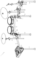
次に、図2から図4を参照して、クランプ10の構成について説明する。図2は、湾曲パイプ3及び支持パイプ4を保持した状態におけるクランプ10の斜視図である。図3は、図2の矢印III方向から見たクランプ10の側面図である。図4(a)は、図3の矢印IV(a)方向におけるクランプ10の背面図であり、図4(b)は、第1部品30を開放した状態におけるクランプ10の背面図である。なお、図3では、湾曲パイプ3及び支持パイプ4の図示を省略している。   Next, the configuration of the clamp 10 will be described with reference to FIGS. FIG. 2 is a perspective view of the clamp 10 in a state where the bending pipe 3 and the support pipe 4 are held. FIG. 3 is a side view of the clamp 10 as seen from the direction of arrow III in FIG. 4A is a rear view of the clamp 10 in the direction of the arrow IV (a) in FIG. 3, and FIG. 4B is a rear view of the clamp 10 in a state where the first component 30 is opened. In FIG. 3, the curved pipe 3 and the support pipe 4 are not shown.

図2に示すように、クランプ10は、支持パイプ4に支持される楽器を演奏者の好みに応じて配置する際に支持パイプ4を湾曲パイプ3に連結させる部材であり、湾曲パイプ3を着脱可能に挟持固定する第1パイプ保持部11と、支持パイプ4を着脱可能に挟持固定する第2パイプ保持部12とを主に備えている。   As shown in FIG. 2, the clamp 10 is a member that connects the support pipe 4 to the curved pipe 3 when the musical instrument supported by the support pipe 4 is arranged according to the player's preference. It mainly includes a first pipe holding portion 11 that can be pinched and fixed, and a second pipe holding portion 12 that pinch and fix the support pipe 4 so as to be detachable.

図3に示すように、第1パイプ保持部11は、湾曲パイプ3を挟持固定する部位であり、略円筒状に形成されている。第1パイプ保持部11は、クランプ10の一部品である基部20の一側(図3左側)に形成される半円筒形状の第1固定部21と、クランプ10の一部品であると共に第1固定部21の一端側(図3上側)で回転可能に軸支される半円筒形状の第1部品30と、第1固定部21の他端側(図3下側)で回転可能に軸支される締付部材51とを主に備えている。   As shown in FIG. 3, the 1st pipe holding part 11 is a site | part which clamps and fixes the bending pipe 3, and is formed in the substantially cylindrical shape. The first pipe holding part 11 is a semi-cylindrical first fixing part 21 formed on one side (left side in FIG. 3) which is one part of the clamp 10, and one part of the clamp 10 and the first part. A semi-cylindrical first component 30 that is rotatably supported on one end side (upper side in FIG. 3) of the fixed portion 21 and a rotatably supported on the other end side (lower side in FIG. 3) of the first fixed portion 21. The fastening member 51 is mainly provided.

第1固定部21は、第1パイプ保持部11の一側を構成する部位であり、第1パイプ保持部11の軸心である軸O1方向(第1パイプ保持部11の一端側の開口中心と他端側の開口中心とを結ぶ線の方向)から視て円弧状に形成される第1当て面23と、他端側(図3下側)の外周面から突出する一対のボルト固定部24とを主に備えている。   The first fixing part 21 is a part constituting one side of the first pipe holding part 11, and is in the direction of the axis O <b> 1 that is the axis of the first pipe holding part 11 (opening center on one end side of the first pipe holding part 11). And a pair of bolt fixing portions projecting from the outer peripheral surface on the other end side (lower side in FIG. 3). 24 mainly.

第1当て面23は、第1パイプ保持部11の内周面の一側を構成すると共に湾曲パイプ3の一側を保持する部分であり、樹脂材料で構成される半円筒形状のパイプ用スリーブ61が内接されている。   The first contact surface 23 is a portion that constitutes one side of the inner peripheral surface of the first pipe holding portion 11 and also holds one side of the curved pipe 3, and is a semi-cylindrical pipe sleeve made of a resin material. 61 is inscribed.

第1部品30は、第1パイプ保持部11の他側を構成する半円筒形状の部品であり、軸O1方向から視て円弧状に形成される第1締付面31と、第1部品30の他端側(図3下側)の外周面から突出する第1ボルト挿入部32とを主に備えており、第1締付面31を第1固定部21の第1当て面23に対向させつつ、第1固定部21の一端側(図3上側)で回転可能に軸支されている。   The first part 30 is a semi-cylindrical part that forms the other side of the first pipe holding portion 11, and includes a first fastening surface 31 that is formed in an arc shape when viewed from the direction of the axis O <b> 1, and the first part 30. And a first bolt insertion portion 32 projecting from the outer peripheral surface on the other end side (lower side in FIG. 3), and the first fastening surface 31 faces the first contact surface 23 of the first fixing portion 21. In addition, the first fixed portion 21 is rotatably supported at one end side (the upper side in FIG. 3).

第1締付面31は、第1パイプ保持部11の内周面の他側を構成すると共に湾曲パイプ3の他側を保持する部分であり、樹脂材料で構成される半円筒形状のパイプ用スリーブ62が内接されている(図4(b)参照)。   The first fastening surface 31 is a portion that forms the other side of the inner peripheral surface of the first pipe holding portion 11 and holds the other side of the curved pipe 3, and is for a semi-cylindrical pipe made of a resin material. The sleeve 62 is inscribed (see FIG. 4B).

図4(a)又は図4(b)に示すように、一対の第1ボルト固定部24は、軸O1方向に沿って所定の間隔を隔てて並設されており、一対の第1ボルト固定部24の間には後述するボルト軸部51bが挿設されている。また、一対の第1ボルト固定部24及びボルト軸部51bには、軸O1に沿って回転軸が軸通されており、ボルト軸部51bが一対のボルト固定部24により回転可能に軸支されている。   As shown in FIG. 4A or 4B, the pair of first bolt fixing portions 24 are arranged in parallel along the axis O1 direction at a predetermined interval, and the pair of first bolt fixing portions A bolt shaft portion 51b, which will be described later, is inserted between the portions 24. The pair of first bolt fixing portions 24 and the bolt shaft portions 51b are provided with shafts of rotation along the axis O1, and the bolt shaft portions 51b are rotatably supported by the pair of bolt fixing portions 24. ing.

第1ボルト挿入部32は、側面方向(図4(a)左右方向)から視て略U字状に形成されており、中央部分には、外側(図4(a)手前側)に向けて開口すると共に後述するおねじ部51aが挿入可能な溝が形成されている。   The first bolt insertion portion 32 is formed in a substantially U shape when viewed from the side surface direction (FIG. 4A, left-right direction), and toward the outer side (front side in FIG. 4A) at the center portion. A groove is formed that is open and into which a male screw 51a described later can be inserted.

締付部材51は、第1当て面23と第1締付面31との間に挟まれた湾曲パイプ3を挟持固定するために第1部品30を第1固定部21側へ押圧するための部材であり、外周面におねじが螺刻された棒状のおねじ部51aと、おねじ部51aの一端側に固着されると共に第1ボルト固定部24に回転可能に軸支されるボルト軸部51bと、内周面におねじ部51aに螺合可能なめねじが螺刻されためねじ孔51c1が貫通形成されるハンドルナット51cと、ボルト軸部51b及びハンドルナット51cの間に配設されると共におねじ部51aに緩装される円環状の座金51dとを主に備えている。また、ボルト軸部51bと座金51dとの間には、コイルスプリング(図示せず)がおねじ部51aに外装されており、座金51dは、コイルスプリングによりハンドルナット51c側に付勢されている。   The fastening member 51 is for pressing the first component 30 toward the first fixing portion 21 in order to sandwich and fix the curved pipe 3 sandwiched between the first contact surface 23 and the first fastening surface 31. A rod-shaped male screw portion 51a having a screw threaded on the outer peripheral surface thereof, and a bolt shaft fixed to one end of the male screw portion 51a and rotatably supported by the first bolt fixing portion 24 A portion 51b, a handle nut 51c in which a female screw that can be screwed into the screw portion 51a is threaded on the inner peripheral surface, and is formed between the bolt nut portion 51b and the handle nut 51c. And an annular washer 51d that is loosely mounted on the external thread 51a. A coil spring (not shown) is externally mounted on the external thread 51a between the bolt shaft 51b and the washer 51d, and the washer 51d is urged toward the handle nut 51c by the coil spring. .

ここで、第1パイプ保持部11による湾曲パイプ3の固定方法について説明する。図4(a)に示すように、湾曲パイプ3を第1パイプ保持部11で挟持固定するには、まず、めねじ孔51c1におねじ部51aを螺合させつつ、おねじ部51aを軸としてハンドルナット51cを回転させる。コイルスプリング(図示せず)によりハンドルナット51c側へ付勢される座金51dは、ハンドルナット51cによって、おねじ部51aの他端側から一端側(図4(a)左側から右側)へ押圧される。ハンドルナット51cを回転させ続けると、ハンドルナット51cに押圧される座金51dが第1ボルト挿入部32と当接する。さらにハンドルナット51cを回転させることで、第1ボルト挿入部32は、座金51dを介して押圧するハンドルナット51cの押圧力により、おねじ部51aの一端側(第1ボルト固定部24側)へ押圧される。   Here, a method for fixing the curved pipe 3 by the first pipe holding portion 11 will be described. As shown in FIG. 4A, in order to clamp and fix the curved pipe 3 with the first pipe holding portion 11, first, the screw portion 51a is screwed into the female screw hole 51c1, and the male screw portion 51a is pivoted. As a result, the handle nut 51c is rotated. A washer 51d urged to the handle nut 51c side by a coil spring (not shown) is pressed from the other end side of the male threaded portion 51a to one end side (FIG. 4 (a) from the left side to the right side) by the handle nut 51c. The When the handle nut 51c is continuously rotated, the washer 51d pressed against the handle nut 51c comes into contact with the first bolt insertion portion 32. Further, by rotating the handle nut 51c, the first bolt insertion portion 32 is moved to one end side (the first bolt fixing portion 24 side) of the external thread portion 51a by the pressing force of the handle nut 51c pressed through the washer 51d. Pressed.

このように、ハンドルナット51cをおねじ部51aに螺入させる際の押圧力を利用して第1部品30を第1固定部21側へ押圧することにより、湾曲パイプ3を第1固定部21と第1部品30の間で挟持固定することができる。   In this way, the first pipe 30 is pressed toward the first fixing portion 21 by using the pressing force when the handle nut 51c is screwed into the male screw portion 51a. And the first part 30 can be clamped and fixed.

図4(a)に示すように、第2パイプ保持部12は、支持パイプ4を保持する部位であり、略円筒状に形成されている。第2パイプ保持部12は、クランプ10の一部品である基部20の他側(図4(a)右側)に形成される半円筒形状の第2固定部22と、クランプ10の一部品であると共に第2固定部22の一端側(図4(a)下側)で回転可能に軸支される半円筒形状の第2部品40と、第2固定部22の他端側(図4(a)上側)で回転可能に軸支される締付部材52とを主に備えている。   As shown in FIG. 4A, the second pipe holding portion 12 is a portion that holds the support pipe 4, and is formed in a substantially cylindrical shape. The second pipe holding portion 12 is a semi-cylindrical second fixing portion 22 formed on the other side (right side in FIG. 4A) that is a part of the clamp 10 and a part of the clamp 10. In addition, a semi-cylindrical second component 40 that is rotatably supported on one end side (the lower side in FIG. 4A) of the second fixing portion 22 and the other end side of the second fixing portion 22 (see FIG. 4A). ) And a fastening member 52 that is rotatably supported in the upper side).

第2固定部22は、基部20の他側に形成されると共に第2パイプ保持部12の一側を構成する半円筒形状の部位であり、第2パイプ保持部12の軸心である軸O2方向(第2パイプ保持部12の一端側の開口中心と他端側の開口中心とを結ぶ線の方向)から視て円弧状に形成される第2当て面25と、他端側(図4(a)上側)の外周面から第2固定部22の内周面まで連通すると共に第2締付面41方向(図4(a)右方向)に開口すると共にボルト軸部52bが挿入可能な溝状の第2ボルト固定部26(図3参照)とを主に備えている。第2当て面25は、第2パイプ保持部12の内周面の一側を構成すると共に支持パイプ4の一側を保持する部分である。   The second fixing portion 22 is a part of a semi-cylindrical shape that is formed on the other side of the base portion 20 and constitutes one side of the second pipe holding portion 12, and an axis O <b> 2 that is an axis of the second pipe holding portion 12. A second contact surface 25 formed in an arc shape when viewed from the direction (direction of a line connecting the opening center on one end side and the opening center on the other end side of the second pipe holding portion 12), and the other end side (FIG. 4). (A) It communicates from the outer peripheral surface of the upper side to the inner peripheral surface of the second fixing portion 22 and opens in the direction of the second fastening surface 41 (right direction in FIG. 4 (a)) and the bolt shaft portion 52b can be inserted. A groove-shaped second bolt fixing portion 26 (see FIG. 3) is mainly provided. The second abutment surface 25 is a portion that constitutes one side of the inner peripheral surface of the second pipe holding portion 12 and holds one side of the support pipe 4.

第2部品40は、第2パイプ保持部12の他側を構成する半円筒形状の部材であり、軸O2方向から視て円弧状に形成される第2締付面41と、他端側(図4(a)上側)の外周面から突出する第2ボルト挿入部42とを主に備えており、第2締付面41を第2固定部22の第2当て面25に対向させた状態で、第2固定部22の一端側で回転可能に軸支されている。第2締付面41は、第2パイプ保持部12の内周面の他側(図4(a)右側)を構成すると共に支持パイプ4の他側を保持する部分である。   The second component 40 is a semi-cylindrical member that forms the other side of the second pipe holding portion 12, and includes a second fastening surface 41 formed in an arc shape when viewed from the direction of the axis O2, and the other end side ( 4 (a) upper side) mainly including a second bolt insertion portion 42 protruding from the outer peripheral surface, with the second fastening surface 41 opposed to the second contact surface 25 of the second fixing portion 22. Thus, the second fixed portion 22 is rotatably supported on one end side. The second fastening surface 41 is a portion that constitutes the other side (the right side in FIG. 4A) of the inner peripheral surface of the second pipe holding portion 12 and holds the other side of the support pipe 4.

図3に示すように、第2ボルト固定部26は、軸O2方向に沿った断面視(図3のA−A線における断面視)において略コ字状に凹設される溝状の部分であり、ボルト軸部52bが挿設されている。また、第2ボルト固定部26及びボルト軸部52bには、軸O2方向に沿って回転軸が軸通されており、ボルト軸部52bが第2ボルト固定部26に回転可能に軸支されている。   As shown in FIG. 3, the second bolt fixing portion 26 is a groove-like portion that is recessed in a substantially U shape in a cross-sectional view along the axis O <b> 2 direction (a cross-sectional view taken along the line AA in FIG. 3). Yes, a bolt shaft portion 52b is inserted. The second bolt fixing portion 26 and the bolt shaft portion 52b have a rotation shaft passing along the direction of the axis O2, and the bolt shaft portion 52b is rotatably supported by the second bolt fixing portion 26. Yes.

第2ボルト挿入部42は、正面方向(図3左右方向)から視て略U字状に形成されており(図2参照)、中央部分には、外側(図3手前側)に向けて開口すると共におねじ部52aが挿入可能な溝が形成されている。   The second bolt insertion portion 42 is formed in a substantially U shape when viewed from the front direction (left and right direction in FIG. 3) (see FIG. 2), and is open toward the outside (front side in FIG. 3) in the central portion. In addition, a groove into which the external thread portion 52a can be inserted is formed.

締付部材52は、第2当て面25と第2締付面41との間に挟まれた支持パイプ4を挟持固定するために第2部品40を第2固定部22側へ押圧するための部材であり、外周面におねじが螺刻された棒状のおねじ部52aと、おねじ部52aの一端側に固着されると共に第2ボルト固定部26に回転可能に軸支されるボルト軸部52bと、内周面におねじ部52aが螺合可能なめねじが螺刻されためねじ孔52c1が貫通形成されるハンドルナット52cと、ボルト軸部52b及びハンドルナット52cの間に配設されると共におねじ部52aに緩装される円環状の座金52dとを備えている。また、ボルト軸部52bと座金52dとの間には、コイルスプリング(図示せず)がおねじ部52aに外装されており、座金52dは、コイルスプリングによりハンドルナット52c側に付勢されている。なお、第2パイプ保持部12による支持パイプ4の固定方法は、上記した締付部材51と同様である。   The fastening member 52 is used for pressing the second component 40 toward the second fixing portion 22 in order to sandwich and fix the support pipe 4 sandwiched between the second contact surface 25 and the second fastening surface 41. A rod-shaped male threaded portion 52a having a screw threaded on the outer peripheral surface thereof, and a bolt shaft fixed to one end of the male threaded portion 52a and rotatably supported by the second bolt fixing portion 26 The portion 52b is disposed between a handle nut 52c in which a threaded hole 52c1 is formed so as to be screwed into the inner peripheral surface of a threaded screw 52a, and the bolt shaft portion 52b and the handle nut 52c. And an annular washer 52d loosely mounted on the male threaded portion 52a. A coil spring (not shown) is externally mounted on the external thread portion 52a between the bolt shaft portion 52b and the washer 52d, and the washer 52d is urged toward the handle nut 52c by the coil spring. . The method of fixing the support pipe 4 by the second pipe holding part 12 is the same as that of the tightening member 51 described above.

なお、基部20、第1部品30及び第2部品40は、アルミダイキャスト等の金属で構成されている。これにより、樹脂材料で構成される場合と比べて耐久性を向上させることができると共に、湾曲パイプ3及び支持パイプ4を保持する際の圧力を確保することができる。   In addition, the base 20, the 1st component 30, and the 2nd component 40 are comprised with metals, such as aluminum die-casting. Thereby, durability can be improved compared with the case where it consists of a resin material, and the pressure at the time of holding the curved pipe 3 and the support pipe 4 can be ensured.

次に、図5を参照して、パイプ用スリーブ62の構成について説明する。図5(a)は、パイプ用スリーブ62の側面図であり、図5(b)は、図5(a)の矢印Vb方向から視たパイプ用スリーブ62の背面図である。なお、パイプ用スリーブ61とパイプ用スリーブ62とは同一形状であるため、パイプ用スリーブ62についてのみ説明する。   Next, the configuration of the pipe sleeve 62 will be described with reference to FIG. 5A is a side view of the pipe sleeve 62, and FIG. 5B is a rear view of the pipe sleeve 62 viewed from the direction of the arrow Vb in FIG. 5A. Since the pipe sleeve 61 and the pipe sleeve 62 have the same shape, only the pipe sleeve 62 will be described.

図5(a)又は図5(b)に示すように、パイプ用スリーブ62は、ガラス繊維を含有する樹脂材料で構成される半円筒形状の部材であり、第1当て面23及び第1締付面31の形状に適合するように形成されている(図6(c)参照)。   As shown in FIG. 5 (a) or FIG. 5 (b), the pipe sleeve 62 is a semi-cylindrical member made of a resin material containing glass fiber, and includes the first contact surface 23 and the first fastening member. It is formed so as to conform to the shape of the abutting surface 31 (see FIG. 6C).

また、パイプ用スリーブ62は、外周面(図5(a)右側)の略中央部分から突出する圧入凸部62aを備え、圧入凸部62aは、外壁面に複数の山部が凸設されている。第1締付面31に形成される圧入孔部31c(図6(a)参照)に圧入凸部62aを圧入することにより、圧入された圧入凸部62aに形成される複数の山部が圧入孔部31cの内壁面を押圧するので、圧入凸部62aを圧入孔部31cへより確実に嵌合させることができ、パイプ用スリーブ62を第1締付面31に確実に装着することができる。   The pipe sleeve 62 includes a press-fit convex portion 62a that protrudes from a substantially central portion of the outer peripheral surface (right side in FIG. 5A), and the press-fit convex portion 62a has a plurality of peaks protruding from the outer wall surface. Yes. By press-fitting the press-fitting convex portion 62a into the press-fitting hole portion 31c (see FIG. 6A) formed on the first tightening surface 31, a plurality of peaks formed on the press-fitted convex portion 62a are press-fitted. Since the inner wall surface of the hole portion 31c is pressed, the press-fit convex portion 62a can be more reliably fitted into the press-fit hole portion 31c, and the pipe sleeve 62 can be reliably attached to the first tightening surface 31. .

なお、パイプ用スリーブ61,62に使用される樹脂材料は、ヤング率が0.5GPa以上10GPa未満であることが望ましい。ヤング率を10GPa未満に設定することで、クランプ10に湾曲パイプ3を挟持固定する際に、パイプ用スリーブ61,62によって湾曲パイプ3が損傷することを防止できる。また、湾曲形状の湾曲パイプ3の形状に合わせてパイプ用スリーブ61,62を変形させやすくすることができるので、その分、パイプ用スリーブ61,62の内周面と湾曲パイプ3との接触面積を大きく確保することができる。
The resin material used for the pipe sleeves 61 and 62 preferably has a Young's modulus of 0.5 GPa or more and less than 10 GPa. By setting the Young's modulus to less than 10 GPa, the curved pipe 3 can be prevented from being damaged by the pipe sleeves 61 and 62 when the curved pipe 3 is clamped and fixed to the clamp 10. In addition, since the pipe sleeves 61 and 62 can be easily deformed in accordance with the shape of the curved pipe 3, the contact area between the inner peripheral surfaces of the pipe sleeves 61 and 62 and the curved pipe 3 is increased accordingly. Can be secured greatly.

さらに、ヤング率を0.5GPa以上に設定することで、湾曲パイプ3を挟持固定する際の圧力がパイプ用スリーブ61,62に吸収されることを抑制して、湾曲パイプ3に圧力を確実に伝達することができる。また、ヤング率が小さいゴム等に比べ、圧縮に対する耐歪性を高くすることができるので、クランプ10により湾曲パイプ3を固定する際に、湾曲パイプ3と第1当て面23又は第1締付面31との間でパイプ用スリーブ61,62が反復継続して圧縮されても、パイプ用スリーブ61,62の永久圧縮歪を抑制することができると共に、パイプ用スリーブ61,62の耐久性を向上させることができる。   Furthermore, by setting the Young's modulus to 0.5 GPa or more, the pressure at the time of clamping and fixing the curved pipe 3 is suppressed from being absorbed by the pipe sleeves 61 and 62, and the pressure is reliably applied to the curved pipe 3. Can communicate. In addition, since the strain resistance against compression can be increased as compared with rubber having a low Young's modulus, when the curved pipe 3 is fixed by the clamp 10, the curved pipe 3 and the first contact surface 23 or the first tightening are used. Even if the pipe sleeves 61 and 62 are repeatedly compressed with respect to the surface 31, permanent compression distortion of the pipe sleeves 61 and 62 can be suppressed, and the durability of the pipe sleeves 61 and 62 can be improved. Can be improved.

ここで、パイプ用スリーブ61,62に使用される樹脂材料としては、例えば、ポリアミド、ポリプロピレン、ABS樹脂、ポリカーボネート等が挙げられる。なお、本実施の形態におけるパイプ用スリーブ61,62はガラス繊維を複合させたポリアミドを使用している。ガラス繊維を複合させることで、船等による輸送時においてパイプ用スリーブ61,62が高温下に置かれる場合であっても、パイプ用スリーブ61,62が高温により熱変形することを抑制できる。   Here, examples of the resin material used for the pipe sleeves 61 and 62 include polyamide, polypropylene, ABS resin, and polycarbonate. The pipe sleeves 61 and 62 in the present embodiment are made of polyamide in which glass fibers are combined. By combining the glass fibers, it is possible to suppress the pipe sleeves 61 and 62 from being thermally deformed due to the high temperature even when the pipe sleeves 61 and 62 are placed at a high temperature during transportation by a ship or the like.

次に、図6を参照して、第1締付面31の詳細構成について説明する。図6(a)は、第1部品30の裏面図であり、図6(b)は、図6(a)のVIb−VIb線における第1部品30の断面図であり、図6(c)は、第1締付面31にパイプ用スリーブ62を装着した状態における第1部品30の裏面図であり、図6(d)は、図6(c)のVId−VId線における第1部品30の断面図である。   Next, the detailed configuration of the first fastening surface 31 will be described with reference to FIG. 6A is a back view of the first component 30, and FIG. 6B is a cross-sectional view of the first component 30 taken along the line VIb-VIb of FIG. 6A. FIG. 6B is a rear view of the first component 30 in a state in which the pipe sleeve 62 is attached to the first fastening surface 31, and FIG. 6D is a diagram illustrating the first component 30 taken along the line VId-VId in FIG. FIG.

図6(a)又は図6(b)に示すように、第1締付面31は、軸O1方向(図6(a)左右方向)の両端に、周方向へ連設して凸設される一対の凸設壁31aを備えている。   As shown in FIG. 6 (a) or FIG. 6 (b), the first fastening surface 31 is provided in a projecting manner in the circumferential direction at both ends in the direction of the axis O1 (the left-right direction in FIG. 6 (a)). A pair of protruding walls 31a.

なお、請求項2記載の「パイプ保持部の両側の開口」とは、軸O1方向(図6(a)左右方向)における第1パイプ保持部11(図4(b)参照)の両端を示している。   Note that “openings on both sides of the pipe holding portion” according to claim 2 indicate both ends of the first pipe holding portion 11 (see FIG. 4B) in the direction of the axis O1 (FIG. 6A left-right direction). ing.

また、第1締付面31は、第1締付面31の略中央部分に、第1締付面31からの凹設深さ(第1締付面31から第1部品30の外周面側への深さ)が一定に形成され、軸O1方向に沿った断面視(図6(a)及び図6(b)のB−B線における断面視)が略コ字状である凹部31bを備えている。さらに、凹部31bの略中央部分には、第1部品30の外周面側まで貫通すると共に、パイプ用スリーブ62の圧入凸部62aが嵌合可能な圧入孔部31cが形成されている。   Further, the first fastening surface 31 is provided at a substantially central portion of the first fastening surface 31 with a recessed depth from the first fastening surface 31 (from the first fastening surface 31 to the outer peripheral surface side of the first component 30). A recess 31b having a substantially U-shaped cross-sectional view (cross-sectional view taken along line BB in FIGS. 6A and 6B) along the direction of the axis O1. I have. Furthermore, a press-fitting hole 31c that penetrates to the outer peripheral surface side of the first component 30 and can be fitted with the press-fitting convex part 62a of the pipe sleeve 62 is formed at a substantially central portion of the concave part 31b.

ここで、本実施の形態では、凹部31bが、図6(a)における正面視において略矩形状に形成されているが、これに限られるものではなく、例えば、略菱形状または楕円形状に形成されていてもよい。   Here, in the present embodiment, the recess 31b is formed in a substantially rectangular shape when viewed from the front in FIG. 6A. However, the present invention is not limited to this. For example, the recess 31b is formed in a substantially rhomboid or elliptical shape. May be.

図6(c)又は図6(d)に示すように、パイプ用スリーブ62の外周面と第1締付面31とを対向させ、圧入凸部62aを圧入孔部31cに圧入することにより、パイプ用スリーブ62は、第1締付面31に装着される。また、圧入凸部62aが圧入孔部31cに圧入されることにより、パイプ用スリーブ62が軸O1方向(図6(c)左右方向)、及び、第1締付面31の周方向(図6(d)参照)へ移動することを規制できる。
As shown in FIG. 6C or 6D, the outer peripheral surface of the pipe sleeve 62 and the first fastening surface 31 are opposed to each other, and the press-fitting convex portion 62a is press-fitted into the press-fitting hole portion 31c. The pipe sleeve 62 is attached to the first fastening surface 31. Further, when the press-fitting convex portion 62a is press-fitted into the press-fitting hole portion 31c, the pipe sleeve 62 moves in the direction of the axis O1 (FIG. 6 (c) left-right direction) and the circumferential direction of the first tightening surface 31 (FIG. 6). (D) can be restricted.

パイプ用スリーブ62は、外周面の曲面形状が第1締付面31の曲面形状と一致するように形成されているので、パイプ用スリーブ62を第1締付面31に装着することにより、パイプ用スリーブ62の外周面と第1締付面31とを当接させることができる。また、第1締付面31とパイプ用スリーブ62との間には、第1締付面31に形成される凹部31b及び凹部31bと対向するパイプ用スリーブ62の外周面によって包囲される一定の空間Sが形成される。   Since the pipe sleeve 62 is formed so that the curved surface shape of the outer peripheral surface matches the curved surface shape of the first fastening surface 31, the pipe sleeve 62 is attached to the first fastening surface 31, so that The outer circumferential surface of the sleeve 62 and the first fastening surface 31 can be brought into contact with each other. In addition, between the first fastening surface 31 and the pipe sleeve 62, there is a fixed portion surrounded by the recess 31b formed in the first fastening surface 31 and the outer peripheral surface of the pipe sleeve 62 facing the recess 31b. A space S is formed.

なお、第1締付面31のうち、凹部31bが占める割合が大きいほど、パイプ用スリーブ62の外周面と第1締付面31との接触面積が小さくなる。そのため、例えば、凹部31bが、第1締付面31の周方向(図6(a)上下方向、図6(d)参照)の全体に形成されている場合、その分、パイプ用スリーブ62の外周面と第1締付面31との接触面積が小さくなる。従って、第1パイプ保持部11により湾曲パイプ3を挟持固定する際の圧力(締付部材51の螺入により、第1部品30を第1固定部21側へ押圧する力)を湾曲パイプ3へ十分に伝達させることができない。   In addition, the contact area of the outer peripheral surface of the sleeve 62 for pipes and the 1st clamping surface 31 becomes small, so that the ratio for which the recessed part 31b accounts among the 1st clamping surfaces 31 is large. Therefore, for example, when the concave portion 31b is formed in the entire circumferential direction of the first fastening surface 31 (see FIG. 6A, vertical direction, see FIG. 6D), the pipe sleeve 62 is correspondingly increased. The contact area between the outer peripheral surface and the first fastening surface 31 is reduced. Therefore, the pressure at the time of clamping and fixing the curved pipe 3 by the first pipe holding portion 11 (force to press the first component 30 toward the first fixing portion 21 by the screwing of the fastening member 51) is applied to the curved pipe 3. It cannot be fully communicated.

これに対し、本実施の形態では、凹部31bが第1締付面31の略中央部分に形成され、軸O1方向(図6(a)左右方向)における凹部31bを挟んだ両側、および、第1締付面31の周方向における凹部31bを挟んだ両側で、パイプ用スリーブ62の外周面と第1締付面31とを互いに当接させることができる。よって、パイプ用スリーブ62の外周面と第1締付面31との接触面積を広く確保することができるので、第1パイプ保持部11により湾曲パイプ3を挟持固定する際の圧力を、パイプ用スリーブ62を介して湾曲パイプ3へ確実に伝達させることができる。   On the other hand, in the present embodiment, the recess 31b is formed in a substantially central portion of the first tightening surface 31, and both sides sandwiching the recess 31b in the direction of the axis O1 (the left-right direction in FIG. 6A), and the first The outer peripheral surface of the pipe sleeve 62 and the first tightening surface 31 can be brought into contact with each other on both sides of the concave portion 31b in the circumferential direction of the first tightening surface 31. Therefore, a wide contact area between the outer peripheral surface of the pipe sleeve 62 and the first fastening surface 31 can be ensured, so that the pressure when the curved pipe 3 is clamped and fixed by the first pipe holding portion 11 is set to the pipe. It can be reliably transmitted to the bending pipe 3 through the sleeve 62.

さらに、パイプ用スリーブ62が第1締付面31に装着される際、パイプ用スリーブ62は、一対の凸設壁31aの間に配設される。このとき、凸設壁31aの先端がパイプ用スリーブ62の内周面よりも低く形成されているので、第1パイプ保持部11に湾曲パイプ3を固定する際に、パイプ用スリーブ62の内周面を湾曲パイプ3の外周面に当接させることで、凸設壁31aの先端と湾曲パイプ3とが当接することを防止できる。よって、第1パイプ保持部11により湾曲パイプ3を挟持固定する際の圧力により、湾曲パイプ3が凸設壁31aの先端に押圧されることで、湾曲パイプ3が変形、損傷することを回避できる。   Further, when the pipe sleeve 62 is attached to the first fastening surface 31, the pipe sleeve 62 is disposed between the pair of protruding walls 31a. At this time, since the tip of the protruding wall 31a is formed lower than the inner peripheral surface of the pipe sleeve 62, the inner periphery of the pipe sleeve 62 is fixed when the curved pipe 3 is fixed to the first pipe holding portion 11. By bringing the surface into contact with the outer peripheral surface of the curved pipe 3, it is possible to prevent the tip of the protruding wall 31a from coming into contact with the curved pipe 3. Therefore, the bending pipe 3 can be prevented from being deformed or damaged by being pressed against the tip of the protruding wall 31a by the pressure when the bending pipe 3 is clamped and fixed by the first pipe holding portion 11. .

また、パイプ用スリーブ62が装着されていない場合、クランプ10に湾曲パイプ3を緩挿させた状態でクランプ10を湾曲パイプ3に沿って摺動させると、金属製の湾曲パイプ3と金属製の第1締付面31との接触面に大きな摩擦力が生じる。即ち、湾曲パイプ3及び第1締付面31が金属で構成されているので、湾曲パイプ3及び第1締付面31が互いに接触することにより、湾曲パイプ3及び第1締付面31の表面に傷がつく。これにより、湾曲パイプ3及び第1締付面31の表面が互いに噛みこみやすくなり、湾曲パイプ3を摺動させる際の摩擦力が増加するため、湾曲パイプ3を摺動させる際に強い力を加える必要があるだけでなく、摺動させることに伴って騒音が発生する。   In addition, when the pipe sleeve 62 is not attached, when the clamp 10 is slid along the curved pipe 3 while the curved pipe 3 is loosely inserted into the clamp 10, the metal curved pipe 3 and the metal A large frictional force is generated on the contact surface with the first tightening surface 31. That is, since the curved pipe 3 and the first fastening surface 31 are made of metal, the curved pipe 3 and the first fastening surface 31 come into contact with each other, so that the surfaces of the curved pipe 3 and the first fastening surface 31 are brought into contact with each other. Will be scratched. Thereby, the curved pipe 3 and the surface of the first fastening surface 31 are easily engaged with each other, and the frictional force when the curved pipe 3 is slid increases, so that a strong force is applied when the curved pipe 3 is slid. Not only does it need to be added, but it also generates noise as it slides.

これに対し、本実施の形態では、樹脂材料で構成されるパイプ用スリーブ62が湾曲パイプ3と第1締付面31との間に介在されているので、クランプ10に湾曲パイプ3を緩挿させた状態で湾曲パイプ3に沿ってクランプ10を摺動させる際に、湾曲パイプ3及び第1締付面31の表面に傷がつくことを防止できる。よって、湾曲パイプ3を摺動させる際の摩擦力を低減させることができるので、クランプ10を円滑に摺動させることができると共に、クランプ10の摺動による騒音の発生および湾曲パイプ3の損傷を抑制することができる。   On the other hand, in the present embodiment, since the pipe sleeve 62 made of a resin material is interposed between the curved pipe 3 and the first fastening surface 31, the curved pipe 3 is loosely inserted into the clamp 10. When the clamp 10 is slid along the curved pipe 3 in the state of being made, it is possible to prevent the curved pipe 3 and the first fastening surface 31 from being damaged. Therefore, since the frictional force at the time of sliding the bending pipe 3 can be reduced, the clamp 10 can be smoothly slid, noise generated by the sliding of the clamp 10 and damage to the bending pipe 3 can be prevented. Can be suppressed.

ここで、本実施の形態では、パイプ用スリーブ62の外周面に形成される圧入凸部62aを圧入孔部31cに圧入することにより、パイプ用スリーブ62を第1締付面31に装着する場合を説明したが、必ずしもこれに限られるものではなく、外周面が平坦面状に形成されたパイプ用スリーブの外周面を第1締付面31に接着させてもよい。   Here, in the present embodiment, when the pipe sleeve 62 is attached to the first fastening surface 31 by press-fitting the press-fitting convex part 62a formed on the outer peripheral surface of the pipe sleeve 62 into the press-fitting hole part 31c. However, the present invention is not necessarily limited thereto, and the outer peripheral surface of the pipe sleeve having the outer peripheral surface formed into a flat surface may be bonded to the first fastening surface 31.

このとき、第1締付面31には、凸設壁31aが凸設されており、凸設壁31aの先端は、第1締付面31に当接されているパイプ用スリーブの外周面よりも高い位置にあるので、第1締付面31とパイプ用スリーブの外周面との接着が解除された場合であっても、第1パイプ保持部11の開口に位置する凸設壁31aにより、パイプ用スリーブが第1パイプ保持部11の開口部分から脱落することを防止できる。   At this time, the first fastening surface 31 is provided with a protruding wall 31 a, and the tip of the protruding wall 31 a is from the outer peripheral surface of the pipe sleeve that is in contact with the first fastening surface 31. Is also at a high position, so even if the adhesion between the first fastening surface 31 and the outer peripheral surface of the pipe sleeve is released, the protruding wall 31a located at the opening of the first pipe holding portion 11 The pipe sleeve can be prevented from falling off from the opening of the first pipe holding portion 11.

なお、第1当て面23は、凸設壁23aと、凹部23bと、圧入孔部23cとを備えており、それらの作用は上記した第1締付面31と同様なので、それらの説明を省略する。また、第2当て面25及び第2締付面41は、凹部25b,41bを備えており、凹部25b,41bは、第1締付面31に形成される凹部31bと同様に構成されている。   The first contact surface 23 includes a protruding wall 23a, a recessed portion 23b, and a press-fit hole portion 23c, and the operation thereof is the same as that of the first tightening surface 31 described above, and thus description thereof is omitted. To do. The second contact surface 25 and the second fastening surface 41 are provided with recesses 25 b and 41 b, and the recesses 25 b and 41 b are configured in the same manner as the recess 31 b formed on the first fastening surface 31. .

次に、図7を参照して、クランプ10による湾曲パイプ3の固定方法について説明する。図7は、図3のVII−VII線における湾曲パイプ3を保持した状態のクランプ10の断面図である。   Next, a method for fixing the curved pipe 3 by the clamp 10 will be described with reference to FIG. FIG. 7 is a cross-sectional view of the clamp 10 in a state where the bending pipe 3 is held along the line VII-VII in FIG.

クランプ10により湾曲パイプ3を保持する際、まず、第1当て面23に形成される凹部23b又は第1締付面31に形成される凹部31bのいずれか一方へ湾曲パイプ3の凸曲部分を向けた状態で、湾曲パイプ3を第1固定部21と第1部品30との間に配置する。なお、本実施の形態では、第1締付面31に形成される凹部31bへ湾曲パイプ3の凸曲部分を向けて配置する場合について説明する。   When the curved pipe 3 is held by the clamp 10, first, the convex curved portion of the curved pipe 3 is placed on either the concave portion 23 b formed on the first contact surface 23 or the concave portion 31 b formed on the first fastening surface 31. The bent pipe 3 is disposed between the first fixing portion 21 and the first component 30 in the state of being directed. In the present embodiment, a description will be given of a case where the curved portion of the curved pipe 3 is directed toward the concave portion 31b formed in the first fastening surface 31.

次に、第1固定部21の第1当て面23と第1部品30の第1締付面31とにより、湾曲パイプ3を挟持しつつ、第1固定部21のボルト固定部24に回転可能に軸支される締付部材51を回転させて、おねじ部51aをボルト挿入部32に挿入させる(図4(a)及び図4(b)参照)。   Next, it is possible to rotate to the bolt fixing portion 24 of the first fixing portion 21 while holding the curved pipe 3 by the first contact surface 23 of the first fixing portion 21 and the first fastening surface 31 of the first component 30. The fastening member 51 pivotally supported by the shaft is rotated, and the external thread portion 51a is inserted into the bolt insertion portion 32 (see FIGS. 4A and 4B).

続いて、上記のように、ハンドルナット51cのめねじ孔51c1におねじ部51aを螺合させて、ハンドルナット51c及び座金51dを螺入方向(図7右方向)へ移動させる。これにより、第1部品30に形成される第1ボルト挿入部32が、座金51dを介してハンドルナット51cに押圧されることで、第1部品30が第1固定部21側へ押圧される。   Subsequently, as described above, the screw portion 51a is screwed into the female screw hole 51c1 of the handle nut 51c, and the handle nut 51c and the washer 51d are moved in the screwing direction (right direction in FIG. 7). Thereby, the 1st bolt insertion part 32 formed in the 1st component 30 is pressed by the handle nut 51c via the washer 51d, and the 1st component 30 is pressed to the 1st fixing | fixed part 21 side.

第1部品30が第1固定部21側へ押圧されると、第1当て面23及び第1締付面31に装着される一対のパイプ用スリーブ61,62が湾曲パイプ3の外周面と当接する。このとき、湾曲パイプ3の凸曲側の外周面は、第1締付面31に装着されるパイプ用スリーブ62の湾曲パイプ3の長手方向における中央部分でパイプ用スリーブ62の内周面側(図7右側)に当接され、湾曲パイプ3の凹曲側の外周面は、第1当て面23に装着されるパイプ用スリーブ61の湾曲パイプ3の長手方向における両端側(図7上下方向側)部分でパイプ用スリーブ61の内周面側(図7左側)に当接されている。   When the first component 30 is pressed toward the first fixing portion 21, the pair of pipe sleeves 61 and 62 attached to the first contact surface 23 and the first fastening surface 31 are brought into contact with the outer peripheral surface of the curved pipe 3. Touch. At this time, the outer peripheral surface of the curved pipe 3 on the convex curved side is the inner peripheral surface side of the pipe sleeve 62 at the central portion in the longitudinal direction of the curved pipe 3 of the pipe sleeve 62 attached to the first fastening surface 31 ( The concave outer peripheral surface of the curved pipe 3 is in contact with the curved pipe 3 attached to the first contact surface 23 at both ends in the longitudinal direction of the curved pipe 3 (the vertical direction side in FIG. 7). ) Portion is in contact with the inner peripheral surface side (left side in FIG. 7) of the pipe sleeve 61.

湾曲パイプ3の凹曲側の外周面と当接するパイプ用スリーブ61の一部分(湾曲パイプ3の長手方向における両端側部分の内周面)は、パイプ用スリーブ61の外周面側が第1当て面23と当接しているので、第1部品30を第1固定部21に押圧するほど、その分、第1当て面23からの押圧力がパイプ用スリーブ61を介して湾曲パイプ3に伝達される。よって、湾曲パイプ3を第1締付面31側(図7左側)へ押圧しようとする力を強く付与することができる。
A part of the pipe sleeve 61 (inner peripheral surface of both end portions in the longitudinal direction of the curved pipe 3) that abuts on the concave outer peripheral surface of the curved pipe 3 is the first contact surface 23 on the outer peripheral surface side of the pipe sleeve 61. As the first part 30 is pressed against the first fixing portion 21, the pressing force from the first contact surface 23 is transmitted to the curved pipe 3 via the pipe sleeve 61. Therefore, it is possible to strongly apply a force for pressing the bending pipe 3 toward the first fastening surface 31 (left side in FIG. 7).

これに対し、第1締付面31には凹部31bが形成されているので、湾曲パイプ3の凸曲側の外周面と当接するパイプ用スリーブ62の一部分(湾曲パイプ3の長手方向における中央部分)は、第1締付面31に当接させることができないので、第1締付面31からの押圧力を伝達することができない。   On the other hand, since the concave portion 31b is formed in the first tightening surface 31, a part of the pipe sleeve 62 that contacts the outer peripheral surface of the curved pipe 3 on the convex side (the central portion in the longitudinal direction of the curved pipe 3). ) Cannot be brought into contact with the first tightening surface 31, and cannot transmit the pressing force from the first tightening surface 31.

よって、第1部品30を第1固定部21に押圧させることにより、パイプ用スリーブ62のうち、外周面が凹部31bと対向する部分は、湾曲パイプ3の凸曲部分に押圧され、空間Sの内部へ押しこまれる。これにより、パイプ用スリーブ62が、変形させにくいガラス繊維を含有する樹脂材料により構成されている場合でも、湾曲パイプ3の凸曲形状に合わせてパイプ用スリーブ62を変形させやすくすることができるので、パイプ用スリーブ62と湾曲パイプ3との接触面積を広く確保することができる。   Therefore, by pressing the first component 30 against the first fixing portion 21, a portion of the pipe sleeve 62 whose outer peripheral surface faces the concave portion 31 b is pressed by the convex portion of the curved pipe 3, and the space S It is pushed inside. Thereby, even when the pipe sleeve 62 is made of a resin material containing glass fiber that is difficult to deform, the pipe sleeve 62 can be easily deformed in accordance with the convex shape of the curved pipe 3. A wide contact area between the pipe sleeve 62 and the curved pipe 3 can be ensured.

また、パイプ用スリーブ62が湾曲パイプ3の凸曲部分の形状に合わせて湾曲する際、パイプ用スリーブ62の外周面は、軸O1方向(図3参照)における凹部31bの両側(図7上側および下側)で第1締付面31と当接している。よって、パイプ用スリーブ62の外周面と第1締付面31との当接面(軸O1方向における凹部31bの両側)から、第1部品30を第1固定部21に押圧させることによる押圧力が伝達されるので、湾曲パイプ3を第1固定部21側(図7右側)へ押圧することができる。   Further, when the pipe sleeve 62 is bent in accordance with the shape of the convex portion of the curved pipe 3, the outer peripheral surface of the pipe sleeve 62 is on both sides of the concave portion 31b in the direction of the axis O1 (see FIG. 3) The lower side is in contact with the first fastening surface 31. Therefore, the pressing force by pressing the first component 30 against the first fixing portion 21 from the contact surface between the outer peripheral surface of the pipe sleeve 62 and the first fastening surface 31 (on both sides of the recess 31b in the direction of the axis O1). Is transmitted, the curved pipe 3 can be pressed toward the first fixed portion 21 (the right side in FIG. 7).

このようにして、第1部品30を第1固定部21側へ押圧する押圧力が、パイプ用スリーブ61,62を介して湾曲パイプ3へ伝達されるので、湾曲パイプ3を第1パイプ保持部11に挟持固定することができる。また、樹脂材料で構成されるパイプ用スリーブ61,62を介して湾曲パイプ3を保持するので、湾曲パイプ3に第1当て面23及び第1締付面31を直に当接させて保持するよりも、湾曲パイプ3との接触面積を大きく確保することができるので、その分、湾曲パイプ3を挟持固定するための圧力を湾曲パイプ3へ効率よく伝達することができ、確実に湾曲パイプ3を固定することができる。   In this way, the pressing force that presses the first component 30 toward the first fixing portion 21 is transmitted to the bending pipe 3 via the pipe sleeves 61 and 62, so that the bending pipe 3 is connected to the first pipe holding portion. 11 can be clamped and fixed. Further, since the curved pipe 3 is held via the pipe sleeves 61 and 62 made of a resin material, the first contact surface 23 and the first fastening surface 31 are held in direct contact with the curved pipe 3. As a result, a larger contact area with the curved pipe 3 can be ensured, and accordingly, the pressure for clamping and fixing the curved pipe 3 can be efficiently transmitted to the curved pipe 3, and the curved pipe 3 can be reliably transmitted. Can be fixed.

ここで、締付部材51は、ハンドルナット51cがおねじ部51aに螺入されることにより、座金51dを介して第1ボルト挿入部32を押圧することで、第1部品30が第1固定部21側へ押圧され、湾曲パイプ3を挟持固定する構成なので、湾曲パイプ3を挟持固定するための押圧力は、おねじ部51aの軸方向(図7左右方向)に沿った方向に付与される。   Here, in the tightening member 51, the first part 30 is fixed to the first part 30 by pressing the first bolt insertion part 32 via the washer 51d when the handle nut 51c is screwed into the male thread part 51a. Since the bending pipe 3 is sandwiched and fixed by being pressed toward the portion 21 side, the pressing force for sandwiching and fixing the bending pipe 3 is applied in a direction along the axial direction (left and right direction in FIG. 7) of the external thread 51a. The

これに対し、凹部23b,31bは、おねじ部51aの軸方向に沿った方向に向けて開口しているので、湾曲形状である湾曲パイプ3の凸曲部分を凹部23b,31bのいずれか一方に向けて配置することにより、ハンドルナット51cの螺入による押圧力を、湾曲パイプ3の凸曲部分がパイプ用スリーブ61,62を空間Sへ押しこむ押圧力として効率的に利用することができる。よって、パイプ用スリーブ61,62を変形させやすくすることができるので、その分、パイプ用スリーブ61,62と湾曲パイプ3との接触面積を広く確保して、湾曲パイプ3をより確実に挟持固定することができる。   On the other hand, since the recesses 23b and 31b are opened toward the direction along the axial direction of the external thread portion 51a, the convex portion of the curved pipe 3 having a curved shape is set to one of the recesses 23b and 31b. By being arranged toward the front, the pressing force generated by screwing the handle nut 51c can be efficiently used as the pressing force by which the convex portion of the bending pipe 3 pushes the pipe sleeves 61 and 62 into the space S. . Accordingly, the pipe sleeves 61 and 62 can be easily deformed, and accordingly, a large contact area between the pipe sleeves 61 and 62 and the curved pipe 3 is secured, and the curved pipe 3 is more securely clamped and fixed. can do.

さらに、圧入孔部23c,31cは、おねじ部51aの軸方向に沿った方向に向けて貫通形成されているので、湾曲形状である湾曲パイプ3の凸曲部分を凹部23b,31bのいずれか一方に向けて配置することにより、湾曲パイプ3を挟持固定するための押圧力を、湾曲パイプ3の凸曲部分が圧入凸部61a,62aを圧入孔部23c,31cへ押しこむ押圧力として効率的に利用できる。よって、パイプ用スリーブ61,62の第1当て面23及び第1締付面31への圧入固定が解除されることを防止できる。   Furthermore, since the press-fitting hole portions 23c and 31c are formed so as to penetrate in the direction along the axial direction of the male screw portion 51a, the curved portion of the curved pipe 3 having a curved shape is set to one of the concave portions 23b and 31b. By placing the curved pipe 3 toward one side, the pressing force for holding and fixing the bending pipe 3 is efficient as the pressing force by which the convex curved portion of the bending pipe 3 pushes the press-fitting convex portions 61a and 62a into the press-fitting hole portions 23c and 31c. Can be used. Therefore, it is possible to prevent the press-fitting and fixing of the pipe sleeves 61 and 62 to the first contact surface 23 and the first fastening surface 31 from being released.

また、凹部23b,31bが、軸O1方向において、第1当て面23又は第1締付面31の一端(例えば、図7上側)または両端(図7上側および下側)に形成される場合では、パイプ用スリーブ61,62の外周面と第1当て面23又は第1締付面31との当接面は1面のみである。   In the case where the recesses 23b and 31b are formed at one end (for example, the upper side in FIG. 7) or both ends (the upper side and the lower side in FIG. 7) of the first contact surface 23 or the first fastening surface 31 in the direction of the axis O1. The contact surfaces between the outer peripheral surfaces of the pipe sleeves 61 and 62 and the first contact surface 23 or the first fastening surface 31 are only one surface.

これに対し、本実施の形態では、凹部23b,31bが第1当て面23及び第1締付面31の略中央部分に形成されているので、軸O1方向において、パイプ用スリーブ61,62の外周面と第1当て面23又は第1締付面31とを、凹部23b,31bを挟んだ一側と両側(図7上側と下側)の2面で当接させることができる。よって、湾曲パイプ3を挟持固定するための押圧力をより確実に湾曲パイプ3へ伝達することができる。   On the other hand, in the present embodiment, since the recesses 23b and 31b are formed in the substantially central portions of the first contact surface 23 and the first fastening surface 31, the pipe sleeves 61 and 62 are arranged in the direction of the axis O1. The outer peripheral surface and the first contact surface 23 or the first fastening surface 31 can be brought into contact with each other on two surfaces, one side and both sides (the upper side and the lower side in FIG. 7) sandwiching the recesses 23b and 31b. Therefore, it is possible to more reliably transmit the pressing force for sandwiching and fixing the curved pipe 3 to the curved pipe 3.

また、第1当て面23又は第1締付面31のうちいずれか一方にのみ凹部23b,31bを備えているとすると、湾曲パイプ3の凸曲部分を凹部23b,31bに向けて挟持固定されているクランプ10を、湾曲パイプ3を軸として180度回転させようとする場合に、湾曲パイプ3の凸曲部分を凹部23b,31bに向けて配置することができなくなる。そのため、湾曲パイプ3の保持力を確保するには、使用しているクランプを凹部23b,31bの配置が異なるクランプと交換する必要がある。   Also, assuming that only one of the first contact surface 23 and the first tightening surface 31 is provided with the recesses 23b and 31b, the bent portion of the bending pipe 3 is clamped and fixed toward the recesses 23b and 31b. When the clamp 10 is to be rotated 180 degrees around the curved pipe 3, the convex curved portion of the curved pipe 3 cannot be disposed toward the concave portions 23b and 31b. Therefore, in order to secure the holding force of the bending pipe 3, it is necessary to replace the clamp being used with a clamp having a different arrangement of the recesses 23b and 31b.

これに対し、本実施の形態におけるクランプ10は、第1当て面23と第1締付面31との双方に凹部23b,31bが形成されているので、湾曲パイプ3の凸曲部分を凹部23b,31bに向けて挟持固定されているクランプ10を湾曲パイプ3を軸として半回転させようとする場合であっても、湾曲パイプ3の凸曲部分を凹部23b,31bに向けて配置することができるので、作業効率の向上を図ることができる。   On the other hand, in the clamp 10 according to the present embodiment, since the concave portions 23b and 31b are formed on both the first contact surface 23 and the first fastening surface 31, the convex portion of the curved pipe 3 is formed as the concave portion 23b. Even if the clamp 10 clamped and fixed toward the bending pipe 3 is to be half-rotated around the bending pipe 3, the protruding curved portion of the bending pipe 3 can be arranged toward the recesses 23b and 31b. As a result, work efficiency can be improved.

即ち、湾曲パイプ3の凸曲部分を凹部23bへ向けて配置する方法と、凹部31bが位置する方向へ向けて配置する方法との2つを選択することができる。よって、パイプを保持する際におけるクランプ10の向きに自由度をもたせることができる。   That is, it is possible to select two methods: a method of arranging the curved portion of the curved pipe 3 toward the concave portion 23b and a method of arranging the convex portion toward the concave portion 31b. Therefore, it is possible to give a degree of freedom to the direction of the clamp 10 when holding the pipe.

さらに、凹部23b,31bが、軸O1方向に沿った断面視(図6(a)及び図6(b)のB−B線における断面視)において円弧状に凹設されている場合、円弧状に形成される凹部23b,31bのRと保持すべき湾曲パイプ3のRとが一致しない場合には、パイプ用スリーブ61,62と湾曲パイプ3との接触面積を十分に確保できない。   Further, when the recesses 23b and 31b are recessed in an arc shape in a cross-sectional view along the direction of the axis O1 (a cross-sectional view in the line BB in FIGS. 6A and 6B), If the R of the recesses 23b and 31b formed in the plate does not match the R of the curved pipe 3 to be held, a sufficient contact area between the pipe sleeves 61 and 62 and the curved pipe 3 cannot be secured.

これに対し、本実施の形態では、凹部23b,31bが、第1当て面23又は第1締付面31からの凹設深さが一定であり、軸O1方向に沿った断面視が略コ字状に凹設されているので、空間Sの体積を大きく確保できるので、Rが一定の範囲内に設定される湾曲状の湾曲パイプ3を確実に保持することができる。   On the other hand, in the present embodiment, the recesses 23b and 31b have a constant recess depth from the first contact surface 23 or the first fastening surface 31, and the cross-sectional view along the direction of the axis O1 is substantially the same. Since it is recessed in the shape of a letter, a large volume of the space S can be secured, so that the curved curved pipe 3 in which R is set within a certain range can be reliably held.

また、上記のように、凸設壁23aの先端がパイプ用スリーブ61の内周面よりも低い位置にあるので、湾曲形状の湾曲パイプ3の凹曲側(図7右側)を保持する場合であっても、凸設壁23aの先端と湾曲パイプ3とが当接することを防止できる。よって、湾曲パイプ3を挟持固定する際にかかる圧力により湾曲パイプ3が凸設壁23aの先端に押圧されることで、湾曲パイプ3が変形、損傷することを抑制できる。特に、本実施の形態では、パイプ用スリーブ61,62が、ゴム等の樹脂と比べてヤング率の高いガラス繊維が複合された強化プラスチックで構成されており、湾曲パイプ3を挟持固定する際の圧力による耐歪性が高く確保されているので、パイプ用スリーブ61の内周面と凸設壁23aの先端との高さの差が小さくても、凸設壁23aの先端と湾曲パイプ3とが当接することを効果的に抑制できる。   Further, as described above, since the tip of the protruding wall 23a is located at a position lower than the inner peripheral surface of the pipe sleeve 61, the concave curved side (the right side in FIG. 7) of the curved pipe 3 is held. Even if it exists, it can prevent that the front-end | tip of the convex wall 23a and the bending pipe 3 contact | abut. Therefore, it is possible to suppress the bending pipe 3 from being deformed or damaged by pressing the bending pipe 3 against the tip of the protruding wall 23a by the pressure applied when the bending pipe 3 is clamped and fixed. In particular, in the present embodiment, the pipe sleeves 61 and 62 are made of reinforced plastic in which glass fibers having a higher Young's modulus than a resin such as rubber are combined, and the curved pipe 3 is clamped and fixed. Since the strain resistance due to pressure is high, even if the difference in height between the inner peripheral surface of the pipe sleeve 61 and the tip of the convex wall 23a is small, the tip of the convex wall 23a and the curved pipe 3 Can be effectively suppressed.

次に、図8から図10を参照して、第2実施の形態であるパイプホルダー100の構成について説明する。第1実施の形態では、第1固定部21と第1部品30とで湾曲形状の湾曲パイプ3を保持すると共に、第2固定部22と第2部品40とで楽器を支持する支持パイプ4を保持する場合を説明したが、第2実施の形態では、第1固定部21と第1部品30とで地面に直立する直線形状の直立パイプ2を保持すると共に、第2固定部122と第2部品140とで接続ケーブル5が収容される収容パイプ3aを保持する。なお、上記した第1実施の形態と同一の部分には同一の符号を付して、その説明は省略する。   Next, the configuration of the pipe holder 100 according to the second embodiment will be described with reference to FIGS. In the first embodiment, the curved pipe 3 having a curved shape is held by the first fixing portion 21 and the first component 30, and the support pipe 4 that supports the musical instrument by the second fixing portion 22 and the second component 40 is provided. Although the case where it hold | maintains was demonstrated, in 2nd Embodiment, while holding the straight-shaped upright pipe 2 standing upright on the ground with the 1st fixing | fixed part 21 and the 1st component 30, while 2nd fixing | fixed part 122 and 2nd The housing pipe 3a in which the connection cable 5 is housed is held by the component 140. In addition, the same code | symbol is attached | subjected to the part same as above-described 1st Embodiment, and the description is abbreviate | omitted.

図8は、第2実施の形態におけるパイプホルダー100の斜視図である。図9(a)は、パイプホルダー100の上面図であり、図9(b)は、直立パイプ2を保持した状態の図9(a)のIXb−IXb線におけるパイプホルダー100の断面図である。図10(a)は、図9(a)のXa−Xa線におけるパイプホルダー100の断面図であり、図10(b)は、第2部品140を開いた状態におけるパイプホルダー100の側面図である。なお、図10(b)では、締付部材152の図示を省略している。   FIG. 8 is a perspective view of the pipe holder 100 according to the second embodiment. 9A is a top view of the pipe holder 100, and FIG. 9B is a cross-sectional view of the pipe holder 100 taken along line IXb-IXb in FIG. 9A in a state where the upright pipe 2 is held. . 10A is a cross-sectional view of the pipe holder 100 taken along the line Xa-Xa in FIG. 9A, and FIG. 10B is a side view of the pipe holder 100 in a state where the second component 140 is opened. is there. In addition, illustration of the fastening member 152 is abbreviate | omitted in FIG.10 (b).

図8に示すように、パイプホルダー100は、直立パイプ2及び収容パイプ3aを連結しつつ収容パイプ3aに収容される接続ケーブル5を外部へ案内させる部材であり、直立パイプ2を保持する第1パイプ保持部11と、接続ケーブル5を収容する収容パイプ3aを保持する第2パイプ保持部112と、第1パイプ保持部11と第2パイプ保持部112とを連結する連結部113とを備えており、連結部113には、弾性部材で構成されるケーブル用スリーブ180が内嵌されている。   As shown in FIG. 8, the pipe holder 100 is a member that guides the connection cable 5 accommodated in the accommodation pipe 3 a while connecting the upright pipe 2 and the accommodation pipe 3 a, and is a first member that holds the upright pipe 2. A pipe holder 11; a second pipe holder 112 that holds the housing pipe 3a that accommodates the connection cable 5; and a connecting portion 113 that connects the first pipe holder 11 and the second pipe holder 112. In the connecting portion 113, a cable sleeve 180 made of an elastic member is fitted.

収容パイプ3aは、楽器用スタンド1(図1参照)に複数使用される湾曲パイプ3のうち、内部に接続ケーブル5が収容される管状の部材である。また、接続ケーブル5は、電子ドラム又は電子シンバル等の電子楽器と音源等の機材とを電気的に接続するための部材である。   The accommodating pipe 3a is a tubular member in which the connection cable 5 is accommodated among the plurality of curved pipes 3 used in the musical instrument stand 1 (see FIG. 1). The connection cable 5 is a member for electrically connecting an electronic musical instrument such as an electronic drum or an electronic cymbal and equipment such as a sound source.

図9(a)に示すように、第1パイプ保持部11により直立パイプ2を保持する際は、第1部品30を第1固定部21へ押圧する押圧力をパイプ用スリーブ61,62を介して直立パイプ2へ伝達することにより、直立パイプ2を挟持固定する。ここで、上記のように、凹部23b,31bが略中央部分、即ち、第1当て面23,第1締付面31の周方向における一部分に形成されている(図6(a)参照)。よって、例えば、凹部23b,31bが第1当て面23,第1締付面31の周方向全体に形成されている場合と比べて、パイプ用スリーブ62の外周面と第1締付面31との当接面積を広く確保することができる。また、パイプ用スリーブ61,62が半円筒形状に形成されているので(図5(a)参照)、第1パイプ保持部11により挟持固定する際の圧力を、パイプ用スリーブ61,62を介して直線形状の直立パイプ2へ確実に伝達させることができる。   As shown in FIG. 9A, when the upright pipe 2 is held by the first pipe holding portion 11, the pressing force that presses the first component 30 against the first fixing portion 21 is passed through the pipe sleeves 61 and 62. By transmitting to the upright pipe 2, the upright pipe 2 is clamped and fixed. Here, as described above, the recesses 23b and 31b are formed in a substantially central portion, that is, in a part in the circumferential direction of the first contact surface 23 and the first fastening surface 31 (see FIG. 6A). Therefore, for example, compared to the case where the recesses 23b and 31b are formed in the entire circumferential direction of the first contact surface 23 and the first fastening surface 31, the outer peripheral surface of the pipe sleeve 62 and the first fastening surface 31 A wide contact area can be secured. In addition, since the pipe sleeves 61 and 62 are formed in a semi-cylindrical shape (see FIG. 5A), the pressure at which the pipe sleeves 61 are clamped and fixed by the first pipe holding portion 11 is passed through the pipe sleeves 61 and 62. Thus, it can be reliably transmitted to the straight upright pipe 2.

図8及び図10に示すように、第2パイプ保持部112は、収容パイプ3aを保持する部位であり、パイプホルダー100の一部品である基部120の他側(図10(a)手前側)に形成される第2固定部122と、パイプホルダー100の一部品であると共に第2固定部122の一端側(図10(a)上側)で回転可能に軸支される第2部品140と、第2部品140を第2固定部122に締付固定する締付部材152と、第2固定部122及び第2部品140に包囲される第2保持室112a(図9(b)参照)とを主に備えている。   As shown in FIGS. 8 and 10, the second pipe holding portion 112 is a portion that holds the accommodation pipe 3 a and is on the other side of the base 120 that is a part of the pipe holder 100 (the front side in FIG. 10A). A second fixing part 122 formed on the second fixing part 122 and a second part 140 that is a part of the pipe holder 100 and is rotatably supported on one end side (the upper side in FIG. 10A) of the second fixing part 122; A tightening member 152 for tightening and fixing the second component 140 to the second fixing portion 122, and a second holding chamber 112a (see FIG. 9B) surrounded by the second fixing portion 122 and the second component 140. Mainly prepared.

図9(b)又は図10に示すように、第2固定部122は、基部120の他側(図9(b)左側)に形成されると共に第2パイプ保持部112の一側(図10(a)左側)を構成する部位であり、第2パイプ保持部112の軸心である軸O3方向(第1パイプ保持部11と第2パイプ保持部112とを結ぶ線に沿った方向、図9(b)左右方向)から視て円弧状に形成される第2当て面125と、第2固定部122の他端側(図9(b)下側)に形成され後述する締付部材152の軸部152a1が挿通可能な孔が貫通形成されるナット係止部126とを主に備えている。   As shown in FIG. 9B or FIG. 10, the second fixing portion 122 is formed on the other side of the base 120 (left side of FIG. 9B) and on one side of the second pipe holding portion 112 (FIG. 10). (A) Left side) is a part constituting the axis O3 direction (the direction along the line connecting the first pipe holding part 11 and the second pipe holding part 112, which is the axis of the second pipe holding part 112, FIG. 9 (b) in the left-right direction) and a fastening member 152 formed on the other end side (lower side in FIG. 9B) of the second fixing portion 122 and described later. And a nut locking portion 126 through which a hole through which the shaft portion 152a1 can be inserted is formed.

第2当て面125は、第2パイプ保持部112の内周面の一側(図10(a)左側)を構成すると共に収容パイプ3aの一側を保持する部分であり、凹部125bが形成されると共に、凹部125bの略中央部分には、収容パイプ3aに貫通形成される孔(図示せず)に嵌合可能な突起125aが突出形成されている。   The second contact surface 125 is a portion that constitutes one side (the left side in FIG. 10A) of the inner peripheral surface of the second pipe holding portion 112 and holds one side of the accommodation pipe 3a, and is formed with a recess 125b. In addition, a protrusion 125a that can be fitted into a hole (not shown) that is formed through the housing pipe 3a is formed at a substantially central portion of the recess 125b.

第2部品140は、第2パイプ保持部112の他側(図10(a)右側)を構成する部品であり、軸O3方向から視て円弧状に形成される第2締付面141と、第2固定部122の他端側(図10(a)下側)に形成され後述する締付部材152の軸部152a1が挿通可能な孔が貫通形成されるボルト係止部142を備えており、第2締付面141を第2固定部122の第2当て面125に対向させつつ、第2固定部122の一端側(図10(b)上側)で回転可能に軸支されている。第2締付面141は、第2パイプ保持部112の内周面の他側(図10(a)右側)を構成すると共に収容パイプ3aの他側を保持する部分である。   The second part 140 is a part constituting the other side (right side of FIG. 10A) of the second pipe holding portion 112, and a second fastening surface 141 formed in an arc shape when viewed from the direction of the axis O3, A bolt locking portion 142 is provided on the other end side (the lower side of FIG. 10A) of the second fixing portion 122 and through which a hole through which a shaft portion 152a1 of a fastening member 152 described later can be inserted is formed. The second fastening surface 141 is pivotally supported on one end side (the upper side in FIG. 10B) of the second fixing portion 122 while being opposed to the second contact surface 125 of the second fixing portion 122. The second tightening surface 141 is a portion that constitutes the other side (the right side in FIG. 10A) of the inner peripheral surface of the second pipe holding portion 112 and holds the other side of the accommodation pipe 3a.

締付部材152は、第2当て面125と第2締付面141との間に挟持された収容パイプ3aを挟持固定する際に、第2部品140を第2固定部122側へ押圧するための部材であり、外周面におねじが螺刻される軸部152a1及びボルト係止部142に係合可能な頭部152a2を有するボルト部152aと、軸部152a1に螺合可能なナット部152bとを備えている。
The tightening member 152 presses the second component 140 toward the second fixing portion 122 when the housing pipe 3a sandwiched between the second contact surface 125 and the second tightening surface 141 is sandwiched and fixed. A bolt portion 152a having a shaft portion 152a1 screwed on the outer peripheral surface and a head portion 152a2 engageable with the bolt locking portion 142, and a nut portion 152b threadably engageable with the shaft portion 152a1. And.

なお、収容パイプ3aを第2パイプ保持部112で挟持固定するには、まず、ボルト係止部142側から第2固定部122及び第2部品140に形成される孔に軸部152a1を挿通させる。ボルト係止部142側からナット係止部126側へ挿通された軸部152a1の端部にナット部152bを螺合させることにより、頭部152a2がボルト係止部142に係止されると共にナット部152bがナット係止部126に係止されるので、第2部品140が第2固定部122に締付固定される。これにより、第2部品40が第2固定部122側へ押圧されるので、収容パイプ3aを第2固定部122と第2部品140との間で挟持固定することができる。   In order to sandwich and fix the accommodation pipe 3a with the second pipe holding portion 112, first, the shaft portion 152a1 is inserted into the holes formed in the second fixing portion 122 and the second component 140 from the bolt locking portion 142 side. . By screwing the nut portion 152b into the end portion of the shaft portion 152a1 inserted from the bolt locking portion 142 side to the nut locking portion 126 side, the head portion 152a2 is locked to the bolt locking portion 142 and the nut. Since the portion 152b is locked to the nut locking portion 126, the second component 140 is fastened and fixed to the second fixing portion 122. Thereby, since the 2nd component 40 is pressed to the 2nd fixing | fixed part 122 side, the accommodation pipe 3a can be clamped between the 2nd fixing | fixed part 122 and the 2nd component 140, and can be fixed.

図9(b)及び図10(b)に示すように、連結部113は、第1パイプ保持部11及び第2パイプ保持部112を連結する部位であり、案内溝部171と、一対の案内延設部172と、案内室113aとを備えている。   As shown in FIGS. 9B and 10B, the connecting portion 113 is a portion connecting the first pipe holding portion 11 and the second pipe holding portion 112, and includes a guide groove portion 171 and a pair of guide extending portions. An installation section 172 and a guide room 113a are provided.

案内溝部171は、第2固定部122から軸O3方向へ延設されると共に第1固定部21に連設される部位であり、第2当て面125と同一面上に形成される円筒内周面状の案内溝壁171aを備えている。   The guide groove portion 171 is a portion that extends from the second fixing portion 122 in the direction of the axis O3 and is connected to the first fixing portion 21, and is formed on the same surface as the second contact surface 125. A planar guide groove wall 171a is provided.

一対の案内延設部172は、案内溝壁171aと同方向(図10(a)右方向)を向く案内溝部171の両端から、後述するケーブル用スリーブ180の第1筒部181が挿設可能な間隔を隔てて延設されている。また、一対の案内延設部172は、案内溝壁171aと同一面上に形成される一対の案内延設壁172aを備えており、案内溝壁171a及び一対の案内延設壁172aは、側面視略U字状に形成されている。   A pair of guide extension portions 172 can be inserted with first tube portions 181 of a cable sleeve 180, which will be described later, from both ends of the guide groove portion 171 facing the same direction as the guide groove wall 171a (right direction in FIG. 10A). It is extended at a certain interval. The pair of guide extension portions 172 includes a pair of guide extension walls 172a formed on the same plane as the guide groove wall 171a. The guide groove walls 171a and the pair of guide extension walls 172a It is formed in a substantially U shape.

案内室113aは、案内溝壁171a及び案内延設壁172aに包囲される空間であり、軸O3方向の一端側(図9(b)右側)が案内溝壁171a及び案内延設壁172aに対して垂直に形成される平面状の第1閉口壁121aにより閉口されている。また、案内室113aは、軸O3方向の他端側(図9(b)左側)が第2保持室112aに連通されると共に、第2部品140の外側面を構成し第1閉口壁121aに対向する第2閉口壁140a(図8参照)により一部分が閉口されている。   The guide chamber 113a is a space surrounded by the guide groove wall 171a and the guide extension wall 172a, and one end side (right side in FIG. 9B) in the direction of the axis O3 is relative to the guide groove wall 171a and the guide extension wall 172a. The first closed wall 121a having a planar shape that is vertically formed is closed. In addition, the other end side (the left side in FIG. 9B) of the guide chamber 113a in the direction of the axis O3 communicates with the second holding chamber 112a and constitutes an outer surface of the second component 140 to form the first closed wall 121a. A part of the second closed wall 140a (see FIG. 8) is closed.

第1閉口壁121aは、第1固定部21に形成される第1当て面23の反対方向に向けて形成される平面状の部分である。なお、第1当て面23に形成される圧入孔部23cは、第1閉口壁121aにまで貫通形成されているので、第1当て面23に装着されているパイプ用スリーブ61の圧入凸部61aの先端が第1閉口壁121aから案内室113aへ突出している。   The first closed wall 121 a is a planar portion formed in the direction opposite to the first contact surface 23 formed in the first fixing portion 21. The press-fit hole portion 23c formed in the first contact surface 23 is formed so as to penetrate to the first closed wall 121a, so that the press-fit convex portion 61a of the pipe sleeve 61 attached to the first contact surface 23 is formed. The tip of the projection protrudes from the first closed wall 121a to the guide chamber 113a.

図8に示すように、ケーブル用スリーブ180は、弾性部材で構成される部材であり、案内延設壁172a、第1閉口壁121a及び第2閉口壁140aにより形成され案内室113aから外部へ開口する略矩形状の案内開口部113bに内嵌されている。   As shown in FIG. 8, the cable sleeve 180 is an elastic member, and is formed by the guide extension wall 172a, the first closed wall 121a, and the second closed wall 140a, and is opened to the outside from the guide chamber 113a. Is fitted into a substantially rectangular guide opening 113b.

次に、図11を参照して、ケーブル用スリーブ180の詳細構成について説明する。図11(a)は,ケーブル用スリーブ180の正面図であり、図11(b)は、図11(a)のXIb−XIb線におけるケーブル用スリーブ180の断面図であり、図11(c)は、図11(a)のXIc−XIc線におけるケーブル用スリーブ180の断面図であり、図11(d)は、スリット183の切り込み幅W1を広げた状態におけるケーブル用スリーブ180の正面図である。   Next, a detailed configuration of the cable sleeve 180 will be described with reference to FIG. 11A is a front view of the cable sleeve 180, and FIG. 11B is a cross-sectional view of the cable sleeve 180 taken along the line XIb-XIb of FIG. 11A. FIG. 11 is a cross-sectional view of the cable sleeve 180 taken along line XIc-XIc in FIG. 11A, and FIG. 11D is a front view of the cable sleeve 180 in a state where the slit width W <b> 1 is widened. .

図11(a)に示すように、ケーブル用スリーブ180は、案内開口部113bに内嵌可能な矩形筒状の第1筒部181と、第1筒部181の一側の側面に連設され収容パイプ3aに内嵌可能な円筒状の第2筒部182とを備えている。   As shown in FIG. 11A, the cable sleeve 180 is connected to a rectangular cylindrical first cylindrical portion 181 that can be fitted into the guide opening 113b, and a side surface on one side of the first cylindrical portion 181. And a cylindrical second cylinder portion 182 that can be fitted into the accommodation pipe 3a.

図11(b)及び図11(c)に示すように、第1筒部181は、矩形筒状に形成され、一端で開口する第1開口部181aと、一側(図11(c)右側)の側面に穿設され第2筒部182の内周面の内径と同等または径大に形成される円形の第1孔部181bと、他側(図11(c)左側)の側面に穿設され圧入凸部61aが嵌合可能に形成される矩形状の第2孔部181cとを備えている。   As shown in FIGS. 11B and 11C, the first cylindrical portion 181 is formed in a rectangular cylindrical shape, and is open to one end (one right side (FIG. 11C) right side). ) And a circular first hole 181b formed to be equal to or larger in diameter than the inner diameter of the inner peripheral surface of the second cylindrical portion 182, and the other side (left side in FIG. 11 (c)). And a rectangular second hole portion 181c formed so that the press-fit convex portion 61a can be fitted.

第2筒部182は、一端(図11(c)右側)で第1開口部181aの垂直方向に向けて開口する第2開口部182aを備え、他端(図11(c)左側)が第1孔部181bに対応する位置で第1筒部181の一側の側面に連設されている。よって、第1開口部181a及び第2開口部182aが連通しているので、接続ケーブル5を第1開口部181a又は第2開口部182aのいずれか一方から他方へ挿通させることができる。   The second cylinder 182 includes a second opening 182a that opens in one direction (right side in FIG. 11C) in the direction perpendicular to the first opening 181a, and the other end (left side in FIG. 11C) is the first. The first cylinder portion 181 is continuously provided on one side surface at a position corresponding to the first hole portion 181b. Therefore, since the first opening 181a and the second opening 182a communicate with each other, the connection cable 5 can be inserted from either the first opening 181a or the second opening 182a to the other.

また、図11(a)に示すように、ケーブル用スリーブ180は、第1開口部181aから第1筒部181の一側の側面を通って第2開口部182aにかけて切り込まれたスリット183を備え、切り込み幅W1が接続ケーブル5の外径よりも小さくなるように形成されている。   Further, as shown in FIG. 11A, the cable sleeve 180 has a slit 183 cut from the first opening 181a to the second opening 182a through one side surface of the first cylinder 181. The cut width W1 is formed to be smaller than the outer diameter of the connection cable 5.

また、図11(d)に示すように、ケーブル用スリーブ180は、弾性部材で構成されているので、スリット183の切り込み方向に対して垂直方向両側(図11(d)上下方向)から力を加えることにより、スリット183の切り込み幅W1を広げることができる。また、スリット183の切り込み幅W1を広げた状態から、ケーブル用スリーブ180に加えている力を除去することで、ケーブル用スリーブ180の弾性力により切り込み幅W1を元の状態に復元することができる。   Further, as shown in FIG. 11 (d), the cable sleeve 180 is formed of an elastic member, so that force is applied from both sides in the vertical direction (up and down direction in FIG. 11 (d)) with respect to the cutting direction of the slit 183. By adding, the cut width W1 of the slit 183 can be increased. Further, by removing the force applied to the cable sleeve 180 from the state in which the cut width W1 of the slit 183 is widened, the cut width W1 can be restored to the original state by the elastic force of the cable sleeve 180. .

なお、スリット183は、第1開口部181aから第1筒部181の一側の側面を通って第2開口部182aにかけて切り込まれていればよく、切り込み幅W1が必ずしも所定の長さを有する必要はない。   The slit 183 only needs to be cut from the first opening 181a to the second opening 182a through the side surface on one side of the first cylinder 181. The cut width W1 is not necessarily a predetermined length. There is no need.

次に、図12を参照して、収容パイプ3aを第2パイプ保持部112へ挟持固定する方法について説明する。図12(a)は、直立パイプ2を保持した状態におけるパイプホルダー100及び収容パイプ3aの分解斜視図であり、図12(b)は、第2部品140を開いた状態における収容パイプ3a及びパイプホルダー100の正面図である。   Next, with reference to FIG. 12, a method for holding and fixing the accommodation pipe 3a to the second pipe holding portion 112 will be described. 12A is an exploded perspective view of the pipe holder 100 and the accommodation pipe 3a in a state where the upright pipe 2 is held, and FIG. 12B is a perspective view of the accommodation pipe 3a and the pipe in a state where the second part 140 is opened. 2 is a front view of a holder 100. FIG.

図12(a)に示すように、収容パイプ3aを第2パイプ保持部112へ挟持固定する際、まず、収容パイプ3aに収容されている接続ケーブル5をケーブル用スリーブ180の内部に収容させつつ、第2筒部182を収容パイプ3aの一端側に内嵌させる。   As shown in FIG. 12A, when the accommodation pipe 3a is clamped and fixed to the second pipe holding portion 112, first, the connection cable 5 accommodated in the accommodation pipe 3a is accommodated inside the cable sleeve 180. The second cylindrical portion 182 is fitted into one end of the accommodation pipe 3a.

ここで、ケーブル用スリーブ180がスリット183を備えていない場合、接続ケーブル5をケーブル用スリーブ180の内部へ収容する際、接続ケーブル5の一端を第2開口部182aから第1開口部181aへ挿通させる必要がある。さらに、ケーブル用スリーブ180の内部に収容された接続ケーブル5を必要な長さ分だけ、ケーブル用スリーブ180の内部に挿通された接続ケーブル5の一端側から手繰り寄せる必要があるので、特に、外部へ案内すべき接続ケーブル5が長い場合には作業効率が低下する。   Here, when the cable sleeve 180 does not include the slit 183, when the connection cable 5 is accommodated inside the cable sleeve 180, one end of the connection cable 5 is inserted from the second opening 182a to the first opening 181a. It is necessary to let Furthermore, since the connection cable 5 accommodated in the cable sleeve 180 needs to be drawn from the one end side of the connection cable 5 inserted into the cable sleeve 180 by a necessary length, in particular, the external cable If the connecting cable 5 to be guided to the cable is long, the working efficiency is lowered.

これに対して、本実施の形態では、上記のように、ケーブル用スリーブ180のスリット183の切り込み幅W1を広げつつ(図11(d)参照)、接続ケーブル5の中途部分をスリット183からケーブル用スリーブ180の内部へ収容することができるので、収容パイプ3aから外部へ案内すべき接続ケーブル5の長さに関係なく、効率的に作業を行うことができる。   On the other hand, in the present embodiment, as described above, while extending the cut width W1 of the slit 183 of the cable sleeve 180 (see FIG. 11D), the middle portion of the connection cable 5 is connected from the slit 183 to the cable. Since it can be accommodated inside the sleeve 180, the work can be efficiently performed regardless of the length of the connection cable 5 to be guided from the accommodation pipe 3a to the outside.

さらに、図12(b)に示すように、スリット183の切り込み幅W1は、接続ケーブル5の外径よりも小さいので、ケーブル用スリーブ180の内部に収容された接続ケーブル5がスリット183から外部へ抜け出ることを防止できる。よって、ケーブル用スリーブ180が案内開口部113bに内嵌されている際に、ケーブル用スリーブ180の中に収容されている接続ケーブル5がスリット183から抜け出ることにより、案内開口部113b部分と接続ケーブル5とが接触して接続ケーブル5が損傷することを防止できる。   Furthermore, as shown in FIG. 12B, the cut width W1 of the slit 183 is smaller than the outer diameter of the connection cable 5, so that the connection cable 5 accommodated in the cable sleeve 180 is moved from the slit 183 to the outside. It can be prevented from coming out. Therefore, when the cable sleeve 180 is fitted in the guide opening 113b, the connection cable 5 accommodated in the cable sleeve 180 is pulled out of the slit 183, whereby the guide opening 113b portion and the connection cable are connected. It is possible to prevent the connection cable 5 from being damaged by contact with the cable 5.

また、ケーブル用スリーブ180は、収容パイプ3aに内嵌可能な第2筒部182を備えているので、収容パイプ3aの端部に第2筒部182を内嵌させることで、接続ケーブル5が収容パイプ3aの端部と直に接触することを防止できる。よって、収容パイプ3aの端部にバリ等がある場合であっても、接続ケーブル5が損傷することを防止できる。   In addition, since the cable sleeve 180 includes the second cylindrical portion 182 that can be fitted into the receiving pipe 3a, the connection cable 5 can be connected by fitting the second cylindrical portion 182 into the end of the receiving pipe 3a. Direct contact with the end of the accommodation pipe 3a can be prevented. Therefore, even if there is a burr or the like at the end of the accommodation pipe 3a, it is possible to prevent the connection cable 5 from being damaged.

さらに、直立パイプ2又は収容パイプ3aの連結位置を変更するためにパイプホルダー100の位置調整を行う際、接続ケーブル5が引っ張られると、案内開口部113bと接触する接続ケーブル5の一部分には、接続ケーブル5が引っ張られる方向と異なる方向への応力がかかる。また、案内開口部113bは金属で構成されているので、案内開口部113bと接触する接続ケーブル5の一部分に集中する応力により、接続ケーブル5が損傷しやすくなる。   Furthermore, when the position of the pipe holder 100 is adjusted to change the connection position of the upright pipe 2 or the accommodation pipe 3a, when the connection cable 5 is pulled, a part of the connection cable 5 that comes into contact with the guide opening 113b includes: Stress is applied in a direction different from the direction in which the connection cable 5 is pulled. Further, since the guide opening 113b is made of metal, the connection cable 5 is likely to be damaged by stress concentrated on a part of the connection cable 5 in contact with the guide opening 113b.

これに対し、本実施の形態では、接続ケーブル5を第2筒部182の一端に開口される第2開口部182aからケーブル用スリーブ180の内部を挿通させて第1開口部181aへ案内することができる。よって、金属で構成される案内開口部113bと接続ケーブル5とが直に接触することを防止できるので、接続ケーブル5の一部分に集中する応力を低減させることで接続ケーブル5が損傷することを回避できる。   On the other hand, in this embodiment, the connection cable 5 is guided through the second opening 182a opened at one end of the second cylindrical portion 182 through the inside of the cable sleeve 180 to the first opening 181a. Can do. Therefore, it is possible to prevent the guide opening 113b made of metal and the connection cable 5 from coming into direct contact with each other, so that the stress concentrated on a part of the connection cable 5 can be reduced to prevent the connection cable 5 from being damaged. it can.

次に、ケーブル用スリーブ180を嵌合された収容パイプ3aを、第2当て面125に凸設された突起125aに嵌合させる。これにより、収容パイプ3aを適切な位置に配設することができる。さらに、突起125aに収容パイプ3aを嵌合させることで、収容パイプ3aを突起125aに保持させることができるので、収容パイプ3aを第2パイプ保持部112に挟持固定させる際の作業効率を向上させることができる。   Next, the accommodating pipe 3 a fitted with the cable sleeve 180 is fitted into the protrusion 125 a protruding from the second contact surface 125. Thereby, the accommodation pipe 3a can be disposed at an appropriate position. Furthermore, since the accommodation pipe 3a can be held by the projection 125a by fitting the accommodation pipe 3a to the projection 125a, the working efficiency when the accommodation pipe 3a is clamped and fixed to the second pipe holding portion 112 is improved. be able to.

また、収容パイプ3aを突起125aに嵌合させると同時に、収容パイプ3aに嵌合されたケーブル用スリーブ180の第1筒部181を案内室113aに挿設させることができる。よって、収容パイプ3aを突起125aに嵌合させる作業と、ケーブル用スリーブ180を案内室113aへ適切に挿設する作業とを同時に行うことができるので、その分、作業効率を向上させることができる。   Further, at the same time that the housing pipe 3a is fitted into the protrusion 125a, the first cylindrical portion 181 of the cable sleeve 180 fitted into the housing pipe 3a can be inserted into the guide chamber 113a. Therefore, the operation of fitting the housing pipe 3a into the protrusion 125a and the operation of properly inserting the cable sleeve 180 into the guide chamber 113a can be performed at the same time, so that the work efficiency can be improved accordingly. .

さらに、第1筒部181を案内室113aに挿設させる際、第1閉口壁121aから突出する圧入凸部61aの先端部分がケーブル用スリーブ180の他側面に穿設される第2孔部181cに嵌合される(図9(b)参照)。よって、ケーブル用スリーブ180を案内室113aの適切な位置に配置することができると共に、より安定的に収容パイプ3aを突起125aに保持させることができる。   Furthermore, when the first tube portion 181 is inserted into the guide chamber 113a, the second hole portion 181c in which the tip end portion of the press-fit convex portion 61a protruding from the first closed wall 121a is formed in the other side surface of the cable sleeve 180 is provided. (See FIG. 9B). Therefore, the cable sleeve 180 can be disposed at an appropriate position in the guide chamber 113a, and the housing pipe 3a can be more stably held on the protrusion 125a.

最後に、締付部材152により第2部品140を第2固定部122に締付固定することにより、収容パイプ3aを第2パイプ保持部112に挟持固定することができる。また、第2部品140を第2固定部122に締付固定することにより、第2閉口壁140aが第1閉口壁121aと対向する位置に配置され、正面視略矩形状の案内開口部113bが形成される。   Finally, the receiving pipe 3a can be clamped and fixed to the second pipe holding portion 112 by fixing the second component 140 to the second fixing portion 122 by the tightening member 152. Further, by fastening and fixing the second component 140 to the second fixing portion 122, the second closing wall 140a is disposed at a position facing the first closing wall 121a, and the guide opening portion 113b having a substantially rectangular shape in front view is formed. It is formed.

なお、案内開口部113bは、軸O3方向(第1パイプ保持部11と第2パイプ保持部112とを結ぶ線に沿った方向、図9(b)参照)を短辺とする正面視略矩形状に形成されている。これにより、例えば、案内開口部113bの形状が、正面視略円形状または軸O3方向を長辺とする正面視略矩形状である場合と比べ、第1保持部11と第2保持部112との間の距離を短くすることができる。従って、連結部113を小さくすることができるので、パイプホルダー100全体の小型化を図ることができ、その分、パイプホルダー100の軽量化を図ることができる。   The guide opening 113b is substantially rectangular in a front view having a short side in the direction of the axis O3 (the direction along the line connecting the first pipe holding part 11 and the second pipe holding part 112, see FIG. 9B). It is formed into a shape. Thereby, for example, the first holding portion 11 and the second holding portion 112 are compared with the case where the shape of the guide opening 113b is a substantially circular shape in front view or a substantially rectangular shape in front view having the long side in the direction of the axis O3. The distance between can be shortened. Therefore, since the connecting portion 113 can be reduced, the entire pipe holder 100 can be reduced in size, and the weight of the pipe holder 100 can be reduced correspondingly.

また、直立パイプ2に2つのパイプホルダー100を近接させて装着する場合、案内開口部113bが軸O1方向(第1パイプの長手方向、図12(b)上下方向、図9(b)参照)に沿った方向に向けて開口していると、近接して装着される2つのパイプホルダー100の間に接続ケーブル5が案内されるので、直立パイプ2を軸としてパイプホルダー100を回転移動させた際に、接続ケーブル5が2つのパイプホルダー100の間で挟まれて剪断される危険性がある。   When the two pipe holders 100 are mounted close to the upright pipe 2, the guide opening 113b is in the direction of the axis O1 (the longitudinal direction of the first pipe, FIG. 12 (b) vertical direction, see FIG. 9 (b)). If the connection cable 5 is guided between the two pipe holders 100 that are mounted close to each other, the pipe holder 100 is rotated around the upright pipe 2 as an axis. In this case, there is a risk that the connection cable 5 is sandwiched between the two pipe holders 100 and sheared.

これに対し、本実施の形態では、案内開口部113bがパイプホルダー100の正面側(図12(b)手前側)に向けて開口しているので、上記した危険性を回避することができる。   On the other hand, in the present embodiment, since the guide opening 113b opens toward the front side of the pipe holder 100 (the front side in FIG. 12B), the above-described danger can be avoided.

以上のように、第1パイプ保持部11と第2パイプ保持部112とを連結する連結部113を備えているので、第1パイプ保持部11への直立パイプ2の固定および固定の解除、又は、第2パイプ保持部112への収容パイプ3aの固定および固定の解除をそれぞれ別個に行うことができる。   As described above, since the connecting portion 113 that connects the first pipe holding portion 11 and the second pipe holding portion 112 is provided, the upright pipe 2 is fixed to and released from the first pipe holding portion 11, or The fixing of the accommodating pipe 3a to the second pipe holding part 112 and the releasing of the fixing can be performed separately.

よって、直立パイプ2又は収容パイプ3aのうち一方の連結位置のみを変更する場合、直立パイプ2又は収容パイプ3aの他方を第1パイプ保持部11または第2パイプ保持部112に固定したまま、第1パイプ保持部11または第2パイプ保持部112による直立パイプ2又は収容パイプ3aの一方の固定を解除して直立パイプ2又は収容パイプ3aの一方の連結位置を変更できるので、直立パイプ2及び収容パイプ3aの位置を調整する際の作業効率を向上させることができる。   Therefore, when only one connecting position of the upright pipe 2 or the accommodation pipe 3a is changed, the other of the upright pipe 2 or the accommodation pipe 3a is fixed to the first pipe holding part 11 or the second pipe holding part 112, Since one pipe holding part 11 or the second pipe holding part 112 can release one of the upright pipe 2 or the accommodation pipe 3a and change the connecting position of one of the upright pipe 2 or the accommodation pipe 3a, the upright pipe 2 and the accommodation pipe The working efficiency when adjusting the position of the pipe 3a can be improved.

案内室113aは連結部113に形成されているので、接続ケーブル5が案内室113aに収容された状態で直立パイプ2又は収容パイプ3aの連結位置を調整することができる。よって、直立パイプ2又は収容パイプ3aの位置を調整するたびに接続ケーブル5の位置決めを行う必要がないので、作業効率を向上させることができる。   Since the guide chamber 113a is formed in the connecting portion 113, the connection position of the upright pipe 2 or the storage pipe 3a can be adjusted in a state where the connection cable 5 is stored in the guide chamber 113a. Therefore, it is not necessary to position the connection cable 5 every time the position of the upright pipe 2 or the accommodation pipe 3a is adjusted, so that the work efficiency can be improved.

さらに、第1パイプ保持部11による直立パイプ2の固定または固定の解除、及び、第2パイプ保持部112による収容パイプ3aの固定または固定の解除と関係なく、案内室113aが占める体積を一定に保つことができる。従って、第1パイプ保持部11又は第2パイプ保持部112に直立パイプ2又は収容パイプ3aを挟持固定する際に、接続ケーブル5が第1パイプ保持部11又は第2パイプ保持部112に挟まれて損傷することを回避できる。   Further, the volume occupied by the guide chamber 113a is made constant irrespective of the fixing or releasing of the upright pipe 2 by the first pipe holding unit 11 and the fixing or releasing of the holding pipe 3a by the second pipe holding unit 112. Can keep. Therefore, when the upright pipe 2 or the accommodation pipe 3a is clamped and fixed to the first pipe holding part 11 or the second pipe holding part 112, the connection cable 5 is sandwiched between the first pipe holding part 11 or the second pipe holding part 112. To avoid damage.

次に、図13を参照して、第3実施の形態であるクランプ210について説明する。第1実施の形態では、凹部23bが第1当て面23の略中央部分に形成される場合を説明したが、第3実施の形態では、凹部223bが第1当て面223の軸O1方向における両側に形成されている。なお、上記した第1実施の形態と同一の部分には同一の符号を付して、その説明は省略する。   Next, with reference to FIG. 13, the clamp 210 which is 3rd Embodiment is demonstrated. In the first embodiment, the case where the recess 23b is formed in the substantially central portion of the first contact surface 23 has been described. However, in the third embodiment, the recess 223b is provided on both sides of the first contact surface 223 in the axis O1 direction. Is formed. In addition, the same code | symbol is attached | subjected to the part same as above-described 1st Embodiment, and the description is abbreviate | omitted.

図13(a)は、第3実施の形態における第1固定部221の背面図であり、図13(b)は、図13(a)のXIIIb−XIIIb線における第1固定部221の断面図であり、図13(c)は、パイプ用スリーブ61を装着した際における第1固定部221の断面図であり、図13(b)に対応した図である。   Fig.13 (a) is a rear view of the 1st fixing | fixed part 221 in 3rd Embodiment, FIG.13 (b) is sectional drawing of the 1st fixing | fixed part 221 in the XIIIb-XIIIb line | wire of Fig.13 (a). FIG. 13C is a cross-sectional view of the first fixing portion 221 when the pipe sleeve 61 is attached, and corresponds to FIG. 13B.

図13(a)及び図13(b)に示すように、第1当て面223は、第1当て面223からの凹設深さが一定に形成され、軸O1方向に沿った断面視(図13(a)及び図13(b)のC−C線における断面視)が略コ字状である凹部223bを備えており、凹部223bは第1当て面223の軸O1方向の両端側に形成されている。   As shown in FIG. 13A and FIG. 13B, the first contact surface 223 is formed with a constant recess depth from the first contact surface 223, and is a cross-sectional view along the direction of the axis O1 (see FIG. 13). 13 (a) and FIG. 13 (b) is a substantially U-shaped concave portion 223b, and the concave portion 223b is formed on both ends of the first abutting surface 223 in the direction of the axis O1. Has been.

図13(c)に示すように、パイプ用スリーブ61は、パイプ用スリーブ61の外周面と第1当て面223とを対向させ、パイプ用スリーブ61の外周面から凸設される圧入凸部61aを第1当て面223に形成される圧入孔部223cに圧入する。これにより、パイプ用スリーブ61は、第1当て面223に装着される。   As shown in FIG. 13C, the pipe sleeve 61 is a press-fit convex portion 61 a that protrudes from the outer peripheral surface of the pipe sleeve 61 with the outer peripheral surface of the pipe sleeve 61 facing the first contact surface 223. Is press-fitted into a press-fitting hole 223 c formed in the first contact surface 223. As a result, the pipe sleeve 61 is attached to the first contact surface 223.

パイプ用スリーブ61は、外周面の曲面形状が第1当て面223の曲面形状と一致するように形成されているので、パイプ用スリーブ61を第1当て面223に装着することにより、パイプ用スリーブ61の外周面と第1当て面223とを当接させることができる。また、第1当て面223とパイプ用スリーブ61との間には、第1当て面223に形成される2つ凹部223b及びその2つ凹部223bと対向するパイプ用スリーブ61の外周面によって包囲される一定の空間Sが2つ形成される。   Since the pipe sleeve 61 is formed so that the curved surface shape of the outer peripheral surface matches the curved surface shape of the first contact surface 223, the pipe sleeve 61 is attached to the first contact surface 223, so that the pipe sleeve 61 The outer peripheral surface of 61 and the first contact surface 223 can be brought into contact with each other. The first contact surface 223 and the pipe sleeve 61 are surrounded by two recesses 223b formed on the first contact surface 223 and the outer peripheral surface of the pipe sleeve 61 facing the two recesses 223b. Two constant spaces S are formed.

第1締付面31に形成される凹部31bへ湾曲パイプ3の凸曲部分を向けて配置する場合(図7参照)、湾曲パイプ3の凹曲側の外周面は、第1当て面223に装着されるパイプ用スリーブ61の湾曲パイプ3の長手方向における両端側部分でパイプ用スリーブ61の内周面側に当接されている。   When the convex portion of the curved pipe 3 is arranged facing the concave portion 31b formed in the first fastening surface 31 (see FIG. 7), the concave outer peripheral surface of the curved pipe 3 is formed on the first contact surface 223. The pipe sleeve 61 to be mounted is in contact with the inner peripheral surface side of the pipe sleeve 61 at both ends in the longitudinal direction of the curved pipe 3.

ここで、第1当て面223には、凹部223bが軸O1方向(図13(a)左右方向、図4参照)の両端側に形成されているので、湾曲パイプ3の凹曲側の外周面と内周面側が当接するパイプ用スリーブ61の一部分(湾曲パイプ3の長手方向における両端部分)は、第1当て面223に当接させることができないので、第1当て面223からの押圧力を伝達することができない。   Here, since the recessed part 223b is formed in the 1st contact surface 223 at the both ends of the axis | shaft O1 direction (FIG. 13 (a) left-right direction, see FIG. 4), the outer peripheral surface of the curved pipe 3 on the concave curved side A portion of the pipe sleeve 61 (both end portions in the longitudinal direction of the curved pipe 3) with which the inner peripheral surface side abuts cannot be brought into contact with the first abutting surface 223. Therefore, the pressing force from the first abutting surface 223 is reduced. I can't communicate.

よって、第1部品30(図7参照)を第1固定部221に押圧させることにより、パイプ用スリーブ61のうち、外周面が凹部223bと対向する部分は、湾曲パイプ3の凹曲部分に押圧され、空間Sの内部へ押しこまれる。これにより、パイプ用スリーブ61が変形させにくいガラス繊維を含有する樹脂材料により構成されている場合でも、湾曲パイプ3の凹曲形状に合わせて変形させやすくすることができるので、パイプ用スリーブ61と湾曲パイプ3との接触面積を広く確保することができる。   Therefore, by pressing the first component 30 (see FIG. 7) against the first fixing portion 221, the portion of the pipe sleeve 61 whose outer peripheral surface faces the concave portion 223 b is pressed against the concave curved portion of the curved pipe 3. Is pushed into the space S. Thereby, even when the pipe sleeve 61 is made of a resin material containing glass fiber that is difficult to deform, it can be easily deformed in accordance with the concave curved shape of the curved pipe 3. A wide contact area with the curved pipe 3 can be ensured.

また、パイプ用スリーブ61が湾曲パイプ3の凹曲部分に形状に合わせて湾曲する際、第1当て面223は、第1当て面223のうち、一対の凹部223bの間に位置する部分の軸O1方向における両端側(図13(a)左側および右側)でパイプ用スリーブ61の外周面と当接している。   Further, when the pipe sleeve 61 bends in accordance with the shape of the concave curved portion of the curved pipe 3, the first contact surface 223 is the axis of the portion of the first contact surface 223 located between the pair of concave portions 223b. It is in contact with the outer peripheral surface of the pipe sleeve 61 at both end sides in the O1 direction (left side and right side in FIG. 13A).

よって、パイプ用スリーブ61の外周面と第1当て面223との当接面(第1当て面223のうち一対の凹部223bの間に位置する部分の軸O1方向における両端側)から、第1部品30を第1固定部221に押圧させることによる押圧力が伝達されるので、湾曲パイプ3を第1固定部221側へ押圧することができる。   Therefore, from the contact surface between the outer peripheral surface of the pipe sleeve 61 and the first contact surface 223 (both ends in the axis O1 direction of the portion of the first contact surface 223 located between the pair of recesses 223b), the first Since the pressing force caused by pressing the component 30 against the first fixing portion 221 is transmitted, the bending pipe 3 can be pressed toward the first fixing portion 221 side.

次に、図14を参照して、第4実施の形態であるクランプ310について説明する。第1実施の形態では、第1当て面23及び第1締付面31に凹部23b,31bが形成される場合を説明したが、第4実施の形態では、パイプ用スリーブ361,362の外周面に凹部323b,331bが形成されている。なお、上記した第1実施の形態と同一の部分には同一の符号を付して、その説明は省略する。   Next, with reference to FIG. 14, the clamp 310 which is 4th Embodiment is demonstrated. In the first embodiment, the case where the recesses 23b and 31b are formed in the first contact surface 23 and the first fastening surface 31 has been described. In the fourth embodiment, the outer peripheral surfaces of the pipe sleeves 361 and 362 are described. Concave portions 323b and 331b are formed in the upper surface. In addition, the same code | symbol is attached | subjected to the part same as above-described 1st Embodiment, and the description is abbreviate | omitted.

図14(a)は、第4実施の形態におけるパイプ用スリーブ362の背面図であり、図14(b)は、図14(a)のXIVb−XIVb線におけるパイプ用スリーブ362の断面図であり、図14(c)は、パイプ用スリーブ362を装着した状態における第1部品330の背面図であり、図14(d)は、図14(c)のXIVd−XIVd線における第1部品330の断面図である。なお、第1当て面323は、第1締付面331と同形状のため、その説明を省略する。   14A is a rear view of the pipe sleeve 362 according to the fourth embodiment, and FIG. 14B is a cross-sectional view of the pipe sleeve 362 taken along the line XIVb-XIVb in FIG. 14A. FIG. 14C is a rear view of the first component 330 in a state where the pipe sleeve 362 is mounted, and FIG. 14D is a diagram of the first component 330 taken along line XIVd-XIVd in FIG. It is sectional drawing. Since the first contact surface 323 has the same shape as the first fastening surface 331, the description thereof is omitted.

図14(a)及び図14(b)に示すように、パイプ用スリーブ362は、外周面の略中央部分に、外周面からの凹設深さが一定に形成され、側断面視(図14(a)及び図14(b)のD−D線における断面視)が略コ字状である凹部331bを備えている。   As shown in FIGS. 14 (a) and 14 (b), the pipe sleeve 362 has a recessed depth from the outer peripheral surface that is constant at a substantially central portion of the outer peripheral surface. (A) and the recessed part 331b whose sectional view in the DD line of FIG.14 (b) is substantially U-shaped.

図14(c)及び図14(d)に示すように、第1締付面331は、平坦な凹面円弧状に形成され、凸設壁331aと、圧入孔部331cとを備えている。   As shown in FIGS. 14C and 14D, the first fastening surface 331 is formed in a flat concave arc shape, and includes a protruding wall 331a and a press-fit hole portion 331c.

パイプ用スリーブ362は、外周面の曲面形状が第1締付面331の曲面形状と一致するように形成されているので、パイプ用スリーブ362を第1締付面331に装着することにより、パイプ用スリーブ362の外周面と第1締付面331とを当接させることができる。また、第1締付面331とパイプ用スリーブ362との間には、パイプ用スリーブ362の外周面に形成される凹部331b及びその凹部331bと対向する第1締付面331によって包囲される一定の空間Sが形成される。   Since the pipe sleeve 362 is formed so that the curved surface shape of the outer peripheral surface matches the curved surface shape of the first fastening surface 331, the pipe sleeve 362 is attached to the first fastening surface 331, thereby The outer circumferential surface of the sleeve 362 can be brought into contact with the first fastening surface 331. Further, between the first fastening surface 331 and the pipe sleeve 362, there is a constant portion surrounded by a concave portion 331 b formed on the outer peripheral surface of the pipe sleeve 362 and a first fastening surface 331 facing the concave portion 331 b. A space S is formed.

パイプ用スリーブ362の外周面には凹部331bが形成されているので、凹部331bへ湾曲パイプ3の凸曲部分を向けて配置して湾曲パイプ3を保持する際に(図7参照)、湾曲パイプ3の凸曲側の外周面と当接するパイプ用スリーブ362の一部分(湾曲パイプ3の長手方向における中央部分)は、第1締付面331に当接させることができないので、第1締付面331からの押圧力を伝達することができない。
Since the outer peripheral surface of the pipe sleeve 362 is formed with a recess 331b, when holding the curved pipe 3 and arranged to direct a convex track part of the curved pipe 3 to the concave portion 331b (see FIG. 7), curved A portion of the pipe sleeve 362 (the central portion in the longitudinal direction of the curved pipe 3) that abuts on the outer peripheral surface of the pipe 3 on the convex side cannot be brought into contact with the first fastening surface 331. The pressing force from the surface 331 cannot be transmitted.

よって、第1部品330を第1固定部321に押圧させることにより、パイプ用スリーブ362のうち、外周面に凹部331bが形成される部分は、湾曲パイプ3の凸曲部分に押圧され、空間Sの内部へ押しこまれる。これにより、パイプ用スリーブ362が、変形させにくいガラス繊維を含有する樹脂材料により構成されている場合でも、湾曲パイプ3の凸曲形状に合わせて変形させやすくすることができるので、パイプ用スリーブ362と湾曲パイプ3との接触面積を広く確保することができる。   Therefore, by pressing the first component 330 against the first fixing portion 321, the portion of the pipe sleeve 362 where the concave portion 331 b is formed on the outer peripheral surface is pressed by the convex portion of the curved pipe 3, and the space S It is pushed into the inside. As a result, even when the pipe sleeve 362 is made of a resin material containing glass fibers that are difficult to deform, the pipe sleeve 362 can be easily deformed according to the convex shape of the curved pipe 3, and therefore the pipe sleeve 362. And a large contact area between the curved pipe 3 can be secured.

以上、各実施の形態に基づき、本発明を説明したが、本発明は上記各実施の形態に何ら限定されるものではなく、本発明の趣旨を逸脱しない範囲内で種々の改良変形が可能であることは容易に推察できるものである。   As described above, the present invention has been described based on each embodiment. However, the present invention is not limited to each of the above embodiments, and various improvements and modifications can be made without departing from the spirit of the present invention. Something can be easily guessed.

例えば、上記各実施の形態では、凹部23b,31b,223b,323b,331bが第1当て面23,223,323及び第1締付面31,331の双方に形成される場合を説明したが、必ずしもこれに限られるものではなく、第1当て面23,223,323及び第1締付面31,331のいずれか一方にのみ形成されていてもよい。これにより、クランプ10,210,310又はパイプホルダー100の製造コストの削減を図ることができる。   For example, in each of the above embodiments, the case where the recesses 23b, 31b, 223b, 323b, 331b are formed on both the first contact surfaces 23, 223, 323 and the first fastening surfaces 31, 331 has been described. However, the present invention is not necessarily limited thereto, and may be formed only on one of the first contact surfaces 23, 223, 323 and the first fastening surfaces 31, 331. Thereby, the manufacturing cost of the clamp 10, 210, 310 or the pipe holder 100 can be reduced.

また、上記第1実施の形態から第3実施の形態では、凹部23b,31b,223bが、第1当て面23,223又は第1締付面31からの凹設深さが一定に形成され、軸O1方向に沿った断面視が略コ字状である場合を説明したが、必ずしもこれに限られるものではなく、凹部23b,31b,223bが軸O1方向に沿った断面視において略円弧状またはテーパ状に形成されていてもよい。凹部23b,31b,223bが軸O1方向に沿った断面視において略円弧形状に凹設されることにより、凹部23b,31b,223bに保持すべき湾曲パイプ3のRが一定に設定される場合には、湾曲パイプ3のRと凹部23b,31b,223bとを一致させることで湾曲パイプ3とパイプ用スリーブ61,62の内周面との接触面積をより広く確保することができる。   Further, in the first to third embodiments, the recesses 23b, 31b, and 223b are formed so that the recessed depth from the first contact surface 23, 223 or the first fastening surface 31 is constant, Although the case where the cross-sectional view along the direction of the axis O1 is substantially U-shaped has been described, the present invention is not necessarily limited thereto, and the recesses 23b, 31b, and 223b are substantially arc-shaped in the cross-sectional view along the direction of the axis O1. It may be formed in a tapered shape. When the concave portions 23b, 31b, and 223b are recessed in a substantially arc shape in a cross-sectional view along the direction of the axis O1, so that R of the curved pipe 3 to be held in the concave portions 23b, 31b, and 223b is set to be constant. Can ensure a wider contact area between the curved pipe 3 and the inner peripheral surfaces of the pipe sleeves 61 and 62 by matching the R of the curved pipe 3 with the recesses 23b, 31b, and 223b.

さらに、上記各実施の形態では、第1当て面23,223,323及び第1締付面31,331は、軸O1方向の両端に、周方向へ連設して凸設される一対の凸設壁23a,31a,223a,323a,331aを備えている場合を説明したが、必ずしもこれに限られるものではなく、第1当て面23,223,323及び第1締付面31,331の軸O1方向の両端が、平坦面状に形成されていてもよい。これにより、クランプ10,210,310又はパイプホルダー100の製造コストの削減を図ることができる。   Further, in each of the above-described embodiments, the first contact surfaces 23, 223, 323 and the first fastening surfaces 31, 331 are a pair of protrusions that are continuously provided in the circumferential direction at both ends in the direction of the axis O1. Although the case where the installation walls 23a, 31a, 223a, 323a, and 331a are provided has been described, the present invention is not necessarily limited thereto, and the shafts of the first contact surfaces 23, 223, 323, and the first fastening surfaces 31, 331 are not limited thereto. Both ends in the O1 direction may be formed in a flat surface shape. Thereby, the manufacturing cost of the clamp 10, 210, 310 or the pipe holder 100 can be reduced.

また、上記各実施の形態では、凹部23b,31b,223b,323b,331bが軸O1方向から視て、第1当て面23,223,323及び第1締付面31,331の周方向における凹部23b,31b,223b,323b,331bを挟んだ両側で、パイプ用スリーブ61,62,361,362の外周面と第1締付面31,331とを互いに当接させる場合を説明したが、必ずしもこれに限られるものではなく、凹部23b,31b,223b,323b,331bが軸O1方向から視て、第1当て面23,223,323及び第1締付面31,331の周方向全体に形成されていてもよい。これにより、楽器を演奏者の好みに応じて配置変更する際に、クランプ10,210,310を湾曲パイプ3を軸として回転移動させた場合であっても、湾曲パイプ3の凸曲部分を凹部23b,31b,223b,323b,331bに向けて配置することができる。よって、湾曲パイプ3をクランプ10,210,310に確実に固定できる状態を確保しつつ楽器の配置位置をより自由に変更することができる。   Moreover, in each said embodiment, recessed part 23b, 31b, 223b, 323b, 331b is a recessed part in the circumferential direction of the 1st contact surface 23,223,323 and the 1st clamping surface 31,331, seeing from an axial O1 direction. The case where the outer peripheral surfaces of the pipe sleeves 61, 62, 361, and 362 and the first fastening surfaces 31 and 331 are brought into contact with each other on both sides of the 23b, 31b, 223b, 323b, and 331b is described. However, the present invention is not limited to this, and the recesses 23b, 31b, 223b, 323b, 331b are formed on the entire circumferential direction of the first contact surfaces 23, 223, 323 and the first tightening surfaces 31, 331 when viewed from the direction of the axis O1. May be. Thereby, when the arrangement of the musical instrument is changed according to the player's preference, even if the clamps 10, 210, 310 are rotated around the bending pipe 3, the convex curved portion of the bending pipe 3 is recessed. 23b, 31b, 223b, 323b, 331b can be arranged. Therefore, the arrangement position of the musical instrument can be changed more freely while ensuring the state in which the bending pipe 3 can be reliably fixed to the clamps 10, 210, 310.

上記第2実施の形態では、収容パイプ3aに収容される接続ケーブル5をケーブル用スリーブ180の内部に収容させつつ、第2筒部182を収容パイプ3aの一端側に内嵌させた状態で、収容パイプ3aを第2パイプ保持部112に挟持固定することにより、接続ケーブル5及びケーブル用スリーブ180が案内室113aに挿設される場合を説明したが、必ずしもこれに限られるものではなく、収容パイプ3aをそのまま第2パイプ保持部112に挟持固定し、接続ケーブル5を案内室113aの内部に収容させつつ、案内開口部113bから外部へ案内させてもよい。これにより、ケーブル用スリーブ180を不要とすることができるので、製造コストを削減することができると共に、ケーブル用スリーブ180を挿設する作業を不要とすることができるので、作業効率を向上させることができる。   In the second embodiment, while the connection cable 5 accommodated in the accommodation pipe 3a is accommodated in the cable sleeve 180, the second cylindrical portion 182 is fitted inside one end of the accommodation pipe 3a, The case where the connection cable 5 and the cable sleeve 180 are inserted into the guide chamber 113a by sandwiching and fixing the accommodation pipe 3a to the second pipe holding portion 112 has been described. However, the present invention is not limited to this. The pipe 3a may be held and fixed to the second pipe holding portion 112 as it is, and the connection cable 5 may be guided to the outside from the guide opening 113b while being accommodated in the guide chamber 113a. As a result, the cable sleeve 180 can be eliminated, so that the manufacturing cost can be reduced and the operation of inserting the cable sleeve 180 can be eliminated, thereby improving the work efficiency. Can do.

また、上記第2実施の形態では、ケーブル用スリーブ180が第1筒部181と第2筒部182とを備え、接続ケーブル5を、第1開口部181a又は第2筒部182の一端で開口する第2開口部182aのいずれか一方から他方へ挿通させる場合を説明したが、必ずしもこれに限られるものではなく、ケーブル用スリーブ180が第1筒部181を備え、接続ケーブル5を、第1開口部181a又は第1筒部181の一側の側面に形成される第1孔部181bのいずれか一方から他方へ挿通させてもよい。これにより、第2筒部182を不要とすることができるので、ケーブル用スリーブ180の製造コストを削減することができる。   In the second embodiment, the cable sleeve 180 includes the first tube portion 181 and the second tube portion 182, and the connection cable 5 is opened at one end of the first opening portion 181a or the second tube portion 182. However, the present invention is not necessarily limited to this, and the cable sleeve 180 includes the first cylindrical portion 181 and the connection cable 5 is connected to the first opening 182a. You may make it penetrate from one side of the opening part 181a or the 1st hole 181b formed in the side surface of the one side of the 1st cylinder part 181 to the other. Thereby, since the 2nd cylinder part 182 can be made unnecessary, the manufacturing cost of the sleeve 180 for cables can be reduced.

上記第2実施の形態では、ケーブル用スリーブ180は、第1開口部181aから第1筒部181の一側の側面を通って第2開口部182aにかけて切り込まれたスリット183を備えている場合を説明したが、必ずしもこれに限られるものではなく、スリット183は、第1開口部181aから第2開口部182aにかけて切り込まれていればよいので、例えば、第1開口部181aから第1筒部181の他側の側面を通って第2開口部182aにかけて切り込まれていてもよい。   In the second embodiment, the cable sleeve 180 includes the slit 183 cut from the first opening 181a to the second opening 182a through one side surface of the first cylinder 181. However, the present invention is not necessarily limited to this, and the slit 183 may be cut from the first opening 181a to the second opening 182a. For example, the first cylinder 181a to the first cylinder It may be cut through the second opening 182a through the other side surface of the portion 181.

また、上記第2実施の形態では、ケーブル用スリーブ180がスリット183を備えている場合を説明したが、必ずしもこれに限られるものではなく、スリット183を備えていなくてもよい。これにより、ケーブル用スリーブ180の製造コストを削減することができる。   In the second embodiment, the case where the cable sleeve 180 includes the slit 183 has been described. However, the present invention is not necessarily limited thereto, and the slit 183 may not be provided. Thereby, the manufacturing cost of the cable sleeve 180 can be reduced.

さらに、上記第2実施の形態では、案内開口部113bが軸O3方向を短辺とする正面視略矩形状である場合を説明したが、必ずしもこれに限られるものではなく、案内開口部113bが、正面視略円形状または軸O3方向を長辺とする正面視略矩形状であってもよい。これにより、案内開口部113bの開口面積を確保することができるので、収容パイプ3aに収容される接続ケーブル5をより多く案内することができると共に、複数の接続ケーブル5を案内開口部113bに挿通させる際に、接続ケーブル5が圧迫されることによる損傷を防止できる。   Furthermore, in the second embodiment, the case where the guide opening 113b has a substantially rectangular shape in front view with the axis O3 direction as the short side has been described. However, the present invention is not necessarily limited to this, and the guide opening 113b is not limited to this. Further, it may be a substantially circular shape in front view or a substantially rectangular shape in front view with the direction of the axis O3 as a long side. Thereby, since the opening area of the guide opening 113b can be secured, more connection cables 5 accommodated in the accommodation pipe 3a can be guided, and a plurality of connection cables 5 are inserted into the guide openings 113b. In doing so, it is possible to prevent damage caused by the connection cable 5 being pressed.

2 直立パイプ(パイプ)
3 湾曲パイプ(パイプ)
3a 収容パイプ(パイプ)
5 接続ケーブル
10,210,310 クランプ(楽器スタンド用のクランプ)
100 パイプホルダー(楽器スタンド用のクランプ)
11,211,311 第1パイプ保持部(パイプ保持部)
12,112 第2パイプ保持部
112a 第2保持室
113 連結部
113a 案内室
20 基部
23,223,323 第1当て面(当て面)
30,330 第1部品(締付部)
31,331, 第1締付面(締付面)
23a,31a,223a,323a,331a 凸設壁
23b,31b,223b,323b,331b 凹部
51,52,152 締付部材(ボルト部材)
61,62,361,362 パイプ用スリーブ
180 ケーブル用スリーブ
181 第1筒部
181a 第1開口部
182 第2筒部
182a 第2開口部
183 スリット
S 空間
W1 切り込み幅


2 Upright pipe (pipe)
3 Curved pipe (pipe)
3a Housing pipe (pipe)
5 Connection cable 10, 210, 310 Clamp (Clamp for instrument stand)
100 Pipe holder (clamp for musical instrument stand)
11, 211, 311 1st pipe holding part (pipe holding part)
12, 112 Second pipe holding portion 112a Second holding chamber 113 Connecting portion 113a Guide chamber 20 Base portion 23, 223, 323 First abutting surface (abutting surface)
30, 330 1st part (clamping part)
31,331, 1st clamping surface (clamping surface)
23a, 31a, 223a, 323a, 331a Convex wall 23b, 31b, 223b, 323b, 331b Recess 51, 52, 152 Tightening member (bolt member)
61, 62, 361, 362 Pipe sleeve 180 Cable sleeve 181 First tube portion 181a First opening portion 182 Second tube portion 182a Second opening portion 183 Slit S Space W1 Cut width


Claims (9)

円筒内周面状の当て面が形成される金属製の基部と、その基部の前記当て面に対向する円筒内周面状の締付面が形成される金属製の締付部とを有するパイプ保持部を備え、前記当て面および前記締付面がパイプの外周面を一側および他側から挟むことで、前記パイプを保持する楽器スタンド用のクランプにおいて、
樹脂材料から構成され外周面を前記当て面または前記締付面に当接させつつ前記当て面または前記締付面に装着される半円筒形状のパイプ用スリーブと、そのパイプ用スリーブの外周面、前記当て面および前記締付面のうち少なくとも1面の一部分に凹設される凹部とを備え、
前記当て面と前記当て面に対向する前記パイプ用スリーブの外周面との間または前記締付面と前記締付面に対向する前記パイプ用スリーブの外周面との間には、前記凹部および前記凹部に対向する面により包囲される一定の空間が形成されることを特徴とする楽器スタンド用のクランプ。
A pipe having a metal base portion on which a cylindrical inner peripheral surface-like contact surface is formed and a metal fastening portion on which a cylindrical inner surface-like fastening surface is formed opposite to the contact surface of the base portion In the clamp for the musical instrument stand that holds the pipe by holding the pipe, the contact surface and the fastening surface sandwich the outer peripheral surface of the pipe from one side and the other side,
A semi-cylindrical pipe sleeve mounted on the abutment surface or the clamping surface while the outer circumferential surface is made of a resin material and abutting against the abutment surface or the clamping surface, and an outer circumferential surface of the pipe sleeve; A recess formed in a part of at least one of the contact surface and the fastening surface,
Between the contact surface and the outer peripheral surface of the pipe sleeve facing the contact surface, or between the tightening surface and the outer peripheral surface of the pipe sleeve facing the tightening surface, the recess and the A clamp for a musical instrument stand, wherein a fixed space surrounded by a surface facing the recess is formed.
前記パイプ保持部の両側の開口に位置し前記当て面および前記締付面から凸設される凸設壁を備え、
前記凸設壁は、先端が前記パイプ用スリーブの内周面よりも低く形成されていることを特徴とする請求項1記載の楽器スタンド用のクランプ。
A projecting wall located at the opening on both sides of the pipe holding portion and projecting from the contact surface and the fastening surface;
2. The instrument stand clamp according to claim 1, wherein the protruding wall has a tip formed lower than an inner peripheral surface of the pipe sleeve.
前記凹部が凹設された前記パイプ用スリーブの外周面、前記当て面または前記締付面は、前記パイプ保持部の一端側の開口中心と他端側の開口中心とを結ぶ線に沿った方向における前記凹部を挟んだ一側および他側で、互いに対向する前記パイプ用スリーブの外周面、前記当て面または前記締付面に当接していることを特徴とする請求項1又は2に記載の楽器スタンド用のクランプ。   The outer peripheral surface, the abutting surface or the fastening surface of the pipe sleeve in which the concave portion is provided is a direction along a line connecting the opening center on one end side and the opening center on the other end side of the pipe holding portion. The one side and the other side across which the concave portion is interposed are in contact with the outer peripheral surface, the abutting surface or the fastening surface of the pipe sleeve facing each other. Clamp for instrument stand. 前記凹部が凹設された前記パイプ用スリーブの外周面、前記当て面または前記締付面は、前記パイプ保持部の一端側の開口中心と他端側の開口中心とを結ぶ線と直交すると共に前記凹部を含む断面視において、互いに対向する前記パイプ用スリーブの外周面、前記当て面または前記締付面に一部分が当接していることを特徴とする請求項1から3のいずれかに記載の楽器スタンド用のクランプ。   The outer peripheral surface, the abutting surface or the fastening surface of the pipe sleeve in which the concave portion is provided are orthogonal to a line connecting the opening center on one end side and the opening center on the other end side of the pipe holding portion. 4. The device according to claim 1, wherein a part of the pipe sleeve is in contact with an outer peripheral surface, the abutting surface, or the fastening surface of the pipe sleeve facing each other in a cross-sectional view including the concave portion. Clamp for instrument stand. 前記凹部は、前記凹部が凹設された前記パイプ用スリーブの外周面、前記当て面または前記締付面からの凹設深さが一定に形成され、前記パイプ保持部の一端側の開口中心と他端側の開口中心とを結ぶ線に沿った断面視が略コ字状であることを特徴とする請求項1から4のいずれかに記載の楽器スタンド用のクランプ。   The recess is formed with a constant recess depth from the outer peripheral surface of the pipe sleeve in which the recess is provided, the contact surface, or the fastening surface, and an opening center on one end side of the pipe holding portion. The clamp for a musical instrument stand according to any one of claims 1 to 4, wherein a cross-sectional view along a line connecting the opening center on the other end side is substantially U-shaped. 前記凹部は、前記当て面または前記当て面に対向する前記パイプ用スリーブの外周面のいずれか一方と、前記締付面または前記締付面に対向する前記パイプ用スリーブの外周面のいずれか一方との2箇所に形成されることを特徴とする請求項1から5のいずれかに記載の楽器スタンド用のクランプ。   The concave portion is either the contact surface or the outer peripheral surface of the pipe sleeve facing the contact surface, and the tightening surface or the outer peripheral surface of the pipe sleeve facing the tightening surface. The instrument stand clamp according to any one of claims 1 to 5, wherein the instrument stand clamp is formed at two locations. 前記凹部は、前記当て面または前記締付面のいずれか一方または双方に形成され、
前記パイプ用スリーブは、外周面が平坦な円弧凸面状に形成されていることを特徴とする請求項1から6のいずれかに記載の楽器スタンド用のクランプ。
The recess is formed on one or both of the contact surface and the fastening surface,
The instrument sleeve clamp according to any one of claims 1 to 6, wherein the pipe sleeve is formed in an arc convex shape having a flat outer peripheral surface.
前記基部に前記締付部を締結するボルト部材を備え、
前記凹部は、前記基部に前記締付部を締結固定する際における前記ボルト部材の軸方向と同方向または反対方向に向けて開口していることを特徴とする請求項1から7のいずれかに記載の楽器スタンド用のクランプ。
A bolt member for fastening the fastening portion to the base portion;
The said recessed part is opened toward the same direction as the axial direction of the said bolt member when the said fastening part is fastened and fixed to the said base, or the opposite direction, The said any one of Claim 1 to 7 characterized by the above-mentioned. Clamp for the described instrument stand.
前記パイプ用スリーブは、ヤング率が0.5GPa以上10GPa未満である樹脂材料から構成されていることを特徴とする請求項1から8のいずれかに記載の楽器スタンド用のクランプ。   9. The clamp for a musical instrument stand according to claim 1, wherein the pipe sleeve is made of a resin material having a Young's modulus of 0.5 GPa or more and less than 10 GPa.
JP2009200977A 2009-08-31 2009-08-31 Clamp for instrument stand Expired - Fee Related JP5480566B2 (en)

Priority Applications (3)

Application Number Priority Date Filing Date Title
JP2009200977A JP5480566B2 (en) 2009-08-31 2009-08-31 Clamp for instrument stand
US12/829,322 US8662461B2 (en) 2009-08-31 2010-07-01 Clamps for musical instrument stand
CN201010269383.4A CN102005203B (en) 2009-08-31 2010-08-31 The holder of music stand

Applications Claiming Priority (1)

Application Number Priority Date Filing Date Title
JP2009200977A JP5480566B2 (en) 2009-08-31 2009-08-31 Clamp for instrument stand

Publications (3)

Publication Number Publication Date
JP2011053370A JP2011053370A (en) 2011-03-17
JP2011053370A5 JP2011053370A5 (en) 2012-10-18
JP5480566B2 true JP5480566B2 (en) 2014-04-23

Family

ID=43623709

Family Applications (1)

Application Number Title Priority Date Filing Date
JP2009200977A Expired - Fee Related JP5480566B2 (en) 2009-08-31 2009-08-31 Clamp for instrument stand

Country Status (3)

Country Link
US (1) US8662461B2 (en)
JP (1) JP5480566B2 (en)
CN (1) CN102005203B (en)

Families Citing this family (13)

* Cited by examiner, † Cited by third party
Publication number Priority date Publication date Assignee Title
US9863573B2 (en) * 2010-02-18 2018-01-09 Randall May International Incorporated Instrument and speaker lift stand
CN103541606B (en) * 2012-07-09 2016-05-04 山西全安新技术开发有限公司 A kind of two anti-locking devices of tie down screw and method of tie down screw thereof of being used for
JP2014152788A (en) * 2013-02-05 2014-08-25 Ntn Corp Rolling bearing
JP2014219498A (en) * 2013-05-07 2014-11-20 昭和オプトロニクス株式会社 Optical deflector and laser source including the same
FR3006724B1 (en) * 2013-06-07 2016-05-13 Eric Courtin MECHANICAL CONNECTION FOR PROFILES, WITH CRANES COMPRISING SEVERAL LAYERS OF MATERIALS.
CN103353049B (en) * 2013-07-08 2016-08-24 中国电子科技集团公司第四十五研究所 The clamping structure of ultrasound probe and apply its probe clip clamping method
JP5937122B2 (en) * 2014-02-27 2016-06-22 星野楽器株式会社 Pipe holding device
EP2918855B1 (en) * 2014-03-12 2016-08-24 Multipond Wägetechnik GmbH Seal profile
DE202015101212U1 (en) * 2015-03-10 2016-06-14 Hetal-Werke Franz Hettich Gmbh & Co. Kg Attachment device for a support element on a support column of a piece of furniture and furniture
JP6597335B2 (en) * 2016-01-19 2019-10-30 ヤマハ株式会社 Wind instrument
DE102016005961A1 (en) * 2016-05-13 2017-11-16 Man Truck & Bus Ag Connecting element for connecting handrails in a bus
CN106985959B (en) * 2017-03-28 2022-05-27 珠海蓝图控制器科技有限公司 Bicycle front derailleur
US10989333B2 (en) * 2019-01-03 2021-04-27 The Boeing Company Adjustable clamp systems and methods

Family Cites Families (31)

* Cited by examiner, † Cited by third party
Publication number Priority date Publication date Assignee Title
US1706801A (en) * 1928-03-20 1929-03-26 Merrill Whitney Scaffolding clamp
US2355742A (en) * 1942-09-21 1944-08-15 Adel Prec Products Corp Conduit supporting block
US3203653A (en) * 1963-02-18 1965-08-31 Glenn R Hall Insulators for fixtures
JPS555768Y2 (en) * 1976-06-11 1980-02-09
US4430017A (en) * 1982-04-29 1984-02-07 Mardan Corp. Musical instrument support
GB2119848B (en) * 1982-05-08 1985-07-10 Horace Raymond Davies Scaffolding fitting
JPS61114110A (en) 1984-11-09 1986-05-31 Ishida Scales Mfg Co Ltd Weight deciding method
US4744535A (en) * 1987-03-24 1988-05-17 Patenaude George A Pipe seat
US4784363A (en) * 1987-06-01 1988-11-15 The United States Of America As Represented By The Secretary Of The Navy Radial pipe mount
FR2642623B1 (en) 1989-02-08 1991-05-03 Oreal DISPENSER COMPRISING A TRANSLATABLE PISTON
DE4039822C1 (en) * 1990-12-13 1992-07-23 A. Raymond Kg, 7850 Loerrach, De
JP3014483B2 (en) 1991-04-26 2000-02-28 株式会社三共 Ball game machine
JPH0625890U (en) * 1992-09-02 1994-04-08 ケイ.エイチ.エス.ミュージカル インストゥルメント カンパニー リミテッド Fixing tool
JP3014483U (en) * 1995-02-08 1995-08-08 星野楽器株式会社 Free holding holder for drum
IT1288134B1 (en) * 1996-05-30 1998-09-10 Sasib Railway Electrification COMPOSITE STRUCTURE AND PROCEDURE FOR ITS ASSEMBLY.
US5929355A (en) * 1998-01-26 1999-07-27 Adinolfi; Alfonso M. Integrated support and electronic prewired rack for acoustic drums with electronic trigger sensor
US6155743A (en) * 1998-12-09 2000-12-05 Tay-E Co., Ltd. Anchoring fixture for holding a musical instrument
JP3447970B2 (en) * 1999-01-22 2003-09-16 星野楽器株式会社 Musical instrument clamping device
AU765425B2 (en) * 1999-11-23 2003-09-18 Klaus Bruchmann Circuit protection unit with fuse carrier and fuse status indicator
US6892990B2 (en) * 2002-04-02 2005-05-17 Preformed Line Products Company Modular cable support apparatus, method, and system
DE10257515B4 (en) * 2002-12-10 2005-12-08 Sonor Gmbh & Co. Kg clamping device
US7784953B2 (en) * 2003-04-07 2010-08-31 Gentex Corporation Quick-attach mirror mounting structure facilitating assembly
WO2005070123A2 (en) * 2004-01-14 2005-08-04 Ultimate Support Systems, Inc. Instrument support methods and apparatus
CN2724144Y (en) * 2004-08-20 2005-09-07 尤明地 Music instrument frame
JP2008170644A (en) * 2007-01-10 2008-07-24 Roland Corp Electronic musical instrument system and stand for electronic musical instrument
JP5019919B2 (en) * 2007-03-20 2012-09-05 ローランド株式会社 Electronic musical instrument stand
USD613092S1 (en) * 2007-04-27 2010-04-06 Swift Distribution, Inc. Drum rack
US8106278B2 (en) * 2007-04-27 2012-01-31 Swift Distribution Inc. Percussion instrument support apparatus
USD576870S1 (en) * 2007-04-27 2008-09-16 Yamaha Corporation Drum rack member clamp
US20090250584A1 (en) * 2008-04-03 2009-10-08 K.H.S. Musical Instrument Co. Ltd. Adjustable holding device for drums
JP5528742B2 (en) * 2009-08-31 2014-06-25 ローランド株式会社 Pipe holder

Also Published As

Publication number Publication date
US20110049868A1 (en) 2011-03-03
CN102005203B (en) 2015-07-29
JP2011053370A (en) 2011-03-17
CN102005203A (en) 2011-04-06
US8662461B2 (en) 2014-03-04

Similar Documents

Publication Publication Date Title
JP5480566B2 (en) Clamp for instrument stand
JP5528742B2 (en) Pipe holder
EP2609755B1 (en) A microphone mounting apparatus
US9063301B2 (en) Optical fiber connector
US20130077904A1 (en) Friction locking spherical joint
JP4016959B2 (en) String stringing device for stringed instruments
JP3174638U (en) Folding guitar
JP2008186001A (en) Stand for electronic instrument
US20140239132A1 (en) Music stand microphone mount
TW201204579A (en) Adjustable cable stop
JP2011072164A (en) Cable holding mechanism
JP2009014147A (en) Clamp
US20090288544A1 (en) Universal ligature suitable for many instruments
CN206869737U (en) A kind of fixture for being used to clamp metallographic inlaying samples
CN113134793A (en) Tool and method for clamping optical fiber to be irrotational
US11580940B1 (en) Multi-position guitar holder and methods of using same
KR200387073Y1 (en) optical fiber fixing device of connector for optical sensor
US20230228552A1 (en) Angle measurement device with attachment to pipe, conduit or cylindrical workpiece
JP7458248B2 (en) cable support
JP2024019285A (en) Hanging bolt mounting mechanism and hanging bolt fixings
JP5119236B2 (en) Mounting device for attaching an element to a tubular member
JP2001177957A (en) Cable holding mechanism
JP4745162B2 (en) Optical termination box for branching
JP2003324816A (en) Wiring tool and wiring method using the wiring tool
JP2006345622A (en) Cable holder

Legal Events

Date Code Title Description
A621 Written request for application examination

Free format text: JAPANESE INTERMEDIATE CODE: A621

Effective date: 20120828

A521 Written amendment

Free format text: JAPANESE INTERMEDIATE CODE: A523

Effective date: 20120829

A977 Report on retrieval

Free format text: JAPANESE INTERMEDIATE CODE: A971007

Effective date: 20140131

TRDD Decision of grant or rejection written
A01 Written decision to grant a patent or to grant a registration (utility model)

Free format text: JAPANESE INTERMEDIATE CODE: A01

Effective date: 20140204

A61 First payment of annual fees (during grant procedure)

Free format text: JAPANESE INTERMEDIATE CODE: A61

Effective date: 20140214

R150 Certificate of patent or registration of utility model

Ref document number: 5480566

Country of ref document: JP

Free format text: JAPANESE INTERMEDIATE CODE: R150

LAPS Cancellation because of no payment of annual fees