EP2871136A1 - Container for a dosed discharge of a fluid and a set of containers with such a container - Google Patents
Container for a dosed discharge of a fluid and a set of containers with such a container Download PDFInfo
- Publication number
- EP2871136A1 EP2871136A1 EP20140192271 EP14192271A EP2871136A1 EP 2871136 A1 EP2871136 A1 EP 2871136A1 EP 20140192271 EP20140192271 EP 20140192271 EP 14192271 A EP14192271 A EP 14192271A EP 2871136 A1 EP2871136 A1 EP 2871136A1
- Authority
- EP
- European Patent Office
- Prior art keywords
- reservoir
- plug
- fluid
- dropper
- container
- Prior art date
- Legal status (The legal status is an assumption and is not a legal conclusion. Google has not performed a legal analysis and makes no representation as to the accuracy of the status listed.)
- Withdrawn
Links
Images


Classifications
-
- B—PERFORMING OPERATIONS; TRANSPORTING
- B65—CONVEYING; PACKING; STORING; HANDLING THIN OR FILAMENTARY MATERIAL
- B65D—CONTAINERS FOR STORAGE OR TRANSPORT OF ARTICLES OR MATERIALS, e.g. BAGS, BARRELS, BOTTLES, BOXES, CANS, CARTONS, CRATES, DRUMS, JARS, TANKS, HOPPERS, FORWARDING CONTAINERS; ACCESSORIES, CLOSURES, OR FITTINGS THEREFOR; PACKAGING ELEMENTS; PACKAGES
- B65D21/00—Nestable, stackable or joinable containers; Containers of variable capacity
- B65D21/02—Containers specially shaped, or provided with fittings or attachments, to facilitate nesting, stacking, or joining together
- B65D21/0201—Containers specially shaped, or provided with fittings or attachments, to facilitate nesting, stacking, or joining together stackable or joined together side-by-side
- B65D21/0204—Containers specially shaped, or provided with fittings or attachments, to facilitate nesting, stacking, or joining together stackable or joined together side-by-side and joined together by interconnecting formations forming part of the container, e.g. dove-tail, snap connections, hook elements
-
- B—PERFORMING OPERATIONS; TRANSPORTING
- B65—CONVEYING; PACKING; STORING; HANDLING THIN OR FILAMENTARY MATERIAL
- B65D—CONTAINERS FOR STORAGE OR TRANSPORT OF ARTICLES OR MATERIALS, e.g. BAGS, BARRELS, BOTTLES, BOXES, CANS, CARTONS, CRATES, DRUMS, JARS, TANKS, HOPPERS, FORWARDING CONTAINERS; ACCESSORIES, CLOSURES, OR FITTINGS THEREFOR; PACKAGING ELEMENTS; PACKAGES
- B65D81/00—Containers, packaging elements, or packages, for contents presenting particular transport or storage problems, or adapted to be used for non-packaging purposes after removal of contents
- B65D81/32—Containers, packaging elements, or packages, for contents presenting particular transport or storage problems, or adapted to be used for non-packaging purposes after removal of contents for packaging two or more different materials which must be maintained separate prior to use in admixture
- B65D81/3283—Cylindrical or polygonal containers, e.g. bottles, with two or more substantially axially offset, side-by-side compartments for simultaneous dispensing
- B65D81/3288—Cylindrical or polygonal containers, e.g. bottles, with two or more substantially axially offset, side-by-side compartments for simultaneous dispensing composed of two or more separate containers joined to each other
Definitions
- the invention relates to a container for the metered dispensing of a fluid with a first closable reservoir for a first fluid, wherein the first reservoir is connectable by means of a connecting device with a separate second sealable reservoir for establishing a composite, and the connecting means of the first reservoir and the second reservoir each having a plug-in base and a plug-in groove, wherein the plug-in base of the first reservoir into the plug-in groove of the second reservoir and the plug-in base of the second reservoir can be inserted into the plug-in groove of the first reservoir.
- a container is known in which a single reservoir is provided for receiving a single fluid, which can be metered off by means of a dropper.
- the disadvantage is that for mixing two components of a 2-component material two separate and completely separate containers must be used, each containing one of the two fluid components.
- the discharge of the fluids from the containers must be done in succession or with simultaneous delivery from two containers with two hands.
- the preparation of the required mixture is cumbersome.
- the problem underlying the invention is solved by a container of the type mentioned, in which the socket of the first reservoir serves as a stop for the socket of the second reservoir and the socket of the second reservoir as a stop for the socket of the first reservoir.
- the container may have the first reservoir and the second reservoir.
- the container allows a common and / or simultaneous dispensing of the first reservoir and the second reservoir associated fluid.
- the second reservoir is provided for a second fluid other than the first fluid.
- a predetermined ratio and / or mixing ratio of the two fluids can be realized more easily with the container according to the invention.
- the connection device is assigned directly to the first reservoir and / or the second reservoir. As a result, a separate part for connecting the two reservoirs is dispensed with.
- the connecting device is formed integrally with the first reservoir and / or the second reservoir.
- the container itself is designed for metered dispensing of a fluid from the first reservoir and / or the second reservoir.
- the container can be used by hand, especially one-handed, for metered dispensing of the fluid or fluids.
- the dispensable dispensing without, in particular additional, aids and / or devices can be realized.
- the container can be designed for tool-free operation and / or use. This is preferably realized by suitable drippers and / or an at least partially elastically formed wall for pressing in the container. As a result, the operability is simplified.
- the container is preferably used for storing and / or dispensing a medical and / or dental material, in particular a dental material.
- the fluid preferably the first fluid of the first reservoir and the second fluid of the second reservoir, is formed as a flowable dental material.
- the dental material is one of the following materials: a composite, a primer, a bonding, a cement liquid, a pharmaceutical, an endodontic irrigation fluid, a staining solution, a resin emulsion (especially with a mixing ball), a ceramic fluid, a bleaching Agent and / or an etchant.
- the container, the first reservoir and / or the second reservoir has a filling volume of at most 10 ml, in particular up to a maximum of 5 ml.
- the filling volume is in the range from 2 ml to 10 ml.
- the filling volume is 2.5 ml, 3 ml, 5 ml, 8 ml or 10 ml.
- the filling volume refers to a filled amount of fluid.
- a void volume of the container, the first reservoir and / or the second reservoir is greater than the associated filling volume. This allows the bottled fluid, if desired or necessary, to be shaken before dispensing or use.
- the void volume is larger by 2 ml to 3 ml than the filling volume. More preferably, the void volume is in the range of 6 ml to 7 ml.
- the void volume of the container, the first reservoir and / or the second reservoir may result from the void volume of the reservoir including the void volume of a, in particular flat neck-like, outlet.
- the connecting device is designed as a plug-in device for producing a non-positive and / or positive plug-in connection.
- the plug-in device is designed as a dovetail device.
- a plug-in device and / or dovetail connection allows an easy to manufacture and at the same time sufficiently reliable connection between two partial containers, such as, for example, the first reservoir and the second reservoir.
- the first reservoir is a first sub-container and the second reservoir is a second sub-container.
- the first reservoir and the second reservoir each have identically formed insertion means, in particular dovetail means.
- the first reservoir or the first sub-container and the second reservoir or the second sub-container can be formed identically at least with respect to the connecting device, whereby the production is simplified and / or discounted.
- the first reservoir and / or the second reservoir has a semicircular or semi-ellipsoidal cross section.
- a semicircular or semi-ellipsoidal cross section and / or outer circumference results in a plan view of the reservoir or partial container.
- the first reservoir and / or the second reservoir has a substantially flat connection side.
- a plug-in means is arranged on the connection side.
- the plug-in means and / or a plug-in axis may extend parallel to a main axis of the semi-ellipsoidal cross section for producing the plug connection.
- the connection sides and / or the insertion means of the first and second reservoirs face one another.
- the two interconnected reservoirs may form a circular or ellipsoidal perimeter for the container.
- the first reservoir and / or the second reservoir in each case on a side facing away from the connection side, in particular outer side each have a pressing surface.
- the wall material of the first and second reservoirs can be elastically pressed inwards. This makes dispensing a drop easier.
- the pressing surface extends at least substantially in the longitudinal direction and / or parallel to a plug-in axis for producing the plug connection.
- the pressing surface extends at least substantially parallel to a main axis of a semi-ellipsoidal cross-section of the first reservoir or of the second reservoir.
- the pressing surfaces of the two reservoirs may extend at least substantially parallel to a major axis of an ellipsoidal cross section of the container.
- an intuitive gripping of the container is favored, in which a person applies the thumb to a pressing surface of one of the two reservoirs and at least one finger to a pressing surface of the respective other reservoir.
- the attempt of squeezing the container in Direction of, in particular stiffened due to the plug-in means, plug-in axis is thereby avoided.
- the connecting device of the first reservoir and the second reservoir may each have a plug-in base and a plug-in groove.
- the plug-in base of the first reservoir can be inserted into the plug-in groove of the second reservoir and the plug-in socket of the second reservoir into the plug-in groove of the first reservoir.
- the connector can be produced in a simple and effective manner by means of connecting means and / or plug-in means of identical construction for the first reservoir and the second reservoir.
- the plug-in base is designed as a dovetail socket and the plug-in groove as a dovetail groove.
- the socket of the first reservoir serves as a stop for the socket of the second reservoir.
- the displacement of the two reservoirs can be limited to each other, wherein the user in the preparation of the connection of the two reservoirs by means of the stop a tactile feedback for a successful connection can be mediated.
- the socket of the second reservoir serves as a stop for the socket of the first reservoir.
- the first reservoir and the second reservoir for establishing the connection by means of the connecting means are arranged rotated by 180 ° about the vertical axis of the first and / or second reservoir to each other. In particular, in order to establish a connection of the two reservoirs with each other due to a movement of the two reservoirs transversely, in particular at right angles, flows to the vertical axis of the reservoirs.
- the material of the first reservoir and / or the second reservoir has barrier properties with respect to the first fluid and / or the second fluid, preferably against permeation of water vapor, methyl acrylate resins, ethanol and / or solvents, in particular acetone.
- the barrier properties of the first reservoir and / or second reservoir prevent permeation of the ingredients of the fluid and / or fluid
- the barrier properties of the material are such as to permit permeation of oxygen, in particular for improved storage stability of the fluid in the first and / or second reservoir.
- the barrier properties can be increased by the fact that the first reservoir and the second reservoir apart from the connecting device are spatially separated, in particular by means of an air gap.
- the material layer and / or wall thickness of the first reservoir and / or second reservoir in the region of the mutually facing connection side and / or the connecting device may be formed thicker than in a not directly facing each other region of the two reservoirs.
- the first reservoir and / or the second reservoir can be formed to provide the barrier properties of a single-layer or multi-layer, in particular three-ply, material.
- an outer layer and / or an inner layer may be formed from a polyolefin, in particular including an adhesion promoter.
- polyolefin polypropylene or polyethylene can be used.
- An intermediate layer disposed between the outer layer and the inner layer may be made of an ethylene-vinyl alcohol copolymer (EVOH).
- the first reservoir and / or the second reservoir may have a single-layered construction of a single material and / or a single material mixture.
- the material for the single-layer construction is a mixture of a polyolefin, in particular a polypropylene or a polyethylene, with an additive for reinforcing and / or generating the barrier properties.
- the additive may include nylon, polyamide and / or EVOH.
- the additive has platelets of nylon, polyamide and / or EVOH. These platelets may at least partially overlap one another within the layer of material for the single-layer construction.
- the barrier properties are significantly improved.
- the first reservoir and / or the second reservoir can each be produced in a single production step by means of the material for the single-layer structure.
- only a single extruder is needed for the production of the first reservoir and / or the second reservoir.
- a securing device for additionally securing the interconnected reservoirs and / or the connecting device against unintentional release.
- the securing device prevents a relative movement of the first reservoir with respect to the second reservoir.
- the securing device is designed as a cap. With the cap, an outlet of the first reservoir can be enclosed, covered and / or closed together with an outlet of the second reservoir.
- the securing device can have at least one double function, namely, in addition to securing the connection of the two reservoirs with each other, in addition to provide a, in particular openable, closure of the outlets of the two reservoirs.
- the cap is transversely, preferably at right angles, to a plug-in axis, in the longitudinal direction of the first reservoir and / or the second reservoir for producing a connector are movable, for blocking a displacement of the two reservoirs against each other, in particular along the thru axle, placed on the outlets ,
- the cap engages at least partially in the outlets.
- the cap can be made in a 2-component injection molding process.
- the first reservoir and / or the second reservoir can be produced by means of extrusion blow molding, injection blow molding and / or injection molding.
- the cap has a first dropper which cooperates with the outlet of the first reservoir.
- the cap has a second dropper which cooperates with the outlet of the second reservoir.
- the drippers may be designed such that the drop weight is in the range of 1 mg to 2 mg, in particular about 1.5 mg. At a dosage of 5 drops, the deviation may range from ⁇ 0.5 mg to about ⁇ 2 mg, especially about ⁇ 1.5 mg.
- the first dropper and the second dropper for a predetermined discharge amount and / or for a predetermined mixing ratio of the fluids from the first reservoir and the second reservoir are coordinated.
- the two fluids from the two reservoirs can be delivered in a simple manner and in a desired mixing ratio.
- the diameters of the first dropper and the second dropper are preferably deviating from one another and are formed as a function of the viscosity, the rheological and / or the physical properties of the fluids assigned to the first dropper or of the second dropper.
- the design of the first dropper and the second dropper is adapted depending on the material properties of the respectively associated fluids for taking up in the first reservoir and the second reservoir and the predetermined mixing ratio of the two fluids or components.
- the two drippers may each have a cylindrical region, in particular facing the reservoir, and a conical region which widens away from the reservoir starting from the cylindrical region.
- the cap has a lid for sealing and / or opening the first dropper and the second dropper together.
- the operation of the container with the two reservoirs is further simplified.
- the lid and / or the cap has a tamper-evident closure. By means of the tamper-evident closure, it can be determined whether the lid and / or the cap has hitherto been unopened or has already been opened at least once.
- a collecting area for collecting overflowing first fluid and / or second fluid is provided.
- a downward flow of the fluid to the container is avoided.
- unwanted impurities are avoidable.
- the cap in particular below the first dropper and the second dropper, the catchment area.
- the collecting area can be formed as a depression and / or basin-like.
- the catchment area has a depression, a groove, a catch collar and / or a raised edge.
- the overflowing fluid can flow into a basin, a sink and / or a groove to be collected there.
- a container system with a container according to the invention in which a first closable reservoir for a first fluid is connected by means of a connecting device to a separate second closable reservoir for a second fluid for producing a composite.
- the container system and / or the composite is designed such that the first fluid as a first component and the second fluid as a second component at the same time and in a predetermined mixing ratio for providing a 2-component material can be delivered.
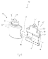
- Fig. 1 shows a perspective side view of a first reservoir 10 and a second reservoir 11 for a container according to the invention 12.
- the first reservoir 10 and the second reservoir 11 are formed as separate elements or separate sub-containers, which are spatially separated from each other as shown here.
- the first reservoir 10 and the second reservoir 11 are formed identically.
- the second reservoir 11 is rotated by 180 ° about its vertical axis to the first reservoir 10.
- the first reservoir 10 and the second reservoir 11 are arranged offset to one another according to this exemplary illustration.
- a first plug-in means 14 as a dovetail groove 14 and a second plug-in means 15 as a dovetail socket 15 is formed.
- the first plug-in means 14 and the second plug-in means 15 are formed with respect to size and shape corresponding to each other.
- the two reservoirs 10, 11 are each assigned a first plug-in means 14 and a second plug-in means 15.
- the two plug-in means 14, 15 are transverse, here at right angles, to the vertical axis of the reservoir 10 and 11 arranged side by side.
- the two plug-in means 14, 15 are arranged such that a virtual plug-in axis 16 at right angles to the vertical axis of Reservoirs 10, 11 yields.
- the reservoirs 10, 11 each have a bottle neck-like outlet 18, which extends from an upper side 19 of the reservoir 10, 11 in the longitudinal direction of the vertical axis of the reservoir 10, 11.
- the outlet 18 has a locking collar 20 and an opening 21.
- FIG. 3 shows a further perspective side view of a container 12 according to the invention. This representation largely corresponds to that according to FIG Fig. 2 , here however, the lid 23 is in its open position. The sealing member 25 is released from the lid 23 and the lid 23 is pivoted about 180 ° about the bearing 24 of the sealing member 25 away.
- the cap 22 has a first dropper 27 and a second dropper 28.
- the first dropper 27 is operatively connected to the outlet 18 of the first reservoir 10 and the second dropper 28 is operatively connected to the outlet 18 of the second reservoir 11.
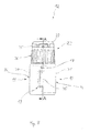
- Fig. 5 shows a sectional side view of the container 12 according to the invention according to the section line BB Fig. 4 ,
- the cap 22 surrounds the outlets 18 of the two reservoirs 10, 11.
- the locking collar 20 of the two reservoirs 10 and 11 in a arranged on an inner side of the cap 22 recess 39 a.
- the cap 22 can be positively locked with the two reservoirs 10, 11, wherein an undesired release of the cap 22 of the two Reserovirs 10, 11 is sufficiently prevented due to the latching connection.
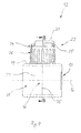
- Fig. 7 shows a further side view of the container 12 according to the invention.
- the sides 37 with the pressing surfaces 36 of the two reservoirs 10, 11 extend substantially parallel to the connecting sides 17 of the two reservoirs 10, 11.
- the sides 37 form the outer periphery of the container 12.
- the dovetail base 15 and the dovetail groove 14 have, in the direction of the plug-in axis 16, a width which corresponds to half the width of the reservoir 10 or 11 along the plug-in axis 16.
- the plug-in device 13 is completely made when the dovetail socket 15 of the two reservoirs 10, 11 strike each other.
- the two reservoirs 10, 11 form a container 12, which has an ellipsoidal outer circumference or cross-section below the outlets 18.
- the two fluids can be collected and mixed in a mixing container, not shown here.
- the two fluids can be simultaneously in two separate collecting areas and / or shells are delivered.
- a mixture or lamination of the two fluids takes place only at the place of use, for example in the context of a dental application directly to a patient.
- the discharge quantity of the drippers 27, 28 is determined by means of the selected diameter, the length and / or the shape of the channel of the dripper 27, 28.
Landscapes
- Engineering & Computer Science (AREA)
- Mechanical Engineering (AREA)
- Package Specialized In Special Use (AREA)
- Containers And Packaging Bodies Having A Special Means To Remove Contents (AREA)
Abstract
Die Erfindung betrifft ein Behältnis (12) zum dosierbaren Abgeben eines Fluids mit einem ersten verschließbaren Reservoir (10) für ein erstes Fluid, wobei das erste Reservoir (10) mittels einer Verbindungseinrichtung (13) mit einem separaten zweiten verschließbaren Reservoir (11) zum Herstellen eines Verbunds verbindbar ist, und die Verbindungseinrichtung (13) des ersten Reservoirs (10) und des zweiten Reservoirs (11) jeweils einen Stecksockel (15) und eine Stecknut (14) aufweist, wobei der Stecksockel (15) des ersten Reservoirs (10) in die Stecknut (14) des zweiten Reservoirs (11) und der Stecksockel (15) des zweiten Reservoirs (11) in die Stecknut (14) des ersten Reservoirs (10) einführbar ist. Zum Vereinfachen des dosierbaren Abgeben zweier Fluide ist das Behältnis (12) dadurch gekennzeichnet, dass das der Stecksockel (15) des ersten Reservoirs (10) als ein Anschlag für den Stecksockel (15) des zweiten Reservoirs (11) und der Stecksockel (15) des zweiten Reservoirs (11) als ein Anschlag für den Stecksockel (15) des ersten Reservoirs (10) dient.The invention relates to a container (12) for dosing a fluid with a first closable reservoir (10) for a first fluid, wherein the first reservoir (10) by means of a connecting device (13) with a separate second sealable reservoir (11) for manufacturing a compound is connectable, and the connecting means (13) of the first reservoir (10) and the second reservoir (11) each have a plug socket (15) and a plug-in groove (14), wherein the plug socket (15) of the first reservoir (10) into the insertion groove (14) of the second reservoir (11) and the plug socket (15) of the second reservoir (11) into the insertion groove (14) of the first reservoir (10) can be inserted. To simplify the dispensable dispensing of two fluids, the container (12) is characterized in that the plug socket (15) of the first reservoir (10) acts as a stop for the plug socket (15) of the second reservoir (11) and the plug socket (15). of the second reservoir (11) serves as a stop for the plug-in base (15) of the first reservoir (10).
Description
Die Erfindung betrifft ein Behältnis zum dosierbaren Abgeben eines Fluids mit einem ersten verschließbaren Reservoir für ein erstes Fluid, wobei das erste Reservoir mittels einer Verbindungseinrichtung mit einem separaten zweiten verschließbaren Reservoir zum Herstellen eines Verbunds verbindbar ist, und die Verbindungseinrichtung des ersten Reservoirs und des zweiten Reservoirs jeweils einen Stecksockel und eine Stecknut aufweist, wobei der Stecksockel des ersten Reservoirs in die Stecknut des zweiten Reservoirs und der Stecksockel des zweiten Reservoirs in die Stecknut des ersten Reservoirs einführbar ist.The invention relates to a container for the metered dispensing of a fluid with a first closable reservoir for a first fluid, wherein the first reservoir is connectable by means of a connecting device with a separate second sealable reservoir for establishing a composite, and the connecting means of the first reservoir and the second reservoir each having a plug-in base and a plug-in groove, wherein the plug-in base of the first reservoir into the plug-in groove of the second reservoir and the plug-in base of the second reservoir can be inserted into the plug-in groove of the first reservoir.
Aus der
Nachteilig ist, dass zum Mischen zweier Komponenten eines 2-Komponenten-Materials zwei separate und völlig eigenständige Behältnisse eingesetzt werden müssen, die jeweils eine der beiden fluiden Komponenten enthalten. Das Abgeben der Fluide aus den Behältnissen muss nacheinander oder bei gleichzeitiger Abgabe aus beiden Behältnissen zweihändig erfolgen. Hierbei besteht die Gefahr, dass die beiden Fluide in einem ungünstigen und nicht optimalen Mischungsverhältnis zum Realisieren des 2-Komponenten-Materials abgeben werden. Zudem ist die Herstellung der erforderlichen Mischung umständlich.The disadvantage is that for mixing two components of a 2-component material two separate and completely separate containers must be used, each containing one of the two fluid components. The discharge of the fluids from the containers must be done in succession or with simultaneous delivery from two containers with two hands. There is a risk here that the two fluids will give off in an unfavorable and non-optimal mixing ratio for realizing the 2-component material. In addition, the preparation of the required mixture is cumbersome.
Es ist daher das der Erfindung zugrunde liegende Problem, ein Behältnis der eingangs genannten Art anzugeben, wobei ein dosierbares Abgeben zweier Fluide und/oder eine Bedienung des Behältnisses vereinfacht ist.It is therefore the problem underlying the invention to provide a container of the type mentioned, wherein a metered dispensing two fluids and / or an operation of the container is simplified.
Das der Erfindung zugrunde liegende Problem wird durch ein Behältnis der eingangs genannten Art gelöst, bei dem der Stecksockel des ersten Reservoirs als ein Anschlag für den Stecksockel des zweiten Reservoirs und der Stecksockel des zweiten Reservoirs als ein Anschlag für den Stecksockel des ersten Reservoirs dient.The problem underlying the invention is solved by a container of the type mentioned, in which the socket of the first reservoir serves as a stop for the socket of the second reservoir and the socket of the second reservoir as a stop for the socket of the first reservoir.
Hierbei ist von Vorteil, dass aufgrund der Verbindungseinrichtung das erste Reservoir und das zweite Reservoir ein gemeinsames Behältnis bilden. Hierbei kann das Behältnis das erste Reservoir und das zweite Reservoir aufweisen. Hierdurch ist die, insbesondere gleichzeitige, dosierbare Abgabe zweier Fluide erheblich vereinfacht. Insbesondere ermöglicht das Behältnis ein gemeinsames und/oder gleichzeitiges Abgeben des dem ersten Reservoir und dem zweiten Reservoir zugeordneten Fluids. Vorzugsweise ist das zweite Reservoir für ein von dem ersten Fluid verschiedenes zweites Fluid vorgesehen. Insbesondere ist mit dem erfindungsgemäßen Behältnis ein vorgegebenes Verhältnis und/oder Mischungsverhältnis der beiden Fluide einfacher realisierbar. Vorzugsweise ist die Verbindungseinrichtung unmittelbar dem ersten Reservoir und/oder dem zweiten Reservoir zugeordnet. Hierdurch ist ein separates Teil zum Verbinden der beiden Reservoirs verzichtbar. Insbesondere ist die Verbindungseinrichtung einstückig mit dem ersten Reservoir und/oder dem zweiten Reservoir ausgebildet.It is advantageous that form the first reservoir and the second reservoir a common container due to the connection means. In this case, the container may have the first reservoir and the second reservoir. As a result, the, in particular simultaneous, metered delivery of two fluids is considerably simplified. In particular, the container allows a common and / or simultaneous dispensing of the first reservoir and the second reservoir associated fluid. Preferably, the second reservoir is provided for a second fluid other than the first fluid. In particular, a predetermined ratio and / or mixing ratio of the two fluids can be realized more easily with the container according to the invention. Preferably, the connection device is assigned directly to the first reservoir and / or the second reservoir. As a result, a separate part for connecting the two reservoirs is dispensed with. In particular, the connecting device is formed integrally with the first reservoir and / or the second reservoir.
Insbesondere ist das Behältnis selbst zum dosierbaren Abgeben eines Fluids aus dem ersten Reservoir und/oder dem zweiten Reservoir ausgebildet. Das Behältnis kann per Hand, insbesondere einhändig, zum dosierbaren Abgeben des Fluids oder der Fluide eingesetzt werden. Vorzugsweise ist das dosierbare Abgeben ohne, insbesondere zusätzliche, Hilfsmittel und/oder Vorrichtungen realisierbar. Das Behältnis kann zum werkzeuglosen Betätigen und/oder Verwenden ausgelegt sein. Vorzugsweise ist dies durch geeignete Tropfer und/oder eine mindestens teilweise elastisch ausgebildete Wandung zum Eindrücken des Behältnisses realisiert. Hierdurch ist die Bedienbarkeit vereinfacht.In particular, the container itself is designed for metered dispensing of a fluid from the first reservoir and / or the second reservoir. The container can be used by hand, especially one-handed, for metered dispensing of the fluid or fluids. Preferably, the dispensable dispensing without, in particular additional, aids and / or devices can be realized. The container can be designed for tool-free operation and / or use. This is preferably realized by suitable drippers and / or an at least partially elastically formed wall for pressing in the container. As a result, the operability is simplified.
Vorzugsweise dient das Behältnis zum Aufbewahren und/oder Abgeben eines medizinischen und/oder zahnmedizinischen Materials, insbesondere eines Dentalmaterials. Insbesondere ist das Fluid, vorzugsweise das erste Fluid des ersten Reservoirs und das zweite Fluid des zweiten Reservoirs, als ein fließfähiges Dentalmaterial ausgebildet. Insbesondere ist das Dentalmaterial eines der folgenden Materialien: ein Komposit, ein Haftvermittler, ein Bonding, ein Zement-Liquid, ein Pharmaka, eine endodontische Spülflüssigkeit, eine Färbelösung, eine Harz-Emulsion (insbesondere mit einer Mischkugel), ein Keramikliquid, ein Bleaching-Mittel und/oder ein Ätzmittel.The container is preferably used for storing and / or dispensing a medical and / or dental material, in particular a dental material. In particular, the fluid, preferably the first fluid of the first reservoir and the second fluid of the second reservoir, is formed as a flowable dental material. In particular, the dental material is one of the following materials: a composite, a primer, a bonding, a cement liquid, a pharmaceutical, an endodontic irrigation fluid, a staining solution, a resin emulsion (especially with a mixing ball), a ceramic fluid, a bleaching Agent and / or an etchant.
Das Dentalmaterial kann als ein 2-Komponeten-Material ausgebildet sein. Eine erste Komponente des 2-Komponenten-Materials kann das erste Fluid des ersten Reservoirs und eine zweite Komponente des 2-Komponenten-Materials das zweite Fluid des zweiten Reservoirs sein. Insbesondere weist das Fluid ein oder mehrere der folgenden Inhaltsstoffe auf:
- Aceton, Ethanol, Wasser, Methylmethacrylat (insbesondere Bisphionol-A-(di)-methacrylat, Decamethylen-di-methacrylat, Urethan-di-methacrylat und/oder Triethylenglycol-di-methacrylat), Methylethylketon, Phosphorsäure, Maleinsäure, Kampferchinon, Benzoinmethylester, Acylphospinoxid, Glutaraldehyd, Natriumfluorid, Polyalkenoat (methacryliert), Acrylamidosulfonsäure, funktionalisiertes amorphes Siliciumdioxid, PENTA (Dipentataerytritolpenacrylat-Phosphorsäure-Monomer), Cetylaminhydrofluorid, hochdisperses Siliciumdioxid, Säureacrylat, HEMA 2-hydroxethyl methacrylate, BHT Butylated Hydroxy Toluene, Pyro-EMA (Phosphoric acid modified methacrylate), Ethyl-4-dimethylaminobenzoate.
- Acetone, ethanol, water, methyl methacrylate (especially bisphionol A (di) methacrylate, decamethylene di-methacrylate, urethane di-methacrylate and / or triethylene glycol di-methacrylate), methyl ethyl ketone, phosphoric acid, maleic acid, camphorquinone, benzoin methyl ester, Acylphospine oxide, glutaraldehyde, sodium fluoride, polyalkenoate (methacrylated), acrylamidosulfonic acid, functionalized amorphous silica, PENTA (dipentaerytropitol-acrylate-phosphoric acid monomer), cetylamine hydrofluoride, fumed silica, acid acrylate, HEMA 2-hydroxethyl methacrylate, BHT butylated hydroxy toluene, pyro-EMA (Phosphoric acid modified methacrylates), ethyl 4-dimethylaminobenzoates.
Vorzugsweise hat das Behältnis, das erste Reservoir und/oder das zweite Reservoir ein Füllvolumen bis maximal 10 ml, insbesondere bis maximal 5 ml. Insbesondere liegt das Füllvolumen im Bereich von 2 ml bis 10 ml. Besonders bevorzugt ist das Füllvolumen 2,5 ml, 3 ml, 5 ml, 8 ml oder 10 ml. Insbesondere bezieht sich das Füllvolumen auf eine eingefüllte Menge an Fluid. Vorzugsweise ist ein Leervolumen des Behältnisses, des ersten Reservoirs und/oder des zweiten Reservoirs größer als das zugehörige Füllvolumen. Hierdurch kann das abgefüllte Fluid, sofern gewünscht oder notwendig, vor dem Abgeben bzw. der Verwendung aufgeschüttelt werden. Insbesondere ist das Leervolumen um 2 ml bis 3 ml größer als das Füllvolumen. Besonders bevorzugt liegt das Leervolumen im Bereich von 6 ml bis 7 ml. Das Leervolumen des Behältnisses, des ersten Reservoirs und/oder des zweiten Reservoirs kann sich aus dem Leervolumen des Reservoirs inklusive des Leervolumens eines, insbesondere flachenhalsartigen, Auslasses ergeben.Preferably, the container, the first reservoir and / or the second reservoir has a filling volume of at most 10 ml, in particular up to a maximum of 5 ml. In particular, the filling volume is in the range from 2 ml to 10 ml. Particularly preferably, the filling volume is 2.5 ml, 3 ml, 5 ml, 8 ml or 10 ml. In particular, the filling volume refers to a filled amount of fluid. Preferably, a void volume of the container, the first reservoir and / or the second reservoir is greater than the associated filling volume. This allows the bottled fluid, if desired or necessary, to be shaken before dispensing or use. In particular, the void volume is larger by 2 ml to 3 ml than the filling volume. More preferably, the void volume is in the range of 6 ml to 7 ml. The void volume of the container, the first reservoir and / or the second reservoir may result from the void volume of the reservoir including the void volume of a, in particular flat neck-like, outlet.
Gemäß einer weiteren Ausführungsform ist die Verbindungseinrichtung als eine Steckeinrichtung zum Herstellen einer kraftschlüssigen und/oder formschlüssigen Steckverbindung ausgebildet. Insbesondere ist die Steckeinrichtung als eine Schwalbenschwanzeinrichtung ausgebildet. Eine Steckeinrichtung und/oder Schwalbenschwanzverbindung ermöglicht eine einfach herzustellende und zugleich ausreichend zuverlässige Verbindung zwischen zwei Teilbehältnissen, wie beispielsweise hier dem ersten Reservoir und dem zweiten Reservoir. Insbesondere ist das erste Reservoir ein erstes Teilbehältnis und das zweite Reservoir ein zweites Teilbehältnis. Vorzugsweise weist das erste Reservoir und das zweite Reservoir jeweils identisch ausgebildete Steckmittel, insbesondere Schwalbenschwanzmittel, auf. Somit ist das erste Reservoir bzw. das erste Teilbehältnis und das zweite Reservoir bzw. das zweite Teilbehältnis mindestens in Bezug auf die Verbindungseinrichtung identisch ausbildbar, wodurch die Herstellung vereinfacht und/oder vergünstigt ist.According to a further embodiment, the connecting device is designed as a plug-in device for producing a non-positive and / or positive plug-in connection. In particular, the plug-in device is designed as a dovetail device. A plug-in device and / or dovetail connection allows an easy to manufacture and at the same time sufficiently reliable connection between two partial containers, such as, for example, the first reservoir and the second reservoir. In particular, the first reservoir is a first sub-container and the second reservoir is a second sub-container. Preferably, the first reservoir and the second reservoir each have identically formed insertion means, in particular dovetail means. Thus, the first reservoir or the first sub-container and the second reservoir or the second sub-container can be formed identically at least with respect to the connecting device, whereby the production is simplified and / or discounted.
Nach einer Weiterbildung hat das erste Reservoir und/oder das zweite Reservoir einen halbkreisartigen oder halbellipsoiden Querschnitt. Insbesondere ergibt sich ein halbkreisartiger oder halbellipsoider Querschnitt und/oder Außenumfang bei einer Draufsicht auf das Reservoir bzw. Teilbehältnis. Insbesondere hat das erste Reservoir und/oder das zweite Reservoir eine im Wesentlichen ebene Verbindungsseite. Vorzugsweise ist an der Verbindungsseite ein Steckmittel angeordnet. Das Steckmittel und/oder eine Steckachse kann sich zum Herstellen der Steckverbindung parallel zu einer Hauptachse des halbellipsoiden Querschnitts erstrecken. Zum Herstellen der Verbindung der beiden Reservoirs bzw. Teilbehältnissen miteinander zum Bilden des Behältnisses sind die Verbindungsseiten und/oder die Steckmittel des ersten und zweiten Reservoirs aneinander zugewandt. Die beiden miteinander verbundenen Reservoirs können einen kreisartigen oder ellipsoiden Umfang für das Behältnis bilden.According to a development, the first reservoir and / or the second reservoir has a semicircular or semi-ellipsoidal cross section. In particular, a semicircular or semi-ellipsoidal cross section and / or outer circumference results in a plan view of the reservoir or partial container. In particular, the first reservoir and / or the second reservoir has a substantially flat connection side. Preferably, a plug-in means is arranged on the connection side. The plug-in means and / or a plug-in axis may extend parallel to a main axis of the semi-ellipsoidal cross section for producing the plug connection. To connect the two reservoirs or partial containers with one another to form the container, the connection sides and / or the insertion means of the first and second reservoirs face one another. The two interconnected reservoirs may form a circular or ellipsoidal perimeter for the container.
Vorzugsweise weist das erste Reservoir und/oder das zweite Reservoir jeweils an einer von der Verbindungsseite abgewandten, insbesondere äußeren, Seite jeweils eine Pressfläche auf. Im Bereich der Pressflächen ist das Wandmaterial der ersten und zweiten Reservoirs nach innen elastisch eindrückbar. Hierdurch ist das Abgeben eines Tropfens erleichtert. Vorzugsweise erstreckt sich die Pressfläche mindestens im Wesentlichen in Längsrichtung und/oder parallel zu einer Steckachse zum Herstellen der Steckverbindung. Insbesondere erstreckt sich die Pressfläche mindestens im Wesentlichen parallel zu einer Hauptachse eines halbellipsoiden Querschnitts des ersten Reservoirs oder des zweiten Reservoirs. Bei miteinander verbundenen Reservoirs können sich die Pressflächen der beiden Reservoirs mindestens im Wesentlichen parallel zu einer Hauptachse eines ellipsoiden Querschnitts des Behältnisses erstrecken. Hierdurch wird ein intuitives Greifen des Behältnisses begünstigt, bei dem eine Person den Daumen an eine Pressfläche eines der beiden Reservoirs und mindestens einen Finger an eine Pressfläche des jeweils anderen Reservoirs anlegt. Der Versuch eines Zusammendrückens des Behältnisses in Richtung der, insbesondere aufgrund der Steckmittel versteiften, Steckachse ist hierdurch vermeidbar.Preferably, the first reservoir and / or the second reservoir in each case on a side facing away from the connection side, in particular outer side each have a pressing surface. In the area of the pressing surfaces, the wall material of the first and second reservoirs can be elastically pressed inwards. This makes dispensing a drop easier. Preferably, the pressing surface extends at least substantially in the longitudinal direction and / or parallel to a plug-in axis for producing the plug connection. In particular, the pressing surface extends at least substantially parallel to a main axis of a semi-ellipsoidal cross-section of the first reservoir or of the second reservoir. In interconnected reservoirs, the pressing surfaces of the two reservoirs may extend at least substantially parallel to a major axis of an ellipsoidal cross section of the container. In this way, an intuitive gripping of the container is favored, in which a person applies the thumb to a pressing surface of one of the two reservoirs and at least one finger to a pressing surface of the respective other reservoir. The attempt of squeezing the container in Direction of, in particular stiffened due to the plug-in means, plug-in axis is thereby avoided.
Die Verbindungseinrichtung des ersten Reservoirs und des zweiten Reservoirs, insbesondere das Steckmittel, können jeweils einen Stecksockel und eine Stecknut aufweisen. Vorzugsweise ist der Stecksockel des ersten Reservoirs in die Stecknut des zweiten Reservoirs und der Stecksockel des zweiten Reservoirs in die Stecknut des ersten Reservoirs einführbar. Hierdurch ist mittels für das erste Reservoir und das zweite Reservoir identisch ausgebildeten Verbindungseinrichtungen und/oder Steckmitteln die Steckverbindung auf einfache und effektive Weise herstellbar. Insbesondere ist der Stecksockel als ein Schwalbenschwanzsockel und die Stecknut als eine Schwalbenschwanznut ausgebildet.The connecting device of the first reservoir and the second reservoir, in particular the plug-in means, may each have a plug-in base and a plug-in groove. Preferably, the plug-in base of the first reservoir can be inserted into the plug-in groove of the second reservoir and the plug-in socket of the second reservoir into the plug-in groove of the first reservoir. As a result, the connector can be produced in a simple and effective manner by means of connecting means and / or plug-in means of identical construction for the first reservoir and the second reservoir. In particular, the plug-in base is designed as a dovetail socket and the plug-in groove as a dovetail groove.
Vorzugsweise dient der Stecksockel des ersten Reservoirs als ein Anschlag für den Stecksockel des zweiten Reservoirs. Hierdurch kann der Verschiebeweg der beiden Reservoirs zueinander begrenzt sein, wobei dem Anwender bei der Herstellung der Verbindung der beiden Reservoirs mittels des Anschlags eine fühlbare Rückkopplung für eine erfolgreiche Verbindungsherstellung vermittelbar ist. Insbesondere dient der Stecksockel des zweiten Reservoirs als ein Anschlag für den Stecksockel des ersten Reservoirs. Vorzugsweise sind das erste Reservoir und das zweite Reservoir zum Herstellen der Verbindung mittels der Verbindungseinrichtung um 180° um die Hochachse des ersten und/oder zweiten Reservoirs verdreht zueinander angeordnet sind. Insbesondere erflogt zum Herstellen einer Verbindung der beiden Reservoirs miteinander aufgrund einer Bewegung der beiden Reservoirs quer, insbesondere rechtwinklig, zur Hochachse der Reservoirs.Preferably, the socket of the first reservoir serves as a stop for the socket of the second reservoir. In this way, the displacement of the two reservoirs can be limited to each other, wherein the user in the preparation of the connection of the two reservoirs by means of the stop a tactile feedback for a successful connection can be mediated. In particular, the socket of the second reservoir serves as a stop for the socket of the first reservoir. Preferably, the first reservoir and the second reservoir for establishing the connection by means of the connecting means are arranged rotated by 180 ° about the vertical axis of the first and / or second reservoir to each other. In particular, in order to establish a connection of the two reservoirs with each other due to a movement of the two reservoirs transversely, in particular at right angles, flows to the vertical axis of the reservoirs.
Gemäß einer weiteren Ausführungsform hat das erste Reservoir und/oder das zweite Reservoir einen, insbesondere auf einer Oberseite angeordneten und/oder flaschenhalsartigen, Auslass. Mittels des Auslasses kann das Fluid des ersten Reservoirs bzw. des zweiten Reservoirs abgegeben werden. Vorzugsweise ist das erste Reservoir und/oder das zweite Reservoir aus einem elastisch verformbaren Material. Hierdurch wird eine dosierbare Abgabe des Fluids aus dem Auslass, insbesondere aus einem mit dem Auslass verbundenen Tropfer, vereinfacht. Insbesondere ist die Abgabemenge durch die Stärke des Eindrückens und/oder Quetschens des elastisch verformbaren Materials steuerbar. Besonders bevorzugt weist das Material des ersten Reservoirs und/oder des zweiten Reservoirs Barriereeigenschaften in Bezug auf das erste Fluid und/oder das zweite Fluid, vorzugsweise gegen eine Permeation von Wasserdampf, Methylacrylatharze, Ethanol und/oder Lösungsmittel, insbesondere Aceton, auf. Insbesondere ist aufgrund der Barriereeigenschaften eine Permeation bzw. Durchdringung des Reservoirs verhindert. Vorzugsweise verhindern die Barriereeigenschaften des ersten Reservoirs und/oder zweiten Reservoirs eine Permeation der Inhaltsstoffe des Fluids und/oder des Fluids selbst. Hierdurch ist beispielsweise bei der Lagerung von zwei Komponenten eines 2-Komponenten-Materials eine ungewünschte Reaktion der beiden Komponenten bei der Lagerung und/oder dem Transport der miteinander verbundenen Reservoirs vermeidbar. Insbesondere sind die Barriereeigenschaften des Materials derart, dass eine Permeation für Sauerstoff, insbesondere für eine verbesserte Lagerstabilität des Fluids in dem ersten und/oder zweiten Reservoir, ermöglicht ist.According to a further embodiment, the first reservoir and / or the second reservoir has an outlet, in particular arranged on an upper side and / or bottle-neck-like. By means of the outlet, the fluid of the first reservoir or of the second reservoir can be dispensed. Preferably, the first reservoir and / or the second reservoir is made of an elastically deformable material. In this way, a metered dispensing of the fluid from the outlet, in particular from a dropper connected to the outlet, is simplified. In particular, the discharge amount is controllable by the strength of the indentation and / or squeezing of the elastically deformable material. Particularly preferably, the material of the first reservoir and / or the second reservoir has barrier properties with respect to the first fluid and / or the second fluid, preferably against permeation of water vapor, methyl acrylate resins, ethanol and / or solvents, in particular acetone. In particular, due to the barrier properties, permeation or penetration of the reservoir is prevented. Preferably, the barrier properties of the first reservoir and / or second reservoir prevent permeation of the ingredients of the fluid and / or fluid As a result, for example, during the storage of two components of a 2-component material, an undesired reaction of the two components during the storage and / or transport of the interconnected reservoirs can be avoided. In particular, the barrier properties of the material are such as to permit permeation of oxygen, in particular for improved storage stability of the fluid in the first and / or second reservoir.
Die Barriereeigenschaften können dadurch erhöht sein, dass das erste Reservoir und das zweite Reservoir abgesehen von der Verbindungseinrichtung räumlich, insbesondere mittels eines Luftspaltes, voneinander getrennt sind. Insbesondere kann die Materialschicht und/oder Wanddicke des ersten Reservoirs und/oder zweiten Reservoirs im Bereich der einander zugewandten Verbindungsseite und/oder der Verbindungseinrichtung dicker ausgebildet sein als im einem nicht unmittelbar einander zugewandten Bereich der beiden Reservoire.The barrier properties can be increased by the fact that the first reservoir and the second reservoir apart from the connecting device are spatially separated, in particular by means of an air gap. In particular, the material layer and / or wall thickness of the first reservoir and / or second reservoir in the region of the mutually facing connection side and / or the connecting device may be formed thicker than in a not directly facing each other region of the two reservoirs.
Das erste Reservoir und/oder das zweite Reservoir kann zum Bereitstellen der Barriereeigenschaften aus einem einlagigen oder mehrlagigen, insbesondere dreilagigen, Material gebildet sein. Bei einem dreilagigen Aufbau kann eine Außenschicht und/oder eine Innenschicht aus einem Polyolefin, insbesondere inklusive einem Haftvermittler, ausgebildet sein. Als Polyolefin kann Polypropylen oder Polyethylen verwendet werden. Eine zwischen der Außenschicht und der Innenschicht angeordnete Zwischenschicht kann aus einem Ethylen-Vinylalkohol-Copolymer (EVOH) bestehen.The first reservoir and / or the second reservoir can be formed to provide the barrier properties of a single-layer or multi-layer, in particular three-ply, material. In the case of a three-layer structure, an outer layer and / or an inner layer may be formed from a polyolefin, in particular including an adhesion promoter. As the polyolefin, polypropylene or polyethylene can be used. An intermediate layer disposed between the outer layer and the inner layer may be made of an ethylene-vinyl alcohol copolymer (EVOH).
Das erste Reservoir und/oder das zweite Reservoir kann einen einlagigen Aufbau aus einem einzigen Material und/oder einer einzigen Materialmischung aufweisen. Hierdurch ist ein mehrschichtiger Laminataufbau vermeidbar. Vorzugsweise ist das Material für den einlagigen Aufbau eine Mischung aus einem Polyolefin, insbesondere einem Polypropylen oder einem Polyethylen, mit einem Zusatzstoff zum Verstärken und/oder Erzeugen der Barriereeigenschaften. Der Zusatzstoff kann Nylon, Polyamid und/oder EVOH aufweisen. Insbesondere weist der Zusatzstoff Plättchen aus Nylon, Polyamid und/oder EVOH auf. Diese Plättchen können sich innerhalb des Schicht aus dem Material für den einlagigen Aufbau mindestens teilweise einander überlagern. Hierdurch sind die Barriereeigenschaften deutlich verbessert. Auf einen zusätzlichen Haftvermittler kann verzichtet werden. Insbesondere sind das erste Reservoir und/oder das zweite Reservoir jeweils in einem einzigen Herstellungsschritt mittels des Materials für den einlagigen Aufbau herstellbar. Vorzugsweise wird für die Herstellung des ersten Reservoirs und/oder des zweiten Reservoirs lediglich ein einziger Extruder benötigt.The first reservoir and / or the second reservoir may have a single-layered construction of a single material and / or a single material mixture. As a result, a multilayer laminate structure is avoidable. Preferably, the material for the single-layer construction is a mixture of a polyolefin, in particular a polypropylene or a polyethylene, with an additive for reinforcing and / or generating the barrier properties. The additive may include nylon, polyamide and / or EVOH. In particular, the additive has platelets of nylon, polyamide and / or EVOH. These platelets may at least partially overlap one another within the layer of material for the single-layer construction. As a result, the barrier properties are significantly improved. On an additional primer can be dispensed with. In particular, the first reservoir and / or the second reservoir can each be produced in a single production step by means of the material for the single-layer structure. Preferably, only a single extruder is needed for the production of the first reservoir and / or the second reservoir.
Nach einer Weiterbildung ist eine Sicherungseinrichtung zum zusätzlichen Sichern der miteinander verbundenen Reservoirs und/oder der Verbindungseinrichtung gegen ein unbeabsichtigtes Lösen vorgesehen. Insbesondere ist mittels der Sicherungseinrichtung eine Relativbewegung des ersten Reservoirs in Bezug zum zweiten Reservoir verhindert. Vorzugsweise ist die Sicherungseinrichtung als eine Kappe ausgebildet. Mit der Kappe kann ein Auslass des ersten Reservoirs gemeinsam mit einem Auslass des zweiten Reservoirs umschlossen, abgedeckt und/oder verschlossen sein. Somit kann die Sicherungseinrichtung mindestens eine Doppelfunktion haben, nämlich neben dem Sichern der Verbindung der beiden Reservoirs miteinander zusätzlich eine, insbesondere öffenbare, Verschließung der Auslässe der beiden Reservoirs bereit zu stellen. Insbesondere ist die Kappe quer, vorzugsweise rechtwinklig, zu einer Steckachse, in deren Längsrichtung das erste Reservoir und/oder das zweite Reservoir zum Herstellen einer Steckverbindung bewegbar sind, zum Blockieren einer Verschiebung der beiden Reservoirs gegeneinander, insbesondere entlang der Steckachse, auf die Auslässe aufsetzbar. Insbesondere greift die Kappe mindestens teilweise in die Auslässe ein. Die Kappe kann in einem 2-Komponenten-Spritzgussverfahren hergestellt werden. Das erste Reservoir und/oder das zweite Reservoir kann mittels Extrusionsblasformen, Spritzblasen und/oder Spritzgießen hergestellt werden.According to a development, a securing device for additionally securing the interconnected reservoirs and / or the connecting device against unintentional release is provided. In particular, by means of Securing device prevents a relative movement of the first reservoir with respect to the second reservoir. Preferably, the securing device is designed as a cap. With the cap, an outlet of the first reservoir can be enclosed, covered and / or closed together with an outlet of the second reservoir. Thus, the securing device can have at least one double function, namely, in addition to securing the connection of the two reservoirs with each other, in addition to provide a, in particular openable, closure of the outlets of the two reservoirs. In particular, the cap is transversely, preferably at right angles, to a plug-in axis, in the longitudinal direction of the first reservoir and / or the second reservoir for producing a connector are movable, for blocking a displacement of the two reservoirs against each other, in particular along the thru axle, placed on the outlets , In particular, the cap engages at least partially in the outlets. The cap can be made in a 2-component injection molding process. The first reservoir and / or the second reservoir can be produced by means of extrusion blow molding, injection blow molding and / or injection molding.
Vorzugsweise hat die Kappe einen ersten Tropfer, der mit dem Auslass des ersten Reservoirs zusammenwirkt. Insbesondere hat die Kappe einen zweiten Tropfer, der mit dem Auslass des zweiten Reservoirs zusammenwirkt. Mittels der Tropfer ist eine dosierbare Abgabe der Fluide erleichtert. Die Tropfer können derart ausgelegt sein, dass das Tropfengewicht im Bereich von 1 mg bis 2 mg, insbesondere um etwa 1,5 mg, liegt. Bei einer Dosierung von 5 Tropfen kann die Abweichung im Bereich von ±0,5 mg bis etwa ±2 mg, insbesondere um etwa ±1,5 mg, liegen.Preferably, the cap has a first dropper which cooperates with the outlet of the first reservoir. In particular, the cap has a second dropper which cooperates with the outlet of the second reservoir. By means of the dropper a metered delivery of the fluids is facilitated. The drippers may be designed such that the drop weight is in the range of 1 mg to 2 mg, in particular about 1.5 mg. At a dosage of 5 drops, the deviation may range from ± 0.5 mg to about ± 2 mg, especially about ± 1.5 mg.
Vorzugsweise sind der erste Tropfer und der zweite Tropfer für eine vorgegebene Abgabemenge und/oder für ein vorgegebenes Mischungsverhältnis der Fluide aus dem ersten Reservoir und dem zweiten Reservoir aufeinander abgestimmt. Somit sind die beiden Fluide aus den beiden Reservoirs auf einfache Weise und in einem gewünschten Mischungsverhältnis abgebbar. Vorzugsweise sind die Durchmesser des ersten Tropfers und des zweiten Tropfers voneinander abweichend und in Abhängigkeit von der Viskosität, den rheologischen und/oder den physikalischen Eigenschaften der dem ersten Tropfer bzw. des zweiten Tropfers zugeordneten Fluide ausgebildet. Insbesondere ist die Gestaltung des ersten Tropfers und des zweiten Tropfers in Abhängigkeit von den Materialeigenschaften der jeweils zugeordneten Fluide zum Aufnehmen in dem ersten Reservoir und dem zweiten Reservoir sowie des vorgegebenen Mischungsverhältnisses der beiden Fluide bzw. Komponenten angepasst. Die beiden Tropfer können jeweils einen, insbesondere dem Reservoir zugewandten, zylindrischen Bereich und einen sich ausgehend von dem zylindrischen Bereich von dem Reservoir weg erweiternden konischen Bereich aufweisen. Hierbei kann der Innendurchmesser am Eingang und/oder am Ausgang des Tropfers, die Länge des gesamten Tropferkanals und/oder des zylindrischen Bereichs, und/oder die Gestaltung des konischen Bereichs zum Erreichen des vorgegebenen Mischungsverhältnisses angepasst sein.Preferably, the first dropper and the second dropper for a predetermined discharge amount and / or for a predetermined mixing ratio of the fluids from the first reservoir and the second reservoir are coordinated. Thus, the two fluids from the two reservoirs can be delivered in a simple manner and in a desired mixing ratio. The diameters of the first dropper and the second dropper are preferably deviating from one another and are formed as a function of the viscosity, the rheological and / or the physical properties of the fluids assigned to the first dropper or of the second dropper. In particular, the design of the first dropper and the second dropper is adapted depending on the material properties of the respectively associated fluids for taking up in the first reservoir and the second reservoir and the predetermined mixing ratio of the two fluids or components. The two drippers may each have a cylindrical region, in particular facing the reservoir, and a conical region which widens away from the reservoir starting from the cylindrical region. Here, the inner diameter at the inlet and / or at the exit of the dropper, the length of the entire dropper channel and / or the cylindrical portion, and / or the Be adapted design of the conical region to achieve the predetermined mixing ratio.
Insbesondere hat die Kappe einen Deckel zum gemeinsamen Verschließen und/oder Öffnen des ersten Tropfers und des zweiten Tropfers. Hierdurch ist die Bedienung des Behältnisses mit dem beiden Reservoirs weiter vereinfacht. Vorzugsweise hat der Deckel und/oder die Kappe einen Originalitätsverschluss. Mittels des Originalitätsverschlusses ist feststellbar, ob der Deckel und/oder die Kappe bislang ungeöffnet ist oder bereits mindestens einmal geöffnet wurde.In particular, the cap has a lid for sealing and / or opening the first dropper and the second dropper together. As a result, the operation of the container with the two reservoirs is further simplified. Preferably, the lid and / or the cap has a tamper-evident closure. By means of the tamper-evident closure, it can be determined whether the lid and / or the cap has hitherto been unopened or has already been opened at least once.
Gemäß einer weiteren Ausführungsform ist ein Auffangbereich zum Auffangen von überlaufendem ersten Fluid und/oder zweiten Fluid vorgesehen. Hierdurch wird zumindest für eine vorgebbare Menge an überlaufendem Fluid ein Herunterfließen des Fluids an dem Behältnis vermieden. Hierdurch sind unerwünschte Verunreinigungen vermeidbar. Vorzugsweise hat die Kappe, insbesondere unterhalb des ersten Tropfers und des zweiten Tropfers, den Auffangbereich. Der Auffangbereich kann als eine Vertiefung und/oder beckenartig ausgebildet sein. Insbesondere weist der Auffangbereich eine Senke, eine Nut, einen Fangkragen und/oder einen erhöhten Rand auf. Somit kann das überlaufende Fluid in ein Becken, eine Senke und/oder eine Nut fließen, um dort aufgefangen zu werden.According to a further embodiment, a collecting area for collecting overflowing first fluid and / or second fluid is provided. As a result, at least for a predeterminable amount of overflowing fluid, a downward flow of the fluid to the container is avoided. As a result, unwanted impurities are avoidable. Preferably, the cap, in particular below the first dropper and the second dropper, the catchment area. The collecting area can be formed as a depression and / or basin-like. In particular, the catchment area has a depression, a groove, a catch collar and / or a raised edge. Thus, the overflowing fluid can flow into a basin, a sink and / or a groove to be collected there.
Von besonderem Vorteil ist ein Gebindesystem mit einem erfindungsgemäßen Behältnis, bei dem ein erstes verschließbares Reservoir für ein erstes Fluid mittels einer Verbindungseinrichtung mit einem separaten zweiten verschließbaren Reservoir für ein zweites Fluid zum Herstellen eines Verbunds verbunden ist. Vorzugsweise ist das Gebindesystem und/oder der Verbund derart ausgebildet, dass das erste Fluid als eine erste Komponente und das zweite Fluid als eine zweite Komponente gleichzeitig und in einem vorgegebenen Mischungsverhältnis zum Bereitstellen eines 2-Komponenten-Material abgebbar sind.Of particular advantage is a container system with a container according to the invention, in which a first closable reservoir for a first fluid is connected by means of a connecting device to a separate second closable reservoir for a second fluid for producing a composite. Preferably, the container system and / or the composite is designed such that the first fluid as a first component and the second fluid as a second component at the same time and in a predetermined mixing ratio for providing a 2-component material can be delivered.
Nachfolgend wird die Erfindung anhand der Figuren näher erläutert. Es zeigen:
- Fig. 1
- eine perspektivische Seitenansicht eines ersten Reservoirs und eines zweiten Reservoirs für ein erfindungsgemäßes Behältnis,
- Fig. 2
- eine erste perspektivische Seitenansicht eines erfindungsgemäßen Behältnisses,
- Fig. 3
- eine weitere perspektivische Seitenansicht eines erfindungsgemäßen Behältnisses,
- Fig. 4
- eine Seitenansicht eines erfindungsgemäßen Behältnisses,
- Fig. 5
- eine geschnittene Seitenansicht des erfindungsgemäßen Behältnisses gemäß der Schnittlinie B-B nach
Fig. 4 , - Fig. 6
- einen Ausschnitt aus der geschnittenen Seitenansicht gemäß
Fig. 5 im Bereich einer Kappe des erfindungsgemäßen Behältnisses, - Fig. 7
- eine weitere Seitenansicht des erfindungsgemäßen Behältnisses,
- Fig. 8
- eine weitere geschnittene Seitenansicht des erfindungsgemäßen Behältnisses gemäß der Schnittlinie A-A nach
Fig. 7 , und - Fig. 9
- eine Draufsicht auf ein erfindungsgemäßes Behältnis.
- Fig. 1
- a perspective side view of a first reservoir and a second reservoir for a container according to the invention,
- Fig. 2
- a first perspective side view of a container according to the invention,
- Fig. 3
- another perspective side view of a container according to the invention,
- Fig. 4
- a side view of a container according to the invention,
- Fig. 5
- a sectional side view of the container according to the invention according to the section line BB
Fig. 4 . - Fig. 6
- a section of the cut side view according to
Fig. 5 in the region of a cap of the container according to the invention, - Fig. 7
- another side view of the container according to the invention,
- Fig. 8
- a further sectional side view of the container according to the invention according to the section line AA after
Fig. 7 , and - Fig. 9
- a plan view of an inventive container.
Die beiden Reservoirs 10, 11 sind zum Ausbilden eines gemeinsamen Behältnisses 12 ausgebildet. Hierzu weisen die beiden Reservoirs 10, 11 eine Verbindungseinrichtung 13 auf. Bei diesem Ausführungsbeispiel ist die Verbindungseinrichtung 13 als eine Steckeinrichtung 13 ausgebildet, die jeweils dem ersten Reservoir 10 und dem zweitem Reservoir 11 zugeordnet ist. Die Steckeinrichtung 13 weist Steckmittel 14, 15 auf. Sowohl das erste Reservoir 10 als auch das zweite Reservoir 11 haben jeweils beide Steckmittel 14, 15.The two
Hier ist ein erstes Steckmittel 14 als eine Schwalbenschwanznut 14 und ein zweites Steckmittel 15 als ein Schwalbenschwanzsockel 15 ausgebildet. Das erste Steckmittel 14 und das zweite Steckmittel 15 sind hinsichtlich Größe und Form korrespondierend zueinander ausgebildet. Hierbei ist den beiden Reservoirs 10, 11 jeweils ein erstes Steckmittel 14 und ein zweites Steckmittel 15 zugeordnet. Die beiden Steckmittel 14, 15 sind quer, hier rechtwinklig, zur Hochachse des Reservoirs 10 bzw. 11 nebeneinander angeordnet. Somit sind die beiden Steckmittel 14, 15 derart angeordnet, dass sich eine virtuelle Steckachse 16 rechtwinklig zur Hochachse der Reservoirs 10, 11 ergibt. Zum Herstellen der Steckverbindung sind die beiden Reservoirs 10, 11 in Längsrichtung der Steckachse 16 aufeinander zu verschiebbar. Hierbei sind die Steckmittel 14, 15 des ersten Reservoirs mit den Steckmitteln 14, 15 des zweiten Reservoirs 11 verbindbar.Here, a first plug-in means 14 as a
Die beiden Reservoirs 10, 11 sind jeweils flaschenartig ausgebildet und haben bei diesem Ausführungsbeispiel einen im Wesentlichen halbellipsoiden Querschnitt in Bezug auf die Hochachse des Reservoirs 10 bzw. 11. Die Reservoirs 10, 11 weisen jeweils eine im Wesentlichen ebene Verbindungsseite 17 auf, in die die Steckmittel 14, 15 eingebracht sind. Die Verbindungsseite 17 erstreckt sich hier entlang einer Hauptachse des halbellipsoiden Querschnitts.The two
Die Reservoirs 10, 11 weisen jeweils einen flaschenhalsartigen Auslass 18 auf, der sich von einer Oberseite 19 des Reservoirs 10, 11 in Längsrichtung der Hochachse des Reservoirs 10, 11 erstreckt. Der Auslass 18 hat einen Rastkragen 20 und eine Öffnung 21.The
Die Kappe 22 hat einen verschwenkbaren Deckel 23. Der Deckel 23 ist um ein Lager 24 herum verschwenkbar, wobei eine Drehachse des Lagers 24 rechtwinklig zur Steckachse 16 ausgerichtet ist. Hier ist der Deckel 23 in seiner geschlossenen Position gezeigt. An einer von dem Lager 24 abgewandten Seite ist ein Siegelelement 25 angeordnet. Mittels des Siegelelementes 25 ist für den Deckel 23 ein Originalitätsverschluss realisiert. Hierbei ist das Siegelelement 25 in einem zuvor ungeöffneten Zustand des Deckels 23 einerseits mit der Kappe 22 und andererseits mit dem Deckel 23 verbunden. Die Kappe 22 weist an ihrem Außenumfang eine Riffelstruktur 26 auf.The
Die Kappe 22 weist einen ersten Tropfer 27 und einen zweiten Tropfer 28 auf. Der erste Tropfer 27 steht in Wirkverbindung mit dem Auslass 18 des ersten Reservoirs 10 und der zweite Tropfer 28 steht in Wirkverbindung mit dem Auslass 18 des zweiten Reservoirs 11.The
Eine Innenseite 29 des Deckels 23 weist einen ersten Stopfen 30 und einen zweiten Stopfen 31 auf. Der erste Stopfen 30 und der zweite Stopfen 31 haben jeweils ein konisch ausgebildetes freies Ende. Hierbei sind die Durchmesser des ersten Stopfens 30 und des zweiten Stopfens 31 im Bereich des konischen Endes derart ausgebildet, dass bei einem geschlossenen Deckel 23 der erste Stopfen 30 in den ersten Tropfer 27 und der zweite Stopfen 31 in den zweiten Tropfer 28 eindringt. Hierbei liegt der Stopfen 30 bzw. 31 jeweils fest an der Innenseite bzw. einer Innenkante des Tropfers 27 zw. 28 an. Somit sind die Tropfer 27, 28 bei einem geschlossenen Deckel 23 mittels der Stopfen 30, 31 verschlossen.An
Die Kappe 22 hat einen Auffangbereich 32 zum Auffangen eines aus dem ersten Tropfer 27 und/oder dem zweiten Tropfer 28 austretenden Fluids. Der Auffangbereich 32 ist hierzu unterhalb der Tropfer 27, 28 und die Tropfer 27, 28 umgebend angeordnet. Bei diesem Ausführungsbeispiel ist der Auffangbereich 32 mittels einer ebenen Fläche 33 und einem die ebene Fläche 33 umlaufenden, nach oben überstehenden Rand 34 gebildet. Somit ist der Auffangbereich 32 beckenartig ausgebildet.The
Auf einer im Wesentlichen sich in Längsrichtung der Steckachse 16 erstreckenden Seite 37 des Reservoirs 11 bzw. analog des Reservoirs 10 ist eine Pressfläche 36 im Bereich des Schnittpunktes der Hochachse 35 mit der Steckachse 16 angeordnet.On a substantially in the longitudinal direction of the plug-in
Das Lager 24 ist bei diesem Ausführungsbeispiel als eine Scharnierverbindung ausgebildet. Die Kappe 22 ist hier beispielhaft aus einem Kunststoffmaterial hergestellt, wobei der Deckel 23 und das Lager 24 einstückig mit der Kappe 22 ausgebildet sind.The
Die Tropfer 27, 28 weisen bei diesem Ausführungsbeispiel jeweils einen sich konisch nach außen vergrößernden Kanal auf. Alternativ hierzu können die Kanäle vollständig oder teilweise zylindrisch ausgebildet sein. Die Durchmesser der Tropfer 27, 28 bzw. deren Kanäle sind hier abweichend voneinander ausgebildet. Der erste Tropfer 27 und der zweite Tropfer 28 sind hinsichtlich der Gestaltung ihrer Kanäle derart aufeinander abgestimmt, dass mittels der Tropfer 27, 28 abgegebene Fluide ein vorgegebenes Mischungsverhältnis realisieren. Hier ist beispielhaft der Durchmesser am Übergang von einem Anschlussstück 38 zum Tropfer 27 bzw. 28 beim ersten Tropfers 27 kleiner als beim zweiten Tropfers 28. Hier ist der Durchmesser am Übergang vom Anschlussstück 38 zum zweiten Tropfer 28 beispielhaft doppelt so groß wie der Durchmesser beim Übergang vom Anschlussstück 38 zum ersten Tropfer 29.The
Die beiden Stopfen 30, 31 sind hier beispielhaft zylindrisch ausgebildet. Die Länge und der Durchmesser der Stopfen 30, 31 ist derart gewählt, dass diese in der geschlossenen Position des Deckels 23 ein Stück weit in den Kanal des Tropfers 27 bzw. 28 zum Verschließen der Tropfer 27, 28 hinein ragen.The two plugs 30, 31 are here exemplified cylindrically. The length and the diameter of the
Die Kappe 22 hat einen Innendurchmesser, der im Wesentlichen dem größten Außendurchmesser des Auslasses 18 entspricht. Die Kappe 22 ist über die Auslässe 18 der beiden Reservoirs 10, 11 gestülpt. Hierdurch ist ein rohrartiges Anschlussstück 38 der Kappe 22 in die Öffnung 21 eingeführt. Die Verbindung zwischen dem Anschlussstück 38 und der Öffnung 21 ist fluiddicht.The
Weiter ist zu erkennen, dass in der hier gezeigten geschlossenen Position des Deckels 23 der erste Stopfen 30 in den ersten Tropfer 27 zum Verschließen des ersten Tropfers 27 eingeführt ist. Analog gilt dies für den zweiten Stopfen 31 in Bezug auf den zweiten Tropfer 28 entsprechend.It can also be seen that in the closed position of the
Nachfolgend wird die Funktionsweise der Erfindung anhand der
In das erste Reservoir 10 ist ein erstes Fluid durch die Öffnung 21 einfüllbar. In das zweite Reservoir 11 ist ein von dem ersten Fluid verschiedenes zweites Fluid durch die Öffnung 21 einfüllbar. Hierbei ist das erste Fluid eine erste Komponente und das zweite Fluid eine zweite Komponente eines 2-Komponenten-Materials. Nach dem Befüllen der beiden Reservoirs 10, 11 können die Öffnungen 21 jeweils mit einem Abdeckelement, beispielsweise einer Folie, abgedeckt werden.In the
Zum Herstellen des die beiden Reservoirs 10, 11 umfassenden Behältnisses 12 wird der Schwalbenschwanzsockel 15 des ersten Reservoirs 10 in die Schwalbenschwanznut 14 des zweiten Reservoirs 11 entlang der Steckachse 16 eingeschoben. Zugleich wird der Schwalbenschwanzsockel 15 des zweiten Reservoirs 11 in die Schwalbenschwanznut 14 des ersten Reservoirs 10 entlang der Steckachse 16 eingeschoben.In order to produce the
Die Verschiebung der beiden Reservoirs 10, 11 entlang der Steckachse 16 bzw. der Verbindungsseiten 17 und aufeinander zu erfolgt solange, bis die beiden Schwalbenschwanzsockel 15 des ersten und zweiten Reservoirs 10, 11 mit einer Stirnseite aneinander stoßen. Somit dient der Schwalbenschwanzsockel 15 des ersten Reservoirs 10 als ein Anschlag für den Schwalbenschwanzsockel 15 des zweiten Reservoirs 11 und umgekehrt.The displacement of the two
Der Schwalbenschwanzsockel 15 und die Schwalbenschwanznut 14 weisen in Richtung der Steckachse 16 eine Breite auf, die der Hälfte der Breite des Reservoirs 10 bzw. 11 entlang der Steckachse 16 entspricht. Die Steckeinrichtung 13 ist vollständig hergestellt, wenn die Schwalbenschwanzsockel 15 der beiden Reservoirs 10, 11 aneinander anschlagen. In diesem Fall bilden die beiden Reservoirs 10, 11 ein Behältnis 12, das einen ellipsoiden Außenumfang oder Querschnitt unterhalb der Auslässe 18 aufweist.The
Anschließend wird die Kappe 22 über die beiden Auslässe 18 gestülpt. Hierbei verrastet die Kappe 22 mit dem Rastkragen 20. Hierdurch ist ein zerstörungsfreies Lösen der Kappe 22 von den beiden Reservoirs 10, 11 bzw. dem Behälter 12 verhindert. Sind die Öffnungen 21 mit einer Folie verschlossen, durchstoßen die Anschlussstücke 38 beim Aufsetzen der Kappe 22 die Folie. Die Anschlussstücke 38 liegen nach dem Aufsetzen der Kappe 22 fluiddicht an der Innenseite der Öffnungen 21 an. Alternativ können die Anschlusstücke 38 an einer Außenseite der Öffnungen 21 anliegen.Subsequently, the
Die Innenseite der Kappe 22 liegt zumindest teilweise an der Außenseite der Auslässe 18 der beiden Reservoirs 10, 11 an. Hierdurch ist bei einer aufgesetzten Kappe 22 eine relative Bewegung der beiden Reservoirs 10, 11 zueinander und in Richtung der Steckachse 16 verhindert. Somit dient die Kappe 22 als eine Sicherungseinrichtung, die ein unbeabsichtigtes Lösen der beiden Reservoirs 10, 11 voneinander verhindert.The inside of the
Zum Verwenden des Behältnisses 12 und zum Mischen der beiden Fluide aus den beiden Reservoirs 10, 11 wird der Deckel 23 der Kappe 22 geöffnet. Bei der erstmaligen Öffnung des Deckels 23 reißt das Siegelelement 25 von dem Deckel 23 ab. Hierfür ist beim erstmaligen Öffnen der Kappe 22 ein größerer Kraftaufwand erforderlich als bei einem nachfolgenden Öffnen. Das Halten und Öffnen des Deckels 23 kann mit einer einzelnen Hand im Rahmen einer Einhandbedienung erfolgen.To use the
Anschließend wird das Behältnis 12 in eine Überkopfposition verbracht, in der die Fluide aus den Reservoirs 10, 11 aufgrund der wirkenden Schwerkraft selbsttätig in die Tropfer 27, 28 fließen. Zum gleichzeitigen und dosierbaren Abgeben der Fluide aus den Reservoirs 10, 11 ist das elastische Wandmaterial der Reservoirs 10, 11 eindrückbar. Hierbei werden die Pressflächen 36 der beiden Reservoirs 10, 11 aufeinander zu gedrückt, wodurch sich eine gewünschte Menge an Fluiden aus den beiden Tropfern 27, 28 jeweils in Gestalt eines einzelnen Tropfens ablöst. Die Pressflächen 36 der beiden Reservoirs 10, 11 sind in Längsrichtung zu der Steckachse 16 bzw. den jeweiligen Verbindungsseiten 17 angeordnet. Hierdurch wird ein intuitives Greifen des Behältnisses 12 begünstigt, bei dem eine Person den Daumen an eine Pressfläche 36 des ersten oder zweiten Reservoirs 10, 11 und mindestens einen Finger an eine Pressfläche 36 des jeweils anderen ersten oder zweiten Reservoirs 10, 11 anlegt.Subsequently, the
Die beiden Fluide können in einem hier nicht näher dargestellten Mischbehältnis aufgefangen und vermischt werden. Alternativ können die beiden Fluide gleichzeitig in zwei voneinander getrennte Auffangbereiche und/oder Schalen abgegeben werden. Hierbei erfolgt eine Mischung oder Laminierung der beiden Fluide erst am Ort der Anwendung, beispielsweise im Rahmen einer zahnmedizinischen Anwendung direkt an einem Patienten. Durch die individuelle Gestaltung der beiden Tropfer 27, 28 in Abhängigkeit von beiden Fluiden und einem vorgegebenen bzw. gewünschten Mischungsverhältnis, ergibt sich automatisch bei der gemeinsamen Abgabe eines einzelnen Tropfens des ersten Fluids aus dem ersten Tropfer 27 und eines einzelnen Tropfens des zweiten Fluids aus dem zweiten Tropfer 28 ein optimales Mischungsverhältnis der beiden Fluide. Die Abgabemenge der Tropfer 27, 28 ist mittels des gewählten Durchmessers, der Länge und/oder der Gestalt des Kanals des Tropfers 27, 28 bestimmt.The two fluids can be collected and mixed in a mixing container, not shown here. Alternatively, the two fluids can be simultaneously in two separate collecting areas and / or shells are delivered. Here, a mixture or lamination of the two fluids takes place only at the place of use, for example in the context of a dental application directly to a patient. Due to the individual design of the two
Nach dem Abgeben der gewünschten Menge an Fluiden wird das Behältnis 12 aus der Überkopfposition zurück gedreht und gegebenenfalls auf dem von den Tropfern 27, 28 abgewandt angeordneten Boden des Behältnisses 12 bzw. der beiden Reservoirs 10, 11 abgestellt. Hierbei möglicherweise aus dem Tropfer 27 und/oder 28 nachlaufendes Fluid fließt an der Außenseite des Tropfers 27 bzw. 28 herab und wird in dem Auffangbereich 32 aufgefangen. Hierdurch ist ein Herabfließen der Fluide zumindest im Umfang der von dem Auffangbereich aufnehmbaren Menge an der Außenseite der Reservoirs 10, 11 verhindert.After dispensing the desired amount of fluids, the
Das Behältnis 12 ermöglicht somit mittels der beiden separaten und unmittelbar miteinander verbundenen Reservoire 10, 11 die gleichzeitige dosierbare Abgabe zweier verschiedener Fluide in einem vorgegebenen Verhältnis, insbesondere Mischungsverhältnis. Hierdurch wird das Dosieren zweier fließfähiger Komponenten für ein 2-Komponenten-Material erheblich erleichtert.The
- 1010
- erstes Reservoirfirst reservoir
- 1111
- zweites Reservoirsecond reservoir
- 1212
- Behältniscontainer
- 1313
- Verbindungseinrichtungconnecting device
- 1414
- Steckmittelplug means
- 1515
- Steckmittelplug means
- 1616
- Steckachsefloating axle
- 1717
- VerbindungsseiteLinks page
- 1818
- Auslassoutlet
- 1919
- Oberseitetop
- 2020
- RastkragenRest collar
- 2121
- Öffnungopening
- 2222
- Kappecap
- 2323
- Deckelcover
- 2424
- Lagercamp
- 2525
- Siegelelementseal element
- 2626
- Riffelstrukturripple structure
- 2727
- erster Tropferfirst dropper
- 2828
- zweiter Tropfersecond dropper
- 2929
- Innenseiteinside
- 3030
- erster Stopfenfirst stopper
- 3131
- zweiter Stopfensecond stopper
- 3232
- Auffangbereichcatch area
- 3333
- Flächearea
- 3434
- Randedge
- 3535
- Hochachsevertical axis
- 3636
- PressflächePress area
- 3737
- Seitepage
- 3838
- Anschlussstückconnector
- 3939
- Vertiefungdeepening
Claims (11)
Applications Claiming Priority (1)
| Application Number | Priority Date | Filing Date | Title |
|---|---|---|---|
| DE201310018707 DE102013018707A1 (en) | 2013-11-08 | 2013-11-08 | Container for the metered dispensing of a fluid and a container system with such a container |
Publications (1)
| Publication Number | Publication Date |
|---|---|
| EP2871136A1 true EP2871136A1 (en) | 2015-05-13 |
Family
ID=51904706
Family Applications (1)
| Application Number | Title | Priority Date | Filing Date |
|---|---|---|---|
| EP20140192271 Withdrawn EP2871136A1 (en) | 2013-11-08 | 2014-11-07 | Container for a dosed discharge of a fluid and a set of containers with such a container |
Country Status (3)
| Country | Link |
|---|---|
| US (1) | US20150129589A1 (en) |
| EP (1) | EP2871136A1 (en) |
| DE (1) | DE102013018707A1 (en) |
Families Citing this family (6)
| Publication number | Priority date | Publication date | Assignee | Title |
|---|---|---|---|---|
| US20160272368A1 (en) * | 2015-03-20 | 2016-09-22 | VariBlend Dual Dispensing Systems LLC | Bottle interlock |
| US20180079583A1 (en) * | 2016-09-20 | 2018-03-22 | WIX Industries LLC | Beverage Container with Double Straw |
| CN107732366B (en) * | 2017-10-11 | 2024-07-02 | 华霆(合肥)动力技术有限公司 | Thermal management device and battery module |
| US20220235807A1 (en) * | 2019-06-04 | 2022-07-28 | Emily Tiemy Ito - Me | Reciprocal fitting system |
| EP4140904A1 (en) * | 2021-08-26 | 2023-03-01 | Benerex Innovations Oy | A dispenser for fluid products, a connection piece for assembling such a dispenser and use of the dispenser |
| US11952166B2 (en) * | 2021-08-27 | 2024-04-09 | Matthew J. MENDLESON | Container and integrated connector system |
Citations (6)
| Publication number | Priority date | Publication date | Assignee | Title |
|---|---|---|---|---|
| US5158191A (en) * | 1991-03-01 | 1992-10-27 | Plastic Processing Corporation | Dual bottle container having a dual outlet cap |
| US20010030191A1 (en) * | 1999-12-10 | 2001-10-18 | Bopp Andrae Belmont | Interlocked, separable containers |
| DE19713951B4 (en) | 1997-04-04 | 2006-08-03 | Dentsply Detrey Gmbh | Dentaladhesiv Tank drip system |
| EP1733978A1 (en) * | 2005-06-15 | 2006-12-20 | Bolton Manitoba SpA | Double-compartment container for the separate containment and distribution of liquid reagent compositions |
| US7516860B1 (en) * | 2004-02-03 | 2009-04-14 | Kranson Industries, Inc. | Interlocking bottle configuration |
| WO2012040788A1 (en) * | 2010-09-29 | 2012-04-05 | Tim Erskine-Smith | Dispensing container |
Family Cites Families (5)
| Publication number | Priority date | Publication date | Assignee | Title |
|---|---|---|---|---|
| DE4219598A1 (en) * | 1992-06-16 | 1993-12-23 | Createchnic Ag Dietlikon | Two-chamber bottle with plastic closure - has each chamber with flat wall and joined to one another by connecting means |
| US5862949A (en) * | 1996-09-27 | 1999-01-26 | Lever Brothers Company, Division Of Conopco, Inc. | Dual container and individual chamber therefor |
| US5954213A (en) * | 1996-12-27 | 1999-09-21 | Lever Brothers Company | Dual container and individual chamber therefor |
| DE20218244U1 (en) * | 2002-11-23 | 2003-12-24 | Brugger, Gerhard | System for simultaneous dispensing of several compounds has separate containers linked into a module via interlocking profiles |
| US20060131188A1 (en) * | 2004-10-08 | 2006-06-22 | Lindemann Donald C | Packaged combination including a fluid container having walls dimensioned to receive a solid object, including edible items |
-
2013
- 2013-11-08 DE DE201310018707 patent/DE102013018707A1/en not_active Withdrawn
-
2014
- 2014-11-07 EP EP20140192271 patent/EP2871136A1/en not_active Withdrawn
- 2014-11-07 US US14/535,885 patent/US20150129589A1/en not_active Abandoned
Patent Citations (6)
| Publication number | Priority date | Publication date | Assignee | Title |
|---|---|---|---|---|
| US5158191A (en) * | 1991-03-01 | 1992-10-27 | Plastic Processing Corporation | Dual bottle container having a dual outlet cap |
| DE19713951B4 (en) | 1997-04-04 | 2006-08-03 | Dentsply Detrey Gmbh | Dentaladhesiv Tank drip system |
| US20010030191A1 (en) * | 1999-12-10 | 2001-10-18 | Bopp Andrae Belmont | Interlocked, separable containers |
| US7516860B1 (en) * | 2004-02-03 | 2009-04-14 | Kranson Industries, Inc. | Interlocking bottle configuration |
| EP1733978A1 (en) * | 2005-06-15 | 2006-12-20 | Bolton Manitoba SpA | Double-compartment container for the separate containment and distribution of liquid reagent compositions |
| WO2012040788A1 (en) * | 2010-09-29 | 2012-04-05 | Tim Erskine-Smith | Dispensing container |
Also Published As
| Publication number | Publication date |
|---|---|
| DE102013018707A1 (en) | 2015-05-13 |
| US20150129589A1 (en) | 2015-05-14 |
Similar Documents
| Publication | Publication Date | Title |
|---|---|---|
| EP2871136A1 (en) | Container for a dosed discharge of a fluid and a set of containers with such a container | |
| DE10056212B4 (en) | Apparatus for storing and dispensing flowable compositions, process for making and using the apparatus | |
| EP1843952B1 (en) | Multicomponent foil-type container | |
| EP3110562B1 (en) | Dispenser | |
| DE102011079810B4 (en) | Disposable ampoule for insertion into an aerosol generator | |
| EP2396237B1 (en) | Discharge device with tube | |
| DE60206159T2 (en) | CONTAINER FOR MULTICOMPONENT CONNECTIONS | |
| EP1809540B1 (en) | Container, in particular an ampoule | |
| DE69611455T2 (en) | TWO-CHAMBER CRUSH TUBE | |
| WO2011035449A2 (en) | Sealed container comprising a displaceable piston | |
| EP1555952A1 (en) | Device for storing and dispensing viscous substances | |
| EP2384822A1 (en) | Cartridge lock and cartridge with such a lock | |
| EP3171925B1 (en) | Tube with application tip | |
| WO2011131483A1 (en) | Cartridge capable of standing, discharge device for such a cartridge and method for using the cartridge | |
| DE202005004135U1 (en) | Multi-component packaging with applicator | |
| EP2511194B1 (en) | Film cartridge and method for producing a film cartridge | |
| WO2017072058A1 (en) | Multi-chamber film bag and use thereof | |
| DE69110375T2 (en) | DISPENSER WITH DETACHABLE ONE-PIECE CAP AND EXTENSIVE SCREW CAP. | |
| EP1947028B1 (en) | Device for storing and proportioning a number of components | |
| EP3589556B1 (en) | Container packaging and method for its manufacturing | |
| WO2010060807A1 (en) | Bellows-type reservoir for microsystems | |
| EP1127553B1 (en) | Container for holding filling material and method of making the same | |
| DE2630787C2 (en) | Mixing and dispensing tubes for viscous dental preparations | |
| DE10047679A1 (en) | Storage and mixing device for pasty material, e.g. dental filler; has compartments with peel-off seal having base and cover films at least in edge areas, that can be pulled off to reveal mixing area | |
| DE20309546U1 (en) | Dosing unit for viscous substances, comprises a film carrier with a depression for the substance, a cover film, a threshold breakage point, and an application channel |
Legal Events
| Date | Code | Title | Description |
|---|---|---|---|
| PUAI | Public reference made under article 153(3) epc to a published international application that has entered the european phase |
Free format text: ORIGINAL CODE: 0009012 |
|
| 17P | Request for examination filed |
Effective date: 20141107 |
|
| AK | Designated contracting states |
Kind code of ref document: A1 Designated state(s): AL AT BE BG CH CY CZ DE DK EE ES FI FR GB GR HR HU IE IS IT LI LT LU LV MC MK MT NL NO PL PT RO RS SE SI SK SM TR |
|
| AX | Request for extension of the european patent |
Extension state: BA ME |
|
| STAA | Information on the status of an ep patent application or granted ep patent |
Free format text: STATUS: THE APPLICATION IS DEEMED TO BE WITHDRAWN |
|
| 18D | Application deemed to be withdrawn |
Effective date: 20151114 |