EP2870069B1 - Method and apparatus for fabricating a beverage capsule - Google Patents
Method and apparatus for fabricating a beverage capsule Download PDFInfo
- Publication number
- EP2870069B1 EP2870069B1 EP13730601.5A EP13730601A EP2870069B1 EP 2870069 B1 EP2870069 B1 EP 2870069B1 EP 13730601 A EP13730601 A EP 13730601A EP 2870069 B1 EP2870069 B1 EP 2870069B1
- Authority
- EP
- European Patent Office
- Prior art keywords
- flange
- wall member
- vacuum
- regions
- sealing
- Prior art date
- Legal status (The legal status is an assumption and is not a legal conclusion. Google has not performed a legal analysis and makes no representation as to the accuracy of the status listed.)
- Active
Links
Images


Classifications
-
- B—PERFORMING OPERATIONS; TRANSPORTING
- B65—CONVEYING; PACKING; STORING; HANDLING THIN OR FILAMENTARY MATERIAL
- B65B—MACHINES, APPARATUS OR DEVICES FOR, OR METHODS OF, PACKAGING ARTICLES OR MATERIALS; UNPACKING
- B65B31/00—Packaging articles or materials under special atmospheric or gaseous conditions; Adding propellants to aerosol containers
- B65B31/04—Evacuating, pressurising or gasifying filled containers or wrappers by means of nozzles through which air or other gas, e.g. an inert gas, is withdrawn or supplied
-
- B—PERFORMING OPERATIONS; TRANSPORTING
- B65—CONVEYING; PACKING; STORING; HANDLING THIN OR FILAMENTARY MATERIAL
- B65B—MACHINES, APPARATUS OR DEVICES FOR, OR METHODS OF, PACKAGING ARTICLES OR MATERIALS; UNPACKING
- B65B29/00—Packaging of materials presenting special problems
- B65B29/02—Packaging of substances, e.g. tea, which are intended to be infused in the package
-
- B—PERFORMING OPERATIONS; TRANSPORTING
- B65—CONVEYING; PACKING; STORING; HANDLING THIN OR FILAMENTARY MATERIAL
- B65B—MACHINES, APPARATUS OR DEVICES FOR, OR METHODS OF, PACKAGING ARTICLES OR MATERIALS; UNPACKING
- B65B1/00—Packaging fluent solid material, e.g. powders, granular or loose fibrous material, loose masses of small articles, in individual containers or receptacles, e.g. bags, sacks, boxes, cartons, cans, or jars
- B65B1/02—Machines characterised by the incorporation of means for making the containers or receptacles
-
- B—PERFORMING OPERATIONS; TRANSPORTING
- B65—CONVEYING; PACKING; STORING; HANDLING THIN OR FILAMENTARY MATERIAL
- B65B—MACHINES, APPARATUS OR DEVICES FOR, OR METHODS OF, PACKAGING ARTICLES OR MATERIALS; UNPACKING
- B65B1/00—Packaging fluent solid material, e.g. powders, granular or loose fibrous material, loose masses of small articles, in individual containers or receptacles, e.g. bags, sacks, boxes, cartons, cans, or jars
- B65B1/04—Methods of, or means for, filling the material into the containers or receptacles
-
- B—PERFORMING OPERATIONS; TRANSPORTING
- B65—CONVEYING; PACKING; STORING; HANDLING THIN OR FILAMENTARY MATERIAL
- B65B—MACHINES, APPARATUS OR DEVICES FOR, OR METHODS OF, PACKAGING ARTICLES OR MATERIALS; UNPACKING
- B65B29/00—Packaging of materials presenting special problems
- B65B29/02—Packaging of substances, e.g. tea, which are intended to be infused in the package
- B65B29/022—Packaging of substances, e.g. tea, which are intended to be infused in the package packaging infusion material into capsules
-
- B—PERFORMING OPERATIONS; TRANSPORTING
- B65—CONVEYING; PACKING; STORING; HANDLING THIN OR FILAMENTARY MATERIAL
- B65B—MACHINES, APPARATUS OR DEVICES FOR, OR METHODS OF, PACKAGING ARTICLES OR MATERIALS; UNPACKING
- B65B31/00—Packaging articles or materials under special atmospheric or gaseous conditions; Adding propellants to aerosol containers
- B65B31/02—Filling, closing, or filling and closing, containers or wrappers in chambers maintained under vacuum or superatmospheric pressure or containing a special atmosphere, e.g. of inert gas
- B65B31/025—Filling, closing, or filling and closing, containers or wrappers in chambers maintained under vacuum or superatmospheric pressure or containing a special atmosphere, e.g. of inert gas specially adapted for rigid or semi-rigid containers
- B65B31/028—Filling, closing, or filling and closing, containers or wrappers in chambers maintained under vacuum or superatmospheric pressure or containing a special atmosphere, e.g. of inert gas specially adapted for rigid or semi-rigid containers closed by a lid sealed to the upper rim of the container, e.g. tray-like container
-
- B—PERFORMING OPERATIONS; TRANSPORTING
- B65—CONVEYING; PACKING; STORING; HANDLING THIN OR FILAMENTARY MATERIAL
- B65B—MACHINES, APPARATUS OR DEVICES FOR, OR METHODS OF, PACKAGING ARTICLES OR MATERIALS; UNPACKING
- B65B51/00—Devices for, or methods of, sealing or securing package folds or closures; Devices for gathering or twisting wrappers, or necks of bags
- B65B51/10—Applying or generating heat or pressure or combinations thereof
- B65B51/22—Applying or generating heat or pressure or combinations thereof by friction or ultrasonic or high-frequency electrical means, i.e. by friction or ultrasonic or induction welding
- B65B51/225—Applying or generating heat or pressure or combinations thereof by friction or ultrasonic or high-frequency electrical means, i.e. by friction or ultrasonic or induction welding by ultrasonic welding
-
- B—PERFORMING OPERATIONS; TRANSPORTING
- B65—CONVEYING; PACKING; STORING; HANDLING THIN OR FILAMENTARY MATERIAL
- B65B—MACHINES, APPARATUS OR DEVICES FOR, OR METHODS OF, PACKAGING ARTICLES OR MATERIALS; UNPACKING
- B65B7/00—Closing containers or receptacles after filling
- B65B7/16—Closing semi-rigid or rigid containers or receptacles not deformed by, or not taking-up shape of, contents, e.g. boxes or cartons
- B65B7/162—Closing semi-rigid or rigid containers or receptacles not deformed by, or not taking-up shape of, contents, e.g. boxes or cartons by feeding web material to securing means
- B65B7/164—Securing by heat-sealing
-
- B—PERFORMING OPERATIONS; TRANSPORTING
- B65—CONVEYING; PACKING; STORING; HANDLING THIN OR FILAMENTARY MATERIAL
- B65D—CONTAINERS FOR STORAGE OR TRANSPORT OF ARTICLES OR MATERIALS, e.g. BAGS, BARRELS, BOTTLES, BOXES, CANS, CARTONS, CRATES, DRUMS, JARS, TANKS, HOPPERS, FORWARDING CONTAINERS; ACCESSORIES, CLOSURES, OR FITTINGS THEREFOR; PACKAGING ELEMENTS; PACKAGES
- B65D85/00—Containers, packaging elements or packages, specially adapted for particular articles or materials
- B65D85/70—Containers, packaging elements or packages, specially adapted for particular articles or materials for materials not otherwise provided for
- B65D85/804—Disposable containers or packages with contents which are mixed, infused or dissolved in situ, i.e. without having been previously removed from the package
- B65D85/8043—Packages adapted to allow liquid to pass through the contents
Definitions
- This invention relates generally to a method for the fabrication of a beverage capsule for use in a beverage machine. It also relates to an apparatus for performing said method, as well as the beverage capsules so produced. In particular, this invention relates to such capsules as adapted for coffee beverages.
- the roasting process is what produces the characteristic flavor of coffee by causing the green coffee beans to expand and to change in color, aroma, and density.
- the oils and aromatic volatiles contained and/or developed during roasting confer the aroma and flavor of the coffee beverage produced therefrom, but are also prone to degradation when exposed to the oxygen in the surrounding air.
- Packaging coffee in sealed containers will protect it from the surrounding air, resulting in greater shelf life and optimal flavor and aroma during consumption.
- Such beverage capsules may be hermetically-sealed, preventing degradation of the beverage ingredient(s) within prior to consumption.
- such edible granules may comprise ground roasted coffee, soluble coffee, powdered milk, powdered cocoa, loose tea leaves and/or other herbs, broth, or any combination thereof.
- the beverage capsule is placed into the beverage production machine, which introduces hot water into the beverage capsule and dispenses the resulting beverage into a container for consumption. While this document refers to a "capsule,” it is understood that other terms, such as “pod,” “cartridge,” or “packet,” may be employed instead.
- beverage capsules under modified atmosphere (e.g. an atmosphere saturated with nitrogen or carbon dioxide) or under vacuum.
- a vacuum may be applied to the capsule when the capsule is filled with a beverage ingredient to remove the air from within.
- the beverage capsule is formed of gas-tight packaging materials and hermetically sealed to preserve the vacuum therein. In this way, any oxygen present in the capsule is removed prior to sealing and the edible granules are thus protected from degradation prior to consumption.
- the edible granules may also become entrained between the sealing walls of the capsule, e.g. between the body and the capsule sealing means, preventing the latter from being properly bonded to the former. This compromises the strength and aesthetic quality of the beverage capsule seal, and by extension the protection of the edible granules within the seal of the beverage capsule.
- the entrainment of edible granules may also result in tearing of the seal of the beverage capsule due to the pressure increase within the capsule during the beverage preparation process. This can result in the rupture of the capsule and the liberation of wet coffee powder through the broken seal, soiling the beverage machine and producing a foul-tasting beverage.
- WO2008129350 refers to a machine for packaging capsules also in a vacuum and/or in a controlled atmosphere. After filling with coffee, the capsules are partially closed by hermetic film. Then, a vacuum is formed inside the capsules and sealed by a thermo-sealing vacuum device.
- US3775932 refers to a packaging apparatus for making vacuum packages of a product by sealing of two superimposed films together with the product contained therebetween. A vacuum is drawn by a vacuum tube connection in the partially sealed package whereby the edge of the packaging film is captured between the sealing head and a resilient strip with the edge of the superimposed film being free.
- WO2010007633 refers to a machine for packaging products, in particular capsules for machines for delivering infusion beverages.
- a vacuum bell provides vacuum around each capsule to be welded.
- vacuum compensating means take care of inserting gas, in particular nitrogen, inside each capsule in such a way to compensate the presence of vacuum.
- the welding means take care of welding the aluminium sheet onto the edge of the respective capsule.
- US4069349 refers to a process for vacuum packaging of roasted ground coffee in pouches.
- the pouches are partially sealed, with a tortuous unsealed passage, and then stored for a predetermined period of time to permit the gases to evolve from the pouches and then sealing the pouches to prevent further gaseous passage to and from the product.
- the invention is directed to a method for fabricating a beverage capsule, according to the features of claim 7.
- the attachment of the second wall member to the flange of the first wall member along at least two regions prevents the second wall member from moving in any direction along the flange when a vacuum is applied.
- This is advantageous because the attachment of the second wall member to at least two regions of the flange of the first wall member will reduce or eliminate the aspiration of edible granules during the application of the vacuum.
- This also prevents the second wall member from being displaced (e.g. moved off-center), deformed, or folded prior to the sealing step, preventing the formation of wrinkles, creases, plies, or other undesirable forms in the second wall member.
- the second wall member is attached to said flange at a plurality of regions of said flange, thereby dividing the flange circumferentially into a plurality of attached regions and a plurality of unattached regions; and the vacuum is applied between said first and second wall members, thereby evacuating the gas from within said cavity and said edible granules through said plurality of unattached regions of the flange, thereby creating a vacuum in said cavity.
- the attachment of the second wall member to a plurality of regions of the flange of the first wall member will reduce or eliminate the aspiration of edible granules during the application of the vacuum.
- the attached regions prevent the edible granules from leaving the capsule.
- the gas within the cavity and edible granules may still be removed, as it may still flow through the spaces between the flange and the second wall member at the unattached regions.
- the edible granules may be confined to the first wall member during the application of the vacuum, the quantity of such edible granules which are aspirated into the vacuum-sealing apparatus is greatly reduced.
- the performance of this method is thereby rendered more cost-effective and reliable, while the quality of the beverage capsules so produced is simultaneously improved.
- the entrainment of edible granules between the second wall member and the flange of the first wall member is similarly reduced or eliminated. Since the edible granules no longer interfere with the interface between the wall members, the strength and aesthetic quality of the seal between the two are improved.
- the physical properties of the beverage capsule are thus optimized, providing more effective protection to the edible granules and better preserving the flavor and aroma of the beverage produced from them.
- the method permits the above-mentioned advantages to be realized while providing vacuum and sealing the beverage capsules individually.
- the attachment of the second wall member to the flange of the first wall member prior to the application of a vacuum and the sealing of the beverage capsule permits a vacuum to be rapidly applied while still maintaining a high level of strength and aesthetic quality in the sealed beverage capsules. Since the vacuum is applied only to one beverage capsule at a time, the sealing of each beverage capsule may be individually monitored and controlled. The sealing process may thus be made adaptable so that each capsule is given a seal of the highest possible quality. In this way, the efficiency of the method is maximized while simultaneously ensuring that the beverage capsules so fabricated are of the highest possible quality.
- the method is characterized in that said first wall member is a self-supporting capsule body and said second wall member is a flexible membrane.
- first and second wall members in the form of a self-supporting capsule body and a flexible membrane facilitate the provision of coffee within the capsule body and the sealing of the membrane upon the flange.
- a self-supporting capsule body will give structural strength to the unsealed beverage capsule, facilitating handling during the manufacturing process.
- the steps for attaching and sealing said second wall member onto said flange are performed by heat sealing.
- Heat sealing processes can rapidly produce seals which are generally airtight, durable, flexible, and sanitary.
- Heat-sealing means may also be integrated into an apparatus embodying this method, such as by the incorporation of hot air jets, electric resistance heaters, or the like. Heat sealing processes may also be adapted to work with a variety of materials, improving the compatibility of this method.
- the bonds created between the second wall member and the flange of the first wall member during the attachment step will be substantially identical to the seal created during the sealing step. This results in a seal which is uniform across its entire surface, without any areas of diminished strength or other undesirable variations.
- this feature is advantageous in that the first and second wall members need only be suitable for a single type of bonding process rather than two types, increasing the selection of possible materials for the components of the beverage capsule. This feature, therefore, makes the invention simpler and easier to practice while producing improved results.
- the steps for attaching and sealing of said second wall member onto said flange are performed by ultrasonic welding.
- ultrasonic welding can rapidly produce seals which are generally airtight, durable, flexible, and sanitary.
- Ultrasonic welding is also advantageous in that it does not require the first and second wall members to be heated in order to create the seal, permitting these components to be fabricated from materials which may not be suitable for heat sealing. The versatility of the invention is thereby improved.
- the second wall member is attached to said flange over an area comprising between 25% and 90%, preferentially between 30% and 75% of the total sealed surface of said flange of said first wall member.
- the edible granules are provided within the cavity in loose form.
- the application of vacuum and sealing while maintaining the vacuum within the cavity are carried out immediately after the attaching of the second wall member to the flange and dividing the flange into the at least two or a plurality of attached and unattached regions.
- immediately it is meant that there is no pause higher than a few seconds allowing the edible granule to significantly loose gas and consequently aroma.
- the invention is directed to an apparatus for the fabrication of a beverage capsule, according to claim 1.
- the first wall member is a self-supporting capsule body defining said cavity and said flange and the second wall member is a flexible membrane.
- the membrane may have a thickness comprised between 10 and 250 microns, preferably between 30 and 100 microns.
- the membrane contains at least one layer fabricated from a material having gas barrier properties, such as aluminum.
- the membrane also preferably comprises a sealant layer comprised of a material such as polypropylene.
- the apparatus is characterized in that the attachment means attaches said second wall member to said flange over a plurality of regions of the flange, thereby dividing the flange into a plurality of attached regions and a plurality of unattached regions and the vacuum application means is configured to evacuate the gas from said first wall member and edible granules through the at least one unattached region of the flange.
- the attachment means comprises a plurality of faces disposed perpendicular to and in radial symmetry about an axis of said attachment means, and which are configured to attach said second wall member to said flange of said first wall member over a plurality of regions corresponding to said plurality of faces.
- said vacuum-application means and said sealing means are disposed coaxially about a longitudinal axis, said vacuum-generating means being adapted to translate along said longitudinal axis relative to said sealing means.
- sealing means may be disposed within the vacuum application means. This conserves space in the apparatus, effectively placing the two means in the space of one. This is also advantageous in that the steps for vacuum application and sealing may be performed simultaneously as described above. This feature will thereby improve the output and efficiency of the apparatus, while simultaneously making it more compact and space-efficient.
- the apparatus further comprises a means for cutting said second wall member to substantially match the outline of said flange and open end of said first wall member.
- said means for cutting said second wall member is disposed about said attachment means, said attachment means and means for cutting said second wall member being coaxial about a longitudinal axis, and said cutting means being adapted to translate along said longitudinal axis relative to said sealing means.
- the two means may be disposed so that the attachment means is within the means for cutting the second wall member. This conserves space in the apparatus, effectively placing the two components in the space of one.
- the vacuum application and sealing means may be adapted to act upon the first and second wall members simultaneously, thereby reducing the time required to carry out the attachment and cutting steps. This feature will thereby improve the output and efficiency of the apparatus, while simultaneously making it more compact and space-efficient.
- Figure 1 is a sequence of section views depicting the sealing of a beverage capsule according to the invention.
- Figure 1 depicts the attachment and cutting steps in views A through D, and the vacuum application and sealing steps in views E through H. Portions of the apparatus are omitted from each of these views for purposes of clarity.
- View A depicts an attachment means 100 and a cutting means 101 disposed in a first position, prior to the start of an attachment step.
- the attachment means 100 and the cutting means 101 are generally tubular and coaxial about the first longitudinal axis 102.
- the cutting means 101 will be disposed around and capable of translation relative to the attachment means 100, as depicted here.
- a capsule body 103 is positioned within the base plate 104, which is provided with a capsule seat 105 in which the capsule body 103 is positioned.
- the base plate 104 is preferably configured to be mobile, facilitating a high rate of production of beverage capsules. This mobile configuration may comprise such means as a conveyor belt system or rotating turret, for example.
- the capsule body 103 is positioned beneath the attachment means 100 and cutting means 101 so as to be coaxial with them about the first longitudinal axis 102.
- the capsule body 103 defines a cavity 106, in which a predetermined quantity of ground coffee powder 107 is provided.
- the capsule body 103 is substantially cup-shaped, and is provided with an open end 108 communicating with said cavity 106.
- the capsule body 103 is further provided with a flange 109, disposed about the circumference of the capsule body 103 at the open end 108.
- the capsule body 103 is preferably fabricated from a formable material such as aluminum, plastic, starch, cardboard, or combination thereof. Where the capsule body itself is not gas-impermeable, a gas barrier layer may be incorporated therein to prevent the entry of oxygen.
- the gas barrier may comprise a coating, film, or layer of aluminum, ethylene vinyl alcohol, polyamide, oxides of aluminum or silicon, or combinations thereof.
- the capsule body 103 is formed of deep-drawn aluminum.
- the capsule body 103 is formed of deep-drawn polypropylene and aluminum.
- the capsule body 103 is thermoformed from a combination of polypropylene, ethylene vinyl alcohol, and polyethylene terephthalate.
- the flange 109 and the capsule seat 105 are configured so that the capsule body 103 protrudes through the base plate 104, with the flange 109 resting directly on the base plate 104 and substantially the entire beverage capsule 103 being disposed beneath the base plate 104.
- the capsule seat may be configured as a cup, in which the capsule body is seated.
- a portion of membrane material 110 is disposed between the cutting means 101 and the base plate 104.
- Said membrane material 110 is preferably provided in the form of a continuous sheet or web, which may be fed into the apparatus by techniques adapted from those known in the art of materials handling.
- the membrane material 110 is preferably flexible, permitting moderate elastic deformation.
- the membrane material 110 may have a thickness between 10 and 250 microns, preferably between 30 and 100 microns.
- the membrane material 110 comprises at least a base layer fabricated of aluminum, polyester (e.g. PET or PLA), polyolefin(s), polyamide, starch, paper, or any combination thereof.
- the base layer is preferentially formed of a laminate comprising two or more sub-layers of these materials.
- the base layer may comprise a sub-layer which acts as a gas barrier, if none of the other sub-layers are of a material which is impermeable to gas.
- the gas barrier sub-layer is fabricated from a gas-impermeable material such as aluminum, ethylene vinyl alcohol, polyamide, oxides of aluminum or silicon, or combinations thereof.
- the membrane material 110 preferably also comprises a sealant layer, e.g. polypropylene, disposed to create a seal with the capsule body 103.
- the membrane material 110 is an aluminum layer between 25 and 40 microns.
- the membrane material 110 comprises a base layer with two sub-layers: an external sub-layer made of PET and an internal sub-layer made of aluminum.
- the aluminum sub-layer serves the function of preventing undesirable transmission of light, moisture, and oxygen.
- the membrane material 110 comprises three sub-layers: an external sub-layer of PET 5 to 50 microns thick, a middle sub-layer of aluminum 5 to 20 microns thick, and an internal sub-layer of cast polypropylene 5 to 50 microns thick.
- View B depicts the apparatus in a second position, during a cutting step.
- the cutting means 101 is advanced downward along the first longitudinal axis 102 into the membrane material 110.
- the cutting means 101 is sharpened along its peripheral edge 111 so as to cut the membrane material 110 when pressed into it.
- alternate configurations such as a hot-knife apparatus, may be preferable for certain compositions of heat-sensitive membrane material.
- the cutting means 101 is advanced through the membrane material 110, cutting a membrane 112 from the membrane material 110.
- View C depicts the apparatus in a third position, during an attachment step.
- the attachment means 100 At the lower end 113 of the attachment means 100 are disposed a plurality of faces disposed substantially perpendicular to the longitudinal axis 102, which are pressed into the membrane 112.
- the attachment means 100 is advanced so that the lower end 113 presses the membrane 112 into the flange 109 over a plurality of regions corresponding to the aforementioned faces.
- the attachment means 100 is configured to attach the membrane 112 to the flange 109 over the regions where the faces of the lower end 113 press said membrane 112 into the flange 109 of the capsule body 103.
- the attachment of the membrane 112 to the flange 109 of the capsule body 103 is achieved by heat-sealing; though in other embodiments alternate techniques such as ultrasonic welding may be preferred.
- the attachment means 100 is therefore preferably furnished with appropriate means for attaching the membrane 112 to the flange 109 during the attachment step.
- appropriate means may comprise an electrical resistance heater, hot air jet, or ultrasonic welding horn. This will make the apparatus more compact and space-efficient.
- Said regions of the flange 109 corresponding to the faces of the lower end 113 of the attachment means 100 will comprise a portion of the total surface of the flange 109.
- the cavity 106 of the capsule body 103 thereby remains in communication with the surrounding atmosphere, via the spaces between the flange 109 and the membrane 112 where the membrane 112 remains unattached to the flange 109.
- View D depicts the apparatus in a fourth position, after the completion of the attachment step.
- the attachment means 100 and cutting means 101 are withdrawn from the capsule body 103 and membrane 112.
- the scrap membrane material 110 may be removed, while the base plate 104 is advanced in direction 114 to both place the current beverage capsule in position for vacuum sealing and bring the next beverage capsule into position for the attachment and cutting steps.
- the step for cutting the membrane 112 as depicted in View B and the step for attaching said membrane 112 to the flange 109 as depicted in View C are performed sequentially but in a continuous movement of descent of the cutting and attachment means 101, 100.
- a slight vacuum is further applied through the attachment means to maintain the membrane 112 in coaxial position in axis 102 during the cutting and attachment steps. This is advantageous, in that it minimizes the time to fabricate a capsule and thus increases the rate at which capsules are produced.
- View E depicts the apparatus in a fifth position, prior to the start of a sealing step.
- the cutting and attachment means depicted in the previous steps are omitted here for clarity; however, the cutting and attachment means are ideally disposed adjacent or in close proximity to the vacuum-application means 115 and sealing means 116, making the apparatus more compact and space-efficient.
- the vacuum-application means 115 and the sealing means 116 are preferably tubular and disposed coaxially about the second longitudinal axis 117.
- the sealing means 116 is in the form of a hollow cylinder, of approximately the same width and diameter of the flange 109 of the beverage capsule 103.
- the vacuum-application means 115 is also in the form of a hollow cylinder, and is provided with a means for creating a vacuum within.
- the vacuum-application means 115 is configured so as to be capable of translation relative to the sealing means 116 along their shared second longitudinal axis 117.
- the base plate 104 is advanced in the direction 114 until the capsule body 103 and membrane 112 are also coaxial with the vacuum-application means 115 and the sealing means 116 about the second longitudinal axis 117.
- the capsule body 103 and membrane 112 are thus positioned in a centered position directly below the vacuum-application means 115 and sealing means 116.
- View F depicts the apparatus in a sixth position, during a vacuum-application step.
- the vacuum-application means 115 have been advanced so as to create an airtight seal between the mouth 118 of the vacuum-application means 115 and the flange 109 of the capsule body 103.
- a vacuum 119 is applied to the capsule body 103 through the vacuum-application means 115, reducing the pressure in the cavity 106 of the capsule body 103 below atmospheric pressure.
- the vacuum 119 causes the gas within the cavity 106 of the capsule body 103 to be drawn out through the plurality of spaces between the flange 109 and the membrane 112, which are defined by the regions where said membrane 112 remains unattached to said flange 109.
- the gas can be air or any inert gas, such as nitrogen, CO 2 , or any combination thereof. In this way, the cavity 106 of the capsule body 107 is voided of gas and a vacuum created within it.
- the vacuum-application step is preferentially configured so that the vacuum may be rapidly applied to the capsule body 103 while avoiding sucking the coffee powder 107 from the cavity 106. It is known that the rapid application of a vacuum to a beverage capsule may cause some of the coffee powder within to be sucked out, which may result in damage to the apparatus from aspirated coffee powder. The coffee powder may also become entrained between the sealing surfaces of the beverage capsule, weakening the seal and diminishing its aesthetic properties. The application of vacuum may also cause the sealing means to move, further compromising seal integrity.
- the attachment of the membrane 112 to the flange 109 of the capsule body 103 over a plurality of regions will prevents the aspiration and entrainment of the coffee powder 107 between the flange 109 and the membrane 112, as well as prevent the displacement of the membrane relative to the capsule body during the application of the vacuum 119.
- the integrity of the beverage capsule seal and the reliability of the sealing apparatus are thus preserved even when the vacuum is applied very rapidly, permitting higher-quality beverage capsules to be produced at a faster rate.
- the vacuum-application step is also preferentially configured to enable the conditions within the capsule to be monitored as the vacuum 119 is applied.
- the vacuum-application means permits the rapid application of the vacuum 119 to a single capsule body 103, rather than the slower application of a vacuum to a group of capsule bodies in a vacuum chamber.
- one may continually adapt the parameters of the vacuum-sealing process to optimize the sealing of each capsule while still maintaining an overall high rate of production.
- View G depicts the apparatus in a seventh position, during a sealing step.
- the mouth 118 of the vacuum-application means 115 is kept in contact with the flange 109 of the capsule body 103, such that the vacuum within the cavity 106 of the capsule body 103 is maintained.
- the sealing means 116 is preferably provided with a means for creating a seal between the membrane 119 and the flange 109 of the capsule body 103, similar to the attachment means as discussed above. As with the attachment means, this may comprise such means as an electrical resistance heater, hot-air jets, or ultrasonic welding horn.
- the sealing means 116 is advanced into contact with the membrane 112, pressing into it along the sealing edge 120 disposed at an end of said sealing means 116.
- the membrane 112 is pressed into the flange 109 by the sealing means 116, thereby bonding the remaining unattached regions of the membrane 112 to the surface of the flange 109 and sealing the cavity 106 of the capsule body 103. While the remaining unattached regions of the membrane are bonded, the bond of the attached regions created during the attachment step may be renewed.
- the air-tight hermetic seal created between the flange 109 and the membrane 112 will thereby preserve the vacuum in the cavity 106 of the capsule body 103, protecting the coffee powder 107 from exposure to air and subsequent loss of flavor and aroma.
- View H depicts the sealed beverage capsule after the completion of the sealing step.
- the sealing means 116 is withdrawn to allow the bond to solidify.
- the vacuum is stopped in the vacuum means, exposing the capsule body 103 and membrane 112 to atmospheric pressure and causing the membrane 112 to take a concave form as depicted.
- the vacuum-application means 115 is withdrawn.
- the vacuum which was applied to the capsule body 103 in an earlier step is preserved therein by the seal between the flange 109 and the membrane 112.
- the base plate 104 is then moved off in direction 114, removing the capsule to be packaged and distributed and bringing the next capsule into position for vacuum sealing.
- the edible granules are of a substance that tends to evolve a gas.
- Such substances notably include roasted coffee, especially ground roasted coffee powder as described here.
- the coffee powder 107 will evolve gas for a period of time after the roasting process is completed, a process known in the art as "degassing.”
- degassing a process known in the art as "degassing."
- the gases which are evolved are kept within the cavity 106 of the beverage capsule by the membrane 112, the capsule body 103, and the hermetic seal between them.
- the vacuum which is sealed into the beverage capsule thus partially offsets the pressure generated by the gases evolved from the coffee powder 107.
- the degree to which the vacuum offsets the evolved gases may vary from embodiment to embodiment, depending on the volume of the beverage capsule, the mass of coffee provided within, and the type and degree of roast of the coffee powder itself. In any case, the vacuum within the beverage capsule compensates for the degassing at least to the extent that the evolved gas is prevented from compromising the structural integrity of the beverage capsule and its hermetic properties.
- the initial vacuum pressure of the capsule immediately after the sealing step will be between 300 and 600 mbar, and preferably between 400 and 500 mbar.
- the gases evolved by the coffee powder during degassing will continue to accumulate in the cavity 106 of the beverage capsule, causing the internal pressure of the beverage capsule to rise above atmospheric pressure in approximately 5 hours and reach equilibrium at between 1050 and 1600 mbar, and most preferably between 1050 and 1350 mbar in approximately 72 hours.
- the method is preferably configured so that all, or substantially all, of the degassing occurs within the beverage capsule after it has been sealed. While the pressure within the beverage capsule will be negative at time of sealing, the evolved gases will rapidly increase the pressure within the capsules. In a preferred embodiment, the capsule will rise above atmospheric pressure in less than 5 hours and stabilize in approximately 72 hours.
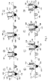
- Figure 2 is a series of views depicting several configurations for the attachment means.
- the attachment means comprises at its bottom end a plurality of faces, which are pressed into the membrane to attach it to the flange of the capsule body over a plurality of regions corresponding to said faces.
- Figure 2A and 2B depict an orthogonal view and a perspective view, respectively, of an attachment means 200.
- the attachment means 200 is substantially in the form of a hollow cylinder.
- Two slots 201 have been provided in the attachment means 200, with the result that the end of the attachment means 200 is divided into two faces 202 and two voids 203.
- the membrane When pressed into a membrane during the attachment step as described above, the membrane will be attached to a flange of a capsule body over the portion of the surface of the flange corresponding to the faces 202 of a first kind.
- the membrane will remain unattached and permit fluid communication between the cavity of the capsule body and the surrounding atmosphere through the unattached regions between the membrane and flange defined by the voids 203 of a first kind.
- Figure 2C depicts an orthogonal view of an alternate configuration for the attachment means, comprising four faces 204 of a second kind and four voids 205 of a second kind.
- Such an attachment means will attach a membrane to a flange of a capsule body over a plurality of regions corresponding to each of the four faces 204 of a second kind, while leaving the regions of the membrane corresponding to the four voids 205 of a second kind unattached.
- Figure 2D depicts an orthogonal view of another alternate configuration for the attachment means, provided with eight faces 206 of a third kind and separated by eight voids 207 of a third kind.
- the faces 206 of a third kind will define the region over which a membrane is attached to the flange of a capsule body, and the voids 207 of a third kind defining where it is unattached.
- Figure 2E depicts an orthogonal view of another alternate configuration for the attachment means, provided with eight faces 208 of a fourth kind which are separated by eight voids 209 of a fourth kind.
- the faces 208 of a fourth kind are much smaller than the faces 206 of a third kind, while the voids 209 of a fourth kind are much larger than the voids 207 of a third kind.
- the proportion of the flange of a capsule body to which a membrane will be attached by the attachment device in Figure 2E is much lower than would be achieved by the attachment device of Figure 2D , with a corresponding increase in the size of the regions of the flange to which the membrane remains unattached.
- attachment devices may in this way be configured to best suit the particular application in which the attachment device is to be employed.
- the attachment devices are altered by adjusting their number and size; however, in other embodiments it may be advantageous to modify other elements of their form and geometry such as shape, thickness, or placement about the lower end of the attachment means.
- the attachment means may reduce the time required to apply the vacuum to the capsule body while still minimizing the aspiration and entrainment of the coffee powder or other edible granules contained within the capsule body.
- the sealing of the beverage capsules may thus be optimized to achieve a maximum output at a minimum cost.
- FIG. 3 is a flowchart depicting a process for the fabrication of beverage capsules, said operation comprising a series of elements.
- the first step of the operation is Capsule Body Destacking 300.
- the empty capsule bodies are generally stored stacked atop each other when stored before use, and so must be separated before they can be further processed.
- the capsule bodies are separated from each other and placed in the proper orientation to continue in the process.
- the Coffee Preparation Process 301 furnishes a supply of coffee powder for packaging within the beverage capsules.
- coffee beans are roasted to the desired degree of roasting and then ground to the desired degree of fineness.
- the gases generated within the coffee beans during roasting are evolved from the coffee. Some degassing will occur between the roasting of the coffee and the sealing of the beverage capsule. It is preferable, however, to configure the process for fabrication of beverage capsules to minimize degassing outside of the capsule, so that the degassing essentially occurs after the beverage capsule has been sealed.
- the duration between the grinding of the coffee and its provision within the beverage capsule is less than ten minutes; in this way the flavor and aroma of the beverage ultimately produced from the beverage capsule is best preserved.
- a portion of the coffee powder provided by the Coffee Preparation Process 301 is placed within the capsule body and densified, so that the coffee is settled within the capsule body and the amount of gas therein is so minimized.
- the beverage powder may be compacted into a tablet during the Coffee Preparation Process 301 step, which is then positioned in the capsule body during the step of Product Filling & Densifying 302.
- each element of the operation is linked by a step for Transport 303, where the capsule body is transferred between the devices for carrying out each element of the operation.
- the elements for carrying out each of the elements of the process may be located in proximity to each other, or even integrated into each other, so that the time required for transporting the beverage capsule between elements is minimized. The process is thereby rendered more space-efficient and economical.
- Membrane Attachment and Cutting 305 is attached to the flange of the capsule body at a plurality of regions of the flange, leaving a plurality of unsealed regions on said flange as well.
- the membrane is also cut to a size which will cover the flange and open end of the capsule body.
- Vacuum Application & Sealing 306 depicted in Figure 1 , Views E-H.
- a vacuum is applied to the capsule body, removing the gasfrom within through the plurality of unsealed regions of the flange.
- the membrane is then sealed over the entirety of the surface of the flange, preserving the vacuum within the capsule.
- the vacuum within the capsule is a reduction of pressure high enough to offset the pressure generated by the gases evolved by the coffee as it degasses in the capsule.
- a normally configured beverage capsule will so resist the pressure accumulated within the sealed capsule as a result of the evolved gases.
- the capsule is transferred to Distribution 308, where it may be packaged in a box, sleeve, bag, or the like and distributed for sale.
- the present invention may be adapted to fabricate beverage capsules for the preparation of various kinds of alimentary substances, for example broth, cocoa, coffee, infant formula, milk, tea, tisane or any combination thereof.
- the edible granules comprising said alimentary substances may be provided in various forms and sizes, such as flakes, grains, granules, pellets, powders, shreds, or any combination thereof. While the particular embodiment of the preceding description is directed to a beverage capsule containing a quantity of roasted, powdered coffee, it should not be construed as limiting the scope of the invention to beverage capsules so configured.
Landscapes
- Engineering & Computer Science (AREA)
- Mechanical Engineering (AREA)
- Chemical & Material Sciences (AREA)
- Dispersion Chemistry (AREA)
- Apparatus For Making Beverages (AREA)
- Vacuum Packaging (AREA)
- Packages (AREA)
- Closing Of Containers (AREA)
- Package Closures (AREA)
Priority Applications (1)
| Application Number | Priority Date | Filing Date | Title |
|---|---|---|---|
| EP13730601.5A EP2870069B1 (en) | 2012-07-04 | 2013-06-25 | Method and apparatus for fabricating a beverage capsule |
Applications Claiming Priority (3)
| Application Number | Priority Date | Filing Date | Title |
|---|---|---|---|
| EP12174912 | 2012-07-04 | ||
| PCT/EP2013/063174 WO2014005872A1 (en) | 2012-07-04 | 2013-06-25 | Method and apparatus for fabricating a beverage capsule |
| EP13730601.5A EP2870069B1 (en) | 2012-07-04 | 2013-06-25 | Method and apparatus for fabricating a beverage capsule |
Publications (2)
| Publication Number | Publication Date |
|---|---|
| EP2870069A1 EP2870069A1 (en) | 2015-05-13 |
| EP2870069B1 true EP2870069B1 (en) | 2016-08-31 |
Family
ID=48670587
Family Applications (1)
| Application Number | Title | Priority Date | Filing Date |
|---|---|---|---|
| EP13730601.5A Active EP2870069B1 (en) | 2012-07-04 | 2013-06-25 | Method and apparatus for fabricating a beverage capsule |
Country Status (16)
| Country | Link |
|---|---|
| US (1) | US20150225099A1 (es) |
| EP (1) | EP2870069B1 (es) |
| JP (1) | JP2015527261A (es) |
| KR (1) | KR20150034235A (es) |
| CN (1) | CN104395194B (es) |
| AR (1) | AR099245A1 (es) |
| AU (1) | AU2013286097A1 (es) |
| BR (1) | BR112014030477A2 (es) |
| CA (1) | CA2875326A1 (es) |
| ES (1) | ES2593352T3 (es) |
| IL (1) | IL235872A0 (es) |
| IN (1) | IN2014DN10126A (es) |
| MX (1) | MX2014014954A (es) |
| PT (1) | PT2870069T (es) |
| RU (1) | RU2015103514A (es) |
| WO (1) | WO2014005872A1 (es) |
Families Citing this family (15)
| Publication number | Priority date | Publication date | Assignee | Title |
|---|---|---|---|---|
| EP2730523B1 (en) * | 2012-11-12 | 2016-04-06 | 2266170 Ontario, Inc. | Beverage capsule and process and system for making same |
| WO2015118450A1 (en) * | 2014-02-06 | 2015-08-13 | I.M.A. Industria Macchine Automatiche S.P.A. | Unit and method for releasing product for extraction or infusion beverages in containers forming single-use capsules or pods |
| US10442610B2 (en) | 2014-03-11 | 2019-10-15 | Starbucks Corporation | Pod-based restrictors and methods |
| EP3307648B1 (de) | 2015-06-09 | 2020-02-19 | K-fee System GmbH | Portionskapsel, system und verfahren zur herstellung eines getränks |
| AR105231A1 (es) | 2015-06-09 | 2017-09-20 | Cryovac Inc | Aparato y proceso para envasar productos |
| ITUB20152469A1 (it) * | 2015-07-24 | 2017-01-24 | Marco Verri | Apparecchiatura per la realizzazione di un prodotto, preferibilmente di un prodotto alimentare per realizzare una bevanda tramite infusione in un rispettivo liquido |
| ITUB20155347A1 (it) * | 2015-10-30 | 2016-01-30 | Cossa Polimeri S R L | Capsula per la preparazione di bevande ad infusione o solubili. |
| US10472104B2 (en) * | 2016-01-25 | 2019-11-12 | Kurt Allen Jenkins | Method of fabricating coffee pods at point of sale |
| EP3494068B1 (en) * | 2016-08-03 | 2024-04-03 | Société des Produits Nestlé S.A. | Capsule for the preparation of a beverage containing pellets |
| DE102016120786A1 (de) * | 2016-11-01 | 2018-05-03 | Hauni Maschinenbau Gmbh | Kapsel zum Einsetzen in einen Kopf einer Wasserpfeife, Maschine der Tabak verarbeitenden Industrie und Verfahren zum Herstellen einer solchen Kapsel |
| CA3041722A1 (en) | 2016-11-09 | 2018-05-17 | Pepsico, Inc. | Carbonated beverage makers, methods, and systems |
| US10414529B1 (en) | 2018-04-17 | 2019-09-17 | William S. Bayer | Machines and components for generating beverage pods for use in single serve beverage brewing machines |
| IT201900013185A1 (it) * | 2019-07-29 | 2021-01-29 | S A T S R L | Apparato e metodo di chiusura di capsule |
| CN115867498A (zh) * | 2020-07-15 | 2023-03-28 | 雀巢产品有限公司 | 制造用于储存单独的食品或饮料分份的包装条的方法以及因此获得的包装条 |
| CN112758412A (zh) * | 2020-12-22 | 2021-05-07 | 莆田市城厢区诚味食品有限公司 | 一种速冻肉全自动抽氧包装设备 |
Family Cites Families (24)
| Publication number | Priority date | Publication date | Assignee | Title |
|---|---|---|---|---|
| US3077409A (en) * | 1958-07-02 | 1963-02-12 | American Can Co | Coffee package |
| US3218776A (en) * | 1961-09-11 | 1965-11-23 | Cloud Machine Corp | Packaging method and apparatus |
| US4069349A (en) | 1970-06-22 | 1978-01-17 | The Continental Group, Inc. | Process for vacuum packaging of roasted, ground coffee |
| CH520016A (de) | 1971-03-18 | 1972-03-15 | Tourpac Ag | Vorrichtung zur Herstellung von gefüllten evakuierten Packungen und Verfahren zum Betrieb der Vorrichtung |
| US3838550A (en) * | 1972-08-22 | 1974-10-01 | Owens Illinois Inc | Method and apparatus for packaging |
| US4162599A (en) * | 1978-06-19 | 1979-07-31 | C. A. Pemberton & Co. Limited | Vacuum packaging |
| JPS58183407A (ja) * | 1982-04-13 | 1983-10-26 | 押尾産業株式会社 | カツプ状容器のシ−ル方法 |
| JPS6193023A (ja) * | 1984-10-01 | 1986-05-12 | ニツカ株式会社 | 不活性ガス充填包装方法 |
| AU5064285A (en) * | 1984-11-02 | 1986-05-15 | Ingold, F. | Verfahren und vorrichtung zur herstellung eines getrankes, insbesondere kaffee |
| US4571924A (en) * | 1985-04-29 | 1986-02-25 | The Procter & Gamble Company | Method and apparatus of manufacturing porous pouches containing granular product |
| US4736568A (en) * | 1986-09-29 | 1988-04-12 | Rutherford Research, Inc. | Machine for sealing cups |
| US4791775A (en) * | 1987-04-22 | 1988-12-20 | Raque Food Systems, Inc. | Packaging device |
| US4870800A (en) * | 1988-04-05 | 1989-10-03 | Nikka Co., Ltd. | Inert gas-filling and sealing device, heat sealing device and packaging apparatus using these devices |
| DE4192762C2 (de) | 1990-10-31 | 2002-09-19 | Monodor Sa | Apparat und Kapsel zur Herstellung eines flüssigen Produktes |
| US5271207A (en) * | 1992-11-18 | 1993-12-21 | Moshe Epstein | Dual-function nozzle head for vacuum-packaging tooling |
| US5943844A (en) * | 1996-05-31 | 1999-08-31 | Ross Industries, Inc. | Method of wrapping a food product, packaging machine used and package formed |
| US5718101A (en) * | 1996-06-04 | 1998-02-17 | W. R. Grace & Co.-Conn. | Method and apparatus for packaging a product in a dual-lid package |
| US6351928B2 (en) * | 1996-12-17 | 2002-03-05 | Minipack Torre S.P.A. | Device for packaging products in containers sealed with stretchable plastic film |
| ATE215471T1 (de) * | 1997-10-06 | 2002-04-15 | Rossi Jean Pierre | Vorrichtung zum konditionieren in einer kontrollierten atmosphäre von produkten in mit einer folie versiegelten behältern |
| US6202388B1 (en) * | 1998-11-06 | 2001-03-20 | Jescorp, Inc. | Controlled environment sealing apparatus and method |
| DE102005015399B3 (de) | 2005-04-04 | 2006-05-18 | Klaus Bruchmann | Schaltersicherungseinheit |
| ITBO20070303A1 (it) * | 2007-04-24 | 2008-10-25 | Aroma System Srl Gino | Macchina per il confezionamento di capsule anche sotto vuoto e/o in atmosfera controllata |
| EP2310273B1 (en) | 2008-07-14 | 2013-02-20 | Gima S.P.A. | Machine for packaging products, in particular capsules for machines for delivering infusion beverages |
| IT1396122B1 (it) * | 2009-10-02 | 2012-11-16 | Conti | Metodo e macchina per il confezionamento di capsule con prodotti da infusione. |
-
2013
- 2013-06-25 IN IN10126DEN2014 patent/IN2014DN10126A/en unknown
- 2013-06-25 BR BR112014030477A patent/BR112014030477A2/pt not_active IP Right Cessation
- 2013-06-25 MX MX2014014954A patent/MX2014014954A/es unknown
- 2013-06-25 CN CN201380034643.1A patent/CN104395194B/zh not_active Expired - Fee Related
- 2013-06-25 AU AU2013286097A patent/AU2013286097A1/en not_active Abandoned
- 2013-06-25 ES ES13730601.5T patent/ES2593352T3/es active Active
- 2013-06-25 PT PT137306015T patent/PT2870069T/pt unknown
- 2013-06-25 EP EP13730601.5A patent/EP2870069B1/en active Active
- 2013-06-25 RU RU2015103514A patent/RU2015103514A/ru not_active Application Discontinuation
- 2013-06-25 JP JP2015519028A patent/JP2015527261A/ja active Pending
- 2013-06-25 KR KR20157002783A patent/KR20150034235A/ko not_active Application Discontinuation
- 2013-06-25 WO PCT/EP2013/063174 patent/WO2014005872A1/en active Application Filing
- 2013-06-25 US US14/411,963 patent/US20150225099A1/en not_active Abandoned
- 2013-06-25 CA CA2875326A patent/CA2875326A1/en not_active Abandoned
- 2013-07-04 AR ARP130102391A patent/AR099245A1/es unknown
-
2014
- 2014-11-24 IL IL235872A patent/IL235872A0/en unknown
Also Published As
| Publication number | Publication date |
|---|---|
| BR112014030477A2 (pt) | 2017-06-27 |
| KR20150034235A (ko) | 2015-04-02 |
| WO2014005872A1 (en) | 2014-01-09 |
| IL235872A0 (en) | 2015-01-29 |
| CN104395194B (zh) | 2016-10-19 |
| PT2870069T (pt) | 2016-11-14 |
| CA2875326A1 (en) | 2014-01-09 |
| EP2870069A1 (en) | 2015-05-13 |
| US20150225099A1 (en) | 2015-08-13 |
| MX2014014954A (es) | 2015-03-09 |
| AU2013286097A1 (en) | 2014-12-18 |
| CN104395194A (zh) | 2015-03-04 |
| AR099245A1 (es) | 2016-07-13 |
| JP2015527261A (ja) | 2015-09-17 |
| IN2014DN10126A (es) | 2015-08-21 |
| RU2015103514A (ru) | 2016-08-20 |
| ES2593352T3 (es) | 2016-12-07 |
Similar Documents
| Publication | Publication Date | Title |
|---|---|---|
| EP2870069B1 (en) | Method and apparatus for fabricating a beverage capsule | |
| AU2013286098B2 (en) | Method for packaging a beverage powder in a beverage capsule | |
| EP2730523B1 (en) | Beverage capsule and process and system for making same | |
| RU2494935C1 (ru) | Вакуум-формованное упаковывание помещающегося на подложке продукта в плотно прилегающую пленку | |
| CN101687556B (zh) | 用于在真空和/或受控气氛中包装容器的设备 | |
| EP1966060B1 (en) | Beverage preparation capsules | |
| KR100189384B1 (ko) | 개방되고 가요성있는 포장용기 및 그 제조방법 | |
| EP1956921B1 (en) | Process for preparing coffee tablets by aid of ultrasound | |
| EP3611101B1 (en) | Packaging machine for making a package which includes a bag of flexible material filled with a dose of liquid or semi-liquid product | |
| EP3325348B1 (en) | Apparatus for making a food product for making a drink by infusion in a respective liquid | |
| US4069349A (en) | Process for vacuum packaging of roasted, ground coffee | |
| WO2021122678A1 (en) | Package for storing individual portion of beverage precursor for preparing a beverage therefrom, strip of such packages, and system comprising a beverage preparation apparatus and at least such a package | |
| US5351463A (en) | Method and apparatus for making a filled and closed vacuum pak | |
| JP2009012858A (ja) | 加工食品の複数列式真空連続包装装置 | |
| EP3795482A1 (en) | Beverage capsule manufacture | |
| EP2188182A2 (en) | Container, method and apparatus for packaging products | |
| JPH07267205A (ja) | ガス発生物質の連続包装方法 | |
| AU7942798A (en) | Package and packaging method | |
| EP1615834A1 (en) | Liquid-trapping bag and method of making it |
Legal Events
| Date | Code | Title | Description |
|---|---|---|---|
| PUAI | Public reference made under article 153(3) epc to a published international application that has entered the european phase |
Free format text: ORIGINAL CODE: 0009012 |
|
| 17P | Request for examination filed |
Effective date: 20150204 |
|
| AK | Designated contracting states |
Kind code of ref document: A1 Designated state(s): AL AT BE BG CH CY CZ DE DK EE ES FI FR GB GR HR HU IE IS IT LI LT LU LV MC MK MT NL NO PL PT RO RS SE SI SK SM TR |
|
| AX | Request for extension of the european patent |
Extension state: BA ME |
|
| DAX | Request for extension of the european patent (deleted) | ||
| GRAP | Despatch of communication of intention to grant a patent |
Free format text: ORIGINAL CODE: EPIDOSNIGR1 |
|
| INTG | Intention to grant announced |
Effective date: 20160513 |
|
| GRAS | Grant fee paid |
Free format text: ORIGINAL CODE: EPIDOSNIGR3 |
|
| GRAA | (expected) grant |
Free format text: ORIGINAL CODE: 0009210 |
|
| AK | Designated contracting states |
Kind code of ref document: B1 Designated state(s): AL AT BE BG CH CY CZ DE DK EE ES FI FR GB GR HR HU IE IS IT LI LT LU LV MC MK MT NL NO PL PT RO RS SE SI SK SM TR |
|
| REG | Reference to a national code |
Ref country code: CH Ref legal event code: EP Ref country code: GB Ref legal event code: FG4D |
|
| REG | Reference to a national code |
Ref country code: IE Ref legal event code: FG4D |
|
| REG | Reference to a national code |
Ref country code: DE Ref legal event code: R096 Ref document number: 602013010904 Country of ref document: DE |
|
| REG | Reference to a national code |
Ref country code: AT Ref legal event code: REF Ref document number: 824739 Country of ref document: AT Kind code of ref document: T Effective date: 20161015 |
|
| REG | Reference to a national code |
Ref country code: PT Ref legal event code: SC4A Ref document number: 2870069 Country of ref document: PT Date of ref document: 20161114 Kind code of ref document: T Free format text: AVAILABILITY OF NATIONAL TRANSLATION Effective date: 20161107 |
|
| REG | Reference to a national code |
Ref country code: NL Ref legal event code: FP |
|
| REG | Reference to a national code |
Ref country code: ES Ref legal event code: FG2A Ref document number: 2593352 Country of ref document: ES Kind code of ref document: T3 Effective date: 20161207 |
|
| REG | Reference to a national code |
Ref country code: LT Ref legal event code: MG4D |
|
| PG25 | Lapsed in a contracting state [announced via postgrant information from national office to epo] |
Ref country code: NO Free format text: LAPSE BECAUSE OF FAILURE TO SUBMIT A TRANSLATION OF THE DESCRIPTION OR TO PAY THE FEE WITHIN THE PRESCRIBED TIME-LIMIT Effective date: 20161130 Ref country code: RS Free format text: LAPSE BECAUSE OF FAILURE TO SUBMIT A TRANSLATION OF THE DESCRIPTION OR TO PAY THE FEE WITHIN THE PRESCRIBED TIME-LIMIT Effective date: 20160831 Ref country code: LT Free format text: LAPSE BECAUSE OF FAILURE TO SUBMIT A TRANSLATION OF THE DESCRIPTION OR TO PAY THE FEE WITHIN THE PRESCRIBED TIME-LIMIT Effective date: 20160831 Ref country code: HR Free format text: LAPSE BECAUSE OF FAILURE TO SUBMIT A TRANSLATION OF THE DESCRIPTION OR TO PAY THE FEE WITHIN THE PRESCRIBED TIME-LIMIT Effective date: 20160831 Ref country code: FI Free format text: LAPSE BECAUSE OF FAILURE TO SUBMIT A TRANSLATION OF THE DESCRIPTION OR TO PAY THE FEE WITHIN THE PRESCRIBED TIME-LIMIT Effective date: 20160831 |
|
| PG25 | Lapsed in a contracting state [announced via postgrant information from national office to epo] |
Ref country code: GR Free format text: LAPSE BECAUSE OF FAILURE TO SUBMIT A TRANSLATION OF THE DESCRIPTION OR TO PAY THE FEE WITHIN THE PRESCRIBED TIME-LIMIT Effective date: 20161201 Ref country code: SE Free format text: LAPSE BECAUSE OF FAILURE TO SUBMIT A TRANSLATION OF THE DESCRIPTION OR TO PAY THE FEE WITHIN THE PRESCRIBED TIME-LIMIT Effective date: 20160831 Ref country code: LV Free format text: LAPSE BECAUSE OF FAILURE TO SUBMIT A TRANSLATION OF THE DESCRIPTION OR TO PAY THE FEE WITHIN THE PRESCRIBED TIME-LIMIT Effective date: 20160831 |
|
| PG25 | Lapsed in a contracting state [announced via postgrant information from national office to epo] |
Ref country code: RO Free format text: LAPSE BECAUSE OF FAILURE TO SUBMIT A TRANSLATION OF THE DESCRIPTION OR TO PAY THE FEE WITHIN THE PRESCRIBED TIME-LIMIT Effective date: 20160831 Ref country code: EE Free format text: LAPSE BECAUSE OF FAILURE TO SUBMIT A TRANSLATION OF THE DESCRIPTION OR TO PAY THE FEE WITHIN THE PRESCRIBED TIME-LIMIT Effective date: 20160831 |
|
| REG | Reference to a national code |
Ref country code: FR Ref legal event code: PLFP Year of fee payment: 5 |
|
| PG25 | Lapsed in a contracting state [announced via postgrant information from national office to epo] |
Ref country code: PL Free format text: LAPSE BECAUSE OF FAILURE TO SUBMIT A TRANSLATION OF THE DESCRIPTION OR TO PAY THE FEE WITHIN THE PRESCRIBED TIME-LIMIT Effective date: 20160831 Ref country code: SM Free format text: LAPSE BECAUSE OF FAILURE TO SUBMIT A TRANSLATION OF THE DESCRIPTION OR TO PAY THE FEE WITHIN THE PRESCRIBED TIME-LIMIT Effective date: 20160831 Ref country code: CZ Free format text: LAPSE BECAUSE OF FAILURE TO SUBMIT A TRANSLATION OF THE DESCRIPTION OR TO PAY THE FEE WITHIN THE PRESCRIBED TIME-LIMIT Effective date: 20160831 Ref country code: DK Free format text: LAPSE BECAUSE OF FAILURE TO SUBMIT A TRANSLATION OF THE DESCRIPTION OR TO PAY THE FEE WITHIN THE PRESCRIBED TIME-LIMIT Effective date: 20160831 Ref country code: SK Free format text: LAPSE BECAUSE OF FAILURE TO SUBMIT A TRANSLATION OF THE DESCRIPTION OR TO PAY THE FEE WITHIN THE PRESCRIBED TIME-LIMIT Effective date: 20160831 Ref country code: BG Free format text: LAPSE BECAUSE OF FAILURE TO SUBMIT A TRANSLATION OF THE DESCRIPTION OR TO PAY THE FEE WITHIN THE PRESCRIBED TIME-LIMIT Effective date: 20161130 |
|
| REG | Reference to a national code |
Ref country code: DE Ref legal event code: R097 Ref document number: 602013010904 Country of ref document: DE |
|
| PLBE | No opposition filed within time limit |
Free format text: ORIGINAL CODE: 0009261 |
|
| STAA | Information on the status of an ep patent application or granted ep patent |
Free format text: STATUS: NO OPPOSITION FILED WITHIN TIME LIMIT |
|
| PGFP | Annual fee paid to national office [announced via postgrant information from national office to epo] |
Ref country code: GB Payment date: 20170621 Year of fee payment: 5 |
|
| 26N | No opposition filed |
Effective date: 20170601 |
|
| PG25 | Lapsed in a contracting state [announced via postgrant information from national office to epo] |
Ref country code: SI Free format text: LAPSE BECAUSE OF FAILURE TO SUBMIT A TRANSLATION OF THE DESCRIPTION OR TO PAY THE FEE WITHIN THE PRESCRIBED TIME-LIMIT Effective date: 20160831 |
|
| PGFP | Annual fee paid to national office [announced via postgrant information from national office to epo] |
Ref country code: RO Payment date: 20170728 Year of fee payment: 10 Ref country code: BE Payment date: 20170424 Year of fee payment: 5 |
|
| PGFP | Annual fee paid to national office [announced via postgrant information from national office to epo] |
Ref country code: TR Payment date: 20170531 Year of fee payment: 5 |
|
| PGFP | Annual fee paid to national office [announced via postgrant information from national office to epo] |
Ref country code: ES Payment date: 20170704 Year of fee payment: 5 |
|
| PG25 | Lapsed in a contracting state [announced via postgrant information from national office to epo] |
Ref country code: MC Free format text: LAPSE BECAUSE OF FAILURE TO SUBMIT A TRANSLATION OF THE DESCRIPTION OR TO PAY THE FEE WITHIN THE PRESCRIBED TIME-LIMIT Effective date: 20160831 |
|
| REG | Reference to a national code |
Ref country code: IE Ref legal event code: MM4A |
|
| PG25 | Lapsed in a contracting state [announced via postgrant information from national office to epo] |
Ref country code: IE Free format text: LAPSE BECAUSE OF NON-PAYMENT OF DUE FEES Effective date: 20170625 Ref country code: LU Free format text: LAPSE BECAUSE OF NON-PAYMENT OF DUE FEES Effective date: 20170625 |
|
| REG | Reference to a national code |
Ref country code: FR Ref legal event code: PLFP Year of fee payment: 6 |
|
| PG25 | Lapsed in a contracting state [announced via postgrant information from national office to epo] |
Ref country code: MT Free format text: LAPSE BECAUSE OF NON-PAYMENT OF DUE FEES Effective date: 20170625 |
|
| PG25 | Lapsed in a contracting state [announced via postgrant information from national office to epo] |
Ref country code: AL Free format text: LAPSE BECAUSE OF FAILURE TO SUBMIT A TRANSLATION OF THE DESCRIPTION OR TO PAY THE FEE WITHIN THE PRESCRIBED TIME-LIMIT Effective date: 20160831 |
|
| PG25 | Lapsed in a contracting state [announced via postgrant information from national office to epo] |
Ref country code: PT Free format text: LAPSE BECAUSE OF NON-PAYMENT OF DUE FEES Effective date: 20181226 |
|
| GBPC | Gb: european patent ceased through non-payment of renewal fee |
Effective date: 20180625 |
|
| REG | Reference to a national code |
Ref country code: BE Ref legal event code: FP Effective date: 20161124 Ref country code: BE Ref legal event code: MM Effective date: 20180630 |
|
| REG | Reference to a national code |
Ref country code: AT Ref legal event code: UEP Ref document number: 824739 Country of ref document: AT Kind code of ref document: T Effective date: 20160831 |
|
| PG25 | Lapsed in a contracting state [announced via postgrant information from national office to epo] |
Ref country code: GB Free format text: LAPSE BECAUSE OF NON-PAYMENT OF DUE FEES Effective date: 20180625 |
|
| PG25 | Lapsed in a contracting state [announced via postgrant information from national office to epo] |
Ref country code: BE Free format text: LAPSE BECAUSE OF NON-PAYMENT OF DUE FEES Effective date: 20180630 |
|
| PG25 | Lapsed in a contracting state [announced via postgrant information from national office to epo] |
Ref country code: HU Free format text: LAPSE BECAUSE OF FAILURE TO SUBMIT A TRANSLATION OF THE DESCRIPTION OR TO PAY THE FEE WITHIN THE PRESCRIBED TIME-LIMIT; INVALID AB INITIO Effective date: 20130625 |
|
| REG | Reference to a national code |
Ref country code: NL Ref legal event code: PD Owner name: SOCIETE DES PRODUITS NESTLE S.A.; CH Free format text: DETAILS ASSIGNMENT: CHANGE OF OWNER(S), MERGE; FORMER OWNER NAME: NESTEC S.A. Effective date: 20190620 |
|
| REG | Reference to a national code |
Ref country code: CH Ref legal event code: PFUS Owner name: SOCIETE DES PRODUITS NESTLE S.A., CH Free format text: FORMER OWNER: NESTEC S.A., CH |
|
| REG | Reference to a national code |
Ref country code: AT Ref legal event code: MM01 Ref document number: 824739 Country of ref document: AT Kind code of ref document: T Effective date: 20180625 |
|
| REG | Reference to a national code |
Ref country code: ES Ref legal event code: FD2A Effective date: 20190916 |
|
| PG25 | Lapsed in a contracting state [announced via postgrant information from national office to epo] |
Ref country code: ES Free format text: LAPSE BECAUSE OF NON-PAYMENT OF DUE FEES Effective date: 20180626 Ref country code: CY Free format text: LAPSE BECAUSE OF FAILURE TO SUBMIT A TRANSLATION OF THE DESCRIPTION OR TO PAY THE FEE WITHIN THE PRESCRIBED TIME-LIMIT Effective date: 20160831 |
|
| PG25 | Lapsed in a contracting state [announced via postgrant information from national office to epo] |
Ref country code: MK Free format text: LAPSE BECAUSE OF FAILURE TO SUBMIT A TRANSLATION OF THE DESCRIPTION OR TO PAY THE FEE WITHIN THE PRESCRIBED TIME-LIMIT Effective date: 20160831 |
|
| PG25 | Lapsed in a contracting state [announced via postgrant information from national office to epo] |
Ref country code: AT Free format text: LAPSE BECAUSE OF NON-PAYMENT OF DUE FEES Effective date: 20180625 |
|
| REG | Reference to a national code |
Ref country code: DE Ref legal event code: R082 Ref document number: 602013010904 Country of ref document: DE Representative=s name: MITSCHERLICH, PATENT- UND RECHTSANWAELTE PARTM, DE Ref country code: DE Ref legal event code: R081 Ref document number: 602013010904 Country of ref document: DE Owner name: SOCIETE DES PRODUITS NESTLE S.A., CH Free format text: FORMER OWNER: NESTEC S.A., VEVEY, CH |
|
| PG25 | Lapsed in a contracting state [announced via postgrant information from national office to epo] |
Ref country code: IS Free format text: LAPSE BECAUSE OF FAILURE TO SUBMIT A TRANSLATION OF THE DESCRIPTION OR TO PAY THE FEE WITHIN THE PRESCRIBED TIME-LIMIT Effective date: 20161231 |
|
| PGFP | Annual fee paid to national office [announced via postgrant information from national office to epo] |
Ref country code: NL Payment date: 20200615 Year of fee payment: 8 Ref country code: IT Payment date: 20200512 Year of fee payment: 8 |
|
| REG | Reference to a national code |
Ref country code: NL Ref legal event code: MM Effective date: 20210701 |
|
| PG25 | Lapsed in a contracting state [announced via postgrant information from national office to epo] |
Ref country code: NL Free format text: LAPSE BECAUSE OF NON-PAYMENT OF DUE FEES Effective date: 20210701 |
|
| PG25 | Lapsed in a contracting state [announced via postgrant information from national office to epo] |
Ref country code: TR Free format text: LAPSE BECAUSE OF NON-PAYMENT OF DUE FEES Effective date: 20180625 |
|
| PG25 | Lapsed in a contracting state [announced via postgrant information from national office to epo] |
Ref country code: IT Free format text: LAPSE BECAUSE OF NON-PAYMENT OF DUE FEES Effective date: 20210625 |
|
| P01 | Opt-out of the competence of the unified patent court (upc) registered |
Effective date: 20230527 |
|
| PGFP | Annual fee paid to national office [announced via postgrant information from national office to epo] |
Ref country code: FR Payment date: 20230510 Year of fee payment: 11 Ref country code: DE Payment date: 20230502 Year of fee payment: 11 |
|
| PGFP | Annual fee paid to national office [announced via postgrant information from national office to epo] |
Ref country code: CH Payment date: 20230702 Year of fee payment: 11 |