EP2869955B1 - Beveling cutter having helical edged blades and discharge grooves - Google Patents
Beveling cutter having helical edged blades and discharge grooves Download PDFInfo
- Publication number
- EP2869955B1 EP2869955B1 EP13742534.4A EP13742534A EP2869955B1 EP 2869955 B1 EP2869955 B1 EP 2869955B1 EP 13742534 A EP13742534 A EP 13742534A EP 2869955 B1 EP2869955 B1 EP 2869955B1
- Authority
- EP
- European Patent Office
- Prior art keywords
- cutter
- beveling
- angle
- degrees
- blades
- Prior art date
- Legal status (The legal status is an assumption and is not a legal conclusion. Google has not performed a legal analysis and makes no representation as to the accuracy of the status listed.)
- Active
Links
Images
Classifications
-
- B—PERFORMING OPERATIONS; TRANSPORTING
- B23—MACHINE TOOLS; METAL-WORKING NOT OTHERWISE PROVIDED FOR
- B23C—MILLING
- B23C3/00—Milling particular work; Special milling operations; Machines therefor
- B23C3/12—Trimming or finishing edges, e.g. deburring welded corners
- B23C3/126—Portable devices or machines for chamfering edges
-
- B—PERFORMING OPERATIONS; TRANSPORTING
- B23—MACHINE TOOLS; METAL-WORKING NOT OTHERWISE PROVIDED FOR
- B23C—MILLING
- B23C3/00—Milling particular work; Special milling operations; Machines therefor
- B23C3/12—Trimming or finishing edges, e.g. deburring welded corners
-
- B—PERFORMING OPERATIONS; TRANSPORTING
- B23—MACHINE TOOLS; METAL-WORKING NOT OTHERWISE PROVIDED FOR
- B23C—MILLING
- B23C1/00—Milling machines not designed for particular work or special operations
- B23C1/20—Portable devices or machines; Hand-driven devices or machines
-
- B—PERFORMING OPERATIONS; TRANSPORTING
- B23—MACHINE TOOLS; METAL-WORKING NOT OTHERWISE PROVIDED FOR
- B23C—MILLING
- B23C5/00—Milling-cutters
- B23C5/02—Milling-cutters characterised by the shape of the cutter
- B23C5/04—Plain cutters, i.e. having essentially a cylindrical or tapered cutting surface of substantial length
-
- B—PERFORMING OPERATIONS; TRANSPORTING
- B23—MACHINE TOOLS; METAL-WORKING NOT OTHERWISE PROVIDED FOR
- B23C—MILLING
- B23C5/00—Milling-cutters
- B23C5/02—Milling-cutters characterised by the shape of the cutter
- B23C5/12—Cutters specially designed for producing particular profiles
-
- B—PERFORMING OPERATIONS; TRANSPORTING
- B23—MACHINE TOOLS; METAL-WORKING NOT OTHERWISE PROVIDED FOR
- B23C—MILLING
- B23C2210/00—Details of milling cutters
- B23C2210/04—Angles
-
- B—PERFORMING OPERATIONS; TRANSPORTING
- B23—MACHINE TOOLS; METAL-WORKING NOT OTHERWISE PROVIDED FOR
- B23C—MILLING
- B23C2210/00—Details of milling cutters
- B23C2210/04—Angles
- B23C2210/0485—Helix angles
-
- B—PERFORMING OPERATIONS; TRANSPORTING
- B23—MACHINE TOOLS; METAL-WORKING NOT OTHERWISE PROVIDED FOR
- B23C—MILLING
- B23C2210/00—Details of milling cutters
- B23C2210/12—Cross section of the cutting edge
- B23C2210/123—Bevelled cutting edges
-
- B—PERFORMING OPERATIONS; TRANSPORTING
- B23—MACHINE TOOLS; METAL-WORKING NOT OTHERWISE PROVIDED FOR
- B23C—MILLING
- B23C2210/00—Details of milling cutters
- B23C2210/20—Number of cutting edges
- B23C2210/208—Number of cutting edges ten
-
- B—PERFORMING OPERATIONS; TRANSPORTING
- B23—MACHINE TOOLS; METAL-WORKING NOT OTHERWISE PROVIDED FOR
- B23C—MILLING
- B23C2220/00—Details of milling processes
- B23C2220/16—Chamferring
-
- B—PERFORMING OPERATIONS; TRANSPORTING
- B23—MACHINE TOOLS; METAL-WORKING NOT OTHERWISE PROVIDED FOR
- B23C—MILLING
- B23C2265/00—Details of general geometric configurations
- B23C2265/08—Conical
Definitions
- the present invention relates to a beveling cutter according to the preamble of claim 1 capable of machining a beveled edge on metal using helical shaped cutting blades and discharge grooves which can machine an edge on a metal work piece with more uniformity while eliminating vibration and chattering often experienced when beveling metal with traditional tools.
- Such a beveling cutter is known from KR 2010 0093020 A .
- the beveling machines of the related art include a drive unit and a power transmission unit in a main body having the function of a handle with a spindle mounted on a head unit, which spindle is rotated by power from the power transmission unit.
- the beveling cutter is mounted on the free end of the spindle.
- a base or guide plate is installed between the spindle and the power transmission unit which serves as a depth guide on one side of the bevel.
- a cam bearing is attached over the top of the beveling cutter which serves as a depth guide on the opposite side of the bevel.
- the edge of a work piece is aligned with the cutter, the driving unit in the body is driven by an electric or a pneumatic motor, and the driving force rotates the spindle through the power transmission unit. With the rotation of the spindle, the router bit at the free end is rotated and machines a predetermined shape on the work piece.
- the beveling cutter disclosed in an embodiment includes a body with a shaft hole formed through the center, a plurality of ten (10) cutter blades extending at regular intervals with a helix angle of 1 to 40 degrees around the shaft hole on the outer circumferential surface of the body while having both sides that are beveling sides, discharge grooves formed longitudinally between the cutter blades to discharge chips produced in beveling, and cutting grooves recessed on the surfaces of the cutter blades.
- a body with a shaft hole formed through the center
- a plurality of ten (10) cutter blades extending at regular intervals with a helix angle of 1 to 40 degrees around the shaft hole on the outer circumferential surface of the body while having both sides that are beveling sides, discharge grooves formed longitudinally between the cutter blades to discharge chips produced in beveling, and cutting grooves recessed on the surfaces of the cutter blades.
- one objective of the present invention is to provide a beveling cutter that can machine a metal surface to a uniform shape and finish with uniform roughness when beveling a work piece.
- Another objective of the present invention is to provide a beveling cutter that can easily discharge chips and scrap originating from the beveling process without generating flames when discharging.
- Another objective of the present invention is to provide a beveling cutter that can prevent damage to cutter blades and reduce load in beveling.
- the beveling cutter includes: a body with a shaft hole formed through the center; a plurality of cutter blades arranged at predetermined distances on the circumferential surface of the body, each having a radial primary blade with a radial primary relief angle ranging from 5 to 15 degrees and a radial secondary blade with a radial secondary relief angle ranging from 16 to 30 degrees; discharge grooves formed longitudinally between the cutter blades to discharge chips produced in beveling; and a key groove formed at a portion inside the body.
- Rake angle portions may be formed at an angle ranging from 10 to 20 degrees on a plurality of the cutter blades.
- Helical shape cutter blades may have a core taper angle ranging from 20 to 30 degrees.
- Honed portions may be formed by honing a side of the radial primary blades at an angle ranging from 1 to 45 degrees to prevent the cutter blades from breaking or chattering.
- a beveling cutter such as that in the present invention, since the radial primary relief angle and the radial secondary relief angle range from 5 to 15 degrees and from 16 to 30 degrees, respectively, there are advantages in that it is possible to reduce load generated in the beveling of a work piece and to prevent machining interference and chattering by ensuring a sufficient gap between the work piece and the radial primary blades.
- a beveling cutter such as that in an embodiment, since the honed portion is formed at a side of the radial primary blade, there is the advantage in that it is possible to prevent the cutter blades from breaking and chattering. Further, since the core taper angle of the beveling cutter ranges from 20 to 30 degrees, there is the advantage in that it is possible to increase the stiffness and lifespan of the beveling cutter.
- rake angle portions are formed in the range of angle of 10 to 20 degrees, there is also the advantage in that it is possible to smoothly discharge chips produced in beveling of a work piece, even without specific cutting grooves.
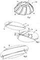
- FIG. 1 is a perspective view showing a beveling cutter according to an embodiment of the present invention
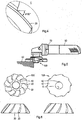
- FIG. 2 is a view illustrating radial primary and secondary relief angles of a cutter blade that is a main part of the present invention
- FIG. 3 is a view illustrating a core taper of a cutter blade that is a main part of the present invention
- FIG. 4 is a side view illustrating a helix angle of a cutter blade that is a main part of the present invention.
- Beveling cutter 100 in the form of an embodiment of the present invention includes a body 10, a plurality of cutter blades 20 arranged at predetermined distances on the circumferential surface of the body 10, discharge grooves 30 formed longitudinally between the cutter blades 20 to discharge chips produced in beveling, and a key groove 40 formed at a portion inside the body 10.
- the body 10 of the beveling cutter 100 has a shaft hole 5 formed through the center and ten (10) cutter blades 20 arranged at predetermined distances.
- the key groove 40 is formed at a portion inside the body 10. Though not shown in the figures, it is possible to simply mount the beveling cutter on an electric or a pneumatic air tool by inserting a cutter fixing key into the key groove 40 and tightening a cutter fixing bolt in a bolt hole formed at the center of a rotary shaft to firmly fix the beveling cutter.
- the cutter blades 20 are arranged at predetermined distances on the circumferential surface of the body 10, as shown in FIG. 2 , each of which has a radial primary blade 14 with a radial primary relief angle (a) ranging from 5 to 15 degrees and a radial secondary blade 16 with a radial secondary relief angle (b) ranging from 16 to 30 degrees.
- the width of the radial primary blade 14 is 0.6 to 0.7mm and the width of the radial secondary blade 16 is 1.9 to 2.0mm.
- the helix angle (d) of the cutter blades ranges from 5 to 45 degrees.
- the radial primary relief angle (a) is selected to an optimal angle, 5 to 15 degrees, to reduce load generated in the beveling of a work piece.
- Honed portions 12 are formed by honing a side of the radial primary blades 14 at an angle ranging from 1 to 45 degrees to prevent the cutter blades from breaking or chattering. Although the honed portions 12 may be 0.05 to 0.2mm wide, it is preferable to make them 0.1mm wide.
- the radial secondary relief angle (b) is selected to an optimal angle, 16 to 30 degrees, to prevent machining interference and chattering by ensuring a sufficient gap between a work piece 60 and the radial primary blade 14 in beveling.
- a rake angle portion may be formed on the cutter blades 20, at an appropriate angle in the range of 10 to 20 degrees for smooth discharge of chips (not shown) produced when machining a work piece, with chips smoothly discharged even without specifically forming a cutting groove (not shown) on the cutter blades.
- the discharge of chips is induced by forming a cutting groove at a predetermined portion on cutter blades in the related art, whereas the rake angle portion 25 is formed at an appropriate angle (that is, 10 to 20 degrees) herein so that chips produced in machining (beveling) of work piece 60 are smoothly discharged without flying to the cutter blades or the work piece 60.
- the cutter blades 20 have a core taper angle (c) ranging from 20 to 30 degrees, as shown in FIG. 3 .
- the core taper angle (c) an important factor for increasing stiffness and lifespan of the cutter blades 20, is preferably set within the range of angle described above (20 to 30 degrees).
- the beveling angle may be 37.5 degrees and 45 degrees in other embodiments of the present invention, as shown in FIGS. 6 and 7.
- Other factors, including the helix angle, the radial primary relief angle (a), and the radial secondary relief angle (b) are almost similar to those in the embodiment described above and thus the detailed description is not provided below.
- the description below shows how to mount the beveling cutter of the present invention with the configuration described above on a pneumatic air or an electric tool 50 and to bevel a work piece.
- the beveling cutter 100 is mounted, as shown in FIG. 5 , by fitting a rotary shaft (not shown) of a pneumatic air or an electric tool 50 into the shaft hole 5 at the center of the body 10, aligning the key groove 40 inside the body 10 with a key groove on the rotary shaft, and inserting a key into the key grooves, and is then fastened by fasteners (the parts [key groove, key, and fasteners] for fastening the beveling cutter on the pneumatic air or the electric tool 50, because the beveling cutter is addressed herein).
- a drive unit (not shown) operates and rotates the cutter blades 20 of the beveling cutter 100.
- Chips (not shown) that are produced by the beveling surfaces of the cutter blades 20 are discharged through the discharge grooves 30 in beveling work piece 60. Further, the cutter blades 20 are generally coated, so that the chips are easily discharged without damaging the surfaces of the cutter blades 20.
- the cutter blades 20 have the honed portion 12 on a side of the radial primary blade 14, the cutter blades 20 can be prevented from breaking and the surface roughness of work piece 60 can be improved in beveling work piece 60. Further, small particles are sintered in the honed portion 12, so that beveling can be implemented by the cutter blades with very sharp lines even in high-speed rotation while the lifespan of the cutter blades 20 can be considerably increased and high-quality surfaces can be achieved.
- the radial primary blade 14 has a radial primary relief angle (a) ranging from 5 to 15 degrees, the load generated in beveling can be reduced. Further, since the radial secondary relief angle (b) of the radial secondary blade 16 connected with the radial primary blade 14 ranges from 16 to 30 degrees, a sufficient gap is ensured between work piece 60 and radial primary blade 14 in beveling and thus machining interference and chattering can be prevented.
- the beveling cutter of the present invention is available for various types of beveling including paint edge, weld edge, architectural edge, saddle, countersink, interior edge, straight edges and on automated edge machines.
- the beveling cutter of the present invention is available for all types of metal work including on carbon and stainless steel, on aluminum, iron, on nonferrous and on most exotic metals.
- Honed Portion 16 Radial Secondary Blade 20: Cutter Blade 25: Rake Angle Portion 30: Discharge Groove 40: Key Groove a: Radial Primary Relief Angle b: Radial Secondary Relief Angle c: Core Taper Angle d.
Landscapes
- Engineering & Computer Science (AREA)
- Mechanical Engineering (AREA)
- Milling Processes (AREA)
- Drilling Tools (AREA)
- Crushing And Pulverization Processes (AREA)
Applications Claiming Priority (3)
| Application Number | Priority Date | Filing Date | Title |
|---|---|---|---|
| US201261956999P | 2012-07-04 | 2012-07-04 | |
| KR1020120073018A KR101498685B1 (ko) | 2012-07-04 | 2012-07-04 | 면취용 커터 |
| PCT/NL2013/000037 WO2014007608A1 (en) | 2012-07-04 | 2013-07-01 | Beveling cutter having helical edged blades and discharge grooves |
Publications (2)
| Publication Number | Publication Date |
|---|---|
| EP2869955A1 EP2869955A1 (en) | 2015-05-13 |
| EP2869955B1 true EP2869955B1 (en) | 2019-01-02 |
Family
ID=48901152
Family Applications (1)
| Application Number | Title | Priority Date | Filing Date |
|---|---|---|---|
| EP13742534.4A Active EP2869955B1 (en) | 2012-07-04 | 2013-07-01 | Beveling cutter having helical edged blades and discharge grooves |
Country Status (9)
| Country | Link |
|---|---|
| EP (1) | EP2869955B1 (enExample) |
| JP (1) | JP6432989B2 (enExample) |
| KR (1) | KR101498685B1 (enExample) |
| CN (1) | CN104520037B (enExample) |
| AU (1) | AU2013285686B2 (enExample) |
| BR (1) | BR112014033094A2 (enExample) |
| CA (1) | CA2878056C (enExample) |
| ES (1) | ES2715993T3 (enExample) |
| WO (1) | WO2014007608A1 (enExample) |
Families Citing this family (6)
| Publication number | Priority date | Publication date | Assignee | Title |
|---|---|---|---|---|
| CN106418582B (zh) * | 2016-10-19 | 2019-04-23 | 南京信息职业技术学院 | 一种马蹄去皮机 |
| DE102017214622A1 (de) * | 2017-02-24 | 2018-08-30 | Gühring KG | Kegelsenker |
| WO2019071334A1 (en) * | 2017-10-11 | 2019-04-18 | Magna International Inc. | WELDING ELECTRODE WITH RADIAL DIETE WELDING SIDE AND METHOD OF FORMING AND REFORMING WELDING SIDE |
| WO2019135672A1 (en) | 2018-01-05 | 2019-07-11 | Jan Enno Hofman | Bevel cutting machine, bevel cutter and bevelling method |
| US11627843B2 (en) | 2019-02-07 | 2023-04-18 | Munchkin, Inc. | Washing container |
| KR20220013480A (ko) | 2020-07-25 | 2022-02-04 | 심태보 | 절첩식 일체형 리벳 |
Family Cites Families (20)
| Publication number | Priority date | Publication date | Assignee | Title |
|---|---|---|---|---|
| US2782490A (en) * | 1952-06-27 | 1957-02-26 | Cincinnati Milling Machine Co | Milling cutter |
| US5176476A (en) * | 1987-09-30 | 1993-01-05 | The Boeing Company | Router cutting bit |
| JPH05337716A (ja) * | 1992-06-04 | 1993-12-21 | Ishikawa Seisakusho Ltd | 面取り装置 |
| JPH0871831A (ja) * | 1994-09-08 | 1996-03-19 | Mitsubishi Materials Corp | エンドミル |
| JPH09192915A (ja) * | 1996-01-18 | 1997-07-29 | Yutaka Giken Co Ltd | ボールエンドミル |
| DE20310713U1 (de) * | 2003-07-12 | 2003-09-18 | Fette GmbH, 21493 Schwarzenbek | Stirnfräser |
| US7150589B2 (en) * | 2003-10-01 | 2006-12-19 | Greenlee Textron Inc. | Deburring tool |
| JP3111276U (ja) * | 2005-04-11 | 2005-07-14 | 株式会社デッケル・グラインダー ジャパン | 面取りエンドミル |
| JP5119581B2 (ja) * | 2005-09-14 | 2013-01-16 | 株式会社タンガロイ | ボールエンドミル |
| DE202006006114U1 (de) * | 2006-04-15 | 2006-06-14 | Günther Wirth Hartmetallwerkzeuge GmbH & Co. KG | Zylindrisches Fräswerkzeug |
| KR100913411B1 (ko) * | 2008-08-21 | 2009-08-21 | 김용범 | 면취커터 |
| CH701414A1 (de) * | 2009-07-09 | 2011-01-14 | Fraisa Holding Ag | Fräswerkzeug mit besonderer Schneidengeometrie. |
| US8961077B2 (en) * | 2009-10-26 | 2015-02-24 | Illlinois Tool Works Inc. | Severing and beveling tool |
| US20130022418A1 (en) * | 2010-02-24 | 2013-01-24 | Kyocera Corporation | Cutting tool |
| KR101152368B1 (ko) * | 2010-08-04 | 2012-06-05 | 장두한 | 면취용 회전커터 |
| KR101179164B1 (ko) * | 2010-08-04 | 2012-09-03 | 장두한 | 면취용 회전커터 |
| CN102398117A (zh) * | 2010-09-07 | 2012-04-04 | 贵州西南工具(集团)有限公司 | 一种采用低成本合金材料制作立铣刀的方法 |
| CN202606958U (zh) * | 2012-04-11 | 2012-12-19 | 常州创伟工具制造有限公司 | 高速切削铝用两刃铣刀 |
| CN202779974U (zh) * | 2012-08-08 | 2013-03-13 | 常州创伟工具制造有限公司 | 一种硬质合金倒角铣刀 |
| CN102941373B (zh) * | 2012-10-18 | 2015-07-01 | 浙江大学 | 一种复合材料螺旋铣锪窝专用刀具 |
-
2012
- 2012-07-04 KR KR1020120073018A patent/KR101498685B1/ko active Active
-
2013
- 2013-07-01 CN CN201380035204.2A patent/CN104520037B/zh active Active
- 2013-07-01 BR BR112014033094A patent/BR112014033094A2/pt not_active IP Right Cessation
- 2013-07-01 ES ES13742534T patent/ES2715993T3/es active Active
- 2013-07-01 JP JP2015520084A patent/JP6432989B2/ja active Active
- 2013-07-01 AU AU2013285686A patent/AU2013285686B2/en active Active
- 2013-07-01 WO PCT/NL2013/000037 patent/WO2014007608A1/en not_active Ceased
- 2013-07-01 EP EP13742534.4A patent/EP2869955B1/en active Active
- 2013-07-01 CA CA2878056A patent/CA2878056C/en active Active
Non-Patent Citations (1)
| Title |
|---|
| None * |
Also Published As
| Publication number | Publication date |
|---|---|
| BR112014033094A2 (pt) | 2017-11-28 |
| KR20140005530A (ko) | 2014-01-15 |
| KR101498685B1 (ko) | 2015-03-05 |
| WO2014007608A1 (en) | 2014-01-09 |
| EP2869955A1 (en) | 2015-05-13 |
| JP6432989B2 (ja) | 2018-12-05 |
| CN104520037B (zh) | 2018-05-18 |
| CN104520037A (zh) | 2015-04-15 |
| AU2013285686A1 (en) | 2015-02-05 |
| ES2715993T3 (es) | 2019-06-07 |
| CA2878056C (en) | 2021-01-12 |
| CA2878056A1 (en) | 2014-01-09 |
| AU2013285686B2 (en) | 2017-08-03 |
| JP2015525141A (ja) | 2015-09-03 |
Similar Documents
| Publication | Publication Date | Title |
|---|---|---|
| EP2869955B1 (en) | Beveling cutter having helical edged blades and discharge grooves | |
| US20100221076A1 (en) | Cutting tool and cutting insert | |
| US9623491B2 (en) | Beveling / chamfering tool—router head for metal | |
| EP2869956B1 (en) | Beveling tool for metal | |
| US9782843B2 (en) | Beveling cutter having helical edged blades and discharge grooves | |
| KR101152368B1 (ko) | 면취용 회전커터 | |
| JP7131893B2 (ja) | ステップ式フライスカッタ | |
| CN210188620U (zh) | 一种能够进行粗加工和精加工的复合面铣刀 | |
| JP2006150535A (ja) | 切削工具 | |
| CN211072060U (zh) | 一种用于加工精整孔的套式铰刀 | |
| JP7035464B2 (ja) | 切削加工方法及び切削加工装置 | |
| CN119910230B (zh) | 钻铣复合刀具和压缩机定子机壳连接孔的加工方法 | |
| KR102878732B1 (ko) | 회전 공간부가 구비된 절삭 인서트 | |
| JP2002355702A (ja) | 切削工具 | |
| KR20170036277A (ko) | 면취 장치 | |
| JP2017140673A (ja) | 切削工具 | |
| CN115847030A (zh) | 一种金属切削工具的加工方法及加工设备 | |
| JP2014121757A (ja) | サイドカッター | |
| CN112372039A (zh) | 拉削刀盘 | |
| JP2013094908A (ja) | 切削工具 | |
| JPH04122412U (ja) | ばり取り用回転工具 |
Legal Events
| Date | Code | Title | Description |
|---|---|---|---|
| PUAI | Public reference made under article 153(3) epc to a published international application that has entered the european phase |
Free format text: ORIGINAL CODE: 0009012 |
|
| 17P | Request for examination filed |
Effective date: 20150204 |
|
| AK | Designated contracting states |
Kind code of ref document: A1 Designated state(s): AL AT BE BG CH CY CZ DE DK EE ES FI FR GB GR HR HU IE IS IT LI LT LU LV MC MK MT NL NO PL PT RO RS SE SI SK SM TR |
|
| AX | Request for extension of the european patent |
Extension state: BA ME |
|
| DAX | Request for extension of the european patent (deleted) | ||
| GRAP | Despatch of communication of intention to grant a patent |
Free format text: ORIGINAL CODE: EPIDOSNIGR1 |
|
| STAA | Information on the status of an ep patent application or granted ep patent |
Free format text: STATUS: GRANT OF PATENT IS INTENDED |
|
| INTG | Intention to grant announced |
Effective date: 20180720 |
|
| RAP1 | Party data changed (applicant data changed or rights of an application transferred) |
Owner name: BEVEL TOOLS HOLDING B.V. |
|
| GRAS | Grant fee paid |
Free format text: ORIGINAL CODE: EPIDOSNIGR3 |
|
| GRAA | (expected) grant |
Free format text: ORIGINAL CODE: 0009210 |
|
| STAA | Information on the status of an ep patent application or granted ep patent |
Free format text: STATUS: THE PATENT HAS BEEN GRANTED |
|
| AK | Designated contracting states |
Kind code of ref document: B1 Designated state(s): AL AT BE BG CH CY CZ DE DK EE ES FI FR GB GR HR HU IE IS IT LI LT LU LV MC MK MT NL NO PL PT RO RS SE SI SK SM TR |
|
| REG | Reference to a national code |
Ref country code: GB Ref legal event code: FG4D |
|
| REG | Reference to a national code |
Ref country code: CH Ref legal event code: EP Ref country code: AT Ref legal event code: REF Ref document number: 1083730 Country of ref document: AT Kind code of ref document: T Effective date: 20190115 |
|
| REG | Reference to a national code |
Ref country code: IE Ref legal event code: FG4D |
|
| REG | Reference to a national code |
Ref country code: DE Ref legal event code: R096 Ref document number: 602013049196 Country of ref document: DE |
|
| REG | Reference to a national code |
Ref country code: NL Ref legal event code: FP |
|
| REG | Reference to a national code |
Ref country code: LT Ref legal event code: MG4D |
|
| REG | Reference to a national code |
Ref country code: ES Ref legal event code: FG2A Ref document number: 2715993 Country of ref document: ES Kind code of ref document: T3 Effective date: 20190607 |
|
| REG | Reference to a national code |
Ref country code: AT Ref legal event code: MK05 Ref document number: 1083730 Country of ref document: AT Kind code of ref document: T Effective date: 20190102 |
|
| PG25 | Lapsed in a contracting state [announced via postgrant information from national office to epo] |
Ref country code: PT Free format text: LAPSE BECAUSE OF FAILURE TO SUBMIT A TRANSLATION OF THE DESCRIPTION OR TO PAY THE FEE WITHIN THE PRESCRIBED TIME-LIMIT Effective date: 20190502 Ref country code: FI Free format text: LAPSE BECAUSE OF FAILURE TO SUBMIT A TRANSLATION OF THE DESCRIPTION OR TO PAY THE FEE WITHIN THE PRESCRIBED TIME-LIMIT Effective date: 20190102 Ref country code: LT Free format text: LAPSE BECAUSE OF FAILURE TO SUBMIT A TRANSLATION OF THE DESCRIPTION OR TO PAY THE FEE WITHIN THE PRESCRIBED TIME-LIMIT Effective date: 20190102 Ref country code: SE Free format text: LAPSE BECAUSE OF FAILURE TO SUBMIT A TRANSLATION OF THE DESCRIPTION OR TO PAY THE FEE WITHIN THE PRESCRIBED TIME-LIMIT Effective date: 20190102 Ref country code: PL Free format text: LAPSE BECAUSE OF FAILURE TO SUBMIT A TRANSLATION OF THE DESCRIPTION OR TO PAY THE FEE WITHIN THE PRESCRIBED TIME-LIMIT Effective date: 20190102 Ref country code: NO Free format text: LAPSE BECAUSE OF FAILURE TO SUBMIT A TRANSLATION OF THE DESCRIPTION OR TO PAY THE FEE WITHIN THE PRESCRIBED TIME-LIMIT Effective date: 20190402 |
|
| PG25 | Lapsed in a contracting state [announced via postgrant information from national office to epo] |
Ref country code: GR Free format text: LAPSE BECAUSE OF FAILURE TO SUBMIT A TRANSLATION OF THE DESCRIPTION OR TO PAY THE FEE WITHIN THE PRESCRIBED TIME-LIMIT Effective date: 20190403 Ref country code: BG Free format text: LAPSE BECAUSE OF FAILURE TO SUBMIT A TRANSLATION OF THE DESCRIPTION OR TO PAY THE FEE WITHIN THE PRESCRIBED TIME-LIMIT Effective date: 20190402 Ref country code: RS Free format text: LAPSE BECAUSE OF FAILURE TO SUBMIT A TRANSLATION OF THE DESCRIPTION OR TO PAY THE FEE WITHIN THE PRESCRIBED TIME-LIMIT Effective date: 20190102 Ref country code: HR Free format text: LAPSE BECAUSE OF FAILURE TO SUBMIT A TRANSLATION OF THE DESCRIPTION OR TO PAY THE FEE WITHIN THE PRESCRIBED TIME-LIMIT Effective date: 20190102 Ref country code: LV Free format text: LAPSE BECAUSE OF FAILURE TO SUBMIT A TRANSLATION OF THE DESCRIPTION OR TO PAY THE FEE WITHIN THE PRESCRIBED TIME-LIMIT Effective date: 20190102 Ref country code: IS Free format text: LAPSE BECAUSE OF FAILURE TO SUBMIT A TRANSLATION OF THE DESCRIPTION OR TO PAY THE FEE WITHIN THE PRESCRIBED TIME-LIMIT Effective date: 20190502 |
|
| REG | Reference to a national code |
Ref country code: DE Ref legal event code: R097 Ref document number: 602013049196 Country of ref document: DE |
|
| PG25 | Lapsed in a contracting state [announced via postgrant information from national office to epo] |
Ref country code: SK Free format text: LAPSE BECAUSE OF FAILURE TO SUBMIT A TRANSLATION OF THE DESCRIPTION OR TO PAY THE FEE WITHIN THE PRESCRIBED TIME-LIMIT Effective date: 20190102 Ref country code: RO Free format text: LAPSE BECAUSE OF FAILURE TO SUBMIT A TRANSLATION OF THE DESCRIPTION OR TO PAY THE FEE WITHIN THE PRESCRIBED TIME-LIMIT Effective date: 20190102 Ref country code: IT Free format text: LAPSE BECAUSE OF FAILURE TO SUBMIT A TRANSLATION OF THE DESCRIPTION OR TO PAY THE FEE WITHIN THE PRESCRIBED TIME-LIMIT Effective date: 20190102 Ref country code: CZ Free format text: LAPSE BECAUSE OF FAILURE TO SUBMIT A TRANSLATION OF THE DESCRIPTION OR TO PAY THE FEE WITHIN THE PRESCRIBED TIME-LIMIT Effective date: 20190102 Ref country code: AT Free format text: LAPSE BECAUSE OF FAILURE TO SUBMIT A TRANSLATION OF THE DESCRIPTION OR TO PAY THE FEE WITHIN THE PRESCRIBED TIME-LIMIT Effective date: 20190102 Ref country code: EE Free format text: LAPSE BECAUSE OF FAILURE TO SUBMIT A TRANSLATION OF THE DESCRIPTION OR TO PAY THE FEE WITHIN THE PRESCRIBED TIME-LIMIT Effective date: 20190102 Ref country code: AL Free format text: LAPSE BECAUSE OF FAILURE TO SUBMIT A TRANSLATION OF THE DESCRIPTION OR TO PAY THE FEE WITHIN THE PRESCRIBED TIME-LIMIT Effective date: 20190102 Ref country code: DK Free format text: LAPSE BECAUSE OF FAILURE TO SUBMIT A TRANSLATION OF THE DESCRIPTION OR TO PAY THE FEE WITHIN THE PRESCRIBED TIME-LIMIT Effective date: 20190102 |
|
| PLBE | No opposition filed within time limit |
Free format text: ORIGINAL CODE: 0009261 |
|
| STAA | Information on the status of an ep patent application or granted ep patent |
Free format text: STATUS: NO OPPOSITION FILED WITHIN TIME LIMIT |
|
| PG25 | Lapsed in a contracting state [announced via postgrant information from national office to epo] |
Ref country code: SM Free format text: LAPSE BECAUSE OF FAILURE TO SUBMIT A TRANSLATION OF THE DESCRIPTION OR TO PAY THE FEE WITHIN THE PRESCRIBED TIME-LIMIT Effective date: 20190102 |
|
| 26N | No opposition filed |
Effective date: 20191003 |
|
| PG25 | Lapsed in a contracting state [announced via postgrant information from national office to epo] |
Ref country code: SI Free format text: LAPSE BECAUSE OF FAILURE TO SUBMIT A TRANSLATION OF THE DESCRIPTION OR TO PAY THE FEE WITHIN THE PRESCRIBED TIME-LIMIT Effective date: 20190102 Ref country code: MC Free format text: LAPSE BECAUSE OF FAILURE TO SUBMIT A TRANSLATION OF THE DESCRIPTION OR TO PAY THE FEE WITHIN THE PRESCRIBED TIME-LIMIT Effective date: 20190102 |
|
| REG | Reference to a national code |
Ref country code: CH Ref legal event code: PL |
|
| PG25 | Lapsed in a contracting state [announced via postgrant information from national office to epo] |
Ref country code: TR Free format text: LAPSE BECAUSE OF FAILURE TO SUBMIT A TRANSLATION OF THE DESCRIPTION OR TO PAY THE FEE WITHIN THE PRESCRIBED TIME-LIMIT Effective date: 20190102 |
|
| REG | Reference to a national code |
Ref country code: BE Ref legal event code: MM Effective date: 20190731 |
|
| PG25 | Lapsed in a contracting state [announced via postgrant information from national office to epo] |
Ref country code: BE Free format text: LAPSE BECAUSE OF NON-PAYMENT OF DUE FEES Effective date: 20190731 Ref country code: CH Free format text: LAPSE BECAUSE OF NON-PAYMENT OF DUE FEES Effective date: 20190731 Ref country code: LU Free format text: LAPSE BECAUSE OF NON-PAYMENT OF DUE FEES Effective date: 20190701 Ref country code: LI Free format text: LAPSE BECAUSE OF NON-PAYMENT OF DUE FEES Effective date: 20190731 |
|
| PG25 | Lapsed in a contracting state [announced via postgrant information from national office to epo] |
Ref country code: IE Free format text: LAPSE BECAUSE OF NON-PAYMENT OF DUE FEES Effective date: 20190701 |
|
| PG25 | Lapsed in a contracting state [announced via postgrant information from national office to epo] |
Ref country code: CY Free format text: LAPSE BECAUSE OF FAILURE TO SUBMIT A TRANSLATION OF THE DESCRIPTION OR TO PAY THE FEE WITHIN THE PRESCRIBED TIME-LIMIT Effective date: 20190102 |
|
| PG25 | Lapsed in a contracting state [announced via postgrant information from national office to epo] |
Ref country code: HU Free format text: LAPSE BECAUSE OF FAILURE TO SUBMIT A TRANSLATION OF THE DESCRIPTION OR TO PAY THE FEE WITHIN THE PRESCRIBED TIME-LIMIT; INVALID AB INITIO Effective date: 20130701 Ref country code: MT Free format text: LAPSE BECAUSE OF FAILURE TO SUBMIT A TRANSLATION OF THE DESCRIPTION OR TO PAY THE FEE WITHIN THE PRESCRIBED TIME-LIMIT Effective date: 20190102 |
|
| PG25 | Lapsed in a contracting state [announced via postgrant information from national office to epo] |
Ref country code: MK Free format text: LAPSE BECAUSE OF FAILURE TO SUBMIT A TRANSLATION OF THE DESCRIPTION OR TO PAY THE FEE WITHIN THE PRESCRIBED TIME-LIMIT Effective date: 20190102 |
|
| PGFP | Annual fee paid to national office [announced via postgrant information from national office to epo] |
Ref country code: NL Payment date: 20250726 Year of fee payment: 13 |
|
| PGFP | Annual fee paid to national office [announced via postgrant information from national office to epo] |
Ref country code: ES Payment date: 20250801 Year of fee payment: 13 |
|
| PGFP | Annual fee paid to national office [announced via postgrant information from national office to epo] |
Ref country code: DE Payment date: 20250729 Year of fee payment: 13 |
|
| PGFP | Annual fee paid to national office [announced via postgrant information from national office to epo] |
Ref country code: GB Payment date: 20250728 Year of fee payment: 13 |
|
| PGFP | Annual fee paid to national office [announced via postgrant information from national office to epo] |
Ref country code: FR Payment date: 20250725 Year of fee payment: 13 |