EP2869936B1 - Sprinkler system - Google Patents
Sprinkler system Download PDFInfo
- Publication number
- EP2869936B1 EP2869936B1 EP13750359.5A EP13750359A EP2869936B1 EP 2869936 B1 EP2869936 B1 EP 2869936B1 EP 13750359 A EP13750359 A EP 13750359A EP 2869936 B1 EP2869936 B1 EP 2869936B1
- Authority
- EP
- European Patent Office
- Prior art keywords
- sprinkler
- pipeline
- inlet portion
- sprinkler system
- inlet
- Prior art date
- Legal status (The legal status is an assumption and is not a legal conclusion. Google has not performed a legal analysis and makes no representation as to the accuracy of the status listed.)
- Active
Links
Images


Classifications
-
- B—PERFORMING OPERATIONS; TRANSPORTING
- B05—SPRAYING OR ATOMISING IN GENERAL; APPLYING FLUENT MATERIALS TO SURFACES, IN GENERAL
- B05B—SPRAYING APPARATUS; ATOMISING APPARATUS; NOZZLES
- B05B13/00—Machines or plants for applying liquids or other fluent materials to surfaces of objects or other work by spraying, not covered by groups B05B1/00 - B05B11/00
- B05B13/02—Means for supporting work; Arrangement or mounting of spray heads; Adaptation or arrangement of means for feeding work
- B05B13/0278—Arrangement or mounting of spray heads
-
- G—PHYSICS
- G01—MEASURING; TESTING
- G01N—INVESTIGATING OR ANALYSING MATERIALS BY DETERMINING THEIR CHEMICAL OR PHYSICAL PROPERTIES
- G01N5/00—Analysing materials by weighing, e.g. weighing small particles separated from a gas or liquid
- G01N5/04—Analysing materials by weighing, e.g. weighing small particles separated from a gas or liquid by removing a component, e.g. by evaporation, and weighing the remainder
-
- B—PERFORMING OPERATIONS; TRANSPORTING
- B05—SPRAYING OR ATOMISING IN GENERAL; APPLYING FLUENT MATERIALS TO SURFACES, IN GENERAL
- B05B—SPRAYING APPARATUS; ATOMISING APPARATUS; NOZZLES
- B05B15/00—Details of spraying plant or spraying apparatus not otherwise provided for; Accessories
- B05B15/50—Arrangements for cleaning; Arrangements for preventing deposits, drying-out or blockage; Arrangements for detecting improper discharge caused by the presence of foreign matter
-
- A—HUMAN NECESSITIES
- A62—LIFE-SAVING; FIRE-FIGHTING
- A62C—FIRE-FIGHTING
- A62C31/00—Delivery of fire-extinguishing material
- A62C31/02—Nozzles specially adapted for fire-extinguishing
-
- B—PERFORMING OPERATIONS; TRANSPORTING
- B05—SPRAYING OR ATOMISING IN GENERAL; APPLYING FLUENT MATERIALS TO SURFACES, IN GENERAL
- B05B—SPRAYING APPARATUS; ATOMISING APPARATUS; NOZZLES
- B05B15/00—Details of spraying plant or spraying apparatus not otherwise provided for; Accessories
-
- B—PERFORMING OPERATIONS; TRANSPORTING
- B05—SPRAYING OR ATOMISING IN GENERAL; APPLYING FLUENT MATERIALS TO SURFACES, IN GENERAL
- B05B—SPRAYING APPARATUS; ATOMISING APPARATUS; NOZZLES
- B05B15/00—Details of spraying plant or spraying apparatus not otherwise provided for; Accessories
- B05B15/40—Filters located upstream of the spraying outlets
-
- B—PERFORMING OPERATIONS; TRANSPORTING
- B05—SPRAYING OR ATOMISING IN GENERAL; APPLYING FLUENT MATERIALS TO SURFACES, IN GENERAL
- B05B—SPRAYING APPARATUS; ATOMISING APPARATUS; NOZZLES
- B05B15/00—Details of spraying plant or spraying apparatus not otherwise provided for; Accessories
- B05B15/60—Arrangements for mounting, supporting or holding spraying apparatus
- B05B15/65—Mounting arrangements for fluid connection of the spraying apparatus or its outlets to flow conduits
-
- Y—GENERAL TAGGING OF NEW TECHNOLOGICAL DEVELOPMENTS; GENERAL TAGGING OF CROSS-SECTIONAL TECHNOLOGIES SPANNING OVER SEVERAL SECTIONS OF THE IPC; TECHNICAL SUBJECTS COVERED BY FORMER USPC CROSS-REFERENCE ART COLLECTIONS [XRACs] AND DIGESTS
- Y10—TECHNICAL SUBJECTS COVERED BY FORMER USPC
- Y10T—TECHNICAL SUBJECTS COVERED BY FORMER US CLASSIFICATION
- Y10T29/00—Metal working
- Y10T29/49—Method of mechanical manufacture
- Y10T29/49428—Gas and water specific plumbing component making
- Y10T29/49432—Nozzle making
Definitions
- This invention relates to a sprinkler system comprising a sprinkler and a pipeline.
- Sprinklers are widely used in buildings and other installations, such as offshore oil and gas platforms. When operating an open sprinkler system scale is inevitably present - it is built up by the oxidisation of metal by air and water. It is a regular occurrence for sprinkler nozzles to block and become redundant because of this scale or other pollutants.
- Oil and gas burners have similar problems. Indeed, any fluid system that requires clear fluid path from an exit can be inhibited from pollutants of various kinds.
- DE 3741677 A1 discloses a nozzle for descaling rolled steel plate which comprises a straightening passage incorporating a straightener, a constricted passage communicating with a downstream side of the straightening passage, and a jetting passage communicating with a downstream side of the constricted passage.
- the constricted passage has a radius which gets smaller from its upstream end down to its downstream end or to the vicinity thereof.
- a sprinkler system comprising a sprinkler and a pipeline as claimed in claim 1.
- references herein to a nozzle system are to a sprinkler system and references to a nozzle apparatus are to a sprinkler.
- the centre of the pipeline is within 15% of the central axis of the pipeline, measured by diameter.
- the centre is defined by the diameter +/-1.5 cm from the central axis with a total diameter of 3cm.
- the nozzle apparatus comprises a second inlet within the pipeline but outwith the centre of the pipeline, the second inlet comprising a particulate filter with at least one linear aperture therein.
- the first inlet may be a larger aperture than the second inlet, and is preferably provided on an end of the nozzle apparatus and the second inlet is provided on a side of the nozzle apparatus.
- first and second inlets are therefore at an angle to one another, normally ninety degrees.
- the first inlet provides an axial passage.
- the second inlet provides a side passage
- the inlet may be within 10%, optionally 5% of the central axis of the pipeline.
- the nozzle apparatus is normally attached to the pipeline at right angles, but can be at an angle of 60 ⁇ 100 degrees, or even larger, such as 20 ⁇ 160 degrees.
- a portion of the nozzle apparatus inlet may be off-centre.
- a first inlet portion of the nozzle inlet is in the centre of the pipeline as described herein, and a second inlet portion, between the first inlet portion and the remainder of the nozzle apparatus, may be provided off centre and within the pipeline.
- the remainder of the nozzle apparatus may comprise a filter.
- the nozzle apparatus may be any nozzle apparatus described herein and within the scope of the appended claims. Preferred and other optional features of the nozzle apparatus disclosed below are preferred and optional aspects of the sprinkler apparatus according to the first aspect of the invention.
- Known nozzles may be converted to a sprinkler apparatus according to the first aspect of the invention by adding an extension/adaptor piece so that the extended nozzle inlet extends into the pipeline such that at least a portion of the inlet of the extended nozzle is in the centre of the pipeline.
- the extension piece may have a filter therein.
- the filter of the extension piece may have the same configuration as the filter/first filter described herein, and optional features of the filter/first filter are, independently, optional features of the filter of the extension piece.
- the nozzle apparatus may further comprise a further filter disposed between the inlet portions and the outlet, and, a container; wherein the nozzle apparatus defines a first flow path for particles too large for said filter and a second flow path towards the outlet for particles small enough for said further filter; and wherein the container is provided downstream of the first flow path.
- the filter is normally a screen comprising at least one aperture therein.
- the first flow path is defined for particles too large for said aperture and the second flow path is defined for particles small enough to travel through said aperture.
- the nozzle apparatus comprises a removable portion to allow access to the container. This may be provided by the container itself, or part thereof, being removable.
- the container is normally at least 2cm 3 optionally more than 5 cm 3 optionally more than 10 cm 3 . Normally the container is integral with the rest of the nozzle apparatus.
- first and second flow paths start at the filter.
- the inventor of the present invention has noted that debris tends to accumulate to an endpoint in a line.
- the first flow path terminates in (or alternatively above) the container.
- the container has no further direct (i.e. not through the first flow path) fluid communication with any other flow path of the nozzle apparatus.
- the first flow path between the filter and the container is under pressure and so typically the only flow in the first flow path (after starting the flow through the overall nozzle apparatus) is a flow of suspended particles too large for said filter.
- the apparatus may be arranged such that in use, fluid flow is directed onto an outer face of the container.
- the container may be appropriately shaped, for example have slots radially spaced around the edge thereof, optionally extending about 10-20 mm towards the centre of the container.
- the slots may be parallel with the direction of the fluid flow immediately before it contacts the container. Alternatively or additionally they may be generally vertical (+/- 20 degrees) based on the orientation of the apparatus in use.
- the removable portion is most normally a portion which can readily be reattached to the nozzle.
- the removable portion may be removable by way of any one or more of a threaded connection, a snap fit connection, springs, clips, bolt & screw or others such mechanisms.
- the removable portion may be the container, which may be threadably connected with another portion of the nozzle apparatus, such as the filter.
- a passage defined between the filter and the container is normally larger than said at least one filter aperture.
- the container is normally in more direct fluid-communication with the inlet side of the filter compared to the outlet side of the filter.
- the aperture is preferably linear in shape - one dimension is larger than a second dimension, with the third dimension being defined as the depth of the aperture.
- the first dimension may be more than 3, or more than 8, times the length of the second dimension.
- the longer dimension may be parallel to the flow of fluid in use but depending on exit position it may also be not parallel. For example it may be perpendicular.
- the screen is normally a tubular screen with a passage therein, and said at least one aperture thereon is on a face (rather than an end) of the tubular screen.
- the second flowpath may be from/to the passage of the tubular screen to/from the outside of the tubular screen; preferably from the passage of the tubular screen , to the outside of the tubular screen.
- apertures in the screen such as from 4 to 20, optionally from 8 to 16 but this can vary depending on the size of the nozzle.
- the portion of the nozzle apparatus between the inlet and the screen will be referred to as the "inlet flow path” and the portion of the nozzle apparatus between the screen and the outlet will be referred to as the "outlet flow path”.
- the portion of the nozzle apparatus between the screen and the container will be referred to as the "container flow path”.
- the inlet flow path may be a relatively central portion of the nozzle compared to the outlet flow path although this depends on the actual water pattern required.
- the inlet flow path and the first flow path are preferably co-linear and more preferably co-linear with the container flow path.
- the cross-sectional size of the inlet flow path is preferably the same size (optionally bigger) than the cross-sectional size of the inlet flow path and/or the cross-sectional size of the container flow path.
- the outlet may be a channel, disposed at an angle of up to 179 degrees, optionally from 10 to 50 degrees.
- An outer body may be provided, optionally to create a third flow path "the outlet flow path" between the filter and the outlet.
- the size of the apertures in the first screen is equal to or smaller than the size of the outlet.
- An angled flange may be provided, preferably extending at least 300 degrees around the circumference of the apparatus, and at an angle of 5 to 90 degrees, often 60 to 85 degrees to the main longitudinal axis of the filter.
- the fluid may in use be directed onto the flange, and thereafter out of the apparatus.
- the flange may be attached to the debris pot and is preferably moulded as a one-piece with the debris pot.
- the filter will hereinafter be referred to as the first filter.
- the nozzle apparatus may further comprise an inlet filter, normally a screen comprising at least one aperture, to resist flow of particles of a pre-defined size.
- the inlet screen may comprise a first relatively large aperture (normally at its end) which is sized to allow the flow of particles too big for secondary apertures. This counter intuitive feature prevents blockage of the inlet screen should sufficient particles build up on the secondary aperture(s) (normally at the side thereof).
- Normally said first larger aperture is preferably the same size (optionally bigger) than the size of the inlet flow path and the container flow path.
- the secondary apertures may include any optional feature described above with respect to the first screen described above.
- the length of the secondary, normally linear, apertures is less than that of the equivalent apertures described further above for the first screen.
- the size of the second apertures in the inlet screen are equal to or smaller than the size of the outlet.
- the distance between the outer body and the screen normally affects the exit velocity of fluid in use. Normally said distance is in the range of 1 - 12mm; therefore there is a channel of 1-12mm between the screen and the outer body. Preferably for low velocity nozzle apparatus, the distance (width of channel) is in the range of 7-12mm. For high velocity nozzles the distance (width of the channel) may be 2-5mm or 2-3mm.
- this factor normally predominantly determines the exit velocity of the fluid in use.
- the spacing of the container from the outlet can also be varied in order to vary the exit velocity; especially for embodiments where the outer face of the container distributes the fluid. For example, if the container is spaced further away from the fluid outlet, then such a nozzle apparatus will tend to function as a lower velocity nozzle apparatus, for example since the fluid has had more time to depressurise before being distributed by the outer face of the container.
- the distance is normally in the range of 10mm to 30mm.
- the distance is normally in the range of 1 mm to 7 mm.
- the screen may have 24 ⁇ 1 mm slots- and a 2 - 3 mm channel space between the screen and the outer body, and a 2 mm gap between outlet and the container.
- the nozzles described herein is attached to a pipeline such that there is fluid communication therebetween, and the nozzle's inlet extends into the pipeline such that at least a portion thereof is in the centre of the pipeline.
- the apparatus may be adapted to function with a water system, oil system (e.g. in oil burners) or any other fluid.
- Fluid comprises liquid with or without gas.
- an oil/air mixture may be used.
- the disclosure also describes a method of monitoring pipework integrity comprising weighing debris recovered from the pipework, and assessing the integrity of the pipework based on the weight of the debris.
- the method may be performed using the apparatus described herein. It may be repeated over a period of time.
- the debris is indicative of a decaying pipework, and remedial action can be taken when assessing the pipework integrity, such as adding more chemical inhibitor, or replacing the pipework.
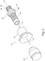
- Figs. 1 and 2 show a nozzle apparatus 10 comprising a screen apparatus 20 (comprising an entry segregator 22 and a main screen 23), an outer body 30 and a debris pot 40.
- nozzle apparatus 10 may be attached to a T-piece 16 of a water pipe 14 or any fluid delivery system exit.
- the water pipe 14 contains water polluted by particulate debris 18.
- polluted water flows through a central passage 12 of the nozzle apparatus 10 and the water continues through the main screen 23 and through an outlet or exit channel 36 which directs it to the surrounding area.
- the particulate debris 18 which is too large to flow through the main screen 23, is directed to the container referred to as a debris pot 40.
- the debris remains out of the way of the main screen 23 which prevents blockage of the screen 23 or blockage of the exit channel 36, thus allowing the nozzle apparatus 10 to function properly.
- the debris pot 40 may be removed and replaced periodically to remove accumulated debris, which can be weighed to calculate corrosion rate as described below.
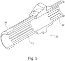
- the screen apparatus 20 shown in more detail in Figs. 4 and 5 , comprises an entry segregator 22 which comprises a series of linear slots 25, which allow water and smaller particles to travel therethrough, but which block the passage of larger particles.
- the main screen 23 comprises a similar series of slots 27 (although typically somewhat longer) which separates the polluted water into (i) a debris enriched stream and (ii)a purer water stream .
- the entry segregator 22 and main screen 23 are mounted in axial alignment on either side of a hexagonal nut 24.
- the passage 12 extends through the entry segregator 22, nut 24 and main screen 23. A portion of the nut 24 extends radially outward from the entry segregator 22 and main screen 23, to provide a mounting for threads 28, 29 above and below, as described herein below.
- the entry segregator 22 provides additional capacity to the filtration capacity of the nozzle apparatus 10, since debris may accumulate between the edge of the T-piece 16 and the the entry segregator 22.
- the axial passage 12 (which is a larger aperture than the linear slots 20) is provided in the entry segregator 22 through which water as well as particles of various sizes can flow. Notably however, the passage 12 is large enough to receive the larger particles which cannot travel through the slots 25 in the entry segregator 22.
- the debris 18 builds up in this position, it will not block water flow and so not block the overall nozzle apparatus 10.
- the entry segregator 22 is particularly suitable for vertical positioned nozzles.
- the purer water stream travels through the slots 27 in the main screen 23 and out of the exit channel 36 and is directed by the outer body 30 to the surrounding area.
- FIG. 6 A larger view of the outer body 30 is shown in Fig. 6 . It comprises an angled portion 32 the inner part 31 of which, along with a matching portion on a tube 48, is shaped to direct the water flow to the desired area.
- the angled portion 32 extends radially outwards compared to the opposite tube 48 but this does not further assist in directing the flow of water. Rather, it provides a larger gripping surface and has a hex profile to allow the tightening it to the main screen 23 for ease of assembly.
- the body 30 also includes a cover portion 33 which defines a flowpath between its inner bore and the main screen 23.
- the outer body 30 may be replaced by a variety of different bodies of varying sizes and different angles 31 in order to be properly sized for its intended purpose. In this embodiment, the outer body 30 provides a hollow cone spray at a 45 degree angle.
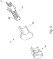
- the debris pot 40 is shown in more detail in Figs. 7 and 8 and comprises a container 42 with an end plate 44. At the open end of the debris pot, a socket 46 is threaded to receive a thread 26 on the end of the main screen 23 and a larger diameter (than the socket) tube portion 48 extends from the container 42 further in the axial direction.
- the screen apparatus 20 is affixed to the T-piece 16 via a thread 28 mounted on the nut flange 24.
- the entry segregator 22 thus extends up into the T-piece 16 or other pipework to which it is fitted and the main screen 23 extends from the opposite side of the nut 24 (normally in a downwards direction).
- the cover portion of the outer body 30 is then placed over the and around the main screen 23 and is affixed to the thread 29.
- the socket 46 in the the debris pot 40 is attached to a thread 26 at the end of the main screen 23.
- the edge 49 of the tube portion 48 is then aligned with and spaced slightly away from the inner end 31 of the outer body 30 and the resulting gap 18 (shown in Fig. 1 ) between them provides the exit channel 36 for the water.
- the edge 49 is angled to reflect the angle of the inlet end 31 of the outer body 30 (thus providing an angled channel), both of which may be varied depending on the desired coverage or other factors.
- the container 42 is sized to allow a large volume of debris to be trapped under pressure.
- embodiments of the present invention provide a debris free environment allowing water to pass through the nozzles ensuring it achieves the required K-Factor for its optimum performance.
- Embodiments of the present invention benefit in that to completely block the nozzle it will take very large amounts of scale and debris without maintenance from clearing out the debris pots unlike many existing solutions that will almost instantly fail.
- the nozzle can still deliver the volume and pressure of water required by the nozzle for its optimum performance if only two of these slots are free from debris.
- the exit channel 36 can be set at any angle.
- the angle on this example is 45 degrees, this is specific for cooling operations as it sends water forward at its optimal angle to reach its furthest point away from the structure it is protecting.
- This angle is matched by tube 48 of the debris pot 40 to form the exit channel 36.
- the debris pot 40 is no larger than the outer body 32.
- the main screen 23 and the cover 33 are sized to optimise the correct water volume and pressure through to the exit channel 36.
- the nozzle apparatus of figure 1 is shown attached to a T-piece but the nozzle apparatus can easily attach to any fluid transfer exit - an exit point vertical facing up or down - horizontal etc. could also be used that is within the scope of the appended claims.
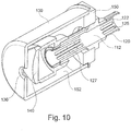
- Fig. 9 shows a second nozzle apparatus 110 ; like parts share the same reference numeral except preceded by a '1'.
- the nozzle apparatus 110 comprises a screen apparatus 120, an outer body 130 and a debris pot 140.
- the screen apparatus 120 and debris pot 140 function as described for the earlier embodiment, and will not be described further.
- the outer body 130 is a cylindrical shape with one end open and the opposite end having an exit channel 136.
- the outer body 130 encloses the debris trap 140, and is secured against a support member 150, which in turn is secured to a circumferentially extending nut 124 on the screen apparatus 120.
- the assembled nozzle apparatus 110 is shown in Fig. 10 .
- the water enters the nozzle apparatus through an entry segregator 122, which impedes the flow of debris particles through its smaller slots 125.
- the flow continues through the central passage 112 of the screen apparatus 120, through the slots 127 in the main screen 123 and then into a void 152 between the outer body 130 and debris pot 140/main screen 123. Particulate debris too large to proceed through the slots 127 reside in the debris pot 140.
- the water flow continues out of the exit channel 136, which can be suitably sized for the desired application, for example creating a mist. This arrangement allows a full cone spray profile.
- An advantage of certain embodiments of the invention is that the screens are provided in the nozzle apparatus close to the exit channel. Therefore, pollutants (such as scale coming off pipework) are caught from the pipework. This contrasts to other designs where a screen or filter is provided upstream in the pipework and any scale released downstream of the screen is not screened out and so may block the nozzles.
- FIG. 11 Some alternative screen apparatus 220, 320 is shown in Figs 11 and 12 and these function in a similar manner as the earlier embodiments.
- Fig. 12 it can be seen that the slots 325, 327 are arranged in a perpendicular direction to the flow of fluid in contrast to the earlier embodiments.
- the arrangement of the slots for preferred embodiments of the invention is configured such that the length of the outer body and the passage through the screen allow enough volume through to the outlet even if 80% of the screen is blocked.
- the provision of slots rather than small circular hole screens facilitates such an effect, which also minimises pressure build up on the screen and lost pressure from the expelled fluid.
- embodiments of the present invention allow storage of debris but it can also be used to determine the rate of corrosion within the deluge line. After every function test of the system all the debris pots can be removed with the debris being stored for weighing. The weight and volume of the debris can be calculated to show corrosion rate when referenced with the frequency of the test. This feature will allow the operator to evaluate the life of the whole system and determine when it requires a full re-structure and re-placement.
- FIG. 13a A further nozzle apparatus is shown in Figs. 13a - 13c and similar parts use the corresponding reference numerals of earlier embodiments except preceded by a '4'.
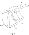
- the nozzle apparatus of Fig. 13a comprises an entry segregator 422, a main body 430 and a debris pot 440 which functions as described for earlier embodiments unless otherwise noted.
- an exit channel 436 is provided between the screen 423 and the housing 430, which is larger and directs fluid which has passed through the screen 423 towards the debris pot 440.
- the debris pot 440 has a plurality of slots 447 on the outside perimeter thereof.
- Each slot 447 extends vertically (as orientated in use) and towards the centre of the debris pot 430 typically by 5-25mm. Thus they are radially spaced from each other.
- relatively pure fluid is directed from the exit 436 onto the debris pot 430, which distributes the fluid into a pattern required in certain situations.
- the fluid will follow the path of the debris pot's 440 outer face design where it may flow through it and hit sections of it directing the flow in various directions. This will determine if the pattern is hollow cone or full cone pattern.
- the high velocity is normally full cone unless the housing 430 goes around the whole debris pot area (as per the Fig 10 embodiment).
- the distances 'c' and 'd' can be varied depending on the application requirements.
- d can be less than that shown in the figures and is typically 1 - 20 mm.
- the velocity may be reduced by extending the length 'd' between the exit 436 and the debris pot 440.
- the slots in the screen 423 may be less: 12 slots of 1mm width over the same area rather than 24 slots of 1mm for example. This would reduce the volume.
- FIG. 14a A further nozzle apparatus is shown in Figs. 14a ⁇ 14c and similar parts use the corresponding reference numerals of earlier embodiments except preceded by a '5'.
- the nozzle apparatus of Fig. 14a comprises an entry segregator 522, a main body 530 and a debris pot 540 which functions as described for earlier embodiments unless otherwise noted.
- the nozzle apparatus is orientated in an upwards direction during use and the pressure maintains the debris in the debris pot 540.
- the debris pot 540 has an angled flange 545 which is about 80 degrees to the housing 540.
- fluid proceeds through the entry segregator 522, through the main screen 523 and from between the housing 530 and the main screen 523 it is then directed by the angled portion 545 of the debris pot 540 to outside of the apparatus via an exit 536.
- nozzle apparatus shown in Figs. 13a-c and 14a-c are often more suited to medium to high velocity applications, or medium to low velocity applications, compared to the nozzle apparatus of earlier embodiments which are more suited to high velocity applications. Nonetheless any embodiment herewith can be used for any velocity application.
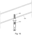
- Fig. 15 shows a nozzle apparatus 610 having an extended inlet 631 within the scope of the claims
- the inlet of this embodiment extends into a pipeline 614, as shown in
- the inlet extends in to the centre of the pipeline. In this way, even with debris built up on the inside of the pipeline 614, which would tend to block other nozzles, will not block so long as fluid is flowing through the centre of the pipeline 614.
- Such a configuration can be used with any of the nozzles disclosed herein.
- the end of the inlet 631 is within 5mm of the central axis of the pipeline 614 which has a diameter of 2,54 cm (1 inch) to 20,32 cm (8 inches).
- the inlet 631 also has a secondary portion 622, which allows fluid to flow therein, and also comprises a series of liner slots 625 to filter the fluid.
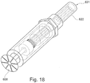
- Fig. 18 shows the Fig. 15 nozzle apparatus with the outer housing removed, showing some internal components, which generally function as described for earlier embodiments.
- the inlet 631 is provided as a separate piece, and during assembly is placed into the pipeline. The remaining parts of the nozzle apparatus are then connected to the separate inlet piece 631.
- the present embodiment also includes a dispersion plate 658 connected to the container by a cylindrical member.
- Embodiments of the invention have a multi-purpose use being able to achieve K-Factor for sprinkler.
- Embodiments of the invention are also safer in that less debris is distributed outwith the fluid. Such debris can cause injury to personnel e. g. it has been known to cut faces and has the potential to cause serious eye injuries.
Landscapes
- Health & Medical Sciences (AREA)
- Public Health (AREA)
- Business, Economics & Management (AREA)
- Emergency Management (AREA)
- Physics & Mathematics (AREA)
- Life Sciences & Earth Sciences (AREA)
- Chemical & Material Sciences (AREA)
- Analytical Chemistry (AREA)
- Biochemistry (AREA)
- General Health & Medical Sciences (AREA)
- General Physics & Mathematics (AREA)
- Immunology (AREA)
- Pathology (AREA)
- Nozzles (AREA)
- Fire-Extinguishing By Fire Departments, And Fire-Extinguishing Equipment And Control Thereof (AREA)
- Details Or Accessories Of Spraying Plant Or Apparatus (AREA)
- Filtration Of Liquid (AREA)
- Jet Pumps And Other Pumps (AREA)
Applications Claiming Priority (4)
| Application Number | Priority Date | Filing Date | Title |
|---|---|---|---|
| GB201212199A GB201212199D0 (en) | 2012-07-09 | 2012-07-09 | Nozzle apparatus |
| GB201218133A GB201218133D0 (en) | 2012-07-09 | 2012-10-10 | Improved nozzle apparatus |
| GB201308561A GB201308561D0 (en) | 2012-07-09 | 2013-05-13 | Nozzle apparatus and nozzle system |
| PCT/GB2013/051812 WO2014009714A1 (en) | 2012-07-09 | 2013-07-09 | Nozzle system |
Publications (2)
| Publication Number | Publication Date |
|---|---|
| EP2869936A1 EP2869936A1 (en) | 2015-05-13 |
| EP2869936B1 true EP2869936B1 (en) | 2021-12-08 |
Family
ID=46766382
Family Applications (2)
| Application Number | Title | Priority Date | Filing Date |
|---|---|---|---|
| EP13750359.5A Active EP2869936B1 (en) | 2012-07-09 | 2013-07-09 | Sprinkler system |
| EP13750091.4A Active EP2869935B1 (en) | 2012-07-09 | 2013-07-09 | Nozzle apparatus |
Family Applications After (1)
| Application Number | Title | Priority Date | Filing Date |
|---|---|---|---|
| EP13750091.4A Active EP2869935B1 (en) | 2012-07-09 | 2013-07-09 | Nozzle apparatus |
Country Status (14)
| Country | Link |
|---|---|
| US (2) | US10690577B2 (enExample) |
| EP (2) | EP2869936B1 (enExample) |
| JP (2) | JP2015527191A (enExample) |
| CN (1) | CN104602822B (enExample) |
| AU (2) | AU2013288470B2 (enExample) |
| BR (2) | BR112015000415B1 (enExample) |
| CA (2) | CA2878724C (enExample) |
| DK (2) | DK2869935T3 (enExample) |
| EA (2) | EA036454B1 (enExample) |
| GB (3) | GB201212199D0 (enExample) |
| MX (2) | MX2015000374A (enExample) |
| MY (1) | MY194235A (enExample) |
| SG (2) | SG11201500121TA (enExample) |
| WO (2) | WO2014009714A1 (enExample) |
Families Citing this family (8)
| Publication number | Priority date | Publication date | Assignee | Title |
|---|---|---|---|---|
| GB201212199D0 (en) | 2012-07-09 | 2012-08-22 | Rigdeluge Global Ltd | Nozzle apparatus |
| JP6081934B2 (ja) * | 2014-01-24 | 2017-02-15 | 東京エレクトロン株式会社 | 処理液ノズル及び塗布処理装置 |
| GB201406174D0 (en) | 2014-04-04 | 2014-05-21 | Rigdeluge Global Ltd | Filter |
| DE102014004958A1 (de) | 2014-04-05 | 2015-10-08 | Martin Rebhan | Ansaug-Zwischenfilter und -Krümmer zur Löschwasser-Reinigung |
| DE102015214123B3 (de) * | 2015-07-27 | 2016-07-14 | Lechler Gmbh | Filter für Hochdruckdüse, Hochdruckdüse und Verfahren zum Herstellen eines Filters für eine Hochdruckdüse |
| GB201517760D0 (en) * | 2015-10-07 | 2015-11-18 | Rigdeluge Global Ltd | Nozzle apparatus |
| GB2549965B (en) * | 2016-05-04 | 2019-07-17 | Rigdeluge Global Ltd | Hybrid nozzle |
| US20230023318A1 (en) * | 2021-07-22 | 2023-01-26 | Dan Swanson | Low pressure washer nozzle tip |
Family Cites Families (60)
| Publication number | Priority date | Publication date | Assignee | Title |
|---|---|---|---|---|
| CA492585A (en) | 1953-05-05 | E. Bartling Loren | Nozzle support for spray boom | |
| US1617858A (en) | 1923-03-30 | 1927-02-15 | George E March | Screen for nozzles |
| US1508480A (en) * | 1923-04-27 | 1924-09-16 | Charles W Skinner | Trap filter for irrigation |
| US1563490A (en) | 1924-10-03 | 1925-12-01 | Horton Spencer | Sprinkler installation |
| US2493982A (en) | 1948-03-26 | 1950-01-10 | Akron Brass Mfg Company Inc | Spray head for fire sprinkler systems |
| US2629632A (en) | 1948-10-28 | 1953-02-24 | H Munson Ralph | Spray nozzle |
| US3268176A (en) * | 1964-08-07 | 1966-08-23 | Spraying Systems Co | Spray nozzle having stabilizing tube and vane unit |
| US3273805A (en) | 1964-10-02 | 1966-09-20 | Ingersoll Rand Co | Pressurized fluid nozzle assembly |
| US3672578A (en) | 1970-08-20 | 1972-06-27 | Delavan Manufacturing Co | Nozzle |
| FR2229211A5 (en) | 1973-05-07 | 1974-12-06 | Desmarquest & Cec | Anti drip spray nozzle for agricultural use - flexible sleeve normally closed over supply holes is opened by press. |
| US4064046A (en) | 1976-06-02 | 1977-12-20 | Lloyd Dwight Gilger | Self-cleaning filter apparatus |
| US4331293A (en) | 1979-11-23 | 1982-05-25 | Rangel Garza Javier | Emitters for drip irrigation systems, micro-sprinklers and similars, of the pressure compensating type and also those types whose flow varies in relation to the changes in pressure |
| GB2142105B (en) | 1983-06-25 | 1986-06-04 | Spraytec Engineering Limited | Water supply means |
| JPS6164732A (ja) | 1984-09-06 | 1986-04-03 | Osaka Soda Co Ltd | ゴム接着方法 |
| JPS62174652A (ja) | 1986-01-28 | 1987-07-31 | Mitsubishi Metal Corp | アコ−ステイツク・エミツシヨンによるデクレピテ−シヨン測定装置 |
| JPH0344268Y2 (enExample) * | 1986-04-28 | 1991-09-18 | ||
| AU610098B2 (en) * | 1986-12-11 | 1991-05-16 | Spraying Systems Co. | Convertible spray nozzle |
| DE3741677A1 (de) | 1987-10-24 | 1989-05-03 | Kyoritsu Gokin Mfg | Entzunderungsstrahlrohr |
| JPH0673697B2 (ja) * | 1987-10-24 | 1994-09-21 | 株式会社共立合金製作所 | スケール除去用ノズル |
| JPH01125072A (ja) | 1987-11-09 | 1989-05-17 | Matsushita Electric Ind Co Ltd | 固体撮像装置 |
| JPH0367799U (enExample) * | 1989-10-27 | 1991-07-02 | ||
| US5269913A (en) * | 1991-10-02 | 1993-12-14 | Zarina Holding C.V. | Debris trap |
| JPH0852386A (ja) * | 1994-08-10 | 1996-02-27 | Kyoritsu Gokin Seisakusho:Kk | 流体噴射ノズル装置 |
| US5762269A (en) | 1996-05-14 | 1998-06-09 | Nelson Irrigation Corporation | Nozzle clip |
| US5839667A (en) | 1997-03-12 | 1998-11-24 | Grinnell Corporation | Pendent-type diffuser impingement water mist nozzle |
| US5863443A (en) * | 1997-06-16 | 1999-01-26 | Mainwaring; Timothy | In-line agricultural water filter with diverter tube and flush valve |
| SE510679C2 (sv) | 1997-08-29 | 1999-06-14 | Trelleborg Viking Asa | Rör eller slang som kan utstå hög värmeflödestäthet samt användning av röret eller slangen |
| JP2001113110A (ja) * | 1999-10-20 | 2001-04-24 | Yamato Valve:Kk | ストレーナ |
| IT1318617B1 (it) * | 2000-07-10 | 2003-08-27 | Novara Technology Srl | Processo sol-gel per la produzione di geli secchi di grandidimensioni e vetri derivati. |
| US6575307B2 (en) | 2000-10-10 | 2003-06-10 | Rain Bird Corporation | Self-cleaning water filter |
| US6450266B1 (en) | 2001-01-24 | 2002-09-17 | The Reliable Automatic Sprinkler Co., Inc. | Sprinkler arrangement for document storage |
| DE20103812U1 (de) | 2001-03-06 | 2001-08-09 | Systemtechnik Herzog GmbH, 39387 Oschersleben | Dralldüse zur Erzeugung von Sprühnebel |
| JP2003159549A (ja) | 2001-09-12 | 2003-06-03 | Ikeuchi:Kk | スプレーノズル |
| WO2004058427A1 (en) | 2002-12-25 | 2004-07-15 | Kyoritsu Gokin Co., Ltd. | Descaling nozzle |
| DE20301377U1 (de) | 2003-01-30 | 2003-05-28 | Herzog, Hans-Joachim, 39387 Oschersleben | Anschlussstück mit integrierten Sprühköpfen |
| CN2613319Y (zh) | 2003-03-31 | 2004-04-28 | 首安工业消防股份有限公司 | 细水雾喷头 |
| US7299999B2 (en) | 2003-04-02 | 2007-11-27 | Rain Bird Corporation | Rotating stream sprinkler with torque balanced reaction drive |
| US6951286B2 (en) | 2003-06-20 | 2005-10-04 | Mueller John R | Showerhead and filter assembly |
| US7000782B2 (en) * | 2003-12-05 | 2006-02-21 | Dosmatic Usa, Inc. | Backwash flushing filter |
| GB2441058B (en) | 2004-03-05 | 2008-08-27 | Optima Solutions Uk Ltd | Nozzle with fluid deflector arrangement |
| GB0405088D0 (en) | 2004-03-05 | 2004-04-07 | Optima Solutions Uk Ltd | Improved nozzle |
| GB2433710B (en) | 2004-03-05 | 2007-11-14 | Optima Solutions Uk Ltd | Nozzle having a fluid deflector |
| US7219684B2 (en) * | 2005-01-28 | 2007-05-22 | Rain Bird Corporation | Saddle tee and tool for irrigation lines |
| US8919678B2 (en) * | 2006-04-18 | 2014-12-30 | American Agriculture Products, Llc | Filtration and cleaning system for sprinkler irrigation drop nozzles |
| US7900854B2 (en) * | 2006-04-18 | 2011-03-08 | American Agriculture Products, Llc | Filtration and cleaning system for sprinkler irrigation drop nozzles |
| DE102007024247B3 (de) | 2007-05-15 | 2008-11-06 | Lechler Gmbh | Hochdruckdüse und Verfahren zum Herstellen einer Hochdruckdüse |
| DE102007024245B3 (de) | 2007-05-15 | 2008-08-28 | Lechler Gmbh | Sprühdüse |
| GB0804432D0 (en) | 2008-03-11 | 2008-04-16 | Rigcool Ltd | Boom |
| US7913937B2 (en) * | 2008-05-02 | 2011-03-29 | Spraying Systems Co. | Descaling spray nozzle assembly |
| JP2010221257A (ja) * | 2009-03-24 | 2010-10-07 | Kyoritsu Gokin Co Ltd | スプレーノズルとそのフィルター構造 |
| CN201524483U (zh) | 2009-09-15 | 2010-07-14 | 郭爱华 | 抽油井井口过滤装置 |
| JP5663276B2 (ja) * | 2010-11-18 | 2015-02-04 | ホーチキ株式会社 | トンネル水噴霧設備及びストレーナ装置 |
| US20120125867A1 (en) | 2010-11-24 | 2012-05-24 | Delaware Capital Formation, Inc. | Flushable filter device |
| CN201949711U (zh) | 2011-02-17 | 2011-08-31 | 上海大屯能源股份有限公司 | 喷水装置杂物过滤器 |
| JP6102170B2 (ja) * | 2011-12-22 | 2017-03-29 | Jfeスチール株式会社 | スプレーノズル用ノズルフィルタ及びスプレーノズル |
| GB2501886B (en) | 2012-05-08 | 2015-12-02 | Techtronic Floor Care Tech Ltd | Steam cleaners |
| CN104684485A (zh) | 2012-05-11 | 2015-06-03 | 3M创新有限公司 | 带噪声振动控制的生物声学传感器 |
| GB201212199D0 (en) | 2012-07-09 | 2012-08-22 | Rigdeluge Global Ltd | Nozzle apparatus |
| CN202667021U (zh) | 2012-07-11 | 2013-01-16 | 陈延芬 | 微雾喷头的过滤装置 |
| GB201406174D0 (en) | 2014-04-04 | 2014-05-21 | Rigdeluge Global Ltd | Filter |
-
2012
- 2012-07-09 GB GB201212199A patent/GB201212199D0/en not_active Ceased
- 2012-10-10 GB GB201218133A patent/GB201218133D0/en not_active Ceased
-
2013
- 2013-05-13 GB GB201308561A patent/GB201308561D0/en not_active Ceased
- 2013-07-09 DK DK13750091.4T patent/DK2869935T3/da active
- 2013-07-09 US US14/413,287 patent/US10690577B2/en active Active
- 2013-07-09 CN CN201380046482.8A patent/CN104602822B/zh active Active
- 2013-07-09 MX MX2015000374A patent/MX2015000374A/es unknown
- 2013-07-09 SG SG11201500121TA patent/SG11201500121TA/en unknown
- 2013-07-09 MY MYPI2015700089A patent/MY194235A/en unknown
- 2013-07-09 US US14/413,278 patent/US9833804B2/en active Active
- 2013-07-09 EA EA201590182A patent/EA036454B1/ru not_active IP Right Cessation
- 2013-07-09 WO PCT/GB2013/051812 patent/WO2014009714A1/en not_active Ceased
- 2013-07-09 BR BR112015000415-6A patent/BR112015000415B1/pt active IP Right Grant
- 2013-07-09 DK DK13750359.5T patent/DK2869936T3/da active
- 2013-07-09 EA EA201590181A patent/EA201590181A1/ru unknown
- 2013-07-09 CA CA2878724A patent/CA2878724C/en active Active
- 2013-07-09 SG SG11201500120YA patent/SG11201500120YA/en unknown
- 2013-07-09 AU AU2013288470A patent/AU2013288470B2/en active Active
- 2013-07-09 WO PCT/GB2013/051811 patent/WO2014009713A1/en not_active Ceased
- 2013-07-09 AU AU2013288469A patent/AU2013288469B2/en active Active
- 2013-07-09 CA CA2878723A patent/CA2878723A1/en not_active Abandoned
- 2013-07-09 EP EP13750359.5A patent/EP2869936B1/en active Active
- 2013-07-09 JP JP2015521061A patent/JP2015527191A/ja active Pending
- 2013-07-09 EP EP13750091.4A patent/EP2869935B1/en active Active
- 2013-07-09 JP JP2015521062A patent/JP2015531670A/ja active Pending
- 2013-07-09 MX MX2015000372A patent/MX2015000372A/es unknown
- 2013-07-09 BR BR112015000414-8A patent/BR112015000414B1/pt active IP Right Grant
Non-Patent Citations (1)
| Title |
|---|
| None * |
Also Published As
Similar Documents
| Publication | Publication Date | Title |
|---|---|---|
| EP2869936B1 (en) | Sprinkler system | |
| EP2969049B1 (en) | Cpvc sprinkler assembly with support member | |
| EA036482B1 (ru) | Распылительное устройство | |
| EP2981338B1 (en) | Filter | |
| EP3359860B1 (en) | Pipeline apparatus comprising a reducing bush | |
| RU2297865C1 (ru) | Ороситель | |
| US6158522A (en) | Fire-extinguisher nozzle | |
| CN104619428B (zh) | 喷嘴装置 | |
| GB2507728A (en) | A trap for collecting debris | |
| WO2018022812A1 (en) | Filter adapter | |
| WO2017103628A1 (en) | A sprinkler sysytem | |
| GB2503885A (en) | Nozzle Apparatus for a deluge system on a flare boom |
Legal Events
| Date | Code | Title | Description |
|---|---|---|---|
| PUAI | Public reference made under article 153(3) epc to a published international application that has entered the european phase |
Free format text: ORIGINAL CODE: 0009012 |
|
| 17P | Request for examination filed |
Effective date: 20150203 |
|
| AK | Designated contracting states |
Kind code of ref document: A1 Designated state(s): AL AT BE BG CH CY CZ DE DK EE ES FI FR GB GR HR HU IE IS IT LI LT LU LV MC MK MT NL NO PL PT RO RS SE SI SK SM TR |
|
| AX | Request for extension of the european patent |
Extension state: BA ME |
|
| DAX | Request for extension of the european patent (deleted) | ||
| RAP1 | Party data changed (applicant data changed or rights of an application transferred) |
Owner name: RIGDELUGE GLOBAL LIMITED |
|
| STAA | Information on the status of an ep patent application or granted ep patent |
Free format text: STATUS: EXAMINATION IS IN PROGRESS |
|
| 17Q | First examination report despatched |
Effective date: 20181102 |
|
| REG | Reference to a national code |
Ref country code: DE Ref legal event code: R079 Ref document number: 602013080333 Country of ref document: DE Free format text: PREVIOUS MAIN CLASS: B05B0015000000 Ipc: B05B0015400000 |
|
| RIC1 | Information provided on ipc code assigned before grant |
Ipc: B05B 15/50 20180101ALI20191218BHEP Ipc: B05B 15/65 20180101ALI20191218BHEP Ipc: B05B 15/40 20180101AFI20191218BHEP Ipc: A62C 31/02 20060101ALI20191218BHEP |
|
| GRAP | Despatch of communication of intention to grant a patent |
Free format text: ORIGINAL CODE: EPIDOSNIGR1 |
|
| STAA | Information on the status of an ep patent application or granted ep patent |
Free format text: STATUS: GRANT OF PATENT IS INTENDED |
|
| INTG | Intention to grant announced |
Effective date: 20210709 |
|
| GRAS | Grant fee paid |
Free format text: ORIGINAL CODE: EPIDOSNIGR3 |
|
| GRAA | (expected) grant |
Free format text: ORIGINAL CODE: 0009210 |
|
| STAA | Information on the status of an ep patent application or granted ep patent |
Free format text: STATUS: THE PATENT HAS BEEN GRANTED |
|
| AK | Designated contracting states |
Kind code of ref document: B1 Designated state(s): AL AT BE BG CH CY CZ DE DK EE ES FI FR GB GR HR HU IE IS IT LI LT LU LV MC MK MT NL NO PL PT RO RS SE SI SK SM TR |
|
| REG | Reference to a national code |
Ref country code: GB Ref legal event code: FG4D |
|
| REG | Reference to a national code |
Ref country code: AT Ref legal event code: REF Ref document number: 1453348 Country of ref document: AT Kind code of ref document: T Effective date: 20211215 Ref country code: CH Ref legal event code: EP |
|
| REG | Reference to a national code |
Ref country code: DE Ref legal event code: R096 Ref document number: 602013080333 Country of ref document: DE |
|
| REG | Reference to a national code |
Ref country code: IE Ref legal event code: FG4D |
|
| REG | Reference to a national code |
Ref country code: DK Ref legal event code: T3 Effective date: 20220308 |
|
| REG | Reference to a national code |
Ref country code: NL Ref legal event code: FP |
|
| REG | Reference to a national code |
Ref country code: LT Ref legal event code: MG9D |
|
| PG25 | Lapsed in a contracting state [announced via postgrant information from national office to epo] |
Ref country code: RS Free format text: LAPSE BECAUSE OF FAILURE TO SUBMIT A TRANSLATION OF THE DESCRIPTION OR TO PAY THE FEE WITHIN THE PRESCRIBED TIME-LIMIT Effective date: 20211208 Ref country code: LT Free format text: LAPSE BECAUSE OF FAILURE TO SUBMIT A TRANSLATION OF THE DESCRIPTION OR TO PAY THE FEE WITHIN THE PRESCRIBED TIME-LIMIT Effective date: 20211208 Ref country code: FI Free format text: LAPSE BECAUSE OF FAILURE TO SUBMIT A TRANSLATION OF THE DESCRIPTION OR TO PAY THE FEE WITHIN THE PRESCRIBED TIME-LIMIT Effective date: 20211208 Ref country code: BG Free format text: LAPSE BECAUSE OF FAILURE TO SUBMIT A TRANSLATION OF THE DESCRIPTION OR TO PAY THE FEE WITHIN THE PRESCRIBED TIME-LIMIT Effective date: 20220308 |
|
| REG | Reference to a national code |
Ref country code: AT Ref legal event code: MK05 Ref document number: 1453348 Country of ref document: AT Kind code of ref document: T Effective date: 20211208 |
|
| REG | Reference to a national code |
Ref country code: NO Ref legal event code: T2 Effective date: 20211208 |
|
| PG25 | Lapsed in a contracting state [announced via postgrant information from national office to epo] |
Ref country code: SE Free format text: LAPSE BECAUSE OF FAILURE TO SUBMIT A TRANSLATION OF THE DESCRIPTION OR TO PAY THE FEE WITHIN THE PRESCRIBED TIME-LIMIT Effective date: 20211208 Ref country code: LV Free format text: LAPSE BECAUSE OF FAILURE TO SUBMIT A TRANSLATION OF THE DESCRIPTION OR TO PAY THE FEE WITHIN THE PRESCRIBED TIME-LIMIT Effective date: 20211208 Ref country code: HR Free format text: LAPSE BECAUSE OF FAILURE TO SUBMIT A TRANSLATION OF THE DESCRIPTION OR TO PAY THE FEE WITHIN THE PRESCRIBED TIME-LIMIT Effective date: 20211208 Ref country code: GR Free format text: LAPSE BECAUSE OF FAILURE TO SUBMIT A TRANSLATION OF THE DESCRIPTION OR TO PAY THE FEE WITHIN THE PRESCRIBED TIME-LIMIT Effective date: 20220309 Ref country code: ES Free format text: LAPSE BECAUSE OF FAILURE TO SUBMIT A TRANSLATION OF THE DESCRIPTION OR TO PAY THE FEE WITHIN THE PRESCRIBED TIME-LIMIT Effective date: 20211208 |
|
| PG25 | Lapsed in a contracting state [announced via postgrant information from national office to epo] |
Ref country code: SM Free format text: LAPSE BECAUSE OF FAILURE TO SUBMIT A TRANSLATION OF THE DESCRIPTION OR TO PAY THE FEE WITHIN THE PRESCRIBED TIME-LIMIT Effective date: 20211208 Ref country code: SK Free format text: LAPSE BECAUSE OF FAILURE TO SUBMIT A TRANSLATION OF THE DESCRIPTION OR TO PAY THE FEE WITHIN THE PRESCRIBED TIME-LIMIT Effective date: 20211208 Ref country code: RO Free format text: LAPSE BECAUSE OF FAILURE TO SUBMIT A TRANSLATION OF THE DESCRIPTION OR TO PAY THE FEE WITHIN THE PRESCRIBED TIME-LIMIT Effective date: 20211208 Ref country code: PT Free format text: LAPSE BECAUSE OF FAILURE TO SUBMIT A TRANSLATION OF THE DESCRIPTION OR TO PAY THE FEE WITHIN THE PRESCRIBED TIME-LIMIT Effective date: 20220408 Ref country code: EE Free format text: LAPSE BECAUSE OF FAILURE TO SUBMIT A TRANSLATION OF THE DESCRIPTION OR TO PAY THE FEE WITHIN THE PRESCRIBED TIME-LIMIT Effective date: 20211208 Ref country code: CZ Free format text: LAPSE BECAUSE OF FAILURE TO SUBMIT A TRANSLATION OF THE DESCRIPTION OR TO PAY THE FEE WITHIN THE PRESCRIBED TIME-LIMIT Effective date: 20211208 |
|
| PG25 | Lapsed in a contracting state [announced via postgrant information from national office to epo] |
Ref country code: PL Free format text: LAPSE BECAUSE OF FAILURE TO SUBMIT A TRANSLATION OF THE DESCRIPTION OR TO PAY THE FEE WITHIN THE PRESCRIBED TIME-LIMIT Effective date: 20211208 Ref country code: AT Free format text: LAPSE BECAUSE OF FAILURE TO SUBMIT A TRANSLATION OF THE DESCRIPTION OR TO PAY THE FEE WITHIN THE PRESCRIBED TIME-LIMIT Effective date: 20211208 |
|
| REG | Reference to a national code |
Ref country code: DE Ref legal event code: R097 Ref document number: 602013080333 Country of ref document: DE |
|
| PG25 | Lapsed in a contracting state [announced via postgrant information from national office to epo] |
Ref country code: IS Free format text: LAPSE BECAUSE OF FAILURE TO SUBMIT A TRANSLATION OF THE DESCRIPTION OR TO PAY THE FEE WITHIN THE PRESCRIBED TIME-LIMIT Effective date: 20220408 |
|
| PLBE | No opposition filed within time limit |
Free format text: ORIGINAL CODE: 0009261 |
|
| STAA | Information on the status of an ep patent application or granted ep patent |
Free format text: STATUS: NO OPPOSITION FILED WITHIN TIME LIMIT |
|
| PG25 | Lapsed in a contracting state [announced via postgrant information from national office to epo] |
Ref country code: AL Free format text: LAPSE BECAUSE OF FAILURE TO SUBMIT A TRANSLATION OF THE DESCRIPTION OR TO PAY THE FEE WITHIN THE PRESCRIBED TIME-LIMIT Effective date: 20211208 |
|
| 26N | No opposition filed |
Effective date: 20220909 |
|
| PG25 | Lapsed in a contracting state [announced via postgrant information from national office to epo] |
Ref country code: SI Free format text: LAPSE BECAUSE OF FAILURE TO SUBMIT A TRANSLATION OF THE DESCRIPTION OR TO PAY THE FEE WITHIN THE PRESCRIBED TIME-LIMIT Effective date: 20211208 |
|
| PG25 | Lapsed in a contracting state [announced via postgrant information from national office to epo] |
Ref country code: MC Free format text: LAPSE BECAUSE OF FAILURE TO SUBMIT A TRANSLATION OF THE DESCRIPTION OR TO PAY THE FEE WITHIN THE PRESCRIBED TIME-LIMIT Effective date: 20211208 |
|
| REG | Reference to a national code |
Ref country code: CH Ref legal event code: PL |
|
| REG | Reference to a national code |
Ref country code: BE Ref legal event code: MM Effective date: 20220731 |
|
| PG25 | Lapsed in a contracting state [announced via postgrant information from national office to epo] |
Ref country code: LU Free format text: LAPSE BECAUSE OF NON-PAYMENT OF DUE FEES Effective date: 20220709 Ref country code: LI Free format text: LAPSE BECAUSE OF NON-PAYMENT OF DUE FEES Effective date: 20220731 Ref country code: CH Free format text: LAPSE BECAUSE OF NON-PAYMENT OF DUE FEES Effective date: 20220731 |
|
| PG25 | Lapsed in a contracting state [announced via postgrant information from national office to epo] |
Ref country code: IT Free format text: LAPSE BECAUSE OF FAILURE TO SUBMIT A TRANSLATION OF THE DESCRIPTION OR TO PAY THE FEE WITHIN THE PRESCRIBED TIME-LIMIT Effective date: 20211208 Ref country code: BE Free format text: LAPSE BECAUSE OF NON-PAYMENT OF DUE FEES Effective date: 20220731 |
|
| P01 | Opt-out of the competence of the unified patent court (upc) registered |
Effective date: 20230518 |
|
| PG25 | Lapsed in a contracting state [announced via postgrant information from national office to epo] |
Ref country code: IE Free format text: LAPSE BECAUSE OF NON-PAYMENT OF DUE FEES Effective date: 20220709 |
|
| PG25 | Lapsed in a contracting state [announced via postgrant information from national office to epo] |
Ref country code: HU Free format text: LAPSE BECAUSE OF FAILURE TO SUBMIT A TRANSLATION OF THE DESCRIPTION OR TO PAY THE FEE WITHIN THE PRESCRIBED TIME-LIMIT; INVALID AB INITIO Effective date: 20130709 |
|
| PG25 | Lapsed in a contracting state [announced via postgrant information from national office to epo] |
Ref country code: MK Free format text: LAPSE BECAUSE OF FAILURE TO SUBMIT A TRANSLATION OF THE DESCRIPTION OR TO PAY THE FEE WITHIN THE PRESCRIBED TIME-LIMIT Effective date: 20211208 Ref country code: CY Free format text: LAPSE BECAUSE OF FAILURE TO SUBMIT A TRANSLATION OF THE DESCRIPTION OR TO PAY THE FEE WITHIN THE PRESCRIBED TIME-LIMIT Effective date: 20211208 |
|
| PG25 | Lapsed in a contracting state [announced via postgrant information from national office to epo] |
Ref country code: TR Free format text: LAPSE BECAUSE OF FAILURE TO SUBMIT A TRANSLATION OF THE DESCRIPTION OR TO PAY THE FEE WITHIN THE PRESCRIBED TIME-LIMIT Effective date: 20211208 |
|
| PG25 | Lapsed in a contracting state [announced via postgrant information from national office to epo] |
Ref country code: MT Free format text: LAPSE BECAUSE OF FAILURE TO SUBMIT A TRANSLATION OF THE DESCRIPTION OR TO PAY THE FEE WITHIN THE PRESCRIBED TIME-LIMIT Effective date: 20211208 |
|
| PGFP | Annual fee paid to national office [announced via postgrant information from national office to epo] |
Ref country code: GB Payment date: 20250506 Year of fee payment: 13 |
|
| PGFP | Annual fee paid to national office [announced via postgrant information from national office to epo] |
Ref country code: NL Payment date: 20250721 Year of fee payment: 13 |
|
| PGFP | Annual fee paid to national office [announced via postgrant information from national office to epo] |
Ref country code: DK Payment date: 20250725 Year of fee payment: 13 Ref country code: DE Payment date: 20250722 Year of fee payment: 13 |
|
| PGFP | Annual fee paid to national office [announced via postgrant information from national office to epo] |
Ref country code: NO Payment date: 20250725 Year of fee payment: 13 |
|
| PGFP | Annual fee paid to national office [announced via postgrant information from national office to epo] |
Ref country code: FR Payment date: 20250725 Year of fee payment: 13 |