EP2869156B1 - Mobiler Roboter - Google Patents
Mobiler Roboter Download PDFInfo
- Publication number
- EP2869156B1 EP2869156B1 EP14190339.3A EP14190339A EP2869156B1 EP 2869156 B1 EP2869156 B1 EP 2869156B1 EP 14190339 A EP14190339 A EP 14190339A EP 2869156 B1 EP2869156 B1 EP 2869156B1
- Authority
- EP
- European Patent Office
- Prior art keywords
- pattern
- convex
- mobile robot
- lens
- area
- Prior art date
- Legal status (The legal status is an assumption and is not a legal conclusion. Google has not performed a legal analysis and makes no representation as to the accuracy of the status listed.)
- Active
Links
Images


Classifications
-
- B—PERFORMING OPERATIONS; TRANSPORTING
- B25—HAND TOOLS; PORTABLE POWER-DRIVEN TOOLS; MANIPULATORS
- B25J—MANIPULATORS; CHAMBERS PROVIDED WITH MANIPULATION DEVICES
- B25J9/00—Program-controlled manipulators
- B25J9/10—Program-controlled manipulators characterised by positioning means for manipulator elements
-
- B—PERFORMING OPERATIONS; TRANSPORTING
- B25—HAND TOOLS; PORTABLE POWER-DRIVEN TOOLS; MANIPULATORS
- B25J—MANIPULATORS; CHAMBERS PROVIDED WITH MANIPULATION DEVICES
- B25J9/00—Program-controlled manipulators
- B25J9/16—Program controls
- B25J9/1674—Program controls characterised by safety, monitoring, diagnostic
- B25J9/1676—Avoiding collision or forbidden zones
-
- B—PERFORMING OPERATIONS; TRANSPORTING
- B25—HAND TOOLS; PORTABLE POWER-DRIVEN TOOLS; MANIPULATORS
- B25J—MANIPULATORS; CHAMBERS PROVIDED WITH MANIPULATION DEVICES
- B25J13/00—Controls for manipulators
- B25J13/08—Controls for manipulators by means of sensing devices, e.g. viewing or touching devices
-
- B—PERFORMING OPERATIONS; TRANSPORTING
- B25—HAND TOOLS; PORTABLE POWER-DRIVEN TOOLS; MANIPULATORS
- B25J—MANIPULATORS; CHAMBERS PROVIDED WITH MANIPULATION DEVICES
- B25J9/00—Program-controlled manipulators
- B25J9/16—Program controls
- B25J9/1694—Program controls characterised by use of sensors other than normal servo-feedback from position, speed or acceleration sensors, perception control, multi-sensor controlled systems, sensor fusion
- B25J9/1697—Vision controlled systems
-
- G—PHYSICS
- G01—MEASURING; TESTING
- G01S—RADIO DIRECTION-FINDING; RADIO NAVIGATION; DETERMINING DISTANCE OR VELOCITY BY USE OF RADIO WAVES; LOCATING OR PRESENCE-DETECTING BY USE OF THE REFLECTION OR RERADIATION OF RADIO WAVES; ANALOGOUS ARRANGEMENTS USING OTHER WAVES
- G01S17/00—Systems using the reflection or reradiation of electromagnetic waves other than radio waves, e.g. lidar systems
- G01S17/02—Systems using the reflection of electromagnetic waves other than radio waves
- G01S17/06—Systems determining position data of a target
- G01S17/46—Indirect determination of position data
-
- G—PHYSICS
- G01—MEASURING; TESTING
- G01S—RADIO DIRECTION-FINDING; RADIO NAVIGATION; DETERMINING DISTANCE OR VELOCITY BY USE OF RADIO WAVES; LOCATING OR PRESENCE-DETECTING BY USE OF THE REFLECTION OR RERADIATION OF RADIO WAVES; ANALOGOUS ARRANGEMENTS USING OTHER WAVES
- G01S17/00—Systems using the reflection or reradiation of electromagnetic waves other than radio waves, e.g. lidar systems
- G01S17/88—Lidar systems specially adapted for specific applications
- G01S17/93—Lidar systems specially adapted for specific applications for anti-collision purposes
- G01S17/931—Lidar systems specially adapted for specific applications for anti-collision purposes of land vehicles
-
- G—PHYSICS
- G01—MEASURING; TESTING
- G01S—RADIO DIRECTION-FINDING; RADIO NAVIGATION; DETERMINING DISTANCE OR VELOCITY BY USE OF RADIO WAVES; LOCATING OR PRESENCE-DETECTING BY USE OF THE REFLECTION OR RERADIATION OF RADIO WAVES; ANALOGOUS ARRANGEMENTS USING OTHER WAVES
- G01S7/00—Details of systems according to groups G01S13/00, G01S15/00, G01S17/00
- G01S7/48—Details of systems according to groups G01S13/00, G01S15/00, G01S17/00 of systems according to group G01S17/00
- G01S7/481—Constructional features, e.g. arrangements of optical elements
- G01S7/4814—Constructional features, e.g. arrangements of optical elements of transmitters alone
-
- G—PHYSICS
- G05—CONTROLLING; REGULATING
- G05D—SYSTEMS FOR CONTROLLING OR REGULATING NON-ELECTRIC VARIABLES
- G05D1/00—Control of position, course, altitude or attitude of land, water, air or space vehicles, e.g. using automatic pilots
- G05D1/02—Control of position or course in two dimensions
- G05D1/021—Control of position or course in two dimensions specially adapted to land vehicles
- G05D1/0231—Control of position or course in two dimensions specially adapted to land vehicles using optical position detecting means
- G05D1/0238—Control of position or course in two dimensions specially adapted to land vehicles using optical position detecting means using obstacle or wall sensors
- G05D1/024—Control of position or course in two dimensions specially adapted to land vehicles using optical position detecting means using obstacle or wall sensors in combination with a laser
-
- G—PHYSICS
- G05—CONTROLLING; REGULATING
- G05D—SYSTEMS FOR CONTROLLING OR REGULATING NON-ELECTRIC VARIABLES
- G05D1/00—Control of position, course, altitude or attitude of land, water, air or space vehicles, e.g. using automatic pilots
- G05D1/20—Control system inputs
- G05D1/24—Arrangements for determining position or orientation
- G05D1/242—Means based on the reflection of waves generated by the vehicle
-
- H—ELECTRICITY
- H04—ELECTRIC COMMUNICATION TECHNIQUE
- H04N—PICTORIAL COMMUNICATION, e.g. TELEVISION
- H04N5/00—Details of television systems
- H04N5/74—Projection arrangements for image reproduction, e.g. using eidophor
-
- A—HUMAN NECESSITIES
- A47—FURNITURE; DOMESTIC ARTICLES OR APPLIANCES; COFFEE MILLS; SPICE MILLS; SUCTION CLEANERS IN GENERAL
- A47L—DOMESTIC WASHING OR CLEANING; SUCTION CLEANERS IN GENERAL
- A47L2201/00—Robotic cleaning machines, i.e. with automatic control of the travelling movement or the cleaning operation
- A47L2201/04—Automatic control of the travelling movement; Automatic obstacle detection
-
- Y—GENERAL TAGGING OF NEW TECHNOLOGICAL DEVELOPMENTS; GENERAL TAGGING OF CROSS-SECTIONAL TECHNOLOGIES SPANNING OVER SEVERAL SECTIONS OF THE IPC; TECHNICAL SUBJECTS COVERED BY FORMER USPC CROSS-REFERENCE ART COLLECTIONS [XRACs] AND DIGESTS
- Y10—TECHNICAL SUBJECTS COVERED BY FORMER USPC
- Y10S—TECHNICAL SUBJECTS COVERED BY FORMER USPC CROSS-REFERENCE ART COLLECTIONS [XRACs] AND DIGESTS
- Y10S901/00—Robots
- Y10S901/01—Mobile robot
Definitions
- the present invention relates to a mobile robot detecting an obstacle using an optical pattern.
- robots developed for industry are applied to factory automation.
- application fields of robots are expanding and not only medical robots and aerospace robots but also home robots used in general homes have been developed.
- the robot cleaner is a kind of home appliance which autonomously travels about a cleaning area and absorbs foreign substances to clean the area.
- the robot cleaner spontaneously travels using a rechargeable battery and includes obstacle sensors to avoid obstacles.
- the obstacle sensors an ultrasonic sensor, an infrared sensor, etc. may be used.
- EP2623010A2 discloses a robot cleaner which includes an image input unit disposed in the casing, the image input unit including a plurality of light emitting parts for emitting light toward an obstacle and an image sensor for acquiring a 3D image of the obstacle onto which light is emitted from the plurality of light emitting parts.
- An object of the present invention is to provide a mobile robot emitting uniform optical pattern.
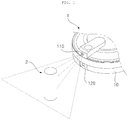
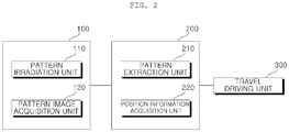
- a mobile robot in accordance with one embodiment of the present invention includes a mobile main body 10, an optical pattern sensor 100, and a controller 200.
- the optical pattern sensor 100 may include a pattern irradiation unit 110 emitting the optical pattern and a pattern image acquisition unit 120 photographing an area to which the optical pattern is emitted.
- the pattern irradiation unit 110 may include a light source and an optical pattern projection element (OPPE). Light incident from the light source is projected on the OPPE, thus generating the optical pattern.
- the light source may be a laser diode (LD) or a light emitting diode (LED). Laser light has greater monochromaticity, straightness, and connectivity than other light sources and may thus precisely measure distance. Particularly, infrared light or visible light causes a large deviation in precision of distance measurement due to factors such as colors and materials of target objects and thus the laser diode may be used as the light source.
- the OPPE may include a lens, a mask, or a diffractive optical element (DOE), and a lens used as the OPPE will be described later in more detail.
- DOE diffractive optical element
- the pattern irradiation unit 110 may emit light to an area in front of the main body 10.
- an emission direction of the optical pattern may be a slightly downward direction so that the optical pattern may be emitted to the floor in an active area of the mobile robot. That is, in order to form a viewing angle for recognition of a distance from an obstacle, the emission direction of the optical pattern (i.e., the direction of a main axis C of the lens 500, with reference to FIG. 6C ) and a main axis of a lens of the image acquisition unit 120 may not be parallel with each other and may form a designated angle.
- the main axis C of the lens 500 may be downward from a horizontal line so that the optical pattern may be emitted to the floor.
- the pattern image acquisition unit 120 acquires an input image by photographing the area to which the optical pattern is emitted.
- the pattern image acquisition unit 120 may include a camera, and such a camera may be a structured light camera.
- a cross-shaped pattern includes two pattern descriptors of a horizontal line and a vertical line intersecting the horizontal line. Since the horizontal line serves to recognize an obstacle condition of a wide range and the vertical line is set to only a degree required to move the mobile robot, the length of the horizontal line of the cross-shaped pattern may be greater than the length of the vertical line. Further, several combinations of horizontal lines and vertical lines may be provided and the optical pattern may be a pattern including one horizontal line and a plurality of vertical lines intersecting the horizontal line.
- the pattern extraction unit 210 detects a cross-shaped pattern descriptor formed by the vertical line and a line extending from the vertical line in the horizontal direction, among lines formed by the candidate points of the input image.
- the cross-shaped pattern descriptor doesn't need to be the entirety of a cross-shaped pattern. Since a vertical line pattern and a horizontal line pattern are modified according to the shape of a target object to which the optical pattern is emitted, although the shape of the pattern in the input image may be irregular and the size of a portion of the pattern at which the vertical line and the horizontal line intersect may be varied according to the shape of the target object, a '+'-shaped pattern descriptor is present at all times.
- the pattern extraction unit 210 may detect a pattern descriptor, corresponding to the shape of a template desired to acquire, from the input image and define an overall pattern including the pattern descriptor.
- the template In case of a cross-shaped optical pattern, the template has a '+' shape.
- the position information acquisition unit 220 may acquire position information, such as the width and height of the obstacle or a distance from the obstacle, based on the pattern defined by the pattern extraction unit 210. Since the emission direction of the pattern irradiation unit 110 is fixed, when the optical pattern is emitted to an area in which there is no obstacle, the position of the pattern in the input image is regular at all times.
- the input image in this case is defined as a reference input image. Position information of the pattern in the reference input image may be calculated in advance based on triangulation.
- a travel driving unit 300 serves to move the main body 10.
- the controller 200 may control the travel driving unit 300 according to position information acquired by the position information acquisition unit 220 so as to perform various traveling modes, such as avoiding obstacles, overcoming obstacles, and stopping.
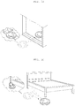
- FIGs. 3A to 3C are views illustrating movements of the mobile robot according to kinds of obstacles.
- FIG. 3A is a view illustrating movement of the mobile robot if an obstacle is a chair having legs of a designated height or more.
- the mobile robot may move while avoiding the legs of the chair according to position information of the legs acquired by the position information acquisition unit 220 (avoidance traveling) and pass through a space under the chair if the height of the legs is greater than the height of the mobile robot (passage traveling).
- FIG. 3B if the height of a threshold is low enough to overcome, the mobile robot may move while stepping over the threshold (conquest traveling).
- FIG. 3C is a view illustrating movement of the mobile robot if an obstacle is a bed.
- FIGs. 4 and 5 are views illustrating a robot cleaner, as one example of the mobile robot.
- the robot cleaner may further include a peripheral image acquisition unit 400 acquiring image information by photographing the surroundings around the robot cleaner, in addition to the optical pattern sensor 100 and the controller 200.
- the peripheral image acquisition unit 40 may include at least one camera installed so as to face the top or the front.
- FIG. 4 is a view illustrating a general example of the robot cleaner in which one camera faces the top.
- a position recognition unit 230 may extract feature points from an image acquired by the peripheral image acquisition unit 400 and recognize the position of the robot cleaner based on the feature points. Further, a map generation unit 420 may generate a peripheral map, i.e., a map of a cleaning space based on the position recognized by the position recognition unit 230. The map generation unit 420 may generate a peripheral map in which an obstruction state is reflected, in cooperation with the position information acquisition unit 220.
- the travel driving unit 300 may include a wheel motor driving at least one wheel installed under the main body 10 and move the main body 10 according to a driving signal.
- the robot cleaner may include left and right driving wheels. A pair of wheel motors may be provided to rotate the left and right driving wheels. These wheel motors are driven independent of each other and the robot cleaner may change direction by rotating directions of the left driving wheel and the right driving wheel and a difference of speeds between the left driving wheel and the right driving wheel. Further, the robot cleaner may further include a subsidiary wheel supporting the main body 10, in addition to the driving wheels. Thereby, friction between the lower surface of the main body 10 and the floor may be minimized and the robot cleaner may smoothly move.
- the robot cleaner may further include a storage unit 840.
- the storage unit 840 may store input images acquired by the pattern image acquisition unit 120, position information of an obstacle acquired by the position information acquisition unit 220, and a peripheral map generated by the map generation unit 240. Further, the storage unit 840 may store a control program driving the robot cleaner and data acquired therethrough.
- the storage unit 840 mainly uses a non-volatile memory (NVM or NVRAM).
- the non-volatile memory continuously maintains stored information even if power is not supplied.
- Non-volatile memories may include a ROM, a flash memory, a magnetic recording medium (for example, a hard disk, a floppy disk drive, or a magnetic tape), an optical disc drive, a magnetic RAM, a PRAM, etc.
- the robot cleaner may further include a cleaning unit 600 absorbing dust or foreign substances around the robot cleaner.
- the cleaning unit may include a dust case storing collected dust, a suction fan providing force to absorb dust from a cleaning area, and a suction motor rotating the suction fan to absorb dust.
- the cleaning unit 600 may include a rotary brush provided on the lower portion of the main body 10 and rotated about a horizontal axis to float dust on the floor or a carpet into air, and a plurality of blades may be provided on the outer surface of the rotary brush in a spiral direction.
- the robot cleaner may further include side brushes rotated about a vertical axis to clean a wall, a corner, etc., and the side brushes may be provided between the blades.
- the output unit 820 displays a cleaning method or a traveling method, such as reservation information, a battery state, concentrated cleaning, space extension, and zigzag-type driving.
- the output unit 820 may output operating states of the respective units forming the robot cleaner. Further, the output unit 820 may display obstacle information, position information, image information, an internal map, a cleaning, a cleaning map, a designated area, etc.
- the output unit 820 may include elements, such as a light emitting diode (LED), a liquid crystal display (LCD), a plasma display panel, an organic light emitting diode (OLED), etc.
- the power supply unit 830 may supply power to operate the respective units and include a rechargeable battery.
- the power supply unit 830 supplies not only power to drive the respective units but also operating power to perform traveling and cleaning and, if the remaining amount of power of the battery of the power supply unit 830 is insufficient, the robot cleaner moves to the charging station and the battery is recharged.
- the power supply unit 830 may further include a battery sensing unit to sense the recharge state of the battery.
- the controller 200 may display the remaining amount of power of the battery or the recharge state of the battery through the output unit 820 based on a sensing result of the battery sensing unit.
- FIGs. 6A to 6E illustrate the lens 500 of the pattern irradiation unit 110.
- FIG. 6A is a perspective view of the lens 500 of the pattern irradiation unit 110
- FIG. 6B is a front view of the lens 500 shown in FIG. 6A
- FIG. 6C is a bottom view of the lens 500 shown in FIG. 6A
- FIG. 6D is a right side view of the lens 500 shown in FIG. 6A
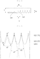
- FIG. 6E is a sectional view illustrating vertical convex cells 510 of FIG. 6A .
- the lens 500 generates a cross-shaped optical pattern by converting light emitted from the light source.
- Convex cells 510 and 520 having a convex profile and extended are formed on an incidence surface of the lens 500 upon which light is incident. Diffraction of light mainly occurs on the lens 500. That is, light incident upon the incidence surface of the lens 500 having the discontinuously formed convex cells 510 and 520 is converted into an optical pattern extended in the directions intersecting the lengthwise directions of the block cells 510 and 520.
- the lens 500 is a plano-convex cylindrical lens in which respective convex cells 510 and 520 are extended in the horizontal or vertical direction, an incidence surface is convex toward the light source, and an exit surface 530 is planar.
- the pattern irradiation unit 110 emits the optical pattern including a first pattern extended in a first direction and a second pattern extended in a second direction intersecting the first pattern part.
- Such an optical pattern is caused by structural characteristics of the lens 500.
- the lens 500 includes the convex cells 510 and 520 on the incidence surface upon which light emitted from the light source is incident, the incidence surface is divided into a first area I converting the light emitted from the light source into the first pattern and a second area II converting the light emitted from the light source into the second pattern, first convex cells 510 extended in parallel in a direction orthogonal to the first direction are formed in the first area I, and second convex cells 520 extended in parallel in a direction orthogonal to the second direction are formed in the second area II.
- a base part of a convex surface i.e., a point of the convex surface closest to the exit surface 530
- a valley r the highest peak of the convex surface, i.e., a point of the convex surface most distant from the exit surface 530
- a mountain h the highest peak of the convex surface, i.e., a point of the convex surface most distant from the exit surface 530
- a mountain h with reference to FIG. 6E
- a distance between adjacent valleys or a distance between adjacent mountains
- a distance between the valley and the mountain is defined as a height.
- a cross-shaped optical pattern may be generated by combination of a lens generating a horizontal line optical pattern and a separate lens generating a vertical line optical pattern
- a part of one lens may generate a horizontal line optical pattern and the other part may generate a vertical line optical pattern intersecting the horizontal line optical pattern.
- the lens 500 which will be described below corresponds to the latter.
- the lens 500 includes the incidence surface upon which light emitted from the light source is incident, and the incidence surface is divided into the first area I generating the horizontal line optical pattern and the second area II generating the vertical line optical pattern.
- a plurality of vertical convex cells 510 is formed in parallel in the first area I, and a plurality of horizontal convex cells 520 intersecting the vertical convex cells 510 is formed in parallel in the second area II.
- the center C of the lens 500 is aligned with the center of the light source and located in the first area I.
- a distance between the center C of the lens 500 and the boundary B between the first area I and the second area II is defined as an offset distance F. If the overall shape of the lens 500 is a circle, the incidence area of the first area I is greater than the incidence area of the second area II.
- the horizontal convex cells 520 may directly contact the vertical convex cell 510 closest to the second area II without an interval.
- the angle of view of the lens 500 with respect to the horizontal line may be a wide angle.
- the wide angle means that the angle of view is greater than the angle of view of a human being and it is known that the angle of view of a human being is generally about 50 degrees.
- the height Tv of the vertical convex cells 510 may be greater than the height Th of the horizontal convex cells 520.
- the angle of view of the lens 500 needs to be set in overall consideration of variables, such as the angle of incidence of light and the angle of reflection of light at the incidence surface, the diameter and thickness of the lens 500, the height and pitch of the convex cells 510 and 520, the offset distance of the lens 500, etc.
- variables such as the angle of incidence of light and the angle of reflection of light at the incidence surface, the diameter and thickness of the lens 500, the height and pitch of the convex cells 510 and 520, the offset distance of the lens 500, etc.
- definitions of these variables and an optimized design will be described.
- manufacture of a lens having a wide angle of view with respect to a horizontal line forming an optical pattern i.e., a wide horizontal angle of view
- a design in which the lens 500 has a wide horizontal angle of view i.e., 130 ⁇ 5 degrees
- the height Tv of the vertical convex cells 510 may be 1.0 to 1.2mm and the pitch Pv of the vertical convex cells 510 may be 0.8 to 1.0mm.
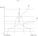
- the angle of view with respect to a horizontal line forming the optical pattern i.e., the horizontal angle of view, may be about 130 ⁇ 5 degrees.
- the height Th of the horizontal convex cells 520 may be 0.40 to 0.42mm and the pitch Ph of the horizontal convex cells 520 may be 0.8 to 1.0mm, i.e., is substantially the same as the pitch Pv of the vertical convex cells 510.
- the angle of view with respect to a vertical line forming the optical pattern i.e., a vertical angle of view, may be about 75 ⁇ 5 degrees.
- an angle a1 formed by a line connecting the common valley and the mountain of one vertical convex cell (hereinafter, referred to as a first vertical convex cell) and a line connecting the common valley and the mountain of the other vertical convex cell (hereinafter, referred to as a second vertical convex cell) may be within 43 degrees.
- a surface having a distance from the mountain h of the vertical convex cell 510 corresponding to 3/4 of the height Tv of the vertical convex cell 510 is defined as a 3/4 equipotential surface G(0.75)
- the angle a3 formed by a line connecting the common valley and a point on the 3/4 equipotential surface G(0.75) of the first vertical convex cell and a line connecting the common valley and a point on the 3/4 equipotential surface G(0.75) of the second vertical convex cell may be within 26 degrees.
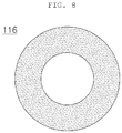
- FIG. 8 is a view illustrating an exit surface 116 of the light source of the pattern irradiation unit 110 in accordance with one embodiment of the present invention.
- the exit surface 116 of the light source through which light is emitted may be formed in a closed band type.
- the center of the light source does not emit light and thus, concentration of light on the center of the lens 500 may be prevented.
- the exit surface 116 is formed in a ring shape and the inner diameter and the outer diameter of the ring-shaped exit surface 116 are concentric. Although the inner diameter and the outer diameter of the exit surface 116 may be formed in a circle, the inner diameter and the outer diameter of the exit surface 116 may be formed in other closed curves, such as an oval.
- the pattern extraction unit 210 extracts a vertical line pattern from the input image.
- the vertical line pattern may be defined as a line having the greatest brightness difference with the peripheral surroundings from among lines extended in the vertical direction in the input image.
- the vertical line pattern is extracted from the above-described reference line.
- the pattern extraction unit 210 extracts a line connected to the extracted vertical line pattern in the horizontal direction from the vertical line pattern.
- the extracted patterns are compared with a designated cross-shaped template serving as a reference and thus, a cross-shaped pattern is recognized.
- the pattern extraction unit 210 extracts the vertical line pattern P2 from the input image. From among points recognized in the horizontal direction (in the direction X-X', with reference to FIGs. 9A and 9B ) in the input image, points brighter than the peripheral surroundings by a designated level or more are selected as candidate points and a line on which these candidate points are arranged in the vertical direction is defined as the vertical line pattern P2.
- the mobile robot in accordance with the present invention may emit a cross-shaped optical pattern in which light is uniformly distributed. Particularly, dispersion of light at the end of a horizontal line optical pattern may be prevented.
Landscapes
- Engineering & Computer Science (AREA)
- Physics & Mathematics (AREA)
- General Physics & Mathematics (AREA)
- Remote Sensing (AREA)
- Radar, Positioning & Navigation (AREA)
- Electromagnetism (AREA)
- Computer Networks & Wireless Communication (AREA)
- Mechanical Engineering (AREA)
- Robotics (AREA)
- Aviation & Aerospace Engineering (AREA)
- Automation & Control Theory (AREA)
- Optics & Photonics (AREA)
- Multimedia (AREA)
- Signal Processing (AREA)
- Human Computer Interaction (AREA)
- Control Of Position, Course, Altitude, Or Attitude Of Moving Bodies (AREA)
- Electric Vacuum Cleaner (AREA)
Claims (15)
- Mobiler Roboter, aufweisend:einen mobilen Hauptkörper (10); undeine Musterbestrahlungseinheit (110), die eingerichtet ist, ein optisches Muster einschließlich eines ersten Musters, das eine Linie aufweist, die sich in einer ersten Richtung erstreckt, und eines zweiten Musters, das eine Linie aufweist, die sich in einer zweiten Richtung erstreckt, die das erste Muster schneidet, in einen Bereich um den Hauptkörper (10) herum zu emittieren,wobei die Musterbestrahlungseinheit (110) aufweist:eine Lichtquelle, die eingerichtet ist, Licht zu emittieren; undeine Linse (500), die eingerichtet ist, um das von der Lichtquelle emittierte Licht in das optische Muster umzuwandeln,wobei die Linse (500) konvexe Zellen auf einer Einfallsfläche aufweist, auf die von der Lichtquelle emittiertes Licht einfallen soll, wobei die Einfallsfläche unterteilt ist in einen ersten Bereich (I), der eingerichtet ist, das von der Lichtquelle emittierte Licht in das erste Muster umzuwandeln, und einen zweiten Bereich (II), der eingerichtet ist, das von der Lichtquelle emittierte Licht in das zweite Muster umzuwandeln,wobei eine erste Vielzahl der ersten konvexen Zellen (510), wobei die erste Vielzahl sich in einer Richtung orthogonal zu der ersten Richtung erstreckt, parallel in dem ersten Bereich (I) gebildet ist, und wobei eine zweite Vielzahl der zweiten konvexen Zellen (520), wobei die zweite Vielzahl sich in einer Richtung orthogonal zu der zweiten Richtung erstreckt, parallel in dem zweiten Bereich (II) gebildet ist.
- Mobiler Roboter nach Anspruch 1, wobei
das optische Muster ein kreuzförmiges optisches Muster ist;
die erste Richtung die horizontale Richtung ist und das erste Muster, das eine Linie aufweist, die sich in der ersten Richtung erstreckt, ein horizontales optisches Linienmuster ist;
die zweite Richtung die vertikale Richtung ist und das zweite Muster, das eine Linie aufweist, die sich in der zweiten Richtung erstreckt, ein vertikales optisches Linienmuster ist;
die ersten konvexen Zellen (510) vertikale konvexe Zellen sind; und
die zweiten konvexen Zellen (520) horizontale konvexe Zellen sind. - Mobiler Roboter nach einem der vorhergehenden Ansprüche, wobei sich die Mitte der Linse (500) in dem ersten Bereich (I) befindet.
- Mobiler Roboter nach einem der vorhergehenden Ansprüche, wobei der Einfallsbereich des ersten Bereichs (I) größer ist als der Einfallsbereich des zweiten Bereichs (II).
- Mobiler Roboter nach einem der vorhergehenden Ansprüche, wobei der Bildwinkel der Linse (500) in Bezug auf das erste Muster größer ist als der Bildwinkel der Linse (500) in Bezug auf das zweite Muster.
- Mobiler Roboter nach einem der vorhergehenden Ansprüche, wobei die Höhe der ersten konvexen Zellen (510) größer ist als die Höhe der zweiten konvexen Zellen (520).
- Mobiler Roboter nach einem der vorhergehenden Ansprüche, wobei Spitzen der ersten konvexen Zellen (510) und Spitzen der zweiten konvexen Zellen (520) auf der gleichen Höhe von der Austrittsfläche (530) der Linse (500) eingerichtet sind,
und/oder
wobei das Verhältnis von Höhe zu Abstand der ersten konvexen Zellen (510) größer ist als das Verhältnis von Höhe zu Abstand der zweiten konvexen Zellen (520). - Mobiler Roboter nach einem der vorhergehenden Ansprüche, wobei der Winkel, der gebildet wird zwischen einer Linie, die das gemeinsame Tal benachbarter erster konvexer Zellen (510) mit der Spitze einer der benachbarten ersten konvexen Zellen verbindet, und einer Linie, die das gemeinsame Tal mit der Spitze der anderen benachbarten ersten konvexen Zellen verbindet, innerhalb von 43 Grad liegt.
- Mobiler Roboter nach einem der vorhergehenden Ansprüche, wobei der Winkel, der gebildet wird zwischen einer Linie, die das gemeinsame Tal benachbarter erster konvexer Zellen (510) mit dem Punkt verbindet, der 1/4 der Höhe von der Spitze einer der benachbarten ersten konvexen Zellen entspricht, und einer Linie, die das gemeinsame Tal mit dem Punkt verbindet, der 1/4 der Höhe von der Spitze der anderen benachbarten ersten konvexen Zellen entspricht, innerhalb von 30 Grad liegt, wobei die Höhe als der Abstand von dem Tal einer ersten konvexen Zelle zu der Spitze der ersten konvexen Zelle definiert ist,
und/oder
wobei der Winkel zwischen einer Linie, die ein gemeinsames Tal benachbarter erster konvexer Zellen (510) mit dem Punkt verbindet, der 3/4 der Höhe von der Spitze einer der benachbarten ersten konvexen Zellen entspricht, und einer Linie, die das gemeinsame Tal mit dem Punkt verbindet, der 3/4 der Höhe von der Spitze der anderen benachbarten ersten konvexen Zelle entspricht, innerhalb von 26 Grad ist, wobei die Höhe als der Abstand von dem Tal einer ersten konvexen Zelle zu der Spitze der ersten konvexen Zelle definiert ist. - Mobiler Roboter nach einem der vorhergehenden Ansprüche, wobei die zweiten konvexen Zellen (520) die erste konvexe Zelle kontaktieren, die dem zweiten Bereich (II) am nächsten liegt.
- Mobiler Roboter nach einem der vorhergehenden Ansprüche, wobei die Täler der ersten konvexen Zellen (510) tiefer sind als die Täler der zweiten konvexen Zellen (520) an der Grenze zwischen dem ersten Bereich (I) und dem zweiten Bereich (II).
- Mobiler Roboter nach einem der vorhergehenden Ansprüche, wobei die Lichtquelle eine Austrittsfläche aufweist, die in der Art eines geschlossenen Bandes gebildet ist,
und/oder
wobei die Lichtquelle eine Laserdiode aufweist,
und/oder
wobei die Hauptachse der Linse (500) von einer horizontalen Linie aus abwärts gerichtet ist. - Mobiler Roboter nach einem der vorhergehenden Ansprüche, ferner aufweisend eine Musterbilderfassungseinheit (120), die eingerichtet ist, ein Eingangsbild eines Bereichs zu erfassen, auf den das optische Muster emittiert wird,
optional,
wobei die Linse (500) der Musterbestrahlungseinheit (110) und eine Linse der Musterbilderfassungseinheit (120) auf einer vertikalen Linie ausgerichtet sind. - Mobiler Roboter nach Anspruch 13, ferner aufweisend eine Musterextraktionseinheit (210), die eingerichtet ist, ein bestimmtes Muster aus dem von der Musterbildaufnahmeeinheit (120) erfassten Eingangsbild zu extrahieren.
- Mobiler Roboter nach Anspruch 14, wobei, wenn, nachdem das kreuzförmige Muster aus dem Eingangsbild durch die Musterextraktionseinheit (210) extrahiert ist, kein kreuzförmiges Muster aus einem Eingangsbild extrahiert wird, das wieder erfasst wird an einer zufälligen Position durch die Musterbilderfassungseinheit (120), der mobile Roboter eingerichtet ist, eine Vermeidungsfahrt durchzuführen, bevor sich der mobile Roboter um einen vorbestimmten Abstand von der zufälligen Position bewegt;
und/oder
wenn ein proximales Ende des optischen Musters mit der vertikalen Linie, das den kürzesten Abstand von dem Hauptkörper (10) hat, nicht durch die Musterextraktionseinheit (210) aus dem Eingangsbild detektiert wird, der mobile Roboter eingerichtet ist, eine Vermeidungsfahrt durchzuführen, bevor der mobile Roboter sich um einen vorbestimmten Abstand bewegt.
Applications Claiming Priority (1)
| Application Number | Priority Date | Filing Date | Title |
|---|---|---|---|
| KR1020130131622A KR102152641B1 (ko) | 2013-10-31 | 2013-10-31 | 이동 로봇 |
Publications (2)
| Publication Number | Publication Date |
|---|---|
| EP2869156A1 EP2869156A1 (de) | 2015-05-06 |
| EP2869156B1 true EP2869156B1 (de) | 2017-08-23 |
Family
ID=51870822
Family Applications (1)
| Application Number | Title | Priority Date | Filing Date |
|---|---|---|---|
| EP14190339.3A Active EP2869156B1 (de) | 2013-10-31 | 2014-10-24 | Mobiler Roboter |
Country Status (4)
| Country | Link |
|---|---|
| US (1) | US9440355B2 (de) |
| EP (1) | EP2869156B1 (de) |
| KR (1) | KR102152641B1 (de) |
| CN (1) | CN104597902B (de) |
Cited By (1)
| Publication number | Priority date | Publication date | Assignee | Title |
|---|---|---|---|---|
| RU2800503C1 (ru) * | 2019-08-21 | 2023-07-21 | Дриме Инновэйшн Текнолоджи (Сучжоу) Ко., Лтд. | Робот-уборщик и способ автоматического управления роботом-уборщиком |
Families Citing this family (70)
| Publication number | Priority date | Publication date | Assignee | Title |
|---|---|---|---|---|
| US10219665B2 (en) | 2013-04-15 | 2019-03-05 | Aktiebolaget Electrolux | Robotic vacuum cleaner with protruding sidebrush |
| CN110448222A (zh) | 2013-04-15 | 2019-11-15 | 伊莱克斯公司 | 机器人真空吸尘器 |
| WO2015090399A1 (en) | 2013-12-19 | 2015-06-25 | Aktiebolaget Electrolux | Robotic cleaning device and method for landmark recognition |
| US10433697B2 (en) | 2013-12-19 | 2019-10-08 | Aktiebolaget Electrolux | Adaptive speed control of rotating side brush |
| KR102116595B1 (ko) | 2013-12-20 | 2020-06-05 | 에이비 엘렉트로룩스 | 먼지통 |
| US10518416B2 (en) | 2014-07-10 | 2019-12-31 | Aktiebolaget Electrolux | Method for detecting a measurement error in a robotic cleaning device |
| US10729297B2 (en) | 2014-09-08 | 2020-08-04 | Aktiebolaget Electrolux | Robotic vacuum cleaner |
| KR101620427B1 (ko) * | 2014-10-14 | 2016-05-12 | 엘지전자 주식회사 | 로봇 청소기의 제어방법 |
| WO2016091291A1 (en) | 2014-12-10 | 2016-06-16 | Aktiebolaget Electrolux | Using laser sensor for floor type detection |
| CN107072454A (zh) | 2014-12-12 | 2017-08-18 | 伊莱克斯公司 | 侧刷和机器人吸尘器 |
| JP6532530B2 (ja) * | 2014-12-16 | 2019-06-19 | アクチエボラゲット エレクトロルックス | ロボット掃除機の掃除方法 |
| CN107003669B (zh) | 2014-12-16 | 2023-01-31 | 伊莱克斯公司 | 用于机器人清洁设备的基于经验的路标 |
| KR102343513B1 (ko) | 2015-04-17 | 2021-12-28 | 에이비 엘렉트로룩스 | 로봇 청소 장치 및 로봇 청소 장치의 제어 방법 |
| DE102015109775B3 (de) | 2015-06-18 | 2016-09-22 | RobArt GmbH | Optischer Triangulationssensor zur Entfernungsmessung |
| US10402792B2 (en) | 2015-08-13 | 2019-09-03 | The Toronto-Dominion Bank | Systems and method for tracking enterprise events using hybrid public-private blockchain ledgers |
| US11069082B1 (en) * | 2015-08-23 | 2021-07-20 | AI Incorporated | Remote distance estimation system and method |
| WO2017036532A1 (en) | 2015-09-03 | 2017-03-09 | Aktiebolaget Electrolux | System of robotic cleaning devices |
| DE102015114883A1 (de) | 2015-09-04 | 2017-03-09 | RobArt GmbH | Identifizierung und Lokalisierung einer Basisstation eines autonomen mobilen Roboters |
| DE102015119501A1 (de) | 2015-11-11 | 2017-05-11 | RobArt GmbH | Unterteilung von Karten für die Roboternavigation |
| DE102015119865B4 (de) | 2015-11-17 | 2023-12-21 | RobArt GmbH | Robotergestützte Bearbeitung einer Oberfläche mittels eines Roboters |
| DE102015121666B3 (de) | 2015-12-11 | 2017-05-24 | RobArt GmbH | Fernsteuerung eines mobilen, autonomen Roboters |
| DE102016102644A1 (de) | 2016-02-15 | 2017-08-17 | RobArt GmbH | Verfahren zur Steuerung eines autonomen mobilen Roboters |
| JP6685755B2 (ja) * | 2016-02-16 | 2020-04-22 | 東芝ライフスタイル株式会社 | 自律走行体 |
| US11169533B2 (en) * | 2016-03-15 | 2021-11-09 | Aktiebolaget Electrolux | Robotic cleaning device and a method at the robotic cleaning device of performing cliff detection |
| US11122953B2 (en) | 2016-05-11 | 2021-09-21 | Aktiebolaget Electrolux | Robotic cleaning device |
| TWI653964B (zh) * | 2016-05-17 | 2019-03-21 | Lg Electronics Inc. | 行動機器人及其控制方法 |
| KR102147207B1 (ko) * | 2016-08-29 | 2020-08-24 | 엘지전자 주식회사 | 이동 로봇 및 그 제어방법 |
| KR102147208B1 (ko) * | 2016-09-01 | 2020-08-24 | 엘지전자 주식회사 | 이동 로봇 및 그 제어방법 |
| TWI639021B (zh) * | 2016-05-17 | 2018-10-21 | 南韓商Lg電子股份有限公司 | 行動機器人及其控制方法 |
| TWI689387B (zh) * | 2016-05-17 | 2020-04-01 | 南韓商Lg電子股份有限公司 | 行動機器人 |
| US10463212B2 (en) | 2016-05-20 | 2019-11-05 | Lg Electronics Inc. | Autonomous cleaner |
| AU2017266809B2 (en) * | 2016-05-20 | 2019-08-22 | Lg Electronics Inc. | Robot cleaner |
| WO2017200348A1 (ko) | 2016-05-20 | 2017-11-23 | 엘지전자 주식회사 | 로봇 청소기 |
| WO2017200345A1 (ko) | 2016-05-20 | 2017-11-23 | 엘지전자 주식회사 | 로봇 청소기 |
| WO2017200347A1 (ko) | 2016-05-20 | 2017-11-23 | 엘지전자 주식회사 | 로봇 청소기 |
| WO2017200350A1 (ko) | 2016-05-20 | 2017-11-23 | 엘지전자 주식회사 | 로봇 청소기 |
| US10441128B2 (en) | 2016-05-20 | 2019-10-15 | Lg Electronics Inc. | Autonomous cleaner |
| US10342405B2 (en) | 2016-05-20 | 2019-07-09 | Lg Electronics Inc. | Autonomous cleaner |
| WO2017200349A1 (ko) | 2016-05-20 | 2017-11-23 | 엘지전자 주식회사 | 로봇 청소기 |
| US10420448B2 (en) | 2016-05-20 | 2019-09-24 | Lg Electronics Inc. | Autonomous cleaner |
| EP3459692B1 (de) | 2016-05-20 | 2022-03-30 | LG Electronics Inc. | Roboterreiniger |
| US12140965B2 (en) | 2016-08-05 | 2024-11-12 | Rotrade Asset Management Gmbh | Method for controlling an autonomous mobile robot |
| AU2017316090B2 (en) * | 2016-08-25 | 2020-10-29 | Lg Electronics Inc. | Mobile robot and control method therefor |
| KR102428214B1 (ko) * | 2016-09-01 | 2022-08-01 | 엘지전자 주식회사 | 이동 로봇 및 그 제어방법 |
| TWI626427B (zh) * | 2016-12-28 | 2018-06-11 | 合盈光電科技股份有限公司 | 適用於機器人之監測系統 |
| KR20180082264A (ko) * | 2017-01-10 | 2018-07-18 | 엘지전자 주식회사 | 이동 로봇 및 그 제어방법 |
| EP3590014B1 (de) | 2017-03-02 | 2021-11-17 | Robart GmbH | Verfahren zur steuerung eines autonomen, mobilen roboters |
| DE102017105724A1 (de) * | 2017-03-16 | 2018-09-20 | Vorwerk & Co. Interholding Gmbh | Verfahren zum Betrieb eines sich selbsttätig fortbewegenden Bodenbearbeitungsgerätes |
| DE102017109219A1 (de) | 2017-04-28 | 2018-10-31 | RobArt GmbH | Verfahren für die Roboternavigation |
| JP7243967B2 (ja) * | 2017-06-02 | 2023-03-22 | アクチエボラゲット エレクトロルックス | ロボット清掃デバイスの前方の表面のレベル差を検出する方法 |
| CN111093447B (zh) | 2017-09-26 | 2022-09-02 | 伊莱克斯公司 | 机器人清洁设备的移动控制 |
| CN108107892B (zh) * | 2017-12-22 | 2020-12-25 | 重庆秉为科技有限公司 | 一种智能清扫仪器控制方法 |
| US11009882B2 (en) | 2018-01-12 | 2021-05-18 | Pixart Imaging Inc. | Method, system for obstacle detection and a sensor subsystem |
| US11507097B2 (en) * | 2018-02-05 | 2022-11-22 | Pixart Imaging Inc. | Control apparatus for auto clean machine and auto clean machine control method |
| KR102070283B1 (ko) * | 2018-05-16 | 2020-01-28 | 엘지전자 주식회사 | 청소기 및 그 제어방법 |
| GB2574417B (en) | 2018-06-05 | 2021-03-03 | Dyson Technology Ltd | A vision system for a mobile robot |
| JP7129659B2 (ja) * | 2018-09-18 | 2022-09-02 | パナソニックIpマネジメント株式会社 | 自走式掃除機 |
| US11353884B2 (en) * | 2019-01-28 | 2022-06-07 | Pixart Imaging Inc. | Robot without detection dead zone |
| KR102210360B1 (ko) * | 2019-03-05 | 2021-01-29 | 엘지전자 주식회사 | 이동 로봇 및 이동 로봇의 제어방법 |
| KR102672220B1 (ko) * | 2019-06-28 | 2024-06-07 | 엘지전자 주식회사 | 지능형 로봇 청소기 |
| CN110353583A (zh) * | 2019-08-21 | 2019-10-22 | 追创科技(苏州)有限公司 | 扫地机器人及扫地机器人的自动控制方法 |
| KR102320678B1 (ko) * | 2020-02-28 | 2021-11-02 | 엘지전자 주식회사 | 이동 로봇 및 그 제어방법 |
| CN111552289B (zh) * | 2020-04-28 | 2021-07-06 | 苏州高之仙自动化科技有限公司 | 检测方法及虚拟雷达装置、电子设备、存储介质 |
| CN111390917B (zh) * | 2020-05-08 | 2021-07-16 | 苏州博众机器人有限公司 | 一种机器人防碰撞装置、方法和机器人 |
| CN111562567B (zh) * | 2020-05-11 | 2021-04-30 | 北京驭光科技发展有限公司 | 移动装置的障碍物侦测系统、移动装置及扫地机器人 |
| CN113558523A (zh) * | 2021-06-22 | 2021-10-29 | 惠州越登智能科技有限公司 | 激光雷达障碍检测装置、设备及检测方法 |
| CN113721301B (zh) * | 2021-08-17 | 2024-12-13 | 广东盈峰智能环卫科技有限公司 | 一种悬崖检测方法及装置 |
| US20240189067A1 (en) * | 2022-12-08 | 2024-06-13 | Hedgehog LLC | Cleaning surgical instruments |
| DE102023201254A1 (de) * | 2023-02-14 | 2024-08-14 | BSH Hausgeräte GmbH | Steuerung eines Bodenroboters mit einer Seitenbürste |
| CN115979251B (zh) * | 2023-03-20 | 2023-06-27 | 深圳鹏行智能研究有限公司 | 地图的生成方法和机器人 |
Family Cites Families (13)
| Publication number | Priority date | Publication date | Assignee | Title |
|---|---|---|---|---|
| JP3288523B2 (ja) * | 1994-02-22 | 2002-06-04 | 株式会社ワコム | 光点位置計測装置及び光点位置計測方法 |
| US6229562B1 (en) * | 1997-07-08 | 2001-05-08 | Stanley H. Kremen | System and apparatus for the recording and projection of images in substantially 3-dimensional format |
| US6496754B2 (en) * | 2000-11-17 | 2002-12-17 | Samsung Kwangju Electronics Co., Ltd. | Mobile robot and course adjusting method thereof |
| JP4579575B2 (ja) * | 2004-05-14 | 2010-11-10 | 株式会社半導体エネルギー研究所 | レーザ照射方法及びレーザ照射装置 |
| US7182260B2 (en) * | 2004-06-29 | 2007-02-27 | Symbol Technologies, Inc. | Aiming light pattern generator in imaging readers for electro-optically reading indicia |
| KR100735565B1 (ko) * | 2006-05-17 | 2007-07-04 | 삼성전자주식회사 | 구조광을 이용한 물체 검출 방법 및 이를 이용한 로봇 |
| EP2128694B1 (de) * | 2007-03-19 | 2014-02-26 | Panasonic Corporation | Laserbeleuchtungseinrichtung und bildanzeigeeinrichtung |
| KR101850386B1 (ko) * | 2011-04-19 | 2018-04-19 | 엘지전자 주식회사 | 로봇 청소기 및 이의 제어 방법 |
| KR101798045B1 (ko) * | 2011-05-12 | 2017-11-15 | 엘지전자 주식회사 | 로봇 청소기 및 이의 제어 방법 |
| DE102011051729A1 (de) * | 2011-07-11 | 2013-01-17 | Alfred Kärcher Gmbh & Co. Kg | Selbstfahrendes Bodenreinigungsgerät |
| KR20130090438A (ko) * | 2012-02-04 | 2013-08-14 | 엘지전자 주식회사 | 로봇 청소기 |
| EP2631730B1 (de) * | 2012-02-24 | 2014-09-24 | Samsung Electronics Co., Ltd | Sensoranordnung und Roboterreiniger damit |
| KR101949277B1 (ko) * | 2012-06-18 | 2019-04-25 | 엘지전자 주식회사 | 이동 로봇 |
-
2013
- 2013-10-31 KR KR1020130131622A patent/KR102152641B1/ko not_active Expired - Fee Related
-
2014
- 2014-10-24 EP EP14190339.3A patent/EP2869156B1/de active Active
- 2014-10-29 US US14/527,402 patent/US9440355B2/en active Active
- 2014-10-31 CN CN201410602473.9A patent/CN104597902B/zh active Active
Cited By (1)
| Publication number | Priority date | Publication date | Assignee | Title |
|---|---|---|---|---|
| RU2800503C1 (ru) * | 2019-08-21 | 2023-07-21 | Дриме Инновэйшн Текнолоджи (Сучжоу) Ко., Лтд. | Робот-уборщик и способ автоматического управления роботом-уборщиком |
Also Published As
| Publication number | Publication date |
|---|---|
| KR20150050160A (ko) | 2015-05-08 |
| EP2869156A1 (de) | 2015-05-06 |
| KR102152641B1 (ko) | 2020-09-08 |
| US9440355B2 (en) | 2016-09-13 |
| US20150120056A1 (en) | 2015-04-30 |
| CN104597902A (zh) | 2015-05-06 |
| CN104597902B (zh) | 2017-09-01 |
Similar Documents
| Publication | Publication Date | Title |
|---|---|---|
| EP2869156B1 (de) | Mobiler Roboter | |
| EP2894533B1 (de) | Mobiler Roboter und Betriebsverfahren dafür | |
| KR102095817B1 (ko) | 이동 로봇, 이동 로봇의 충전대 및 이들을 포함하는 이동 로봇 시스템 | |
| KR101949277B1 (ko) | 이동 로봇 | |
| US10394248B2 (en) | Charging pile, method and device for recognizing the charging pile | |
| US9180596B2 (en) | Robot cleaner and method of operating the same | |
| EP3164043B1 (de) | Reinigungsroboter und steuerungsverfahren dafür | |
| US11497364B2 (en) | Robot cleaner and controlling method thereof | |
| US20180217611A1 (en) | Cleaning robot and controlling method thereof | |
| JP2013012200A (ja) | ロボット掃除機及びその制御方法 | |
| EP2888603A1 (de) | Roboterpositionierungssystem | |
| KR102138724B1 (ko) | 청소 로봇 및 그 제어 방법 | |
| KR20110092158A (ko) | 로봇 청소기 및 이의 제어 방법 | |
| US12059115B2 (en) | Cleaner and method for controlling same | |
| KR20110085500A (ko) | 로봇 청소기 및 이의 제어 방법 | |
| JP7610077B2 (ja) | バッテリー管理装置及びこれを含む移動ロボット | |
| KR20200092285A (ko) | 청소 로봇 및 그 제어 방법 | |
| JP4698540B2 (ja) | 目標物判別システム、目標物判別方法および目標物判別制御プログラム |
Legal Events
| Date | Code | Title | Description |
|---|---|---|---|
| PUAI | Public reference made under article 153(3) epc to a published international application that has entered the european phase |
Free format text: ORIGINAL CODE: 0009012 |
|
| 17P | Request for examination filed |
Effective date: 20141024 |
|
| AK | Designated contracting states |
Kind code of ref document: A1 Designated state(s): AL AT BE BG CH CY CZ DE DK EE ES FI FR GB GR HR HU IE IS IT LI LT LU LV MC MK MT NL NO PL PT RO RS SE SI SK SM TR |
|
| AX | Request for extension of the european patent |
Extension state: BA ME |
|
| RBV | Designated contracting states (corrected) |
Designated state(s): AL AT BE BG CH CY CZ DE DK EE ES FI FR GB GR HR HU IE IS IT LI LT LU LV MC MK MT NL NO PL PT RO RS SE SI SK SM TR |
|
| RIC1 | Information provided on ipc code assigned before grant |
Ipc: G05D 1/02 20060101AFI20170124BHEP |
|
| GRAP | Despatch of communication of intention to grant a patent |
Free format text: ORIGINAL CODE: EPIDOSNIGR1 |
|
| INTG | Intention to grant announced |
Effective date: 20170306 |
|
| GRAS | Grant fee paid |
Free format text: ORIGINAL CODE: EPIDOSNIGR3 |
|
| GRAA | (expected) grant |
Free format text: ORIGINAL CODE: 0009210 |
|
| AK | Designated contracting states |
Kind code of ref document: B1 Designated state(s): AL AT BE BG CH CY CZ DE DK EE ES FI FR GB GR HR HU IE IS IT LI LT LU LV MC MK MT NL NO PL PT RO RS SE SI SK SM TR |
|
| REG | Reference to a national code |
Ref country code: GB Ref legal event code: FG4D |
|
| REG | Reference to a national code |
Ref country code: CH Ref legal event code: EP |
|
| REG | Reference to a national code |
Ref country code: AT Ref legal event code: REF Ref document number: 921999 Country of ref document: AT Kind code of ref document: T Effective date: 20170915 |
|
| REG | Reference to a national code |
Ref country code: IE Ref legal event code: FG4D |
|
| REG | Reference to a national code |
Ref country code: DE Ref legal event code: R096 Ref document number: 602014013415 Country of ref document: DE |
|
| REG | Reference to a national code |
Ref country code: FR Ref legal event code: PLFP Year of fee payment: 4 |
|
| REG | Reference to a national code |
Ref country code: NL Ref legal event code: MP Effective date: 20170823 |
|
| REG | Reference to a national code |
Ref country code: LT Ref legal event code: MG4D |
|
| REG | Reference to a national code |
Ref country code: AT Ref legal event code: MK05 Ref document number: 921999 Country of ref document: AT Kind code of ref document: T Effective date: 20170823 |
|
| PG25 | Lapsed in a contracting state [announced via postgrant information from national office to epo] |
Ref country code: NO Free format text: LAPSE BECAUSE OF FAILURE TO SUBMIT A TRANSLATION OF THE DESCRIPTION OR TO PAY THE FEE WITHIN THE PRESCRIBED TIME-LIMIT Effective date: 20171123 Ref country code: AT Free format text: LAPSE BECAUSE OF FAILURE TO SUBMIT A TRANSLATION OF THE DESCRIPTION OR TO PAY THE FEE WITHIN THE PRESCRIBED TIME-LIMIT Effective date: 20170823 Ref country code: NL Free format text: LAPSE BECAUSE OF FAILURE TO SUBMIT A TRANSLATION OF THE DESCRIPTION OR TO PAY THE FEE WITHIN THE PRESCRIBED TIME-LIMIT Effective date: 20170823 Ref country code: FI Free format text: LAPSE BECAUSE OF FAILURE TO SUBMIT A TRANSLATION OF THE DESCRIPTION OR TO PAY THE FEE WITHIN THE PRESCRIBED TIME-LIMIT Effective date: 20170823 Ref country code: HR Free format text: LAPSE BECAUSE OF FAILURE TO SUBMIT A TRANSLATION OF THE DESCRIPTION OR TO PAY THE FEE WITHIN THE PRESCRIBED TIME-LIMIT Effective date: 20170823 Ref country code: LT Free format text: LAPSE BECAUSE OF FAILURE TO SUBMIT A TRANSLATION OF THE DESCRIPTION OR TO PAY THE FEE WITHIN THE PRESCRIBED TIME-LIMIT Effective date: 20170823 Ref country code: SE Free format text: LAPSE BECAUSE OF FAILURE TO SUBMIT A TRANSLATION OF THE DESCRIPTION OR TO PAY THE FEE WITHIN THE PRESCRIBED TIME-LIMIT Effective date: 20170823 |
|
| PG25 | Lapsed in a contracting state [announced via postgrant information from national office to epo] |
Ref country code: PL Free format text: LAPSE BECAUSE OF FAILURE TO SUBMIT A TRANSLATION OF THE DESCRIPTION OR TO PAY THE FEE WITHIN THE PRESCRIBED TIME-LIMIT Effective date: 20170823 Ref country code: IS Free format text: LAPSE BECAUSE OF FAILURE TO SUBMIT A TRANSLATION OF THE DESCRIPTION OR TO PAY THE FEE WITHIN THE PRESCRIBED TIME-LIMIT Effective date: 20171223 Ref country code: ES Free format text: LAPSE BECAUSE OF FAILURE TO SUBMIT A TRANSLATION OF THE DESCRIPTION OR TO PAY THE FEE WITHIN THE PRESCRIBED TIME-LIMIT Effective date: 20170823 Ref country code: BG Free format text: LAPSE BECAUSE OF FAILURE TO SUBMIT A TRANSLATION OF THE DESCRIPTION OR TO PAY THE FEE WITHIN THE PRESCRIBED TIME-LIMIT Effective date: 20171123 Ref country code: RS Free format text: LAPSE BECAUSE OF FAILURE TO SUBMIT A TRANSLATION OF THE DESCRIPTION OR TO PAY THE FEE WITHIN THE PRESCRIBED TIME-LIMIT Effective date: 20170823 Ref country code: GR Free format text: LAPSE BECAUSE OF FAILURE TO SUBMIT A TRANSLATION OF THE DESCRIPTION OR TO PAY THE FEE WITHIN THE PRESCRIBED TIME-LIMIT Effective date: 20171124 Ref country code: LV Free format text: LAPSE BECAUSE OF FAILURE TO SUBMIT A TRANSLATION OF THE DESCRIPTION OR TO PAY THE FEE WITHIN THE PRESCRIBED TIME-LIMIT Effective date: 20170823 |
|
| PG25 | Lapsed in a contracting state [announced via postgrant information from national office to epo] |
Ref country code: RO Free format text: LAPSE BECAUSE OF FAILURE TO SUBMIT A TRANSLATION OF THE DESCRIPTION OR TO PAY THE FEE WITHIN THE PRESCRIBED TIME-LIMIT Effective date: 20170823 Ref country code: CZ Free format text: LAPSE BECAUSE OF FAILURE TO SUBMIT A TRANSLATION OF THE DESCRIPTION OR TO PAY THE FEE WITHIN THE PRESCRIBED TIME-LIMIT Effective date: 20170823 Ref country code: DK Free format text: LAPSE BECAUSE OF FAILURE TO SUBMIT A TRANSLATION OF THE DESCRIPTION OR TO PAY THE FEE WITHIN THE PRESCRIBED TIME-LIMIT Effective date: 20170823 |
|
| REG | Reference to a national code |
Ref country code: DE Ref legal event code: R097 Ref document number: 602014013415 Country of ref document: DE |
|
| PG25 | Lapsed in a contracting state [announced via postgrant information from national office to epo] |
Ref country code: IT Free format text: LAPSE BECAUSE OF FAILURE TO SUBMIT A TRANSLATION OF THE DESCRIPTION OR TO PAY THE FEE WITHIN THE PRESCRIBED TIME-LIMIT Effective date: 20170823 Ref country code: EE Free format text: LAPSE BECAUSE OF FAILURE TO SUBMIT A TRANSLATION OF THE DESCRIPTION OR TO PAY THE FEE WITHIN THE PRESCRIBED TIME-LIMIT Effective date: 20170823 Ref country code: SM Free format text: LAPSE BECAUSE OF FAILURE TO SUBMIT A TRANSLATION OF THE DESCRIPTION OR TO PAY THE FEE WITHIN THE PRESCRIBED TIME-LIMIT Effective date: 20170823 Ref country code: MC Free format text: LAPSE BECAUSE OF FAILURE TO SUBMIT A TRANSLATION OF THE DESCRIPTION OR TO PAY THE FEE WITHIN THE PRESCRIBED TIME-LIMIT Effective date: 20170823 Ref country code: SK Free format text: LAPSE BECAUSE OF FAILURE TO SUBMIT A TRANSLATION OF THE DESCRIPTION OR TO PAY THE FEE WITHIN THE PRESCRIBED TIME-LIMIT Effective date: 20170823 |
|
| REG | Reference to a national code |
Ref country code: CH Ref legal event code: PL |
|
| PLBE | No opposition filed within time limit |
Free format text: ORIGINAL CODE: 0009261 |
|
| STAA | Information on the status of an ep patent application or granted ep patent |
Free format text: STATUS: NO OPPOSITION FILED WITHIN TIME LIMIT |
|
| REG | Reference to a national code |
Ref country code: IE Ref legal event code: MM4A |
|
| PG25 | Lapsed in a contracting state [announced via postgrant information from national office to epo] |
Ref country code: LI Free format text: LAPSE BECAUSE OF NON-PAYMENT OF DUE FEES Effective date: 20171031 Ref country code: LU Free format text: LAPSE BECAUSE OF NON-PAYMENT OF DUE FEES Effective date: 20171024 Ref country code: CH Free format text: LAPSE BECAUSE OF NON-PAYMENT OF DUE FEES Effective date: 20171031 |
|
| 26N | No opposition filed |
Effective date: 20180524 |
|
| REG | Reference to a national code |
Ref country code: BE Ref legal event code: MM Effective date: 20171031 |
|
| PG25 | Lapsed in a contracting state [announced via postgrant information from national office to epo] |
Ref country code: BE Free format text: LAPSE BECAUSE OF NON-PAYMENT OF DUE FEES Effective date: 20171031 Ref country code: SI Free format text: LAPSE BECAUSE OF FAILURE TO SUBMIT A TRANSLATION OF THE DESCRIPTION OR TO PAY THE FEE WITHIN THE PRESCRIBED TIME-LIMIT Effective date: 20170823 |
|
| REG | Reference to a national code |
Ref country code: FR Ref legal event code: PLFP Year of fee payment: 5 |
|
| PG25 | Lapsed in a contracting state [announced via postgrant information from national office to epo] |
Ref country code: MT Free format text: LAPSE BECAUSE OF NON-PAYMENT OF DUE FEES Effective date: 20171024 |
|
| PG25 | Lapsed in a contracting state [announced via postgrant information from national office to epo] |
Ref country code: IE Free format text: LAPSE BECAUSE OF NON-PAYMENT OF DUE FEES Effective date: 20171024 |
|
| PGFP | Annual fee paid to national office [announced via postgrant information from national office to epo] |
Ref country code: FR Payment date: 20180910 Year of fee payment: 5 |
|
| PG25 | Lapsed in a contracting state [announced via postgrant information from national office to epo] |
Ref country code: HU Free format text: LAPSE BECAUSE OF FAILURE TO SUBMIT A TRANSLATION OF THE DESCRIPTION OR TO PAY THE FEE WITHIN THE PRESCRIBED TIME-LIMIT; INVALID AB INITIO Effective date: 20141024 |
|
| PG25 | Lapsed in a contracting state [announced via postgrant information from national office to epo] |
Ref country code: CY Free format text: LAPSE BECAUSE OF FAILURE TO SUBMIT A TRANSLATION OF THE DESCRIPTION OR TO PAY THE FEE WITHIN THE PRESCRIBED TIME-LIMIT Effective date: 20170823 |
|
| PG25 | Lapsed in a contracting state [announced via postgrant information from national office to epo] |
Ref country code: MK Free format text: LAPSE BECAUSE OF FAILURE TO SUBMIT A TRANSLATION OF THE DESCRIPTION OR TO PAY THE FEE WITHIN THE PRESCRIBED TIME-LIMIT Effective date: 20170823 |
|
| PG25 | Lapsed in a contracting state [announced via postgrant information from national office to epo] |
Ref country code: TR Free format text: LAPSE BECAUSE OF FAILURE TO SUBMIT A TRANSLATION OF THE DESCRIPTION OR TO PAY THE FEE WITHIN THE PRESCRIBED TIME-LIMIT Effective date: 20170823 |
|
| PG25 | Lapsed in a contracting state [announced via postgrant information from national office to epo] |
Ref country code: PT Free format text: LAPSE BECAUSE OF FAILURE TO SUBMIT A TRANSLATION OF THE DESCRIPTION OR TO PAY THE FEE WITHIN THE PRESCRIBED TIME-LIMIT Effective date: 20170823 |
|
| PG25 | Lapsed in a contracting state [announced via postgrant information from national office to epo] |
Ref country code: AL Free format text: LAPSE BECAUSE OF FAILURE TO SUBMIT A TRANSLATION OF THE DESCRIPTION OR TO PAY THE FEE WITHIN THE PRESCRIBED TIME-LIMIT Effective date: 20170823 |
|
| PG25 | Lapsed in a contracting state [announced via postgrant information from national office to epo] |
Ref country code: FR Free format text: LAPSE BECAUSE OF NON-PAYMENT OF DUE FEES Effective date: 20191031 |
|
| PGFP | Annual fee paid to national office [announced via postgrant information from national office to epo] |
Ref country code: GB Payment date: 20230905 Year of fee payment: 10 |
|
| REG | Reference to a national code |
Ref country code: DE Ref legal event code: R079 Ref document number: 602014013415 Country of ref document: DE Free format text: PREVIOUS MAIN CLASS: G05D0001020000 Ipc: G05D0001430000 |
|
| PGFP | Annual fee paid to national office [announced via postgrant information from national office to epo] |
Ref country code: DE Payment date: 20240905 Year of fee payment: 11 |
|
| GBPC | Gb: european patent ceased through non-payment of renewal fee |
Effective date: 20241024 |
|
| PG25 | Lapsed in a contracting state [announced via postgrant information from national office to epo] |
Ref country code: GB Free format text: LAPSE BECAUSE OF NON-PAYMENT OF DUE FEES Effective date: 20241024 |