EP2868971B1 - Gas turbine combustor - Google Patents
Gas turbine combustor Download PDFInfo
- Publication number
- EP2868971B1 EP2868971B1 EP14191424.2A EP14191424A EP2868971B1 EP 2868971 B1 EP2868971 B1 EP 2868971B1 EP 14191424 A EP14191424 A EP 14191424A EP 2868971 B1 EP2868971 B1 EP 2868971B1
- Authority
- EP
- European Patent Office
- Prior art keywords
- circularity
- recess
- gas turbine
- combustion
- heat
- Prior art date
- Legal status (The legal status is an assumption and is not a legal conclusion. Google has not performed a legal analysis and makes no representation as to the accuracy of the status listed.)
- Active
Links
- 238000002485 combustion reaction Methods 0.000 claims description 117
- 239000007789 gas Substances 0.000 claims description 70
- 238000012546 transfer Methods 0.000 claims description 44
- 230000002093 peripheral effect Effects 0.000 claims description 32
- 239000000567 combustion gas Substances 0.000 claims description 10
- 238000011144 upstream manufacturing Methods 0.000 claims description 7
- 238000001816 cooling Methods 0.000 description 24
- 230000000694 effects Effects 0.000 description 15
- MWUXSHHQAYIFBG-UHFFFAOYSA-N Nitric oxide Chemical compound O=[N] MWUXSHHQAYIFBG-UHFFFAOYSA-N 0.000 description 12
- 238000010586 diagram Methods 0.000 description 10
- 239000000446 fuel Substances 0.000 description 7
- 238000010438 heat treatment Methods 0.000 description 6
- 238000000034 method Methods 0.000 description 6
- 230000001965 increasing effect Effects 0.000 description 5
- 230000009471 action Effects 0.000 description 3
- 230000009467 reduction Effects 0.000 description 3
- 230000015572 biosynthetic process Effects 0.000 description 2
- 238000002347 injection Methods 0.000 description 2
- 239000007924 injection Substances 0.000 description 2
- 239000000203 mixture Substances 0.000 description 2
- 238000010248 power generation Methods 0.000 description 2
- 238000000926 separation method Methods 0.000 description 2
- 230000007704 transition Effects 0.000 description 2
- 238000004891 communication Methods 0.000 description 1
- 238000010276 construction Methods 0.000 description 1
- 239000012809 cooling fluid Substances 0.000 description 1
- 230000001419 dependent effect Effects 0.000 description 1
- 238000011161 development Methods 0.000 description 1
- 230000018109 developmental process Effects 0.000 description 1
- 238000010790 dilution Methods 0.000 description 1
- 239000012895 dilution Substances 0.000 description 1
- 230000009977 dual effect Effects 0.000 description 1
- 230000002708 enhancing effect Effects 0.000 description 1
- 230000007613 environmental effect Effects 0.000 description 1
- 230000001747 exhibiting effect Effects 0.000 description 1
- 239000012530 fluid Substances 0.000 description 1
- 239000002184 metal Substances 0.000 description 1
- 238000012986 modification Methods 0.000 description 1
- 230000004048 modification Effects 0.000 description 1
- 239000007800 oxidant agent Substances 0.000 description 1
- 230000001737 promoting effect Effects 0.000 description 1
- 238000011084 recovery Methods 0.000 description 1
- 230000001105 regulatory effect Effects 0.000 description 1
- 239000011369 resultant mixture Substances 0.000 description 1
- 239000007787 solid Substances 0.000 description 1
- 230000003068 static effect Effects 0.000 description 1
Images


Classifications
-
- F—MECHANICAL ENGINEERING; LIGHTING; HEATING; WEAPONS; BLASTING
- F23—COMBUSTION APPARATUS; COMBUSTION PROCESSES
- F23R—GENERATING COMBUSTION PRODUCTS OF HIGH PRESSURE OR HIGH VELOCITY, e.g. GAS-TURBINE COMBUSTION CHAMBERS
- F23R3/00—Continuous combustion chambers using liquid or gaseous fuel
- F23R3/02—Continuous combustion chambers using liquid or gaseous fuel characterised by the air-flow or gas-flow configuration
- F23R3/04—Air inlet arrangements
- F23R3/06—Arrangement of apertures along the flame tube
-
- F—MECHANICAL ENGINEERING; LIGHTING; HEATING; WEAPONS; BLASTING
- F23—COMBUSTION APPARATUS; COMBUSTION PROCESSES
- F23R—GENERATING COMBUSTION PRODUCTS OF HIGH PRESSURE OR HIGH VELOCITY, e.g. GAS-TURBINE COMBUSTION CHAMBERS
- F23R3/00—Continuous combustion chambers using liquid or gaseous fuel
- F23R3/005—Combined with pressure or heat exchangers
-
- F—MECHANICAL ENGINEERING; LIGHTING; HEATING; WEAPONS; BLASTING
- F23—COMBUSTION APPARATUS; COMBUSTION PROCESSES
- F23R—GENERATING COMBUSTION PRODUCTS OF HIGH PRESSURE OR HIGH VELOCITY, e.g. GAS-TURBINE COMBUSTION CHAMBERS
- F23R3/00—Continuous combustion chambers using liquid or gaseous fuel
- F23R3/002—Wall structures
-
- F—MECHANICAL ENGINEERING; LIGHTING; HEATING; WEAPONS; BLASTING
- F23—COMBUSTION APPARATUS; COMBUSTION PROCESSES
- F23R—GENERATING COMBUSTION PRODUCTS OF HIGH PRESSURE OR HIGH VELOCITY, e.g. GAS-TURBINE COMBUSTION CHAMBERS
- F23R3/00—Continuous combustion chambers using liquid or gaseous fuel
- F23R3/42—Continuous combustion chambers using liquid or gaseous fuel characterised by the arrangement or form of the flame tubes or combustion chambers
- F23R3/54—Reverse-flow combustion chambers
-
- F—MECHANICAL ENGINEERING; LIGHTING; HEATING; WEAPONS; BLASTING
- F05—INDEXING SCHEMES RELATING TO ENGINES OR PUMPS IN VARIOUS SUBCLASSES OF CLASSES F01-F04
- F05D—INDEXING SCHEME FOR ASPECTS RELATING TO NON-POSITIVE-DISPLACEMENT MACHINES OR ENGINES, GAS-TURBINES OR JET-PROPULSION PLANTS
- F05D2260/00—Function
- F05D2260/20—Heat transfer, e.g. cooling
- F05D2260/202—Heat transfer, e.g. cooling by film cooling
-
- F—MECHANICAL ENGINEERING; LIGHTING; HEATING; WEAPONS; BLASTING
- F05—INDEXING SCHEMES RELATING TO ENGINES OR PUMPS IN VARIOUS SUBCLASSES OF CLASSES F01-F04
- F05D—INDEXING SCHEME FOR ASPECTS RELATING TO NON-POSITIVE-DISPLACEMENT MACHINES OR ENGINES, GAS-TURBINES OR JET-PROPULSION PLANTS
- F05D2260/00—Function
- F05D2260/20—Heat transfer, e.g. cooling
- F05D2260/221—Improvement of heat transfer
- F05D2260/2212—Improvement of heat transfer by creating turbulence
-
- F—MECHANICAL ENGINEERING; LIGHTING; HEATING; WEAPONS; BLASTING
- F05—INDEXING SCHEMES RELATING TO ENGINES OR PUMPS IN VARIOUS SUBCLASSES OF CLASSES F01-F04
- F05D—INDEXING SCHEME FOR ASPECTS RELATING TO NON-POSITIVE-DISPLACEMENT MACHINES OR ENGINES, GAS-TURBINES OR JET-PROPULSION PLANTS
- F05D2260/00—Function
- F05D2260/20—Heat transfer, e.g. cooling
- F05D2260/221—Improvement of heat transfer
- F05D2260/2214—Improvement of heat transfer by increasing the heat transfer surface
- F05D2260/22141—Improvement of heat transfer by increasing the heat transfer surface using fins or ribs
-
- F—MECHANICAL ENGINEERING; LIGHTING; HEATING; WEAPONS; BLASTING
- F23—COMBUSTION APPARATUS; COMBUSTION PROCESSES
- F23R—GENERATING COMBUSTION PRODUCTS OF HIGH PRESSURE OR HIGH VELOCITY, e.g. GAS-TURBINE COMBUSTION CHAMBERS
- F23R2900/00—Special features of, or arrangements for continuous combustion chambers; Combustion processes therefor
- F23R2900/03041—Effusion cooled combustion chamber walls or domes
-
- F—MECHANICAL ENGINEERING; LIGHTING; HEATING; WEAPONS; BLASTING
- F23—COMBUSTION APPARATUS; COMBUSTION PROCESSES
- F23R—GENERATING COMBUSTION PRODUCTS OF HIGH PRESSURE OR HIGH VELOCITY, e.g. GAS-TURBINE COMBUSTION CHAMBERS
- F23R2900/00—Special features of, or arrangements for continuous combustion chambers; Combustion processes therefor
- F23R2900/03042—Film cooled combustion chamber walls or domes
-
- F—MECHANICAL ENGINEERING; LIGHTING; HEATING; WEAPONS; BLASTING
- F23—COMBUSTION APPARATUS; COMBUSTION PROCESSES
- F23R—GENERATING COMBUSTION PRODUCTS OF HIGH PRESSURE OR HIGH VELOCITY, e.g. GAS-TURBINE COMBUSTION CHAMBERS
- F23R2900/00—Special features of, or arrangements for continuous combustion chambers; Combustion processes therefor
- F23R2900/03043—Convection cooled combustion chamber walls with means for guiding the cooling air flow
-
- F—MECHANICAL ENGINEERING; LIGHTING; HEATING; WEAPONS; BLASTING
- F23—COMBUSTION APPARATUS; COMBUSTION PROCESSES
- F23R—GENERATING COMBUSTION PRODUCTS OF HIGH PRESSURE OR HIGH VELOCITY, e.g. GAS-TURBINE COMBUSTION CHAMBERS
- F23R2900/00—Special features of, or arrangements for continuous combustion chambers; Combustion processes therefor
- F23R2900/03045—Convection cooled combustion chamber walls provided with turbolators or means for creating turbulences to increase cooling
Definitions
- the present invention relates to a gas turbine combustor for heat-transfer enhancement.
- the combustor in a power generation gas turbine is required to maintain a required level of cooling performance with pressure loss as small as not to impair gas turbine efficiency and to maintain reliability in structural intensity.
- the combustor is also required to reduce the amount of nitrogen oxide (NOx) emissions produced therein in order to respond to environmental issues.
- NOx nitrogen oxide
- the reduction in the amount of NOx emissions has been achieved by using premixed combustion whereby fuel and air are mixed with each other before combustion and the fuel-air mixture is burned at a fuel-air ratio lower than the stoichiometric mixture ratio.
- Japanese Patent No. 4134513 discloses a technique relating to a gas turbine combustor structure intended to address the foregoing problems, the technique pertaining to a device for improving intensity by forming an annular rib on an outer peripheral side of a liner. A cylindrical member and the annular rib in the liner are welded or brazed together at their areas of contact.
- US 4,622,821 A describes a liner of a combustor for a gas turbine engine which includes a refilmer at the combustion/dilution air holes.
- US 4,236,378 A describes a high temperature combustor.
- the combustor includes several separately removable combustion chambers each having an annular sectoral cross section and a double-walled construction. Each combustion chamber using countercurrent convective cooling flow between an outer shell wall and an inner liner wall and using film cooling flow through liner panel grooves and along the inner liner wall surface.
- JP 2001 280154 A describes a heat transmitting device, wherein a heat transmitting medium is circulated with a surface of a member along the surface of the member and heat is supplied and received between the member and the heat transmitting medium, vortex generating means for generating vortex having a center axis of rotation on the heat transmitting medium are disposed on a surface of a side where the transmitting medium of the member is circulated.
- EP 2 770 258 A2 describes a gas turbine combustor which includes a combustor liner, an air transfer casing installed on the outer circumference of the combustor liner and a plurality of vortex generating devices disposed on an inner inside surface of the air transfer casing.
- EP 1 371 906 A2 describes a gas turbine engine combustor can which has a pre-mixer flowpath therein and circumferentially spaced apart swirling vanes disposed across the pre-mixer flowpath.
- a primary fuel injector is positioned for injecting fuel into the pre-mixer flowpath.
- a combustion chamber is surrounded by an annular combustor liner disposed in supply communication with the pre-mixer.
- An annular trapped dual vortex cavity located at an upstream end of the combustor liner is defined between an annular aft wall, an annular forward wall, and a circular radially outer wall formed therebetween.
- a cavity opening at radially inner end of the cavity is spaced apart from the radially outer wall.
- Air injection first holes desposed through the forward wall and air injection second holes are disposed through the aft wall.
- EP 2 500 656 A2 describes a combustor which includes an end cover having a nozzle.
- the nozzle has front end and a central axis.
- the nozzle includes a plurality of fuel passages and a plurality of oxidizer passages.
- the known structure is disposed annularly on the outer peripheral side of the liner, thereby offering both improved intensity and cooling performance.
- the technique disclosed in Japanese Patent No. 4134513 is more advantageous in terms of structural intensity, cooling performance, and flame holding performance as compared with those developed therebefore.
- the structure (rib) is disposed on an face of the combustion liner on which temperatures are high and this basic arrangement involves a portion at which the liner and the structure overlap with each other.
- a tremendous amount of cost and time is thus required for providing a method of cooling the high-temperature zone and devising a structure therefor, and in particular, for achieving product reliability in terms of heat intensity.
- the present invention has been made in view of the foregoing situation and it is an object of the present invention to provide a gas turbine combustor that improves product reliability and prevents pressure loss from increasing with its improved cooling characteristic and structural intensity.
- the present invention includes a plurality of means for solving the above-described problem.
- the present invention provides a gas turbine combustor including: a combustion liner; an outer casing disposed on an outer peripheral side of the combustion liner; and an annular passage, formed between the combustion liner and the outer casing, configured to allow a heat-transfer medium to flow therethrough, wherein the combustion liner has a circularity recess on a side of the annular passage, the circularity recess having a surface forming a convex at a right angle with respect to a flowing direction of the heat-transfer medium.
- the present invention achieves improved product reliability and a reduced increase in pressure loss through improvements made on a cooling characteristic and structural intensity.
- a gas turbine combustor according to a first embodiment of the present invention will be described with reference to Figs. 1 to 3 .
- Fig. 1 is a schematic configuration diagram showing a gas turbine combustor according to the first embodiment of the present invention and a gas turbine plant including the same.
- Fig. 2 is a configuration diagram showing an example of a heat-transfer enhancement type gas turbine combustor for including a combustion liner that has a circularity recess in a rectangular triangle shape forming a convex on an outer peripheral side of a partial area thereof.
- Fig. 3 is a partial enlarged view of the heat-transfer enhancement type combustion liner having the circularity recess in a rectangular triangle shape serving as a convex on the outer peripheral side of a partial area thereof.
- the gas turbine plant (a gas turbine power generation facility) generally includes a compressor 1, a combustor 6, a turbine 3, and a generator 7.
- the compressor 1 compresses air to thereby produce combustion air (compressed air) at high pressure.
- the turbine 3 acquires an axial driving force from energy of combustion gas 4 produced by the combustor 6.
- the generator 7 is driven by the turbine 3 to generate electric power.
- the compressor 1, the turbine 3, and the generator 7 shown in the figure each have a rotational shaft connected mechanically to each other.
- the combustor 6 mixes combustion air 2 introduced from the compressor 1 with fuel and burns a resultant mixture to thereby generate the combustion gas 4 at high temperature.
- the combustor 6 includes an outer casing 10, a combustion liner (inner casing) 8, a transition piece 9, an annular passage 11, a plate 12, and a plurality of burners 13.
- the combustion liner 8 is a cylindrical liner disposed inside, and spaced apart from, the outer casing 10 and forming a combustion chamber 5 thereinside.
- the transition piece 9 is a structure connected to an opening in the combustion liner 8 on the side of the turbine 3 and introducing the combustion gas 4 produced in the combustion chamber 5 to the turbine 3.
- the outer casing 10 is a cylindrical structure disposed on the outer peripheral side of, and concentrically with, the combustion liner 8, the outer casing 10 regulating a flow rate of, and drift in, air supplied to the combustor 6.
- the annular passage 11 is formed between the outer casing 10 and the combustion liner 8, serving as a passage through which the combustion air (a heat-transfer medium) 2 supplied from the compressor 1 is passed.
- the plate 12 is a substantially disc-shaped member disposed substantially orthogonal to a central axis of the combustion liner 8 so as to totally close an upstream side end portion of the combustion liner 8 in combustion gas flowing direction and to have a first side end face facing the combustion chamber 5.
- the burners 13 are disposed on the plate 12 and jet fuel.
- the combustion air 2 supplied from the compressor 1 serves, when flowing through the annular passage 11 between the combustion liner 8 and the outer casing 10, as convection cooling fluid for the combustion liner 8.
- the combustion air 2 is thereafter supplied to the burners 13 for use as air for combustion.
- the combustion liner 8 has a plurality of circularity recesses 20 formed on a partial area of the combustion liner 8 requiring cooling on the side of the annular passage 11.
- the circularity recesses 20 each have a rectangular surface 25 forming a convex at a right angle with respect to the flowing direction of the combustion air 2.
- the circularity recess 20 is a rectangular triangle having an oblique surface 26 and the rectangular surface 25, the oblique surface 26 facing upstream of the flowing direction of the combustion air 2 and the rectangular surface 25 facing downstream of the flowing direction of the combustion air 2.
- a circularity concave portion (formed as a result of the circularity recess 20 being formed) is formed on the inner peripheral side of the combustion liner 8 through which the combustion gas 4 as a heating medium flows. Part of the combustion gas 4 flows into this circularity concave portion. This forms a circulating flow 31 in the circularity concave portion.
- the circulating flow 31, while having a high temperature, is slow in velocity, so that the heat transfer rate to the circularity recess 20 is low and the heat transfer characteristic is reduced accordingly.
- cooling performance is generally improved in the portion of the circularity recess 20, because the amount of heat transferred from the circulating flow 31 as the heating medium is small at the concave portion of the circularity recess 20 on the inner peripheral side of the combustion liner 8 and, in contrast, the heat transfer characteristic is improved at the convex portion of the circularity recess 20 on the outer peripheral side of the combustion liner 8.
- a separation vortex 30 is generated downstream of the circularity recess 20 on the outer peripheral side of the combustion liner 8.
- the separation vortex 30 destroys a boundary layer of the combustion air 2 produced in an area downstream of the circularity recess 20 near a wall surface of the combustion liner 8, achieving a cooling promoting effect on the face of the combustion liner 8.
- the shape of the rectangular portion that forms part of the circularity recess 20 having the convex portion in a rectangular triangle shape offers a structural characteristic identical to that achieved by an L-shaped annular rib. This structural characteristic improves stiffness and an effect from the improved intensity prevents damage from, for example, vibration.
- Another effect achieved by the heat-transfer enhancement type liner structure is reduction in pressure loss.
- a phenomenon of a suddenly contracted flow of the combustion air 2 is a cause for increased pressure loss.
- the triangular shape produces a smooth contracted flow, which expectedly leads to a reduction in the pressure loss.
- the gas turbine combustor according to the first embodiment of the present invention includes the combustion liner 8 having the circularity recesses 20 formed on a partial area of the combustion liner 8 on the side of the annular passage 11, the circularity recesses 20 each having the rectangular surface 25 that serves as a convex on the outer peripheral side of the combustion liner 8 and thus having a cross section in a rectangular triangle shape.
- This arrangement can improve both the cooling performance and the intensity.
- the arrangement also eliminates the need for the L-shaped rib welded to the outer peripheral side of the combustion liner 8.
- reliability of the combustion liner can be enhanced and a longer service life of the combustion liner can be promoted.
- the circularity recess 20, because having the oblique surface 26, can prevent the pressure loss from increasing, while allowing the combustion air 2 to flow along the surface of a member to thereby achieve heat exchange between the member and the combustion air 2.
- reliability in the structural intensity can be improved, while a required level of cooling performance is maintained with pressure loss as small as not to impair gas turbine efficiency.
- the premixed combustion air is increased to keep the fuel air ratio low and a local flame temperature is reduced to achieve low NOx emissions.
- a gas turbine combustor according to a second embodiment of the present invention will be described with reference to Fig. 4 .
- the gas turbine combustor according to the second embodiment is configured substantially identically to the gas turbine combustor according to the first embodiment except for the circularity recess and detailed descriptions for the identical portions will be omitted.
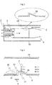
- Fig. 4 shows a configuration of a heat-transfer enhancement type combustion liner incorporated in the gas turbine combustor according to the second embodiment of the present invention.
- the gas turbine combustor according to the second embodiment includes a combustion liner 8 having a circularity recess 20 in a rectangular triangle shape formed on a partial area on the outer peripheral side of the combustion liner 8, the circularity recess 20 assuming a convex portion.
- the circularity recess 20 has a rectangular surface 25 downstream of the flowing direction of combustion air 2.
- the rectangular surface 25 has a plurality of holes of jet flow 21 arranged in a circumferential direction of the circularity recess 20, the holes of jet flow 21 each having a central axis extending in parallel with a central axis of the combustion liner 8. It is noted that, for convenience sake, Fig. 4 shows only one hole of jet flow 21.
- the gas turbine combustor according to the second embodiment of the present invention can also achieve effects substantially identical to those achieved by the gas turbine combustor according to the first embodiment described earlier.
- the combustion air 2 flowing through the holes of jet flow 21 forms an air layer on an inner peripheral surface of the circularity recess 20.
- the air layer further improves the cooling effect.
- the combustion air 2 that flows through the holes of jet flow 21 forms the air layer between a wall surface on the inner peripheral side of the circularity recess 20 and a circulating flow 31 at high temperature. This eliminates likelihood that the circulating flow 31 at high temperature will directly contact the wall surface on the inner peripheral side of the circularity recess 20, so that a greater cooling effect can be achieved at the circularity recess 20.
- a gas turbine combustor according to a third embodiment of the present invention will be described with reference to Figs. 5 and 6 .
- the gas turbine combustor according to the third embodiment is configured substantially identically to the gas turbine combustor according to the first embodiment except for the circularity recess and detailed descriptions for the identical portions will be omitted.
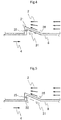
- Fig. 5 shows a configuration of a heat-transfer enhancement type combustion liner incorporated in the gas turbine combustor according to the third embodiment of the present invention.
- Fig. 6 is a configuration of another heat-transfer enhancement type combustion liner incorporated in the gas turbine combustor according to the third embodiment of the present invention.
- the gas turbine combustor according to the third embodiment includes a combustion liner 8 having a circularity recess 20 in a rectangular triangle shape formed on a partial area on the outer peripheral side of the combustion liner 8, the circularity recess 20 assuming a convex portion.
- the circularity recess 20 has a rectangular surface 25 downstream of the flowing direction of combustion air 2.
- the rectangular surface 25 has a plurality of holes of jet flow 22 arranged in a circumferential direction of the circularity recess 20, the holes of jet flow 22 each having a central axis inclined with respect to a central axis of the combustion liner 8.
- the gas turbine combustor according to the third embodiment of the present invention can also achieve effects substantially identical to those achieved by the gas turbine combustor according to the first embodiment described earlier.
- the combustion air 2 flowing through the inclined holes of jet flow 22 further improves the cooling effect on the inner peripheral surface of the circularity recess 20. Specifically, an action by the combustion air 2 flowing through the inclined holes of jet flow 22 to push out or destroy a circulating flow 31 produced in a concave portion on the inner peripheral side of the circularity recess 20 supplies the combustion air 2 at low temperature to the concave portion side at all times. This achieves an even greater cooling effect in the circularity recess 20.
- the rectangular surface 25 of the circularity recess 20 may have both the holes of jet flow 21, each having a central axis extending in parallel with the central axis of the combustion liner 8, and the holes of jet flow 22, each having a central axis inclined with respect to the central axis of the combustion liner 8.
- the gas turbine combustor according to the example being useful for the understanding of the present invention is configured substantially identically to the gas turbine combustor according to the first embodiment except for the circularity recess and its surrounding parts, and detailed descriptions for the identical portions will be omitted.
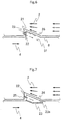
- Fig. 7 shows a configuration of a heat-transfer enhancement type combustion liner incorporated in the gas turbine combustor according to the example being useful for the understanding of the present invention although not forming part of the invention as defined by the claims.
- the gas turbine combustor includes an inclined plane 23 disposed at the circularity concave portion formed on the inner peripheral side of the combustion liner 8 through which the heating medium flows.
- the inclined plane 23 results in a circularity slit 23a being formed.
- the rectangular surface 25 of the circularity recess 20 has a plurality of holes of jet flow 22 arranged in the circumferential direction of the circularity recess 20, the holes of jet flow 22 each having a central axis inclined with respect to the central axis of the combustion liner 8.
- gas turbine combustor according to the example being useful for the understanding of the present invention can also achieve effects substantially identical to those achieved by the gas turbine combustor according to the first embodiment described earlier.
- the combustion air 2 flows through the inclined holes of jet flow 22 formed in the rectangular surface 25 of the circularity recess 20 into a space formed by the circularity concave portion and the slit 23a on the inner peripheral side of the combustion liner 8.
- This combustion air 2 cools the circularity recess 20 generally.
- air discharged from an opening in the slit 23a is formed into a film.
- a heat insulating action by the formation of the air film achieves an effect of protecting the combustion liner 8 from the high-temperature combustion gas 4 as the heating medium.
- the rectangular surface 25 of the circularity recess 20 has the holes of jet flow 22, each having a central axis inclined with respect to the central axis of the combustion liner 8.
- the rectangular surface 25 may have a plurality of holes of jet flow 21, each having a central axis extending in parallel with the central axis of the combustion liner 8.
- the gas turbine combustor according to another example useful for the understanding of the present invention is configured substantially identically to the gas turbine combustor according to the first embodiment except for the circularity recess and detailed descriptions for the identical portions will be omitted.
- Fig. 8 shows a configuration of a heat-transfer enhancement type combustion liner incorporated in the gas turbine combustor according to another example useful for the understanding of the present invention.
- the gas turbine combustor includes a combustion liner 8 having a rectangular circularity recess 24 formed on part of the combustion liner 8 and protruding from the outer peripheral surface of the combustion liner 8.
- the circularity recess 24 has a surface extending in parallel with the face of the combustion liner 8, the surface having a length longer than that of rectangular surfaces 25.
- part of combustion gas 4 flows into the circularity concave portion formed on the inner peripheral side of the combustion liner 8, which forms a circulating flow 31.
- This circulating flow 31 has a high temperature, but is slow in velocity, so that only a small amount of heat is transferred to the circularity recess 24.
- a boundary layer 32 of combustion air 2 is newly formed at a leading end corner of the rectangular surface 25 disposed upstream of the combustion air 2, the boundary layer 32 starting with the leading end corner of the rectangular surface 25.
- This boundary layer 32 of the combustion air 2 is extremely thin in the beginnings of its formation, exhibiting a tendency toward a better heat transfer characteristic.
- the layer thickness increases as the combustion air 2 moves toward the downstream side, resulting in a gradually degraded heat transfer characteristic.
- the amount of heat transferred from the circulating flow 31 as the heating medium is small at the circularity concave portion on the inner peripheral side of the combustion liner 8, but in contrast, the heat transfer characteristic improves at the convex portion of the circularity recess 24 protrusion on the outer peripheral side of the combustion liner 8. As a result, the cooling performance is generally improved.
- the shape of the rectangular surfaces 25 that constitute the rectangular convex portion of the circularity recess 24 has a structural characteristic identical to that achieved by the L-shaped annular rib as in the related art.
- the two rectangular surfaces 25 in the cross section of the circularity recess 24 further enhance stiffness, so that an effect of preventing damage by, for example, vibration can be further enhanced.
- a gas turbine combustor according to a fourth embodiment of the present invention will be described with reference to Fig. 9 .
- the gas turbine combustor according to the fourth embodiment is configured substantially identically to the gas turbine combustor according to the first embodiment except for the circularity recess and detailed descriptions for the identical portions will be omitted.
- Fig. 9 shows a configuration of a heat-transfer enhancement type combustion liner incorporated in the gas turbine combustor according to the fourth embodiment of the present invention.
- the gas turbine combustor according to the fourth embodiment includes a combustion liner 8 having a circularity recess 20a formed on a partial area on the outer peripheral side of the combustion liner 8, the circularity recess 20a having a cross section in a rectangular triangle shape serving as a convex on the outer peripheral side of the combustion liner 8.
- the circularity recess 20a has a rectangular surface 25 that faces upstream in the flowing direction of combustion air 2 and an oblique surface 26 that faces downstream in the flowing direction of the combustion air 2.
- the rectangular surface 25 has a plurality of holes of jet flow 21 arranged in a circumferential direction of the circularity recess 20a, the holes of jet flow 21 each having a central axis extending in parallel with the central axis of the combustion liner 8.
- the gas turbine combustor according to the fourth embodiment of the present invention can also achieve effects substantially identical to those achieved by the gas turbine combustor according to the first embodiment described earlier.
Landscapes
- Engineering & Computer Science (AREA)
- Chemical & Material Sciences (AREA)
- Combustion & Propulsion (AREA)
- Mechanical Engineering (AREA)
- General Engineering & Computer Science (AREA)
- Turbine Rotor Nozzle Sealing (AREA)
Applications Claiming Priority (1)
| Application Number | Priority Date | Filing Date | Title |
|---|---|---|---|
| JP2013229514A JP6246562B2 (ja) | 2013-11-05 | 2013-11-05 | ガスタービン燃焼器 |
Publications (2)
| Publication Number | Publication Date |
|---|---|
| EP2868971A1 EP2868971A1 (en) | 2015-05-06 |
| EP2868971B1 true EP2868971B1 (en) | 2021-01-06 |
Family
ID=51842438
Family Applications (1)
| Application Number | Title | Priority Date | Filing Date |
|---|---|---|---|
| EP14191424.2A Active EP2868971B1 (en) | 2013-11-05 | 2014-11-03 | Gas turbine combustor |
Country Status (4)
| Country | Link |
|---|---|
| US (1) | US10184662B2 (ja) |
| EP (1) | EP2868971B1 (ja) |
| JP (1) | JP6246562B2 (ja) |
| CN (1) | CN104613498B (ja) |
Families Citing this family (7)
| Publication number | Priority date | Publication date | Assignee | Title |
|---|---|---|---|---|
| US10337736B2 (en) * | 2015-07-24 | 2019-07-02 | Pratt & Whitney Canada Corp. | Gas turbine engine combustor and method of forming same |
| US10378444B2 (en) * | 2015-08-19 | 2019-08-13 | General Electric Company | Engine component for a gas turbine engine |
| US10260751B2 (en) | 2015-09-28 | 2019-04-16 | Pratt & Whitney Canada Corp. | Single skin combustor with heat transfer enhancement |
| US20180180289A1 (en) * | 2016-12-23 | 2018-06-28 | General Electric Company | Turbine engine assembly including a rotating detonation combustor |
| US10823414B2 (en) * | 2018-03-19 | 2020-11-03 | Raytheon Technologies Corporation | Hooded entrance to effusion holes |
| JP7132096B2 (ja) * | 2018-11-14 | 2022-09-06 | 三菱重工業株式会社 | ガスタービン燃焼器 |
| JP7550694B2 (ja) * | 2021-03-26 | 2024-09-13 | 本田技研工業株式会社 | ガスタービン用燃焼器 |
Citations (2)
| Publication number | Priority date | Publication date | Assignee | Title |
|---|---|---|---|---|
| EP1371906A2 (en) * | 2002-06-11 | 2003-12-17 | General Electric Company | Gas turbine engine combustor can with trapped vortex cavity |
| EP2500656A2 (en) * | 2011-03-15 | 2012-09-19 | General Electric Company | Gas turbine combustor having a fuel nozzle for flame anchoring |
Family Cites Families (23)
| Publication number | Priority date | Publication date | Assignee | Title |
|---|---|---|---|---|
| US4236378A (en) * | 1978-03-01 | 1980-12-02 | General Electric Company | Sectoral combustor for burning low-BTU fuel gas |
| US4242871A (en) * | 1979-09-18 | 1981-01-06 | United Technologies Corporation | Louver burner liner |
| US4380906A (en) | 1981-01-22 | 1983-04-26 | United Technologies Corporation | Combustion liner cooling scheme |
| US4622821A (en) * | 1985-01-07 | 1986-11-18 | United Technologies Corporation | Combustion liner for a gas turbine engine |
| US4875339A (en) * | 1987-11-27 | 1989-10-24 | General Electric Company | Combustion chamber liner insert |
| US4916906A (en) * | 1988-03-25 | 1990-04-17 | General Electric Company | Breach-cooled structure |
| US5361828A (en) * | 1993-02-17 | 1994-11-08 | General Electric Company | Scaled heat transfer surface with protruding ramp surface turbulators |
| JPH08254316A (ja) * | 1995-03-16 | 1996-10-01 | Toshiba Corp | ガスタービン燃焼器用ライナおよびその製造方法 |
| JP4134513B2 (ja) | 1997-09-12 | 2008-08-20 | 株式会社日立製作所 | ガスタービン燃焼器とそのライチ構造 |
| US6145319A (en) * | 1998-07-16 | 2000-11-14 | General Electric Company | Transitional multihole combustion liner |
| JP3967521B2 (ja) * | 2000-03-30 | 2007-08-29 | 株式会社日立製作所 | 伝熱装置及びその製造方法並びに伝熱装置を備えたガスタービン燃焼器 |
| US6568079B2 (en) * | 2001-06-11 | 2003-05-27 | General Electric Company | Methods for replacing combustor liner panels |
| US7007481B2 (en) | 2003-09-10 | 2006-03-07 | General Electric Company | Thick coated combustor liner |
| CN100504174C (zh) * | 2003-12-16 | 2009-06-24 | 株式会社日立制作所 | 燃气轮机用燃烧器 |
| DE102006026969A1 (de) * | 2006-06-09 | 2007-12-13 | Rolls-Royce Deutschland Ltd & Co Kg | Gasturbinenbrennkammerwand für eine mager-brennende Gasturbinenbrennkammer |
| EP2107314A1 (en) * | 2008-04-01 | 2009-10-07 | Siemens Aktiengesellschaft | Combustor for a gas turbine |
| US20120047895A1 (en) | 2010-08-26 | 2012-03-01 | General Electric Company | Systems and apparatus relating to combustor cooling and operation in gas turbine engines |
| JP5579011B2 (ja) * | 2010-10-05 | 2014-08-27 | 株式会社日立製作所 | ガスタービン燃焼器 |
| US8931280B2 (en) * | 2011-04-26 | 2015-01-13 | General Electric Company | Fully impingement cooled venturi with inbuilt resonator for reduced dynamics and better heat transfer capabilities |
| JP5438727B2 (ja) * | 2011-07-27 | 2014-03-12 | 株式会社日立製作所 | 燃焼器、バーナ及びガスタービン |
| GB201114745D0 (en) * | 2011-08-26 | 2011-10-12 | Rolls Royce Plc | Wall elements for gas turbine engines |
| US20130074507A1 (en) * | 2011-09-28 | 2013-03-28 | Karthick Kaleeswaran | Combustion liner for a turbine engine |
| JP6066065B2 (ja) | 2013-02-20 | 2017-01-25 | 三菱日立パワーシステムズ株式会社 | 伝熱装置を備えたガスタービン燃焼器 |
-
2013
- 2013-11-05 JP JP2013229514A patent/JP6246562B2/ja active Active
-
2014
- 2014-11-03 EP EP14191424.2A patent/EP2868971B1/en active Active
- 2014-11-03 CN CN201410608240.XA patent/CN104613498B/zh active Active
- 2014-11-03 US US14/531,253 patent/US10184662B2/en active Active
Patent Citations (2)
| Publication number | Priority date | Publication date | Assignee | Title |
|---|---|---|---|---|
| EP1371906A2 (en) * | 2002-06-11 | 2003-12-17 | General Electric Company | Gas turbine engine combustor can with trapped vortex cavity |
| EP2500656A2 (en) * | 2011-03-15 | 2012-09-19 | General Electric Company | Gas turbine combustor having a fuel nozzle for flame anchoring |
Also Published As
| Publication number | Publication date |
|---|---|
| JP6246562B2 (ja) | 2017-12-13 |
| EP2868971A1 (en) | 2015-05-06 |
| US10184662B2 (en) | 2019-01-22 |
| US20150121885A1 (en) | 2015-05-07 |
| CN104613498A (zh) | 2015-05-13 |
| CN104613498B (zh) | 2017-05-10 |
| JP2015090229A (ja) | 2015-05-11 |
Similar Documents
| Publication | Publication Date | Title |
|---|---|---|
| EP2868971B1 (en) | Gas turbine combustor | |
| US7007482B2 (en) | Combustion liner seal with heat transfer augmentation | |
| US5117624A (en) | Fuel injector nozzle support | |
| EP2613002B1 (en) | Methods and systems for cooling a transition nozzle | |
| JP2014132214A (ja) | 燃焼器に燃料を供給する燃料噴射器 | |
| EP2619507B1 (en) | Combustor with a single limited fuel-air mixing burner and recuperated micro gas turbine | |
| JP2005061823A (ja) | 改良型デフレクタプレートを有するガスタービンエンジンの燃焼器ドーム組立体 | |
| EP3988763A1 (en) | Impingement jet cooling structure with wavy channel | |
| US10890075B2 (en) | Turbine blade having squealer tip | |
| US20140352312A1 (en) | Injector for introducing a fuel-air mixture into a combustion chamber | |
| CN107191967B (zh) | 燃烧衬套冷却 | |
| US20160033134A1 (en) | Seal in combustor nozzle of gas turbine engine | |
| US11041623B2 (en) | Gas turbine combustor with heat exchanger between rich combustion zone and secondary combustion zone | |
| KR101911162B1 (ko) | 가스 터빈 연소기 | |
| KR20190036202A (ko) | 가스 터빈 블레이드 | |
| JP7132096B2 (ja) | ガスタービン燃焼器 | |
| KR20190083080A (ko) | 연소기의 냉각구조와 이를 포함하는 연소기 및 가스터빈 | |
| US10890328B2 (en) | Fin-pin flow guide for efficient transition piece cooling | |
| JP2001280154A (ja) | 伝熱装置及びその製造方法並びに伝熱装置を備えたガスタービン燃焼器 | |
| JPH10339440A (ja) | ガスタービン燃焼装置 | |
| US10669860B2 (en) | Gas turbine blade | |
| EP3220048B1 (en) | Combustion liner cooling | |
| US12055299B2 (en) | Combustor and gas turbine | |
| WO2023027116A1 (ja) | 燃焼器パネル、及びガスタービン用燃焼器 | |
| US20240191631A1 (en) | Turbine vane platform sealing assembly, and turbine vane and gas turbine including same |
Legal Events
| Date | Code | Title | Description |
|---|---|---|---|
| PUAI | Public reference made under article 153(3) epc to a published international application that has entered the european phase |
Free format text: ORIGINAL CODE: 0009012 |
|
| 17P | Request for examination filed |
Effective date: 20141219 |
|
| AK | Designated contracting states |
Kind code of ref document: A1 Designated state(s): AL AT BE BG CH CY CZ DE DK EE ES FI FR GB GR HR HU IE IS IT LI LT LU LV MC MK MT NL NO PL PT RO RS SE SI SK SM TR |
|
| AX | Request for extension of the european patent |
Extension state: BA ME |
|
| STAA | Information on the status of an ep patent application or granted ep patent |
Free format text: STATUS: EXAMINATION IS IN PROGRESS |
|
| 17Q | First examination report despatched |
Effective date: 20190920 |
|
| GRAP | Despatch of communication of intention to grant a patent |
Free format text: ORIGINAL CODE: EPIDOSNIGR1 |
|
| STAA | Information on the status of an ep patent application or granted ep patent |
Free format text: STATUS: GRANT OF PATENT IS INTENDED |
|
| INTG | Intention to grant announced |
Effective date: 20200710 |
|
| GRAS | Grant fee paid |
Free format text: ORIGINAL CODE: EPIDOSNIGR3 |
|
| RAP1 | Party data changed (applicant data changed or rights of an application transferred) |
Owner name: MITSUBISHI POWER, LTD. |
|
| RIN1 | Information on inventor provided before grant (corrected) |
Inventor name: TATSUMI, TESTUMA Inventor name: NUMATA, SHOHEI Inventor name: HIDAKA, MASATAKA Inventor name: YOKOTA, OSAMI |
|
| GRAA | (expected) grant |
Free format text: ORIGINAL CODE: 0009210 |
|
| STAA | Information on the status of an ep patent application or granted ep patent |
Free format text: STATUS: THE PATENT HAS BEEN GRANTED |
|
| AK | Designated contracting states |
Kind code of ref document: B1 Designated state(s): AL AT BE BG CH CY CZ DE DK EE ES FI FR GB GR HR HU IE IS IT LI LT LU LV MC MK MT NL NO PL PT RO RS SE SI SK SM TR |
|
| REG | Reference to a national code |
Ref country code: GB Ref legal event code: FG4D |
|
| REG | Reference to a national code |
Ref country code: AT Ref legal event code: REF Ref document number: 1352766 Country of ref document: AT Kind code of ref document: T Effective date: 20210115 Ref country code: CH Ref legal event code: EP |
|
| REG | Reference to a national code |
Ref country code: DE Ref legal event code: R096 Ref document number: 602014073948 Country of ref document: DE |
|
| REG | Reference to a national code |
Ref country code: IE Ref legal event code: FG4D |
|
| REG | Reference to a national code |
Ref country code: NL Ref legal event code: MP Effective date: 20210106 |
|
| REG | Reference to a national code |
Ref country code: AT Ref legal event code: MK05 Ref document number: 1352766 Country of ref document: AT Kind code of ref document: T Effective date: 20210106 |
|
| REG | Reference to a national code |
Ref country code: LT Ref legal event code: MG9D |
|
| PG25 | Lapsed in a contracting state [announced via postgrant information from national office to epo] |
Ref country code: NO Free format text: LAPSE BECAUSE OF FAILURE TO SUBMIT A TRANSLATION OF THE DESCRIPTION OR TO PAY THE FEE WITHIN THE PRESCRIBED TIME-LIMIT Effective date: 20210406 Ref country code: NL Free format text: LAPSE BECAUSE OF FAILURE TO SUBMIT A TRANSLATION OF THE DESCRIPTION OR TO PAY THE FEE WITHIN THE PRESCRIBED TIME-LIMIT Effective date: 20210106 Ref country code: BG Free format text: LAPSE BECAUSE OF FAILURE TO SUBMIT A TRANSLATION OF THE DESCRIPTION OR TO PAY THE FEE WITHIN THE PRESCRIBED TIME-LIMIT Effective date: 20210406 Ref country code: FI Free format text: LAPSE BECAUSE OF FAILURE TO SUBMIT A TRANSLATION OF THE DESCRIPTION OR TO PAY THE FEE WITHIN THE PRESCRIBED TIME-LIMIT Effective date: 20210106 Ref country code: HR Free format text: LAPSE BECAUSE OF FAILURE TO SUBMIT A TRANSLATION OF THE DESCRIPTION OR TO PAY THE FEE WITHIN THE PRESCRIBED TIME-LIMIT Effective date: 20210106 Ref country code: GR Free format text: LAPSE BECAUSE OF FAILURE TO SUBMIT A TRANSLATION OF THE DESCRIPTION OR TO PAY THE FEE WITHIN THE PRESCRIBED TIME-LIMIT Effective date: 20210407 Ref country code: PT Free format text: LAPSE BECAUSE OF FAILURE TO SUBMIT A TRANSLATION OF THE DESCRIPTION OR TO PAY THE FEE WITHIN THE PRESCRIBED TIME-LIMIT Effective date: 20210506 Ref country code: LT Free format text: LAPSE BECAUSE OF FAILURE TO SUBMIT A TRANSLATION OF THE DESCRIPTION OR TO PAY THE FEE WITHIN THE PRESCRIBED TIME-LIMIT Effective date: 20210106 |
|
| PG25 | Lapsed in a contracting state [announced via postgrant information from national office to epo] |
Ref country code: SE Free format text: LAPSE BECAUSE OF FAILURE TO SUBMIT A TRANSLATION OF THE DESCRIPTION OR TO PAY THE FEE WITHIN THE PRESCRIBED TIME-LIMIT Effective date: 20210106 Ref country code: AT Free format text: LAPSE BECAUSE OF FAILURE TO SUBMIT A TRANSLATION OF THE DESCRIPTION OR TO PAY THE FEE WITHIN THE PRESCRIBED TIME-LIMIT Effective date: 20210106 Ref country code: LV Free format text: LAPSE BECAUSE OF FAILURE TO SUBMIT A TRANSLATION OF THE DESCRIPTION OR TO PAY THE FEE WITHIN THE PRESCRIBED TIME-LIMIT Effective date: 20210106 Ref country code: PL Free format text: LAPSE BECAUSE OF FAILURE TO SUBMIT A TRANSLATION OF THE DESCRIPTION OR TO PAY THE FEE WITHIN THE PRESCRIBED TIME-LIMIT Effective date: 20210106 Ref country code: RS Free format text: LAPSE BECAUSE OF FAILURE TO SUBMIT A TRANSLATION OF THE DESCRIPTION OR TO PAY THE FEE WITHIN THE PRESCRIBED TIME-LIMIT Effective date: 20210106 |
|
| PG25 | Lapsed in a contracting state [announced via postgrant information from national office to epo] |
Ref country code: IS Free format text: LAPSE BECAUSE OF FAILURE TO SUBMIT A TRANSLATION OF THE DESCRIPTION OR TO PAY THE FEE WITHIN THE PRESCRIBED TIME-LIMIT Effective date: 20210506 |
|
| REG | Reference to a national code |
Ref country code: DE Ref legal event code: R097 Ref document number: 602014073948 Country of ref document: DE |
|
| PG25 | Lapsed in a contracting state [announced via postgrant information from national office to epo] |
Ref country code: SM Free format text: LAPSE BECAUSE OF FAILURE TO SUBMIT A TRANSLATION OF THE DESCRIPTION OR TO PAY THE FEE WITHIN THE PRESCRIBED TIME-LIMIT Effective date: 20210106 Ref country code: EE Free format text: LAPSE BECAUSE OF FAILURE TO SUBMIT A TRANSLATION OF THE DESCRIPTION OR TO PAY THE FEE WITHIN THE PRESCRIBED TIME-LIMIT Effective date: 20210106 Ref country code: CZ Free format text: LAPSE BECAUSE OF FAILURE TO SUBMIT A TRANSLATION OF THE DESCRIPTION OR TO PAY THE FEE WITHIN THE PRESCRIBED TIME-LIMIT Effective date: 20210106 |
|
| PLBE | No opposition filed within time limit |
Free format text: ORIGINAL CODE: 0009261 |
|
| STAA | Information on the status of an ep patent application or granted ep patent |
Free format text: STATUS: NO OPPOSITION FILED WITHIN TIME LIMIT |
|
| PG25 | Lapsed in a contracting state [announced via postgrant information from national office to epo] |
Ref country code: DK Free format text: LAPSE BECAUSE OF FAILURE TO SUBMIT A TRANSLATION OF THE DESCRIPTION OR TO PAY THE FEE WITHIN THE PRESCRIBED TIME-LIMIT Effective date: 20210106 Ref country code: ES Free format text: LAPSE BECAUSE OF FAILURE TO SUBMIT A TRANSLATION OF THE DESCRIPTION OR TO PAY THE FEE WITHIN THE PRESCRIBED TIME-LIMIT Effective date: 20210106 Ref country code: SK Free format text: LAPSE BECAUSE OF FAILURE TO SUBMIT A TRANSLATION OF THE DESCRIPTION OR TO PAY THE FEE WITHIN THE PRESCRIBED TIME-LIMIT Effective date: 20210106 Ref country code: RO Free format text: LAPSE BECAUSE OF FAILURE TO SUBMIT A TRANSLATION OF THE DESCRIPTION OR TO PAY THE FEE WITHIN THE PRESCRIBED TIME-LIMIT Effective date: 20210106 |
|
| 26N | No opposition filed |
Effective date: 20211007 |
|
| PG25 | Lapsed in a contracting state [announced via postgrant information from national office to epo] |
Ref country code: AL Free format text: LAPSE BECAUSE OF FAILURE TO SUBMIT A TRANSLATION OF THE DESCRIPTION OR TO PAY THE FEE WITHIN THE PRESCRIBED TIME-LIMIT Effective date: 20210106 |
|
| PG25 | Lapsed in a contracting state [announced via postgrant information from national office to epo] |
Ref country code: SI Free format text: LAPSE BECAUSE OF FAILURE TO SUBMIT A TRANSLATION OF THE DESCRIPTION OR TO PAY THE FEE WITHIN THE PRESCRIBED TIME-LIMIT Effective date: 20210106 |
|
| PG25 | Lapsed in a contracting state [announced via postgrant information from national office to epo] |
Ref country code: IT Free format text: LAPSE BECAUSE OF FAILURE TO SUBMIT A TRANSLATION OF THE DESCRIPTION OR TO PAY THE FEE WITHIN THE PRESCRIBED TIME-LIMIT Effective date: 20210106 |
|
| PG25 | Lapsed in a contracting state [announced via postgrant information from national office to epo] |
Ref country code: IS Free format text: LAPSE BECAUSE OF FAILURE TO SUBMIT A TRANSLATION OF THE DESCRIPTION OR TO PAY THE FEE WITHIN THE PRESCRIBED TIME-LIMIT Effective date: 20210506 |
|
| PG25 | Lapsed in a contracting state [announced via postgrant information from national office to epo] |
Ref country code: MC Free format text: LAPSE BECAUSE OF FAILURE TO SUBMIT A TRANSLATION OF THE DESCRIPTION OR TO PAY THE FEE WITHIN THE PRESCRIBED TIME-LIMIT Effective date: 20210106 |
|
| REG | Reference to a national code |
Ref country code: CH Ref legal event code: PL |
|
| GBPC | Gb: european patent ceased through non-payment of renewal fee |
Effective date: 20211103 |
|
| PG25 | Lapsed in a contracting state [announced via postgrant information from national office to epo] |
Ref country code: LU Free format text: LAPSE BECAUSE OF NON-PAYMENT OF DUE FEES Effective date: 20211103 Ref country code: BE Free format text: LAPSE BECAUSE OF NON-PAYMENT OF DUE FEES Effective date: 20211130 |
|
| REG | Reference to a national code |
Ref country code: BE Ref legal event code: MM Effective date: 20211130 |
|
| PG25 | Lapsed in a contracting state [announced via postgrant information from national office to epo] |
Ref country code: LI Free format text: LAPSE BECAUSE OF NON-PAYMENT OF DUE FEES Effective date: 20211130 Ref country code: CH Free format text: LAPSE BECAUSE OF NON-PAYMENT OF DUE FEES Effective date: 20211130 |
|
| PG25 | Lapsed in a contracting state [announced via postgrant information from national office to epo] |
Ref country code: IE Free format text: LAPSE BECAUSE OF NON-PAYMENT OF DUE FEES Effective date: 20211103 Ref country code: GB Free format text: LAPSE BECAUSE OF NON-PAYMENT OF DUE FEES Effective date: 20211103 |
|
| PG25 | Lapsed in a contracting state [announced via postgrant information from national office to epo] |
Ref country code: FR Free format text: LAPSE BECAUSE OF NON-PAYMENT OF DUE FEES Effective date: 20211130 |
|
| PG25 | Lapsed in a contracting state [announced via postgrant information from national office to epo] |
Ref country code: HU Free format text: LAPSE BECAUSE OF FAILURE TO SUBMIT A TRANSLATION OF THE DESCRIPTION OR TO PAY THE FEE WITHIN THE PRESCRIBED TIME-LIMIT; INVALID AB INITIO Effective date: 20141103 |
|
| PG25 | Lapsed in a contracting state [announced via postgrant information from national office to epo] |
Ref country code: CY Free format text: LAPSE BECAUSE OF FAILURE TO SUBMIT A TRANSLATION OF THE DESCRIPTION OR TO PAY THE FEE WITHIN THE PRESCRIBED TIME-LIMIT Effective date: 20210106 |
|
| PGFP | Annual fee paid to national office [announced via postgrant information from national office to epo] |
Ref country code: DE Payment date: 20230929 Year of fee payment: 10 |
|
| PG25 | Lapsed in a contracting state [announced via postgrant information from national office to epo] |
Ref country code: MK Free format text: LAPSE BECAUSE OF FAILURE TO SUBMIT A TRANSLATION OF THE DESCRIPTION OR TO PAY THE FEE WITHIN THE PRESCRIBED TIME-LIMIT Effective date: 20210106 |
|
| PG25 | Lapsed in a contracting state [announced via postgrant information from national office to epo] |
Ref country code: TR Free format text: LAPSE BECAUSE OF FAILURE TO SUBMIT A TRANSLATION OF THE DESCRIPTION OR TO PAY THE FEE WITHIN THE PRESCRIBED TIME-LIMIT Effective date: 20210106 |