EP2868285A1 - Elektrochirurgische Systeme und Verfahren zur Überwachung der Stromdosierung - Google Patents
Elektrochirurgische Systeme und Verfahren zur Überwachung der Stromdosierung Download PDFInfo
- Publication number
- EP2868285A1 EP2868285A1 EP20140185328 EP14185328A EP2868285A1 EP 2868285 A1 EP2868285 A1 EP 2868285A1 EP 20140185328 EP20140185328 EP 20140185328 EP 14185328 A EP14185328 A EP 14185328A EP 2868285 A1 EP2868285 A1 EP 2868285A1
- Authority
- EP
- European Patent Office
- Prior art keywords
- waveform
- analog
- real
- voltage
- power
- Prior art date
- Legal status (The legal status is an assumption and is not a legal conclusion. Google has not performed a legal analysis and makes no representation as to the accuracy of the status listed.)
- Granted
Links
Images


Classifications
-
- A—HUMAN NECESSITIES
- A61—MEDICAL OR VETERINARY SCIENCE; HYGIENE
- A61B—DIAGNOSIS; SURGERY; IDENTIFICATION
- A61B18/00—Surgical instruments, devices or methods for transferring non-mechanical forms of energy to or from the body
- A61B18/04—Surgical instruments, devices or methods for transferring non-mechanical forms of energy to or from the body by heating
- A61B18/12—Surgical instruments, devices or methods for transferring non-mechanical forms of energy to or from the body by heating by passing a current through the tissue to be heated, e.g. high-frequency current
- A61B18/1206—Generators therefor
- A61B18/1233—Generators therefor with circuits for assuring patient safety
-
- A—HUMAN NECESSITIES
- A61—MEDICAL OR VETERINARY SCIENCE; HYGIENE
- A61B—DIAGNOSIS; SURGERY; IDENTIFICATION
- A61B18/00—Surgical instruments, devices or methods for transferring non-mechanical forms of energy to or from the body
- A61B18/04—Surgical instruments, devices or methods for transferring non-mechanical forms of energy to or from the body by heating
- A61B18/12—Surgical instruments, devices or methods for transferring non-mechanical forms of energy to or from the body by heating by passing a current through the tissue to be heated, e.g. high-frequency current
- A61B18/1206—Generators therefor
-
- A—HUMAN NECESSITIES
- A61—MEDICAL OR VETERINARY SCIENCE; HYGIENE
- A61B—DIAGNOSIS; SURGERY; IDENTIFICATION
- A61B18/00—Surgical instruments, devices or methods for transferring non-mechanical forms of energy to or from the body
- A61B2018/00571—Surgical instruments, devices or methods for transferring non-mechanical forms of energy to or from the body for achieving a particular surgical effect
- A61B2018/00577—Ablation
-
- A—HUMAN NECESSITIES
- A61—MEDICAL OR VETERINARY SCIENCE; HYGIENE
- A61B—DIAGNOSIS; SURGERY; IDENTIFICATION
- A61B18/00—Surgical instruments, devices or methods for transferring non-mechanical forms of energy to or from the body
- A61B2018/00571—Surgical instruments, devices or methods for transferring non-mechanical forms of energy to or from the body for achieving a particular surgical effect
- A61B2018/00589—Coagulation
-
- A—HUMAN NECESSITIES
- A61—MEDICAL OR VETERINARY SCIENCE; HYGIENE
- A61B—DIAGNOSIS; SURGERY; IDENTIFICATION
- A61B18/00—Surgical instruments, devices or methods for transferring non-mechanical forms of energy to or from the body
- A61B2018/00571—Surgical instruments, devices or methods for transferring non-mechanical forms of energy to or from the body for achieving a particular surgical effect
- A61B2018/00601—Cutting
-
- A—HUMAN NECESSITIES
- A61—MEDICAL OR VETERINARY SCIENCE; HYGIENE
- A61B—DIAGNOSIS; SURGERY; IDENTIFICATION
- A61B18/00—Surgical instruments, devices or methods for transferring non-mechanical forms of energy to or from the body
- A61B2018/00571—Surgical instruments, devices or methods for transferring non-mechanical forms of energy to or from the body for achieving a particular surgical effect
- A61B2018/0063—Sealing
-
- A—HUMAN NECESSITIES
- A61—MEDICAL OR VETERINARY SCIENCE; HYGIENE
- A61B—DIAGNOSIS; SURGERY; IDENTIFICATION
- A61B18/00—Surgical instruments, devices or methods for transferring non-mechanical forms of energy to or from the body
- A61B2018/00636—Sensing and controlling the application of energy
- A61B2018/00642—Sensing and controlling the application of energy with feedback, i.e. closed loop control
- A61B2018/00648—Sensing and controlling the application of energy with feedback, i.e. closed loop control using more than one sensed parameter
-
- A—HUMAN NECESSITIES
- A61—MEDICAL OR VETERINARY SCIENCE; HYGIENE
- A61B—DIAGNOSIS; SURGERY; IDENTIFICATION
- A61B18/00—Surgical instruments, devices or methods for transferring non-mechanical forms of energy to or from the body
- A61B2018/00636—Sensing and controlling the application of energy
- A61B2018/00696—Controlled or regulated parameters
- A61B2018/00702—Power or energy
-
- A—HUMAN NECESSITIES
- A61—MEDICAL OR VETERINARY SCIENCE; HYGIENE
- A61B—DIAGNOSIS; SURGERY; IDENTIFICATION
- A61B18/00—Surgical instruments, devices or methods for transferring non-mechanical forms of energy to or from the body
- A61B2018/00636—Sensing and controlling the application of energy
- A61B2018/00773—Sensed parameters
- A61B2018/00779—Power or energy
-
- A—HUMAN NECESSITIES
- A61—MEDICAL OR VETERINARY SCIENCE; HYGIENE
- A61B—DIAGNOSIS; SURGERY; IDENTIFICATION
- A61B18/00—Surgical instruments, devices or methods for transferring non-mechanical forms of energy to or from the body
- A61B2018/00636—Sensing and controlling the application of energy
- A61B2018/00773—Sensed parameters
- A61B2018/00827—Current
-
- A—HUMAN NECESSITIES
- A61—MEDICAL OR VETERINARY SCIENCE; HYGIENE
- A61B—DIAGNOSIS; SURGERY; IDENTIFICATION
- A61B18/00—Surgical instruments, devices or methods for transferring non-mechanical forms of energy to or from the body
- A61B2018/00636—Sensing and controlling the application of energy
- A61B2018/00773—Sensed parameters
- A61B2018/00869—Phase
-
- A—HUMAN NECESSITIES
- A61—MEDICAL OR VETERINARY SCIENCE; HYGIENE
- A61B—DIAGNOSIS; SURGERY; IDENTIFICATION
- A61B18/00—Surgical instruments, devices or methods for transferring non-mechanical forms of energy to or from the body
- A61B2018/00636—Sensing and controlling the application of energy
- A61B2018/00773—Sensed parameters
- A61B2018/00892—Voltage
Definitions
- the present disclosure generally relates to electrosurgery. More particularly, the present disclosure relates to electrosurgical systems and methods for monitoring power dosage of electrosurgical energy delivered to tissue.
- Electrosurgery involves the application of high-frequency electric current to cut or modify biological tissue during an electrosurgical operation. Electrosurgery is performed using an electrosurgical generator, an active electrode, and a return electrode.
- the electrosurgical generator also referred to as a power supply or waveform generator
- the AC typically has a frequency above 100 kilohertz (kHz) to avoid muscle and/or nerve stimulation.
- the AC generated by the electrosurgical generator is conducted through tissue disposed between the active and return electrodes.
- the electrical energy (also referred to as electrosurgical energy) delivered to the tissue is converted into heat due to the resistivity of the tissue, which causes the tissue temperature to rise.
- the electrosurgical generator monitors the dosage of power (i.e., electrical energy per time) to control the heating of the tissue. Although many other variables affect the total heating of the tissue, increased current density and resistance of the tissue usually lead to increased heating.
- the electrosurgical energy is typically used for cutting, dissecting, ablating, coagulating, and/or sealing tissue.
- the two basic types of electrosurgery employed are monopolar and bipolar electrosurgery. Both of these types of electrosurgery use an active electrode and a return electrode.
- bipolar electrosurgery the surgical instrument includes an active electrode and a return electrode on the same instrument or in very close proximity to one another, which cause current to flow through a small amount of tissue.
- the return electrode is located elsewhere on the patient's body and is typically not a part of the electrosurgical instrument itself.
- the return electrode is part of a device typically referred to as a return pad.
- An electrosurgical generator makes use of voltage and current sensors to measure quantities, such as power, for controlling the output of the electrosurgical generator to achieve a desired clinical effect.
- a cable which may be more than a meter in length, connects the electrosurgical generator to the active and return electrodes and is used to deliver electrosurgical energy to tissue being treated.
- the cable creates a circuit network between the voltage and current sensors and the tissue being treated, which distorts the voltage and current waveforms generated by the electrosurgical generator so that the waveforms deviate from the desired pure sinusoidal, rectangular, sawtooth, pulse, triangular, or blended waveforms commonly used for electrosurgery.
- many generators employ compensation algorithms that account for the impedance of the circuit network of the cable.
- the electrosurgical systems and methods of the present disclosure monitor power dosage delivered to tissue being treated with improved speed and accuracy.
- the electrosurgical systems and methods use analog filters for sensor and/or cable compensation.
- the electrosurgical systems include an output stage, sensors, analog all-pass filters, an analog multiplier, an average power calculation circuit, and a controller.
- the output stage generates electrosurgical energy to treat the tissue.
- the sensors sense voltage and current waveforms of the generated electrosurgical energy.
- the analog all-pass filters filter the sensed voltage and current waveforms.
- the plurality of analog all-pass filter may have a lagging or leading phase.
- the analog multiplier multiplies the filtered voltage and current waveforms to obtain a real power waveform.
- the average power calculation circuit calculates a real average power based on the real power waveform.
- the controller then generates a control signal to control the output stage based on the real average power.
- the average power calculation circuit may include an analog integrator, an analog-to-digital (ADC), and a digital averaging filter.
- the analog integrator integrates the real power waveform.
- the ADC converts the integrated real power waveform into digital power waveform data.
- the digital averaging filter calculates the real average power based on the digital power waveform data.
- the digital averaging filter may be a moving average filter and be a finite or infinite impulse response filter.
- the average power calculation circuit may include an analog low pass filter, an ADC, and a digital integrator.
- the analog low pass filter filters the real power waveform and the ADC digitally samples the filtered power waveform into digital power waveform data.
- the digital integrator integrates the digital power waveform data to calculate the real average power.
- the analog all-pass filters includes a resistor and a capacitor to compensate for the phase difference between the voltage and current waveforms.
- the resistor may be a variable resistor configured to allow continuous adjustment of the phase difference between the voltage and current waveforms.
- the resistance value of the resistor may be varied based on the frequency of the voltage or current waveform and/or the properties of the electrosurgical cable.
- the all-pass filters may be designed such that the outputs from the all-pass filters have a substantially zero phase difference between sensed voltage and current waveforms.
- the plurality of analog all-pass filters may be first-order all-pass filters or second order all-pass filters.
- the second-order all-pass filter may include at least one bandpass filter which can be a multiple feedback bandpass filter, dual amplifier bandpass filter, or biquad filter.
- the average power calculation circuit includes a digital overlapping filter.
- a circuit network between the sensors and the tissue being treated is created by circuitry of the electrosurgical generator and a cable connecting an electrosurgical instrument and the electrosurgical generator, wherein the all pass filters include a phase delay and/or gain designed/configured to compensate for phase shift and/or gain inaccuracy by the circuit network.
- the present disclosure in another aspect, features a method for controlling an electrosurgical generator.
- the method includes generating electrosurgical energy, sensing a voltage waveform and a current waveform of the generated electrosurgical energy, filtering the sensed voltage and current waveforms by analog all-pass filters, multiplying the filtered voltage and current waveforms to obtain a real power waveform, calculating a real average power based on the real power waveform, and generating a control signal to control the output stage based on the real average power.
- the present disclosure in another aspect, features a non-transitory computer-readable medium storing instructions that, when executed by a processor, implement a method for controlling an electrosurgical generator.
- the method includes generating electrosurgical energy, sensing a voltage waveform and a current waveform of the generated electrosurgical energy, filtering the sensed voltage and current waveforms by analog all-pass filters, multiplying the filtered voltage and current waveforms to obtain a real power waveform, calculating a real average power based on the real power waveform, and generating a control signal to control the output stage based on the real average power.
- the electrosurgical generator circuitry and the cable in an electrosurgical system create a circuit network between the voltage and current sensors and the tissue being treated, which causes inaccurate power and impedance measurements.
- many generators employ compensation algorithms that account for the impedance of the circuit network.
- These compensation algorithms involve the measurement and storage of multiple cable parameters, such as series inductance, shunt capacitance, and resistance, which are used as constants in the solutions to the circuit network.
- the compensation algorithms also involve many mathematical operations, e.g., multiplies and additions, on complex numbers having real and imaginary components.
- the electrosurgical systems and methods of the present disclosure reduce the amount of memory and processing power needed to accurately measure real average power actually delivered to the tissue.
- the systems and methods according to the present disclosure use analog all-pass filters having leading or lagging phase to compensate for distortions caused by the circuit network so that the measured voltage and current can more accurately represent the actual voltage and current delivered to the tissue.
- FIG. 1 illustrates an electrosurgical system 100 in accordance with embodiments of the present disclosure.
- the electrosurgical system 100 includes an electrosurgical generator 102 which generates electrosurgical energy to treat tissue of a patient.
- the electrosurgical generator 102 generates an appropriate level of electrosurgical energy based on the selected mode of operation (e.g., cutting, coagulating, ablating, or sealing) and/or the sensed voltage and current waveforms of the generated electrosurgical energy.
- the electrosurgical system 100 may also include output connectors corresponding to a variety of electrosurgical instruments.
- the electrosurgical system 100 further includes a monopolar electrosurgical instrument 110 having an electrode for treating tissue of the patient (e.g., an electrosurgical cutting probe or ablation electrode) with a return pad 120.
- the monopolar electrosurgical instrument 110 can be connected to the electrosurgical generator 102 via one of the output connectors.
- the electrosurgical generator 102 may generate electrosurgical energy in the form of radio frequency (RF) energy.
- RF radio frequency
- the electrosurgical energy is supplied to the monopolar electrosurgical instrument 110, which applies the electrosurgical energy to tissue.
- the electrosurgical energy is returned to the electrosurgical generator 102 through the return pad 120.
- the return pad 120 provides sufficient contact area with the patient's tissue so as to minimize the risk of tissue damage due to the electrosurgical energy applied to the tissue.
- the electrosurgical system 100 also includes a bipolar electrosurgical instrument 130.
- the bipolar electrosurgical instrument 130 can be connected to the electrosurgical generator 102 via one of the output connectors.
- the electrosurgical energy is supplied to one of the two forceps, is applied to tissue, and is returned to the electrosurgical generator 102 through the other forceps.
- the electrosurgical generator 102 may be any suitable type of generator and may include output connectors to accommodate various types of electrosurgical instruments (e.g., monopolar electrosurgical instrument 110 and bipolar electrosurgical instrument 130).
- the electrosurgical generator 102 may also be configured to operate in a variety of modes, such as ablation, cutting, coagulation, and sealing.
- the electrosurgical generator 102 may include a switching mechanism (e.g., relays) to switch the supply of RF energy among the output connectors to which various electrosurgical instruments may be connected. For example, when an electrosurgical instrument 110 is connected to the electrosurgical generator 102, the switching mechanism switches the supply of RF energy to the monopolar plug.
- the electrosurgical generator 102 may be configured to provide RF energy to a plurality instruments simultaneously.
- the electrosurgical generator 102 includes a user interface having suitable user controls (e.g., buttons, activators, switches, or touch screens) for providing control parameters to the electrosurgical generator 102. These controls allow the user to adjust parameters of the electrosurgical energy (e.g., the power level or the shape of the output waveform) so that the electrosurgical energy is suitable for a particular surgical procedure (e.g., coagulating, ablating, tissue sealing, or cutting).
- the electrosurgical instruments 110 and 130 may also include user controls.
- the electrosurgical generator 102 may include one or more display screens for displaying a variety of information related to the operation of the electrosurgical generator 102 (e.g., intensity settings and treatment complete indicators).
- FIG. 2 is a block circuit diagram of the electrosurgical generator 102 of FIG. 1 .
- the electrosurgical generator 102 includes a generator circuit 200, which is connected to a cable 275 of an electrosurgical instrument 280 that delivers electrosurgical energy to treat tissue 290.
- the generator circuit 200 includes a high voltage power supply (HVPS) 210, a radio frequency (RF) output stage 220, voltage and current sensors 225, an analog signal processing circuit 230, analog-to-digital converters (ADCs) 240, a controller 250, a user interface (UI) 260, and a pulse width modulation controller 270.
- HVPS high voltage power supply
- RF radio frequency
- ADCs analog-to-digital converters
- the generator circuit 200 is configured to connect to an AC power source, such as a power outlet, which generates AC having a low frequency (e.g., 50 Hz or 60 Hz).
- the AC power source provides AC power to the generator circuit 200, which converts the low frequency AC to higher frequency AC that is suitable for a desired electrosurgical procedure.
- the HVPS 210 and the RF output stage 220 convert the AC having a low frequency to direct current and then invert the DC to AC having a high frequency.
- the generated AC waveform has a frequency suitable for an electrosurgical procedure (e.g., 472 kHz, 200 kHz, and 390 kHz).
- the appropriate frequency for the electrosurgical energy may differ based on the electrosurgical procedures and modes of electrosurgery. For example, nerve and muscle stimulations cease at about 100,000 cycles per second (100 kHz) and some electrosurgical procedures can be performed safely at a radio frequency (RF) above 100 kHz. At frequencies over 100 kHz, the electrosurgical energy can pass through a patient to targeted tissue with minimal neuromuscular stimulation. For example, ablation uses a frequency of 472 kHz. Other electrosurgical procedures can be performed at frequencies lower than 472 kHz, e.g., 200 kHz or 390 kHz, with minimal risk of damaging nerves and muscles.
- the HVPS 210 and the RF output stage 220 can provide AC signals with various frequencies suitable for electrosurgical operations.
- the RF output stage 220 may include a resonant tank circuit that matches the impedance at the RF output stage 220 to the impedance of the cable 275 and the tissue 290 so that there is a maximum or optimum power transfer from the electrosurgical generator 102 to the tissue 290.
- the plurality of voltage and current sensors 225 sense the AC voltage and current waveforms generated by the HVPS 210 and the RF output stage 220.
- the plurality of sensors 220 are coupled to the RF output stage 220 and the cable 275 to sense the voltage and current output from the generator circuit 200 to the cable 275.
- voltage sensors measure voltage across the two output connecting wires of the RF output stage 220 to the cable 275 and current sensors measure current passing through at least one output connecting wire of the RF output stage 220 to the cable 275.
- the plurality of sensors 225 may include two or more pairs or sets of voltage and current sensors that provide redundant measurements of the voltage and current waveforms. This redundancy ensures the reliability, accuracy, and stability of the voltage and current measurements at the output of the RF output stage 220.
- the sensors 225 may include fewer or more sets of voltage and current sensors depending on the application or the design requirements.
- the current and voltage sensed by the sensors 230 are not the same as the current and voltage delivered to the tissue 290 because the cable 275 introduces an impedance between the sensors 230 and the tissue 290 and/or because the voltage and current sensors themselves have inaccuracies.
- the sensed voltage and current waveforms are provided to the analog signal processing circuit 230 which differentially phase-compensates for the impedance of the cable and/or the sensor inaccuracies.
- the analog signal processing circuit 230 outputs an analog power waveform, as described in more detail below.
- the analog power waveform is then sampled by the ADCs 240 to obtain digital samples of the power waveform.
- the plurality of ADCs 240 may sample the analog power waveform at a frequency that is an integer multiple of the frequency of the voltage and current waveforms generated by the RF output stage 220.
- the digital samples of the power waveform are provided to the controller 250.
- the controller 250 includes a power dosage monitor 255 that receives the digital samples of the power waveform from the ADCs 240 and determines the real average power delivered to the tissue 290 being treated.
- the controller 250 compares the measured real average power with a power profile specific for an electrosurgical operation and generates a control signal to the PWM controller 270.
- the PWM controller 270 then generates a PWM signal having a desired duty cycle to control the output of the RF output stage 220.
- the controller 260 also receives input from the user interface (UI) 270.
- a user may set an electrosurgical operation mode (e.g., cutting, coagulating, ablating, or sealing) and corresponding electrosurgical signal type (e.g., pure sinusoidal, rectangular, sawtooth, pulse, triangular, or blended waveforms) via the UI 270.
- the UI 270 is not limited to setting the above features but allows a user to select a type of electrosurgical procedure (e.g., monopolar or bipolar), or to input desired control parameters for the electrosurgical procedure or the mode.
- the controller 250 may incorporate the inputs from the UI 270 to select an appropriate power profile and to generate a control signal.
- FIG. 3 is a circuit diagram of an impedance model of the cable 275 of FIG. 2 .
- the plurality of sensors sense voltage V sense 310 and current I sense 320.
- the cable 275 has an impedance Z cable 330 that includes a resistance R cable 332, an inductance L cable 334, and a shunt capacitance C cable 336.
- the tissue 290 is resistive in typical electrosurgical procedures and thus is modeled as a load resistance R load 340.
- One of the sensors 230 sense current I sense 320 passing through the supply line or return line of the electrosurgical generator 102 and another one of the sensors 230 senses voltage V sense 310 across the supply and return lines of the electrosurgical generator 102.
- the sensed voltage V sense 310 drops across the cable resistance R cable 332.
- the current I sense 320 is divided into shunt current I shunt 344 passing through the shunt capacitance C cable 236 and load current I load 342 passing through the load resistance R load 340.
- the sensed current I sense 320 is different from the current passing through the tissue load resistance R load 340.
- the sensed voltage V sense 310 is different from the voltage across the tissue load resistance R load 340 due to the cable resistance R cable 332 and the cable inductance L cable 334. It follows that power calculated from the sensed voltage and current waveforms is also different from the actual power delivered to the tissue.
- the impedance of the cable, Z cable 330 also distorts the phase of the sensed voltage and current waveforms so that the power calculated from the sensed voltage and current waveforms has a complex value having a real part and an imaginary part.
- the real part of the complex power may be considered the power delivered to the tissue R load 340.
- the sensors may distort the phase and magnitude of the voltage and current.
- the systems and methods of the present disclosure employ cable and sensor compensation techniques to accurately measure the real part of the power sensed by the sensors 225, which may represent the power delivered to the tissue. These cable and sensor compensation techniques compensate for the phase difference between the sensed voltage and current waveforms by using all-pass filters.
- FIGS. 4A-4C are circuit block diagrams of power monitoring circuits for monitoring power dosage according to embodiments of the present disclosure. These circuit block diagrams include analog circuits, analog-to-digital converters (ADCs), and digital circuits for monitoring power dosage.
- the analog circuits include all-pass filters, a multiplier, and an analog averaging filter. As described below, the analog averaging filter may be substituted for a low-pass filter or an analog integrator.
- the digital circuits may include a digital averaging filter or a digital integrator.
- FIG. 4A is a circuit block diagram of a power calculation circuit 400a for calculating average power delivered to the tissue being treated according to an embodiment of the present disclosure.
- the power calculation circuit 400a includes an analog circuit 410 for processing the voltage and current sensor signals, an analog-to-digital converter (ADC) 422 for converting the analog signal output from the analog circuit 410 into a digital signal, and a digital circuit 420 for processing the digital signal.
- the analog circuit 410 includes all-pass filters (APFs) 412, 414, a multiplier 416, and an integrator 418.
- a voltage waveform sensed by a voltage sensor is provided to the APF 412 and a current waveform sensed by a current sensor is provided to the APF 414.
- the outputs from the APFs 412 and 414 are multiplied by the multiplier 416 to obtain an analog power waveform.
- the APFs 412 and 414 are described in more detail below with reference to FIGS. 5A-9 .
- the integrator 418 integrates the analog power waveform for a certain period T, which is an integer multiple of the period of the carrier frequency. For example, if a carrier frequency is 472 kHz, then the period T is an integer multiple of the reciprocal of the carrier frequency, i.e., about 2.12 ⁇ s.
- the integrator 418 also cancels out noise components which are considered to have a higher frequency than the carrier frequency. Since noise components vary about the desired power waveform during the period T, the signal noise is cancelled out when added together.
- the analog power waveform output from the analog circuit 410 is provided to the ADC 422, which converts the analog power waveform into a digital power waveform.
- the digital power waveform is then fed to a moving average filter 424 of digital circuit 420.
- the ADC 422 samples K digital samples of the analog average power waveform for the carrier period, where K is an integer number.
- K is an integer number.
- the ADC 422 samples at least one or more digital samples for about 2.12 ⁇ s in the case where the carrier frequency is 472 kHz.
- the moving average filter 424 receives and averages the digital power waveform to obtain the average power delivered to and consumed by the tissue.
- the moving average filter 424 may be an infinite impulse response filter or a finite impulse response filter.
- the moving average filter 424 averages N samples for the carrier period, where N is an integer number.
- the output of the digital moving average filter 424 is the real average power to the tissue during the carrier period.
- the controller 250 of the electrosurgical generator 200 monitors the real average power and generates a control signal to control the output of the electrosurgical generator 200.
- FIG. 4B is a circuit block diagram of a power calculation circuit 400b according to another embodiment of the present disclosure.
- the power calculation circuit 400b includes an analog circuit 430, an ADC 422, and a digital circuit 440.
- the analog circuit 430 includes the APFs 412, 414, the multiplier 416, and an analog mean absolute deviation (MAD) circuit 432.
- the digital circuitry 440 includes a digital integrator 444.
- the analog power waveform generated by the multiplier 416 is provided to the analog mean absolute deviation circuit 432 that rectifies and averages the analog power waveform for the carrier period T. Because the carrier period T is generally longer than the period of the noise component, the analog mean absolute deviation (MAD) circuit 432 cancels out the noise component.
- the MAD circuit 432 may be replaced by any other precision rectifier or analog RMS-DC circuit known to those having skill in the art.
- the analog power waveform output from the analog circuit 430 is sampled by the ADC 422 to obtain a digital power waveform.
- the digital integrator 444 integrates the digital power waveform over N samples of the period of the carrier signal. The result of the digital integrator 444 is the real average power delivered to and consumed by the tissue being treated.
- FIG. 4C shows a circuit block diagram of a power calculation circuit 400c according to another embodiment of the present disclosure.
- the difference between power calculation circuit 400c and the power calculation circuit 400b of FIG. 4B is that the power calculation circuit 400c includes an analog low-pass filter (LPF) 456 instead of the analog mean absolute deviation circuit 432.
- the LPF 456 passes baseband frequencies of the analog power waveform and filters out high frequency noise.
- a variety of electronic components e.g., an analog integrator 418, an analog mean absolute deviation circuit 432, or a low pass filter 456, may be employed to filter out noise.
- FIGS. 5A and 5B are circuit diagrams of APFs that may be employed in the power monitoring circuits of FIGS. 4A-4C .
- FIG. 5A illustrates a lagging phase APF 500 that includes an operational amplifier (op-amp) 550, an RC circuit having a capacitor 560 and a resistor 565 coupled to the non-inverting input of the op-amp 550, and resistors 555 and 570 coupled to the inverting input for setting the gain to 1.
- op-amp operational amplifier
- RC circuit having a capacitor 560 and a resistor 565 coupled to the non-inverting input of the op-amp 550
- resistors 555 and 570 coupled to the inverting input for setting the gain to 1.
- the APF 500 includes input node 510, inverting input node 520, non-inverting input node 530, and output node 540.
- the resistor 555 is connected between the input node 510 and the inverting input node 520
- another resistor 570 as a feedback resistor, is connected between the inverting input node 520 and the output node 540.
- Capacitor 560 is connected between the input node 510 and the non-inverting input node 530
- resistor 565 is connected between the non-inverting input node 530 and the ground. Due to characteristics of the capacitor 560, the phase of input voltage at the non-inverting input of the op-amp 550 is a lagging phase and the phase of the output voltage at the output node 540 is also a lagging phase.
- the magnitude of a complex number is a square root value of the sum of squares of the real and imaginary parts of the complex number.
- the APF 500 can control the phase lag ⁇ ⁇ ( ⁇ ) by changing the resistance value R of the resistor 565 and the capacitance value C of the capacitor 560 based on the angular frequency of the input voltage or current waveform. For example, when the angular frequency ⁇ is relatively high compared to the resistance R and the capacitance C, then the phase lag ⁇ ⁇ ( ⁇ ) would be almost 180 degrees. Thus, there would be no phase shift in the actual voltage and current waveforms.
- phase lag ⁇ ⁇ ( ⁇ ) when the angular frequency ⁇ is relatively low compared to the resistance R and the capacitance C, then the phase lag ⁇ ⁇ ( ⁇ ) would be almost 0 degrees. Thus, there would be almost 180 degrees of phase shift in the voltage and current waveforms. Thus, by changing the resistance value R and capacitance value C corresponding to the angular frequency ⁇ , the phase lag ⁇ ⁇ ( ⁇ ) can be controlled.
- the phase shift may be compensated by adding APFs that include a resistor having an appropriate resistance value and a capacitor having an appropriate capacitance value.
- the outputs from the APFs may have substantially a zero phase difference between the voltage and current waveforms for real resistive tissue loads.
- t gd 2 ⁇ RC ⁇ c ⁇ RC 2 + 1 .
- FIG. 5B shows a circuit of an APF 580 according to another embodiment that may be employed in the power calculation circuits of FIGS. 4A-4C .
- the APF 580 has leading phase, which is achieved by swapping the positions of the resistor 565 and the capacitor 560 in the APF 500 of FIG. 5A .
- the APF 580 has the capacitor 560 connected between the non-inverting node 530 and ground, and has the resistor 565 connected between the input node 510 and the non-inverting node 530.
- the gain of the APF 580 is one or may be adjusted through different ratios of R'.
- the resistor 565 may be a variable resistor so that the resistance value R of the resistor 565 can be varied based on the frequency of the voltage or current waveform and/or the properties of the electrosurgical cable. In this way, the power dosage monitor can continuously adjust the variable resistor to achieve finer resolution calibration for the phase shift caused by the electrosurgical cable.
- First order APFs may be sufficient for compensation of most systems at the carrier frequency or even at most of the relevant harmonics of the carrier frequency. However, finer adjustments may be needed at these harmonics. For these cases, second order or higher order APFs may be employed in the power calculation circuits of FIGS. 4A-4C .
- FIGS. 6-9 show circuit diagrams of second order APFs according to embodiments of present disclosure.
- FIG. 5C is circuit diagram of a mean absolute deviation (MAD) circuit 585 that may be employed in the power calculation circuit of FIG. 4B .
- the MAD circuit 585 measures the magnitude of the AC signal that is input to the MAD circuit 585.
- the gain or scale factor of the MAD circuit 585 is calibrated to the ratio of RMS to MAD.
- FIG. 6 shows a second order APF 600 that includes a multiple feedback bandpass (MFBP) filter 620 and an adder 670 having a gain A.
- the MFBP filter 620 includes an op-amp 660, resistors 625, 645, 665, and capacitors 635, 655 that are coupled together at various nodes including an input node 630, an inverting input node 640, and an output node 650.
- the non-inverting input of the op-amp 660 is grounded.
- the resistor 645 is connected between the output node 650 and the inverting input node 640 and the capacitor 635 is connected between the input node 630 and the inverting input node 640.
- the capacitor 655 is connected between the output node 650 and the input node 630.
- the resistor 645 and the capacitor 655 are connected to the op-amp in a negative feedback configuration, which gives a high quality factor to the MFBP filter 620.
- the resistor 665 is connected between the input node 630 and ground and the resistor 625 is connected between the input node of the APF 600 and the input node 630 of the MFBP filter 620.
- the passband of the MFBP filter 620 is defined by two cutoff or corner frequencies at which the output of a circuit is -3 dB of the nominal passband value.
- the quality factor Q is a measure that characterizes a frequency response of a filter.
- the quality factor is the ratio of the resonant frequency f r to the bandwidth (BW) where the resonance frequency f r is the center frequency.
- BW bandwidth
- a higher quality factor indicates that the frequency response has a narrower bandwidth and a higher gain, while a lower quality factor indicates that the frequency response has a wider bandwidth and a smaller gain.
- the capacitance value C of the capacitor 635 or 655 can be chosen arbitrarily.
- the maximum group delay of the MFBP filter 620 occurs at the resonant frequency f r , which may be the carrier frequency or some other frequency of interest to be equalized.
- the resistance value R 1b may be varied to vary the group delay of the MFBP filter 620.
- the gain of the MFBP filter 620 should be maintained at unity to avoid ripple in the frequency response near the resonant frequency f r .
- the adder 670 of the APF 600 which provides an overall gain A includes three resistors 615, 675, 685, and an op-amp 695.
- the adder 670 has three nodes: and inverting input node 680, and output node 690, and a non-inverting input node which is grounded.
- the resistor 615 is connected between the input node 610 of the APF 600 and the inverting input node 680
- the resistor 675 is connected between the output node 650 of the MFBP filter 620 and the inverting input node 680
- the resistor 685 is connected between the inverting input node 680 and the output node 690.
- the gain of the adder 670 is A and thus the gain of the second order APF 600 is A because the gain of the MFBP filter 620 is unity gain.
- Resistance values of the three resistors 615, 675, and 685 are R, R/2, and A*R, respectively.
- the gain of the adder is A which may be used to compensate for gain inaccuracies in the bandwidth of interest.
- the resistance value R of the resistor 615 may be chosen arbitrarily.
- FIG. 7 shows a circuit diagram of a second order APF 700 according to another embodiment that may be employed in the power calculation circuits of FIGS. 4A-4C .
- the second order APF 700 includes a MFBP filter 720 and an adder 770 having a gain A.
- the configuration of the MFBP filter 720 is the same as the configuration of the MFBP filter 620 except that the MFBP filter 720 does not include the resistor 665 of the MFBP 620. In other words, the MFBP 720 does not have a resistor connected between the input node 730 of the MFBP 720 and ground.
- the resistance value R 1 and the capacitance value C of the two capacitors 735 and 755 can be chosen arbitrarily.
- the configuration of the adder 770 is the same as that of the adder of the second order APF 600 except that the resistance value of the resistor 775, which corresponds to the resistor 675 of FIG. 6 , is Q 2 R. With this configuration of the MFBP 720 and the adder 770, the second order APF 700 can maintain a quality factor Q of less than 0.707.
- FIG. 8 shows another embodiment of a second order APF 800 that may be employed in the power calculation circuits of FIGS. 4A-4C .
- the second order APF 800 includes a dual amplifier bandpass (DABP) filter 820 and a differential amplifier 870.
- the DABP filter 820 is useful in designs requiring high quality factors and high frequencies.
- the DABP filter 820 includes two op-amps 838, 858, resistors 845, 846, 848, 852, 856, 862, and capacitors 836, 854, which are connected to each other at various nodes include a node 835, an inverting input node 840, a first non-inverting input node 845, a second non-inverting input node 855, and a first output node 860.
- the resistor 852 is connected between the input node 810 and the non-inverting input node 855 of the DABP filter 820; the capacitor 854 is connected between the non-inverting input node 855 and ground; the resistor 856 is connected between the non-inverting input node 855 and the node 835; the capacitor 836 is connected between the node 835 and the inverting input node 840; the resistor 862 is a feed back resistor connected between the inverting input node 840 and the output node 860; the resistor 848 is connected between the output node 860 and the non-inverting input node 845; and the resistor 846 is connected between the non-inverting input node 845 and ground.
- the differential amplifier 870 includes an op-amp 888 and resistors 872, 874, 882, 886 which are connected to one or more of three nodes including an inverting input node 880, a non-inverting input node 885, and a second output node 890.
- the resistor 872 is connected between the input node 810 and the inverting input node 880;
- the resistor 882 is a feedback resistor connected between the inverting input node 880 and the second output node 890;
- the resistor 874 is connected between the first output node 860 of the DABP filter 860 and the non-inverting input node 885; and the resistor 886 is connected between the non-inverting input node 885 and ground.
- the resistance values of the resistors 872, 874, 886 are equal to R and the resistance value of the resistor 882 is A*R where A is the gain.
- the gain A may be used to compensate for gain inaccuracies in the bandwidth of interest.
- the differential amplifier 870 amplifies the difference between voltages at the inverting input node 880 and non-inverting input node 890.
- the gain of the DABP filter 820 is 2.
- the output voltage of the DABP filter 820 is 2*V in .
- the second order AFP 800 has the gain of one.
- the resistance value R' of the resistors 846, 848, the capacitance value C of the capacitors 836, 854, and the resistance value R can be chosen arbitrarily.
- the DABP 820 can maintain a quality factor Q of up to 150.
- the group delay may be varied by varying the resistance R 3 of resistor 862 using a variable resistor.
- the quality factor Q and the group delay of the DABP 800 may be simultaneously varied by varying the resistance value R 1 of resistor 852 using a variable resistor.
- FIG. 9 shows another embodiment of a second order APF 900 that may be employed in the power calculation circuits of FIGS. 4A-4C .
- the second order APF 900 uses an adder 980 having a gain A and a biquad equalizer 910 that includes integrators 920, 940 and an inverting amplifier 960.
- the integrator 920 includes resistors 922, 926, a capacitor 928, and an op-amp 938, which are connected to one or more nodes including an inverting input node 925, an output node 935, and a non-inverting node which is grounded.
- the resistor 922 is connected between the input node 925 and the inverting input node 925.
- the resistor 926 and the capacitor 928 are connected between the inverting input node 925 and the output node 935.
- the integrator 940 includes a resistor 942, a capacitor 946, and an op-amp 958, which are connected to one or more nodes including an inverting input node 945, an output node 955, and a non-inverting input node which is grounded.
- the resistor 942 is connected between the output node of the integrator 920 and the inverting input node 945.
- the capacitor 946 is connected between the inverting input node 945 and the output node 955.
- the inverting amplifier 960 includes two resistors 962, 966 and an op-amp 978, which are connected to one or more nodes including an inverting input node 965, an output node 975, and a non-inverting input node which is grounded.
- the resistor 962 is connected between the output node 955 of the integrator 940 and the resistor 966 is connected between the inverting input node 965 and the output node 975.
- a resistor 920 is a feedback resistor connected between the inverting input node 925 of the integrator 920 and the output node 975 of the differential amplifier 960.
- the biquad equalizer 910 may have three outputs from the two integrators 920 and 940 and the differential amplifier 960.
- the output node 935 of the integrator 920 provides a bandpass output voltage
- the output nodes 955, 975 of the integrator 940 and the differential amplifier 960 provide a low-pass output voltage. Since the second order APF 900 uses the bandpass output, the output of the integrator 920 is used. However, the other outputs may be used for other purposes.
- the adder 980 having a gain A includes a resistor 986 and an op-amp 998 which are connected to one or more nodes including an inverting input node 965, an output node 975, and a non-inverting input node which is grounded.
- the resistor 986 is connected between the inverting input node 985 and the output node 995.
- a resistor 906 is connected between the inverting input node 965 and the inverting input node 985 of the adder 980.
- Another resistor 908 is connected between the output node 935 of the integrator 920 and the inverting input node 985 of the adder 980.
- Resistance values of the resistors 906 and 962, the capacitance value of the capacitor 928, and the gain A may be chosen arbitrarily.
- the resistance value R 3 of the resistor 920 may be variable for changing the group delay of the biquad equalizer 910. Since changes to the resistance value R3 also changes the quality factor Q, the resistance value R3 may have to be simultaneously adjusted to maintain the quality factor Q.
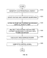
- FIG. 10 is a flow chart illustrating a method for monitoring power dosage according to embodiments of the present disclosure. This method may be implemented by using both digital and analog circuits. The method first compensates for the phase shift caused by a circuit network including an electrosurgical generator and a cable connected to deliver electrosurgical energy to treat tissue using analog circuitry, and then calculates the power delivered to and consumed by the tissue using digital circuitry.
- the electrosurgical generator generates electrosurgical energy in step 1010 that may be in a form of alternating voltage and current waveforms.
- sensors sense the voltage and current waveforms.
- analog all-pass filters APFs
- filter the voltage and current waveforms Since the generated voltage and current waveforms may have a phase shift and gain inaccuracy caused by the circuit network and the APFs also includes a phase delay and gain, the APFs may be designed in a way so that the phase delay of the APFs can compensate for the phase shift and the gains compensated. In this way, the output of the APFs has substantially a zero phase difference between the voltage and current waveforms and no inaccuracy in the gains.
- step 1040 the gain and phase-compensated voltage and current waveforms are multiplied to provide an analog power waveform. Due to the substantially zero phase difference, the analog power waveform is real and not complex. This analog power waveform is provided to the digital circuitry that computes real average power in step 1050. The controller of the electrosurgical generator then compares the computed real average power with a predetermined power profile that is specific for an electrosurgical operation and generates a control signal in step 1060. Steps 1010-1060 are continuously performed until a user of the electrosurgical generator terminates the operation or disconnects the cable from the electrosurgical generator.
Landscapes
- Health & Medical Sciences (AREA)
- Surgery (AREA)
- Engineering & Computer Science (AREA)
- Life Sciences & Earth Sciences (AREA)
- Biomedical Technology (AREA)
- Otolaryngology (AREA)
- Nuclear Medicine, Radiotherapy & Molecular Imaging (AREA)
- Plasma & Fusion (AREA)
- Physics & Mathematics (AREA)
- Heart & Thoracic Surgery (AREA)
- Medical Informatics (AREA)
- Molecular Biology (AREA)
- Animal Behavior & Ethology (AREA)
- General Health & Medical Sciences (AREA)
- Public Health (AREA)
- Veterinary Medicine (AREA)
- Surgical Instruments (AREA)
Applications Claiming Priority (2)
| Application Number | Priority Date | Filing Date | Title |
|---|---|---|---|
| US201361891817P | 2013-10-16 | 2013-10-16 | |
| US14/447,049 US9913679B2 (en) | 2013-10-16 | 2014-07-30 | Electrosurgical systems and methods for monitoring power dosage |
Publications (2)
| Publication Number | Publication Date |
|---|---|
| EP2868285A1 true EP2868285A1 (de) | 2015-05-06 |
| EP2868285B1 EP2868285B1 (de) | 2018-10-31 |
Family
ID=51627949
Family Applications (1)
| Application Number | Title | Priority Date | Filing Date |
|---|---|---|---|
| EP14185328.3A Not-in-force EP2868285B1 (de) | 2013-10-16 | 2014-09-18 | Elektrochirurgische Systeme zur Überwachung der Stromdosierung |
Country Status (2)
| Country | Link |
|---|---|
| US (1) | US9913679B2 (de) |
| EP (1) | EP2868285B1 (de) |
Cited By (3)
| Publication number | Priority date | Publication date | Assignee | Title |
|---|---|---|---|---|
| WO2020240280A3 (en) * | 2019-05-30 | 2021-02-18 | Stryker European Operations Limited | Electrosurgical generator |
| WO2023031472A3 (en) * | 2021-09-03 | 2023-04-13 | Analog Devices International Unlimited Company | An apparatus correcting the frequency response of a current measurement system |
| US11841386B2 (en) | 2018-06-13 | 2023-12-12 | Analog Devices International Unlimited Company | Apparatus for and method of correcting for a gain error resulting from the position of a pole or zero in a transfer function and to a current measurement device including such an apparatus |
Families Citing this family (3)
| Publication number | Priority date | Publication date | Assignee | Title |
|---|---|---|---|---|
| US11446078B2 (en) | 2015-07-20 | 2022-09-20 | Megadyne Medical Products, Inc. | Electrosurgical wave generator |
| RU2672376C2 (ru) * | 2017-02-13 | 2018-11-14 | Илья Николаевич Кустов | Система коррекции выходной мощности электрохирургического аппарата |
| US11054877B2 (en) * | 2017-08-07 | 2021-07-06 | Intel Corporation | Power management based on real time platform power sensing |
Citations (7)
| Publication number | Priority date | Publication date | Assignee | Title |
|---|---|---|---|---|
| WO1993008756A1 (en) * | 1991-11-08 | 1993-05-13 | Ep Technologies, Inc. | Radiofrequency ablation with phase sensitive power detection |
| JPH0759794A (ja) * | 1993-08-20 | 1995-03-07 | Ep Technol Inc | 位相敏感電力検出機能を備えたラジオ波切除装置 |
| JPH10504485A (ja) * | 1994-08-24 | 1998-05-06 | ベスタ・メデイカル・インコーポレーテツド | 凝結用鉗子 |
| JPH11197158A (ja) * | 1998-01-08 | 1999-07-27 | Olympus Optical Co Ltd | 焼灼止血装置 |
| US20050113819A1 (en) * | 2003-11-21 | 2005-05-26 | Wham Robert H. | Automatic control system for an electrosurgical generator |
| US20070129716A1 (en) * | 2000-12-28 | 2007-06-07 | Derek Daw | Electrosurgical medical system and method |
| EP2510895A1 (de) * | 2011-04-12 | 2012-10-17 | Tyco Healthcare Group LP | Systeme und Verfahren zur Kalibrierung von Leistungsmessungen in einem elektrochirurgischen Generator |
Family Cites Families (71)
| Publication number | Priority date | Publication date | Assignee | Title |
|---|---|---|---|---|
| DE179607C (de) | 1906-11-12 | |||
| DE390937C (de) | 1922-10-13 | 1924-03-03 | Adolf Erb | Vorrichtung zur Innenbeheizung von Wannenoefen zum Haerten, Anlassen, Gluehen, Vergueten und Schmelzen |
| DE1099658B (de) | 1959-04-29 | 1961-02-16 | Siemens Reiniger Werke Ag | Selbsttaetige Einschaltvorrichtung fuer Hochfrequenzchirurgiegeraete |
| FR1275415A (fr) | 1960-09-26 | 1961-11-10 | Dispositif détecteur de perturbations pour installations électriques, notamment d'électrochirurgie | |
| DE1139927B (de) | 1961-01-03 | 1962-11-22 | Friedrich Laber | Hochfrequenz-Chirurgiegeraet |
| DE1149832C2 (de) | 1961-02-25 | 1977-10-13 | Siemens AG, 1000 Berlin und 8000 München | Hochfrequenz-chirurgieapparat |
| FR1347865A (fr) | 1962-11-22 | 1964-01-04 | Perfectionnements aux appareils de diathermo-coagulation | |
| DE1439302B2 (de) | 1963-10-26 | 1971-05-19 | Siemens AG, 1000 Berlin u 8000 München | Hochfrequenz Chirurgiegerat |
| GB1480736A (en) | 1973-08-23 | 1977-07-20 | Matburn Ltd | Electrodiathermy apparatus |
| FR2251864A1 (en) | 1973-11-21 | 1975-06-13 | Termiflex Corp | Portable input and output unit for connection to a data processor - is basically a calculator with transmitter and receiver |
| DE2407559C3 (de) | 1974-02-16 | 1982-01-21 | Dornier System Gmbh, 7990 Friedrichshafen | Wärmesonde |
| US4237887A (en) | 1975-01-23 | 1980-12-09 | Valleylab, Inc. | Electrosurgical device |
| DE2504280C3 (de) | 1975-02-01 | 1980-08-28 | Hans Heinrich Prof. Dr. 8035 Gauting Meinke | Vorrichtung zum Schneiden und/oder Koagulieren menschlichen Gewebes mit Hochfrequenzstrom |
| CA1064581A (en) | 1975-06-02 | 1979-10-16 | Stephen W. Andrews | Pulse control circuit and method for electrosurgical units |
| DE2540968C2 (de) | 1975-09-13 | 1982-12-30 | Erbe Elektromedizin GmbH, 7400 Tübingen | Einrichtung zum Einschalten des Koagulationsstroms einer bipolaren Koagulationspinzette |
| US4094320A (en) | 1976-09-09 | 1978-06-13 | Valleylab, Inc. | Electrosurgical safety circuit and method of using same |
| FR2390968A1 (fr) | 1977-05-16 | 1978-12-15 | Skovajsa Joseph | Dispositif de traitement local d'un patient, notamment pour acupuncture ou auriculotherapie |
| SU727201A2 (ru) | 1977-11-02 | 1980-04-15 | Киевский Научно-Исследовательский Институт Нейрохирургии | Электрохирургический аппарат |
| DE2803275C3 (de) | 1978-01-26 | 1980-09-25 | Aesculap-Werke Ag Vormals Jetter & Scheerer, 7200 Tuttlingen | Fernschalteinrichtung zum Schalten eines monopolaren HF-Chirurgiegerätes |
| DE2823291A1 (de) | 1978-05-27 | 1979-11-29 | Rainer Ing Grad Koch | Schaltung zur automatischen einschaltung des hochfrequenzstromes von hochfrequenz-koagulationsgeraeten |
| DE2946728A1 (de) | 1979-11-20 | 1981-05-27 | Erbe Elektromedizin GmbH & Co KG, 7400 Tübingen | Hochfrequenz-chirurgiegeraet |
| JPS5778844A (en) | 1980-11-04 | 1982-05-17 | Kogyo Gijutsuin | Lasre knife |
| DE3045996A1 (de) | 1980-12-05 | 1982-07-08 | Medic Eschmann Handelsgesellschaft für medizinische Instrumente mbH, 2000 Hamburg | Elektro-chirurgiegeraet |
| FR2502935B1 (fr) | 1981-03-31 | 1985-10-04 | Dolley Roger | Procede et dispositif de controle de la coagulation de tissus a l'aide d'un courant a haute frequence |
| DE3120102A1 (de) | 1981-05-20 | 1982-12-09 | F.L. Fischer GmbH & Co, 7800 Freiburg | Anordnung zur hochfrequenzkoagulation von eiweiss fuer chirurgische zwecke |
| FR2517953A1 (fr) | 1981-12-10 | 1983-06-17 | Alvar Electronic | Appareil diaphanometre et son procede d'utilisation |
| FR2573301B3 (fr) | 1984-11-16 | 1987-04-30 | Lamidey Gilles | Pince chirurgicale et son appareillage de commande et de controle |
| DE3510586A1 (de) | 1985-03-23 | 1986-10-02 | Erbe Elektromedizin GmbH, 7400 Tübingen | Kontrolleinrichtung fuer ein hochfrequenz-chirurgiegeraet |
| DE3604823C2 (de) | 1986-02-15 | 1995-06-01 | Lindenmeier Heinz | Hochfrequenzgenerator mit automatischer Leistungsregelung für die Hochfrequenzchirurgie |
| EP0246350A1 (de) | 1986-05-23 | 1987-11-25 | Erbe Elektromedizin GmbH. | Koagulationselektrode |
| JPS635876A (ja) | 1986-06-27 | 1988-01-11 | Hitachi Seiko Ltd | ア−ク溶接機 |
| DE3638748A1 (de) | 1986-11-13 | 1988-06-01 | Hirschmann Radiotechnik | Kapazitives trennglied |
| US5073167A (en) | 1987-06-26 | 1991-12-17 | M/A-Com, Inc. | In-line microwave warming apparatus |
| US4931047A (en) | 1987-09-30 | 1990-06-05 | Cavitron, Inc. | Method and apparatus for providing enhanced tissue fragmentation and/or hemostasis |
| EP0325456B1 (de) | 1988-01-20 | 1995-12-27 | G2 Design Limited | Diathermiegerät |
| EP0336742A3 (de) | 1988-04-08 | 1990-05-16 | Bristol-Myers Company | Methode und Gerät zur Eichung eines elektrochirugischen Gerätes |
| DE3904558C2 (de) | 1989-02-15 | 1997-09-18 | Lindenmeier Heinz | Automatisch leistungsgeregelter Hochfrequenzgenerator für die Hochfrequenz-Chirurgie |
| EP0390937B1 (de) | 1989-04-01 | 1994-11-02 | Erbe Elektromedizin GmbH | Einrichtung zur Überwachung der Applikation von Neutralelektroden bei der Hochfrequenzchirurgie |
| DE3942998C2 (de) | 1989-12-27 | 1998-11-26 | Delma Elektro Med App | Elektrochirurgisches Hochfrequenzgerät |
| DE4205213A1 (de) | 1992-02-20 | 1993-08-26 | Delma Elektro Med App | Hochfrequenzchirurgiegeraet |
| DE4206433A1 (de) | 1992-02-29 | 1993-09-02 | Bosch Gmbh Robert | Kapazitives trennstueck |
| US5348554A (en) | 1992-12-01 | 1994-09-20 | Cardiac Pathways Corporation | Catheter for RF ablation with cooled electrode |
| US5336242A (en) * | 1993-05-26 | 1994-08-09 | Siemens Pacesetter, Inc. | Band-pass filter for use in a sense amplifier of an implantable cardiac pacer |
| DE4339049C2 (de) | 1993-11-16 | 2001-06-28 | Erbe Elektromedizin | Einrichtung zur Konfiguration chirurgischer Systeme |
| DE19506363A1 (de) | 1995-02-24 | 1996-08-29 | Frost Lore Geb Haupt | Verfahren zur nicht-invasiven Thermometrie in Organen unter medizinischen Hyperthermie- und Koagulationsbedingungen |
| US5837001A (en) | 1995-12-08 | 1998-11-17 | C. R. Bard | Radio frequency energy delivery system for multipolar electrode catheters |
| DE19643127A1 (de) | 1996-10-18 | 1998-04-23 | Berchtold Gmbh & Co Geb | Hochfrequenzchirurgiegerät und Verfahren zu dessen Betrieb |
| DE19717411A1 (de) | 1997-04-25 | 1998-11-05 | Aesculap Ag & Co Kg | Verfahren und Vorrichtung zur Überwachung der thermischen Belastung des Gewebes eines Patienten |
| US5838558A (en) | 1997-05-19 | 1998-11-17 | Trw Inc. | Phase staggered full-bridge converter with soft-PWM switching |
| DE59712260D1 (de) | 1997-06-06 | 2005-05-12 | Endress & Hauser Gmbh & Co Kg | Mit Mikrowellen arbeitendes Füllstandsmessgerät |
| DE19848540A1 (de) | 1998-10-21 | 2000-05-25 | Reinhard Kalfhaus | Schaltungsanordnung und Verfahren zum Betreiben eines Wechselrichters |
| US6203541B1 (en) | 1999-04-23 | 2001-03-20 | Sherwood Services Ag | Automatic activation of electrosurgical generator bipolar output |
| EP1307154B1 (de) | 2000-08-08 | 2005-02-23 | Erbe Elektromedizin GmbH | Hochfrequenzgenerator für die hochfrequenzchirurgie mit einstellbarer leistungsbegrenzung |
| JP4499893B2 (ja) | 2000-08-23 | 2010-07-07 | オリンパス株式会社 | 電気手術装置 |
| DE10061278B4 (de) | 2000-12-08 | 2004-09-16 | GFD-Gesellschaft für Diamantprodukte mbH | Instrument für chirurgische Zwecke |
| DE10218895B4 (de) | 2002-04-26 | 2006-12-21 | Storz Endoskop Produktions Gmbh | Hochfrequenz-Chirurgiegenerator |
| US7041096B2 (en) | 2002-10-24 | 2006-05-09 | Synergetics Usa, Inc. | Electrosurgical generator apparatus |
| US7722601B2 (en) | 2003-05-01 | 2010-05-25 | Covidien Ag | Method and system for programming and controlling an electrosurgical generator system |
| JP2005185657A (ja) | 2003-12-26 | 2005-07-14 | Olympus Corp | 外科用処置具 |
| DE102004025613B4 (de) | 2004-05-25 | 2008-08-07 | Erbe Elektromedizin Gmbh | Verfahren und Messvorrichtung zur Bestimmung der Übergangsimpendanz zwischen zwei Teilelektroden einer geteilten Neutralelektrode |
| DE102004054575A1 (de) | 2004-11-11 | 2006-05-24 | Erbe Elektromedizin Gmbh | Regelung für ein HF-Chirurgiegerät |
| US7602127B2 (en) | 2005-04-18 | 2009-10-13 | Mks Instruments, Inc. | Phase and frequency control of a radio frequency generator from an external source |
| US8734438B2 (en) | 2005-10-21 | 2014-05-27 | Covidien Ag | Circuit and method for reducing stored energy in an electrosurgical generator |
| CN101534733B (zh) | 2006-10-31 | 2011-12-07 | 奥林巴斯医疗株式会社 | 高频烧灼电源装置 |
| US7777567B2 (en) | 2007-01-25 | 2010-08-17 | Mks Instruments, Inc. | RF power amplifier stability network |
| USD574323S1 (en) | 2007-02-12 | 2008-08-05 | Tyco Healthcare Group Lp | Generator |
| DE102007056468A1 (de) | 2007-11-22 | 2009-06-04 | Hüttinger Elektronik Gmbh + Co. Kg | Messsignalverarbeitungseinrichtung und Verfahren zur Verarbeitung von zumindest zwei Messsignalen |
| DE102008058737B4 (de) | 2008-09-08 | 2019-12-12 | Erbe Elektromedizin Gmbh | HF-Chirurgiegenerator |
| US8685015B2 (en) | 2009-09-24 | 2014-04-01 | Covidien Lp | System and method for multi-pole phase-shifted radio frequency application |
| US8314561B2 (en) | 2010-04-02 | 2012-11-20 | Mks Instruments, Inc. | Multi-channel radio frequency generator |
| US8576013B2 (en) | 2011-12-29 | 2013-11-05 | Mks Instruments, Inc. | Power distortion-based servo control systems for frequency tuning RF power sources |
-
2014
- 2014-07-30 US US14/447,049 patent/US9913679B2/en active Active
- 2014-09-18 EP EP14185328.3A patent/EP2868285B1/de not_active Not-in-force
Patent Citations (7)
| Publication number | Priority date | Publication date | Assignee | Title |
|---|---|---|---|---|
| WO1993008756A1 (en) * | 1991-11-08 | 1993-05-13 | Ep Technologies, Inc. | Radiofrequency ablation with phase sensitive power detection |
| JPH0759794A (ja) * | 1993-08-20 | 1995-03-07 | Ep Technol Inc | 位相敏感電力検出機能を備えたラジオ波切除装置 |
| JPH10504485A (ja) * | 1994-08-24 | 1998-05-06 | ベスタ・メデイカル・インコーポレーテツド | 凝結用鉗子 |
| JPH11197158A (ja) * | 1998-01-08 | 1999-07-27 | Olympus Optical Co Ltd | 焼灼止血装置 |
| US20070129716A1 (en) * | 2000-12-28 | 2007-06-07 | Derek Daw | Electrosurgical medical system and method |
| US20050113819A1 (en) * | 2003-11-21 | 2005-05-26 | Wham Robert H. | Automatic control system for an electrosurgical generator |
| EP2510895A1 (de) * | 2011-04-12 | 2012-10-17 | Tyco Healthcare Group LP | Systeme und Verfahren zur Kalibrierung von Leistungsmessungen in einem elektrochirurgischen Generator |
Cited By (3)
| Publication number | Priority date | Publication date | Assignee | Title |
|---|---|---|---|---|
| US11841386B2 (en) | 2018-06-13 | 2023-12-12 | Analog Devices International Unlimited Company | Apparatus for and method of correcting for a gain error resulting from the position of a pole or zero in a transfer function and to a current measurement device including such an apparatus |
| WO2020240280A3 (en) * | 2019-05-30 | 2021-02-18 | Stryker European Operations Limited | Electrosurgical generator |
| WO2023031472A3 (en) * | 2021-09-03 | 2023-04-13 | Analog Devices International Unlimited Company | An apparatus correcting the frequency response of a current measurement system |
Also Published As
| Publication number | Publication date |
|---|---|
| US9913679B2 (en) | 2018-03-13 |
| US20150105768A1 (en) | 2015-04-16 |
| EP2868285B1 (de) | 2018-10-31 |
Similar Documents
| Publication | Publication Date | Title |
|---|---|---|
| EP2868285B1 (de) | Elektrochirurgische Systeme zur Überwachung der Stromdosierung | |
| JP6410505B2 (ja) | 電気外科用ケーブルを通して組織インピーダンスを測定するシステムおよび方法 | |
| US9498276B2 (en) | Systems and methods for narrowband real impedance control in electrosurgery | |
| US9918775B2 (en) | Systems and methods for calibrating power measurements in an electrosurgical generator | |
| EP2620114B1 (de) | Systeme für die phasenvorhersagbare Impedanzverlust-Modellkalibrierung und -ausgleich | |
| EP2898847B1 (de) | Systeme zur Multifrequenzkabelkompensation | |
| EP3100695B1 (de) | Steuerungssysteme für elektrochirurgischen generator | |
| US20230200881A1 (en) | Systems and methods for calculating tissue impedance in electrosurgery | |
| EP2832310B1 (de) | Systeme zur Messung der Gewebeimpedanz durch ein elektrochirurgisches Kabel |
Legal Events
| Date | Code | Title | Description |
|---|---|---|---|
| PUAI | Public reference made under article 153(3) epc to a published international application that has entered the european phase |
Free format text: ORIGINAL CODE: 0009012 |
|
| 17P | Request for examination filed |
Effective date: 20140918 |
|
| AK | Designated contracting states |
Kind code of ref document: A1 Designated state(s): AL AT BE BG CH CY CZ DE DK EE ES FI FR GB GR HR HU IE IS IT LI LT LU LV MC MK MT NL NO PL PT RO RS SE SI SK SM TR |
|
| AX | Request for extension of the european patent |
Extension state: BA ME |
|
| R17P | Request for examination filed (corrected) |
Effective date: 20150722 |
|
| RBV | Designated contracting states (corrected) |
Designated state(s): AL AT BE BG CH CY CZ DE DK EE ES FI FR GB GR HR HU IE IS IT LI LT LU LV MC MK MT NL NO PL PT RO RS SE SI SK SM TR |
|
| STAA | Information on the status of an ep patent application or granted ep patent |
Free format text: STATUS: EXAMINATION IS IN PROGRESS |
|
| 17Q | First examination report despatched |
Effective date: 20170926 |
|
| GRAP | Despatch of communication of intention to grant a patent |
Free format text: ORIGINAL CODE: EPIDOSNIGR1 |
|
| STAA | Information on the status of an ep patent application or granted ep patent |
Free format text: STATUS: GRANT OF PATENT IS INTENDED |
|
| RIC1 | Information provided on ipc code assigned before grant |
Ipc: A61B 18/12 20060101AFI20180329BHEP Ipc: A61B 18/00 20060101ALN20180329BHEP |
|
| RIC1 | Information provided on ipc code assigned before grant |
Ipc: A61B 18/12 20060101AFI20180411BHEP Ipc: A61B 18/00 20060101ALN20180411BHEP |
|
| INTG | Intention to grant announced |
Effective date: 20180430 |
|
| GRAS | Grant fee paid |
Free format text: ORIGINAL CODE: EPIDOSNIGR3 |
|
| GRAA | (expected) grant |
Free format text: ORIGINAL CODE: 0009210 |
|
| STAA | Information on the status of an ep patent application or granted ep patent |
Free format text: STATUS: THE PATENT HAS BEEN GRANTED |
|
| AK | Designated contracting states |
Kind code of ref document: B1 Designated state(s): AL AT BE BG CH CY CZ DE DK EE ES FI FR GB GR HR HU IE IS IT LI LT LU LV MC MK MT NL NO PL PT RO RS SE SI SK SM TR |
|
| REG | Reference to a national code |
Ref country code: CH Ref legal event code: EP Ref country code: GB Ref legal event code: FG4D |
|
| REG | Reference to a national code |
Ref country code: AT Ref legal event code: REF Ref document number: 1058458 Country of ref document: AT Kind code of ref document: T Effective date: 20181115 |
|
| REG | Reference to a national code |
Ref country code: DE Ref legal event code: R096 Ref document number: 602014035004 Country of ref document: DE |
|
| REG | Reference to a national code |
Ref country code: IE Ref legal event code: FG4D |
|
| REG | Reference to a national code |
Ref country code: NL Ref legal event code: MP Effective date: 20181031 |
|
| REG | Reference to a national code |
Ref country code: LT Ref legal event code: MG4D |
|
| REG | Reference to a national code |
Ref country code: AT Ref legal event code: MK05 Ref document number: 1058458 Country of ref document: AT Kind code of ref document: T Effective date: 20181031 |
|
| PG25 | Lapsed in a contracting state [announced via postgrant information from national office to epo] |
Ref country code: IS Free format text: LAPSE BECAUSE OF FAILURE TO SUBMIT A TRANSLATION OF THE DESCRIPTION OR TO PAY THE FEE WITHIN THE PRESCRIBED TIME-LIMIT Effective date: 20190228 Ref country code: LV Free format text: LAPSE BECAUSE OF FAILURE TO SUBMIT A TRANSLATION OF THE DESCRIPTION OR TO PAY THE FEE WITHIN THE PRESCRIBED TIME-LIMIT Effective date: 20181031 Ref country code: AT Free format text: LAPSE BECAUSE OF FAILURE TO SUBMIT A TRANSLATION OF THE DESCRIPTION OR TO PAY THE FEE WITHIN THE PRESCRIBED TIME-LIMIT Effective date: 20181031 Ref country code: HR Free format text: LAPSE BECAUSE OF FAILURE TO SUBMIT A TRANSLATION OF THE DESCRIPTION OR TO PAY THE FEE WITHIN THE PRESCRIBED TIME-LIMIT Effective date: 20181031 Ref country code: NO Free format text: LAPSE BECAUSE OF FAILURE TO SUBMIT A TRANSLATION OF THE DESCRIPTION OR TO PAY THE FEE WITHIN THE PRESCRIBED TIME-LIMIT Effective date: 20190131 Ref country code: PL Free format text: LAPSE BECAUSE OF FAILURE TO SUBMIT A TRANSLATION OF THE DESCRIPTION OR TO PAY THE FEE WITHIN THE PRESCRIBED TIME-LIMIT Effective date: 20181031 Ref country code: BG Free format text: LAPSE BECAUSE OF FAILURE TO SUBMIT A TRANSLATION OF THE DESCRIPTION OR TO PAY THE FEE WITHIN THE PRESCRIBED TIME-LIMIT Effective date: 20190131 Ref country code: ES Free format text: LAPSE BECAUSE OF FAILURE TO SUBMIT A TRANSLATION OF THE DESCRIPTION OR TO PAY THE FEE WITHIN THE PRESCRIBED TIME-LIMIT Effective date: 20181031 Ref country code: LT Free format text: LAPSE BECAUSE OF FAILURE TO SUBMIT A TRANSLATION OF THE DESCRIPTION OR TO PAY THE FEE WITHIN THE PRESCRIBED TIME-LIMIT Effective date: 20181031 Ref country code: FI Free format text: LAPSE BECAUSE OF FAILURE TO SUBMIT A TRANSLATION OF THE DESCRIPTION OR TO PAY THE FEE WITHIN THE PRESCRIBED TIME-LIMIT Effective date: 20181031 |
|
| PG25 | Lapsed in a contracting state [announced via postgrant information from national office to epo] |
Ref country code: RS Free format text: LAPSE BECAUSE OF FAILURE TO SUBMIT A TRANSLATION OF THE DESCRIPTION OR TO PAY THE FEE WITHIN THE PRESCRIBED TIME-LIMIT Effective date: 20181031 Ref country code: NL Free format text: LAPSE BECAUSE OF FAILURE TO SUBMIT A TRANSLATION OF THE DESCRIPTION OR TO PAY THE FEE WITHIN THE PRESCRIBED TIME-LIMIT Effective date: 20181031 Ref country code: GR Free format text: LAPSE BECAUSE OF FAILURE TO SUBMIT A TRANSLATION OF THE DESCRIPTION OR TO PAY THE FEE WITHIN THE PRESCRIBED TIME-LIMIT Effective date: 20190201 Ref country code: SE Free format text: LAPSE BECAUSE OF FAILURE TO SUBMIT A TRANSLATION OF THE DESCRIPTION OR TO PAY THE FEE WITHIN THE PRESCRIBED TIME-LIMIT Effective date: 20181031 Ref country code: PT Free format text: LAPSE BECAUSE OF FAILURE TO SUBMIT A TRANSLATION OF THE DESCRIPTION OR TO PAY THE FEE WITHIN THE PRESCRIBED TIME-LIMIT Effective date: 20190301 Ref country code: AL Free format text: LAPSE BECAUSE OF FAILURE TO SUBMIT A TRANSLATION OF THE DESCRIPTION OR TO PAY THE FEE WITHIN THE PRESCRIBED TIME-LIMIT Effective date: 20181031 |
|
| PG25 | Lapsed in a contracting state [announced via postgrant information from national office to epo] |
Ref country code: DK Free format text: LAPSE BECAUSE OF FAILURE TO SUBMIT A TRANSLATION OF THE DESCRIPTION OR TO PAY THE FEE WITHIN THE PRESCRIBED TIME-LIMIT Effective date: 20181031 Ref country code: IT Free format text: LAPSE BECAUSE OF FAILURE TO SUBMIT A TRANSLATION OF THE DESCRIPTION OR TO PAY THE FEE WITHIN THE PRESCRIBED TIME-LIMIT Effective date: 20181031 Ref country code: CZ Free format text: LAPSE BECAUSE OF FAILURE TO SUBMIT A TRANSLATION OF THE DESCRIPTION OR TO PAY THE FEE WITHIN THE PRESCRIBED TIME-LIMIT Effective date: 20181031 |
|
| REG | Reference to a national code |
Ref country code: DE Ref legal event code: R097 Ref document number: 602014035004 Country of ref document: DE |
|
| PG25 | Lapsed in a contracting state [announced via postgrant information from national office to epo] |
Ref country code: RO Free format text: LAPSE BECAUSE OF FAILURE TO SUBMIT A TRANSLATION OF THE DESCRIPTION OR TO PAY THE FEE WITHIN THE PRESCRIBED TIME-LIMIT Effective date: 20181031 Ref country code: SK Free format text: LAPSE BECAUSE OF FAILURE TO SUBMIT A TRANSLATION OF THE DESCRIPTION OR TO PAY THE FEE WITHIN THE PRESCRIBED TIME-LIMIT Effective date: 20181031 Ref country code: EE Free format text: LAPSE BECAUSE OF FAILURE TO SUBMIT A TRANSLATION OF THE DESCRIPTION OR TO PAY THE FEE WITHIN THE PRESCRIBED TIME-LIMIT Effective date: 20181031 Ref country code: SM Free format text: LAPSE BECAUSE OF FAILURE TO SUBMIT A TRANSLATION OF THE DESCRIPTION OR TO PAY THE FEE WITHIN THE PRESCRIBED TIME-LIMIT Effective date: 20181031 |
|
| PLBE | No opposition filed within time limit |
Free format text: ORIGINAL CODE: 0009261 |
|
| STAA | Information on the status of an ep patent application or granted ep patent |
Free format text: STATUS: NO OPPOSITION FILED WITHIN TIME LIMIT |
|
| 26N | No opposition filed |
Effective date: 20190801 |
|
| PG25 | Lapsed in a contracting state [announced via postgrant information from national office to epo] |
Ref country code: SI Free format text: LAPSE BECAUSE OF FAILURE TO SUBMIT A TRANSLATION OF THE DESCRIPTION OR TO PAY THE FEE WITHIN THE PRESCRIBED TIME-LIMIT Effective date: 20181031 |
|
| PG25 | Lapsed in a contracting state [announced via postgrant information from national office to epo] |
Ref country code: TR Free format text: LAPSE BECAUSE OF FAILURE TO SUBMIT A TRANSLATION OF THE DESCRIPTION OR TO PAY THE FEE WITHIN THE PRESCRIBED TIME-LIMIT Effective date: 20181031 |
|
| PG25 | Lapsed in a contracting state [announced via postgrant information from national office to epo] |
Ref country code: MC Free format text: LAPSE BECAUSE OF FAILURE TO SUBMIT A TRANSLATION OF THE DESCRIPTION OR TO PAY THE FEE WITHIN THE PRESCRIBED TIME-LIMIT Effective date: 20181031 |
|
| REG | Reference to a national code |
Ref country code: CH Ref legal event code: PL |
|
| PG25 | Lapsed in a contracting state [announced via postgrant information from national office to epo] |
Ref country code: LI Free format text: LAPSE BECAUSE OF NON-PAYMENT OF DUE FEES Effective date: 20190930 Ref country code: CH Free format text: LAPSE BECAUSE OF NON-PAYMENT OF DUE FEES Effective date: 20190930 Ref country code: LU Free format text: LAPSE BECAUSE OF NON-PAYMENT OF DUE FEES Effective date: 20190918 Ref country code: IE Free format text: LAPSE BECAUSE OF NON-PAYMENT OF DUE FEES Effective date: 20190918 |
|
| REG | Reference to a national code |
Ref country code: BE Ref legal event code: MM Effective date: 20190930 |
|
| PG25 | Lapsed in a contracting state [announced via postgrant information from national office to epo] |
Ref country code: BE Free format text: LAPSE BECAUSE OF NON-PAYMENT OF DUE FEES Effective date: 20190930 |
|
| GBPC | Gb: european patent ceased through non-payment of renewal fee |
Effective date: 20190918 |
|
| PG25 | Lapsed in a contracting state [announced via postgrant information from national office to epo] |
Ref country code: GB Free format text: LAPSE BECAUSE OF NON-PAYMENT OF DUE FEES Effective date: 20190918 |
|
| PG25 | Lapsed in a contracting state [announced via postgrant information from national office to epo] |
Ref country code: CY Free format text: LAPSE BECAUSE OF FAILURE TO SUBMIT A TRANSLATION OF THE DESCRIPTION OR TO PAY THE FEE WITHIN THE PRESCRIBED TIME-LIMIT Effective date: 20181031 |
|
| PG25 | Lapsed in a contracting state [announced via postgrant information from national office to epo] |
Ref country code: HU Free format text: LAPSE BECAUSE OF FAILURE TO SUBMIT A TRANSLATION OF THE DESCRIPTION OR TO PAY THE FEE WITHIN THE PRESCRIBED TIME-LIMIT; INVALID AB INITIO Effective date: 20140918 Ref country code: MT Free format text: LAPSE BECAUSE OF FAILURE TO SUBMIT A TRANSLATION OF THE DESCRIPTION OR TO PAY THE FEE WITHIN THE PRESCRIBED TIME-LIMIT Effective date: 20181031 |
|
| PGFP | Annual fee paid to national office [announced via postgrant information from national office to epo] |
Ref country code: FR Payment date: 20210819 Year of fee payment: 8 |
|
| PGFP | Annual fee paid to national office [announced via postgrant information from national office to epo] |
Ref country code: DE Payment date: 20210818 Year of fee payment: 8 |
|
| PG25 | Lapsed in a contracting state [announced via postgrant information from national office to epo] |
Ref country code: MK Free format text: LAPSE BECAUSE OF FAILURE TO SUBMIT A TRANSLATION OF THE DESCRIPTION OR TO PAY THE FEE WITHIN THE PRESCRIBED TIME-LIMIT Effective date: 20181031 |
|
| REG | Reference to a national code |
Ref country code: DE Ref legal event code: R119 Ref document number: 602014035004 Country of ref document: DE |
|
| PG25 | Lapsed in a contracting state [announced via postgrant information from national office to epo] |
Ref country code: FR Free format text: LAPSE BECAUSE OF NON-PAYMENT OF DUE FEES Effective date: 20220930 Ref country code: DE Free format text: LAPSE BECAUSE OF NON-PAYMENT OF DUE FEES Effective date: 20230401 |