EP2867390B1 - Method for producing tinplate and product produced therewith - Google Patents
Method for producing tinplate and product produced therewith Download PDFInfo
- Publication number
- EP2867390B1 EP2867390B1 EP13733301.9A EP13733301A EP2867390B1 EP 2867390 B1 EP2867390 B1 EP 2867390B1 EP 13733301 A EP13733301 A EP 13733301A EP 2867390 B1 EP2867390 B1 EP 2867390B1
- Authority
- EP
- European Patent Office
- Prior art keywords
- electrolyte
- tin
- anodic treatment
- treatment
- anodic
- Prior art date
- Legal status (The legal status is an assumption and is not a legal conclusion. Google has not performed a legal analysis and makes no representation as to the accuracy of the status listed.)
- Revoked
Links
Images
Classifications
-
- C—CHEMISTRY; METALLURGY
- C25—ELECTROLYTIC OR ELECTROPHORETIC PROCESSES; APPARATUS THEREFOR
- C25D—PROCESSES FOR THE ELECTROLYTIC OR ELECTROPHORETIC PRODUCTION OF COATINGS; ELECTROFORMING; APPARATUS THEREFOR
- C25D5/00—Electroplating characterised by the process; Pretreatment or after-treatment of workpieces
- C25D5/48—After-treatment of electroplated surfaces
-
- C—CHEMISTRY; METALLURGY
- C23—COATING METALLIC MATERIAL; COATING MATERIAL WITH METALLIC MATERIAL; CHEMICAL SURFACE TREATMENT; DIFFUSION TREATMENT OF METALLIC MATERIAL; COATING BY VACUUM EVAPORATION, BY SPUTTERING, BY ION IMPLANTATION OR BY CHEMICAL VAPOUR DEPOSITION, IN GENERAL; INHIBITING CORROSION OF METALLIC MATERIAL OR INCRUSTATION IN GENERAL
- C23C—COATING METALLIC MATERIAL; COATING MATERIAL WITH METALLIC MATERIAL; SURFACE TREATMENT OF METALLIC MATERIAL BY DIFFUSION INTO THE SURFACE, BY CHEMICAL CONVERSION OR SUBSTITUTION; COATING BY VACUUM EVAPORATION, BY SPUTTERING, BY ION IMPLANTATION OR BY CHEMICAL VAPOUR DEPOSITION, IN GENERAL
- C23C22/00—Chemical surface treatment of metallic material by reaction of the surface with a reactive liquid, leaving reaction products of surface material in the coating, e.g. conversion coatings, passivation of metals
- C23C22/73—Chemical surface treatment of metallic material by reaction of the surface with a reactive liquid, leaving reaction products of surface material in the coating, e.g. conversion coatings, passivation of metals characterised by the process
- C23C22/76—Applying the liquid by spraying
-
- C—CHEMISTRY; METALLURGY
- C25—ELECTROLYTIC OR ELECTROPHORETIC PROCESSES; APPARATUS THEREFOR
- C25D—PROCESSES FOR THE ELECTROLYTIC OR ELECTROPHORETIC PRODUCTION OF COATINGS; ELECTROFORMING; APPARATUS THEREFOR
- C25D11/00—Electrolytic coating by surface reaction, i.e. forming conversion layers
- C25D11/02—Anodisation
- C25D11/34—Anodisation of metals or alloys not provided for in groups C25D11/04 - C25D11/32
-
- C—CHEMISTRY; METALLURGY
- C25—ELECTROLYTIC OR ELECTROPHORETIC PROCESSES; APPARATUS THEREFOR
- C25D—PROCESSES FOR THE ELECTROLYTIC OR ELECTROPHORETIC PRODUCTION OF COATINGS; ELECTROFORMING; APPARATUS THEREFOR
- C25D3/00—Electroplating: Baths therefor
- C25D3/02—Electroplating: Baths therefor from solutions
- C25D3/30—Electroplating: Baths therefor from solutions of tin
Definitions
- the invention relates to a method for forming a passivation layer on an article having at least one tinplated surface having excellent sulphur staining resistance and to an article produced by said method.
- Tin is used to protect the steel base from corrosion both externally (aerobic conditions) and internally when in contact with foods (anaerobic). Under the anaerobic conditions expected inside an internally plain processed food can, tin will normally behave as the sacrificial anode, dissolving very slowly whilst protecting the steel base from corrosion and creating a reducing environment in the can. It is this mechanism that has enabled the plain tinplate can to maintain its long history and proven track record of providing wholesome food on a year round basis and safe storage for long periods of time.
- Some foods especially protein rich meat and fish and, to a lesser extent, vegetables (e.g. peas, beans, corn etc.) contain naturally occurring sulphur compounds. These can react with a plain tinplate surface to give a purple-black stain of tin sulphide. Although the stain is harmless, it may serve to change the passivation of the tinplate surface, which, in turn, could alter the rate of tin uptake. Whilst an overall increase in passivation is more likely to slow tin uptake, localised areas of staining can have a detrimental effect, especially if a corrosion accelerator such as oxygen is also present. Degree of sulphide staining is also influenced by pH, process time and temperature and the presence of certain cations.
- Passivation refers to the chemical treatment applied after tin deposition which stabilises the surface characteristics of tinplate by controlling tin oxide formation and growth.
- Passivation treatments can be electro-chemical or chemical. Electrochemical treatments involve the use of an external electric current. At present, cathodic dichromate (CDC) treatments are usually applied.
- CDC cathodic dichromate
- a CDC treatment is an electrochemical passivation treatment. Chromates are based on hexavalent chromium and these are nowadays considered to be hazardous substances being potentially harmful to the environment and a risk in terms of worker safety. Consequently, intensive research efforts are being made towards developing passivation treatments free from hexavalent chromium, also denoted as Cr(VI)-free passivation treatments.
- the most common method to improve the sulphide staining resistance of Cr(VI)-free passivated tinplate is to increase the thickness of the passivation layer itself (e.g. by using process conditions leading to thicker applied wet films, or by using more concentrated treatment solutions, or by employing longer treatment time, etc.) This leads to enhanced barrier properties, thus suppressing the formation of sulphide stains.
- passivation layers are mechanically weak and the risk of cohesive failure within the passivation layer increases with thickness. Cohesive failure of the passivation layer (in particular during heavy deformation that is encountered in e.g. canmaking) leads to loss of adhesion and delamination of organic coatings that are applied over the passivation layer.
- WO2012097926 discloses a method for electrolytically passivating tinplate by anodic polarisation in an alkalic aqueous electrolyte comprising a watersoluble silicate of composition M 2 O.nSiO 2 , wherein M is an alkalimetal-ion or a quaternary Ammonium-ion and n is a natural number between 0.8 and 7.
- US3616307 discloses a method of anodizing a tin-coated ferrous article by subjecting the article as anode to alectrolysis in an aqueous electrolyte comprising a solution of phospate in which the phosphate radical is present in an amount between 2 and 90 g/l and a hypophosphite in which the hypophosphite radical is present in an amount between 0.5 and 50 g/l at a current density of 8 to 100 asf (86 to 1076 A/m 2 ).
- the layer of tin oxide has to be further coated with a thin film of releasing agent and baked at 450 °F (232 °C) for 2 hours to cure the releasing agent and to stabilise the oxide film.
- US 2010/181201 discloses an electrolyte for passifying tin plated steel consisting of a mixture of organic hydroxyl acids and phenol organic acids
- the object of the invention is to provide a method to improve the sulphide staining resistance of tinplate that has been passivated using Cr(VI)-free passivation systems.
- Another object of the invention is to provide a method to improve the sulphide staining resistance of tinplate that has been passivated using Cr(VI)-free passivation systems that can be integrated into existing electrolitic tinning lines.
- Still another object of the invention is to provide a tinplated article having excellent sulphide staining resistance that is at least similar to that of a cathodic dichromate passivation treatment.
- the invention solves the problem of poor sulphide staining resistance of tinplate by subjecting the tinplate to an anodic treatment in a suitable aqueous electrolyte which is carried out within certain boundaries of treatment time, current density and total charge passed, in order to be effective in achieving the required sulphur staining resistance.
- a very thin layer of tin oxide on the tinplate surface is formed by the electrochemical anodic treatment. This tin oxide layer provides the improvement in sulphide staining resistance and together with the subsequent chemical Cr(VI)-free passivation treatment provides a tinplate which delivers the same, or a better performance than the known CDC-treated tinplate.
- An essential element of the invention is the thickness of the tin oxide layer (D), which is expressed in Coulomb/m 2 and represents the total charge needed to reduce the layer to metallic tin.
- the efficiency thus represents the ratio of the thickness D of the produced oxide layer to the applied charge density (A x t), and can be estimated by plotting D as a function of (A x t).
- the tin oxide layer thickness is determined using a coulometric method.
- the tin oxide layer is reduced by a controlled small cathodic current in a 0.1% solution of hydrobromic acid (HBr) that is freed from oxygen by scrubbing with nitrogen.
- the progress of the reduction of the oxide is monitored by measuring the reduction potential, and the charge passed (A*t) for the complete reduction serves as a measure of the tin oxide layer thickness.
- a cylindrical electrolysis cell is used having a circular aperture of ca. 4 cm diameter on one end. The other end of the cell contains a platinum counter electrode and an Ag/AgCl reference electrode.
- the test specimen covers the aperture, which is sealed using an O-ring to make a water-tight connection of well defined area (13.69 cm 2 in this case), and is tightened into place using an air-pressure cylinder.
- the cell is connected to the electrolyte solution by a flexible tube so that it can be filled and emptied under nitrogen atmosphere.
- a cathodic current density of -0.40 A/m 2 is applied to the sample using a potentiostat-galvanostat, and the potential is measured until the reduction is complete.
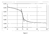
- a typical potential-time curve is shown in Fig. 1 , from which the tin oxide layer thickness is determined based on the inflection point of the potential drop at time t i .
- the sole purpose of the electrolyte is to enable the anodic treatment, not to deposit foreign species contained in the electrolyte onto the substrate surface.
- the pH is not lower than 8.5.
- a suitable maximum pH value is 11 or even 10.5.
- the electrolyte comprises monoatomic cations from Group 1 or 2 from the periodic table or polyatomic cations, and poly-atomic anions.
- Group 1 and Group 2 elements, according to the new IUPAC numbering comprise the alkali metals and the alkali earth metals. It is important that the electrolyte does not contain mono-atomic halogen anions (Group 17) such as Cl - , F - because these anions prevent the tin-oxide layer from forming.
- the article is optionally rinsed and dried before it is passed on to the subsequent step, i.e. the Cr(VI)-free passivation treatment.
- the need to rinse the anodically treated tinplate depends on the exact nature of the Cr(VI)-free passivation system, certain systems will be more susceptible than others to contamination of electrolyte being present on the tinplate surface.
- the Cr(VI)-free passivation system is applied to the anodically treated tinplate surface by application techniques that are common for such passivation systems. Suitable application techniques include: dipping, dipping with squeegee rolls, rotor-spray application, rotor-spray application supported by the use of a smoothing roll, spray application, spray-squeegee application, application by means of a roll coater systems, application by slot coating, slot curtain coating, etc.
- the strip is dried and passed on for final processing steps such as oiling, winding, cutting, etc.
- the total D as specified above can be achieved by any combination of A and t, but a combination of a high current density (A > 0.1 A/dm 2 , preferably A > 1.0 A/ dm 2 ) in combination with a short treatment time (t ⁇ 1 s) is preferred in view of its processability on a high-speed tinning line.
- a and t in the anodic treatment which is further demonstrated in Example 1 and Figures 2 and 3 , implies that the process can be operated at short treatment times, by adjusting the applied current density accordingly.
- the method according to the invention can be employed in industrial tinning lines running at line speeds in excess of 300 m/min to speeds of up to 1000 m/min.
- the anodic treatment is performed in-line with or immediately after electrolytic tinning, and wherein the anodic treatment time (t) is at most 5 seconds, preferably at most 2 seconds, more preferably between 0.05 seconds and 1.5 seconds. This range and the more preferable ranges are consistent with high speeds processing lines.
- the anodic treatment is performed in-line with an industrial electrolytic tinning line, and wherein the current density during the anodic treatment (A) is at least 10 A/m 2 , preferably at least 50 A/m 2 and more preferably at least 100 A/m 2 , and/or at most 4000 A/m 2 , preferably at most 2000 A/m 2 or more preferably at most 1000 A/m 2 . This range and the more preferable ranges are consistent with high speeds processing lines.
- the electrolyte to be employed can be an aqueous solution of an acid, a base or a salt.
- the main function of the electrolyte is to support the electrochemical reaction intended by the anodic treatment while the ionic species present in the electrolyte do not take part in the electrochemical modification of the tinplate surface.
- the preferred electrolyte contains cations from Group 1 (e.g. Na + , K + ) or Group 2 (e.g. Mg 2+ , Ca 2+ ) from the Periodic Table or polyatomic cations (e.g. NH 4 + ), and polyatomic anions (phosphates, borates, sulphates, carbonates and the like).
- the anion may be the conjugate base of an organic acid (e.g. acetates, citrates). Since it is of importance that the pH be maintained within certain boundaries, a buffered solution could be used.
- the electrolyte may contain other chemical additives, such as surfactants, wetting agents, anti-foaming agents etc. to support the electrochemical treatment, provided these additives do not adversely affect the formation of the tin oxide.
- the anodic treatment of the tin-plated surface converts the extreme outer layer of the tin surface from metallic tin into tin oxide by electrochemical oxidation.
- the tin oxide layer produced as such provides a barrier against sulphide staining.
- the tin oxide layer is, however, not sufficiently stable and/or passive in itself and will, during prolonged storage under ambient and/or humid conditions, or during heat treatments such as baking and stoving, continue to grow into a thicker tin oxide layer with undesirable properties (poor wettability, yellowish appearance, poor lacquer adhesion).
- the Cr(VI)-free passivation system If we consider the Cr(VI)-free passivation system on its own, it usually will provide a stable passivation layer protecting the tinplate against uncontrolled growth of tin oxides and furthermore providing good adhesion of organic coatings. However, the Cr(VI)-free passivation layer in almost all investigated cases has a poor resistance against sulphide staining.
- a tin oxide layer of the correct thickness is applied by employing the anodic treatment under proper process conditions, and then the tin oxide layer is passivated and/or stabilised against further uncontrolled growth, by applying a Cr(VI)-free passivation system on top of it, by using a non-electrolytic application method.
- the anodic treatment of the present invention must take place after tinning and/or flow melting and before the application of a Cr(VI)-free passivation system.
- the Cr(VI)-free passivation system before which the anodic treatment is applied must be a chemical passivation treatment, preferably a so-called no-rinse process, for the application of a no-rinse, dry-in-place passivation system.
- the anodic pre-treatment is not expected to work in combination with a Cr(VI)-free passivation system that itself is applied electrolytically.
- the anodic pre-treatment is not expected to work in combination with a Cr(VI)-free passivation system that is applied by a cathodic electrochemical process, since such a process will remove the anodic treatment layer through electrochemical reduction.
- Suitable no-rinse Cr(VI)-free passivation systems that can be used in combination with the anodic treatment of this invention are e.g.:
- the anodic treatment of the present invention is capable of applying the suitable tin oxide layer on a very short time scale (down to 0.1 s), using environmentally friendly chemical solutions, and with a very low energy consumption.
- the method according to the invention also works with a thickness of the tin oxide layer of e.g. 150 or 200 C/m 2 it is preferable for the thickness of the tin oxide layer D to be at most 100 C/m 2 .
- a value above 100 is not possible to achieve economically in the high speed tinplating process and it also leads to a reduced adhesion of subsequently applied organic coatings.
- the preferred range for the tin oxide layer thickness D is therefore 30 to 100 C/m 2 .
- a suitable minimum value of D is 40 C/m 2 .
- a suitable maximum value for D from a process efficiency point of view is 80 C/m 2 or even 60 C/m 2 .
- the polyatomic anion in the electrolyte is a phosphate, a borate, a sulphate, or a carbonate anion.
- the cation in the electrolyte is Na + , K + (Group 1) and/or Ca 2+ (Group 2) and/or polyatomic e.g. NH4 + .
- the article is a strip of packaging steel provided with a tin layer on at least one side (for typical chemical compositions see e.g. EN10202-2001 or ASTM 623M).
- This strip is produced in a known way, e.g. by cold rolling and annealing and optionally temper rolling a steel strip of suitable composition, followed by electrolytic tinplating.
- the article is further provided with an organic coating layer such as epoxy-phenolic gold lacquers, epoxy-anhydride white lacquers, PVC or vinyl organosol coatings, polyester lacquers, epoxy-amino or epoxy-acrylic-amino waterborne coatings.
- an organic coating layer such as epoxy-phenolic gold lacquers, epoxy-anhydride white lacquers, PVC or vinyl organosol coatings, polyester lacquers, epoxy-amino or epoxy-acrylic-amino waterborne coatings.
- This Example describes various lab-scale trials that are aimed to demonstrate the anodic treatment using various electrolytes and process conditions regarding current density A and treatment time t.
- non-passivated tinplate was used.
- the material was produced on an industrial electrolytic tinning line (ETL).
- ETL electrolytic tinning line
- the applied tin coating weight is about 2.8 g/m 2 .
- the amount of free tin is about 1.9 g/m 2 and the amount of FeSn 2 alloy is about 1.1 g/m 2 , corresponding to about 0.9 g/m 2 of tin in the alloy layer.
- the tinplate strip was passed on the coiler while by-passing the chromate passivation section. In this way, non-passivated tinplate without contamination with chromium-residues is obtained.
- the tinplate sample was placed in the electrolyte at 50°C, and connected as the anode to a galvanostat.
- Various current densities in the range 0.2 - 1.4 A/dm 2
- treatment times in the range 0.4 - 9.0 s
- the sample was removed from the electrolyte, rinsed with deionised water and dried at ambient temperature. The tin oxide layer thickness was then determined as described above.
- Figure 1 gives a typical curve of reduction potential (V) as a function of time (t) in a tin oxide reduction experiment.
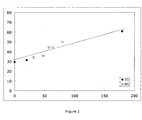
- Figure 2 gives the tin oxide layer thickness (in C/m 2 ) as a function of the charge passed (A*t) in the anodic treatment using the phosphate solution for different current densities (see legend) and time combinations.
- the dashed line serves as a guide to the eye.
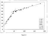
- Figure 3 gives the tin oxide layer thickness (in C/m 2 ) as a function of the charge passed (A*t) in the anodic treatment using the sodium carbonate solution for different current densities and time combinations. For instance, a current density of 120 A/m 2 for 0.4 seconds resulted in the same layer thickness as a current density of 60 A/m 2 for 0.8 seconds.
- the dashed lines serve as guide to the eye. From the different current densities (see legend) and the associated differences in treatment time it is clearly visible that the different combinations of time (t) and current density (A) result in the same tin layer thickness.
- the amount of tin oxide produced in the anodic treatment is a unique function of the charge passed. For a given charge, it does not matter whether this was achieved by e.g. a low current density and a long treatment time or by a high current density and a correspondingly short treatment time. Thus, the process of tin oxidation can be very easily controlled over the total charge passed and, in an industrial process can be made independent of e.g. line speed.
- a Cr(VI)-free passivation treatment was applied to the tinplate using a spray-and-squeegee application unit.
- the passivation solution was a commercial product, denoted GranodineTM 1456, from Henkel AG & Co. KGaA (Düsseldorf, Germany) containing, among other things, fluoro-titanates, fluoro-zirconates and organic polymers.
- a passivation solution containing 150 g/l of GranodineTM 1456 in deionised water was used in the experiments.
- the passivation solution was sprayed onto one side of the strip using an Ahlbrandt IQ-140 Rotorspray system.
- the strip was then passed through a (non-driven) pair of rollers consisting of a stainless steel coater roll and a polyurethane-coated backing roll, in which the applied wet film is homogenised and the excess liquid is squeezed off from the strip.
- a (non-driven) pair of rollers consisting of a stainless steel coater roll and a polyurethane-coated backing roll, in which the applied wet film is homogenised and the excess liquid is squeezed off from the strip.
- the strip is heated to 70°C using an inductive heater and subsequently passed through an air dryer operated at 90°C air temperature.
- the as-received, non-passivated tinplate coils were first passed through the line and were given a cathodic treatment in sodium carbonate using the electrochemical treatment tank. This is done to remove the 'natural' tin oxide layer that has developed on the non-passivated tinplate material during storage. A total cathodic current density of 1.11 A/dm 2 was employed during 0.72 s, giving a total charge density of 80 C/m 2 . Then, the treated coil was placed back on the uncoiler and subjected to the following treatments:
- the amount of tin oxide present on the treated surface was measured directly after preparing the samples, using the coulometric method described above. Then, the samples were stored at ambient temperature in dry air during 14 weeks, after which the tin oxide layer thickness was determined again. If the increase in tin oxide layer thickness during this period is 10 C/m 2 or less, the stability of the tin oxide layer is considered to be adequate.
- Our test method to determine sulphide staining resistance is based on measuring the dissolution rate of tin oxide during exposure to a sulphide solution. It is found that the rate of dissolution of tin oxides correlated strongly with the development of sulphide staining in real-life testing.
- the advantage of our method is that the results can be easily quantified, and offers a better and faster way to investigate sulphide staining as compared to the more commonly used visual observation.
- a particularly convenient method employs a solution containing 5 g/l NaOH and 5 g/l Na 2 S*3H 2 O maintained at 30°C.
- the samples were lacquered with a white-coloured, epoxy-anhydride internal food can lacquer.
- This lacquer is critical regarding adhesion and very discriminating in sterilisation tests and is commonly used in stringent product evaluation.
- the lacquer was applied at 10 - 12 g/m 2 dry coating weight.
- the lacquered panels were sterilised at 121°C during 60 minutes, in the following media:
- Comp.Ex. 1 shows that no treatment at all of the tinplate surface leads to poor tin oxide stability, poor sulphide staining resistance and poor lacquer adhesion.
- Comp.Ex. 2 shows that a Cr(VI)-free passivation treatment stabilises the tin oxide surface, provides excellent lacquer adhesion, but has a poor resistance to sulphide staining.
- Comp.Ex. 3 shows that the anodic treatment of the present invention provides much improved sulphide staining resistance, but since it is applied without further passivation treatment, the tin oxide layer is not stable and lacquer adhesion is poor.
- Inventive Examples 1 - 3 show that the combination of anodic treatment in combination with a Cr(VI)-free passivation treatment leads to the desired combination of improved sulphide staining resistance, a stable tin oxide layer and good lacquer adhesion.
Description
- The invention relates to a method for forming a passivation layer on an article having at least one tinplated surface having excellent sulphur staining resistance and to an article produced by said method.
- Tin is used to protect the steel base from corrosion both externally (aerobic conditions) and internally when in contact with foods (anaerobic). Under the anaerobic conditions expected inside an internally plain processed food can, tin will normally behave as the sacrificial anode, dissolving very slowly whilst protecting the steel base from corrosion and creating a reducing environment in the can. It is this mechanism that has enabled the plain tinplate can to maintain its long history and proven track record of providing wholesome food on a year round basis and safe storage for long periods of time.
- Some foods, especially protein rich meat and fish and, to a lesser extent, vegetables (e.g. peas, beans, corn etc.) contain naturally occurring sulphur compounds. These can react with a plain tinplate surface to give a purple-black stain of tin sulphide. Although the stain is harmless, it may serve to change the passivation of the tinplate surface, which, in turn, could alter the rate of tin uptake. Whilst an overall increase in passivation is more likely to slow tin uptake, localised areas of staining can have a detrimental effect, especially if a corrosion accelerator such as oxygen is also present. Degree of sulphide staining is also influenced by pH, process time and temperature and the presence of certain cations.
- Passivation refers to the chemical treatment applied after tin deposition which stabilises the surface characteristics of tinplate by controlling tin oxide formation and growth. Passivation treatments can be electro-chemical or chemical. Electrochemical treatments involve the use of an external electric current. At present, cathodic dichromate (CDC) treatments are usually applied. A CDC treatment is an electrochemical passivation treatment. Chromates are based on hexavalent chromium and these are nowadays considered to be hazardous substances being potentially harmful to the environment and a risk in terms of worker safety. Consequently, intensive research efforts are being made towards developing passivation treatments free from hexavalent chromium, also denoted as Cr(VI)-free passivation treatments.
- Recent developments of Cr(VI)-free passivation treatments have resulted in renewed attention to combatting sulphide staining because these newly developed alternatives to cathodic dichromate treatments struggle to deliver the same performance in terms of sulphide staining resistance.
- The most common method to improve the sulphide staining resistance of Cr(VI)-free passivated tinplate is to increase the thickness of the passivation layer itself (e.g. by using process conditions leading to thicker applied wet films, or by using more concentrated treatment solutions, or by employing longer treatment time, etc.) This leads to enhanced barrier properties, thus suppressing the formation of sulphide stains. However, passivation layers are mechanically weak and the risk of cohesive failure within the passivation layer increases with thickness. Cohesive failure of the passivation layer (in particular during heavy deformation that is encountered in e.g. canmaking) leads to loss of adhesion and delamination of organic coatings that are applied over the passivation layer.
-
WO2012097926 discloses a method for electrolytically passivating tinplate by anodic polarisation in an alkalic aqueous electrolyte comprising a watersoluble silicate of composition M2O.nSiO2, wherein M is an alkalimetal-ion or a quaternary Ammonium-ion and n is a natural number between 0.8 and 7. -
US3616307 discloses a method of anodizing a tin-coated ferrous article by subjecting the article as anode to alectrolysis in an aqueous electrolyte comprising a solution of phospate in which the phosphate radical is present in an amount between 2 and 90 g/l and a hypophosphite in which the hypophosphite radical is present in an amount between 0.5 and 50 g/l at a current density of 8 to 100 asf (86 to 1076 A/m2). The layer of tin oxide has to be further coated with a thin film of releasing agent and baked at 450 °F (232 °C) for 2 hours to cure the releasing agent and to stabilise the oxide film. -
US 2010/181201 discloses an electrolyte for passifying tin plated steel consisting of a mixture of organic hydroxyl acids and phenol organic acids The object of the invention is to provide a method to improve the sulphide staining resistance of tinplate that has been passivated using Cr(VI)-free passivation systems. - Another object of the invention is to provide a method to improve the sulphide staining resistance of tinplate that has been passivated using Cr(VI)-free passivation systems that can be integrated into existing electrolitic tinning lines.
- Still another object of the invention is to provide a tinplated article having excellent sulphide staining resistance that is at least similar to that of a cathodic dichromate passivation treatment.
- One or more of the objects of the invention are reached by a method according to claim 1. Preferred embodiments are provided in the dependent claims.
- The invention solves the problem of poor sulphide staining resistance of tinplate by subjecting the tinplate to an anodic treatment in a suitable aqueous electrolyte which is carried out within certain boundaries of treatment time, current density and total charge passed, in order to be effective in achieving the required sulphur staining resistance. A very thin layer of tin oxide on the tinplate surface is formed by the electrochemical anodic treatment. This tin oxide layer provides the improvement in sulphide staining resistance and together with the subsequent chemical Cr(VI)-free passivation treatment provides a tinplate which delivers the same, or a better performance than the known CDC-treated tinplate.
- An essential element of the invention is the thickness of the tin oxide layer (D), which is expressed in Coulomb/m2 and represents the total charge needed to reduce the layer to metallic tin. The thickness of the tin oxide layer is related to the anodic treatment time (t) and current density (A) by D = E x A x t, where E is the efficiency of the electrochemical reaction, and wherein D is at least 30 C/m2. The efficiency thus represents the ratio of the thickness D of the produced oxide layer to the applied charge density (A x t), and can be estimated by plotting D as a function of (A x t). Initially, at values of anodic charge passed below 50 C/m2 the curve is more or less linear, but with increasing anodic charge passed, the efficiency E decreases leading to a slower growth rate of the tin oxide layer, and thus in a slower increase in D. If D < 30 C/m2, then the tin oxide layer is too thin and is not effective in achieving the desired sulphide staining resistance. A minimum thickness of 30 C/m2 is therefore required.
- The tin oxide layer thickness is determined using a coulometric method. The tin oxide layer is reduced by a controlled small cathodic current in a 0.1% solution of hydrobromic acid (HBr) that is freed from oxygen by scrubbing with nitrogen. The progress of the reduction of the oxide is monitored by measuring the reduction potential, and the charge passed (A*t) for the complete reduction serves as a measure of the tin oxide layer thickness. For the test, a cylindrical electrolysis cell is used having a circular aperture of ca. 4 cm diameter on one end. The other end of the cell contains a platinum counter electrode and an Ag/AgCl reference electrode. The test specimen covers the aperture, which is sealed using an O-ring to make a water-tight connection of well defined area (13.69 cm2 in this case), and is tightened into place using an air-pressure cylinder. The cell is connected to the electrolyte solution by a flexible tube so that it can be filled and emptied under nitrogen atmosphere. A cathodic current density of -0.40 A/m2 is applied to the sample using a potentiostat-galvanostat, and the potential is measured until the reduction is complete. A typical potential-time curve is shown in
Fig. 1 , from which the tin oxide layer thickness is determined based on the inflection point of the potential drop at time ti. The tin oxide layer thickness D, expressed in C/m2, is obtained from D [C/m2] = ti [s] * 0.4 [A/m2]. - The sole purpose of the electrolyte is to enable the anodic treatment, not to deposit foreign species contained in the electrolyte onto the substrate surface. The pH of the electrolyte may not be too low, not lower than pH = 8, otherwise the efficiency of the electrochemical reaction becomes too low and then the process cannot be incorporated into existing high productivity process lines. Also, the pH of the electrolyte may not be too high, i.e. not higher than pH = 11.5 because that will cause the dissolution of the tin layer in the electrolyte. Preferably the pH is not lower than 8.5. A suitable maximum pH value is 11 or even 10.5.
- According to the invention the electrolyte comprises monoatomic cations from Group 1 or 2 from the periodic table or polyatomic cations, and poly-atomic anions. Group 1 and Group 2 elements, according to the new IUPAC numbering comprise the alkali metals and the alkali earth metals. It is important that the electrolyte does not contain mono-atomic halogen anions (Group 17) such as Cl-, F- because these anions prevent the tin-oxide layer from forming.
- After the anodic treatment the article is optionally rinsed and dried before it is passed on to the subsequent step, i.e. the Cr(VI)-free passivation treatment. The need to rinse the anodically treated tinplate depends on the exact nature of the Cr(VI)-free passivation system, certain systems will be more susceptible than others to contamination of electrolyte being present on the tinplate surface.
- Finally, the Cr(VI)-free passivation system is applied to the anodically treated tinplate surface by application techniques that are common for such passivation systems. Suitable application techniques include: dipping, dipping with squeegee rolls, rotor-spray application, rotor-spray application supported by the use of a smoothing roll, spray application, spray-squeegee application, application by means of a roll coater systems, application by slot coating, slot curtain coating, etc. After the passivation step, the strip is dried and passed on for final processing steps such as oiling, winding, cutting, etc.
- The total D as specified above can be achieved by any combination of A and t, but a combination of a high current density (A > 0.1 A/dm2, preferably A > 1.0 A/ dm2) in combination with a short treatment time (t < 1 s) is preferred in view of its processability on a high-speed tinning line. The interchangeability of A and t in the anodic treatment, which is further demonstrated in Example 1 and
Figures 2 and3 , implies that the process can be operated at short treatment times, by adjusting the applied current density accordingly. Thus, the method according to the invention can be employed in industrial tinning lines running at line speeds in excess of 300 m/min to speeds of up to 1000 m/min. Furthermore, the treatment time t is determined not only by line speed v but also by the effective length or 'anode length' L of the treatment section, according to t = L / v, meaning that the processing window can be further extended by the proper choice of the anode length L. For instance, to deposit a layer having a thickness of 50 C/m2 (assuming E=1) on a line running at 600 m/min (10 m/s) a current density A of 1000 A/m2 and a treatment length of 0.5 m would be required. It could also be done at a current density of 100 A/m2 if the treatment length is 5 m. This design and process flexibility is a great advantage of this method. - In an embodiment of the invention the anodic treatment is performed in-line with or immediately after electrolytic tinning, and wherein the anodic treatment time (t) is at most 5 seconds, preferably at most 2 seconds, more preferably between 0.05 seconds and 1.5 seconds. This range and the more preferable ranges are consistent with high speeds processing lines. In an embodiment the anodic treatment is performed in-line with an industrial electrolytic tinning line, and wherein the current density during the anodic treatment (A) is at least 10 A/m2, preferably at least 50 A/m2 and more preferably at least 100 A/m2, and/or at most 4000 A/m2, preferably at most 2000 A/m2 or more preferably at most 1000 A/m2. This range and the more preferable ranges are consistent with high speeds processing lines.
- The electrolyte to be employed can be an aqueous solution of an acid, a base or a salt. The main function of the electrolyte is to support the electrochemical reaction intended by the anodic treatment while the ionic species present in the electrolyte do not take part in the electrochemical modification of the tinplate surface. Although there is considerable freedom in selecting a suitable electrolyte, use the following ionic species must be avoided:
- monoatomic anions such as fluorides, chlorides, bromides, etc. since these are detrimental to forming a suitable tin oxide layer
- cations from or containing inner-transition metals, transition metals and post-transition metals; such elements typically exhibit multiple valency states and therefore can easily take part in electrochemical reactions, and may negatively affect the stability of the electrolyte by forming insoluble salts with the available anions, or by forming insoluble oxides
- Based on the above considerations, the preferred electrolyte contains cations from Group 1 (e.g. Na+, K+) or Group 2 (e.g. Mg2+, Ca2+) from the Periodic Table or polyatomic cations (e.g. NH4 +), and polyatomic anions (phosphates, borates, sulphates, carbonates and the like). Also, the anion may be the conjugate base of an organic acid (e.g. acetates, citrates). Since it is of importance that the pH be maintained within certain boundaries, a buffered solution could be used. Furthermore the electrolyte may contain other chemical additives, such as surfactants, wetting agents, anti-foaming agents etc. to support the electrochemical treatment, provided these additives do not adversely affect the formation of the tin oxide.
- The anodic treatment of the tin-plated surface converts the extreme outer layer of the tin surface from metallic tin into tin oxide by electrochemical oxidation. The tin oxide layer produced as such (within a certain range of thickness) provides a barrier against sulphide staining. The tin oxide layer is, however, not sufficiently stable and/or passive in itself and will, during prolonged storage under ambient and/or humid conditions, or during heat treatments such as baking and stoving, continue to grow into a thicker tin oxide layer with undesirable properties (poor wettability, yellowish appearance, poor lacquer adhesion).
- If we consider the Cr(VI)-free passivation system on its own, it usually will provide a stable passivation layer protecting the tinplate against uncontrolled growth of tin oxides and furthermore providing good adhesion of organic coatings. However, the Cr(VI)-free passivation layer in almost all investigated cases has a poor resistance against sulphide staining.
- By applying the present invention, a favourable combination of properties is achieved. First, a tin oxide layer of the correct thickness is applied by employing the anodic treatment under proper process conditions, and then the tin oxide layer is passivated and/or stabilised against further uncontrolled growth, by applying a Cr(VI)-free passivation system on top of it, by using a non-electrolytic application method.
- The anodic treatment of the present invention must take place after tinning and/or flow melting and before the application of a Cr(VI)-free passivation system.
- The Cr(VI)-free passivation system before which the anodic treatment is applied must be a chemical passivation treatment, preferably a so-called no-rinse process, for the application of a no-rinse, dry-in-place passivation system. The anodic pre-treatment is not expected to work in combination with a Cr(VI)-free passivation system that itself is applied electrolytically. In particular, the anodic pre-treatment is not expected to work in combination with a Cr(VI)-free passivation system that is applied by a cathodic electrochemical process, since such a process will remove the anodic treatment layer through electrochemical reduction.
- Suitable no-rinse Cr(VI)-free passivation systems that can be used in combination with the anodic treatment of this invention are e.g.:
- all organic systems such as organic acids (oleic acid, abietic acid);
- all organic systems such as acrylates, polyurethane dispersions and other types of thin organic coatings;
- organic/inorganic coupling agents, such as one-component and two-component siloxane systems;
- inorganic systems such as silicate-based systems;
- inorganic systems in an organic matrix such as fluoro-titanates and zirconium-titanates in combination with an organic polymer matrix.
- Other methods to apply a tin oxide layer, and potentially to achieve the same technological effect, include chemical oxidation by strong oxidising agents such as permanganates or peroxides and thermal oxidation. The former is not preferred because strong oxidising agents are unpleasant for human beings and the environment and the latter method turns out to be very time-consuming and it may take several minutes at very high temperatures to achieve a tin oxide layer of suitable thickness
- The anodic treatment of the present invention is capable of applying the suitable tin oxide layer on a very short time scale (down to 0.1 s), using environmentally friendly chemical solutions, and with a very low energy consumption.
- Although the method according to the invention also works with a thickness of the tin oxide layer of e.g. 150 or 200 C/m2 it is preferable for the thickness of the tin oxide layer D to be at most 100 C/m2. A value above 100 is not possible to achieve economically in the high speed tinplating process and it also leads to a reduced adhesion of subsequently applied organic coatings. The preferred range for the tin oxide layer thickness D is therefore 30 to 100 C/m2.
- A suitable minimum value of D is 40 C/m2. A suitable maximum value for D from a process efficiency point of view is 80 C/m2 or even 60 C/m2.
- In a preferable embodiment the polyatomic anion in the electrolyte is a phosphate, a borate, a sulphate, or a carbonate anion. In a preferable embodiment the cation in the electrolyte is Na+, K+ (Group 1) and/or Ca2+ (Group 2) and/or polyatomic e.g. NH4+.
- In an embodiment the article is a strip of packaging steel provided with a tin layer on at least one side (for typical chemical compositions see e.g. EN10202-2001 or ASTM 623M). This strip is produced in a known way, e.g. by cold rolling and annealing and optionally temper rolling a steel strip of suitable composition, followed by electrolytic tinplating.
- In an embodiment the article is further provided with an organic coating layer such as epoxy-phenolic gold lacquers, epoxy-anhydride white lacquers, PVC or vinyl organosol coatings, polyester lacquers, epoxy-amino or epoxy-acrylic-amino waterborne coatings. The excellent adhesion of organic coating layers to the passivated tinplate enables to provide this product as a replacement for CDC treated and subsequently polymer coated systems, thereby avoiding the use of chromates altogether.
- The invention is now explained by means of the following, non-limitative Examples and Figures.
- This Example describes various lab-scale trials that are aimed to demonstrate the anodic treatment using various electrolytes and process conditions regarding current density A and treatment time t.
- For all experimental results presented here flow melted, non-passivated tinplate was used. The material was produced on an industrial electrolytic tinning line (ETL). The applied tin coating weight is about 2.8 g/m2. After flow melting, the amount of free tin is about 1.9 g/m2 and the amount of FeSn2 alloy is about 1.1 g/m2, corresponding to about 0.9 g/m2 of tin in the alloy layer. After tinning and flow melting, the tinplate strip was passed on the coiler while by-passing the chromate passivation section. In this way, non-passivated tinplate without contamination with chromium-residues is obtained.
- Two electrolytes were used:
- Phosphate solution, containing 3.56 g/l KH2PO4 and 7.22 g/l Na2HPO4.2H2O in deionised water, pH = 7.1;
- Sodium carbonate decahydrate solution, containing ca. 1 g/l Na2CO3.10H2O in deionised water, pH = 10.3.
- Obviously, whereas sodium carbonate decahydrate was used in these experiments, the results would equally be achievable by using anhydrous sodium carbonate or a sodium carbonate hydrate with a different number of water molecules than 10, provided the appropriate pH is obtained. Prior to the study the 'natural' tin oxide layer was removed in a so-called cathodic soda treatment. The sample was placed in the pH = 10.3 sodium carbonate solution described above, at a solution temperature of 50°C. The tinplate sample was then connected as cathode to a galvanostat, and a current density of - 1.0 A/dm2 was applied during 1 second. The sample was then rinsed with deionised water and used immediately for the anodic treatment experiment ('wet-in-wet' application).
- In the anodic treatment experiments, the tinplate sample was placed in the electrolyte at 50°C, and connected as the anode to a galvanostat. Various current densities (in the range 0.2 - 1.4 A/dm2) and treatment times (in the range 0.4 - 9.0 s) were employed. After the treatment, the sample was removed from the electrolyte, rinsed with deionised water and dried at ambient temperature. The tin oxide layer thickness was then determined as described above.
-
Figure 1 gives a typical curve of reduction potential (V) as a function of time (t) in a tin oxide reduction experiment. -
Figure 2 gives the tin oxide layer thickness (in C/m2) as a function of the charge passed (A*t) in the anodic treatment using the phosphate solution for different current densities (see legend) and time combinations. The dashed line serves as a guide to the eye. -
Figure 3 gives the tin oxide layer thickness (in C/m2) as a function of the charge passed (A*t) in the anodic treatment using the sodium carbonate solution for different current densities and time combinations. For instance, a current density of 120 A/m2 for 0.4 seconds resulted in the same layer thickness as a current density of 60 A/m2 for 0.8 seconds. The dashed lines serve as guide to the eye. From the different current densities (see legend) and the associated differences in treatment time it is clearly visible that the different combinations of time (t) and current density (A) result in the same tin layer thickness. - For a given electrolyte, the amount of tin oxide produced in the anodic treatment is a unique function of the charge passed. For a given charge, it does not matter whether this was achieved by e.g. a low current density and a long treatment time or by a high current density and a correspondingly short treatment time. Thus, the process of tin oxidation can be very easily controlled over the total charge passed and, in an industrial process can be made independent of e.g. line speed. For the sodium carbonate electrolyte with pH = 10.3 (
Fig. 3 ), the relationship between tin oxide layer thickness and total charge passed shows two distinct regimes. When the charge passed is low, i.e. lower than ca. 50 C/m2, a steep, linear relationship is observed. The slope of the regression line in this regime is 0.92, meaning that the efficiency (E) of the oxidation process is 92%. At higher total charge passed, i.e. higher than 50 C/m2, the oxidation process still progresses with increasing charge, but at a much slower rate. - In the phosphate electrolyte with pH = 7.1 (
Fig. 2 ), also a linear relationship between tin oxide layer thickness and total charge passed (irrespective of current density) is observed, but it takes much more charge compared to the pH = 10.3 sodium carbonate electrolyte to achieve the same tin oxide layer thickness. The slope of the regression line for the phosphate electrolyte corresponds to 0.19, showing the much lower efficiency of the oxidation reaction in this case. - In the following Examples, flow melted, non-passivated tinplate material as described above was subjected to various treatments on a coil-to-coil process line. The line consists of the following sections: uncoiler, electrochemical treatment tank, rinsing tank, hot air drying unit, spray-squeegee application section, second hot air drying unit and coiler. All experiments were conducted at 50 m/min line speed using a tinplate coil of 300 mm in width. In all experiments, the electrolyte was the sodium carbonate solution having a pH of 10.3 as described above which was maintained at 60°C.
- In some of the Examples, a Cr(VI)-free passivation treatment was applied to the tinplate using a spray-and-squeegee application unit. The passivation solution was a commercial product, denoted Granodine™ 1456, from Henkel AG & Co. KGaA (Düsseldorf, Germany) containing, among other things, fluoro-titanates, fluoro-zirconates and organic polymers. A passivation solution containing 150 g/l of Granodine™ 1456 in deionised water was used in the experiments. The passivation solution was sprayed onto one side of the strip using an Ahlbrandt IQ-140 Rotorspray system. The strip was then passed through a (non-driven) pair of rollers consisting of a stainless steel coater roll and a polyurethane-coated backing roll, in which the applied wet film is homogenised and the excess liquid is squeezed off from the strip. After passing through the squeegee rolls, the strip is heated to 70°C using an inductive heater and subsequently passed through an air dryer operated at 90°C air temperature.
- The as-received, non-passivated tinplate coils were first passed through the line and were given a cathodic treatment in sodium carbonate using the electrochemical treatment tank. This is done to remove the 'natural' tin oxide layer that has developed on the non-passivated tinplate material during storage. A total cathodic current density of 1.11 A/dm2 was employed during 0.72 s, giving a total charge density of 80 C/m2. Then, the treated coil was placed back on the uncoiler and subjected to the following treatments:
- A (Comparative Example 1) - The coil was passed through the line, including the electrochemical treatment tank, but no current was applied. No passivation treatment was applied.
- B (Comparative Example 2) - The coil was passed through the electrochemical treatment tank, but no current was applied in the electrochemical treatment tank. In the passivation section, ca. 5 ml/m2 of the passivation solution was applied to the strip. After passing through the set of squeegee rollers and drying unit, the strip was coiled. The homogeneity and thickness of the applied passivation layer was determined using X-Ray Fluorescence by measuring the surface concentration of the element Ti.
- C (Comparative Example 3) - The coil was passed through the electrochemical treatment tank, filled with the sodium carbonate solution as described above, and an anodic current density of 0.83 A/dm2 was employed during 0.72 sec, giving a total charge density of 60 C/m2. No passivation treatment was applied.
- D (Inventive Example 1) - The coil was passed through the electrochemical treatment tank, filled with the sodium carbonate solution as described above, and an anodic current density of 0.28 A/dm2 was employed during 0.72 s, giving a total charge density of 20 C/m2. The Granodine 1456 passivation was applied as described above.
- E (Inventive Example 2) - As Inventive Example 1 but using an anodic current density of 0.83 A/dm2 during 0.72 s, giving a total charge density of 60 C/m2.
- F (Inventive Example 3) - As Inventive Example 1 but using an anodic current density of 1.39 A/dm2 during 0.72 s, giving a total charge density of 100 C/m2.
- The conditions of the various treatments are summarised in Table 1.
Table 1. Condition of various treatments employed. Treatment Anodic Pre-treatment Anodic Charge density (C/m2) D (C/m2) Passivation Treatment Passivation Layer Thickness (mg Ti/m2) A Comp.Ex. 1 No - 28 No - B Comp.Ex. 2 No - 27 Yes 1.3 C Comp.Ex. 3 Yes 60 54 No - D Inv. Ex. 1 Yes 20 31 Yes 1.4 E Inv. Ex. 2 Yes 60 44 Yes 1.3 F Inv. Ex. 3 Yes 100 50 Yes 1.3 - Oxidation of the tin surface under ambient conditions
- Resistance toward sulphide staining
- Adhesion of lacquers after sterilisation in food media
- To determine the rate of oxidation of the tin surface, the amount of tin oxide present on the treated surface was measured directly after preparing the samples, using the coulometric method described above. Then, the samples were stored at ambient temperature in dry air during 14 weeks, after which the tin oxide layer thickness was determined again. If the increase in tin oxide layer thickness during this period is 10 C/m2 or less, the stability of the tin oxide layer is considered to be adequate.
- To determine the resistance of the treated tinplate towards sulphide staining, the as-prepared samples were subjected to immersion in a sulphide-containing solution. Based on extensive research within our laboratories, we have found that the chemical process leading to the formation of sulphide stains on tinplate proceeds as follows. Organically-bound sulphur, such as present in e.g. proteins, can be converted by e.g. sterilisation processes to inorganic sulphides, such as the S2- anion. Inorganic sulphides can destabilise the tin oxide surface and accelerate the dissolution of tin oxides in food media. Once the tin oxide layer is dissolved from the surface and metallic tin is exposed to the sulphide-containing medium, the chemical reaction between tin and the sulphide, leading to the formation of tin-sulphide, can take place. Also, if the reaction proceeds further, a chemical reaction between the sulphide and exposed iron from the underlying steel substrate can take place leading to the formation of iron-sulphide. Tin-sulphides and possibly iron-sulphides present on the tinplate surface are observed as unsightly dark stains known as sulphide stains.
- Our test method to determine sulphide staining resistance is based on measuring the dissolution rate of tin oxide during exposure to a sulphide solution. It is found that the rate of dissolution of tin oxides correlated strongly with the development of sulphide staining in real-life testing. The advantage of our method is that the results can be easily quantified, and offers a better and faster way to investigate sulphide staining as compared to the more commonly used visual observation. A particularly convenient method employs a solution containing 5 g/l NaOH and 5 g/l Na2S*3H2O maintained at 30°C. An (unlacquered) test specimen is immersed in this solution during 6 minutes, and subsequently the tin oxide layer thickness is determined using the coulometric test method described above. If the thickness of the tin oxide layer after the above-mentioned exposure test is higher than 30 C/m2, the sulphide staining resistance is adequate.
- To determine the lacquer adhesion performance in various food simulant media, the samples were lacquered with a white-coloured, epoxy-anhydride internal food can lacquer. This lacquer is critical regarding adhesion and very discriminating in sterilisation tests and is commonly used in stringent product evaluation. The lacquer was applied at 10 - 12 g/m2 dry coating weight. The lacquered panels were sterilised at 121°C during 60 minutes, in the following media:
- 1) deionised water
- 2) solution containing 22.5 g/l lactic acid in deionised water
- 3) solution containing 18.7 g/l sodium chloride and 30 g/l acetic acid in deionised water
- After sterilisation, the panels were allowed to cool and dry, after which the lacquer adhesion was immediately tested in a so-called cross-hatch and tape test according to ASTM D3359 - 09e2 "Standard Test Methods for Measuring Adhesion by Tape Test". This test gives a ranking on a scale from 0 (excellent adhesion) to 5 (very poor adhesion) and was performed using Scotch No. 610 adhesive tape.
- The results of the performance tests described above are given in Tables 2 and 3.

Table 3. Lacquer adhesion after sterilisation in various media. Treatment Solution 1 (D.I. water) Solution 2 (Lactic Acid) Solution 3 (Salt and Acid) A Comp.Ex. 1 5 4 3 B Comp.Ex. 2 1 1 1 C Comp.Ex. 3 5 2 4 D Inv. Ex. 1 1 1 1 E Inv. Ex. 2 3 2 1 F Inv. Ex. 3 1 1 1 - Comp.Ex. 1 shows that no treatment at all of the tinplate surface leads to poor tin oxide stability, poor sulphide staining resistance and poor lacquer adhesion. Comp.Ex. 2 shows that a Cr(VI)-free passivation treatment stabilises the tin oxide surface, provides excellent lacquer adhesion, but has a poor resistance to sulphide staining. Comp.Ex. 3 shows that the anodic treatment of the present invention provides much improved sulphide staining resistance, but since it is applied without further passivation treatment, the tin oxide layer is not stable and lacquer adhesion is poor.
- Inventive Examples 1 - 3 show that the combination of anodic treatment in combination with a Cr(VI)-free passivation treatment leads to the desired combination of improved sulphide staining resistance, a stable tin oxide layer and good lacquer adhesion.
Claims (9)
- A method for forming a passivation layer on a strip of packaging steel provided with a at least one tin-plated surface for forming a tin-oxide layer on said tin-plated surface to provide excellent sulphide staining resistance of the strip of packaging steel, for producing a packaging container or a can for packaging food, said method comprising the steps of:- subjecting said tin-plated surface to an anodic treatment at a pH of from 8 to 11.5 in a suitable aqueous electrolyte, wherein the suitable electrolyte is a phosphate solution, borate solution, sulphate solution or a carbonate solution wherein the electrolyte for the anodic treatment does not contain mono-atomic halogen anions (Group 17) such as Cl-, F- - wherein the thickness of the tin oxide layer (D), expressed in Coulomb/m2 and representing the total charge needed to reduce the layer to metallic tin is related to anodic treatment time (t), current density (A) by D = E x A x t, where E is the efficiency of the electrochemical reaction, and wherein D is at least 30 C/m2 and at most 100 C/m2;- wherein the electrolyte comprises monoatomic cations from Group 1 or 2 from the periodic table or polyatomic cations, and polyatomic anions;- said electrolyte not comprising a watersoluble silicate of composition M2O·nSiO2, wherein M is an alkalimetal-ion or a quaternary Ammonium-ion and n is a natural number between 0.8 and 7;- wherein the anodic treatment is performed in an industrial tinning line running at a line speeds in excess of 300 m/min;- wherein the anodic treatment is performed in-line with or immediately after electrolytic tinning, and wherein the anodic treatment time (t) is at most 5 seconds;- optionally rinsing and drying the anodically treated tin-plated surface- subjecting the anodically treated tin-plated surface to a chemical passivation treatment free from using hexavalent chromium compounds- drying of the passivated anodically treated tin-plated surface- final processing such as oiling, winding, cutting etc.
- Method according to claim 1 wherein D is at most 80 C/m2.
- Method according to any one the preceding claims wherein the pH value of the electrolyte for the anodic treatment is not lower than 8.5.
- Method according to any one the preceding claims wherein the pH value of the electrolyte for the anodic treatment is not higher than 11.0, preferably not higher than 10.5.
- Method according to any one the preceding claims wherein the electrolyte for the anodic treatment contains one or more of Na+, K+, Mg2+, Ca2+, NH4 +.
- Method according to any one the preceding claims wherein the electrolyte for the anodic treatment contains no• monoatomic anions such as fluorides, chlorides, bromides, and/or no• cations from or containing inner-transition metals, transition metals and post-transition metals.
- Method according to any one the preceding claims wherein the electrolyte for the anodic treatment mainly consists of an aqueous solution of sodium carbonate, preferably at a pH value of between 10 and 11.5.
- Method according to any one the preceding claims wherein the anodic treatment time (t) is at most 2 seconds, preferably between 0.05 seconds and 1.5 seconds.
- Method according to any one the preceding claims wherein the anodic treatment is performed in-line with an industrial electrolytic tinning line, and wherein the current density during the anodic treatment (A) is at least 10 A/m2, preferably at least 50 A/m2 and more preferably at least 100 A/m2, and/or at most 4000 A/m2, preferably at most 2000 A/m2 or more preferably at most 1000 A/m2.
Priority Applications (2)
| Application Number | Priority Date | Filing Date | Title |
|---|---|---|---|
| EP13733301.9A EP2867390B1 (en) | 2012-07-02 | 2013-07-02 | Method for producing tinplate and product produced therewith |
| RS20171072A RS56562B1 (en) | 2012-07-02 | 2013-07-02 | Method for producing tinplate and product produced therewith |
Applications Claiming Priority (3)
| Application Number | Priority Date | Filing Date | Title |
|---|---|---|---|
| EP12174561 | 2012-07-02 | ||
| EP13733301.9A EP2867390B1 (en) | 2012-07-02 | 2013-07-02 | Method for producing tinplate and product produced therewith |
| PCT/EP2013/063912 WO2014006031A1 (en) | 2012-07-02 | 2013-07-02 | Method for producing tinplate and product produced therewith |
Publications (2)
| Publication Number | Publication Date |
|---|---|
| EP2867390A1 EP2867390A1 (en) | 2015-05-06 |
| EP2867390B1 true EP2867390B1 (en) | 2017-09-06 |
Family
ID=48745951
Family Applications (1)
| Application Number | Title | Priority Date | Filing Date |
|---|---|---|---|
| EP13733301.9A Revoked EP2867390B1 (en) | 2012-07-02 | 2013-07-02 | Method for producing tinplate and product produced therewith |
Country Status (4)
| Country | Link |
|---|---|
| EP (1) | EP2867390B1 (en) |
| ES (1) | ES2644868T3 (en) |
| RS (1) | RS56562B1 (en) |
| WO (1) | WO2014006031A1 (en) |
Families Citing this family (9)
| Publication number | Priority date | Publication date | Assignee | Title |
|---|---|---|---|---|
| DE102013107505A1 (en) * | 2013-07-16 | 2015-01-22 | Thyssenkrupp Rasselstein Gmbh | Process for applying an aqueous treatment solution to the surface of a moving steel belt |
| DE102013109801B4 (en) * | 2013-09-09 | 2020-07-09 | Thyssenkrupp Rasselstein Gmbh | Tinplate coated with a polymer coating and process for its production |
| CN103840106B (en) * | 2014-02-26 | 2016-01-13 | 江苏安博瑞新材料有限公司 | The manufacture method of the wetting method of aluminium foil and saturation tank thereof, battery packaging film |
| CN104562120A (en) * | 2015-01-23 | 2015-04-29 | 张家港市新港星科技有限公司 | Steel strip tinning method |
| EP3318337A1 (en) * | 2016-11-03 | 2018-05-09 | PPG Industries Ohio, Inc. | A coating composition and coating system |
| CN108796584B (en) * | 2017-04-28 | 2020-08-25 | 宝山钢铁股份有限公司 | Flexible control method for surface passivation film structure of tinned product |
| US20230023925A1 (en) * | 2019-12-20 | 2023-01-26 | Tata Steel Ijmuiden B.V. | Method for manufacturing laminated tinplate, a laminated tinplate produced thereby and use thereof |
| DE102021125696A1 (en) * | 2021-10-04 | 2023-04-06 | Thyssenkrupp Rasselstein Gmbh | Process for passivating the surface of a tinplate and an electrolysis system for carrying out the process |
| EP4276219A1 (en) * | 2022-05-09 | 2023-11-15 | Atotech Deutschland GmbH & Co. KG | Process for wet-chemical formation of a stable tin oxide layer for printed circuit boards (pcbs) |
Citations (1)
| Publication number | Priority date | Publication date | Assignee | Title |
|---|---|---|---|---|
| CA2858004A1 (en) | 2012-01-12 | 2013-07-18 | Thyssenkrupp Rasselstein Gmbh | Method for passivating tinplate |
Family Cites Families (7)
| Publication number | Priority date | Publication date | Assignee | Title |
|---|---|---|---|---|
| GB416608A (en) * | 1933-07-25 | 1934-09-18 | John Campbell | Improvements in or relating to the colouring of tin and tin alloys and articles madetherefrom applicable also to protecting same against corrosion |
| US3616307A (en) * | 1969-05-16 | 1971-10-26 | Bethlehem Steel Corp | Process and composition for anodizing a tincoated article |
| CA1162504A (en) * | 1980-11-25 | 1984-02-21 | Mobuyuki Oda | Treating tin plated steel sheet with composition containing titanium or zirconium compounds |
| ITTO20030027A1 (en) * | 2003-01-21 | 2004-07-22 | Europa Metalli Spa | METHOD FOR FORMING A LAYER OF PASSIVATION ON AN ITEM PRESENTING AT LEAST A TINY SURFACE. |
| DE102005045034A1 (en) * | 2005-09-21 | 2007-03-29 | Rasselstein Gmbh | Method for passivating the surface of coated metal strips and device for applying the passive layer to a metal-coated steel strip |
| US20100181201A1 (en) * | 2009-01-20 | 2010-07-22 | Bibber John W | Electrolytic passivated tin plated steel |
| DE102011002836A1 (en) * | 2011-01-18 | 2012-07-19 | Henkel Ag & Co. Kgaa | Pretreatment of tinplate before painting |
-
2013
- 2013-07-02 WO PCT/EP2013/063912 patent/WO2014006031A1/en active Application Filing
- 2013-07-02 RS RS20171072A patent/RS56562B1/en unknown
- 2013-07-02 ES ES13733301.9T patent/ES2644868T3/en active Active
- 2013-07-02 EP EP13733301.9A patent/EP2867390B1/en not_active Revoked
Patent Citations (2)
| Publication number | Priority date | Publication date | Assignee | Title |
|---|---|---|---|---|
| CA2858004A1 (en) | 2012-01-12 | 2013-07-18 | Thyssenkrupp Rasselstein Gmbh | Method for passivating tinplate |
| WO2013104530A2 (en) * | 2012-01-12 | 2013-07-18 | Thyssenkrupp Rasselstein Gmbh | Method for passivating tinplate |
Also Published As
| Publication number | Publication date |
|---|---|
| EP2867390A1 (en) | 2015-05-06 |
| WO2014006031A1 (en) | 2014-01-09 |
| RS56562B1 (en) | 2018-02-28 |
| ES2644868T3 (en) | 2017-11-30 |
Similar Documents
| Publication | Publication Date | Title |
|---|---|---|
| EP2867390B1 (en) | Method for producing tinplate and product produced therewith | |
| CN103108988B (en) | Steel plate for container and manufacture method thereof | |
| EP2551377B1 (en) | Method for producing a steel sheet for a container | |
| TWI418653B (en) | A method for producing a steel sheet for a container material having a low environmental burden, a method for producing the same, and a method for producing the same, | |
| TWI439573B (en) | A method for producing a steel sheet for a container material having a low environmental burden, a steel sheet for a container material having a small environmental burden, a precoated steel sheet for a laminated steel sheet and a container material for use in the container material | |
| CN103097581A (en) | Manufacturing method for steel plates for containers | |
| KR20020087461A (en) | Galvannealed Sheet Steel and Method for Production thereof | |
| EP3284850B1 (en) | Steel sheet for container and method for producing steel sheet for container | |
| JP5842988B2 (en) | Steel plate for containers | |
| EP3260580B1 (en) | Steel sheet for container and method for producing steel sheet for container | |
| JP6098763B2 (en) | Sn-plated steel sheet, chemical conversion-treated steel sheet, and production methods thereof | |
| CN105814240A (en) | Steel sheet for container and manufacturing method therefor | |
| CN110938852B (en) | Passivation process of tin-plated steel plate | |
| CN107683351B (en) | The manufacturing method of steel plate for container and steel plate for container | |
| JP2002356785A (en) | Tinned steel sheet having excellent oxidation resistance and production method therefor | |
| JP2023054762A (en) | Method of passivating surface of tin plate, and electrolytic system for practicing the method | |
| WO2016121277A1 (en) | Method for producing surface-treated steel plate | |
| KR20220153008A (en) | Method for passivating tin strip and apparatus for producing passivated tin strip | |
| Di Sarli et al. | Corrosion Performance of Conversion Treatments for Electrogalvanised Steel Sheet | |
| WO2021255699A1 (en) | A passivation process of a steel tinplate, passivated tinplate and coated passivated tinplate | |
| JP5678817B2 (en) | Method for producing tin-plated steel sheet | |
| WO2023195252A1 (en) | Surface-treated steel sheet and production method therefor |
Legal Events
| Date | Code | Title | Description |
|---|---|---|---|
| PUAI | Public reference made under article 153(3) epc to a published international application that has entered the european phase |
Free format text: ORIGINAL CODE: 0009012 |
|
| 17P | Request for examination filed |
Effective date: 20150202 |
|
| AK | Designated contracting states |
Kind code of ref document: A1 Designated state(s): AL AT BE BG CH CY CZ DE DK EE ES FI FR GB GR HR HU IE IS IT LI LT LU LV MC MK MT NL NO PL PT RO RS SE SI SK SM TR |
|
| AX | Request for extension of the european patent |
Extension state: BA ME |
|
| DAX | Request for extension of the european patent (deleted) | ||
| 17Q | First examination report despatched |
Effective date: 20160914 |
|
| GRAP | Despatch of communication of intention to grant a patent |
Free format text: ORIGINAL CODE: EPIDOSNIGR1 |
|
| STAA | Information on the status of an ep patent application or granted ep patent |
Free format text: STATUS: GRANT OF PATENT IS INTENDED |
|
| INTG | Intention to grant announced |
Effective date: 20170222 |
|
| GRAS | Grant fee paid |
Free format text: ORIGINAL CODE: EPIDOSNIGR3 |
|
| GRAA | (expected) grant |
Free format text: ORIGINAL CODE: 0009210 |
|
| STAA | Information on the status of an ep patent application or granted ep patent |
Free format text: STATUS: THE PATENT HAS BEEN GRANTED |
|
| AK | Designated contracting states |
Kind code of ref document: B1 Designated state(s): AL AT BE BG CH CY CZ DE DK EE ES FI FR GB GR HR HU IE IS IT LI LT LU LV MC MK MT NL NO PL PT RO RS SE SI SK SM TR |
|
| REG | Reference to a national code |
Ref country code: GB Ref legal event code: FG4D |
|
| REG | Reference to a national code |
Ref country code: AT Ref legal event code: REF Ref document number: 926037 Country of ref document: AT Kind code of ref document: T Effective date: 20170915 Ref country code: CH Ref legal event code: EP |
|
| REG | Reference to a national code |
Ref country code: IE Ref legal event code: FG4D |
|
| REG | Reference to a national code |
Ref country code: DE Ref legal event code: R096 Ref document number: 602013026153 Country of ref document: DE |
|
| REG | Reference to a national code |
Ref country code: ES Ref legal event code: FG2A Ref document number: 2644868 Country of ref document: ES Kind code of ref document: T3 Effective date: 20171130 |
|
| REG | Reference to a national code |
Ref country code: NL Ref legal event code: FP |
|
| REG | Reference to a national code |
Ref country code: LT Ref legal event code: MG4D |
|
| PG25 | Lapsed in a contracting state [announced via postgrant information from national office to epo] |
Ref country code: SE Free format text: LAPSE BECAUSE OF FAILURE TO SUBMIT A TRANSLATION OF THE DESCRIPTION OR TO PAY THE FEE WITHIN THE PRESCRIBED TIME-LIMIT Effective date: 20170906 Ref country code: FI Free format text: LAPSE BECAUSE OF FAILURE TO SUBMIT A TRANSLATION OF THE DESCRIPTION OR TO PAY THE FEE WITHIN THE PRESCRIBED TIME-LIMIT Effective date: 20170906 Ref country code: LT Free format text: LAPSE BECAUSE OF FAILURE TO SUBMIT A TRANSLATION OF THE DESCRIPTION OR TO PAY THE FEE WITHIN THE PRESCRIBED TIME-LIMIT Effective date: 20170906 Ref country code: HR Free format text: LAPSE BECAUSE OF FAILURE TO SUBMIT A TRANSLATION OF THE DESCRIPTION OR TO PAY THE FEE WITHIN THE PRESCRIBED TIME-LIMIT Effective date: 20170906 Ref country code: NO Free format text: LAPSE BECAUSE OF FAILURE TO SUBMIT A TRANSLATION OF THE DESCRIPTION OR TO PAY THE FEE WITHIN THE PRESCRIBED TIME-LIMIT Effective date: 20171206 |
|
| REG | Reference to a national code |
Ref country code: AT Ref legal event code: MK05 Ref document number: 926037 Country of ref document: AT Kind code of ref document: T Effective date: 20170906 |
|
| PG25 | Lapsed in a contracting state [announced via postgrant information from national office to epo] |
Ref country code: LV Free format text: LAPSE BECAUSE OF FAILURE TO SUBMIT A TRANSLATION OF THE DESCRIPTION OR TO PAY THE FEE WITHIN THE PRESCRIBED TIME-LIMIT Effective date: 20170906 Ref country code: GR Free format text: LAPSE BECAUSE OF FAILURE TO SUBMIT A TRANSLATION OF THE DESCRIPTION OR TO PAY THE FEE WITHIN THE PRESCRIBED TIME-LIMIT Effective date: 20171207 Ref country code: BG Free format text: LAPSE BECAUSE OF FAILURE TO SUBMIT A TRANSLATION OF THE DESCRIPTION OR TO PAY THE FEE WITHIN THE PRESCRIBED TIME-LIMIT Effective date: 20171206 |
|
| PG25 | Lapsed in a contracting state [announced via postgrant information from national office to epo] |
Ref country code: CZ Free format text: LAPSE BECAUSE OF FAILURE TO SUBMIT A TRANSLATION OF THE DESCRIPTION OR TO PAY THE FEE WITHIN THE PRESCRIBED TIME-LIMIT Effective date: 20170906 Ref country code: PL Free format text: LAPSE BECAUSE OF FAILURE TO SUBMIT A TRANSLATION OF THE DESCRIPTION OR TO PAY THE FEE WITHIN THE PRESCRIBED TIME-LIMIT Effective date: 20170906 Ref country code: RO Free format text: LAPSE BECAUSE OF FAILURE TO SUBMIT A TRANSLATION OF THE DESCRIPTION OR TO PAY THE FEE WITHIN THE PRESCRIBED TIME-LIMIT Effective date: 20170906 |
|
| REG | Reference to a national code |
Ref country code: DE Ref legal event code: R026 Ref document number: 602013026153 Country of ref document: DE |
|
| PG25 | Lapsed in a contracting state [announced via postgrant information from national office to epo] |
Ref country code: SM Free format text: LAPSE BECAUSE OF FAILURE TO SUBMIT A TRANSLATION OF THE DESCRIPTION OR TO PAY THE FEE WITHIN THE PRESCRIBED TIME-LIMIT Effective date: 20170906 Ref country code: IS Free format text: LAPSE BECAUSE OF FAILURE TO SUBMIT A TRANSLATION OF THE DESCRIPTION OR TO PAY THE FEE WITHIN THE PRESCRIBED TIME-LIMIT Effective date: 20180106 Ref country code: EE Free format text: LAPSE BECAUSE OF FAILURE TO SUBMIT A TRANSLATION OF THE DESCRIPTION OR TO PAY THE FEE WITHIN THE PRESCRIBED TIME-LIMIT Effective date: 20170906 Ref country code: AT Free format text: LAPSE BECAUSE OF FAILURE TO SUBMIT A TRANSLATION OF THE DESCRIPTION OR TO PAY THE FEE WITHIN THE PRESCRIBED TIME-LIMIT Effective date: 20170906 |
|
| PLBI | Opposition filed |
Free format text: ORIGINAL CODE: 0009260 |
|
| PLAX | Notice of opposition and request to file observation + time limit sent |
Free format text: ORIGINAL CODE: EPIDOSNOBS2 |
|
| 26 | Opposition filed |
Opponent name: ARCELORMITTAL FRANCE RESEARCH & DEVELOPMENT INTELL Effective date: 20180530 |
|
| REG | Reference to a national code |
Ref country code: FR Ref legal event code: PLFP Year of fee payment: 6 |
|
| PG25 | Lapsed in a contracting state [announced via postgrant information from national office to epo] |
Ref country code: DK Free format text: LAPSE BECAUSE OF FAILURE TO SUBMIT A TRANSLATION OF THE DESCRIPTION OR TO PAY THE FEE WITHIN THE PRESCRIBED TIME-LIMIT Effective date: 20170906 |
|
| PG25 | Lapsed in a contracting state [announced via postgrant information from national office to epo] |
Ref country code: SI Free format text: LAPSE BECAUSE OF FAILURE TO SUBMIT A TRANSLATION OF THE DESCRIPTION OR TO PAY THE FEE WITHIN THE PRESCRIBED TIME-LIMIT Effective date: 20170906 |
|
| PLBB | Reply of patent proprietor to notice(s) of opposition received |
Free format text: ORIGINAL CODE: EPIDOSNOBS3 |
|
| REG | Reference to a national code |
Ref country code: CH Ref legal event code: PL |
|
| PG25 | Lapsed in a contracting state [announced via postgrant information from national office to epo] |
Ref country code: MC Free format text: LAPSE BECAUSE OF FAILURE TO SUBMIT A TRANSLATION OF THE DESCRIPTION OR TO PAY THE FEE WITHIN THE PRESCRIBED TIME-LIMIT Effective date: 20170906 Ref country code: LU Free format text: LAPSE BECAUSE OF NON-PAYMENT OF DUE FEES Effective date: 20180702 |
|
| REG | Reference to a national code |
Ref country code: IE Ref legal event code: MM4A |
|
| PG25 | Lapsed in a contracting state [announced via postgrant information from national office to epo] |
Ref country code: LI Free format text: LAPSE BECAUSE OF NON-PAYMENT OF DUE FEES Effective date: 20180731 Ref country code: IE Free format text: LAPSE BECAUSE OF NON-PAYMENT OF DUE FEES Effective date: 20180702 Ref country code: CH Free format text: LAPSE BECAUSE OF NON-PAYMENT OF DUE FEES Effective date: 20180731 |
|
| PLAB | Opposition data, opponent's data or that of the opponent's representative modified |
Free format text: ORIGINAL CODE: 0009299OPPO |
|
| R26 | Opposition filed (corrected) |
Opponent name: ARCELORMITTAL FRANCE RESEARCH & DEVELOPMENT INTELL Effective date: 20180530 |
|
| RDAF | Communication despatched that patent is revoked |
Free format text: ORIGINAL CODE: EPIDOSNREV1 |
|
| APBM | Appeal reference recorded |
Free format text: ORIGINAL CODE: EPIDOSNREFNO |
|
| APBP | Date of receipt of notice of appeal recorded |
Free format text: ORIGINAL CODE: EPIDOSNNOA2O |
|
| APAH | Appeal reference modified |
Free format text: ORIGINAL CODE: EPIDOSCREFNO |
|
| PG25 | Lapsed in a contracting state [announced via postgrant information from national office to epo] |
Ref country code: MT Free format text: LAPSE BECAUSE OF NON-PAYMENT OF DUE FEES Effective date: 20180702 |
|
| APBQ | Date of receipt of statement of grounds of appeal recorded |
Free format text: ORIGINAL CODE: EPIDOSNNOA3O |
|
| PG25 | Lapsed in a contracting state [announced via postgrant information from national office to epo] |
Ref country code: HU Free format text: LAPSE BECAUSE OF FAILURE TO SUBMIT A TRANSLATION OF THE DESCRIPTION OR TO PAY THE FEE WITHIN THE PRESCRIBED TIME-LIMIT; INVALID AB INITIO Effective date: 20130702 Ref country code: PT Free format text: LAPSE BECAUSE OF FAILURE TO SUBMIT A TRANSLATION OF THE DESCRIPTION OR TO PAY THE FEE WITHIN THE PRESCRIBED TIME-LIMIT Effective date: 20170906 |
|
| PG25 | Lapsed in a contracting state [announced via postgrant information from national office to epo] |
Ref country code: CY Free format text: LAPSE BECAUSE OF FAILURE TO SUBMIT A TRANSLATION OF THE DESCRIPTION OR TO PAY THE FEE WITHIN THE PRESCRIBED TIME-LIMIT Effective date: 20170906 Ref country code: MK Free format text: LAPSE BECAUSE OF NON-PAYMENT OF DUE FEES Effective date: 20170906 |
|
| PG25 | Lapsed in a contracting state [announced via postgrant information from national office to epo] |
Ref country code: AL Free format text: LAPSE BECAUSE OF FAILURE TO SUBMIT A TRANSLATION OF THE DESCRIPTION OR TO PAY THE FEE WITHIN THE PRESCRIBED TIME-LIMIT Effective date: 20170906 |
|
| PGFP | Annual fee paid to national office [announced via postgrant information from national office to epo] |
Ref country code: SK Payment date: 20210618 Year of fee payment: 9 |
|
| PGFP | Annual fee paid to national office [announced via postgrant information from national office to epo] |
Ref country code: TR Payment date: 20210622 Year of fee payment: 9 Ref country code: NL Payment date: 20210726 Year of fee payment: 9 |
|
| PGFP | Annual fee paid to national office [announced via postgrant information from national office to epo] |
Ref country code: RS Payment date: 20210621 Year of fee payment: 9 |
|
| PGFP | Annual fee paid to national office [announced via postgrant information from national office to epo] |
Ref country code: IT Payment date: 20210721 Year of fee payment: 9 Ref country code: FR Payment date: 20210727 Year of fee payment: 9 |
|
| PGFP | Annual fee paid to national office [announced via postgrant information from national office to epo] |
Ref country code: ES Payment date: 20210802 Year of fee payment: 9 Ref country code: GB Payment date: 20210727 Year of fee payment: 9 Ref country code: BE Payment date: 20210727 Year of fee payment: 9 Ref country code: DE Payment date: 20210728 Year of fee payment: 9 |
|
| APBU | Appeal procedure closed |
Free format text: ORIGINAL CODE: EPIDOSNNOA9O |
|
| REG | Reference to a national code |
Ref country code: DE Ref legal event code: R103 Ref document number: 602013026153 Country of ref document: DE Ref country code: DE Ref legal event code: R064 Ref document number: 602013026153 Country of ref document: DE |
|
| RDAG | Patent revoked |
Free format text: ORIGINAL CODE: 0009271 |
|
| STAA | Information on the status of an ep patent application or granted ep patent |
Free format text: STATUS: PATENT REVOKED |
|
| REG | Reference to a national code |
Ref country code: CH Ref legal event code: PL |
|
| REG | Reference to a national code |
Ref country code: FI Ref legal event code: MGE |
|
| 27W | Patent revoked |
Effective date: 20220215 |
|
| GBPR | Gb: patent revoked under art. 102 of the ep convention designating the uk as contracting state |
Effective date: 20220215 |
|
| REG | Reference to a national code |
Ref country code: SK Ref legal event code: MC4A Ref document number: E 25650 Country of ref document: SK Effective date: 20220215 |