EP2865982B1 - Heat exchanger, and refrigerating cycle device equipped with heat exchanger - Google Patents
Heat exchanger, and refrigerating cycle device equipped with heat exchanger Download PDFInfo
- Publication number
- EP2865982B1 EP2865982B1 EP13780638.6A EP13780638A EP2865982B1 EP 2865982 B1 EP2865982 B1 EP 2865982B1 EP 13780638 A EP13780638 A EP 13780638A EP 2865982 B1 EP2865982 B1 EP 2865982B1
- Authority
- EP
- European Patent Office
- Prior art keywords
- refrigerant
- heat exchanger
- heat exchange
- header
- heat
- Prior art date
- Legal status (The legal status is an assumption and is not a legal conclusion. Google has not performed a legal analysis and makes no representation as to the accuracy of the status listed.)
- Active
Links
- 239000003507 refrigerant Substances 0.000 claims description 172
- 239000007788 liquid Substances 0.000 claims description 15
- 238000005192 partition Methods 0.000 claims description 15
- 238000005057 refrigeration Methods 0.000 claims description 14
- 238000004378 air conditioning Methods 0.000 claims description 8
- 238000004891 communication Methods 0.000 claims description 8
- 238000011144 upstream manufacturing Methods 0.000 claims description 4
- 238000010586 diagram Methods 0.000 description 10
- 239000012530 fluid Substances 0.000 description 6
- 238000005452 bending Methods 0.000 description 3
- 239000000203 mixture Substances 0.000 description 3
- 230000009467 reduction Effects 0.000 description 3
- 230000008859 change Effects 0.000 description 2
- 230000000694 effects Effects 0.000 description 2
- 230000001747 exhibiting effect Effects 0.000 description 2
- 229910000838 Al alloy Inorganic materials 0.000 description 1
- XAGFODPZIPBFFR-UHFFFAOYSA-N aluminium Chemical compound [Al] XAGFODPZIPBFFR-UHFFFAOYSA-N 0.000 description 1
- 229910052782 aluminium Inorganic materials 0.000 description 1
- 230000001419 dependent effect Effects 0.000 description 1
- 238000009795 derivation Methods 0.000 description 1
- 238000002309 gasification Methods 0.000 description 1
- 230000005484 gravity Effects 0.000 description 1
- 238000004519 manufacturing process Methods 0.000 description 1
- 238000000034 method Methods 0.000 description 1
- 238000012986 modification Methods 0.000 description 1
- 230000004048 modification Effects 0.000 description 1
- 238000005476 soldering Methods 0.000 description 1
Images


Classifications
-
- F—MECHANICAL ENGINEERING; LIGHTING; HEATING; WEAPONS; BLASTING
- F28—HEAT EXCHANGE IN GENERAL
- F28D—HEAT-EXCHANGE APPARATUS, NOT PROVIDED FOR IN ANOTHER SUBCLASS, IN WHICH THE HEAT-EXCHANGE MEDIA DO NOT COME INTO DIRECT CONTACT
- F28D7/00—Heat-exchange apparatus having stationary tubular conduit assemblies for both heat-exchange media, the media being in contact with different sides of a conduit wall
- F28D7/16—Heat-exchange apparatus having stationary tubular conduit assemblies for both heat-exchange media, the media being in contact with different sides of a conduit wall the conduits being arranged in parallel spaced relation
-
- F—MECHANICAL ENGINEERING; LIGHTING; HEATING; WEAPONS; BLASTING
- F25—REFRIGERATION OR COOLING; COMBINED HEATING AND REFRIGERATION SYSTEMS; HEAT PUMP SYSTEMS; MANUFACTURE OR STORAGE OF ICE; LIQUEFACTION SOLIDIFICATION OF GASES
- F25B—REFRIGERATION MACHINES, PLANTS OR SYSTEMS; COMBINED HEATING AND REFRIGERATION SYSTEMS; HEAT PUMP SYSTEMS
- F25B1/00—Compression machines, plants or systems with non-reversible cycle
- F25B1/005—Compression machines, plants or systems with non-reversible cycle of the single unit type
-
- F—MECHANICAL ENGINEERING; LIGHTING; HEATING; WEAPONS; BLASTING
- F25—REFRIGERATION OR COOLING; COMBINED HEATING AND REFRIGERATION SYSTEMS; HEAT PUMP SYSTEMS; MANUFACTURE OR STORAGE OF ICE; LIQUEFACTION SOLIDIFICATION OF GASES
- F25B—REFRIGERATION MACHINES, PLANTS OR SYSTEMS; COMBINED HEATING AND REFRIGERATION SYSTEMS; HEAT PUMP SYSTEMS
- F25B39/00—Evaporators; Condensers
- F25B39/02—Evaporators
- F25B39/028—Evaporators having distributing means
-
- F—MECHANICAL ENGINEERING; LIGHTING; HEATING; WEAPONS; BLASTING
- F25—REFRIGERATION OR COOLING; COMBINED HEATING AND REFRIGERATION SYSTEMS; HEAT PUMP SYSTEMS; MANUFACTURE OR STORAGE OF ICE; LIQUEFACTION SOLIDIFICATION OF GASES
- F25B—REFRIGERATION MACHINES, PLANTS OR SYSTEMS; COMBINED HEATING AND REFRIGERATION SYSTEMS; HEAT PUMP SYSTEMS
- F25B39/00—Evaporators; Condensers
- F25B39/04—Condensers
-
- F—MECHANICAL ENGINEERING; LIGHTING; HEATING; WEAPONS; BLASTING
- F28—HEAT EXCHANGE IN GENERAL
- F28D—HEAT-EXCHANGE APPARATUS, NOT PROVIDED FOR IN ANOTHER SUBCLASS, IN WHICH THE HEAT-EXCHANGE MEDIA DO NOT COME INTO DIRECT CONTACT
- F28D1/00—Heat-exchange apparatus having stationary conduit assemblies for one heat-exchange medium only, the media being in contact with different sides of the conduit wall, in which the other heat-exchange medium is a large body of fluid, e.g. domestic or motor car radiators
- F28D1/02—Heat-exchange apparatus having stationary conduit assemblies for one heat-exchange medium only, the media being in contact with different sides of the conduit wall, in which the other heat-exchange medium is a large body of fluid, e.g. domestic or motor car radiators with heat-exchange conduits immersed in the body of fluid
- F28D1/04—Heat-exchange apparatus having stationary conduit assemblies for one heat-exchange medium only, the media being in contact with different sides of the conduit wall, in which the other heat-exchange medium is a large body of fluid, e.g. domestic or motor car radiators with heat-exchange conduits immersed in the body of fluid with tubular conduits
- F28D1/053—Heat-exchange apparatus having stationary conduit assemblies for one heat-exchange medium only, the media being in contact with different sides of the conduit wall, in which the other heat-exchange medium is a large body of fluid, e.g. domestic or motor car radiators with heat-exchange conduits immersed in the body of fluid with tubular conduits the conduits being straight
- F28D1/0535—Heat-exchange apparatus having stationary conduit assemblies for one heat-exchange medium only, the media being in contact with different sides of the conduit wall, in which the other heat-exchange medium is a large body of fluid, e.g. domestic or motor car radiators with heat-exchange conduits immersed in the body of fluid with tubular conduits the conduits being straight the conduits having a non-circular cross-section
- F28D1/05366—Assemblies of conduits connected to common headers, e.g. core type radiators
- F28D1/05391—Assemblies of conduits connected to common headers, e.g. core type radiators with multiple rows of conduits or with multi-channel conduits combined with a particular flow pattern, e.g. multi-row multi-stage radiators
-
- F—MECHANICAL ENGINEERING; LIGHTING; HEATING; WEAPONS; BLASTING
- F28—HEAT EXCHANGE IN GENERAL
- F28F—DETAILS OF HEAT-EXCHANGE AND HEAT-TRANSFER APPARATUS, OF GENERAL APPLICATION
- F28F1/00—Tubular elements; Assemblies of tubular elements
- F28F1/02—Tubular elements of cross-section which is non-circular
- F28F1/022—Tubular elements of cross-section which is non-circular with multiple channels
-
- F—MECHANICAL ENGINEERING; LIGHTING; HEATING; WEAPONS; BLASTING
- F28—HEAT EXCHANGE IN GENERAL
- F28F—DETAILS OF HEAT-EXCHANGE AND HEAT-TRANSFER APPARATUS, OF GENERAL APPLICATION
- F28F9/00—Casings; Header boxes; Auxiliary supports for elements; Auxiliary members within casings
- F28F9/02—Header boxes; End plates
- F28F9/0202—Header boxes having their inner space divided by partitions
- F28F9/0204—Header boxes having their inner space divided by partitions for elongated header box, e.g. with transversal and longitudinal partitions
-
- F—MECHANICAL ENGINEERING; LIGHTING; HEATING; WEAPONS; BLASTING
- F25—REFRIGERATION OR COOLING; COMBINED HEATING AND REFRIGERATION SYSTEMS; HEAT PUMP SYSTEMS; MANUFACTURE OR STORAGE OF ICE; LIQUEFACTION SOLIDIFICATION OF GASES
- F25B—REFRIGERATION MACHINES, PLANTS OR SYSTEMS; COMBINED HEATING AND REFRIGERATION SYSTEMS; HEAT PUMP SYSTEMS
- F25B2339/00—Details of evaporators; Details of condensers
- F25B2339/02—Details of evaporators
-
- F—MECHANICAL ENGINEERING; LIGHTING; HEATING; WEAPONS; BLASTING
- F25—REFRIGERATION OR COOLING; COMBINED HEATING AND REFRIGERATION SYSTEMS; HEAT PUMP SYSTEMS; MANUFACTURE OR STORAGE OF ICE; LIQUEFACTION SOLIDIFICATION OF GASES
- F25B—REFRIGERATION MACHINES, PLANTS OR SYSTEMS; COMBINED HEATING AND REFRIGERATION SYSTEMS; HEAT PUMP SYSTEMS
- F25B2339/00—Details of evaporators; Details of condensers
- F25B2339/04—Details of condensers
Definitions
- the present invention relates to a heat exchanger included in a refrigeration cycle apparatus, such as an air-conditioning apparatus, a refrigeration cycle apparatus including the heat exchanger and an air-conditioning apparatus.
- This kind of heat exchanger includes a plurality of passages.
- a refrigerant is evenly distributed (or divided into streams) to the passages in order to improve the performance of heat transfer of the heat exchanger.
- a technique has recently been developed to arrange a plurality of heat exchange units, each including a plurality of fins and a plurality of flat tubes, in a row direction which serves as an air passing direction, in which air passes through the heat exchange units, in order to further increase the efficiency of heat exchange (see, Patent Literature 1, for example).
- first ends of the flat tubes of a first heat exchange unit are in communication with first ends of the flat tubes of a second heat exchange unit through a row straddling header.
- An inlet header evenly divides the refrigerant into streams, which flow through the flat tubes of the first heat exchange unit.
- the streams temporarily merge into a stream of the refrigerant in the row straddling header, the refrigerant turns to the second heat exchange unit, the refrigerant is again divided into streams which flow through the flat tubes of the second heat exchange unit, the streams merge into a stream of the refrigerant in an outlet header, and the refrigerant flows out of the outlet header.
- US 2005/217838 A1 describes an evaporator for an air conditioning apparatus having an upper and a lower tank and multiple tubes vertically extending and respectively connected to the tanks at upper and lower ends.
- a fluid passage portion is formed in the lower tank.
- Multiple drainage recesses are formed in the lower tank at such portions, at which the recesses do not interfere with the fluid passage portion.
- FR 2 864 215 A1 describes a hydraulic circuit element for the exchange of heat between a first fluid and a second fluid defining a path for the first fluid.
- US 5 314 013 A describes an evaporator for an automotive air conditioning refrigeration circuit that includes first and second header pipes, a plurality of communicating members which comprise a substantially U-shaped communication path therein, and a corrugated fin unit fixedly disposed between the U-shaped flat pipes.
- the first and second header pipes are disposed parallel to each other.
- Each of the U-shaped flat pipes includes a pair of straight portions and a U-shaped curved portion which connects the lower ends of the straight portions. An upper end of one of the straight portions is fixedly and hermetically connected to the first header pipe, and an upper end of the other straight portion is fixedly and hermetically connected to the second header pipe.
- the pair of the straight portions and the U-shaped curved portion of the U-shaped flat pipe extend along a plane which is parallel to the flow direction of air passing an exterior surface of the evaporator.
- EP 0 654 645 A2 describes a heat exchanger according to the preamble of claim 1 having flat tubes parallel arranged and spaced apart from each other a predetermined distance in the direction of thickness.
- the heat exchanger further has a pair of headers to which the ends of the tubes are connected in fluid communication.
- Each tube has an intermediate bent portion and straight sections separated one from another by the bent portion, and the bent portion is a portion twisted at a predetermined helical angle relative to each straight section. Fins are interposed between the adjacent straight sections, and further fins between the other straight sections.
- the heat exchanger is easy to manufacture and of an improved efficiency of heat exchange, in spite of the tubes being bent in the direction of their width.
- Patent Literature 1 Japanese Unexamined Patent Application Publication No. 2003-75024 (Abstract, Fig. 1 )
- the refrigerant is evenly divided into streams which flow through the flat tubes of the first heat exchange unit and the streams temporarily merge into a stream of the refrigerant in the row straddling header. Accordingly, an initial evenly divided state is not maintained. Disadvantageously, uneven distribution of the refrigerant to the flat tubes of the second heat exchange unit results in a reduction in heat exchange efficiency of the heat exchanger.
- An object of the present invention is to provide a heat exchanger including a plurality of heat exchange units arranged in an air passing direction in which air passes through the heat exchange units, the heat exchanger being capable of reducing uneven division of a refrigerant flowing from inlets of refrigerant passages to outlets thereof and thus exhibiting improved heat exchange performance, to provide a refrigeration cycle apparatus including the heat exchanger and to provide an air-conditioning apparatus.
- the present invention provides a heat exchanger including, inter alia, a plurality of heat exchange units each including a plurality of heat transfer tubes through which a refrigerant in a gas-liquid two-phase state flows and a plurality of fins arranged such that air passes between adjacent fins in an air passing direction, the heat transfer tubes being arranged at multiple levels in a level direction perpendicular to the air passing direction, the heat exchange units being arranged in multiple rows in a row direction, serving as the air passing direction.
- the heat exchanger further includes a row straddling header.
- the heat exchange units at opposite ends in the row direction of the heat exchange units arranged in the multiple rows serve as an inlet heat exchange unit into which the refrigerant flows and an outlet heat exchange unit out of which the refrigerant flows.
- First ends of the heat transfer tubes being arranged at the multiple levels of adjacent heat exchange units in the row direction of the heat exchange units arranged in the multiple rows are in communication with the row straddling header to provide refrigerant passages through which the refrigerant flows such that the refrigerant flowing from inlets of the heat transfer tubes being arranged at the multiple levels of the inlet heat exchange unit turns in the row straddling header to outlets of the heat transfer tubes being arranged at the multiple levels of the outlet heat exchange unit.
- the row straddling header has an inner space separated into a plurality of chambers arranged in the level direction and the refrigerant passage is isolated for each chamber.
- the heat exchanger is capable of reducing uneven division of the refrigerant throughout the passages because an evenly divided state at an inlet of the heat exchanger is maintained to an outlet thereof, thus exhibiting improved heat exchange performance.
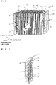
- Fig. 1 is a perspective view of a heat exchanger.
- Fig. 2 is a perspective view of a row straddling header in Fig. 1 .
- Components in Figs. 1 and 2 and other figures, which will be described later, designated by the same reference numerals are the same or equivalent components, which are common throughout the specification. Furthermore, components depicted herein are illustrative and representative and are not meant to be limiting.
- a heat exchanger 1 includes a first heat exchange unit 10 and a second heat exchange unit 20 arranged in a row direction, serving as an air passing direction in which air passes through the heat exchanger 1, an inlet header 30 that serves as a refrigerant divider, a row straddling header 40, and an outlet header 50.
- the first heat exchange unit (outlet heat exchange unit) 10 includes a plurality of fins 11 arranged at regular intervals such that air passes between adjacent fins 11, and a plurality of flat tubes (heat transfer tubes) 12, through which a refrigerant flows, extending through the fins 11 in a direction of arrangement of the fins 11.
- the flat tubes 12 are arranged at multiple levels in a level direction perpendicular to the air passing direction.
- Each flat tube 12 has a plurality of through-holes 12a, serving as a refrigerant passage, as illustrated in Fig. 3 .
- the second heat exchange unit (inlet heat exchange unit) 20 has the same configuration as that of the first heat exchange unit 10 and includes a plurality of fins 21 and a plurality of flat tubes (heat transfer tubes) 22.
- the fin 11 illustrated herein is plate-shaped, the fin does not necessarily have to be a plate-shaped fin.
- wavy fins may be arranged such that the flat tubes 12 and the fins are alternately arranged in the level direction. It is only required that the fins be arranged to allow air to pass between the fins in the air passing direction.
- the inlet header 30 is disposed adjacent to one end of the second heat exchange unit 20 so as to extend in the level direction.
- the inlet header 30 is in communication with all of the flat tubes 22 of the second heat exchange unit 20.
- the inlet header 30 evenly divides the refrigerant flowing from a refrigerant inlet pipe 31 into streams and allows the streams to flow through the flat tubes 22.
- the outlet header 50 is disposed adjacent to one end of the first heat exchange unit 10 so as to extend in the level direction.
- the outlet header 50 is in communication with all of the flat tubes 12 of the first heat exchange unit 10.
- the outlet header 50 combines the refrigerant streams having passed through the flat tubes 12 into a single stream of the refrigerant and allows the refrigerant to flow through a refrigerant outlet pipe 51.
- the row straddling header 40 is disposed adjacent to the other end of each of the first and second heat exchange units 10 and 20 so as to extend in the level direction and straddle across the first and second heat exchange units 10 and 20.
- the row straddling header 40 is hollow and has an interior separated by partitions 41 into a plurality of chambers 42 arranged in the level direction.
- the number of chambers 42 is equal to the number of levels at which the flat tubes 12 and 22 are arranged.
- Each chamber 42 is provided with two through-holes 43 to which the ends of the flat tubes 12 and 22 at the same level are connected.
- the chamber 42 with such a configuration functions as a return passage into which the refrigerant having passed through the flat tube 22 flows and in which this refrigerant turns to the flat tube 12 as indicated by each arrow in Fig. 1 .
- the flat tubes 12 and 22, the fins 11 and 21, the inlet header 30, the row straddling header 40, and the outlet header 50 are made of, for example, aluminum or aluminum alloy.
- the flat tubes 12 and 22, the fins 11 and 21, the inlet header 30, the row straddling header 40, and the outlet header 50 are assembled and joined together by furnace soldering.
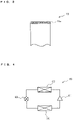
- Fig. 4 is a diagram illustrating a refrigerant circuit of a refrigeration cycle apparatus including the heat exchanger in Fig. 1 .
- a refrigeration cycle apparatus 60 includes a compressor 61, a condenser 62, an expansion valve 63, which serves as a pressure reducing device, and an evaporator 64.
- the heat exchanger 1 is used as at least one of the condenser 62 and the evaporator 64.
- the refrigerant discharged from the compressor 61 flows into the condenser 62, where the refrigerant exchanges heat with air passing through the condenser 62 and thus turns into a high-pressure liquid refrigerant.
- the refrigerant flows out of the condenser 62.
- the high-pressure liquid refrigerant leaving the condenser 62 is pressure-reduced by the expansion valve 63, so that the refrigerant turns into a low-pressure two-phase refrigerant.
- the refrigerant flows into the evaporator 64.
- the low-pressure two-phase refrigerant which has flowed into the evaporator 64, exchanges heat with air passing through the evaporator 64 and thus turns into a low-pressure gas refrigerant.
- the refrigerant is again sucked into the compressor 61.
- Fig. 5(a) is a diagram illustrating flow of the refrigerant in a case where the heat exchanger in Fig. 1 is used as a condenser and illustrates the refrigerant flow when the heat exchanger in Fig. 1 is viewed in plan.
- a thick arrow indicates a refrigerant flow direction and thin arrows A indicate air flow.
- the refrigerant is allowed to flow from a downstream side to an upstream side in the air flow direction A in a return manner (hereinafter, this flow will be referred to as "counter flow”).
- this flow will be referred to as "counter flow”
- a way of allowing the refrigerant to flow from the upstream side to the downstream side in the air flow direction A in a return manner is called "parallel flow”. The parallel flow will be described later.
- the refrigerant flows through the refrigerant inlet pipe 31 into the inlet header 30, where the refrigerant is evenly divided into streams and the refrigerant streams flow into the inlets of the flat tubes 22 of the second heat exchange unit 20.
- the refrigerant streams pass through the flat tubes 22 and flow into the chambers 42 of the row straddling header 40. Each refrigerant stream turns to and flows into the flat tube 12 in the chamber 42.
- the refrigerant flows through the refrigerant outlet pipe 51 to the outside.
- the heat exchanger 1 is used as the condenser 62, the refrigerant can be easily divided evenly because the refrigerant in a gas state flows into the heat exchanger 1. Accordingly, the inlet header 30, serving as a refrigerant divider, may be omitted.
- a component whose interior communicates with the flat tubes 22 of the second heat exchange unit 20 may be used.
- Fig. 6 includes graphs each illustrating the refrigerant temperature distribution in the refrigerant passage from an inlet to an outlet of a condenser.
- the axis of abscissas denotes the refrigerant passage and the axis of ordinates denotes the temperature.
- (a) indicates a case where the refrigerant is a single refrigerant, such as R32 or HFO1234YF, or an azeotropic refrigerant mixture, such as R410A
- (b) indicates a case where the refrigerant is a non-azeotropic refrigerant, such as a mixture of HFO1234YF and R32.
- the gas refrigerant at a high temperature Ta flows into the condenser 62 and exchanges heat with air passing through the condenser 62, so that the temperature of the refrigerant falls to a condensing temperature Tc.
- the refrigerant exhibits a two-phase gas-liquid state such that the temperature of the refrigerant is constant at the condensing temperature Tc, and then turns into a liquid state.
- the temperature of the refrigerant in the liquid state further falls to a low temperature Tb which is lower than the condensing temperature Tc, thus providing subcooling.
- the low-temperature refrigerant flows out of the condenser 62.
- the gas refrigerant at a high temperature Ta' flows into the condenser 62 and exchanges heat with air passing through the condenser 62, so that the temperature of the refrigerant falls to a condensing temperature Tc'.
- the temperature of the non-azeotropic refrigerant in a two-phase gas-liquid state continues to fall because a gas saturation temperature thereof differs from a liquid saturation temperature thereof, so that the refrigerant turns into a liquid state.
- the temperature of the liquid refrigerant further falls to a low temperature Tb' which is lower than the condensing temperature Tc', thus providing subcooling.
- the low-temperature refrigerant flows out of the condenser 62.
- the condenser 62 is required to provide subcooling of, for example, about 10 degrees C. It is therefore necessary to ensure a sufficient amount of heat exchanged with air in a latter half of each refrigerant passage from the inlet to the outlet of the condenser 62.
- the advantages of the counter flow in the condenser 62 are obtained in the use of a single refrigerant or an azeotropic refrigerant, the advantages are particularly enhanced in the use of a non-azeotropic refrigerant.
- the non-azeotropic refrigerant in a two-phase gas-liquid state has a temperature glide because the gas saturation temperature differs from the liquid saturation temperature, as described above. Consequently, the temperature difference between the non-azeotropic refrigerant and air is larger than that between the azeotropic refrigerant and air.
- the advantages are enhanced.
- the heat exchanger 1 is used as the condenser 62.
- the heat exchanger 1 is used as the evaporator 64.
- the counter flow is preferable.
- the refrigerant is a non-azeotropic refrigerant
- the refrigerant in a two-phase gas-liquid state has a temperature glide as described above and the temperature difference is accordingly increased, thus improving the heat exchange performance. Consequently, advantages of the counter flow are greater than those of the parallel flow.
- the evaporator 64 provides superheat to increase the heat exchange performance. Typically, superheat which is about 1 or 2 degrees C is less than subcooling which is 10 degrees C. Accordingly, advantages of the counter flow in the condenser 62 are greater than those in the evaporator 64.
- the configuration of Fig. 1 with the refrigerant counter flow may be used.
- the refrigeration cycle apparatus 60 in Fig. 4 further includes a four-way valve to switch between refrigerant flow directions and the heat exchanger 1 is used as the evaporator 64 or the condenser 62 while alternating between functioning as the evaporator 64 and functioning as the condenser 62, the heat exchanger 1 may be configured as illustrated in Fig. 7 .
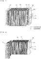
- Fig. 7 is a diagram illustrating a heat exchanger that is used as an evaporator or a condenser selectively.
- dashed-line arrows indicate refrigerant flow in the evaporator 64 and solid-line arrows indicate refrigerant flow in the condenser 62.
- Fig. 7 differs from that of Fig. 1 in that an outlet header 50a functioning as a refrigerant divider to evenly divide the refrigerant into streams is disposed instead of the outlet header 50.
- the parallel flow is provided, specifically, the refrigerant flows through the outlet header 50a, the first heat exchange unit 10, the row straddling header 40, the second heat exchange unit 20, and the inlet header 30 in that order.
- the refrigerant flows into the outlet header 50a when the heat exchanger 1 is used as the evaporator 64.
- the outlet header 50a is allowed to function as a refrigerant divider so that the refrigerant in a two-phase gas-liquid state which has flowed into the outlet header 50a is evenly divided into streams and the refrigerant streams flow into the respective flat tubes 12.
- the counter flow is provided, specifically, the refrigerant flows through the inlet header 30, the second heat exchange unit 20, the row straddling header 40, the first heat exchange unit 10, and the outlet header 50a in that order.
- the refrigerant stream passing through the flat tubes 12 and 22 at each level flows through the isolated refrigerant passage from the inlet to the outlet thereof in the first and second heat exchange units 10 and 20 without mixing with the other refrigerant streams at the other levels. Accordingly, the evenly divided state at the inlet is successfully maintained to the outlet, thus reducing uneven flow division. Consequently, the heat exchange efficiency of the heat exchanger 1 can be enhanced, thus achieving a highly efficient operation of the refrigeration cycle apparatus 60 including the heat exchanger 1.
- the heat exchanger 1 When the heat exchanger 1 is used as the condenser 62, the refrigerant is allowed to flow in a counter flow manner, thus increasing the heat exchange efficiency.
- the advantages of the counter flow are significantly enhanced in the case where the refrigerant enclosed in the refrigeration cycle apparatus 60 is a non-azeotropic refrigerant.
- the configuration of the heat exchanger according to the present invention is not limited to that illustrated in Fig. 1 . Modifications and variations of Embodiment can be made without departing from the scope of the present invention as follows ((1) to (9), for example).
- whether the evenly divided state can be maintained depends on a head difference in each chamber 42.
- An interval between the partitions 41 may be determined in consideration of the head difference. Providing a minimum number of partitions 41 results in a reduction in cost.
- the positions of the partitions 41 may be determined depending on an air velocity distribution in the heat exchanger 1.
- the velocity of air from an air-sending fan to supply air to the heat exchanger 1 is not uniform on the entire surface of the heat exchanger 1. There exists an air velocity distribution.
- an air-sending fan is disposed upstream of the heat exchanger 1.
- the air velocity in upper part of the heat exchanger is accordingly higher than that in lower part thereof.
- gasification in part with high air velocity is promoted more than that in part with low air velocity.
- the refrigerant is easily divided evenly in the part with high air velocity.
- the height (or length in the level direction) of each chamber 42 may be increased (or extended) by increasing the distance between the partitions 41.
- the heat exchanger 1 is generally I-shaped in Embodiment, the heat exchanger 1 may be generally L-shaped, as illustrated in Fig. 8 , such that the heat exchanger 1 is partly bent.
- a generally L-shaped heat exchanger can be formed by bending the generally I-shaped heat exchanger 1 in a direction indicated by an arrow in Fig. 9 into an L-shape.
- the first heat exchange unit 10 should be shorter than the second heat exchange unit 20 in a state before bending as illustrated in Fig. 9 so that ends of the first and second heat exchange units 10 and 20 on each side are aligned in an L-bent state. Aligning the ends of the first and second heat exchange units on each side facilitates arrangement of external pipes connected to the refrigerant inlet pipe 31 and the refrigerant outlet pipe 51.
- Whether to form the heat exchanger 1 into an I-shape or an L-shape may be determined depending on a space for mounting the heat exchanger 1 in a casing that accommodates the heat exchanger 1.
- the shape may be determined so that the heat exchanger 1 can be mounted in an optimized mounting space at high density.
- the shape may be a U-shape or rectangular in addition to the I-shape and the L-shape. In any case, high-density placement in the mounting space allows for high heat exchange efficiency.
- the heat exchanger 1 is configured such that the ends of the first and second heat exchange units 10 and 20 on each side are aligned.
- the inlet header 30 may include an uneven flow division reducing member (for example, orifices to narrow the flow of the refrigerant) to reduce uneven flow division.
- an uneven flow division reducing member for example, orifices to narrow the flow of the refrigerant
- a distributor to substantially evenly divide the refrigerant into streams may be disposed instead of the inlet header 30.
- a refrigerant divider 70 illustrated in Fig. 10 may be used instead of the inlet header 30.
- the refrigerant divider 70 includes a header 71 that communicates with an end of each flat tube 12 and a distributor 74.
- the header 71 has an interior separated by one or more partitions 72 into a plurality of chambers 73 arranged in a longitudinal direction of the header 71.
- Each chamber 73 is connected to the distributor 74 with a capillary tube 75.
- the distributor 74 substantially evenly divides the refrigerant into streams and the refrigerant streams flow through the capillary tubes 75 into the chambers 73.
- Each chamber 73 has a longitudinal length less than that of the header 71 measured when the header 71 has a continuous interior without being separated by the partitions 72. This reduces the influence of a head difference due to gravity, so that the refrigerant can be evenly divided into streams and the refrigerant streams can be supplied to the flat tubes 22 communicating with the respective chambers 73.
- the partition 72 can be disposed not for each level, but every multiple levels, as illustrated in Fig. 10 , in consideration of cost reduction and arrangement of the capillary tubes 75. However, according to the invention the partition 72 is disposed for each level.
- the heat exchange units arranged in two rows are illustrated in Embodiment, the heat exchange units may be arranged in three or more rows. In such a case, the heat exchanger may be configured in a manner similar to the two-row arrangement. Specifically, the heat exchange units at opposite ends in the row direction of the heat exchange units arranged in multiple rows serve as an inlet heat exchange unit into which the refrigerant flows and an outlet heat exchange unit out of which the refrigerant flows.
- First ends of heat transfer tubes arranged at multiple levels of adjacent heat exchange units in the row direction of the heat exchange units arranged in the multiple rows are in communication with the row straddling header, thus providing refrigerant passages through which the refrigerant flows such that the refrigerant flowing from inlets of the heat transfer tubes being arranged at the multiple levels of the inlet heat exchange unit turns in the row straddling header to outlets of the heat transfer tubes being arranged at the multiple levels of the outlet heat exchange unit.
- the row straddling header has an interior separated into a plurality of chambers arranged in the level direction and the refrigerant passage is isolated for its corresponding chamber.
- each heat transfer tube is a flat tube in Embodiment, the heat transfer tube does not necessary have to be a flat tube.
- the heat transfer tube may be a cylindrical tube.
- first heat exchange unit 11 fin 12 heat transfer tube (flat tube) 12a through-hole 20 second heat exchange unit 21 fin 22 heat transfer tube (flat tube) 30 inlet header 31 refrigerant inlet pipe 40 row straddling header 41 partition 42 chamber 43 through-hole 50 outlet header 50a outlet header 51 refrigerant outlet pipe 60 refrigeration cycle apparatus 61 compressor 62 condenser 63 expansion valve 64 evaporator 70 refrigerant divider 71 header 72 partition 73 chamber 74 distributor 75 capillary tube
Description
- The present invention relates to a heat exchanger included in a refrigeration cycle apparatus, such as an air-conditioning apparatus, a refrigeration cycle apparatus including the heat exchanger and an air-conditioning apparatus.
- This kind of heat exchanger includes a plurality of passages. A refrigerant is evenly distributed (or divided into streams) to the passages in order to improve the performance of heat transfer of the heat exchanger. A technique has recently been developed to arrange a plurality of heat exchange units, each including a plurality of fins and a plurality of flat tubes, in a row direction which serves as an air passing direction, in which air passes through the heat exchange units, in order to further increase the efficiency of heat exchange (see,
Patent Literature 1, for example). - In
Patent Literature 1, first ends of the flat tubes of a first heat exchange unit are in communication with first ends of the flat tubes of a second heat exchange unit through a row straddling header. An inlet header evenly divides the refrigerant into streams, which flow through the flat tubes of the first heat exchange unit. The streams temporarily merge into a stream of the refrigerant in the row straddling header, the refrigerant turns to the second heat exchange unit, the refrigerant is again divided into streams which flow through the flat tubes of the second heat exchange unit, the streams merge into a stream of the refrigerant in an outlet header, and the refrigerant flows out of the outlet header. -
US 2005/217838 A1 describes an evaporator for an air conditioning apparatus having an upper and a lower tank and multiple tubes vertically extending and respectively connected to the tanks at upper and lower ends. A fluid passage portion is formed in the lower tank. Multiple drainage recesses are formed in the lower tank at such portions, at which the recesses do not interfere with the fluid passage portion. -
FR 2 864 215 A1 -
US 5 314 013 A describes an evaporator for an automotive air conditioning refrigeration circuit that includes first and second header pipes, a plurality of communicating members which comprise a substantially U-shaped communication path therein, and a corrugated fin unit fixedly disposed between the U-shaped flat pipes. The first and second header pipes are disposed parallel to each other. Each of the U-shaped flat pipes includes a pair of straight portions and a U-shaped curved portion which connects the lower ends of the straight portions. An upper end of one of the straight portions is fixedly and hermetically connected to the first header pipe, and an upper end of the other straight portion is fixedly and hermetically connected to the second header pipe. The pair of the straight portions and the U-shaped curved portion of the U-shaped flat pipe extend along a plane which is parallel to the flow direction of air passing an exterior surface of the evaporator. -
DE 197 19 256 A1 describes a multi-pass flat tube heat exchanger for vehicles with a direction change bottom for the direction change of neighboring passes of the flat tubes. -
EP 0 654 645 A2 describes a heat exchanger according to the preamble ofclaim 1 having flat tubes parallel arranged and spaced apart from each other a predetermined distance in the direction of thickness. The heat exchanger further has a pair of headers to which the ends of the tubes are connected in fluid communication. Each tube has an intermediate bent portion and straight sections separated one from another by the bent portion, and the bent portion is a portion twisted at a predetermined helical angle relative to each straight section. Fins are interposed between the adjacent straight sections, and further fins between the other straight sections. The heat exchanger is easy to manufacture and of an improved efficiency of heat exchange, in spite of the tubes being bent in the direction of their width. - Patent Literature 1:
Japanese Unexamined Patent Application Publication No. 2003-75024 Fig. 1 ) - In
Patent Literature 1, the refrigerant is evenly divided into streams which flow through the flat tubes of the first heat exchange unit and the streams temporarily merge into a stream of the refrigerant in the row straddling header. Accordingly, an initial evenly divided state is not maintained. Disadvantageously, uneven distribution of the refrigerant to the flat tubes of the second heat exchange unit results in a reduction in heat exchange efficiency of the heat exchanger. - The present invention has been made in consideration of the above-described disadvantage. An object of the present invention is to provide a heat exchanger including a plurality of heat exchange units arranged in an air passing direction in which air passes through the heat exchange units, the heat exchanger being capable of reducing uneven division of a refrigerant flowing from inlets of refrigerant passages to outlets thereof and thus exhibiting improved heat exchange performance, to provide a refrigeration cycle apparatus including the heat exchanger and to provide an air-conditioning apparatus.
- This problem is solved by a heat exchanger according to
claim 1, a refrigeration cycle apparatus according toclaim 10 and an air-conditioning apparatus according toclaim 11. Further improvements of the heat exchanger according to the invention are provided in the dependent claims - The present invention provides a heat exchanger including, inter alia, a plurality of heat exchange units each including a plurality of heat transfer tubes through which a refrigerant in a gas-liquid two-phase state flows and a plurality of fins arranged such that air passes between adjacent fins in an air passing direction, the heat transfer tubes being arranged at multiple levels in a level direction perpendicular to the air passing direction, the heat exchange units being arranged in multiple rows in a row direction, serving as the air passing direction. The heat exchanger further includes a row straddling header. The heat exchange units at opposite ends in the row direction of the heat exchange units arranged in the multiple rows serve as an inlet heat exchange unit into which the refrigerant flows and an outlet heat exchange unit out of which the refrigerant flows. First ends of the heat transfer tubes being arranged at the multiple levels of adjacent heat exchange units in the row direction of the heat exchange units arranged in the multiple rows are in communication with the row straddling header to provide refrigerant passages through which the refrigerant flows such that the refrigerant flowing from inlets of the heat transfer tubes being arranged at the multiple levels of the inlet heat exchange unit turns in the row straddling header to outlets of the heat transfer tubes being arranged at the multiple levels of the outlet heat exchange unit. The row straddling header has an inner space separated into a plurality of chambers arranged in the level direction and the refrigerant passage is isolated for each chamber.
- According to the present invention, the heat exchanger is capable of reducing uneven division of the refrigerant throughout the passages because an evenly divided state at an inlet of the heat exchanger is maintained to an outlet thereof, thus exhibiting improved heat exchange performance.
-
- [
Fig. 1] Fig. 1 is a perspective view of a heat exchanger which is not according to the invention but discloses an aspect of the invention. - [
Fig. 2] Fig. 2 is a perspective view of a row straddling header inFig. 1 . - [
Fig. 3] Fig. 3 is a perspective view of a flat tube inFig. 1 . - [
Fig. 4] Fig. 4 is a diagram illustrating a refrigerant circuit of a refrigeration cycle apparatus including theheat exchanger 1 inFig. 1 . - [
Fig. 5] Fig. 5(a) is a diagram illustrating refrigerant flow (counter flow) in a case where the heat exchanger inFig. 1 is used as a condenser andFig. 5(b) is a diagram illustrating parallel flow. - [
Fig. 6] Fig. 6 includes graphs each illustrating a refrigerant temperature distribution in a refrigerant passage extending from an inlet to an outlet of a condenser. - [
Fig. 7] Fig. 7 is a diagram illustrating a heat exchanger used as an evaporator or a condenser while alternating between functioning as an evaporator and functioning as a condenser. - [
Fig. 8] Fig. 8 is a diagram illustrating a heat exchanger formed in a generally L-shape. - [
Fig. 9] Fig. 9 is a diagram illustrating the heat exchanger inFig. 8 in a state before bending. - [
Fig. 10] Fig. 10 is a diagram illustrating another configuration of a refrigerant divider. The embodiment of this invention is a derivation of this configuration, see paragraph 0044. -
Fig. 1 is a perspective view of a heat exchanger.Fig. 2 is a perspective view of a row straddling header inFig. 1 . Components inFigs. 1 and 2 and other figures, which will be described later, designated by the same reference numerals are the same or equivalent components, which are common throughout the specification. Furthermore, components depicted herein are illustrative and representative and are not meant to be limiting. - A
heat exchanger 1 includes a firstheat exchange unit 10 and a secondheat exchange unit 20 arranged in a row direction, serving as an air passing direction in which air passes through theheat exchanger 1, aninlet header 30 that serves as a refrigerant divider, arow straddling header 40, and anoutlet header 50. - The first heat exchange unit (outlet heat exchange unit) 10 includes a plurality of
fins 11 arranged at regular intervals such that air passes betweenadjacent fins 11, and a plurality of flat tubes (heat transfer tubes) 12, through which a refrigerant flows, extending through thefins 11 in a direction of arrangement of thefins 11. Theflat tubes 12 are arranged at multiple levels in a level direction perpendicular to the air passing direction. Eachflat tube 12 has a plurality of through-holes 12a, serving as a refrigerant passage, as illustrated inFig. 3 . The second heat exchange unit (inlet heat exchange unit) 20 has the same configuration as that of the firstheat exchange unit 10 and includes a plurality offins 21 and a plurality of flat tubes (heat transfer tubes) 22. Although thefin 11 illustrated herein is plate-shaped, the fin does not necessarily have to be a plate-shaped fin. For example, wavy fins may be arranged such that theflat tubes 12 and the fins are alternately arranged in the level direction. It is only required that the fins be arranged to allow air to pass between the fins in the air passing direction. - The
inlet header 30 is disposed adjacent to one end of the secondheat exchange unit 20 so as to extend in the level direction. Theinlet header 30 is in communication with all of theflat tubes 22 of the secondheat exchange unit 20. Theinlet header 30 evenly divides the refrigerant flowing from arefrigerant inlet pipe 31 into streams and allows the streams to flow through theflat tubes 22. - The
outlet header 50 is disposed adjacent to one end of the firstheat exchange unit 10 so as to extend in the level direction. Theoutlet header 50 is in communication with all of theflat tubes 12 of the firstheat exchange unit 10. Theoutlet header 50 combines the refrigerant streams having passed through theflat tubes 12 into a single stream of the refrigerant and allows the refrigerant to flow through arefrigerant outlet pipe 51. - The
row straddling header 40 is disposed adjacent to the other end of each of the first and secondheat exchange units heat exchange units row straddling header 40 is hollow and has an interior separated bypartitions 41 into a plurality ofchambers 42 arranged in the level direction. The number ofchambers 42 is equal to the number of levels at which theflat tubes chamber 42 is provided with two through-holes 43 to which the ends of theflat tubes chamber 42 with such a configuration functions as a return passage into which the refrigerant having passed through theflat tube 22 flows and in which this refrigerant turns to theflat tube 12 as indicated by each arrow inFig. 1 . - In the above-described configuration, a passage extending from an inlet of the
flat tube 22 of the secondheat exchange unit 20 to an outlet of theflat tube 12 of the firstheat exchange unit 10 is isolated for each level (or each chamber 42). - The
flat tubes fins inlet header 30, therow straddling header 40, and theoutlet header 50 are made of, for example, aluminum or aluminum alloy. - To make the
heat exchanger 1 with the above-described configuration, theflat tubes fins inlet header 30, therow straddling header 40, and theoutlet header 50 are assembled and joined together by furnace soldering. -
Fig. 4 is a diagram illustrating a refrigerant circuit of a refrigeration cycle apparatus including the heat exchanger inFig. 1 . - A
refrigeration cycle apparatus 60 includes acompressor 61, acondenser 62, anexpansion valve 63, which serves as a pressure reducing device, and anevaporator 64. Theheat exchanger 1 is used as at least one of thecondenser 62 and theevaporator 64. The refrigerant discharged from thecompressor 61 flows into thecondenser 62, where the refrigerant exchanges heat with air passing through thecondenser 62 and thus turns into a high-pressure liquid refrigerant. The refrigerant flows out of thecondenser 62. The high-pressure liquid refrigerant leaving thecondenser 62 is pressure-reduced by theexpansion valve 63, so that the refrigerant turns into a low-pressure two-phase refrigerant. The refrigerant flows into theevaporator 64. The low-pressure two-phase refrigerant, which has flowed into theevaporator 64, exchanges heat with air passing through theevaporator 64 and thus turns into a low-pressure gas refrigerant. The refrigerant is again sucked into thecompressor 61. -
Fig. 5(a) is a diagram illustrating flow of the refrigerant in a case where the heat exchanger inFig. 1 is used as a condenser and illustrates the refrigerant flow when the heat exchanger inFig. 1 is viewed in plan. InFig. 5(a) , a thick arrow indicates a refrigerant flow direction and thin arrows A indicate air flow. - When the
heat exchanger 1 is used as thecondenser 62, the refrigerant is allowed to flow from a downstream side to an upstream side in the air flow direction A in a return manner (hereinafter, this flow will be referred to as "counter flow"). On the other hand, as illustrated inFig. 5(b) , a way of allowing the refrigerant to flow from the upstream side to the downstream side in the air flow direction A in a return manner is called "parallel flow". The parallel flow will be described later. - The flow of the refrigerant in the case where the
heat exchanger 1 is used as thecondenser 62 will now be described with reference toFigs. 1 and4 . - The refrigerant flows through the
refrigerant inlet pipe 31 into theinlet header 30, where the refrigerant is evenly divided into streams and the refrigerant streams flow into the inlets of theflat tubes 22 of the secondheat exchange unit 20. The refrigerant streams pass through theflat tubes 22 and flow into thechambers 42 of therow straddling header 40. Each refrigerant stream turns to and flows into theflat tube 12 in thechamber 42. - Each refrigerant stream, obtained by evenly dividing the refrigerant, flows into the
chamber 42, flows out of thechamber 42 without mixing with the other refrigerant streams in theother chambers 42, and then flows into theflat tube 12 of the firstheat exchange unit 10. Accordingly, the refrigerant streams flowing out of thechambers 42 flow into theflat tubes 12 while being maintained in an evenly divided state. The refrigerant streams having passed through theflat tubes 12 merge into a single stream of the refrigerant in theoutlet header 50. The refrigerant flows through therefrigerant outlet pipe 51 to the outside. When theheat exchanger 1 is used as thecondenser 62, the refrigerant can be easily divided evenly because the refrigerant in a gas state flows into theheat exchanger 1. Accordingly, theinlet header 30, serving as a refrigerant divider, may be omitted. A component whose interior communicates with theflat tubes 22 of the secondheat exchange unit 20 may be used. - Advantages of flowing the refrigerant in counter flow will now be described. The advantages of the refrigerant counter flow are associated with a temperature distribution of the refrigerant in a refrigerant passage from an inlet to an outlet.
-
Fig. 6 includes graphs each illustrating the refrigerant temperature distribution in the refrigerant passage from an inlet to an outlet of a condenser. InFig. 6 , the axis of abscissas denotes the refrigerant passage and the axis of ordinates denotes the temperature. InFig. 6, (a) indicates a case where the refrigerant is a single refrigerant, such as R32 or HFO1234YF, or an azeotropic refrigerant mixture, such as R410A, and (b) indicates a case where the refrigerant is a non-azeotropic refrigerant, such as a mixture of HFO1234YF and R32. Thecondenser 62 performs subcooling, indicated by SC (= Tc - Tb) inFig. 6 , to increase the heat exchange performance. - As regards the single refrigerant or the azeotropic refrigerant mixture, as illustrated in
Fig. 6(a) , the gas refrigerant at a high temperature Ta flows into thecondenser 62 and exchanges heat with air passing through thecondenser 62, so that the temperature of the refrigerant falls to a condensing temperature Tc. The refrigerant exhibits a two-phase gas-liquid state such that the temperature of the refrigerant is constant at the condensing temperature Tc, and then turns into a liquid state. The temperature of the refrigerant in the liquid state further falls to a low temperature Tb which is lower than the condensing temperature Tc, thus providing subcooling. The low-temperature refrigerant flows out of thecondenser 62. - As regards the non-azeotropic refrigerant, as illustrated in
Fig. 6(b) , the gas refrigerant at a high temperature Ta' flows into thecondenser 62 and exchanges heat with air passing through thecondenser 62, so that the temperature of the refrigerant falls to a condensing temperature Tc'. The temperature of the non-azeotropic refrigerant in a two-phase gas-liquid state continues to fall because a gas saturation temperature thereof differs from a liquid saturation temperature thereof, so that the refrigerant turns into a liquid state. The temperature of the liquid refrigerant further falls to a low temperature Tb' which is lower than the condensing temperature Tc', thus providing subcooling. The low-temperature refrigerant flows out of thecondenser 62. - The
condenser 62 is required to provide subcooling of, for example, about 10 degrees C. It is therefore necessary to ensure a sufficient amount of heat exchanged with air in a latter half of each refrigerant passage from the inlet to the outlet of thecondenser 62. - If the parallel flow (see
Fig. 5(b) ) is performed in thecondenser 62, air which has exchanged heat with the refrigerant in the firstheat exchange unit 10 flows through the secondheat exchange unit 20. Accordingly, the difference in temperature between the air and the refrigerant in the latter half of each refrigerant passage would be insufficient. Unfortunately, intended subcooling could not be provided. On the other hand, in the counter flow, the refrigerant in the latter half of the refrigerant passage exchanges heat with air which is to exchange heat with the refrigerant. Consequently, a sufficient temperature difference can be achieved, so that stable subcooling can be provided. - Although the advantages of the counter flow in the
condenser 62 are obtained in the use of a single refrigerant or an azeotropic refrigerant, the advantages are particularly enhanced in the use of a non-azeotropic refrigerant. Specifically, the non-azeotropic refrigerant in a two-phase gas-liquid state has a temperature glide because the gas saturation temperature differs from the liquid saturation temperature, as described above. Consequently, the temperature difference between the non-azeotropic refrigerant and air is larger than that between the azeotropic refrigerant and air. Thus, the advantages are enhanced. - In the above description, the
heat exchanger 1 is used as thecondenser 62. A case where theheat exchanger 1 is used as theevaporator 64 will now be described. Although either the counter flow or the parallel flow may be used when theheat exchanger 1 is used as theevaporator 64, the counter flow is preferable. In the case where theheat exchanger 1 is used as theevaporator 64, if the refrigerant is a non-azeotropic refrigerant, the refrigerant in a two-phase gas-liquid state has a temperature glide as described above and the temperature difference is accordingly increased, thus improving the heat exchange performance. Consequently, advantages of the counter flow are greater than those of the parallel flow. - The
evaporator 64 provides superheat to increase the heat exchange performance. Typically, superheat which is about 1 or 2 degrees C is less than subcooling which is 10 degrees C. Accordingly, advantages of the counter flow in thecondenser 62 are greater than those in theevaporator 64. - If the
heat exchanger 1 is exclusively used as an evaporator or a condenser, the configuration ofFig. 1 with the refrigerant counter flow may be used. If therefrigeration cycle apparatus 60 inFig. 4 further includes a four-way valve to switch between refrigerant flow directions and theheat exchanger 1 is used as theevaporator 64 or thecondenser 62 while alternating between functioning as theevaporator 64 and functioning as thecondenser 62, theheat exchanger 1 may be configured as illustrated inFig. 7 . -
Fig. 7 is a diagram illustrating a heat exchanger that is used as an evaporator or a condenser selectively. InFig. 7 , dashed-line arrows indicate refrigerant flow in theevaporator 64 and solid-line arrows indicate refrigerant flow in thecondenser 62. - The configuration of
Fig. 7 differs from that ofFig. 1 in that anoutlet header 50a functioning as a refrigerant divider to evenly divide the refrigerant into streams is disposed instead of theoutlet header 50. - When the
heat exchanger 1 with such a configuration is used as theevaporator 64, the parallel flow is provided, specifically, the refrigerant flows through theoutlet header 50a, the firstheat exchange unit 10, therow straddling header 40, the secondheat exchange unit 20, and theinlet header 30 in that order. As described above, the refrigerant flows into theoutlet header 50a when theheat exchanger 1 is used as theevaporator 64. Accordingly, theoutlet header 50a is allowed to function as a refrigerant divider so that the refrigerant in a two-phase gas-liquid state which has flowed into theoutlet header 50a is evenly divided into streams and the refrigerant streams flow into the respectiveflat tubes 12. On the other hand, when theheat exchanger 1 is used as thecondenser 62, the counter flow is provided, specifically, the refrigerant flows through theinlet header 30, the secondheat exchange unit 20, therow straddling header 40, the firstheat exchange unit 10, and theoutlet header 50a in that order. - According to Embodiment described above, the refrigerant stream passing through the
flat tubes heat exchange units heat exchanger 1 can be enhanced, thus achieving a highly efficient operation of therefrigeration cycle apparatus 60 including theheat exchanger 1. - When the
heat exchanger 1 is used as thecondenser 62, the refrigerant is allowed to flow in a counter flow manner, thus increasing the heat exchange efficiency. The advantages of the counter flow are significantly enhanced in the case where the refrigerant enclosed in therefrigeration cycle apparatus 60 is a non-azeotropic refrigerant. - The configuration of the heat exchanger according to the present invention is not limited to that illustrated in
Fig. 1 . Modifications and variations of Embodiment can be made without departing from the scope of the present invention as follows ((1) to (9), for example). -
- (1) Although the
partition 41 is provided for each level in therow straddling header 40 in Embodiment, thepartition 41 does not necessarily have to be provided for each level. It is only required that the interior of therow straddling header 40 be separated into a plurality of chambers arranged in the level direction in order to maintain the evenly divided state. - Specifically, whether the evenly divided state can be maintained depends on a head difference in each
chamber 42. An interval between thepartitions 41 may be determined in consideration of the head difference. Providing a minimum number ofpartitions 41 results in a reduction in cost. - (2) The positions of the
partitions 41 may be determined depending on an air velocity distribution in theheat exchanger 1. - The velocity of air from an air-sending fan to supply air to the
heat exchanger 1 is not uniform on the entire surface of theheat exchanger 1. There exists an air velocity distribution. For example, in a multi-air-conditioning apparatus for a building, an air-sending fan is disposed upstream of theheat exchanger 1. The air velocity in upper part of the heat exchanger is accordingly higher than that in lower part thereof. When theheat exchanger 1 is used as theevaporator 64, gasification in part with high air velocity is promoted more than that in part with low air velocity. The refrigerant is easily divided evenly in the part with high air velocity. In part of therow straddling header 40 which communicates with theflat tubes chamber 42 may be increased (or extended) by increasing the distance between thepartitions 41. - (3) Although the
heat exchanger 1 is generally I-shaped in Embodiment, theheat exchanger 1 may be generally L-shaped, as illustrated inFig. 8 , such that theheat exchanger 1 is partly bent. - A generally L-shaped heat exchanger can be formed by bending the generally I-shaped
heat exchanger 1 in a direction indicated by an arrow inFig. 9 into an L-shape. Of course, the firstheat exchange unit 10 should be shorter than the secondheat exchange unit 20 in a state before bending as illustrated inFig. 9 so that ends of the first and secondheat exchange units refrigerant inlet pipe 31 and therefrigerant outlet pipe 51. - Whether to form the
heat exchanger 1 into an I-shape or an L-shape may be determined depending on a space for mounting theheat exchanger 1 in a casing that accommodates theheat exchanger 1. The shape may be determined so that theheat exchanger 1 can be mounted in an optimized mounting space at high density. The shape may be a U-shape or rectangular in addition to the I-shape and the L-shape. In any case, high-density placement in the mounting space allows for high heat exchange efficiency. In such a case, theheat exchanger 1 is configured such that the ends of the first and secondheat exchange units - (4) Although the configuration with the
inlet header 30 as a refrigerant divider has been described above, theinlet header 30 may include an uneven flow division reducing member (for example, orifices to narrow the flow of the refrigerant) to reduce uneven flow division. - (5) As a refrigerant divider, a distributor to substantially evenly divide the refrigerant into streams may be disposed instead of the
inlet header 30. - (6) A
refrigerant divider 70 illustrated inFig. 10 may be used instead of theinlet header 30. - The
refrigerant divider 70 includes aheader 71 that communicates with an end of eachflat tube 12 and adistributor 74. Theheader 71 has an interior separated by one ormore partitions 72 into a plurality ofchambers 73 arranged in a longitudinal direction of theheader 71. Eachchamber 73 is connected to thedistributor 74 with acapillary tube 75. In therefrigerant divider 70, thedistributor 74 substantially evenly divides the refrigerant into streams and the refrigerant streams flow through thecapillary tubes 75 into thechambers 73. - Each
chamber 73 has a longitudinal length less than that of theheader 71 measured when theheader 71 has a continuous interior without being separated by thepartitions 72. This reduces the influence of a head difference due to gravity, so that the refrigerant can be evenly divided into streams and the refrigerant streams can be supplied to theflat tubes 22 communicating with therespective chambers 73. - The
partition 72 can be disposed not for each level, but every multiple levels, as illustrated inFig. 10 , in consideration of cost reduction and arrangement of thecapillary tubes 75. However, according to the invention thepartition 72 is disposed for each level. - (7) Although the configuration with the
row straddling header 40 mounted longitudinally is illustrated in Embodiment, theentire heat exchanger 1 inFig. 1 may be rotated by 90 degrees such that therow straddling header 40 is mounted laterally. In the configuration with the longitudinally mountedrow straddling header 40, the effect of reducing the influence of the head difference is higher than that in the configuration with nopartitions 41. Accordingly, advantages achieved by the present invention are enhanced in the configuration with the longitudinally mountedrow straddling header 40. - (8) Although the heat exchange units arranged in two rows (two-row arrangement) are illustrated in Embodiment, the heat exchange units may be arranged in three or more rows. In such a case, the heat exchanger may be configured in a manner similar to the two-row arrangement. Specifically, the heat exchange units at opposite ends in the row direction of the heat exchange units arranged in multiple rows serve as an inlet heat exchange unit into which the refrigerant flows and an outlet heat exchange unit out of which the refrigerant flows. First ends of heat transfer tubes arranged at multiple levels of adjacent heat exchange units in the row direction of the heat exchange units arranged in the multiple rows are in communication with the row straddling header, thus providing refrigerant passages through which the refrigerant flows such that the refrigerant flowing from inlets of the heat transfer tubes being arranged at the multiple levels of the inlet heat exchange unit turns in the row straddling header to outlets of the heat transfer tubes being arranged at the multiple levels of the outlet heat exchange unit. The row straddling header has an interior separated into a plurality of chambers arranged in the level direction and the refrigerant passage is isolated for its corresponding chamber.
- (9) Although each heat transfer tube is a flat tube in Embodiment, the heat transfer tube does not necessary have to be a flat tube. The heat transfer tube may be a cylindrical tube.
- 1
heat exchanger 10 firstheat exchange unit 11fin 12 heat transfer tube (flat tube) 12a through-hole 20 secondheat exchange unit 21fin 22 heat transfer tube (flat tube) 30inlet header 31refrigerant inlet pipe 40row straddling header 41partition 42chamber 43 through-hole 50outlet header 50a outlet header 51refrigerant outlet pipe 60refrigeration cycle apparatus 61compressor 62condenser 63expansion valve 64evaporator 70refrigerant divider 71header 72partition 73chamber 74distributor 75 capillary tube
Claims (11)
- A heat exchanger (1) comprising:a plurality of heat exchange units (10, 11) each including a plurality of heat transfer tubes (12, 22) through which a refrigerant in a gas-liquid two-phase state flows and a plurality of fins (11, 21) arranged such that air passes between adjacent fins (11, 21) in an air passing direction, the heat transfer tubes (12, 22) being arranged at multiple levels in a level direction perpendicular to the air passing direction, the heat exchange units (10, 11) being arranged in multiple rows in a row direction, serving as the air passing direction; anda row straddling header (40),wherein the heat exchange units (10, 11) at opposite ends in the row direction of the heat exchange units (10, 11) arranged in the multiple rows serve as an inlet heat exchange unit (20) into which the refrigerant flows and an outlet heat exchange unit (10) out of which the refrigerant flows,wherein first ends of the heat transfer tubes (12, 22) being arranged at the multiple levels of adjacent heat exchange units (10,11) in the row direction of the heat exchange units (10, 11) arranged in the multiple rows are in communication with the row straddling header (40) to provide refrigerant passages through which the refrigerant flows such that the refrigerant flowing from inlets of the heat transfer tubes (22) being arranged at the multiple levels of the inlet heat exchange unit (20) turns in the row straddling header (40) to outlets of the heat transfer tubes (12) being arranged at the multiple levels of the outlet heat exchange unit (10),wherein the row straddling header (40) has an interior separated into a plurality of chambers (42) arranged in a vertical direction, which is the level direction, and each of the refrigerant passages is isolated for its corresponding chamber (42),wherein an inlet header is disposed at ends of the heat transfer tubes (12) being arranged at the multiple levels which serve as inlets when the heat exchanger (1) is used as an evaporator, the inlet header is arranged so as to extend in the vertical direction and divides the refrigerant into multiple levels of the heat transfer tubes (12) to flow in, characterized in thateach of the inlet header and the row straddling header has an interior separated into a plurality of chambers arranged in the level direction, each of the refrigerant passages being isolated by corresponding chambers in the inlet header and the row straddling header.
- The heat exchanger (1) of claim 1, wherein the inlet heat exchange unit (20) is disposed in most downstream in the air passing direction and the outlet heat exchange unit (10) is disposed in most upstream in the air passing direction.
- The heat exchanger (1) of claim 2, wherein the heat exchanger (1) is able to be used as an evaporator or a condenser selectively, the refrigerant flows from the outlets to the inlets when the heat exchanger (1) is used as the evaporator, and the refrigerant flows from the inlets to the outlets when the heat exchanger (1) is used as the condenser.
- The heat exchanger (1) of any one of claims 1 to 3, wherein the row straddling header (40) is separated at the multiple levels of the heat transfer tubes (12, 22) into the chambers (42) and each isolated passage is provided for the heat transfer tubes (12, 22) at the same level.
- The heat exchanger (1) of any one of claims 1 to 4, wherein each chamber (42) has, in the level direction, a length determined depending on an air velocity distribution.
- The heat exchanger (1) of any one of claims 1 to 5, wherein the heat exchanger (1) is partly bent and ends of the heat exchange units (10, 11) arranged in the multiple rows on each side are aligned.
- The heat exchanger (1) of any one of claims 1 to 6, further comprising a refrigerant divider (70) that divides the refrigerant into a plurality of streams and allows the refrigerant streams to flow into the heat transfer tubes (12) being arranged at the multiple levels of the inlet heat exchange unit (20), wherein the refrigerant divider (70) includes a header (71) having an interior separated by one or more partitions (72) into a plurality of chambers (73) arranged in a longitudinal direction of the heat exchanger (1) and a distributor (74) configured to substantially evenly divide the refrigerant into streams and each of the chambers (42) is connected to the distributor (74) with a capillary tube (75).
- The heat exchanger (1) of any one of claims 1 to 7, wherein the row straddling header (40) is mounted longitudinally.
- The heat exchanger (1) of any one of claims 1 to 8, wherein each heat transfer tube (12, 22) is a flat tube having a plurality of through-holes (12a) that serve as a refrigerant passage.
- A refrigeration cycle apparatus (60) comprising:a compressor (61);a pressure reducing device (63); andthe heat exchanger (1) of any one of claims 1 to 9.
- An air-conditioning apparatus comprising the refrigeration cycle apparatus (60) of claim 10.
Applications Claiming Priority (2)
| Application Number | Priority Date | Filing Date | Title |
|---|---|---|---|
| PCT/JP2012/002872 WO2013160954A1 (en) | 2012-04-26 | 2012-04-26 | Heat exchanger, and refrigerating cycle device equipped with heat exchanger |
| PCT/JP2013/061878 WO2013161799A1 (en) | 2012-04-26 | 2013-04-23 | Heat exchanger, and refrigerating cycle device equipped with heat exchanger |
Publications (3)
| Publication Number | Publication Date |
|---|---|
| EP2865982A1 EP2865982A1 (en) | 2015-04-29 |
| EP2865982A4 EP2865982A4 (en) | 2016-03-30 |
| EP2865982B1 true EP2865982B1 (en) | 2022-08-31 |
Family
ID=49482331
Family Applications (1)
| Application Number | Title | Priority Date | Filing Date |
|---|---|---|---|
| EP13780638.6A Active EP2865982B1 (en) | 2012-04-26 | 2013-04-23 | Heat exchanger, and refrigerating cycle device equipped with heat exchanger |
Country Status (5)
| Country | Link |
|---|---|
| US (1) | US9689619B2 (en) |
| EP (1) | EP2865982B1 (en) |
| CN (3) | CN108489153A (en) |
| ES (1) | ES2927566T3 (en) |
| WO (2) | WO2013160954A1 (en) |
Families Citing this family (30)
| Publication number | Priority date | Publication date | Assignee | Title |
|---|---|---|---|---|
| JP6688555B2 (en) * | 2013-11-25 | 2020-04-28 | 三星電子株式会社Samsung Electronics Co.,Ltd. | Air conditioner |
| JP6120998B2 (en) * | 2014-01-27 | 2017-04-26 | 三菱電機株式会社 | Laminated header, heat exchanger, and air conditioner |
| JP6333401B2 (en) * | 2014-10-07 | 2018-05-30 | 三菱電機株式会社 | Heat exchanger and air conditioner |
| AU2014408468B2 (en) * | 2014-10-07 | 2018-08-30 | Mitsubishi Electric Corporation | Heat exchanger and air-conditioning apparatus |
| JP5987889B2 (en) * | 2014-11-14 | 2016-09-07 | ダイキン工業株式会社 | Heat exchanger |
| CN104567505A (en) * | 2015-01-17 | 2015-04-29 | 武汉英康汇通电气有限公司 | Heat exchange tube, manufacturing method of heat exchange tube, heat exchange module and heat exchanger |
| CN105091624B (en) * | 2015-08-31 | 2018-01-26 | 湖南华强电气有限公司 | A kind of on-board air conditioner flat pipe heat exchanger |
| JP6529604B2 (en) * | 2015-12-01 | 2019-06-12 | 三菱電機株式会社 | Refrigeration cycle device |
| JP6563115B2 (en) * | 2016-03-31 | 2019-08-21 | 三菱電機株式会社 | Heat exchanger and refrigeration cycle apparatus |
| EP3460358A4 (en) | 2016-05-19 | 2019-05-15 | Mitsubishi Electric Corporation | Outdoor unit and refrigeration cycle device comprising same |
| CN106152622A (en) * | 2016-08-23 | 2016-11-23 | 广州市设计院 | The direct-expansion-type vaporizer of integral type multi-evaporation temperature |
| WO2018078746A1 (en) * | 2016-10-26 | 2018-05-03 | 三菱電機株式会社 | Distributor and heat exchanger |
| CN107270591B (en) * | 2017-07-24 | 2022-11-18 | 江苏必领能源科技有限公司 | Two-phase distributor for falling film evaporator |
| IT201700087168A1 (en) * | 2017-07-28 | 2019-01-28 | Eurochiller S R L | Air condenser |
| JP6631608B2 (en) | 2017-09-25 | 2020-01-15 | ダイキン工業株式会社 | Air conditioner |
| CN108088288A (en) * | 2017-10-31 | 2018-05-29 | 武汉科技大学 | A kind of self-oscillation cavity heat exchanger |
| WO2019116413A1 (en) * | 2017-12-11 | 2019-06-20 | 三菱電機株式会社 | Finless heat exchanger and refrigeration cycle device |
| JP6521116B1 (en) | 2018-01-31 | 2019-05-29 | ダイキン工業株式会社 | Refrigeration apparatus having a heat exchanger or heat exchanger |
| JP6985603B2 (en) * | 2018-01-31 | 2021-12-22 | ダイキン工業株式会社 | Refrigerator with heat exchanger or heat exchanger |
| JP6887075B2 (en) * | 2018-03-19 | 2021-06-16 | パナソニックIpマネジメント株式会社 | Heat exchanger and freezing system using it |
| ES2959955T3 (en) | 2018-04-05 | 2024-02-29 | Mitsubishi Electric Corp | Distributor and heat exchanger |
| CN111366029A (en) * | 2018-12-26 | 2020-07-03 | 浙江盾安热工科技有限公司 | Heat exchanger connecting device and heat exchanger |
| CN111623560B (en) * | 2019-02-27 | 2022-07-29 | 三花控股集团有限公司 | Heat exchanger |
| JP6641542B1 (en) * | 2019-03-05 | 2020-02-05 | 三菱電機株式会社 | Heat exchanger and refrigeration cycle device |
| JP7263072B2 (en) * | 2019-03-20 | 2023-04-24 | サンデン株式会社 | Heat exchanger |
| JP7099392B2 (en) * | 2019-04-03 | 2022-07-12 | トヨタ自動車株式会社 | In-vehicle temperature control device |
| CN112146475B (en) * | 2019-06-28 | 2024-01-02 | 杭州三花研究院有限公司 | Collecting pipe and heat exchanger |
| CN114174758A (en) * | 2019-07-31 | 2022-03-11 | 东芝开利株式会社 | Heat exchanger and refrigeration cycle device |
| CN110542330B (en) * | 2019-09-02 | 2021-02-09 | 枣庄学院 | Water-cooled air cooler capable of being connected in multiple ways |
| JP7278399B2 (en) * | 2019-10-10 | 2023-05-19 | 三菱電機株式会社 | refrigeration cycle equipment |
Family Cites Families (25)
| Publication number | Priority date | Publication date | Assignee | Title |
|---|---|---|---|---|
| JPS6038364U (en) | 1983-08-18 | 1985-03-16 | シャープ株式会社 | Heat exchanger |
| JP3043050B2 (en) * | 1990-11-22 | 2000-05-22 | 昭和アルミニウム株式会社 | Heat exchanger |
| US5314013A (en) | 1991-03-15 | 1994-05-24 | Sanden Corporation | Heat exchanger |
| GB9221927D0 (en) * | 1992-10-17 | 1992-12-02 | Howard Ind Pipework Services L | Panel adapted for coolant through-flow and an article incorporating such panels |
| JPH06300477A (en) * | 1993-04-12 | 1994-10-28 | Matsushita Refrig Co Ltd | Heat exchanger |
| JP3305460B2 (en) * | 1993-11-24 | 2002-07-22 | 昭和電工株式会社 | Heat exchanger |
| JPH0933189A (en) * | 1995-07-20 | 1997-02-07 | Showa Alum Corp | Heat exchanger for outdoor machine |
| JPH09145187A (en) | 1995-11-24 | 1997-06-06 | Hitachi Ltd | Air conditioner |
| DE19719256B4 (en) | 1997-05-07 | 2005-08-18 | Valeo Klimatechnik Gmbh & Co. Kg | More than twin-tube flat tube heat exchanger for motor vehicles with deflection floor and manufacturing process |
| JP4106726B2 (en) | 1998-02-24 | 2008-06-25 | 株式会社デンソー | Refrigerant evaporator |
| JP3774634B2 (en) * | 2001-03-07 | 2006-05-17 | 株式会社日立製作所 | Indoor unit |
| JP4554144B2 (en) | 2001-06-18 | 2010-09-29 | 昭和電工株式会社 | Evaporator |
| US6745827B2 (en) * | 2001-09-29 | 2004-06-08 | Halla Climate Control Corporation | Heat exchanger |
| JP2003214795A (en) * | 2002-01-28 | 2003-07-30 | Mitsubishi Heavy Ind Ltd | Heat exchanger |
| FR2864215B1 (en) | 2003-12-19 | 2011-07-15 | Valeo Climatisation | CIRCUIT ELEMENT FOR HEAT EXCHANGER |
| JP4178472B2 (en) * | 2004-03-18 | 2008-11-12 | 三菱電機株式会社 | Heat exchanger and air conditioner |
| JP4193741B2 (en) * | 2004-03-30 | 2008-12-10 | 株式会社デンソー | Refrigerant evaporator |
| JP2005321137A (en) * | 2004-05-07 | 2005-11-17 | Denso Corp | Heat exchanger |
| US8235101B2 (en) * | 2005-02-02 | 2012-08-07 | Carrier Corporation | Parallel flow heat exchanger for heat pump applications |
| JP4713211B2 (en) * | 2005-04-26 | 2011-06-29 | 株式会社日本クライメイトシステムズ | Heat exchanger |
| US8353330B2 (en) * | 2007-11-02 | 2013-01-15 | Halla Climate Control Corp. | Heat exchanger |
| US8701750B2 (en) * | 2007-11-09 | 2014-04-22 | Halla Visteon Climate Control Corporation | Heat exchanger |
| US8234881B2 (en) * | 2008-08-28 | 2012-08-07 | Johnson Controls Technology Company | Multichannel heat exchanger with dissimilar flow |
| CN201429284Y (en) * | 2009-01-06 | 2010-03-24 | 比亚迪股份有限公司 | Parallel flow air conditioner evaporator |
| CN102278908B (en) * | 2011-09-16 | 2013-06-26 | 四川长虹空调有限公司 | Microchannel heat exchanger |
-
2012
- 2012-04-26 WO PCT/JP2012/002872 patent/WO2013160954A1/en active Application Filing
-
2013
- 2013-04-23 CN CN201810249304.XA patent/CN108489153A/en active Pending
- 2013-04-23 US US14/394,864 patent/US9689619B2/en active Active
- 2013-04-23 WO PCT/JP2013/061878 patent/WO2013161799A1/en active Application Filing
- 2013-04-23 ES ES13780638T patent/ES2927566T3/en active Active
- 2013-04-23 CN CN201380025208.2A patent/CN104334997A/en active Pending
- 2013-04-23 EP EP13780638.6A patent/EP2865982B1/en active Active
- 2013-04-26 CN CN201320219798XU patent/CN203274362U/en not_active Expired - Lifetime
Also Published As
| Publication number | Publication date |
|---|---|
| CN104334997A (en) | 2015-02-04 |
| CN203274362U (en) | 2013-11-06 |
| CN108489153A (en) | 2018-09-04 |
| US9689619B2 (en) | 2017-06-27 |
| EP2865982A4 (en) | 2016-03-30 |
| WO2013160954A1 (en) | 2013-10-31 |
| US20150059401A1 (en) | 2015-03-05 |
| ES2927566T3 (en) | 2022-11-08 |
| WO2013161799A1 (en) | 2013-10-31 |
| EP2865982A1 (en) | 2015-04-29 |
Similar Documents
| Publication | Publication Date | Title |
|---|---|---|
| EP2865982B1 (en) | Heat exchanger, and refrigerating cycle device equipped with heat exchanger | |
| US9494368B2 (en) | Heat exchanger and air conditioner | |
| US9651317B2 (en) | Heat exchanger and air conditioner | |
| EP3037773B1 (en) | Heat exchanger, air conditioner, refrigeration cycle device, and method for producing heat exchanger | |
| EP2853843B1 (en) | A refrigerant distributing device, and heat exchanger equipped with such a refrigerant distributing device | |
| US10309701B2 (en) | Heat exchanger and air conditioner | |
| EP3290851B1 (en) | Layered header, heat exchanger, and air conditioner | |
| EP2857788B1 (en) | Heat exchanger | |
| US20110000255A1 (en) | Microchannel heat exchanger with enhanced refrigerant distribution | |
| JP6061994B2 (en) | Heat exchanger, refrigeration cycle apparatus and air conditioner equipped with this heat exchanger | |
| US10041710B2 (en) | Heat exchanger and air conditioner | |
| WO2018116929A1 (en) | Heat exchanger and air conditioner | |
| CN113330268A (en) | Heat exchanger and air conditioner provided with same | |
| US10197312B2 (en) | Heat exchanger with reduced length distributor tube | |
| US11614260B2 (en) | Heat exchanger for heat pump applications | |
| CN114729795A (en) | Heat exchanger | |
| EP3971507B1 (en) | Heat exchanger and refrigeration cycle device | |
| JP5840291B2 (en) | Heat exchanger, refrigeration cycle apparatus and air conditioner equipped with this heat exchanger |
Legal Events
| Date | Code | Title | Description |
|---|---|---|---|
| PUAI | Public reference made under article 153(3) epc to a published international application that has entered the european phase |
Free format text: ORIGINAL CODE: 0009012 |
|
| STAA | Information on the status of an ep patent application or granted ep patent |
Free format text: STATUS: REQUEST FOR EXAMINATION WAS MADE |
|
| 17P | Request for examination filed |
Effective date: 20141124 |
|
| AK | Designated contracting states |
Kind code of ref document: A1 Designated state(s): AL AT BE BG CH CY CZ DE DK EE ES FI FR GB GR HR HU IE IS IT LI LT LU LV MC MK MT NL NO PL PT RO RS SE SI SK SM TR |
|
| AX | Request for extension of the european patent |
Extension state: BA ME |
|
| DAX | Request for extension of the european patent (deleted) | ||
| RA4 | Supplementary search report drawn up and despatched (corrected) |
Effective date: 20160301 |
|
| RIC1 | Information provided on ipc code assigned before grant |
Ipc: F28F 9/02 20060101AFI20160224BHEP Ipc: F28D 1/053 20060101ALI20160224BHEP Ipc: F25B 39/00 20060101ALI20160224BHEP Ipc: F28F 1/02 20060101ALI20160224BHEP |
|
| STAA | Information on the status of an ep patent application or granted ep patent |
Free format text: STATUS: EXAMINATION IS IN PROGRESS |
|
| 17Q | First examination report despatched |
Effective date: 20210510 |
|
| STAA | Information on the status of an ep patent application or granted ep patent |
Free format text: STATUS: EXAMINATION IS IN PROGRESS |
|
| GRAP | Despatch of communication of intention to grant a patent |
Free format text: ORIGINAL CODE: EPIDOSNIGR1 |
|
| STAA | Information on the status of an ep patent application or granted ep patent |
Free format text: STATUS: GRANT OF PATENT IS INTENDED |
|
| INTG | Intention to grant announced |
Effective date: 20220414 |
|
| GRAS | Grant fee paid |
Free format text: ORIGINAL CODE: EPIDOSNIGR3 |
|
| GRAA | (expected) grant |
Free format text: ORIGINAL CODE: 0009210 |
|
| STAA | Information on the status of an ep patent application or granted ep patent |
Free format text: STATUS: THE PATENT HAS BEEN GRANTED |
|
| AK | Designated contracting states |
Kind code of ref document: B1 Designated state(s): AL AT BE BG CH CY CZ DE DK EE ES FI FR GB GR HR HU IE IS IT LI LT LU LV MC MK MT NL NO PL PT RO RS SE SI SK SM TR |
|
| REG | Reference to a national code |
Ref country code: CH Ref legal event code: EP Ref country code: GB Ref legal event code: FG4D |
|
| REG | Reference to a national code |
Ref country code: AT Ref legal event code: REF Ref document number: 1515585 Country of ref document: AT Kind code of ref document: T Effective date: 20220915 |
|
| REG | Reference to a national code |
Ref country code: DE Ref legal event code: R096 Ref document number: 602013082432 Country of ref document: DE |
|
| REG | Reference to a national code |
Ref country code: IE Ref legal event code: FG4D |
|
| REG | Reference to a national code |
Ref country code: ES Ref legal event code: FG2A Ref document number: 2927566 Country of ref document: ES Kind code of ref document: T3 Effective date: 20221108 |
|
| REG | Reference to a national code |
Ref country code: LT Ref legal event code: MG9D |
|
| REG | Reference to a national code |
Ref country code: NL Ref legal event code: MP Effective date: 20220831 |
|
| PG25 | Lapsed in a contracting state [announced via postgrant information from national office to epo] |
Ref country code: SE Free format text: LAPSE BECAUSE OF FAILURE TO SUBMIT A TRANSLATION OF THE DESCRIPTION OR TO PAY THE FEE WITHIN THE PRESCRIBED TIME-LIMIT Effective date: 20220831 Ref country code: RS Free format text: LAPSE BECAUSE OF FAILURE TO SUBMIT A TRANSLATION OF THE DESCRIPTION OR TO PAY THE FEE WITHIN THE PRESCRIBED TIME-LIMIT Effective date: 20220831 Ref country code: NO Free format text: LAPSE BECAUSE OF FAILURE TO SUBMIT A TRANSLATION OF THE DESCRIPTION OR TO PAY THE FEE WITHIN THE PRESCRIBED TIME-LIMIT Effective date: 20221130 Ref country code: LV Free format text: LAPSE BECAUSE OF FAILURE TO SUBMIT A TRANSLATION OF THE DESCRIPTION OR TO PAY THE FEE WITHIN THE PRESCRIBED TIME-LIMIT Effective date: 20220831 Ref country code: LT Free format text: LAPSE BECAUSE OF FAILURE TO SUBMIT A TRANSLATION OF THE DESCRIPTION OR TO PAY THE FEE WITHIN THE PRESCRIBED TIME-LIMIT Effective date: 20220831 Ref country code: FI Free format text: LAPSE BECAUSE OF FAILURE TO SUBMIT A TRANSLATION OF THE DESCRIPTION OR TO PAY THE FEE WITHIN THE PRESCRIBED TIME-LIMIT Effective date: 20220831 |
|
| REG | Reference to a national code |
Ref country code: AT Ref legal event code: MK05 Ref document number: 1515585 Country of ref document: AT Kind code of ref document: T Effective date: 20220831 |
|
| PG25 | Lapsed in a contracting state [announced via postgrant information from national office to epo] |
Ref country code: PL Free format text: LAPSE BECAUSE OF FAILURE TO SUBMIT A TRANSLATION OF THE DESCRIPTION OR TO PAY THE FEE WITHIN THE PRESCRIBED TIME-LIMIT Effective date: 20220831 Ref country code: IS Free format text: LAPSE BECAUSE OF FAILURE TO SUBMIT A TRANSLATION OF THE DESCRIPTION OR TO PAY THE FEE WITHIN THE PRESCRIBED TIME-LIMIT Effective date: 20221231 Ref country code: HR Free format text: LAPSE BECAUSE OF FAILURE TO SUBMIT A TRANSLATION OF THE DESCRIPTION OR TO PAY THE FEE WITHIN THE PRESCRIBED TIME-LIMIT Effective date: 20220831 Ref country code: GR Free format text: LAPSE BECAUSE OF FAILURE TO SUBMIT A TRANSLATION OF THE DESCRIPTION OR TO PAY THE FEE WITHIN THE PRESCRIBED TIME-LIMIT Effective date: 20221201 |
|
| PG25 | Lapsed in a contracting state [announced via postgrant information from national office to epo] |
Ref country code: SM Free format text: LAPSE BECAUSE OF FAILURE TO SUBMIT A TRANSLATION OF THE DESCRIPTION OR TO PAY THE FEE WITHIN THE PRESCRIBED TIME-LIMIT Effective date: 20220831 Ref country code: RO Free format text: LAPSE BECAUSE OF FAILURE TO SUBMIT A TRANSLATION OF THE DESCRIPTION OR TO PAY THE FEE WITHIN THE PRESCRIBED TIME-LIMIT Effective date: 20220831 Ref country code: PT Free format text: LAPSE BECAUSE OF FAILURE TO SUBMIT A TRANSLATION OF THE DESCRIPTION OR TO PAY THE FEE WITHIN THE PRESCRIBED TIME-LIMIT Effective date: 20230102 Ref country code: DK Free format text: LAPSE BECAUSE OF FAILURE TO SUBMIT A TRANSLATION OF THE DESCRIPTION OR TO PAY THE FEE WITHIN THE PRESCRIBED TIME-LIMIT Effective date: 20220831 Ref country code: CZ Free format text: LAPSE BECAUSE OF FAILURE TO SUBMIT A TRANSLATION OF THE DESCRIPTION OR TO PAY THE FEE WITHIN THE PRESCRIBED TIME-LIMIT Effective date: 20220831 Ref country code: AT Free format text: LAPSE BECAUSE OF FAILURE TO SUBMIT A TRANSLATION OF THE DESCRIPTION OR TO PAY THE FEE WITHIN THE PRESCRIBED TIME-LIMIT Effective date: 20220831 |
|
| PGFP | Annual fee paid to national office [announced via postgrant information from national office to epo] |
Ref country code: FR Payment date: 20230309 Year of fee payment: 11 |
|
| PG25 | Lapsed in a contracting state [announced via postgrant information from national office to epo] |
Ref country code: SK Free format text: LAPSE BECAUSE OF FAILURE TO SUBMIT A TRANSLATION OF THE DESCRIPTION OR TO PAY THE FEE WITHIN THE PRESCRIBED TIME-LIMIT Effective date: 20220831 Ref country code: EE Free format text: LAPSE BECAUSE OF FAILURE TO SUBMIT A TRANSLATION OF THE DESCRIPTION OR TO PAY THE FEE WITHIN THE PRESCRIBED TIME-LIMIT Effective date: 20220831 |
|
| PGFP | Annual fee paid to national office [announced via postgrant information from national office to epo] |
Ref country code: GB Payment date: 20230302 Year of fee payment: 11 |
|
| REG | Reference to a national code |
Ref country code: DE Ref legal event code: R097 Ref document number: 602013082432 Country of ref document: DE |
|
| P01 | Opt-out of the competence of the unified patent court (upc) registered |
Effective date: 20230512 |
|
| PG25 | Lapsed in a contracting state [announced via postgrant information from national office to epo] |
Ref country code: NL Free format text: LAPSE BECAUSE OF FAILURE TO SUBMIT A TRANSLATION OF THE DESCRIPTION OR TO PAY THE FEE WITHIN THE PRESCRIBED TIME-LIMIT Effective date: 20220831 Ref country code: AL Free format text: LAPSE BECAUSE OF FAILURE TO SUBMIT A TRANSLATION OF THE DESCRIPTION OR TO PAY THE FEE WITHIN THE PRESCRIBED TIME-LIMIT Effective date: 20220831 |
|
| PLBE | No opposition filed within time limit |
Free format text: ORIGINAL CODE: 0009261 |
|
| STAA | Information on the status of an ep patent application or granted ep patent |
Free format text: STATUS: NO OPPOSITION FILED WITHIN TIME LIMIT |
|
| PGFP | Annual fee paid to national office [announced via postgrant information from national office to epo] |
Ref country code: ES Payment date: 20230505 Year of fee payment: 11 Ref country code: DE Payment date: 20230228 Year of fee payment: 11 |
|
| 26N | No opposition filed |
Effective date: 20230601 |
|
| PG25 | Lapsed in a contracting state [announced via postgrant information from national office to epo] |
Ref country code: SI Free format text: LAPSE BECAUSE OF FAILURE TO SUBMIT A TRANSLATION OF THE DESCRIPTION OR TO PAY THE FEE WITHIN THE PRESCRIBED TIME-LIMIT Effective date: 20220831 |
|
| PGFP | Annual fee paid to national office [announced via postgrant information from national office to epo] |
Ref country code: TR Payment date: 20230418 Year of fee payment: 11 |
|
| REG | Reference to a national code |
Ref country code: CH Ref legal event code: PL |
|
| PG25 | Lapsed in a contracting state [announced via postgrant information from national office to epo] |
Ref country code: LU Free format text: LAPSE BECAUSE OF NON-PAYMENT OF DUE FEES Effective date: 20230423 |
|
| REG | Reference to a national code |
Ref country code: BE Ref legal event code: MM Effective date: 20230430 |
|
| PG25 | Lapsed in a contracting state [announced via postgrant information from national office to epo] |
Ref country code: MC Free format text: LAPSE BECAUSE OF FAILURE TO SUBMIT A TRANSLATION OF THE DESCRIPTION OR TO PAY THE FEE WITHIN THE PRESCRIBED TIME-LIMIT Effective date: 20220831 |
|
| PG25 | Lapsed in a contracting state [announced via postgrant information from national office to epo] |
Ref country code: MC Free format text: LAPSE BECAUSE OF FAILURE TO SUBMIT A TRANSLATION OF THE DESCRIPTION OR TO PAY THE FEE WITHIN THE PRESCRIBED TIME-LIMIT Effective date: 20220831 Ref country code: LI Free format text: LAPSE BECAUSE OF NON-PAYMENT OF DUE FEES Effective date: 20230430 Ref country code: CH Free format text: LAPSE BECAUSE OF NON-PAYMENT OF DUE FEES Effective date: 20230430 |
|
| REG | Reference to a national code |
Ref country code: IE Ref legal event code: MM4A |
|
| PG25 | Lapsed in a contracting state [announced via postgrant information from national office to epo] |
Ref country code: BE Free format text: LAPSE BECAUSE OF NON-PAYMENT OF DUE FEES Effective date: 20230430 |
|
| PG25 | Lapsed in a contracting state [announced via postgrant information from national office to epo] |
Ref country code: IE Free format text: LAPSE BECAUSE OF NON-PAYMENT OF DUE FEES Effective date: 20230423 |