EP2865768A2 - Continuous casting roller and method for its production - Google Patents
Continuous casting roller and method for its production Download PDFInfo
- Publication number
- EP2865768A2 EP2865768A2 EP20140184621 EP14184621A EP2865768A2 EP 2865768 A2 EP2865768 A2 EP 2865768A2 EP 20140184621 EP20140184621 EP 20140184621 EP 14184621 A EP14184621 A EP 14184621A EP 2865768 A2 EP2865768 A2 EP 2865768A2
- Authority
- EP
- European Patent Office
- Prior art keywords
- layer
- roller
- austenite
- hardening
- radial direction
- Prior art date
- Legal status (The legal status is an assumption and is not a legal conclusion. Google has not performed a legal analysis and makes no representation as to the accuracy of the status listed.)
- Withdrawn
Links
Images

Classifications
-
- B—PERFORMING OPERATIONS; TRANSPORTING
- B22—CASTING; POWDER METALLURGY
- B22D—CASTING OF METALS; CASTING OF OTHER SUBSTANCES BY THE SAME PROCESSES OR DEVICES
- B22D11/00—Continuous casting of metals, i.e. casting in indefinite lengths
- B22D11/12—Accessories for subsequent treating or working cast stock in situ
-
- C—CHEMISTRY; METALLURGY
- C21—METALLURGY OF IRON
- C21D—MODIFYING THE PHYSICAL STRUCTURE OF FERROUS METALS; GENERAL DEVICES FOR HEAT TREATMENT OF FERROUS OR NON-FERROUS METALS OR ALLOYS; MAKING METAL MALLEABLE, e.g. BY DECARBURISATION OR TEMPERING
- C21D9/00—Heat treatment, e.g. annealing, hardening, quenching or tempering, adapted for particular articles; Furnaces therefor
- C21D9/38—Heat treatment, e.g. annealing, hardening, quenching or tempering, adapted for particular articles; Furnaces therefor for roll bodies
-
- B—PERFORMING OPERATIONS; TRANSPORTING
- B22—CASTING; POWDER METALLURGY
- B22D—CASTING OF METALS; CASTING OF OTHER SUBSTANCES BY THE SAME PROCESSES OR DEVICES
- B22D11/00—Continuous casting of metals, i.e. casting in indefinite lengths
- B22D11/12—Accessories for subsequent treating or working cast stock in situ
- B22D11/128—Accessories for subsequent treating or working cast stock in situ for removing
- B22D11/1287—Rolls; Lubricating, cooling or heating rolls while in use
-
- B—PERFORMING OPERATIONS; TRANSPORTING
- B65—CONVEYING; PACKING; STORING; HANDLING THIN OR FILAMENTARY MATERIAL
- B65G—TRANSPORT OR STORAGE DEVICES, e.g. CONVEYORS FOR LOADING OR TIPPING, SHOP CONVEYOR SYSTEMS OR PNEUMATIC TUBE CONVEYORS
- B65G39/00—Rollers, e.g. drive rollers, or arrangements thereof incorporated in roller-ways or other types of mechanical conveyors
- B65G39/10—Arrangements of rollers
- B65G39/12—Arrangements of rollers mounted on framework
- B65G39/18—Arrangements of rollers mounted on framework for guiding loads
-
- C—CHEMISTRY; METALLURGY
- C23—COATING METALLIC MATERIAL; COATING MATERIAL WITH METALLIC MATERIAL; CHEMICAL SURFACE TREATMENT; DIFFUSION TREATMENT OF METALLIC MATERIAL; COATING BY VACUUM EVAPORATION, BY SPUTTERING, BY ION IMPLANTATION OR BY CHEMICAL VAPOUR DEPOSITION, IN GENERAL; INHIBITING CORROSION OF METALLIC MATERIAL OR INCRUSTATION IN GENERAL
- C23C—COATING METALLIC MATERIAL; COATING MATERIAL WITH METALLIC MATERIAL; SURFACE TREATMENT OF METALLIC MATERIAL BY DIFFUSION INTO THE SURFACE, BY CHEMICAL CONVERSION OR SUBSTITUTION; COATING BY VACUUM EVAPORATION, BY SPUTTERING, BY ION IMPLANTATION OR BY CHEMICAL VAPOUR DEPOSITION, IN GENERAL
- C23C8/00—Solid state diffusion of only non-metal elements into metallic material surfaces; Chemical surface treatment of metallic material by reaction of the surface with a reactive gas, leaving reaction products of surface material in the coating, e.g. conversion coatings, passivation of metals
- C23C8/06—Solid state diffusion of only non-metal elements into metallic material surfaces; Chemical surface treatment of metallic material by reaction of the surface with a reactive gas, leaving reaction products of surface material in the coating, e.g. conversion coatings, passivation of metals using gases
- C23C8/28—Solid state diffusion of only non-metal elements into metallic material surfaces; Chemical surface treatment of metallic material by reaction of the surface with a reactive gas, leaving reaction products of surface material in the coating, e.g. conversion coatings, passivation of metals using gases more than one element being applied in one step
- C23C8/30—Carbo-nitriding
- C23C8/32—Carbo-nitriding of ferrous surfaces
-
- C—CHEMISTRY; METALLURGY
- C21—METALLURGY OF IRON
- C21D—MODIFYING THE PHYSICAL STRUCTURE OF FERROUS METALS; GENERAL DEVICES FOR HEAT TREATMENT OF FERROUS OR NON-FERROUS METALS OR ALLOYS; MAKING METAL MALLEABLE, e.g. BY DECARBURISATION OR TEMPERING
- C21D1/00—General methods or devices for heat treatment, e.g. annealing, hardening, quenching or tempering
- C21D1/06—Surface hardening
Definitions
- the present disclosure relates to a continuous casting roller, in particular to a continuous casting roller for continuous casting of steel. It also relates to a method for producing such a roller.
- Continuous casting of steel is the process whereby slabs of steel are continuously cast from molten steel. More specifically, the molten steel is poured from a ladle down into a tundish from which it is conveyed to a water-cooled mould (primary cooling). The molten steel is thereafter solidified into the semi-finished slab for subsequent rolling in the finishing mills. The slab is continuously fed between two tracks formed by a plurality of roll line assemblies, each of which comprises one or several rollers and other parts such as seals and bearings, so as to further shape and cool the slab to the final thickness of the cast material. In this manner, the slab is immediately supported by closely spaced rollers. To increase the rate of solidification, the roll line assemblies, or rollers, are typically water-cooled internally and the slab may be sprayed with large amounts of water as it passes through a spray-chamber (secondary cooling).
- the slab exits the mould vertically (or on a near vertical curved path) into the strand top segment and as it travels through the curved strand it exits the strand in a horizontal position.
- Continuous casting of steel is a demanding process involving high temperatures and large temperature variations.
- water cooling of the slab, or steel strand results in a very corrosive environment.
- the roll line assembly is required to withstand very harsh conditions that are gradually degrading the assembly and its components.
- the material of the rollers may degrade due to corrosion, fatigue and wear.
- the roller or the entire roll line assembly must be replaced or undergo maintenance requiring a lengthy and costly interruption of the continuous casting process.
- Weld cladding is the industry standard method for improving the corrosion, wear, high temperature and fatigue resistance of the rollers. Using this method, the low-alloyed roller is provided with a surface overlay, for example consisting of stainless steel. Weld cladding might be considered a complex process. The method not seldom results in the roll mantle surface having an inhomogeneous microstructure and, consequently, inhomogeneous mechanical properties. Furthermore, it can be difficult to refurbish rollers using weld cladding.
- continuous casting rollers should be high performing as well as simple and cost effective to produce and refurbish. Existing continuous casting rollers can be improved in these respects.
- the objective of the present disclosure is to provide an improved or alternative continuous casting roller.
- Aspects of particular interest include the performance of the continuous casting roller, for example in terms of corrosion, wear, fatigue and high temperature resistance, and the cost and simplicity of its production.
- a continuous casting roller for supporting and transporting hot material in a continuous caster.
- the continuous casting roller has a supporting portion adapted to support hot material.
- the supporting portion has an extension in an axial direction and in a radial direction and comprises a centre portion of low-alloyed steel.
- the centre portion is coaxially enclosed by a plurality of layers which comprises a first layer, wherein the first layer comprises austenite, and a second layer of at least one ceramic material.
- the first layer is coaxially enclosed by the second layer.
- roller will henceforth be used to mean “continuous casting roller”.
- a roller having the structure described above can have a high resistance to corrosion, wear, fatigue and high temperatures. This may lead to a longer overall lifetime of the roller and reduced maintenance costs. Moreover, the roller can be produced by a simple and cost-efficient process and from materials which are commonly available and relatively inexpensive, such as low alloyed steels.
- the layered structure of the roller can result in a roller which combines desirable properties of different materials.
- the layers can have different or similar functions.
- the first layer of hardened austenite can help improve the load-supporting properties of the roller.
- the roller's resistance to corrosion, wear and fatigue can be strengthened by the second layer of at least one ceramic material.
- the third layer of an iron oxide can increase the roller's resistance to corrosion and wear.
- a diffusion layer can be arranged between the centre portion and the first layer, as seen in the radial direction of the supporting portion, so that the diffusion layer is coaxially enclosed by the first layer.
- the centre portion is coaxially enclosed by the diffusion layer.
- Such a diffusion layer defines a foundation in terms of load carrying capacity with a deep and continuous radial transition from the material of the centre portion to the material of the first layer.
- the diffusion layer is a portion of the roller where the roller gradually passes from being formed by the material of the centre portion to being formed by the material of the first layer in terms of increasing level of solid solution hardening and precipitation hardening.
- the diffusion layer may increase the load carrying capacity and the fatigue resistance of the roller.
- the roller can comprise transitional regions between any two sequential layers. Such a transitional region defines a transition from the material of one of the layers to the the material of the other layer.
- the centre portion can comprise less than about 5% by weight of chromium, less than about 4% by weight of nickel and less than about 2% by weight of molybdenum. In terms of performance and economics, low alloyed steels with this composition are particularly suitable for the present invention.
- the first layer can comprise hardened austenite, something which can improve the performance of the roller.
- hardened austenite is meant materials which result from subjecting austenite to a hardening process. Martensite and bainite are examples of such materials.
- the first layer can comprise one of martensite and bainite. Martensite and bainite are hard materials that can help improve the capacity of the roller to withstand heavy loads.
- the second layer can be coaxially enclosed by a third layer of at least one iron oxide.
- the provision of a third layer can improve the performance of the roller.
- the second layer can comprise at least one of ⁇ -phase and ⁇ '-phase.
- the second layer can comprise ⁇ -phase Fe 2-3 (C,N) and/or ⁇ '-phase Fe 4 (C,N).
- the third layer can comprise the iron oxide magnetite (Fe 3 O 4 ).
- the third layer can be the outermost layer as seen in the radial direction.
- the corrosion, wear, fatigue and high temperature resistance properties of ⁇ -phase, ⁇ '-phase and magnetite are such that the provision of layers comprising these compounds can improve the capacity of the roller to withstand the harsh environment in a caster.
- Such layers are typically provided near the outer surface of the supporting portion as seen in the radial direction.
- the third layer can comprise iron oxide wüstite (FeO) and/or hematite (Fe 2 O 3 ).
- the relative amounts of the different iron oxides in the third layer is dependent on technical aspects of the production of the roller, such as the production temperatures.
- the amount of magnetite in the third layer is larger than the amount of wüstite and the amount of hematite.
- some of the properties of magnetite, such its density and adhesive capacity, can make this material particularly suitable for forming the outermost layer of the roller.
- a total case depth can be from about 50 ⁇ m to about 1000 ⁇ m, wherein by “total case depth” is meant the radial distance between the outer surface of the roller and the radius at which the hardness of the roller is 30 HV greater than the hardness of the material of the centre portion.
- a roll line assembly can comprise at least one roller according to the description above and rotation means for rotating a roller.
- the rotation means and the roller are operably connected.
- the roller can be formed in one piece or comprise several components, such as a shaft operatively connected to a roll mantle element.
- the shaft may be rotatably arranged or non-rotatably arranged relative to the roll mantle element.
- a method for producing a continuous casting roller comprises a step of providing a work piece of low alloyed steel with an extension in an axial direction and in a radial direction.
- the method also comprises a step of heat treating the work piece by austenitic nitrocarburizing, whereby an austenite layer and a compound layer are formed.
- austenite layer is meant a layer comprising austenite.
- a diffusion layer can be formed by the step of heat treating the work piece.
- a roller produced according to the method described above can have a high resistance to corrosion, wear, fatigue and high temperatures, which may increase the overall lifetime of the roller and reduce maintenance costs. Moreover, the production costs can be reduced by the use of low alloyed steel, which is relatively inexpensive, and the fact that the heat treatments can be of short duration. Note that, by this method, it is possible to produce a roller according to any of the features and effects as mentioned above with respect to the first aspect of the present invention.
- the work piece can, after having been subjected to the heat treating step, the oxidizing step and the hardening step, form a supporting portion according to the first aspect of the present invention.
- the compound layer can comprise at least one ceramic material.
- the compound layer can comprise at least one of ⁇ -phase and ⁇ '-phase.
- the ⁇ -phase can be ⁇ -phase Fe 2-3 (C,N).
- the ⁇ '-phase can be ⁇ '-phase Fe 4 (C,N).
- the method can comprise a step of oxidizing the heat-treated work piece, whereby an iron oxide layer is formed.
- the method can comprise a step of hardening the austenite layer.
- hardening the austenite layer is meant a process by which the hardness of that layer is increased. Including one or both of these steps can result in a roller with improved performance.
- the iron oxide layer can form the outer surface of the supporting portion as seen in the radial direction.
- the iron oxide layer can comprise magnetite (Fe 2 O 4 ). Magnetite has certain properties, such as a high density and adhesive capacity, that can help improve the wear resistance of the supporting portion.
- the iron oxide layer can comprise wüstite (FeO) and/or hematite (Fe 2 O 3 ). The relative amounts of different iron oxides in the iron oxide layer depend for example on the temperature and atmosphere used during the oxidization process. In some applications, the iron oxide layer can advantageously comprise more magnetite than wüstite and hematite.
- the austenite layer can be hardened by martensitic hardening.
- martensitic hardening is meant a process by which austenite is at least partially transformed into martensite.
- the austenite layer can be hardened by bainitic hardening.
- bainitic hardening is meant a process by which austenite is at least partially transformed into bainite.
- the hardening of the austenite layer can result in a layer comprising one of martensite and bainite being formed. Martensite and bainite are hard materials, and a roller comprising a layer comprising any of these materials may be able to withstand heavy loads.
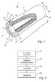
- Figure 1 shows the supporting portion 2 of a continuous casting roller 1 for supporting and transporting hot casted material, such as steel, in a continuous caster.
- the supporting portion 2 has the general shape of a circular cylinder and defines an axial direction A and a radial direction R.
- the two axial end portions 2a, 2b of the supporting portion 2 can be configured to enable operative engagement between the roller 1 and, for example, a supporting structure or bearings. To this end, the two axial end portions 2a, 2b can present for example protrusions and/or depressions.
- the supporting portion 2 can be designed without any through-holes, as in Figure 1 , or can be provided with a straight through-hole (not shown) in the axial direction A for receiving a shaft.
- Such a through-hole can extend circularly around the center of the supporting portion 2 as seen in the radial direction R.
- the supporting portion 2 can be provided with a straight circular through-hole centered on the center axis of the supporting portion 2.
- the supporting portion 2 has an axial length 1 and a diameter d.
- the axial length 1 can for example be from about 100 mm to about 1500 mm.
- the diameter d can for example be from about 100 mm to about 400 mm.
- the supporting portion 2 comprises a centre portion 3 formed by low alloyed steel.
- the centre portion 3 is coaxially enclosed by a plurality of layers arranged sequentially as seen in the radial direction R.
- Each layer has an extension in the radial direction R and in the axial direction A.
- the thickness of a layer, as seen in the radial direction R, can vary in the axial direction A.
- the centre portion 3 is enclosed by a first layer 10.
- a diffusion layer 40 may be arranged between the centre portion 3 and the first layer 10 so that the centre portion 3 is coaxially enclosed by the diffusion layer 40 which, in turn, is coaxially enclosed by the first layer 10.
- the diffusion layer 40 defines a transition region, as seen in the radial direction R, from the material of the centre portion 3 to the material of the first layer 10.
- the diffusion layer 40 can be a portion of the roller 1 where the composition of the roller 1 passes from comprising about 0.1 wt% of nitrogen to comprising about 3 wt% of nitrogen.
- the diffusion layer 40 can be a portion of the roller 1 where the composition of the roller 1 passes from comprising about 0.1 wt% of carbon to comprising about 3 wt% of carbon.
- the diffusion layer 40 can be a portion of the roller 1 where the composition of the roller 1 passes from comprising about 0.1 wt% of nitrogen plus carbon to comprising about 3 wt% of nitrogen plus carbon.
- the diffusion layer 40 can be a portion of the roller 1 which is arranged between the first layer 10 and a portion of the roller 1 having a hardness of about 30 HV greater than the hardness of the centre portion 3.
- the thickness r 40 of the diffusion layer 40 can be from about 50 ⁇ m to about 800 ⁇ m.
- the first layer 10 comprises hardened austenite, for example martensite or bainite. Note that such a layer can comprise austenite, for example austenite that remains unaffected by the hardening process.
- the thickness r 10 of the first layer 10 can be from about 0.5 ⁇ m to about 100 ⁇ m.
- the first layer 10 can have a nitrogen content up to about 5 wt%.
- the first layer 10 can have a carbon content up to about 5 wt%.
- the first layer 10 can have a nitrogen plus carbon content up to about 5 wt%.
- the first layer 10 is coaxially enclosed by a second layer 20. Hence, the first layer 10 is arranged between the diffusion layer 40 and the second layer 20 as seen in the radial direction R.
- the second layer 20 can have a thickness r 20 from about 5 ⁇ m to about 35 ⁇ m.
- the second layer 20 can have a nitrogen content in the range of 5-12 wt%.
- the second layer 20 can have a carbon content in the range of 5-12 wt%.
- the second layer 20 can have a nitrogen plus carbon content in the range of 5-12 wt%.
- the second layer 20 comprises at least one ceramic material, for example ⁇ -phase Fe 2-3 (C,N) and/or y'-phase Fe 4 (C,N).
- the second layer 20 can be coaxially enclosed by a third layer 30 of at least one iron oxide, for example magnetite (Fe 3 O 4 ), wüstite (FeO) and/or hematite (Fe 2 O 3 ).
- the second layer 20 is thus arranged between the first layer 10 and the third layer 30 as seen in the radial direction R.
- the third layer 30 can form an outer surface 2c, as seen in the radial direction R, of the supporting portion 2.
- the third layer 30 can have a thickness r 30 from about 0.5 ⁇ m to about 3 ⁇ m.
- any two radially sequential layers there may be a transitional region in which the material of the supporting portion varies, as seen in the radial direction R, from the material of one of the layers to the material of the other layer.
- FIG. 2 is a flowchart of some of the steps of a method for producing a continuous casting roller 1 according to the present invention.
- a number of method steps, which can impact the properties of the finished product in terms of resistance to corrosion, wear, fatigue and high temperature are involved in producing the roller 1.
- step S1 a work piece of low alloyed steel is provided.
- the work piece has an extension in a radial direction R and in an axial direction A.
- the work piece has an axial length 1, which can be from about 100 mm to about 1500 mm, and a diameter d, which can be from about 100 mm to about 400 mm.
- step S2 the work piece is heat treated by an austenitic nitrocarburizing process.
- the process medium of the austenitic nitrocarburizing process can be chosen from the group consisting of a gas, a liquid or a plasma.
- the process medium of the austenitic nitrocarburizing process comprises nitrogen and carbon as active elements. Austenitic nitrocarburizing is deemed to be known to the skilled person and thus require no further description.
- An austenite layer and a compound layer are formed as a result of the austenitic nitrocarburizing process.
- a diffusion layer is formed as well.
- the compound layer comprises at least one ceramic material, for example ⁇ -phase Fe 2-3 (C,N) and/or ⁇ '-phase Fe 4 (C,N).
- Each of the compound layer and the austenite layer has an extension in the radial direction R and in the axial direction A, and the layers are arranged so that the compound layer coaxially encloses the austenite layer.
- the austenite layer coaxially encloses the diffusion layer.
- the austenite layer is arranged between the diffusion layer and the compound layer seen in the radial direction R.
- the method can comprise a step S3 in which the heat-treated work piece is oxidized.
- Water, air or laughing gas (N 2 O) can be used as a source of oxygen during this process.
- the oxidization results in the formation of an iron oxide layer comprising at least one iron oxide.
- Magnetite (Fe 3 O 4 ), wüstite (FeO) and hematite (Fe 2 O 3 ), or any combination thereof, can form part of the iron oxide layer.
- the method can comprise a step S4 in which the austenite layer is hardened.
- the hardening of the austenite layer can be achieved through martensitic hardening which transforms austenite into martensite. This process involves a phase transformation of austenite to martensite. Note that residues of austenite may remain after the martensitic hardening.
- Martensitic hardening can be achieved through quenching (rapid cooling) from the austenitic temperature region to very low temperatures.
- the martensite start temperature i.e. the temperature at which austenite starts transforming into martensite, lies below room temperature because of the high levels of nitrogen used in the austenitic nitrocarburizing process.
- This shear deformation process can produce a microstructure consisting of elongated grains (laths), which can be approximately 0.5 ⁇ m across, with a very high dislocation density that can result in a hardness of up to 750 HV (61 HRC).
- the hardening of the austenite layer in step S4 can be achieved through bainitic hardening which transforms austenite into bainite.
- This process involves a phase transformation of austenite to bainite.
- residues of austenite may remain after the bainitic hardening.
- the bainitic hardening is typically a tempering process which is carried out in the temperature range of 250-400°C and which causes the austenite to decompose into a lower bainitic structure.
- the new microstructure can comprise fine ferrite ( ⁇ ) plates with cementite ( ⁇ ') particles precipitated within the plates. These ferrite plates, which can be approximately 0.2 ⁇ m wide and 10 ⁇ m long, are usually also separated by cementite particles. This fine microstructure can result in a hardness up to about 1000 HV (69 HRC).
- step S3 occurs before the step of hardening the austenite layer, step S4.
- step S4 can occur before the step of oxidizing the heat-treated work piece, step S3.
- the work piece can, after having been subjected to the heat treating step, the oxidizing step and the hardening step, form a supporting portion 2 as described in connection with figure 1 .
- a roller 1 with a supporting portion 2 which has an extension in an axial direction A and in a radial direction R and which has a centre portion 3 of low alloyed steel coaxially enclosed by a plurality of layers.
- Each layer has an extension in the radial direction R and in the axial direction A.
- the thickness of a layer, as seen in the radial direction R can vary in the axial direction A.
- the layers can comprise a first layer 10 in the form of a hardened austenite layer.
- the first layer 10 is coaxially enclosed by a second layer 20 in the form of a compound layer comprising at least one ceramic material.
- the second layer 20 can be coaxially enclosed by a third layer 30 in the form of an iron oxide layer comprising at least one iron oxide.
- the second layer 20 is arranged between the first layer 10 and the third layer 30 as seen in the radial direction R
- the third layer 30 can form an outer surface 2c, as seen in the radial direction R, of the supporting portion 2.
- the centre portion 3 is the radially innermost portion of the supporting portion 2.
- the centre portion 3 can be coaxially enclosed by a diffusion layer 40 which, in turn, is coaxially enclosed by the first layer 10.
- the diffusion layer 40 is arranged between the centre portion 3 and the first layer 10 as seen in the radial direction R.
- the composition of the supporting portion 2 varies, as seen in the radial direction R, from the material of center portion 3 to the material of the first layer 10.
- the total case depth i.e. the depth in the radial direction R of the material affected by the steps S2 to S4, can be from about 50 ⁇ m to about 1000 ⁇ m.
- roller 1 may comprise transitional regions between any two sequential layers. Such a transitional region defines a transition from the material of one of the layers to the the material of the other layer.
- FIG 3 shows a roll line assembly 4 comprising two continuous casting rollers 1 arranged in the axial direction A.
- the rollers 1 have supporting portions 2.
- Rotation means 5 in the form of bearings 5 can be arranged by the end regions 2a, 2b of the supporting portions 2 so as to enable axial rotation of the supporting portions 2.
- Each bearing 5 can be encapsulated by a supporting block 6 which can have a base portion 6a.
- the base portions 6 can be adapted for mounting on an external structure 7.
- the roll line assembly 4 may further comprise one or several sealing elements (not shown), for example in order to protect the bearings 5 from the hot slab.
- the roller 1 can be formed in one piece.
- the roller 1 can consist of several components, for example a shaft operatively connected to a roll mantle element.
- the shaft may be rotatable or non-rotable.
- the roller 1 is mounted in a roll line assembly 4.
- the roller 1 rotates about an axis in the axial direction A, whereby a material, such as hot steel, is supported by the supporting portion 2 and transported along a direction that is substantially perpendicular to the axial direction A.
- a roller 1 which can have a high resistance to corrosion, wear, fatigue and high temperatures. This may lead to a longer overall lifetime of the roller 1 and reduced maintenance costs. Moreover, the roller 1 can be produced by a simple and cost-efficient process and from materials which are commonly available and relatively inexpensive, such as low alloyed steels.
Landscapes
- Chemical & Material Sciences (AREA)
- Engineering & Computer Science (AREA)
- Mechanical Engineering (AREA)
- Organic Chemistry (AREA)
- Materials Engineering (AREA)
- Metallurgy (AREA)
- Chemical Kinetics & Catalysis (AREA)
- Physics & Mathematics (AREA)
- Thermal Sciences (AREA)
- Crystallography & Structural Chemistry (AREA)
- Rolls And Other Rotary Bodies (AREA)
- Pistons, Piston Rings, And Cylinders (AREA)
- Rollers For Roller Conveyors For Transfer (AREA)
- Heat Treatment Of Articles (AREA)
Abstract
Description
- The present disclosure relates to a continuous casting roller, in particular to a continuous casting roller for continuous casting of steel. It also relates to a method for producing such a roller.
- Continuous casting of steel is the process whereby slabs of steel are continuously cast from molten steel. More specifically, the molten steel is poured from a ladle down into a tundish from which it is conveyed to a water-cooled mould (primary cooling). The molten steel is thereafter solidified into the semi-finished slab for subsequent rolling in the finishing mills. The slab is continuously fed between two tracks formed by a plurality of roll line assemblies, each of which comprises one or several rollers and other parts such as seals and bearings, so as to further shape and cool the slab to the final thickness of the cast material. In this manner, the slab is immediately supported by closely spaced rollers. To increase the rate of solidification, the roll line assemblies, or rollers, are typically water-cooled internally and the slab may be sprayed with large amounts of water as it passes through a spray-chamber (secondary cooling).
- In a curved apron casting machine, the slab exits the mould vertically (or on a near vertical curved path) into the strand top segment and as it travels through the curved strand it exits the strand in a horizontal position. Continuous casting of steel is a demanding process involving high temperatures and large temperature variations. Furthermore, water cooling of the slab, or steel strand, results in a very corrosive environment. Accordingly, the roll line assembly is required to withstand very harsh conditions that are gradually degrading the assembly and its components. As an example, the material of the rollers may degrade due to corrosion, fatigue and wear. Eventually, the roller or the entire roll line assembly must be replaced or undergo maintenance requiring a lengthy and costly interruption of the continuous casting process.
- One roll line assembly component that is particularly subjected to degradation is the roller, since it is in direct contact with the hot steel slab. The roller is therefore an important and determining factor in the overall lifetime of a roll line assembly. Weld cladding is the industry standard method for improving the corrosion, wear, high temperature and fatigue resistance of the rollers. Using this method, the low-alloyed roller is provided with a surface overlay, for example consisting of stainless steel. Weld cladding might be considered a complex process. The method not seldom results in the roll mantle surface having an inhomogeneous microstructure and, consequently, inhomogeneous mechanical properties. Furthermore, it can be difficult to refurbish rollers using weld cladding.
- It is desirable that continuous casting rollers should be high performing as well as simple and cost effective to produce and refurbish. Existing continuous casting rollers can be improved in these respects.
- The objective of the present disclosure is to provide an improved or alternative continuous casting roller. Aspects of particular interest include the performance of the continuous casting roller, for example in terms of corrosion, wear, fatigue and high temperature resistance, and the cost and simplicity of its production.
- The invention is defined by the independent claim. Embodiments are set forth in the dependent claims, the description and the drawings.
- According to a first aspect of the present invention, there is provided a continuous casting roller for supporting and transporting hot material in a continuous caster. The continuous casting roller has a supporting portion adapted to support hot material. The supporting portion has an extension in an axial direction and in a radial direction and comprises a centre portion of low-alloyed steel. The centre portion is coaxially enclosed by a plurality of layers which comprises a first layer, wherein the first layer comprises austenite, and a second layer of at least one ceramic material. The first layer is coaxially enclosed by the second layer.
- For brevity, the term "roller" will henceforth be used to mean "continuous casting roller".
- A roller having the structure described above can have a high resistance to corrosion, wear, fatigue and high temperatures. This may lead to a longer overall lifetime of the roller and reduced maintenance costs. Moreover, the roller can be produced by a simple and cost-efficient process and from materials which are commonly available and relatively inexpensive, such as low alloyed steels.
- The layered structure of the roller can result in a roller which combines desirable properties of different materials. The layers can have different or similar functions. For example, the first layer of hardened austenite can help improve the load-supporting properties of the roller. The roller's resistance to corrosion, wear and fatigue can be strengthened by the second layer of at least one ceramic material. The third layer of an iron oxide can increase the roller's resistance to corrosion and wear.
- A diffusion layer can be arranged between the centre portion and the first layer, as seen in the radial direction of the supporting portion, so that the diffusion layer is coaxially enclosed by the first layer. The centre portion is coaxially enclosed by the diffusion layer. Such a diffusion layer defines a foundation in terms of load carrying capacity with a deep and continuous radial transition from the material of the centre portion to the material of the first layer. Stated in another way, the diffusion layer is a portion of the roller where the roller gradually passes from being formed by the material of the centre portion to being formed by the material of the first layer in terms of increasing level of solid solution hardening and precipitation hardening. The diffusion layer may increase the load carrying capacity and the fatigue resistance of the roller.
- The roller can comprise transitional regions between any two sequential layers. Such a transitional region defines a transition from the material of one of the layers to the the material of the other layer.
- The centre portion can comprise less than about 5% by weight of chromium, less than about 4% by weight of nickel and less than about 2% by weight of molybdenum. In terms of performance and economics, low alloyed steels with this composition are particularly suitable for the present invention.
- The first layer can comprise hardened austenite, something which can improve the performance of the roller. By "hardened austenite" is meant materials which result from subjecting austenite to a hardening process. Martensite and bainite are examples of such materials. The first layer can comprise one of martensite and bainite. Martensite and bainite are hard materials that can help improve the capacity of the roller to withstand heavy loads.
- The second layer can be coaxially enclosed by a third layer of at least one iron oxide. The provision of a third layer can improve the performance of the roller. The second layer can comprise at least one of ε-phase and γ'-phase. For example, the second layer can comprise ε-phase Fe2-3(C,N) and/or γ'-phase Fe4(C,N). The third layer can comprise the iron oxide magnetite (Fe3O4). The third layer can be the outermost layer as seen in the radial direction. The corrosion, wear, fatigue and high temperature resistance properties of ε-phase, γ'-phase and magnetite are such that the provision of layers comprising these compounds can improve the capacity of the roller to withstand the harsh environment in a caster. Such layers are typically provided near the outer surface of the supporting portion as seen in the radial direction.
- The third layer can comprise iron oxide wüstite (FeO) and/or hematite (Fe2O3). The relative amounts of the different iron oxides in the third layer is dependent on technical aspects of the production of the roller, such as the production temperatures. According to a variant of the roller, the amount of magnetite in the third layer is larger than the amount of wüstite and the amount of hematite. In some applications, some of the properties of magnetite, such its density and adhesive capacity, can make this material particularly suitable for forming the outermost layer of the roller.
- A total case depth can be from about 50 µm to about 1000 µm, wherein by "total case depth" is meant the radial distance between the outer surface of the roller and the radius at which the hardness of the roller is 30 HV greater than the hardness of the material of the centre portion.
- A roll line assembly can comprise at least one roller according to the description above and rotation means for rotating a roller. The rotation means and the roller are operably connected. The roller can be formed in one piece or comprise several components, such as a shaft operatively connected to a roll mantle element. The shaft may be rotatably arranged or non-rotatably arranged relative to the roll mantle element.
- According to a second aspect of the present invention, there is provided a method for producing a continuous casting roller. The method comprises a step of providing a work piece of low alloyed steel with an extension in an axial direction and in a radial direction. The method also comprises a step of heat treating the work piece by austenitic nitrocarburizing, whereby an austenite layer and a compound layer are formed. By "austenite layer" is meant a layer comprising austenite. A diffusion layer can be formed by the step of heat treating the work piece.
- A roller produced according to the method described above can have a high resistance to corrosion, wear, fatigue and high temperatures, which may increase the overall lifetime of the roller and reduce maintenance costs. Moreover, the production costs can be reduced by the use of low alloyed steel, which is relatively inexpensive, and the fact that the heat treatments can be of short duration. Note that, by this method, it is possible to produce a roller according to any of the features and effects as mentioned above with respect to the first aspect of the present invention. In particular, the work piece can, after having been subjected to the heat treating step, the oxidizing step and the hardening step, form a supporting portion according to the first aspect of the present invention.
- The compound layer can comprise at least one ceramic material. The compound layer can comprise at least one of ε-phase and γ'-phase. The ε-phase can be ε-phase Fe2-3(C,N). The γ'-phase can be γ'-phase Fe4(C,N). These compounds can improve the corrosion, wear, fatigue and high temperature resistance of the supporting portion and are typically provided near the outer surface of the supporting portion as seen in the radial direction.
- The method can comprise a step of oxidizing the heat-treated work piece, whereby an iron oxide layer is formed. The method can comprise a step of hardening the austenite layer. By "hardening the austenite layer" is meant a process by which the hardness of that layer is increased. Including one or both of these steps can result in a roller with improved performance.
- The iron oxide layer can form the outer surface of the supporting portion as seen in the radial direction. The iron oxide layer can comprise magnetite (Fe2O4). Magnetite has certain properties, such as a high density and adhesive capacity, that can help improve the wear resistance of the supporting portion. The iron oxide layer can comprise wüstite (FeO) and/or hematite (Fe2O3). The relative amounts of different iron oxides in the iron oxide layer depend for example on the temperature and atmosphere used during the oxidization process. In some applications, the iron oxide layer can advantageously comprise more magnetite than wüstite and hematite.
- The austenite layer can be hardened by martensitic hardening. By "martensitic hardening" is meant a process by which austenite is at least partially transformed into martensite. Alternatively, the austenite layer can be hardened by bainitic hardening. By "bainitic hardening" is meant a process by which austenite is at least partially transformed into bainite. Hence, the hardening of the austenite layer can result in a layer comprising one of martensite and bainite being formed. Martensite and bainite are hard materials, and a roller comprising a layer comprising any of these materials may be able to withstand heavy loads.
- The various aspects of the invention, including its particular features and advantages, will be readily understood from the following detailed description and the accompanying drawings, in which:
-
Figure 1 is a cross-sectional perspective view of a roller showing its inner layered structure; -
Figure 2 is a flowchart of some of the steps of a method for producing a roller; and -
Figure 3 is a schematic perspective view of some of the components of a roll line assembly. - The figures are not drawn to scale. As illustrated in the figures, the sizes of layers and regions are exaggerated for illustrative purposes and, thus, are provided to illustrate the general structures of embodiments of the present invention.
- The present invention will now be described more fully hereinafter with reference to the accompanying drawings, in which exemplary embodiments of the invention are shown. The invention may, however, be embodied in many different forms and should not be construed as limited to the embodiments set forth herein; rather, these embodiments are provided for thoroughness and completeness. Like reference characters refer to like elements throughout the description.
-
Figure 1 shows the supportingportion 2 of acontinuous casting roller 1 for supporting and transporting hot casted material, such as steel, in a continuous caster. The supportingportion 2 has the general shape of a circular cylinder and defines an axial direction A and a radial direction R. The twoaxial end portions portion 2 can be configured to enable operative engagement between theroller 1 and, for example, a supporting structure or bearings. To this end, the twoaxial end portions portion 2 can be designed without any through-holes, as inFigure 1 , or can be provided with a straight through-hole (not shown) in the axial direction A for receiving a shaft. Such a through-hole can extend circularly around the center of the supportingportion 2 as seen in the radial direction R. Stated in another way, the supportingportion 2 can be provided with a straight circular through-hole centered on the center axis of the supportingportion 2. The supportingportion 2 has anaxial length 1 and a diameter d. Theaxial length 1 can for example be from about 100 mm to about 1500 mm. The diameter d can for example be from about 100 mm to about 400 mm. - The supporting
portion 2 comprises acentre portion 3 formed by low alloyed steel. Thecentre portion 3 is coaxially enclosed by a plurality of layers arranged sequentially as seen in the radial direction R. Each layer has an extension in the radial direction R and in the axial direction A. The thickness of a layer, as seen in the radial direction R, can vary in the axial direction A. - The
centre portion 3 is enclosed by afirst layer 10. Adiffusion layer 40 may be arranged between thecentre portion 3 and thefirst layer 10 so that thecentre portion 3 is coaxially enclosed by thediffusion layer 40 which, in turn, is coaxially enclosed by thefirst layer 10. Thediffusion layer 40 defines a transition region, as seen in the radial direction R, from the material of thecentre portion 3 to the material of thefirst layer 10. Thediffusion layer 40 can be a portion of theroller 1 where the composition of theroller 1 passes from comprising about 0.1 wt% of nitrogen to comprising about 3 wt% of nitrogen. Thediffusion layer 40 can be a portion of theroller 1 where the composition of theroller 1 passes from comprising about 0.1 wt% of carbon to comprising about 3 wt% of carbon. Thediffusion layer 40 can be a portion of theroller 1 where the composition of theroller 1 passes from comprising about 0.1 wt% of nitrogen plus carbon to comprising about 3 wt% of nitrogen plus carbon. Thediffusion layer 40 can be a portion of theroller 1 which is arranged between thefirst layer 10 and a portion of theroller 1 having a hardness of about 30 HV greater than the hardness of thecentre portion 3. The thickness r40 of thediffusion layer 40 can be from about 50 µm to about 800 µm. Infigure 1 , thefirst layer 10 comprises hardened austenite, for example martensite or bainite. Note that such a layer can comprise austenite, for example austenite that remains unaffected by the hardening process. The thickness r10 of thefirst layer 10 can be from about 0.5 µm to about 100 µm. Thefirst layer 10 can have a nitrogen content up to about 5 wt%. Thefirst layer 10 can have a carbon content up to about 5 wt%. Thefirst layer 10 can have a nitrogen plus carbon content up to about 5 wt%. Thefirst layer 10 is coaxially enclosed by asecond layer 20. Hence, thefirst layer 10 is arranged between thediffusion layer 40 and thesecond layer 20 as seen in the radial direction R. Thesecond layer 20 can have a thickness r20 from about 5 µm to about 35 µm. Thesecond layer 20 can have a nitrogen content in the range of 5-12 wt%. Thesecond layer 20 can have a carbon content in the range of 5-12 wt%. Thesecond layer 20 can have a nitrogen plus carbon content in the range of 5-12 wt%. Thesecond layer 20 comprises at least one ceramic material, for example ε-phase Fe2-3(C,N) and/or y'-phase Fe4(C,N). - The
second layer 20 can be coaxially enclosed by athird layer 30 of at least one iron oxide, for example magnetite (Fe3O4), wüstite (FeO) and/or hematite (Fe2O3). Thesecond layer 20 is thus arranged between thefirst layer 10 and thethird layer 30 as seen in the radial direction R. Thethird layer 30 can form anouter surface 2c, as seen in the radial direction R, of the supportingportion 2. Thethird layer 30 can have a thickness r30 from about 0.5 µm to about 3 µm. - Between any two radially sequential layers, there may be a transitional region in which the material of the supporting portion varies, as seen in the radial direction R, from the material of one of the layers to the material of the other layer.
-
Figure 2 is a flowchart of some of the steps of a method for producing acontinuous casting roller 1 according to the present invention. A number of method steps, which can impact the properties of the finished product in terms of resistance to corrosion, wear, fatigue and high temperature are involved in producing theroller 1. In step S1, a work piece of low alloyed steel is provided. The work piece has an extension in a radial direction R and in an axial direction A. The work piece has anaxial length 1, which can be from about 100 mm to about 1500 mm, and a diameter d, which can be from about 100 mm to about 400 mm. - In step S2, the work piece is heat treated by an austenitic nitrocarburizing process. The process medium of the austenitic nitrocarburizing process can be chosen from the group consisting of a gas, a liquid or a plasma. The process medium of the austenitic nitrocarburizing process comprises nitrogen and carbon as active elements. Austenitic nitrocarburizing is deemed to be known to the skilled person and thus require no further description.
- An austenite layer and a compound layer are formed as a result of the austenitic nitrocarburizing process. Typically, a diffusion layer is formed as well. The compound layer comprises at least one ceramic material, for example ε-phase Fe2-3(C,N) and/or γ'-phase Fe4(C,N). Each of the compound layer and the austenite layer has an extension in the radial direction R and in the axial direction A, and the layers are arranged so that the compound layer coaxially encloses the austenite layer. The austenite layer coaxially encloses the diffusion layer. Hence, the austenite layer is arranged between the diffusion layer and the compound layer seen in the radial direction R.
- The method can comprise a step S3 in which the heat-treated work piece is oxidized. Water, air or laughing gas (N2O) can be used as a source of oxygen during this process. The oxidization results in the formation of an iron oxide layer comprising at least one iron oxide. Magnetite (Fe3O4), wüstite (FeO) and hematite (Fe2O3), or any combination thereof, can form part of the iron oxide layer.
- The method can comprise a step S4 in which the austenite layer is hardened. The hardening of the austenite layer can be achieved through martensitic hardening which transforms austenite into martensite. This process involves a phase transformation of austenite to martensite. Note that residues of austenite may remain after the martensitic hardening. Martensitic hardening can be achieved through quenching (rapid cooling) from the austenitic temperature region to very low temperatures. The martensite start temperature, i.e. the temperature at which austenite starts transforming into martensite, lies below room temperature because of the high levels of nitrogen used in the austenitic nitrocarburizing process. As a result the rapid cooling, a diffusionless shear deformation process occurs and the austenite transforms to a highly strained form of ferrite that is supersaturated with carbon and/or nitrogen. This shear deformation process can produce a microstructure consisting of elongated grains (laths), which can be approximately 0.5 µm across, with a very high dislocation density that can result in a hardness of up to 750 HV (61 HRC).
- Alternatively, the hardening of the austenite layer in step S4 can be achieved through bainitic hardening which transforms austenite into bainite. This process involves a phase transformation of austenite to bainite. Note that residues of austenite may remain after the bainitic hardening. The bainitic hardening is typically a tempering process which is carried out in the temperature range of 250-400°C and which causes the austenite to decompose into a lower bainitic structure. The new microstructure can comprise fine ferrite (α) plates with cementite (γ') particles precipitated within the plates. These ferrite plates, which can be approximately 0.2 µm wide and 10 µm long, are usually also separated by cementite particles. This fine microstructure can result in a hardness up to about 1000 HV (69 HRC).
- In
figure 2 , the step of oxidizing the heat-treated work piece, step S3, occurs before the step of hardening the austenite layer, step S4. However, the step of hardening the austenite layer, step S4, can occur before the step of oxidizing the heat-treated work piece, step S3. - The work piece can, after having been subjected to the heat treating step, the oxidizing step and the hardening step, form a supporting
portion 2 as described in connection withfigure 1 . Thus, by the method described above, it is possible to produce aroller 1 with a supportingportion 2 which has an extension in an axial direction A and in a radial direction R and which has acentre portion 3 of low alloyed steel coaxially enclosed by a plurality of layers. Each layer has an extension in the radial direction R and in the axial direction A. The thickness of a layer, as seen in the radial direction R, can vary in the axial direction A. The layers can comprise afirst layer 10 in the form of a hardened austenite layer. Thefirst layer 10 is coaxially enclosed by asecond layer 20 in the form of a compound layer comprising at least one ceramic material. Thesecond layer 20 can be coaxially enclosed by athird layer 30 in the form of an iron oxide layer comprising at least one iron oxide. Hence, thesecond layer 20 is arranged between thefirst layer 10 and thethird layer 30 as seen in the radial direction R Thethird layer 30 can form anouter surface 2c, as seen in the radial direction R, of the supportingportion 2. Thecentre portion 3 is the radially innermost portion of the supportingportion 2. Thecentre portion 3 can be coaxially enclosed by adiffusion layer 40 which, in turn, is coaxially enclosed by thefirst layer 10. Hence, thediffusion layer 40 is arranged between thecentre portion 3 and thefirst layer 10 as seen in the radial direction R. Within thediffusion layer 40, the composition of the supportingportion 2 varies, as seen in the radial direction R, from the material ofcenter portion 3 to the material of thefirst layer 10. The total case depth, i.e. the depth in the radial direction R of the material affected by the steps S2 to S4, can be from about 50 µm to about 1000 µm. - Note that the
roller 1 may comprise transitional regions between any two sequential layers. Such a transitional region defines a transition from the material of one of the layers to the the material of the other layer. -
Figure 3 shows aroll line assembly 4 comprising twocontinuous casting rollers 1 arranged in the axial direction A. Therollers 1 have supportingportions 2. Rotation means 5 in the form of bearings 5 can be arranged by theend regions portions 2 so as to enable axial rotation of the supportingportions 2. Each bearing 5 can be encapsulated by a supporting block 6 which can have abase portion 6a. The base portions 6 can be adapted for mounting on anexternal structure 7. Theroll line assembly 4 may further comprise one or several sealing elements (not shown), for example in order to protect the bearings 5 from the hot slab. Theroller 1 can be formed in one piece. Alternatively, theroller 1 can consist of several components, for example a shaft operatively connected to a roll mantle element. The shaft may be rotatable or non-rotable. - During operation, the
roller 1 is mounted in aroll line assembly 4. Theroller 1 rotates about an axis in the axial direction A, whereby a material, such as hot steel, is supported by the supportingportion 2 and transported along a direction that is substantially perpendicular to the axial direction A. - Thanks to the present invention, there is provided a
roller 1 which can have a high resistance to corrosion, wear, fatigue and high temperatures. This may lead to a longer overall lifetime of theroller 1 and reduced maintenance costs. Moreover, theroller 1 can be produced by a simple and cost-efficient process and from materials which are commonly available and relatively inexpensive, such as low alloyed steels. - Additionally, variations to the disclosed embodiment can be understood and effected by the skilled person in practicing the claimed invention, from a study of the drawings, the disclosure, and the appended claims. In the claims, the word "comprising" does not exclude other elements or steps, and the indefinite article "a" or "an" does not exclude a plurality. The mere fact that certain measures are recited in mutually different dependent claims does not indicate that a combination of these measured cannot be used to advantage.
-
- A
- axial direction
- R
- radial direction
- 1
- roller
- 2
- supporting portion
- 2a, 2b
- axial ends of roller
- 2c
- outer surface of supporting portion
- 3
- centre portion
- 4
- roll line assembly
- 5
- bearings
- 6
- supporting block
- 6a
- base portion of supporting block
- 7
- external structure
- 10
- first layer
- 20
- second layer
- 30
- third layer
- 40
- diffusion layer
- r10
- thickness of first layer
- r20
- thickness of second layer
- r30
- thickness of third layer
- r40
- thickness of diffusion layer
- l
- length of supporting portion
- d
- diameter of supporting portion
Claims (17)
- A continuous casting roller (1) for supporting and transporting hot material in a continuous caster,
the roller (1) having a supporting portion (2) adapted to support hot material, the supporting portion (2) having an extension in an axial direction (A) and in a radial direction (R) and comprising a centre portion (3) of low alloyed steel,
wherein the centre portion (3) is coaxially enclosed by a plurality of layers which comprises a first layer (10), wherein the first layer (10) comprises austenite, a second layer (20) of at least one ceramic material, wherein the first layer (10) is coaxially enclosed by the second layer (20). - The roller (1) according to claim 1, wherein the pluraity of layers comprises a diffusion layer (40) which is coaxially enclosed by the first layer (10).
- The roller (1) according to claim 1 or 2, wherein the centre portion (3) comprises less than about 5% by weight of chromium, less than about 4% by weight of nickel and less than about 2% by weight of molybdenum.
- The roller (1) according to any of the preceding claims, wherein the second layer (20) comprises at least one of ε-phase and γ'-phase.
- The roller (1) according to any of the preceding claims, wherein the first layer (10) comprises hardened austenite.
- The roller (1) according to claim 5, wherein the first layer (10) comprises one of martensite and bainite.
- The roller (1) according to any of the preceding claims, wherein the plurality of layers comprises a third layer (30) of at least one iron oxide, wherein the second layer (20) is coaxially enclosed by the third layer (30).
- The roller (1) according to claim 7, wherein the third layer (30) comprises magnetite.
- The roller (1) according to claim 7 or 8, wherein the third layer (30) is an outermost layer of the supporting portion (2) as seen in the radial direction (R).
- The roller (1) according to any of the preceding claims, wherein a total case depth is from about 50 µm to about 1000 µm.
- A roll line assembly (4), comprising
one or more rotation means (5) for rotating a roller (1) and
one or more rollers (1) according to any of the preceding claims, the one or more rollers (1) being operably connected to the one or more rotation means (5). - A method for producing a continuous casting roller (1), the method comprising the steps of:providing a work piece of low alloyed steel, which work piece has an extension in an axial direction (A) and in a radial direction (R), andheat treating the work piece by austenitic nitrocarburizing, whereby an austenite layer and a compound layer are formed.
- The method according to claim 12, wherein a diffusion layer (40) is formed by the step of heat treating the work piece.
- The method according to claim 12 or 13, wherein the method comprises a step of oxidizing the heat-treated work piece, whereby an iron oxide layer is formed.
- The method according to any of the claims 12 to 14, wherein the method comprises a step of hardening the austenite layer.
- The method according to claim 15, wherein the step of hardening the austenite layer is a martensitic hardening step.
- The method according to claim 15, wherein the step of hardening the austenite layer is a bainitic hardening step.
Applications Claiming Priority (1)
| Application Number | Priority Date | Filing Date | Title |
|---|---|---|---|
| SE1300673A SE1300673A1 (en) | 2013-10-28 | 2013-10-28 | Continuous casting roll and process for its manufacture |
Publications (2)
| Publication Number | Publication Date |
|---|---|
| EP2865768A2 true EP2865768A2 (en) | 2015-04-29 |
| EP2865768A3 EP2865768A3 (en) | 2015-06-03 |
Family
ID=51582242
Family Applications (1)
| Application Number | Title | Priority Date | Filing Date |
|---|---|---|---|
| EP14184621.2A Withdrawn EP2865768A3 (en) | 2013-10-28 | 2014-09-12 | Continuous casting roller and method for its production |
Country Status (6)
| Country | Link |
|---|---|
| EP (1) | EP2865768A3 (en) |
| KR (1) | KR20150048640A (en) |
| CN (1) | CN104550799A (en) |
| BR (1) | BR102014024678A2 (en) |
| RU (1) | RU2014139333A (en) |
| SE (1) | SE1300673A1 (en) |
Cited By (1)
| Publication number | Priority date | Publication date | Assignee | Title |
|---|---|---|---|---|
| WO2024121270A1 (en) * | 2022-12-07 | 2024-06-13 | Sms Group Gmbh | Mechanically, in particular tribologically, stressed component and method for its production |
Family Cites Families (7)
| Publication number | Priority date | Publication date | Assignee | Title |
|---|---|---|---|---|
| DE2716638C3 (en) * | 1977-04-15 | 1979-10-11 | Kloeckner Jonon Gmbh, 5000 Koeln | Steel guide roller for continuous casting plants |
| DE4330641A1 (en) * | 1993-09-10 | 1995-03-16 | Schaeffler Waelzlager Kg | Component part made of an iron material |
| US20060051609A1 (en) * | 2004-09-07 | 2006-03-09 | Banker John G | Method and structure for arresting/preventing fires in titanium clad compositions |
| CN101804524B (en) * | 2010-03-11 | 2012-05-23 | 华北电力大学 | Powder-cored welding wire for grinding rollers and grinding discs and its preparation and cladding methods |
| CN201776418U (en) * | 2010-07-07 | 2011-03-30 | 宝山钢铁股份有限公司 | Continuous casting roller body of compound bimetal continuous casting machine |
| CN102259114A (en) * | 2011-04-01 | 2011-11-30 | 周明 | Method for manufacturing bionic high-wear-resistance long-service-life easy-to-repair novel composite roller |
| CN102302964B (en) * | 2011-07-21 | 2013-05-22 | 吉林大学 | Cement grinding roller with bionic coupling wear-resistant surface layer and preparation method thereof |
-
2013
- 2013-10-28 SE SE1300673A patent/SE1300673A1/en not_active IP Right Cessation
-
2014
- 2014-09-12 EP EP14184621.2A patent/EP2865768A3/en not_active Withdrawn
- 2014-09-29 RU RU2014139333A patent/RU2014139333A/en not_active Application Discontinuation
- 2014-10-02 BR BR102014024678A patent/BR102014024678A2/en not_active Application Discontinuation
- 2014-10-13 CN CN201410538243.0A patent/CN104550799A/en active Pending
- 2014-10-22 KR KR1020140143148A patent/KR20150048640A/en not_active Withdrawn
Non-Patent Citations (1)
| Title |
|---|
| None |
Cited By (1)
| Publication number | Priority date | Publication date | Assignee | Title |
|---|---|---|---|---|
| WO2024121270A1 (en) * | 2022-12-07 | 2024-06-13 | Sms Group Gmbh | Mechanically, in particular tribologically, stressed component and method for its production |
Also Published As
| Publication number | Publication date |
|---|---|
| KR20150048640A (en) | 2015-05-07 |
| BR102014024678A2 (en) | 2016-07-26 |
| CN104550799A (en) | 2015-04-29 |
| RU2014139333A (en) | 2016-04-20 |
| SE537382C2 (en) | 2015-04-14 |
| EP2865768A3 (en) | 2015-06-03 |
| SE1300673A1 (en) | 2015-04-14 |
Similar Documents
| Publication | Publication Date | Title |
|---|---|---|
| JP5895493B2 (en) | Rolling bearing manufacturing method, induction heat treatment apparatus | |
| WO2021114536A1 (en) | Steel for ball screw bearing and manufacturing method therefor | |
| CN103890201B (en) | The heat treatment method of annular component and the manufacture method of annular component | |
| US9249476B2 (en) | Rolling bearing | |
| CN101868556B (en) | Heat-treatment process for a steel | |
| KR20110036705A (en) | Method for manufacturing steel parts, weld seams, welded steel parts and bearing parts | |
| US11085097B2 (en) | Self-lubricating rolling bearing and preparation method therefor | |
| JP2014020538A (en) | Rolling bearing, method for manufacturing rolling bearing, high frequency thermal treatment equipment | |
| AU709229B2 (en) | Stainless steel surface claddings of continuous caster rolls | |
| JP2009270173A (en) | Heat treatment method for bearing ring for radial bearing | |
| JP5298683B2 (en) | Rolling bearing and manufacturing method thereof | |
| JP4810866B2 (en) | Mold for heat treatment of bearing race and method of manufacturing bearing race | |
| KR102234330B1 (en) | Outer roll material for hot rolling and composite roll for hot rolling | |
| KR20150048640A (en) | Continuous casting roller and method for its production | |
| JP6331129B2 (en) | Composite roll for rolling and manufacturing method thereof | |
| JP4628077B2 (en) | Roll for scale breaker, manufacturing method thereof, and quenching device | |
| JPS6112985B2 (en) | ||
| JP3748730B2 (en) | Roll support equipment for continuous casting equipment | |
| Sherif et al. | Novel Tough Micro-Alloyed Bearing Steel with High Hardenability | |
| JP2007239072A (en) | Rolling member manufacturing method, and rolling bearing manufacturing method | |
| JP2007321895A (en) | Rolling member for joint device, and rolling bearing for joint device | |
| CN113166864B (en) | Outer layer material for hot rolling roll and composite roll for hot rolling | |
| JP2006299313A (en) | Rolling support device | |
| JP2026022617A (en) | bearing steel | |
| JP2007308759A (en) | Rolling member for motor, and rolling bearing for motor |
Legal Events
| Date | Code | Title | Description |
|---|---|---|---|
| PUAI | Public reference made under article 153(3) epc to a published international application that has entered the european phase |
Free format text: ORIGINAL CODE: 0009012 |
|
| 17P | Request for examination filed |
Effective date: 20140912 |
|
| AK | Designated contracting states |
Kind code of ref document: A2 Designated state(s): AL AT BE BG CH CY CZ DE DK EE ES FI FR GB GR HR HU IE IS IT LI LT LU LV MC MK MT NL NO PL PT RO RS SE SI SK SM TR |
|
| AX | Request for extension of the european patent |
Extension state: BA ME |
|
| PUAL | Search report despatched |
Free format text: ORIGINAL CODE: 0009013 |
|
| AK | Designated contracting states |
Kind code of ref document: A3 Designated state(s): AL AT BE BG CH CY CZ DE DK EE ES FI FR GB GR HR HU IE IS IT LI LT LU LV MC MK MT NL NO PL PT RO RS SE SI SK SM TR |
|
| AX | Request for extension of the european patent |
Extension state: BA ME |
|
| RIC1 | Information provided on ipc code assigned before grant |
Ipc: C21D 9/38 20060101AFI20150428BHEP Ipc: B22D 11/128 20060101ALI20150428BHEP Ipc: C21D 1/06 20060101ALI20150428BHEP Ipc: C23C 8/28 20060101ALI20150428BHEP |
|
| R17P | Request for examination filed (corrected) |
Effective date: 20151203 |
|
| RBV | Designated contracting states (corrected) |
Designated state(s): AL AT BE BG CH CY CZ DE DK EE ES FI FR GB GR HR HU IE IS IT LI LT LU LV MC MK MT NL NO PL PT RO RS SE SI SK SM TR |
|
| 17Q | First examination report despatched |
Effective date: 20170720 |
|
| STAA | Information on the status of an ep patent application or granted ep patent |
Free format text: STATUS: THE APPLICATION IS DEEMED TO BE WITHDRAWN |
|
| 18D | Application deemed to be withdrawn |
Effective date: 20171201 |