EP2865722A1 - Porous plate-shaped filler, coating composition, heat-insulating film, and heat-insulating film structure - Google Patents
Porous plate-shaped filler, coating composition, heat-insulating film, and heat-insulating film structure Download PDFInfo
- Publication number
- EP2865722A1 EP2865722A1 EP13807307.7A EP13807307A EP2865722A1 EP 2865722 A1 EP2865722 A1 EP 2865722A1 EP 13807307 A EP13807307 A EP 13807307A EP 2865722 A1 EP2865722 A1 EP 2865722A1
- Authority
- EP
- European Patent Office
- Prior art keywords
- heat
- insulating film
- porous plate
- shaped filler
- shaped
- Prior art date
- Legal status (The legal status is an assumption and is not a legal conclusion. Google has not performed a legal analysis and makes no representation as to the accuracy of the status listed.)
- Granted
Links
Images

Classifications
-
- C—CHEMISTRY; METALLURGY
- C09—DYES; PAINTS; POLISHES; NATURAL RESINS; ADHESIVES; COMPOSITIONS NOT OTHERWISE PROVIDED FOR; APPLICATIONS OF MATERIALS NOT OTHERWISE PROVIDED FOR
- C09K—MATERIALS FOR MISCELLANEOUS APPLICATIONS, NOT PROVIDED FOR ELSEWHERE
- C09K5/00—Heat-transfer, heat-exchange or heat-storage materials, e.g. refrigerants; Materials for the production of heat or cold by chemical reactions other than by combustion
- C09K5/08—Materials not undergoing a change of physical state when used
- C09K5/14—Solid materials, e.g. powdery or granular
-
- B—PERFORMING OPERATIONS; TRANSPORTING
- B32—LAYERED PRODUCTS
- B32B—LAYERED PRODUCTS, i.e. PRODUCTS BUILT-UP OF STRATA OF FLAT OR NON-FLAT, e.g. CELLULAR OR HONEYCOMB, FORM
- B32B7/00—Layered products characterised by the relation between layers; Layered products characterised by the relative orientation of features between layers, or by the relative values of a measurable parameter between layers, i.e. products comprising layers having different physical, chemical or physicochemical properties; Layered products characterised by the interconnection of layers
- B32B7/02—Physical, chemical or physicochemical properties
- B32B7/022—Mechanical properties
-
- B—PERFORMING OPERATIONS; TRANSPORTING
- B32—LAYERED PRODUCTS
- B32B—LAYERED PRODUCTS, i.e. PRODUCTS BUILT-UP OF STRATA OF FLAT OR NON-FLAT, e.g. CELLULAR OR HONEYCOMB, FORM
- B32B7/00—Layered products characterised by the relation between layers; Layered products characterised by the relative orientation of features between layers, or by the relative values of a measurable parameter between layers, i.e. products comprising layers having different physical, chemical or physicochemical properties; Layered products characterised by the interconnection of layers
- B32B7/02—Physical, chemical or physicochemical properties
- B32B7/027—Thermal properties
-
- C—CHEMISTRY; METALLURGY
- C04—CEMENTS; CONCRETE; ARTIFICIAL STONE; CERAMICS; REFRACTORIES
- C04B—LIME, MAGNESIA; SLAG; CEMENTS; COMPOSITIONS THEREOF, e.g. MORTARS, CONCRETE OR LIKE BUILDING MATERIALS; ARTIFICIAL STONE; CERAMICS; REFRACTORIES; TREATMENT OF NATURAL STONE
- C04B35/00—Shaped ceramic products characterised by their composition; Ceramics compositions; Processing powders of inorganic compounds preparatory to the manufacturing of ceramic products
- C04B35/01—Shaped ceramic products characterised by their composition; Ceramics compositions; Processing powders of inorganic compounds preparatory to the manufacturing of ceramic products based on oxide ceramics
- C04B35/16—Shaped ceramic products characterised by their composition; Ceramics compositions; Processing powders of inorganic compounds preparatory to the manufacturing of ceramic products based on oxide ceramics based on silicates other than clay
-
- C—CHEMISTRY; METALLURGY
- C04—CEMENTS; CONCRETE; ARTIFICIAL STONE; CERAMICS; REFRACTORIES
- C04B—LIME, MAGNESIA; SLAG; CEMENTS; COMPOSITIONS THEREOF, e.g. MORTARS, CONCRETE OR LIKE BUILDING MATERIALS; ARTIFICIAL STONE; CERAMICS; REFRACTORIES; TREATMENT OF NATURAL STONE
- C04B35/00—Shaped ceramic products characterised by their composition; Ceramics compositions; Processing powders of inorganic compounds preparatory to the manufacturing of ceramic products
- C04B35/01—Shaped ceramic products characterised by their composition; Ceramics compositions; Processing powders of inorganic compounds preparatory to the manufacturing of ceramic products based on oxide ceramics
- C04B35/48—Shaped ceramic products characterised by their composition; Ceramics compositions; Processing powders of inorganic compounds preparatory to the manufacturing of ceramic products based on oxide ceramics based on zirconium or hafnium oxides, zirconates, zircon or hafnates
- C04B35/486—Fine ceramics
-
- C—CHEMISTRY; METALLURGY
- C04—CEMENTS; CONCRETE; ARTIFICIAL STONE; CERAMICS; REFRACTORIES
- C04B—LIME, MAGNESIA; SLAG; CEMENTS; COMPOSITIONS THEREOF, e.g. MORTARS, CONCRETE OR LIKE BUILDING MATERIALS; ARTIFICIAL STONE; CERAMICS; REFRACTORIES; TREATMENT OF NATURAL STONE
- C04B35/00—Shaped ceramic products characterised by their composition; Ceramics compositions; Processing powders of inorganic compounds preparatory to the manufacturing of ceramic products
- C04B35/01—Shaped ceramic products characterised by their composition; Ceramics compositions; Processing powders of inorganic compounds preparatory to the manufacturing of ceramic products based on oxide ceramics
- C04B35/495—Shaped ceramic products characterised by their composition; Ceramics compositions; Processing powders of inorganic compounds preparatory to the manufacturing of ceramic products based on oxide ceramics based on vanadium, niobium, tantalum, molybdenum or tungsten oxides or solid solutions thereof with other oxides, e.g. vanadates, niobates, tantalates, molybdates or tungstates
-
- C—CHEMISTRY; METALLURGY
- C04—CEMENTS; CONCRETE; ARTIFICIAL STONE; CERAMICS; REFRACTORIES
- C04B—LIME, MAGNESIA; SLAG; CEMENTS; COMPOSITIONS THEREOF, e.g. MORTARS, CONCRETE OR LIKE BUILDING MATERIALS; ARTIFICIAL STONE; CERAMICS; REFRACTORIES; TREATMENT OF NATURAL STONE
- C04B35/00—Shaped ceramic products characterised by their composition; Ceramics compositions; Processing powders of inorganic compounds preparatory to the manufacturing of ceramic products
- C04B35/622—Forming processes; Processing powders of inorganic compounds preparatory to the manufacturing of ceramic products
- C04B35/626—Preparing or treating the powders individually or as batches ; preparing or treating macroscopic reinforcing agents for ceramic products, e.g. fibres; mechanical aspects section B
- C04B35/63—Preparing or treating the powders individually or as batches ; preparing or treating macroscopic reinforcing agents for ceramic products, e.g. fibres; mechanical aspects section B using additives specially adapted for forming the products, e.g.. binder binders
- C04B35/6303—Inorganic additives
- C04B35/6316—Binders based on silicon compounds
-
- C—CHEMISTRY; METALLURGY
- C04—CEMENTS; CONCRETE; ARTIFICIAL STONE; CERAMICS; REFRACTORIES
- C04B—LIME, MAGNESIA; SLAG; CEMENTS; COMPOSITIONS THEREOF, e.g. MORTARS, CONCRETE OR LIKE BUILDING MATERIALS; ARTIFICIAL STONE; CERAMICS; REFRACTORIES; TREATMENT OF NATURAL STONE
- C04B38/00—Porous mortars, concrete, artificial stone or ceramic ware; Preparation thereof
- C04B38/06—Porous mortars, concrete, artificial stone or ceramic ware; Preparation thereof by burning-out added substances by burning natural expanding materials or by sublimating or melting out added substances
- C04B38/063—Preparing or treating the raw materials individually or as batches
- C04B38/0635—Compounding ingredients
- C04B38/0645—Burnable, meltable, sublimable materials
-
- C—CHEMISTRY; METALLURGY
- C04—CEMENTS; CONCRETE; ARTIFICIAL STONE; CERAMICS; REFRACTORIES
- C04B—LIME, MAGNESIA; SLAG; CEMENTS; COMPOSITIONS THEREOF, e.g. MORTARS, CONCRETE OR LIKE BUILDING MATERIALS; ARTIFICIAL STONE; CERAMICS; REFRACTORIES; TREATMENT OF NATURAL STONE
- C04B38/00—Porous mortars, concrete, artificial stone or ceramic ware; Preparation thereof
- C04B38/08—Porous mortars, concrete, artificial stone or ceramic ware; Preparation thereof by adding porous substances
-
- C—CHEMISTRY; METALLURGY
- C08—ORGANIC MACROMOLECULAR COMPOUNDS; THEIR PREPARATION OR CHEMICAL WORKING-UP; COMPOSITIONS BASED THEREON
- C08K—Use of inorganic or non-macromolecular organic substances as compounding ingredients
- C08K7/00—Use of ingredients characterised by shape
- C08K7/22—Expanded, porous or hollow particles
- C08K7/24—Expanded, porous or hollow particles inorganic
-
- C—CHEMISTRY; METALLURGY
- C08—ORGANIC MACROMOLECULAR COMPOUNDS; THEIR PREPARATION OR CHEMICAL WORKING-UP; COMPOSITIONS BASED THEREON
- C08K—Use of inorganic or non-macromolecular organic substances as compounding ingredients
- C08K9/00—Use of pretreated ingredients
- C08K9/02—Ingredients treated with inorganic substances
-
- C—CHEMISTRY; METALLURGY
- C09—DYES; PAINTS; POLISHES; NATURAL RESINS; ADHESIVES; COMPOSITIONS NOT OTHERWISE PROVIDED FOR; APPLICATIONS OF MATERIALS NOT OTHERWISE PROVIDED FOR
- C09D—COATING COMPOSITIONS, e.g. PAINTS, VARNISHES OR LACQUERS; FILLING PASTES; CHEMICAL PAINT OR INK REMOVERS; INKS; CORRECTING FLUIDS; WOODSTAINS; PASTES OR SOLIDS FOR COLOURING OR PRINTING; USE OF MATERIALS THEREFOR
- C09D1/00—Coating compositions, e.g. paints, varnishes or lacquers, based on inorganic substances
-
- C—CHEMISTRY; METALLURGY
- C09—DYES; PAINTS; POLISHES; NATURAL RESINS; ADHESIVES; COMPOSITIONS NOT OTHERWISE PROVIDED FOR; APPLICATIONS OF MATERIALS NOT OTHERWISE PROVIDED FOR
- C09D—COATING COMPOSITIONS, e.g. PAINTS, VARNISHES OR LACQUERS; FILLING PASTES; CHEMICAL PAINT OR INK REMOVERS; INKS; CORRECTING FLUIDS; WOODSTAINS; PASTES OR SOLIDS FOR COLOURING OR PRINTING; USE OF MATERIALS THEREFOR
- C09D183/00—Coating compositions based on macromolecular compounds obtained by reactions forming in the main chain of the macromolecule a linkage containing silicon, with or without sulfur, nitrogen, oxygen, or carbon only; Coating compositions based on derivatives of such polymers
- C09D183/04—Polysiloxanes
-
- C—CHEMISTRY; METALLURGY
- C09—DYES; PAINTS; POLISHES; NATURAL RESINS; ADHESIVES; COMPOSITIONS NOT OTHERWISE PROVIDED FOR; APPLICATIONS OF MATERIALS NOT OTHERWISE PROVIDED FOR
- C09D—COATING COMPOSITIONS, e.g. PAINTS, VARNISHES OR LACQUERS; FILLING PASTES; CHEMICAL PAINT OR INK REMOVERS; INKS; CORRECTING FLUIDS; WOODSTAINS; PASTES OR SOLIDS FOR COLOURING OR PRINTING; USE OF MATERIALS THEREFOR
- C09D183/00—Coating compositions based on macromolecular compounds obtained by reactions forming in the main chain of the macromolecule a linkage containing silicon, with or without sulfur, nitrogen, oxygen, or carbon only; Coating compositions based on derivatives of such polymers
- C09D183/16—Coating compositions based on macromolecular compounds obtained by reactions forming in the main chain of the macromolecule a linkage containing silicon, with or without sulfur, nitrogen, oxygen, or carbon only; Coating compositions based on derivatives of such polymers in which all the silicon atoms are connected by linkages other than oxygen atoms
-
- C—CHEMISTRY; METALLURGY
- C09—DYES; PAINTS; POLISHES; NATURAL RESINS; ADHESIVES; COMPOSITIONS NOT OTHERWISE PROVIDED FOR; APPLICATIONS OF MATERIALS NOT OTHERWISE PROVIDED FOR
- C09D—COATING COMPOSITIONS, e.g. PAINTS, VARNISHES OR LACQUERS; FILLING PASTES; CHEMICAL PAINT OR INK REMOVERS; INKS; CORRECTING FLUIDS; WOODSTAINS; PASTES OR SOLIDS FOR COLOURING OR PRINTING; USE OF MATERIALS THEREFOR
- C09D7/00—Features of coating compositions, not provided for in group C09D5/00; Processes for incorporating ingredients in coating compositions
- C09D7/40—Additives
- C09D7/60—Additives non-macromolecular
- C09D7/61—Additives non-macromolecular inorganic
-
- C—CHEMISTRY; METALLURGY
- C09—DYES; PAINTS; POLISHES; NATURAL RESINS; ADHESIVES; COMPOSITIONS NOT OTHERWISE PROVIDED FOR; APPLICATIONS OF MATERIALS NOT OTHERWISE PROVIDED FOR
- C09D—COATING COMPOSITIONS, e.g. PAINTS, VARNISHES OR LACQUERS; FILLING PASTES; CHEMICAL PAINT OR INK REMOVERS; INKS; CORRECTING FLUIDS; WOODSTAINS; PASTES OR SOLIDS FOR COLOURING OR PRINTING; USE OF MATERIALS THEREFOR
- C09D7/00—Features of coating compositions, not provided for in group C09D5/00; Processes for incorporating ingredients in coating compositions
- C09D7/40—Additives
- C09D7/70—Additives characterised by shape, e.g. fibres, flakes or microspheres
-
- C—CHEMISTRY; METALLURGY
- C23—COATING METALLIC MATERIAL; COATING MATERIAL WITH METALLIC MATERIAL; CHEMICAL SURFACE TREATMENT; DIFFUSION TREATMENT OF METALLIC MATERIAL; COATING BY VACUUM EVAPORATION, BY SPUTTERING, BY ION IMPLANTATION OR BY CHEMICAL VAPOUR DEPOSITION, IN GENERAL; INHIBITING CORROSION OF METALLIC MATERIAL OR INCRUSTATION IN GENERAL
- C23C—COATING METALLIC MATERIAL; COATING MATERIAL WITH METALLIC MATERIAL; SURFACE TREATMENT OF METALLIC MATERIAL BY DIFFUSION INTO THE SURFACE, BY CHEMICAL CONVERSION OR SUBSTITUTION; COATING BY VACUUM EVAPORATION, BY SPUTTERING, BY ION IMPLANTATION OR BY CHEMICAL VAPOUR DEPOSITION, IN GENERAL
- C23C18/00—Chemical coating by decomposition of either liquid compounds or solutions of the coating forming compounds, without leaving reaction products of surface material in the coating; Contact plating
- C23C18/02—Chemical coating by decomposition of either liquid compounds or solutions of the coating forming compounds, without leaving reaction products of surface material in the coating; Contact plating by thermal decomposition
- C23C18/12—Chemical coating by decomposition of either liquid compounds or solutions of the coating forming compounds, without leaving reaction products of surface material in the coating; Contact plating by thermal decomposition characterised by the deposition of inorganic material other than metallic material
- C23C18/1204—Chemical coating by decomposition of either liquid compounds or solutions of the coating forming compounds, without leaving reaction products of surface material in the coating; Contact plating by thermal decomposition characterised by the deposition of inorganic material other than metallic material inorganic material, e.g. non-oxide and non-metallic such as sulfides, nitrides based compounds
- C23C18/122—Inorganic polymers, e.g. silanes, polysilazanes, polysiloxanes
-
- F—MECHANICAL ENGINEERING; LIGHTING; HEATING; WEAPONS; BLASTING
- F02—COMBUSTION ENGINES; HOT-GAS OR COMBUSTION-PRODUCT ENGINE PLANTS
- F02B—INTERNAL-COMBUSTION PISTON ENGINES; COMBUSTION ENGINES IN GENERAL
- F02B77/00—Component parts, details or accessories, not otherwise provided for
- F02B77/11—Thermal or acoustic insulation
-
- C—CHEMISTRY; METALLURGY
- C01—INORGANIC CHEMISTRY
- C01B—NON-METALLIC ELEMENTS; COMPOUNDS THEREOF; METALLOIDS OR COMPOUNDS THEREOF NOT COVERED BY SUBCLASS C01C
- C01B33/00—Silicon; Compounds thereof
- C01B33/113—Silicon oxides; Hydrates thereof
-
- C—CHEMISTRY; METALLURGY
- C04—CEMENTS; CONCRETE; ARTIFICIAL STONE; CERAMICS; REFRACTORIES
- C04B—LIME, MAGNESIA; SLAG; CEMENTS; COMPOSITIONS THEREOF, e.g. MORTARS, CONCRETE OR LIKE BUILDING MATERIALS; ARTIFICIAL STONE; CERAMICS; REFRACTORIES; TREATMENT OF NATURAL STONE
- C04B2111/00—Mortars, concrete or artificial stone or mixtures to prepare them, characterised by specific function, property or use
- C04B2111/00241—Physical properties of the materials not provided for elsewhere in C04B2111/00
- C04B2111/0037—Materials containing oriented fillers or elements
-
- C—CHEMISTRY; METALLURGY
- C04—CEMENTS; CONCRETE; ARTIFICIAL STONE; CERAMICS; REFRACTORIES
- C04B—LIME, MAGNESIA; SLAG; CEMENTS; COMPOSITIONS THEREOF, e.g. MORTARS, CONCRETE OR LIKE BUILDING MATERIALS; ARTIFICIAL STONE; CERAMICS; REFRACTORIES; TREATMENT OF NATURAL STONE
- C04B2111/00—Mortars, concrete or artificial stone or mixtures to prepare them, characterised by specific function, property or use
- C04B2111/00474—Uses not provided for elsewhere in C04B2111/00
- C04B2111/00482—Coating or impregnation materials
- C04B2111/00525—Coating or impregnation materials for metallic surfaces
-
- C—CHEMISTRY; METALLURGY
- C04—CEMENTS; CONCRETE; ARTIFICIAL STONE; CERAMICS; REFRACTORIES
- C04B—LIME, MAGNESIA; SLAG; CEMENTS; COMPOSITIONS THEREOF, e.g. MORTARS, CONCRETE OR LIKE BUILDING MATERIALS; ARTIFICIAL STONE; CERAMICS; REFRACTORIES; TREATMENT OF NATURAL STONE
- C04B2235/00—Aspects relating to ceramic starting mixtures or sintered ceramic products
- C04B2235/02—Composition of constituents of the starting material or of secondary phases of the final product
- C04B2235/30—Constituents and secondary phases not being of a fibrous nature
- C04B2235/32—Metal oxides, mixed metal oxides, or oxide-forming salts thereof, e.g. carbonates, nitrates, (oxy)hydroxides, chlorides
- C04B2235/3224—Rare earth oxide or oxide forming salts thereof, e.g. scandium oxide
- C04B2235/3225—Yttrium oxide or oxide-forming salts thereof
-
- C—CHEMISTRY; METALLURGY
- C04—CEMENTS; CONCRETE; ARTIFICIAL STONE; CERAMICS; REFRACTORIES
- C04B—LIME, MAGNESIA; SLAG; CEMENTS; COMPOSITIONS THEREOF, e.g. MORTARS, CONCRETE OR LIKE BUILDING MATERIALS; ARTIFICIAL STONE; CERAMICS; REFRACTORIES; TREATMENT OF NATURAL STONE
- C04B2235/00—Aspects relating to ceramic starting mixtures or sintered ceramic products
- C04B2235/02—Composition of constituents of the starting material or of secondary phases of the final product
- C04B2235/30—Constituents and secondary phases not being of a fibrous nature
- C04B2235/32—Metal oxides, mixed metal oxides, or oxide-forming salts thereof, e.g. carbonates, nitrates, (oxy)hydroxides, chlorides
- C04B2235/3224—Rare earth oxide or oxide forming salts thereof, e.g. scandium oxide
- C04B2235/3227—Lanthanum oxide or oxide-forming salts thereof
-
- C—CHEMISTRY; METALLURGY
- C04—CEMENTS; CONCRETE; ARTIFICIAL STONE; CERAMICS; REFRACTORIES
- C04B—LIME, MAGNESIA; SLAG; CEMENTS; COMPOSITIONS THEREOF, e.g. MORTARS, CONCRETE OR LIKE BUILDING MATERIALS; ARTIFICIAL STONE; CERAMICS; REFRACTORIES; TREATMENT OF NATURAL STONE
- C04B2235/00—Aspects relating to ceramic starting mixtures or sintered ceramic products
- C04B2235/02—Composition of constituents of the starting material or of secondary phases of the final product
- C04B2235/30—Constituents and secondary phases not being of a fibrous nature
- C04B2235/32—Metal oxides, mixed metal oxides, or oxide-forming salts thereof, e.g. carbonates, nitrates, (oxy)hydroxides, chlorides
- C04B2235/3231—Refractory metal oxides, their mixed metal oxides, or oxide-forming salts thereof
- C04B2235/3244—Zirconium oxides, zirconates, hafnium oxides, hafnates, or oxide-forming salts thereof
- C04B2235/3246—Stabilised zirconias, e.g. YSZ or cerium stabilised zirconia
-
- C—CHEMISTRY; METALLURGY
- C04—CEMENTS; CONCRETE; ARTIFICIAL STONE; CERAMICS; REFRACTORIES
- C04B—LIME, MAGNESIA; SLAG; CEMENTS; COMPOSITIONS THEREOF, e.g. MORTARS, CONCRETE OR LIKE BUILDING MATERIALS; ARTIFICIAL STONE; CERAMICS; REFRACTORIES; TREATMENT OF NATURAL STONE
- C04B2235/00—Aspects relating to ceramic starting mixtures or sintered ceramic products
- C04B2235/02—Composition of constituents of the starting material or of secondary phases of the final product
- C04B2235/30—Constituents and secondary phases not being of a fibrous nature
- C04B2235/32—Metal oxides, mixed metal oxides, or oxide-forming salts thereof, e.g. carbonates, nitrates, (oxy)hydroxides, chlorides
- C04B2235/3231—Refractory metal oxides, their mixed metal oxides, or oxide-forming salts thereof
- C04B2235/3244—Zirconium oxides, zirconates, hafnium oxides, hafnates, or oxide-forming salts thereof
- C04B2235/3248—Zirconates or hafnates, e.g. zircon
-
- C—CHEMISTRY; METALLURGY
- C04—CEMENTS; CONCRETE; ARTIFICIAL STONE; CERAMICS; REFRACTORIES
- C04B—LIME, MAGNESIA; SLAG; CEMENTS; COMPOSITIONS THEREOF, e.g. MORTARS, CONCRETE OR LIKE BUILDING MATERIALS; ARTIFICIAL STONE; CERAMICS; REFRACTORIES; TREATMENT OF NATURAL STONE
- C04B2235/00—Aspects relating to ceramic starting mixtures or sintered ceramic products
- C04B2235/02—Composition of constituents of the starting material or of secondary phases of the final product
- C04B2235/30—Constituents and secondary phases not being of a fibrous nature
- C04B2235/32—Metal oxides, mixed metal oxides, or oxide-forming salts thereof, e.g. carbonates, nitrates, (oxy)hydroxides, chlorides
- C04B2235/3231—Refractory metal oxides, their mixed metal oxides, or oxide-forming salts thereof
- C04B2235/3251—Niobium oxides, niobates, tantalum oxides, tantalates, or oxide-forming salts thereof
-
- C—CHEMISTRY; METALLURGY
- C04—CEMENTS; CONCRETE; ARTIFICIAL STONE; CERAMICS; REFRACTORIES
- C04B—LIME, MAGNESIA; SLAG; CEMENTS; COMPOSITIONS THEREOF, e.g. MORTARS, CONCRETE OR LIKE BUILDING MATERIALS; ARTIFICIAL STONE; CERAMICS; REFRACTORIES; TREATMENT OF NATURAL STONE
- C04B2235/00—Aspects relating to ceramic starting mixtures or sintered ceramic products
- C04B2235/02—Composition of constituents of the starting material or of secondary phases of the final product
- C04B2235/30—Constituents and secondary phases not being of a fibrous nature
- C04B2235/32—Metal oxides, mixed metal oxides, or oxide-forming salts thereof, e.g. carbonates, nitrates, (oxy)hydroxides, chlorides
- C04B2235/3231—Refractory metal oxides, their mixed metal oxides, or oxide-forming salts thereof
- C04B2235/3251—Niobium oxides, niobates, tantalum oxides, tantalates, or oxide-forming salts thereof
- C04B2235/3255—Niobates or tantalates, e.g. silver niobate
-
- C—CHEMISTRY; METALLURGY
- C04—CEMENTS; CONCRETE; ARTIFICIAL STONE; CERAMICS; REFRACTORIES
- C04B—LIME, MAGNESIA; SLAG; CEMENTS; COMPOSITIONS THEREOF, e.g. MORTARS, CONCRETE OR LIKE BUILDING MATERIALS; ARTIFICIAL STONE; CERAMICS; REFRACTORIES; TREATMENT OF NATURAL STONE
- C04B2235/00—Aspects relating to ceramic starting mixtures or sintered ceramic products
- C04B2235/02—Composition of constituents of the starting material or of secondary phases of the final product
- C04B2235/30—Constituents and secondary phases not being of a fibrous nature
- C04B2235/34—Non-metal oxides, non-metal mixed oxides, or salts thereof that form the non-metal oxides upon heating, e.g. carbonates, nitrates, (oxy)hydroxides, chlorides
- C04B2235/3418—Silicon oxide, silicic acids or oxide forming salts thereof, e.g. silica sol, fused silica, silica fume, cristobalite, quartz or flint
-
- C—CHEMISTRY; METALLURGY
- C04—CEMENTS; CONCRETE; ARTIFICIAL STONE; CERAMICS; REFRACTORIES
- C04B—LIME, MAGNESIA; SLAG; CEMENTS; COMPOSITIONS THEREOF, e.g. MORTARS, CONCRETE OR LIKE BUILDING MATERIALS; ARTIFICIAL STONE; CERAMICS; REFRACTORIES; TREATMENT OF NATURAL STONE
- C04B2235/00—Aspects relating to ceramic starting mixtures or sintered ceramic products
- C04B2235/02—Composition of constituents of the starting material or of secondary phases of the final product
- C04B2235/30—Constituents and secondary phases not being of a fibrous nature
- C04B2235/34—Non-metal oxides, non-metal mixed oxides, or salts thereof that form the non-metal oxides upon heating, e.g. carbonates, nitrates, (oxy)hydroxides, chlorides
- C04B2235/3427—Silicates other than clay, e.g. water glass
-
- C—CHEMISTRY; METALLURGY
- C04—CEMENTS; CONCRETE; ARTIFICIAL STONE; CERAMICS; REFRACTORIES
- C04B—LIME, MAGNESIA; SLAG; CEMENTS; COMPOSITIONS THEREOF, e.g. MORTARS, CONCRETE OR LIKE BUILDING MATERIALS; ARTIFICIAL STONE; CERAMICS; REFRACTORIES; TREATMENT OF NATURAL STONE
- C04B2235/00—Aspects relating to ceramic starting mixtures or sintered ceramic products
- C04B2235/02—Composition of constituents of the starting material or of secondary phases of the final product
- C04B2235/50—Constituents or additives of the starting mixture chosen for their shape or used because of their shape or their physical appearance
- C04B2235/52—Constituents or additives characterised by their shapes
- C04B2235/5292—Flakes, platelets or plates
-
- C—CHEMISTRY; METALLURGY
- C04—CEMENTS; CONCRETE; ARTIFICIAL STONE; CERAMICS; REFRACTORIES
- C04B—LIME, MAGNESIA; SLAG; CEMENTS; COMPOSITIONS THEREOF, e.g. MORTARS, CONCRETE OR LIKE BUILDING MATERIALS; ARTIFICIAL STONE; CERAMICS; REFRACTORIES; TREATMENT OF NATURAL STONE
- C04B2235/00—Aspects relating to ceramic starting mixtures or sintered ceramic products
- C04B2235/02—Composition of constituents of the starting material or of secondary phases of the final product
- C04B2235/50—Constituents or additives of the starting mixture chosen for their shape or used because of their shape or their physical appearance
- C04B2235/52—Constituents or additives characterised by their shapes
- C04B2235/5296—Constituents or additives characterised by their shapes with a defined aspect ratio, e.g. indicating sphericity
-
- C—CHEMISTRY; METALLURGY
- C04—CEMENTS; CONCRETE; ARTIFICIAL STONE; CERAMICS; REFRACTORIES
- C04B—LIME, MAGNESIA; SLAG; CEMENTS; COMPOSITIONS THEREOF, e.g. MORTARS, CONCRETE OR LIKE BUILDING MATERIALS; ARTIFICIAL STONE; CERAMICS; REFRACTORIES; TREATMENT OF NATURAL STONE
- C04B2235/00—Aspects relating to ceramic starting mixtures or sintered ceramic products
- C04B2235/02—Composition of constituents of the starting material or of secondary phases of the final product
- C04B2235/50—Constituents or additives of the starting mixture chosen for their shape or used because of their shape or their physical appearance
- C04B2235/54—Particle size related information
- C04B2235/5418—Particle size related information expressed by the size of the particles or aggregates thereof
- C04B2235/5436—Particle size related information expressed by the size of the particles or aggregates thereof micrometer sized, i.e. from 1 to 100 micron
-
- C—CHEMISTRY; METALLURGY
- C04—CEMENTS; CONCRETE; ARTIFICIAL STONE; CERAMICS; REFRACTORIES
- C04B—LIME, MAGNESIA; SLAG; CEMENTS; COMPOSITIONS THEREOF, e.g. MORTARS, CONCRETE OR LIKE BUILDING MATERIALS; ARTIFICIAL STONE; CERAMICS; REFRACTORIES; TREATMENT OF NATURAL STONE
- C04B2235/00—Aspects relating to ceramic starting mixtures or sintered ceramic products
- C04B2235/60—Aspects relating to the preparation, properties or mechanical treatment of green bodies or pre-forms
- C04B2235/602—Making the green bodies or pre-forms by moulding
- C04B2235/6025—Tape casting, e.g. with a doctor blade
-
- C—CHEMISTRY; METALLURGY
- C08—ORGANIC MACROMOLECULAR COMPOUNDS; THEIR PREPARATION OR CHEMICAL WORKING-UP; COMPOSITIONS BASED THEREON
- C08K—Use of inorganic or non-macromolecular organic substances as compounding ingredients
- C08K2201/00—Specific properties of additives
- C08K2201/002—Physical properties
- C08K2201/003—Additives being defined by their diameter
-
- C—CHEMISTRY; METALLURGY
- C08—ORGANIC MACROMOLECULAR COMPOUNDS; THEIR PREPARATION OR CHEMICAL WORKING-UP; COMPOSITIONS BASED THEREON
- C08K—Use of inorganic or non-macromolecular organic substances as compounding ingredients
- C08K2201/00—Specific properties of additives
- C08K2201/002—Physical properties
- C08K2201/004—Additives being defined by their length
-
- C—CHEMISTRY; METALLURGY
- C08—ORGANIC MACROMOLECULAR COMPOUNDS; THEIR PREPARATION OR CHEMICAL WORKING-UP; COMPOSITIONS BASED THEREON
- C08K—Use of inorganic or non-macromolecular organic substances as compounding ingredients
- C08K2201/00—Specific properties of additives
- C08K2201/016—Additives defined by their aspect ratio
-
- C—CHEMISTRY; METALLURGY
- C08—ORGANIC MACROMOLECULAR COMPOUNDS; THEIR PREPARATION OR CHEMICAL WORKING-UP; COMPOSITIONS BASED THEREON
- C08K—Use of inorganic or non-macromolecular organic substances as compounding ingredients
- C08K3/00—Use of inorganic substances as compounding ingredients
- C08K3/18—Oxygen-containing compounds, e.g. metal carbonyls
- C08K3/20—Oxides; Hydroxides
- C08K3/22—Oxides; Hydroxides of metals
-
- C—CHEMISTRY; METALLURGY
- C08—ORGANIC MACROMOLECULAR COMPOUNDS; THEIR PREPARATION OR CHEMICAL WORKING-UP; COMPOSITIONS BASED THEREON
- C08K—Use of inorganic or non-macromolecular organic substances as compounding ingredients
- C08K7/00—Use of ingredients characterised by shape
- C08K7/02—Fibres or whiskers
- C08K7/04—Fibres or whiskers inorganic
- C08K7/08—Oxygen-containing compounds
-
- Y—GENERAL TAGGING OF NEW TECHNOLOGICAL DEVELOPMENTS; GENERAL TAGGING OF CROSS-SECTIONAL TECHNOLOGIES SPANNING OVER SEVERAL SECTIONS OF THE IPC; TECHNICAL SUBJECTS COVERED BY FORMER USPC CROSS-REFERENCE ART COLLECTIONS [XRACs] AND DIGESTS
- Y10—TECHNICAL SUBJECTS COVERED BY FORMER USPC
- Y10T—TECHNICAL SUBJECTS COVERED BY FORMER US CLASSIFICATION
- Y10T428/00—Stock material or miscellaneous articles
- Y10T428/24—Structurally defined web or sheet [e.g., overall dimension, etc.]
- Y10T428/24942—Structurally defined web or sheet [e.g., overall dimension, etc.] including components having same physical characteristic in differing degree
- Y10T428/2495—Thickness [relative or absolute]
-
- Y—GENERAL TAGGING OF NEW TECHNOLOGICAL DEVELOPMENTS; GENERAL TAGGING OF CROSS-SECTIONAL TECHNOLOGIES SPANNING OVER SEVERAL SECTIONS OF THE IPC; TECHNICAL SUBJECTS COVERED BY FORMER USPC CROSS-REFERENCE ART COLLECTIONS [XRACs] AND DIGESTS
- Y10—TECHNICAL SUBJECTS COVERED BY FORMER USPC
- Y10T—TECHNICAL SUBJECTS COVERED BY FORMER US CLASSIFICATION
- Y10T428/00—Stock material or miscellaneous articles
- Y10T428/249921—Web or sheet containing structurally defined element or component
- Y10T428/249953—Composite having voids in a component [e.g., porous, cellular, etc.]
- Y10T428/249971—Preformed hollow element-containing
- Y10T428/249974—Metal- or silicon-containing element
-
- Y—GENERAL TAGGING OF NEW TECHNOLOGICAL DEVELOPMENTS; GENERAL TAGGING OF CROSS-SECTIONAL TECHNOLOGIES SPANNING OVER SEVERAL SECTIONS OF THE IPC; TECHNICAL SUBJECTS COVERED BY FORMER USPC CROSS-REFERENCE ART COLLECTIONS [XRACs] AND DIGESTS
- Y10—TECHNICAL SUBJECTS COVERED BY FORMER USPC
- Y10T—TECHNICAL SUBJECTS COVERED BY FORMER US CLASSIFICATION
- Y10T428/00—Stock material or miscellaneous articles
- Y10T428/29—Coated or structually defined flake, particle, cell, strand, strand portion, rod, filament, macroscopic fiber or mass thereof
- Y10T428/2982—Particulate matter [e.g., sphere, flake, etc.]
Definitions
- the present invention relates to a heat-insulating film and a heat-insulating film structure for improving a heat insulating effect.
- the present invention also relates to a porous plate-shaped filler included in a heat-insulating film and a coating composition for forming a heat-insulating film.
- Patent Document 1 discloses a coating film that has a high surface hardness and can prevent damage.
- the coating film is formed by dispersing hollow particles formed of silica shells in a binder.
- the wear resistance and the high hardness of the hollow particles formed of the silica shells allow improvement in the wear resistance of a substrate where the coating film is formed.
- the heat insulating property of the hollow particles formed of the silica shells also allows improvement in the flame resistance.
- Patent Document 2 discloses an internal combustion engine that includes a structural member whose heat insulating performance is improved.
- the internal combustion engine of Patent Document 2 is constituted such that a heat insulating material is arranged adjacent to the inner wall of an exhaust passage and a high-temperature working gas (exhaust gas) flows along the flow passage formed by the heat insulating material.
- a heat insulating material is arranged adjacent to the inner wall of an exhaust passage and a high-temperature working gas (exhaust gas) flows along the flow passage formed by the heat insulating material.
- the respective particles of mesoporous silica spherical (MSS) particles with an average particle diameter of 0.1 to 3 ⁇ m are stacked while the particles are densely gathered together via a bonding material.
- MSS particle countless mesopores with an average pore diameter of 1 to 10 nm are formed.
- the hollow particles formed of the silica shells with outer diameters of about 30 to 300 nm are approximately uniformly dispersed in an organic resin binder, an inorganic polymer binder, or an organic-inorganic hybrid binder so as to provide the heat insulating property to the coating film.
- the mesoporous silica spherical (MSS) particles having the mesopores with the average particle diameter of 0.1 to 3 ⁇ m and the average pore diameter of 1 to 10 nm are stacked while being densely gathered together, so as to ensure the high heat insulating performance.
- the other matrix portion (the phase binding the particles) is inferred to be a main heat transfer path. Since these particles have cubic shapes or spherical shapes, the path of the heat is comparatively short as illustrated in FIG. 6 , and the thermal conductivity is not sufficiently low.
- An object of the present invention is to provide a heat-insulating film and a heat-insulating film structure with improved heat insulating effects. Additionally, another object is to provide a porous plate-shaped filler included in the heat-insulating film and a coating composition for forming the heat-insulating film.
- the present invention provides the following porous plate-shaped filler, coating composition, heat-insulating film, and heat-insulating film structure.
- the porous plate-shaped filler has a plate shape with an aspect ratio of 3 or more, a minimum length of 0.1 to 50 ⁇ m and a porosity of 20 to 99%.
- the heat-insulating film using the porous plate-shaped filler ensures a longer length of the heat transfer path compared with the case where a spherical or cubic filler is used. Thus, the thermal conductivity can be reduced. This ensures a higher heat insulating effect than in conventional techniques even when the heat-insulating film is thin. Additionally, the binding area of the porous plate-shaped fillers via the matrix is wider compared with the case where spherical fillers and the like are used. This allows increasing in the strength.
- FIG. 1 illustrates one embodiment of a porous plate-shaped filler 1 according to the present invention.
- the porous plate-shaped filler 1 of the present invention has a plate shape where an aspect ratio is 3 or more, a minimum length of 0.1 to 50 ⁇ m, and a porosity of 20 to 99%.
- the apparent particle density is measured with a liquid immersion method using mercury.
- the true density is measured with a pycnometer method after the porous plate-shaped filler is sufficiently pulverized.
- the aspect ratio is defined by the maximum length/the minimum length of the porous plate-shaped filler 1.
- the maximum length is the maximum length of the particle (the porous plate-shaped filler 1) when the particle is sandwiched by a pair of parallel surfaces.
- the minimum length is similarly the minimum length of the particle when the particle is sandwiched by a pair of parallel surfaces, and corresponds to what is called the thickness in the case of a flat plate shape.
- the plate shape of the porous plate-shaped filler 1 of the present invention includes not only a flat plate shape (plate that is flat and not curved) but also a curved plate shape or a plate shape with a non-constant thickness (minimum length) insofar as the aspect ratio is 3 or more and the minimum length is 0.1 to 50 ⁇ m.
- the plate shape may be a fiber-like, needle-like, or block-like shape and the like.
- the porous plate-shaped filler 1 of the present invention is preferred to have a flat plate shape.
- the surface shape of the plate may be any shape of a square shape, a quadrangular shape, a triangular shape, a hexagonal shape, a circular shape, and the like.
- This porous plate-shaped filler 1 included in a heat-insulating film 3 as described later allows improving the heat insulating effect.
- the porous plate-shaped filler 1 is preferred to include nano-order pores, nano-order particles, or crystal grains.
- the nano order is 1 nm or more and less than 1000 nm. Using the pores, particles, or crystal grains in this range allow improving the heat insulating effect.
- the porous plate-shaped filler 1 of the present invention is preferred to have pores with a pore diameter of 10 to 500 nm.
- One filler may have one pore (hollow particle) or a large number of pores (porous particle).
- the hollow particle is a particle where one closed pore is present inside of the particle.
- the porous particle is a particle where the inside of the particle is porous, that is, a particle that includes pores other than the hollow particle.
- the porous plate-shaped filler 1 of the present invention includes not only the porous particle but also the hollow particle. That is, the number of pores included in the porous plate-shaped filler 1 may be one or a large number, and the pores may be open pores or closed pores. When the porous plate-shaped filler 1 with these pores is included in the heat-insulating film 3, the pores allow improving the heat insulating effect.
- the material of the porous plate-shaped filler for example, there are a hollow glass bead, a hollow ceramic bead, a fly ash balloon, a hollow silica, and the like. There are also mesoporous silica, mesoporous titania, mesoporous zirconia, silas balloon, and the like. Alternatively, there is also a porous plate-shaped filler to be obtained by a manufacturing method described later.
- the minimum length of the porous plate-shaped filler 1 is 0.1 to 50 ⁇ m, and is preferred to be 10 ⁇ m or less.
- the heat-insulating film 3 can be thin. That is, the heat insulating effect can be improved even when the heat-insulating film 3 is thin.
- the porous plate-shaped filler 1 of the present invention is preferred to have a thermal conductivity of 1 W/ (m•K) or less.
- the thermal conductivity is more preferred to be 0.5 W/(m•K) or less, and is further preferred to be 0.3 W/ (m•K) or less.
- the porous plate-shaped filler 1 with this thermal conductivity is included in the heat-insulating film 3, the heat insulating effect can be improved.
- the porous plate-shaped filler 1 is preferred to have a heat capacity of 10 to 3000 kJ/ (m 3 •K).
- the heat capacity is more preferred to be 10 to 2500 kJ/(m 3 •K), and is further preferred to be 10 to 2000 kJ/ (m 3 •K).
- the porous plate-shaped filler 1 with the heat capacity in this range is included in the heat-insulating film 3, the heat insulating effect can be improved.
- the porous plate-shaped filler 1 is preferably configured to include particles with a particle diameter of 1 nm to 10 ⁇ m.
- the particle may be a particle formed of one crystal grain (single crystal particle), or may be a particle formed of multiple crystal grains (polycrystalline particle). That is, the porous plate-shaped filler 1 is preferred to be a group of particles with particle diameters in this range.
- the particle diameter is obtained by measuring the size of one particle (diameter in the case of a spherical shape, otherwise the largest diameter) among the particle group constituting the frame of the porous plate-shaped filler 1 from an image by electron microscope observation.
- the particle diameter is preferred to be 1 nm to 5 ⁇ m, and is further preferred to be 1 nm to 1 ⁇ m.
- the porous plate-shaped filler 1 is preferred to include metal oxides, and is further preferred to be formed only of metal oxides alone. This is because the inclusion of the metal oxides is likely to cause a low thermal conductivity due to a strong ion binding property between metal and oxygen compared with the metal non-oxides (such as carbides and nitrides).
- the metal oxide is preferred to be an oxide of one element selected from the group consisting of Zr, Y, Al, Si, Ti, Nb, Sr, and La or to be a composite oxide of two or more elements. This is because thermal conduction due to a lattice vibration (phonon) which is the main cause of the thermal conduction is less likely to occur when the metal oxides are the oxides or the composite oxides of these elements.
- the porous plate-shaped filler 1 of the present invention is preferred to have a coating layer 7 with a thickness of 1 nm to 1 ⁇ m on at least a part of the surface of the porous plate-shaped filler 1.
- the coating layer 7 is preferred to be a thermal resistance film that reduces the heat transfer and/or reflects the radiation heat and/or scatters the lattice vibration (phonon).
- a thermal resistance film with several tens nm is formed on the surface of the porous plate-shaped filler 1, the thermal conductivity of the heat-insulating film 3 can be further decreased. Thus, such configuration is preferable.
- the thermal resistance film should not be of the same material as that of the porous plate-shaped filler to be coated, and the porous plate-shaped filler 1 is preferred to be coated with a different material (such as alumina and zinc oxide). While there is no problem whether the thermal resistance film is fine or porous, the thermal resistance film is preferred to be fine.
- the formation of the thermal resistance film on a part of the surface of the porous plate-shaped filler provides the effect that the thermal conductivity is decreased. When all of the surface of the porous plate-shaped filler 1 is covered with the thermal resistance film, the effect that the thermal conductivity is further decreased can be obtained.
- the method for manufacturing the porous plate-shaped filler 1 of the present invention there are press molding, casting, extrusion, injection molding, tape casting, a doctor blade method, and the like. Any method is possible, however the doctor blade method as an example is described in the following.
- a pore former, a binder, a plasticizer, a solvent, and the like are added to ceramic powders to be mixed together by a ball mill and the like, so as to prepare a slurry for forming a green sheet.
- zirconia powders there can be used zirconia powders, partially-stabilized zirconia powders (such as yttria partially-stabilized zirconia powders), fully-stabilized zirconia powders (such as yttria fully-stabilized zirconia powders), alumina powders, silica powders, titania powders, oxidized lanthanum powders, yttria powders, rare-earth zirconate powders (such as lanthanum zirconate powders), rare-earth silicate powders (such as yttrium silicate powders), niobate powders (such as strontium niobate powders), mullite powders, spinel powders, zircon particles, magnesia powders, yttria powders, ceria powders, silicon carbide powders, silicon nitride powders, aluminum nitride powders, and the like.
- the powders are not limited to dry powders, and may employ powders dispersed in water or an organic solvent in a colloidal state (sol state).
- the pore former there can be used latex particles, melamine resin particles, PMMA particles, polyethylene particles, polystyrene particles, carbon black particles, foamable resin, water absorbable resin, and the like.
- the binder there can be used polyvinyl butyral resin (PVB), polyvinyl alcohol resin, polyvinyl acetate resin, polyacrylic resin, and the like.
- the plasticizer there can be used dibutyl phthalate (DBP), dioctyl phthalate (DOP), and the like.
- the solvent there can be used xylene, 1-butanol, and the like.
- the above-described slurry for forming the green sheet undergoes a vacuum defoaming treatment to adjust the viscosity to be 100 to 10000 cps. Subsequently, using a doctor blade device, the green sheet is formed such that the thickness after firing is 0.1 to 100 ⁇ m, and is cut into the outer shape of dimensions (0.5 to 200) mm ⁇ (0.5 to 200) mm. The cut formed body is fired at 800 to 2300 °C for 0.5 to 20 hours and is crushed as necessary after the firing. Thus, a porous and thin plate filler (the porous plate-shaped filler 1) can be obtained.
- the green sheet before firing can be processed, for example, cut or punched into a predetermined surface shape (a square shape, a quadrangular shape, a hexagonal shape, or a circular shape) and then fired, so as to obtain the porous and thin plate filler without crushing after firing.
- a predetermined surface shape a square shape, a quadrangular shape, a hexagonal shape, or a circular shape
- the coating composition of the present invention includes the above-described porous plate-shaped filler 1 and one or more selected from the group consisting of an inorganic binder, an inorganic polymer, an organic-inorganic hybrid material, an oxide sol, and liquid glass. Furthermore, the coating composition may include a compact filler, a viscosity adjuster, a solvent, a dispersing agent, and the like.
- the heat-insulating film 3 can be formed by application, drying, and/or heat treatment of the coating composition.
- the specific materials included in the coating composition are cement, bentonite, aluminum phosphate, silica sol, alumina sol, boehmite sol, zirconia sol, titania sol, tetramethyl orthosilicate, tetraethyl orthosilicate, polysilazane, polycarbosilane, polyvinyl silane, polymethylsilane, polysiloxane, polysilsesquioxane, silicone, geopolymer, sodium silicate, and the like.
- the organic-inorganic hybrid material is preferred to be an acryl-silica hybrid material, an epoxy-silica hybrid material, a phenol-silica hybrid material, a polycarbonate - silica hybrid material, a nylon-silica hybrid material, a nylon-cray hybrid material, an acryl-alumina hybrid material, an acryl-calcium silicate hydrate hybrid material, and the like.
- the viscosity of the coating composition is preferably to be 0.1 to 5000 mPa•s, and is further preferably to be 0.5 to 1000 mPa•s. In the case where the viscosity is smaller than 0.1 mPa•s, the coating composition might flow after the application and the thickness of the coated film might be inhomogeneous. In the case where the viscosity is larger than 5000 mPa•s, the coating composition might be non-flowable and less likely to be homogeneously applied.
- the heat-insulating film 3 will be described using FIG. 3 .
- the above-described porous plate-shaped fillers 1 are dispersedly arranged in a matrix 3m for binding the porous plate-shaped fillers 1 together.
- the matrix 3m is a component that is present in the peripheral area of the porous plate-shaped filler 1 and between these particles, and is a component for binding these particles together.
- the heat-insulating film 3 of the present invention is preferred to have the porous plate-shaped fillers 1 arranged (stacked) in a layered state.
- the arrangement in the layered state means that the multiple porous plate-shaped fillers 1 are present in the matrix 3m in an oriented state where the direction of the minimum length of the porous plate-shaped filler 1 corresponds to the direction parallel to the thickness direction of the heat-insulating film 3.
- the positions (the positions of the center of gravity) of the porous plate-shaped fillers 1 need not be orderly and periodically arranged in the X, Y, and Z directions (here, the Z direction is defined as the thickness direction) of the heat-insulating film 3, and there is no problem if the positions of the porous plate-shaped fillers 1 are present randomly. While there is no problem if the number of stacked fillers is equal to or more than 1, the number of stacked fillers is preferably larger and preferably equal to or more than 5. Stacking the porous plate-shaped fillers 1 in the layered state in the heat-insulating film 3 ensures a long folded heat transfer path so as to improve the heat insulating effect. In particular, as illustrated in FIG. 3 , the positions of the porous plate-shaped fillers 1 are preferred not to be orderly arranged in the Z direction (displaced from one another) since the heat transfer path is folded more to be longer.
- the heat-insulating film 3 of the present invention is preferred to include at least one of ceramic, glass, and resin as the matrix 3m. From the standpoint of thermal resistance, ceramic or glass is more preferred. More specifically, as the material to be the matrix 3m, there are, for example, silica, alumina, mullite, zirconia, titania, silicon nitride, silicon oxynitride, silicon carbide, silicon oxycarbide, calcium silicate, calcium aluminate, calcium aluminosilicate, aluminum phosphate, potassium aluminosilicate, glass, and the like. From the standpoint of thermal conductivity, these are preferred to be amorphous materials.
- the material of the matrix 3m is ceramic
- aggregates of particulates with particle diameters of 500 nm or less are preferred.
- the aggregates of the particulates with particle diameters of 500 nm or less as the matrix 3m allows further reducing the thermal conductivity.
- the material to be the matrix 3m is resin
- silicone resin there can be used silicone resin, polyimide resin, polyamide resin, acrylic resin, epoxy resin, and the like.
- the heat-insulating film 3 of the present invention includes the porous plate-shaped fillers 1, and the heat transfer path has many detours with respect to the direction (the thickness direction of the film) along which heat transfer is unwanted. That is, since the length of the heat transfer path becomes long, the thermal conductivity can be decreased.
- the binding area of the porous plate-shaped fillers 1 via the matrix 3m is wider than that of spherical fillers 31 (see FIG. 6 ). Accordingly, the strength of the entire heat-insulating film is increased. Thus, erosion, delamination, and the like are less likely to occur.
- the porosity of the entire heat-insulating film 3 be 10 to 99%, the porosity of the porous plate-shaped filler 1 be 20 to 99%, and the porosity of the matrix 3m be 0 to 70%.
- the heat-insulating film 3 of the present invention is preferred to have a thickness of 1 ⁇ m to 5 mm. Setting this thickness allows providing a heat insulating effect without providing a negative effect on the characteristics of a substrate 8 coated with the heat-insulating film 3.
- the thickness of the heat-insulating film 3 can be selected within the above-described range as necessary corresponding to the usage of the heat-insulating film 3.
- the heat capacity is preferred to be equal to or less than 1500 kJ/ (m 3 •K), more preferred to be equal to or less than 1000 kJ/(m 3 •K), and most preferred to be equal to or less than 500 kJ/(m 3 •K).
- the heat capacity is low, for example, in the case where the heat-insulating film 3 is formed in an engine combustion chamber 20 (see FIG. 4 ), the gas temperature within the engine combustion chamber 20 is likely to be reduced after exhausting fuel. This allows reducing the problems such as abnormal combustion of an engine 10.
- the thermal conductivity is preferred to be equal to or less than 1.5 W/(m•K).
- the thermal conductivity is more preferred to be equal to or less than 1 W/(m•K), and most preferred to be equal to or less than 0.5 W/(m•K). Setting a low thermal conductivity allows reducing the heat transfer.
- the heat-insulating film 3 can be formed by applying the above-described coating composition over the substrate 8 and drying. After the drying, heat treatment may be performed to form the heat-insulating film 3. Here, repeating application and drying or heat treatment allows forming a thick heat-insulating film 3. Alternatively, it is possible to form the heat-insulating film 3 on a temporary substrate and then remove the temporary substrate to manufacture the heat-insulating film 3 in a thin plate shape alone separately, so as to attach or bond this heat-insulating film 3 to the substrate 8.
- the substrate 8 there can be used metal, ceramic, glass, plastic, wood, cloth, paper, and the like. In particular, examples wherein the substrate 8 is metal include iron, iron alloy, stainless steel, aluminum, aluminum alloy, nickel alloy, cobalt alloy, tungsten alloy, copper alloy, and the like.
- the heat-insulating film structure of the present invention will be described using FIG. 3 and FIG. 4 .
- the heat-insulating film structure of the present invention is a heat-insulating film structure where the above-described heat-insulating film 3 is formed on the substrate 8.
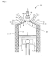
- FIG. 4 illustrates an engine combustion chamber structure according to one embodiment of the heat-insulating film structure.
- the engine combustion chamber structure which is one embodiment of the heat-insulating film structure according to the present invention, includes the heat-insulating films 3 formed on the surfaces of engine constituting members 21 (the substrate 8) constituting the engine combustion chamber 20. Providing the heat-insulating films 3 of the present invention allows improving the heat insulating performance of the engine combustion chamber 20.
- the heat-insulating films 3 are disposed on the surfaces (the inner walls) of the engine constituting members 21 constituting the engine combustion chamber 20. Specifically, there are a top surface 14s of a piston 14, valve heads 16s and 17s of an intake valve 16 and an exhaust valve 17, a bottom surface 13s of a cylinder head 13, and the like.
- the engine 10 is constituted by: a cylinder block 11 where a cylinder 12 is formed; and the cylinder head 13 mounted to cover the top surface of the cylinder block 11. Inside of the cylinder 12 of the cylinder block 11, the piston 14 is provided slidably in the vertical direction.
- a spark plug 15 is mounted on the cylinder head 13. Additionally, the intake valve 16 and the exhaust valve 17 are mounted.
- the intake valve 16 is constituted to open and close an intake passage 18 formed in the cylinder head 13.
- the exhaust valve 17 is constituted to open and close an exhaust passage 19.
- the heat-insulating film 3 is provided on the top surface 14s of the piston 14. Similarly, the heat-insulating films 3 are provided on the valve heads 16s and 17s of the intake valve 16 and the exhaust valve 17 and on the bottom surface 13s of the cylinder head 13. These surfaces are the surfaces forming the engine combustion chamber 20. Providing the heat-insulating films 3 on these surfaces allows improving the heat insulating performance.
- the intake valve 16 opens to supply fuel to the engine combustion chamber 20 surrounded by the cylinder 12, the cylinder head 13, and the piston 14.
- the fuel is burned by ignition of the spark plug 15. This burning pushes down the piston 14.
- the exhaust valve 17 opens to exhaust the exhaust gas generated by the burning.
- the engine 10 (see FIG. 4 ) needs to ensure the heat insulating property of the engine combustion chamber 20 during combustion in a cycle of Air Intake to Burning to Expansion to Air Exhaust. Accordingly, in the case where the heat-insulating film 3 is disposed in the engine combustion chamber 20, it is necessary to set the thickness to an extent that can provide the heat insulating effect. However, when the newly suctioned air during air intake draws the heat accumulated in the heat-insulating film 3 so as to increase the gas temperature, problems such as abnormal combustion might occur. Therefore, the heat-insulating film 3 is preferred to have a small heat capacity while having the thickness to an extent that can provide the heat insulating effect.
- the thickness of the heat-insulating film 3 is more preferred to be within a range of 1 ⁇ m to 5 mm, and further preferred to be within a range of 10 ⁇ m to 1 mm. Setting the thickness of the heat-insulating film 3 in this range allows reducing the occurrence of the problems such as abnormal combustion while ensuring a sufficient heat insulating effect.
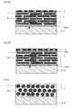
- FIG. 5A illustrates another embodiment of the heat-insulating film structure.
- the embodiment in FIG. 5A is an embodiment of the heat-insulating film structure where a buffer bonding layer 4 (a first buffer bonding layer 4a), the heat-insulating film 3, a dense surface layer 2 are formed on the substrate 8.
- the heat-insulating film structure of the present invention is preferred to include the dense surface layer 2 that contains ceramic and/or glass and has a porosity of 5% or less on the surface of the heat-insulating film 3.
- the dense surface layer 2 that contains ceramic and/or glass and has a porosity of 5% or less on the surface of the heat-insulating film 3.
- the dense surface layer 2 is disposed on the surface of the heat-insulating film 3 and the heat-insulating film 3 is provided in the engine combustion chamber 20
- the dense surface layer 2 reflects the radiation during combustion of fuel in the engine combustion chamber 20 while the dense surface layer 2 radiates heat during exhaust air.
- the heat-insulating film 3 allows reducing heat transfer from the dense surface layer 2 to the engine constituting member 21. Accordingly, the temperature of the inner wall (the wall surface constituting the engine combustion chamber 20) of the engine constituting member 21 is likely to increase while following the gas temperature of the engine combustion chamber 20 during combustion of fuel.
- the heat-insulating film structure of the present invention is preferred to include the buffer bonding layer 4 with a thickness thinner than that of the heat-insulating film 3 between the substrate 8 and the heat-insulating film 3 ( FIG. 5A ) and/or between the heat-insulating film 3 and the dense surface layer 2 (see a second buffer bonding layer 4b in FIG. 5B ). Formation of the heat-insulating film 3 on the substrate 8 and disposing the buffer bonding layer 4 allows reducing the delamination due to the reaction between the substrate 8 and the heat-insulating film 3 and the mismatch between the thermal expansions in case of use at high temperature or the use under the condition that a heat cycle is performed.
- the dense surface layer 2 is a layer that is formed on the surface of the heat-insulating film 3 having a porous structure and that includes more compact ceramic than that of the heat-insulating film 3.
- the porosity is equal to or less than 5%, is preferred to be 0.01 to 4%, and is more preferred to be 0.01 to 3%.
- Such dense layer allows preventing the heat transfer due to the convective flow of the gas (fuel) during combustion of fuel. With the compactness, absorption of fuel and attachment of soot or cinders are less likely to occur.
- the material of the dense surface layer 2 is preferred to be similar to the material of the heat-insulating film 3, and further preferred to have the same composition and a porosity of 5% or less.
- the dense surface layer 2 can be formed of ceramic, and may be, for example, alumina, silica, mullite, silicon nitride, silicon oxynitride, silicon carbide, silicon oxycarbide, titania, zirconia, zinc oxide, glass, and the like.
- the dense surface layer 2 is constituted of the material that reduces the radiation heat transfer from combustion flame as a heat source during combustion of fuel.
- the dense surface layer 2 with the porosity of 5% or less allows reducing the radiation heat transfer to the inner wall constituting the engine combustion chamber 20 immediately after start of combustion to the early stage of combustion. From the later stage of combustion to the exhaust process, when the temperature becomes low, heat is radiated from the dense surface layer 2 to the exhaust gas. This allows preventing the intake gas to be introduced next from heated to a high temperature.
- the dense surface layer 2 is preferred to have a reflectivity larger than 0. 5 at a wavelength of 2 ⁇ m. Providing this reflectivity allows reducing the heat transfer to the heat-insulating film 3.
- the dense surface layer 2 is preferred to have a radiation rate larger than 0.5 at a wavelength of 2.5 ⁇ m. Providing this radiation rate facilitates cooling the heated dense surface layer 2.
- the thickness in a range of 10 nm to 100 ⁇ m is appropriate.
- the heat capacity of the dense surface layer 2 is preferred to be equal to or less than 3000 kJ/(m 3 •K), and more preferred to be equal to or less than 1000 kJ/(m 3 •K).
- the thickness in the above-described range and the low heat capacity in the case where the heat-insulating film 3 and the dense surface layer 2 are provided in the engine combustion chamber 20, the temperature of the inner wall of the engine constituting member 21 is likely to follow the gas temperature inside of the engine combustion chamber 20. Accordingly, the temperature difference between the gas temperature and the dense surface layer 2 decreases. This allows reducing the cooling loss.
- the dense surface layer 2 is preferred to have a thermal conductivity of 3 W/ (m•K) or less. Setting the thermal conductivity in this range allows reducing the heat transfer to the heat-insulating film 3.
- the buffer bonding layer 4 is a layer that is disposed between the substrate 8 (the engine constituting member 21) and the heat-insulating film 3 and/or between the heat-insulating film 3 and the dense surface layer 2 and that has a thickness thinner than that of the heat-insulating film 3.
- the buffer bonding layer 4 allows eliminating the mismatch of the thermal expansions or the Young's moduli between both the layers in contact with this buffer bonding layer 4 so as to reduce the delamination due to thermal stress.
- the buffer bonding layer 4 is preferred to be a material that has an adhesion function or a material that can be formed as a thin film.
- the buffer bonding layer 4 can be, for example, a layer made of an inorganic binder, an inorganic polymer, an oxide sol, liquid glass, a brazing material, a layer formed of a plated film, and the like.
- the buffer bonding layer 4 may be a layer where a material similar to the heat-insulating film 3 is combined with these materials.
- the heat-insulating film 3 formed alone in a thin plate shape can be bonded to the substrate 8 (the engine constituting member 21) and the like by the above-described material, so as to obtain the buffer bonding layer 4.
- the buffer bonding layer 4 is preferred to have a thermal expansion coefficient larger than that of one of the two other layers adjacent to the buffer bonding layer 4 while having a thermal expansion coefficient smaller than that of the other layer.
- the buffer bonding layer 4 is preferred to have a Young's modulus smaller than that of two other layers adjacent to the buffer bonding layer 4. This configuration allows eliminating the mismatch between the layers so as to reduce the delamination due to thermal stress.
- the buffer bonding layer 4 is preferred to have a large thermal resistance, specifically, preferred to have a thermal resistance of 10 -6 m 2 K/W or more. Furthermore, the thermal resistance is preferred to be 10 -6 to 10 m 2 K/W, more preferred to be 10 -5 to 10 m 2 K/W, and further preferred to be 10 -4 to 10 m 2 K/W. Formation of this buffer bonding layer 4 allows ensuring a more sufficient heat insulating effect. Additionally, formation of the buffer bonding layer 4 allows buffering the mismatch between the thermal expansions of the bonded bodies so as to improve the thermal shock resistance and thermal stress resistance.
- the buffer bonding layer 4 is preferred to employ a material composition that reduces the mutual reaction between the respective adjacent layers. This improves the oxidation resistance and the reaction resistance, thus improving the durability of the heat-insulating film 3.
- the following describes a method for manufacturing the heat-insulating film structure (the engine combustion chamber structure).
- the material to be the first buffer bonding layer 4a is applied over (in the case of, for example, an inorganic binder, an inorganic polymer, an oxide sol, liquid glass, or a brazing material) or plated as a film on the engine constituting member 21. Then, the heat-insulating film 3 is formed on the first buffer bonding layer 4a.
- the heat-insulating film 3 can be formed by applying a coating composition over the predetermined substrate 8, drying, and heat treatment.
- the coating composition is obtained by dispersing the porous plate-shaped fillers 1 in a material such as an inorganic binder, an inorganic polymer, an oxide sol, liquid glass, or the like.
- a material such as an inorganic binder, an inorganic polymer, an oxide sol, liquid glass, or the like.
- the second buffer bonding layer 4b is formed on the heat-insulating film 3 similarly to the first buffer bonding layer 4a and the dense surface layer 2 is formed on the second buffer bonding layer 4b.
- the dense surface layer 2 can be formed on the formed heat-insulating film 3 (or on the formed second buffer bonding layer 4b) by a sputtering method, a PVD method, an EB-PVD method, a CVD method, an AD method, thermal spraying, a plasma spray method, a cold spray method, plating, heat treatment after wet coating, and the like.
- a sputtering method a PVD method, an EB-PVD method, a CVD method, an AD method, thermal spraying, a plasma spray method, a cold spray method, plating, heat treatment after wet coating, and the like.
- a base material the first buffer bonding layer 4a or the engine constituting member 21
- a pore former (latex particles or melamine resin particles), polyvinyl butyral resin (PVB) as a binder, DOP as a plasticizer, and xylene and 1-butanol as a solvent were added to yttria partially-stabilized zirconia powders.
- the mixture was mixed with a ball mill for 30 hours so as to prepare a slurry for forming a green sheet.
- a vacuum defoaming treatment was performed on this slurry so as to adjust the viscosity to 4000 cps.
- the doctor blade device the green sheet whose thickness after firing was set to 5 ⁇ m was formed and was cut into an outer shape having dimensions of 50 mm ⁇ 50 mm. This formed body was fired at 1100°C for 1 hour and crushed after the firing so as to obtain a porous and thin plate-shaped filler (porous plate-shaped filler 1).
- This porous plate-shaped filler 1 included pores with pore diameters of 50 nm and had a thickness of 5 ⁇ m or less. When the aspect ratios of 20 random porous plate-shaped fillers were measured, the values of the aspect ratios were 3 to 5. Additionally, the thermal conductivity was 0.3 W/(m•K) and the porosity was 60%.
- a coating composition containing a silica sol, liquid glass, the porous plate-shaped fillers 1, and water was prepared.
- the coating composition was applied over an aluminum alloy as the substrate 8 , dried, and then processed by heat treatment at 500°C, so as to be the heat-insulating film 3.
- the heat-insulating film 3 ten or more of the porous plate-shaped fillers 1 were stacked in the thickness direction and the thickness of the heat-insulating film 3 was approximately 100 ⁇ m.
- the thermal conductivity was 0.8 W/(m•K) and the heat capacity was 1460 kJ/(m 3 •K).
- the porous plate-shaped fillers 1 were manufactured similarly to Example 1.
- a coating composition containing perhydropolysilazane, an amine catalyst, the porous plate-shaped fillers 1, and xylene was prepared.
- the coating composition was applied over an aluminum alloy as the substrate 8, dried, and then processed by heat treatment at 250 °C, so as to be the heat-insulating film 3.
- the heat-insulating film 3 ten or more of the porous plate-shaped fillers 1 were stacked in the thickness direction and the thickness of the heat-insulating film 3 was approximately 100 ⁇ m. Additionally, for the heat-insulating film 3, the thermal conductivity was 0.2 W/(m•K) and the heat capacity was 1150 kJ/(m 3 •K).
- a porous and thin plate-shaped tape was obtained with the procedure similar to that in Example 1 but without coarse crushing. On the surface of this tape, a zinc oxide film was formed by a CVD method. Furthermore, this tape was coarsely crushed so as to obtain the porous plate-shaped fillers 1 having thermal resistance films (coating layers 7) on their surfaces.
- a coating composition containing perhydropolysilazane, an amine catalyst, the above-described porous plate-shaped fillers 1, and xylene was prepared.
- the coating composition was applied over an aluminum alloy as the substrate 8, dried, and then processed by heat treatment at 250°C, so as to be the heat-insulating film 3.
- the heat-insulating film 3 ten or more of the porous plate-shaped fillers 1 were stacked in the thickness direction and the thickness of the heat-insulating film 3 was approximately 100 ⁇ m. Additionally, for the heat-insulating film 3, the thermal conductivity was 0.15 W/(m•K) and the heat capacity was 1180 kJ/(m 3 •K).
- Example 1 Similarly to Example 1, a pore former (latex particles or melamine resin particles), polyvinyl butyral resin (PVB) as a binder, DOP as a plasticizer, and xylene and 1-butanol as a solvent were added to yttria partially- stabilized zirconia powders. The mixture was mixed with a ball mill for 30 hours so as to prepare a slurry for a green sheet. A vacuum defoaming treatment was performed on this slurry so as to adjust the viscosity to 4000 cps. Subsequently, using the doctor blade device, the green sheet whose thickness after firing was set to 5 ⁇ m was formed and was cut into an outer shape having dimensions of 50 mm x 50 mm. This formed body was fired at 1100 °C for 1 hour. The fired body thus obtained was coarsely crushed so as to obtain the porous plate-shaped fillers 1.
- a pore former latex particles or melamine resin particles
- PVB polyvinyl butyral
- the porous plate-shaped filler 1 included pores of 50 nm and had a thickness of 5 ⁇ m or less. When the aspect ratios of 20 random fillers were measured, the values of the aspect ratios were 5 to 10. Additionally, the thermal conductivity was 0.3 W/(m•K).
- a coating composition containing perhydropolysilazane, an amine catalyst, the porous plate-shaped fillers 1, and xylene was prepared.
- the coating composition was applied over an aluminum alloy as the substrate 8, dried, and then processed by heat treatment at 250 °C, so as to be the heat-insulating film 3.
- the thermal conductivity was 0.15 W/ (m•K) and the heat capacity was 1160 kJ/(m 3 •K).
- the porous plate-shaped fillers 1 were manufactured similarly to Example 1.
- a coating composition containing a boehmite fiber sol, the porous plate-shaped filler 1, and water was prepared.
- the coating composition was applied over an aluminum alloy as the substrate 8, dried, and then processed by heat treatment at 500 °C, so as to be the heat-insulating film 3.
- the heat-insulating film 3 ten or more of the porous plate-shaped fillers 1 were stacked in the thickness direction and the thickness of the heat-insulating film 3 was approximately 100 ⁇ m. Additionally, for the heat-insulating film 3, the thermal conductivity was 0.25 W/(m•K) and the heat capacity was 1140 kJ/(m 3 •K).
- the porous plate-shaped fillers 1 were manufactured similarly to Example 1.
- a coating composition containing polysiloxane, the porous plate-shaped fillers 1, isopropyl alcohol was prepared.
- the coating composition was applied over an aluminum alloy as the substrate 8, dried, and then processed by heat treatment at 500°C, so as to be the heat-insulating film 3.
- the thermal conductivity was 0.5 W/(m•K) and the heat capacity was 1490 kJ/(m 3 •K).
- the porous plate-shaped fillers 1 were manufactured similarly to Example 1. However, instead of the yttria partially-stabilized zirconia powders, yttria fully-stabilized zirconia powders were used.
- a coating composition containing polysiloxane, the porous plate-shaped fillers 1, and isopropyl alcohol was prepared.
- the coating composition was applied over an aluminum alloy as the substrate 8, dried, and then processed by heat treatment at 200°C, so as to be the heat-insulating film 3.
- the heat-insulating film 3 ten or more of the porous plate-shaped fillers 1 were stacked in the thickness direction and the thickness of the heat-insulating film 3 was approximately 100 ⁇ m. Additionally, for the heat-insulating film 3, the thermal conductivity was 0.4 W/(m•K) and the heat capacity was 1230 kJ/(m 3 •K).
- the porous plate-shaped fillers 1 were manufactured similarly to Example 7.
- a coating composition containing polysilsesquioxane, the porous plate-shaped fillers 1, and isopropyl alcohol was prepared.
- the coating composition was applied over an aluminum alloy as the substrate 8, dried, and then processed by heat treatment at 200 °C, so as to be the heat-insulating film 3.
- the heat-insulating film 3 ten or more of the porous plate-shaped fillers 1 were stacked in the thickness direction and the thickness of the heat-insulating film 3 was approximately 100 ⁇ m. Additionally, for the heat-insulating film 3, the thermal conductivity was 0.3 W/(m•K) and the heat capacity was 1180 kJ/(m 3 •K).
- the porous plate-shaped fillers 1 were manufactured similarly to Example 7.
- a coating composition containing an acryl-silica hybrid material, the porous plate-shaped fillers 1, and isopropyl alcohol was prepared.
- the coating composition was applied over an aluminum alloy as the substrate 8, dried, and then processed by heat treatment at 200°C, so as to be the heat-insulating film 3.
- the heat-insulating film 3 ten or more of the porous plate-shaped fillers 1 were stacked in the thickness direction and the thickness was approximately 100 ⁇ m. Additionally, for the heat-insulating film 3, the thermal conductivity was 0.3 W/(m•K) and the heat capacity was 1100 kJ/(m 3 •K).
- the porous plate-shaped filler 1 were manufactured similarly to Example 1. However, instead of the yttria partially-stabilized zirconia powders, lanthanum zirconate powders were used.
- a coating composition containing polysiloxane, the porous plate-shaped fillers 1, and isopropyl alcohol was prepared.
- the coating composition was applied over an aluminum alloy as the substrate 8, dried, and then processed by heat treatment at 200°C, so as to be the heat-insulating film 3.
- the heat-insulating film 3 ten or more of the porous plate-shaped fillers 1 were stacked in the thickness direction and the thickness of the heat-insulating film 3 was approximately 100 ⁇ m. Additionally, for the heat-insulating film 3, the thermal conductivity was 0.25 W/(m•K) and the heat capacity was 1050 kJ/(m 3 •K).
- the porous plate-shaped fillers 1 were manufactured similarly to Example 1. However, instead of the yttria partially-stabilized zirconia powders, yttrium silicate powders were used.
- a coating composition containing polysiloxane, the porous plate-shaped fillers 1, and isopropyl alcohol was prepared.
- the coating composition was applied over an aluminum alloy as the substrate 8, dried, and then processed by heat treatment at 200°C, so as to be the heat-insulating film 3.
- the heat-insulating film 3 ten or more of the porous plate-shaped fillers 1 were stacked in the thickness direction and the thickness of the heat-insulating film 3 was approximately 100 ⁇ m. Additionally, for the heat-insulating film 3, the thermal conductivity was 0.3 W/(m•K) and the heat capacity was 1120 kJ/(m 3 •K).
- the porous plate-shaped fillers 1 were manufactured similarly to Example 1. However, instead of the yttria partially-stabilized zirconia powders, strontium niobate powders were used.
- a coating composition containing polysiloxane, the porous plate-shaped fillers 1, and isopropyl alcohol was prepared.
- the coating composition was applied over an aluminum alloy as the substrate 8, dried, and then processed by heat treatment at 200°C, so as to be the heat-insulating film 3.
- the heat-insulating film 3 ten or more of the porous plate-shaped fillers 1 were stacked in the thickness direction and the thickness of the heat-insulating film 3 was approximately 100 ⁇ m. Additionally, for the heat-insulating film 3, the thermal conductivity was 0.25 W/(m•K) and the heat capacity was 1240 kJ/(m 3 •K).
- a pore former (latex particles or melamine resin particles), polyvinyl alcohol (PVA) as a binder, a dispersing agent, and water were added to yttria partially-stabilized zirconia powders to be mixed together by a ball mill for 30 hours, so as to prepare a slurry.
- This slurry was dried by spray drying so as to obtain granules in spherical shapes. These granules were fired at 1100°C for 1 hour. The obtained fired powder was cracked and fine powders were removed so as to obtain spherical fillers 31.
- This spherical filler 31 included pores of 50 nm.
- the spherical filler 31 had an average particle diameter of 20 ⁇ m, the minimum particle diameter of 5 ⁇ m, and a porosity of 60%.
- the values of the aspect ratios were 1 to 1.5.
- the thermal conductivity of the fired body obtained by forming the granules in plate shapes and firing the granules under the same condition was 0.3 W/(m•K).
- FIG. 6 illustrates a heat-insulating film structure of Comparative Example 1.
- the thermal conductivity was 1.7 W/(m•K) and the heat capacity was 1550 kJ/(m 3 •K).
- Comparative Example 1 employed the spherical fillers 31 with the aspect ratios of 1 to 1. 5.
- the thermal conductivity and the heat capacity of the heat-insulating film 3 were increased compared with Examples. That is, the heat-insulating film 3 including the porous plate-shaped fillers 1 allowed reducing the thermal conductivity and the heat capacity compared with the heat-insulating film 3 including the spherical fillers 31.
- the matrix 3m is introduced into these portions or these portions remain as voids.
- the ratio of the matrix 3m (high thermal conducting component) in the heat-insulating film 3 is increased. Accordingly, the thermal conductivity of the heat-insulating film 3 trends to be high. In the case where the portions remain as voids, the thermal conductivity of the heat-insulating film 3 becomes low since the void does not become a heat transfer path.
- the matrix 3m binding between the fillers is in a small amount, and sufficient strength cannot be obtained.
- the fillers are oriented and filled to be stacked. This allows increasing the volume ratio of the fillers without generating unnecessary voids, and ensures wide attached surfaces between the fillers via the matrix 3m even when the matrix 3m introduced between the fillers is in a small amount. Thus, a sufficient strength can be obtained.
- the heat-insulating film and the heat-insulating film structure according to the present invention are applicable to an engine of an automobile and the like, a pipe, a wall of an architectural structure, and the like.
- 1 porous plate-shaped filler
- 2 dense surface layer
- 3 heat-insulating film
- 3m matrix
- 4 buffer bonding layer
- 4a first buffer bonding layer
- 4b second buffer bonding layer
- 7 coating layer
- 8 substrate
- 10 engine
- 11 cylinder block
- 12 cylinder
- 13 cylinder head
- 13s bottom surface (of cylinder head)
- 14 piston
- 14s top surface (of piston)
- 15 spark plug
- 16 intake valve
- 16s valve head
- 17 exhaust valve
- 17s valve head
- 18 intake passage
- 19 exhaust passage
- 20 engine combustion chamber
- 21 engine constituting member
- 31 spherical filler
Landscapes
- Chemical & Material Sciences (AREA)
- Engineering & Computer Science (AREA)
- Organic Chemistry (AREA)
- Materials Engineering (AREA)
- Ceramic Engineering (AREA)
- Chemical Kinetics & Catalysis (AREA)
- Structural Engineering (AREA)
- Manufacturing & Machinery (AREA)
- Wood Science & Technology (AREA)
- Inorganic Chemistry (AREA)
- Life Sciences & Earth Sciences (AREA)
- Physics & Mathematics (AREA)
- Mechanical Engineering (AREA)
- Thermal Sciences (AREA)
- Combustion & Propulsion (AREA)
- Medicinal Chemistry (AREA)
- Polymers & Plastics (AREA)
- Health & Medical Sciences (AREA)
- Acoustics & Sound (AREA)
- General Engineering & Computer Science (AREA)
- Composite Materials (AREA)
- General Chemical & Material Sciences (AREA)
- Metallurgy (AREA)
- Laminated Bodies (AREA)
- Compositions Of Macromolecular Compounds (AREA)
- Paints Or Removers (AREA)
Abstract
Description
- The present invention relates to a heat-insulating film and a heat-insulating film structure for improving a heat insulating effect. The present invention also relates to a porous plate-shaped filler included in a heat-insulating film and a coating composition for forming a heat-insulating film.
- There is a need for a heat-insulating film to be formed on a surface so as to improve heat-insulating efficiency and flame resistance.
Patent Document 1 discloses a coating film that has a high surface hardness and can prevent damage. The coating film is formed by dispersing hollow particles formed of silica shells in a binder. The wear resistance and the high hardness of the hollow particles formed of the silica shells allow improvement in the wear resistance of a substrate where the coating film is formed. The heat insulating property of the hollow particles formed of the silica shells also allows improvement in the flame resistance. -
Patent Document 2 discloses an internal combustion engine that includes a structural member whose heat insulating performance is improved. The internal combustion engine ofPatent Document 2 is constituted such that a heat insulating material is arranged adjacent to the inner wall of an exhaust passage and a high-temperature working gas (exhaust gas) flows along the flow passage formed by the heat insulating material. In the heat insulating material, the respective particles of mesoporous silica spherical (MSS) particles with an average particle diameter of 0.1 to 3 µm are stacked while the particles are densely gathered together via a bonding material. In the MSS particle, countless mesopores with an average pore diameter of 1 to 10 nm are formed. -
- Patent Document 1:
JP-A-2008-200922 - Patent Document 2:
JP-A-2011-52630 - In
Patent Document 1, the hollow particles formed of the silica shells with outer diameters of about 30 to 300 nm are approximately uniformly dispersed in an organic resin binder, an inorganic polymer binder, or an organic-inorganic hybrid binder so as to provide the heat insulating property to the coating film. InPatent Document 2, the mesoporous silica spherical (MSS) particles having the mesopores with the average particle diameter of 0.1 to 3 µm and the average pore diameter of 1 to 10 nm are stacked while being densely gathered together, so as to ensure the high heat insulating performance. - Since the hollow particles and the porous particles used in
Patent Documents FIG. 6 , and the thermal conductivity is not sufficiently low. - An object of the present invention is to provide a heat-insulating film and a heat-insulating film structure with improved heat insulating effects. Additionally, another object is to provide a porous plate-shaped filler included in the heat-insulating film and a coating composition for forming the heat-insulating film.
- The inventors found that it was possible to achieve the above-described objects by using a porous plate-shaped filler that had a plate shape with an aspect ratio of 3 or more, a minimum length of 0.1 to 50 µm, and a porosity of 20 to 99% in the heat-insulating film. That is, the present invention provides the following porous plate-shaped filler, coating composition, heat-insulating film, and heat-insulating film structure.
-
- [1] A porous plate-shaped filler is a plate with an aspect ratio of 3 or more. The porous plate-shaped filler has a minimum length of 0.1 to 50 µm and a porosity of 20 to 99%.
- [2] The porous plate-shaped filler according to [1] described above has a thermal conductivity of 1 W/(m•K) or less.
- [3] The porous plate-shaped filler according to [1] or [2] described above has a heat capacity of 10 to 3000 kJ/(m3•K).
- [4] The porous plate-shaped filler according to any of [1] to [3] described above includes nano-order pores, nano-order particles, or nano-order crystal grains.
- [5] The porous plate-shaped filler according to any of [1] to [4] described above includes pores with a pore diameter of 10 to 500 nm.
- [6] The porous plate-shaped filler according to any of [1] to [5] described above includes a metal oxide.
- [7] In the porous plate-shaped filler according to [6] described above, the metal oxide is an oxide of one element or a composite oxide of two or more elements. The element is selected from the group consisting of Zr, Y, Al, Si, Ti, Nb, Sr, and La.
- [8] The porous plate-shaped filler according to any of [1] to [7] described above includes particles with a particle diameter of 1 nm to 10 µm.
- [9] The porous plate-shaped filler according to any of [1] to [8] described above includes a coating layer with a thickness of 1 nm to 1 µm on at least a part of the surface.
- [10] In the porous plate-shaped filler according to [9] described above, the coating layer is a thermal resistance film that reduces heat transfer and/or reflects radiation heat.
- [11] A coating composition includes: the porous plate-shaped filler according to any of [1] to [10] described above; and one or more of members selected from the group consisting of an inorganic binder, an inorganic polymer, an organic-inorganic hybrid material, an oxide sol, and a liquid glass.
- [12] A heat-insulating film includes: the porous plate-shaped fillers according to any of [1] to [10] described above; and a matrix for binding the porous plate-shaped fillers. The porous plate-shaped fillers are dispersedly arranged in the matrix.
- [13] In the heat-insulating film according to [12] described above, the porous plate-shaped fillers are arranged in a layered state.
- [14] The heat-insulating film according to [12] or [13] described above includes at least one of ceramic, glass, and resin as the matrix.
- [15] In the heat-insulating film according to [14] described above, the matrix is an aggregate of ceramic particulates with particle diameters of 500 nm or less.
- [16] The heat-insulating film according to any of [12] to [15] described above has a thickness of 1 µm to 5 mm.
- [17] The heat-insulating film according to any of [12] to [16] described above has a heat capacity of 1500 kJ/(m3•K) or less.
- [18] The heat-insulating film according to any of [12] to [17] described above has a thermal conductivity of 1.5 W/(m•K) or less.
- [19] A heat-insulating film structure includes the heat-insulating film according to any of [12] to [18] described above. The heat-insulating film is formed on a substrate.
- [20] The heat-insulating film structure according to [19] described above includes a dense surface layer on the surface of the heat-insulating film. The dense surface layer contains ceramic and/or glass and has a porosity of 5% or less.
- [21] The heat-insulating film structure according to [20] described above includes a buffer bonding layer disposed between the substrate and the heat-insulating film and/or between the heat-insulating film and the dense surface layer. The buffer bonding layer has a thickness thinner than a thickness of the heat-insulating film.
- The porous plate-shaped filler has a plate shape with an aspect ratio of 3 or more, a minimum length of 0.1 to 50 µm and a porosity of 20 to 99%. The heat-insulating film using the porous plate-shaped filler ensures a longer length of the heat transfer path compared with the case where a spherical or cubic filler is used. Thus, the thermal conductivity can be reduced. This ensures a higher heat insulating effect than in conventional techniques even when the heat-insulating film is thin. Additionally, the binding area of the porous plate-shaped fillers via the matrix is wider compared with the case where spherical fillers and the like are used. This allows increasing in the strength.
-
-
FIG. 1 is a schematic diagram illustrating one embodiment of a porous plate-shaped filler according to the present invention; -
FIG. 2 is a schematic diagram illustrating another embodiment of the porous plate-shaped filler; -
FIG. 3 is a schematic diagram illustrating one embodiment of a heat-insulating film and a heat-insulating film structure according to the present invention; -
FIG. 4 is a schematic diagram illustrating one embodiment of an engine; -
FIG. 5A is a schematic diagram illustrating another embodiment of the heat-insulating film and the heat-insulating film structure according to the present invention; -
FIG. 5B is a schematic diagram illustrating yet another embodiment of the heat-insulating film and the heat-insulating film structure according to the present invention; and -
FIG. 6 is a schematic diagram illustrating the heat-insulating film and the heat-insulating film structure according to the Comparative Example. - Hereinafter, embodiments of the present invention will be described with reference to the drawings. The present invention is not limited to the following embodiments, and changes, modifications and improvements can be added to the embodiments without departing from the gist of the invention.
-
FIG. 1 illustrates one embodiment of a porous plate-shapedfiller 1 according to the present invention. The porous plate-shapedfiller 1 of the present invention has a plate shape where an aspect ratio is 3 or more, a minimum length of 0.1 to 50 µm, and a porosity of 20 to 99%. In this description, the porosity is obtained by the following formula.
- In the above-described formula, the apparent particle density is measured with a liquid immersion method using mercury. The true density is measured with a pycnometer method after the porous plate-shaped filler is sufficiently pulverized.
- In this description, the aspect ratio is defined by the maximum length/the minimum length of the porous plate-shaped
filler 1. Here, the maximum length is the maximum length of the particle (the porous plate-shaped filler 1) when the particle is sandwiched by a pair of parallel surfaces. The minimum length is similarly the minimum length of the particle when the particle is sandwiched by a pair of parallel surfaces, and corresponds to what is called the thickness in the case of a flat plate shape. The plate shape of the porous plate-shapedfiller 1 of the present invention includes not only a flat plate shape (plate that is flat and not curved) but also a curved plate shape or a plate shape with a non-constant thickness (minimum length) insofar as the aspect ratio is 3 or more and the minimum length is 0.1 to 50 µm. The plate shape may be a fiber-like, needle-like, or block-like shape and the like. Among these shapes, the porous plate-shapedfiller 1 of the present invention is preferred to have a flat plate shape. Additionally, the surface shape of the plate may be any shape of a square shape, a quadrangular shape, a triangular shape, a hexagonal shape, a circular shape, and the like. - This porous plate-shaped
filler 1 included in a heat-insulatingfilm 3 as described later allows improving the heat insulating effect. - The porous plate-shaped
filler 1 is preferred to include nano-order pores, nano-order particles, or crystal grains. Here, the nano order is 1 nm or more and less than 1000 nm. Using the pores, particles, or crystal grains in this range allow improving the heat insulating effect. - The porous plate-shaped
filler 1 of the present invention is preferred to have pores with a pore diameter of 10 to 500 nm. One filler may have one pore (hollow particle) or a large number of pores (porous particle). The hollow particle is a particle where one closed pore is present inside of the particle. The porous particle is a particle where the inside of the particle is porous, that is, a particle that includes pores other than the hollow particle. The porous plate-shapedfiller 1 of the present invention includes not only the porous particle but also the hollow particle. That is, the number of pores included in the porous plate-shapedfiller 1 may be one or a large number, and the pores may be open pores or closed pores. When the porous plate-shapedfiller 1 with these pores is included in the heat-insulatingfilm 3, the pores allow improving the heat insulating effect. - As the material of the porous plate-shaped
filler 1, for example, there are a hollow glass bead, a hollow ceramic bead, a fly ash balloon, a hollow silica, and the like. There are also mesoporous silica, mesoporous titania, mesoporous zirconia, silas balloon, and the like. Alternatively, there is also a porous plate-shaped filler to be obtained by a manufacturing method described later. - The minimum length of the porous plate-shaped
filler 1 is 0.1 to 50 µm, and is preferred to be 10 µm or less. When the minimum length of the porous plate-shapedfiller 1 is short, the heat-insulatingfilm 3 can be thin. That is, the heat insulating effect can be improved even when the heat-insulatingfilm 3 is thin. - The porous plate-shaped
filler 1 of the present invention is preferred to have a thermal conductivity of 1 W/ (m•K) or less. The thermal conductivity is more preferred to be 0.5 W/(m•K) or less, and is further preferred to be 0.3 W/ (m•K) or less. When the porous plate-shapedfiller 1 with this thermal conductivity is included in the heat-insulatingfilm 3, the heat insulating effect can be improved. - The porous plate-shaped
filler 1 is preferred to have a heat capacity of 10 to 3000 kJ/ (m3•K). The heat capacity is more preferred to be 10 to 2500 kJ/(m3•K), and is further preferred to be 10 to 2000 kJ/ (m3•K). When the porous plate-shapedfiller 1 with the heat capacity in this range is included in the heat-insulatingfilm 3, the heat insulating effect can be improved. - The porous plate-shaped
filler 1 is preferably configured to include particles with a particle diameter of 1 nm to 10 µm. The particle may be a particle formed of one crystal grain (single crystal particle), or may be a particle formed of multiple crystal grains (polycrystalline particle). That is, the porous plate-shapedfiller 1 is preferred to be a group of particles with particle diameters in this range. The particle diameter is obtained by measuring the size of one particle (diameter in the case of a spherical shape, otherwise the largest diameter) among the particle group constituting the frame of the porous plate-shapedfiller 1 from an image by electron microscope observation. The particle diameter is preferred to be 1 nm to 5 µm, and is further preferred to be 1 nm to 1 µm. When the porous plate-shapedfiller 1 with the heat capacity in this range is included in the heat-insulatingfilm 3, the heat insulating effect can be improved. - The porous plate-shaped
filler 1 is preferred to include metal oxides, and is further preferred to be formed only of metal oxides alone. This is because the inclusion of the metal oxides is likely to cause a low thermal conductivity due to a strong ion binding property between metal and oxygen compared with the metal non-oxides (such as carbides and nitrides). - In the porous plate-shaped
filler 1, the metal oxide is preferred to be an oxide of one element selected from the group consisting of Zr, Y, Al, Si, Ti, Nb, Sr, and La or to be a composite oxide of two or more elements. This is because thermal conduction due to a lattice vibration (phonon) which is the main cause of the thermal conduction is less likely to occur when the metal oxides are the oxides or the composite oxides of these elements. - As illustrated in
FIG. 2 , the porous plate-shapedfiller 1 of the present invention is preferred to have acoating layer 7 with a thickness of 1 nm to 1 µm on at least a part of the surface of the porous plate-shapedfiller 1. Further, thecoating layer 7 is preferred to be a thermal resistance film that reduces the heat transfer and/or reflects the radiation heat and/or scatters the lattice vibration (phonon). When a thermal resistance film with several tens nm is formed on the surface of the porous plate-shapedfiller 1, the thermal conductivity of the heat-insulatingfilm 3 can be further decreased. Thus, such configuration is preferable. The thermal resistance film should not be of the same material as that of the porous plate-shaped filler to be coated, and the porous plate-shapedfiller 1 is preferred to be coated with a different material (such as alumina and zinc oxide). While there is no problem whether the thermal resistance film is fine or porous, the thermal resistance film is preferred to be fine. The formation of the thermal resistance film on a part of the surface of the porous plate-shaped filler provides the effect that the thermal conductivity is decreased. When all of the surface of the porous plate-shapedfiller 1 is covered with the thermal resistance film, the effect that the thermal conductivity is further decreased can be obtained. - Next a method for manufacturing the porous plate-shaped
filler 1 of the present invention is described. As the method for manufacturing the porous plate-shapedfiller 1, there are press molding, casting, extrusion, injection molding, tape casting, a doctor blade method, and the like. Any method is possible, however the doctor blade method as an example is described in the following. - Firstly, a pore former, a binder, a plasticizer, a solvent, and the like are added to ceramic powders to be mixed together by a ball mill and the like, so as to prepare a slurry for forming a green sheet.
- As the ceramic powders there can be used zirconia powders, partially-stabilized zirconia powders (such as yttria partially-stabilized zirconia powders), fully-stabilized zirconia powders (such as yttria fully-stabilized zirconia powders), alumina powders, silica powders, titania powders, oxidized lanthanum powders, yttria powders, rare-earth zirconate powders (such as lanthanum zirconate powders), rare-earth silicate powders (such as yttrium silicate powders), niobate powders (such as strontium niobate powders), mullite powders, spinel powders, zircon particles, magnesia powders, yttria powders, ceria powders, silicon carbide powders, silicon nitride powders, aluminum nitride powders, and the like. Regarding these powders, not only one kind but also the combination of two or more kinds may be used. Additionally, the powders are not limited to dry powders, and may employ powders dispersed in water or an organic solvent in a colloidal state (sol state). As the pore former there can be used latex particles, melamine resin particles, PMMA particles, polyethylene particles, polystyrene particles, carbon black particles, foamable resin, water absorbable resin, and the like. As the binder there can be used polyvinyl butyral resin (PVB), polyvinyl alcohol resin, polyvinyl acetate resin, polyacrylic resin, and the like. As the plasticizer there can be used dibutyl phthalate (DBP), dioctyl phthalate (DOP), and the like. As the solvent there can be used xylene, 1-butanol, and the like.
- The above-described slurry for forming the green sheet undergoes a vacuum defoaming treatment to adjust the viscosity to be 100 to 10000 cps. Subsequently, using a doctor blade device, the green sheet is formed such that the thickness after firing is 0.1 to 100 µm, and is cut into the outer shape of dimensions (0.5 to 200) mm × (0.5 to 200) mm. The cut formed body is fired at 800 to 2300 °C for 0.5 to 20 hours and is crushed as necessary after the firing. Thus, a porous and thin plate filler (the porous plate-shaped filler 1) can be obtained. Here, the green sheet before firing can be processed, for example, cut or punched into a predetermined surface shape (a square shape, a quadrangular shape, a hexagonal shape, or a circular shape) and then fired, so as to obtain the porous and thin plate filler without crushing after firing.
- The coating composition of the present invention includes the above-described porous plate-shaped
filler 1 and one or more selected from the group consisting of an inorganic binder, an inorganic polymer, an organic-inorganic hybrid material, an oxide sol, and liquid glass. Furthermore, the coating composition may include a compact filler, a viscosity adjuster, a solvent, a dispersing agent, and the like. The heat-insulatingfilm 3 can be formed by application, drying, and/or heat treatment of the coating composition. The specific materials included in the coating composition are cement, bentonite, aluminum phosphate, silica sol, alumina sol, boehmite sol, zirconia sol, titania sol, tetramethyl orthosilicate, tetraethyl orthosilicate, polysilazane, polycarbosilane, polyvinyl silane, polymethylsilane, polysiloxane, polysilsesquioxane, silicone, geopolymer, sodium silicate, and the like. The organic-inorganic hybrid material is preferred to be an acryl-silica hybrid material, an epoxy-silica hybrid material, a phenol-silica hybrid material, a polycarbonate - silica hybrid material, a nylon-silica hybrid material, a nylon-cray hybrid material, an acryl-alumina hybrid material, an acryl-calcium silicate hydrate hybrid material, and the like. - The viscosity of the coating composition is preferably to be 0.1 to 5000 mPa•s, and is further preferably to be 0.5 to 1000 mPa•s. In the case where the viscosity is smaller than 0.1 mPa•s, the coating composition might flow after the application and the thickness of the coated film might be inhomogeneous. In the case where the viscosity is larger than 5000 mPa•s, the coating composition might be non-flowable and less likely to be homogeneously applied.
- The heat-insulating
film 3 will be described usingFIG. 3 . In the heat-insulatingfilm 3 of the present invention, the above-described porous plate-shapedfillers 1 are dispersedly arranged in amatrix 3m for binding the porous plate-shapedfillers 1 together. Thematrix 3m is a component that is present in the peripheral area of the porous plate-shapedfiller 1 and between these particles, and is a component for binding these particles together. - The heat-insulating
film 3 of the present invention is preferred to have the porous plate-shapedfillers 1 arranged (stacked) in a layered state. Here, the arrangement in the layered state means that the multiple porous plate-shapedfillers 1 are present in thematrix 3m in an oriented state where the direction of the minimum length of the porous plate-shapedfiller 1 corresponds to the direction parallel to the thickness direction of the heat-insulatingfilm 3. Here, it is to be noted that the positions (the positions of the center of gravity) of the porous plate-shapedfillers 1 need not be orderly and periodically arranged in the X, Y, and Z directions (here, the Z direction is defined as the thickness direction) of the heat-insulatingfilm 3, and there is no problem if the positions of the porous plate-shapedfillers 1 are present randomly. While there is no problem if the number of stacked fillers is equal to or more than 1, the number of stacked fillers is preferably larger and preferably equal to or more than 5. Stacking the porous plate-shapedfillers 1 in the layered state in the heat-insulatingfilm 3 ensures a long folded heat transfer path so as to improve the heat insulating effect. In particular, as illustrated inFIG. 3 , the positions of the porous plate-shapedfillers 1 are preferred not to be orderly arranged in the Z direction (displaced from one another) since the heat transfer path is folded more to be longer. - The heat-insulating
film 3 of the present invention is preferred to include at least one of ceramic, glass, and resin as thematrix 3m. From the standpoint of thermal resistance, ceramic or glass is more preferred. More specifically, as the material to be thematrix 3m, there are, for example, silica, alumina, mullite, zirconia, titania, silicon nitride, silicon oxynitride, silicon carbide, silicon oxycarbide, calcium silicate, calcium aluminate, calcium aluminosilicate, aluminum phosphate, potassium aluminosilicate, glass, and the like. From the standpoint of thermal conductivity, these are preferred to be amorphous materials. Alternatively, in the case where the material of thematrix 3m is ceramic, aggregates of particulates with particle diameters of 500 nm or less are preferred. Using the aggregates of the particulates with particle diameters of 500 nm or less as thematrix 3m allows further reducing the thermal conductivity. In the case where the material to be thematrix 3m is resin, there can be used silicone resin, polyimide resin, polyamide resin, acrylic resin, epoxy resin, and the like. - As illustrated in
FIG. 3 , the portion of thematrix 3m with a high thermal conductivity becomes a main heat transfer path. The heat-insulatingfilm 3 of the present invention includes the porous plate-shapedfillers 1, and the heat transfer path has many detours with respect to the direction (the thickness direction of the film) along which heat transfer is unwanted. That is, since the length of the heat transfer path becomes long, the thermal conductivity can be decreased. The binding area of the porous plate-shapedfillers 1 via thematrix 3m is wider than that of spherical fillers 31 (seeFIG. 6 ). Accordingly, the strength of the entire heat-insulating film is increased. Thus, erosion, delamination, and the like are less likely to occur. - In the heat-insulating
film 3, it is preferred that, the porosity of the entire heat-insulatingfilm 3 be 10 to 99%, the porosity of the porous plate-shapedfiller 1 be 20 to 99%, and the porosity of thematrix 3m be 0 to 70%. - The heat-insulating
film 3 of the present invention is preferred to have a thickness of 1 µm to 5 mm. Setting this thickness allows providing a heat insulating effect without providing a negative effect on the characteristics of a substrate 8 coated with the heat-insulatingfilm 3. Here, the thickness of the heat-insulatingfilm 3 can be selected within the above-described range as necessary corresponding to the usage of the heat-insulatingfilm 3. - For the heat-insulating
film 3 of the present invention, the heat capacity is preferred to be equal to or less than 1500 kJ/ (m3•K), more preferred to be equal to or less than 1000 kJ/(m3•K), and most preferred to be equal to or less than 500 kJ/(m3•K). When the heat capacity is low, for example, in the case where the heat-insulatingfilm 3 is formed in an engine combustion chamber 20 (seeFIG. 4 ), the gas temperature within theengine combustion chamber 20 is likely to be reduced after exhausting fuel. This allows reducing the problems such as abnormal combustion of anengine 10. - For the heat-insulating
film 3 of the present invention, the thermal conductivity is preferred to be equal to or less than 1.5 W/(m•K). For the heat-insulatingfilm 3, the thermal conductivity is more preferred to be equal to or less than 1 W/(m•K), and most preferred to be equal to or less than 0.5 W/(m•K). Setting a low thermal conductivity allows reducing the heat transfer. - The heat-insulating
film 3 can be formed by applying the above-described coating composition over the substrate 8 and drying. After the drying, heat treatment may be performed to form the heat-insulatingfilm 3. Here, repeating application and drying or heat treatment allows forming a thick heat-insulatingfilm 3. Alternatively, it is possible to form the heat-insulatingfilm 3 on a temporary substrate and then remove the temporary substrate to manufacture the heat-insulatingfilm 3 in a thin plate shape alone separately, so as to attach or bond this heat-insulatingfilm 3 to the substrate 8. As the substrate 8 there can be used metal, ceramic, glass, plastic, wood, cloth, paper, and the like. In particular, examples wherein the substrate 8 is metal include iron, iron alloy, stainless steel, aluminum, aluminum alloy, nickel alloy, cobalt alloy, tungsten alloy, copper alloy, and the like. - The heat-insulating film structure of the present invention will be described using
FIG. 3 andFIG. 4 . As illustrated inFIG. 3 , the heat-insulating film structure of the present invention is a heat-insulating film structure where the above-described heat-insulatingfilm 3 is formed on the substrate 8. Further,FIG. 4 illustrates an engine combustion chamber structure according to one embodiment of the heat-insulating film structure. - As illustrated in
FIG. 4 , the engine combustion chamber structure, which is one embodiment of the heat-insulating film structure according to the present invention, includes the heat-insulatingfilms 3 formed on the surfaces of engine constituting members 21 (the substrate 8) constituting theengine combustion chamber 20. Providing the heat-insulatingfilms 3 of the present invention allows improving the heat insulating performance of theengine combustion chamber 20. - The heat-insulating
films 3 are disposed on the surfaces (the inner walls) of the engine constituting members 21 constituting theengine combustion chamber 20. Specifically, there are atop surface 14s of a piston 14, valve heads 16s and 17s of an intake valve 16 and an exhaust valve 17, a bottom surface 13s of a cylinder head 13, and the like. - The
engine 10 is constituted by: a cylinder block 11 where acylinder 12 is formed; and the cylinder head 13 mounted to cover the top surface of the cylinder block 11. Inside of thecylinder 12 of the cylinder block 11, the piston 14 is provided slidably in the vertical direction. - On the cylinder head 13, a
spark plug 15 is mounted. Additionally, the intake valve 16 and the exhaust valve 17 are mounted. The intake valve 16 is constituted to open and close anintake passage 18 formed in the cylinder head 13. The exhaust valve 17 is constituted to open and close an exhaust passage 19. - As illustrated in
FIG. 4 , the heat-insulatingfilm 3 is provided on thetop surface 14s of the piston 14. Similarly, the heat-insulatingfilms 3 are provided on the valve heads 16s and 17s of the intake valve 16 and the exhaust valve 17 and on the bottom surface 13s of the cylinder head 13. These surfaces are the surfaces forming theengine combustion chamber 20. Providing the heat-insulatingfilms 3 on these surfaces allows improving the heat insulating performance. - The intake valve 16 opens to supply fuel to the
engine combustion chamber 20 surrounded by thecylinder 12, the cylinder head 13, and the piston 14. The fuel is burned by ignition of thespark plug 15. This burning pushes down the piston 14. The exhaust valve 17 opens to exhaust the exhaust gas generated by the burning. - The engine 10 (see
FIG. 4 ) needs to ensure the heat insulating property of theengine combustion chamber 20 during combustion in a cycle of Air Intake to Burning to Expansion to Air Exhaust. Accordingly, in the case where the heat-insulatingfilm 3 is disposed in theengine combustion chamber 20, it is necessary to set the thickness to an extent that can provide the heat insulating effect. However, when the newly suctioned air during air intake draws the heat accumulated in the heat-insulatingfilm 3 so as to increase the gas temperature, problems such as abnormal combustion might occur. Therefore, the heat-insulatingfilm 3 is preferred to have a small heat capacity while having the thickness to an extent that can provide the heat insulating effect. Accordingly, the thickness of the heat-insulatingfilm 3 is more preferred to be within a range of 1 µm to 5 mm, and further preferred to be within a range of 10 µm to 1 mm. Setting the thickness of the heat-insulatingfilm 3 in this range allows reducing the occurrence of the problems such as abnormal combustion while ensuring a sufficient heat insulating effect. -
FIG. 5A illustrates another embodiment of the heat-insulating film structure. The embodiment inFIG. 5A is an embodiment of the heat-insulating film structure where a buffer bonding layer 4 (a firstbuffer bonding layer 4a), the heat-insulatingfilm 3, adense surface layer 2 are formed on the substrate 8. - As illustrated in
FIG. 5A , the heat-insulating film structure of the present invention is preferred to include thedense surface layer 2 that contains ceramic and/or glass and has a porosity of 5% or less on the surface of the heat-insulatingfilm 3. In the case where the heat-insulatingfilm 3 is formed on the inner surface of the combustion chamber or the pipe in the engine of an automobile and the like, formation of thedense surface layer 2 on the outermost surface of the heat-insulatingfilm 3 allows preventing absorption of fuel and attachment of cinders. - Furthermore, in the case where the
dense surface layer 2 is disposed on the surface of the heat-insulatingfilm 3 and the heat-insulatingfilm 3 is provided in theengine combustion chamber 20, thedense surface layer 2 reflects the radiation during combustion of fuel in theengine combustion chamber 20 while thedense surface layer 2 radiates heat during exhaust air. The heat-insulatingfilm 3 allows reducing heat transfer from thedense surface layer 2 to the engine constituting member 21. Accordingly, the temperature of the inner wall (the wall surface constituting the engine combustion chamber 20) of the engine constituting member 21 is likely to increase while following the gas temperature of theengine combustion chamber 20 during combustion of fuel. - The heat-insulating film structure of the present invention is preferred to include the
buffer bonding layer 4 with a thickness thinner than that of the heat-insulatingfilm 3 between the substrate 8 and the heat-insulating film 3 (FIG. 5A ) and/or between the heat-insulatingfilm 3 and the dense surface layer 2 (see a secondbuffer bonding layer 4b inFIG. 5B ). Formation of the heat-insulatingfilm 3 on the substrate 8 and disposing thebuffer bonding layer 4 allows reducing the delamination due to the reaction between the substrate 8 and the heat-insulatingfilm 3 and the mismatch between the thermal expansions in case of use at high temperature or the use under the condition that a heat cycle is performed. - The following describes the
dense surface layer 2 and thebuffer bonding layer 4 in detail. - The
dense surface layer 2 is a layer that is formed on the surface of the heat-insulatingfilm 3 having a porous structure and that includes more compact ceramic than that of the heat-insulatingfilm 3. For thedense surface layer 2, the porosity is equal to or less than 5%, is preferred to be 0.01 to 4%, and is more preferred to be 0.01 to 3%. Such dense layer allows preventing the heat transfer due to the convective flow of the gas (fuel) during combustion of fuel. With the compactness, absorption of fuel and attachment of soot or cinders are less likely to occur. - The material of the
dense surface layer 2 is preferred to be similar to the material of the heat-insulatingfilm 3, and further preferred to have the same composition and a porosity of 5% or less. Thedense surface layer 2 can be formed of ceramic, and may be, for example, alumina, silica, mullite, silicon nitride, silicon oxynitride, silicon carbide, silicon oxycarbide, titania, zirconia, zinc oxide, glass, and the like. - The
dense surface layer 2 is constituted of the material that reduces the radiation heat transfer from combustion flame as a heat source during combustion of fuel. Thedense surface layer 2 is preferred to easily radiate its own heat when the fuel is exhausted. Accordingly, it is preferred to control the reflectivity and the radiation rate in the wavelength range expected from Wien's displacement law (λmT=2898 [µm•K] : here, Am denotes the wavelength indicative of the maximum radiation intensity and T denotes the temperature). That is, the reflectivity is preferred to be large at a wavelength smaller than 2 µm and the radiation rate is preferred to be large at a wavelength larger than 2 µm. - The
dense surface layer 2 with the porosity of 5% or less allows reducing the radiation heat transfer to the inner wall constituting theengine combustion chamber 20 immediately after start of combustion to the early stage of combustion. From the later stage of combustion to the exhaust process, when the temperature becomes low, heat is radiated from thedense surface layer 2 to the exhaust gas. This allows preventing the intake gas to be introduced next from heated to a high temperature. - The
dense surface layer 2 is preferred to have a reflectivity larger than 0. 5 at a wavelength of 2 µm. Providing this reflectivity allows reducing the heat transfer to the heat-insulatingfilm 3. - The
dense surface layer 2 is preferred to have a radiation rate larger than 0.5 at a wavelength of 2.5 µm. Providing this radiation rate facilitates cooling the heateddense surface layer 2. - While the
dense surface layer 2 is preferred to be thinner, the thickness in a range of 10 nm to 100 µm is appropriate. The heat capacity of thedense surface layer 2 is preferred to be equal to or less than 3000 kJ/(m3•K), and more preferred to be equal to or less than 1000 kJ/(m3•K). According to the thickness in the above-described range and the low heat capacity (thin film and small volume), in the case where the heat-insulatingfilm 3 and thedense surface layer 2 are provided in theengine combustion chamber 20, the temperature of the inner wall of the engine constituting member 21 is likely to follow the gas temperature inside of theengine combustion chamber 20. Accordingly, the temperature difference between the gas temperature and thedense surface layer 2 decreases. This allows reducing the cooling loss. - The
dense surface layer 2 is preferred to have a thermal conductivity of 3 W/ (m•K) or less. Setting the thermal conductivity in this range allows reducing the heat transfer to the heat-insulatingfilm 3. - The
buffer bonding layer 4 is a layer that is disposed between the substrate 8 (the engine constituting member 21) and the heat-insulatingfilm 3 and/or between the heat-insulatingfilm 3 and thedense surface layer 2 and that has a thickness thinner than that of the heat-insulatingfilm 3. Thebuffer bonding layer 4 allows eliminating the mismatch of the thermal expansions or the Young's moduli between both the layers in contact with thisbuffer bonding layer 4 so as to reduce the delamination due to thermal stress. - The
buffer bonding layer 4 is preferred to be a material that has an adhesion function or a material that can be formed as a thin film. For example, thebuffer bonding layer 4 can be, for example, a layer made of an inorganic binder, an inorganic polymer, an oxide sol, liquid glass, a brazing material, a layer formed of a plated film, and the like. Alternatively, thebuffer bonding layer 4 may be a layer where a material similar to the heat-insulatingfilm 3 is combined with these materials. Alternatively, the heat-insulatingfilm 3 formed alone in a thin plate shape can be bonded to the substrate 8 (the engine constituting member 21) and the like by the above-described material, so as to obtain thebuffer bonding layer 4. - The
buffer bonding layer 4 is preferred to have a thermal expansion coefficient larger than that of one of the two other layers adjacent to thebuffer bonding layer 4 while having a thermal expansion coefficient smaller than that of the other layer. Thebuffer bonding layer 4 is preferred to have a Young's modulus smaller than that of two other layers adjacent to thebuffer bonding layer 4. This configuration allows eliminating the mismatch between the layers so as to reduce the delamination due to thermal stress. - The
buffer bonding layer 4 is preferred to have a large thermal resistance, specifically, preferred to have a thermal resistance of 10-6 m2K/W or more. Furthermore, the thermal resistance is preferred to be 10-6 to 10 m2K/W, more preferred to be 10-5 to 10 m2K/W, and further preferred to be 10-4 to 10 m2K/W. Formation of thisbuffer bonding layer 4 allows ensuring a more sufficient heat insulating effect. Additionally, formation of thebuffer bonding layer 4 allows buffering the mismatch between the thermal expansions of the bonded bodies so as to improve the thermal shock resistance and thermal stress resistance. - Furthermore, the
buffer bonding layer 4 is preferred to employ a material composition that reduces the mutual reaction between the respective adjacent layers. This improves the oxidation resistance and the reaction resistance, thus improving the durability of the heat-insulatingfilm 3. - The following describes a method for manufacturing the heat-insulating film structure (the engine combustion chamber structure).
- In the case of the configuration that has the first
buffer bonding layer 4a between the inner wall (the engine constituting member 21) constituting theengine combustion chamber 20 and the heat-insulatingfilm 3, the material to be the firstbuffer bonding layer 4a is applied over (in the case of, for example, an inorganic binder, an inorganic polymer, an oxide sol, liquid glass, or a brazing material) or plated as a film on the engine constituting member 21. Then, the heat-insulatingfilm 3 is formed on the firstbuffer bonding layer 4a. - The heat-insulating
film 3 can be formed by applying a coating composition over the predetermined substrate 8, drying, and heat treatment. The coating composition is obtained by dispersing the porous plate-shapedfillers 1 in a material such as an inorganic binder, an inorganic polymer, an oxide sol, liquid glass, or the like. Alternatively, it is possible to separately manufacture a porous thin plate and attach this to the engine constituting member 21 with a material forming the firstbuffer bonding layer 4a as a binding material. - In the case of the configuration that has the second
buffer bonding layer 4b between the heat-insulatingfilm 3 and thedense surface layer 2, the secondbuffer bonding layer 4b is formed on the heat-insulatingfilm 3 similarly to the firstbuffer bonding layer 4a and thedense surface layer 2 is formed on the secondbuffer bonding layer 4b. - The
dense surface layer 2 can be formed on the formed heat-insulating film 3 (or on the formed secondbuffer bonding layer 4b) by a sputtering method, a PVD method, an EB-PVD method, a CVD method, an AD method, thermal spraying, a plasma spray method, a cold spray method, plating, heat treatment after wet coating, and the like. Alternatively, it is possible to form by separately manufacturing a compact and thin plate as thedense surface layer 2 to be bound with a base material (the firstbuffer bonding layer 4a or the engine constituting member 21) using the material forming the heat-insulatingfilm 3 as the binding material. Alternatively, it is also possible to form by separately manufacturing a compact and thin plate as thedense surface layer 2 to be bound with the heat-insulatingfilm 3 by the secondbuffer bonding layer 4b. - The following describes the present invention based on Examples further in detail. The present invention is not limited to these examples.
- Firstly, a pore former (latex particles or melamine resin particles), polyvinyl butyral resin (PVB) as a binder, DOP as a plasticizer, and xylene and 1-butanol as a solvent were added to yttria partially-stabilized zirconia powders. The mixture was mixed with a ball mill for 30 hours so as to prepare a slurry for forming a green sheet. A vacuum defoaming treatment was performed on this slurry so as to adjust the viscosity to 4000 cps. Subsequently, using the doctor blade device, the green sheet whose thickness after firing was set to 5 µm was formed and was cut into an outer shape having dimensions of 50 mm × 50 mm. This formed body was fired at 1100°C for 1 hour and crushed after the firing so as to obtain a porous and thin plate-shaped filler (porous plate-shaped filler 1).
- This porous plate-shaped
filler 1 included pores with pore diameters of 50 nm and had a thickness of 5 µm or less. When the aspect ratios of 20 random porous plate-shaped fillers were measured, the values of the aspect ratios were 3 to 5. Additionally, the thermal conductivity was 0.3 W/(m•K) and the porosity was 60%. - Subsequently, a coating composition containing a silica sol, liquid glass, the porous plate-shaped
fillers 1, and water was prepared. The coating composition was applied over an aluminum alloy as the substrate 8 , dried, and then processed by heat treatment at 500°C, so as to be the heat-insulatingfilm 3. Here, in the heat-insulatingfilm 3, ten or more of the porous plate-shapedfillers 1 were stacked in the thickness direction and the thickness of the heat-insulatingfilm 3 was approximately 100 µm. Additionally, for the heat-insulatingfilm 3, the thermal conductivity was 0.8 W/(m•K) and the heat capacity was 1460 kJ/(m3•K). - The porous plate-shaped
fillers 1 were manufactured similarly to Example 1. - Subsequently, a coating composition containing perhydropolysilazane, an amine catalyst, the porous plate-shaped
fillers 1, and xylene was prepared. The coating composition was applied over an aluminum alloy as the substrate 8, dried, and then processed by heat treatment at 250 °C, so as to be the heat-insulatingfilm 3. - Here, in the heat-insulating
film 3, ten or more of the porous plate-shapedfillers 1 were stacked in the thickness direction and the thickness of the heat-insulatingfilm 3 was approximately 100 µm. Additionally, for the heat-insulatingfilm 3, the thermal conductivity was 0.2 W/(m•K) and the heat capacity was 1150 kJ/(m3•K). - A porous and thin plate-shaped tape was obtained with the procedure similar to that in Example 1 but without coarse crushing. On the surface of this tape, a zinc oxide film was formed by a CVD method. Furthermore, this tape was coarsely crushed so as to obtain the porous plate-shaped
fillers 1 having thermal resistance films (coating layers 7) on their surfaces. - Subsequently, a coating composition containing perhydropolysilazane, an amine catalyst, the above-described porous plate-shaped
fillers 1, and xylene was prepared. The coating composition was applied over an aluminum alloy as the substrate 8, dried, and then processed by heat treatment at 250°C, so as to be the heat-insulatingfilm 3. - Here, in the heat-insulating
film 3, ten or more of the porous plate-shapedfillers 1 were stacked in the thickness direction and the thickness of the heat-insulatingfilm 3 was approximately 100 µm. Additionally, for the heat-insulatingfilm 3, the thermal conductivity was 0.15 W/(m•K) and the heat capacity was 1180 kJ/(m3•K). - Similarly to Example 1, a pore former (latex particles or melamine resin particles), polyvinyl butyral resin (PVB) as a binder, DOP as a plasticizer, and xylene and 1-butanol as a solvent were added to yttria partially- stabilized zirconia powders. The mixture was mixed with a ball mill for 30 hours so as to prepare a slurry for a green sheet. A vacuum defoaming treatment was performed on this slurry so as to adjust the viscosity to 4000 cps. Subsequently, using the doctor blade device, the green sheet whose thickness after firing was set to 5 µm was formed and was cut into an outer shape having dimensions of 50 mm x 50 mm. This formed body was fired at 1100 °C for 1 hour. The fired body thus obtained was coarsely crushed so as to obtain the porous plate-shaped
fillers 1. - The porous plate-shaped
filler 1 included pores of 50 nm and had a thickness of 5 µm or less. When the aspect ratios of 20 random fillers were measured, the values of the aspect ratios were 5 to 10. Additionally, the thermal conductivity was 0.3 W/(m•K). - Subsequently, a coating composition containing perhydropolysilazane, an amine catalyst, the porous plate-shaped
fillers 1, and xylene was prepared. The coating composition was applied over an aluminum alloy as the substrate 8, dried, and then processed by heat treatment at 250 °C, so as to be the heat-insulatingfilm 3. - At this time, in the heat-insulating
film 3, ten or more of the porous plate-shapedfillers 1 were stacked in the thickness direction and the thickness of the heat-insulatingfilm 3 was approximately 100 µm. Additionally, for the heat-insulatingfilm 3, the thermal conductivity was 0.15 W/ (m•K) and the heat capacity was 1160 kJ/(m3•K). - The porous plate-shaped
fillers 1 were manufactured similarly to Example 1. - Subsequently, a coating composition containing a boehmite fiber sol, the porous plate-shaped
filler 1, and water was prepared. The coating composition was applied over an aluminum alloy as the substrate 8, dried, and then processed by heat treatment at 500 °C, so as to be the heat-insulatingfilm 3. - Here, in the heat-insulating
film 3, ten or more of the porous plate-shapedfillers 1 were stacked in the thickness direction and the thickness of the heat-insulatingfilm 3 was approximately 100 µm. Additionally, for the heat-insulatingfilm 3, the thermal conductivity was 0.25 W/(m•K) and the heat capacity was 1140 kJ/(m3•K). - The porous plate-shaped
fillers 1 were manufactured similarly to Example 1. - Subsequently, a coating composition containing polysiloxane, the porous plate-shaped
fillers 1, isopropyl alcohol was prepared. The coating composition was applied over an aluminum alloy as the substrate 8, dried, and then processed by heat treatment at 500°C, so as to be the heat-insulatingfilm 3. - Here, in the heat-insulating
film 3, ten or more of the porous plate-shapedfillers 1 were stacked in the thickness direction and the thickness of the heat-insulatingfilm 3 was approximately 100 µm. Additionally, for the heat-insulatingfilm 3, the thermal conductivity was 0.5 W/(m•K) and the heat capacity was 1490 kJ/(m3•K). - The porous plate-shaped
fillers 1 were manufactured similarly to Example 1. However, instead of the yttria partially-stabilized zirconia powders, yttria fully-stabilized zirconia powders were used. - Subsequently, a coating composition containing polysiloxane, the porous plate-shaped
fillers 1, and isopropyl alcohol was prepared. The coating composition was applied over an aluminum alloy as the substrate 8, dried, and then processed by heat treatment at 200°C, so as to be the heat-insulatingfilm 3. - Here, in the heat-insulating
film 3, ten or more of the porous plate-shapedfillers 1 were stacked in the thickness direction and the thickness of the heat-insulatingfilm 3 was approximately 100 µm. Additionally, for the heat-insulatingfilm 3, the thermal conductivity was 0.4 W/(m•K) and the heat capacity was 1230 kJ/(m3•K). - The porous plate-shaped
fillers 1 were manufactured similarly to Example 7. - Subsequently, a coating composition containing polysilsesquioxane, the porous plate-shaped
fillers 1, and isopropyl alcohol was prepared. The coating composition was applied over an aluminum alloy as the substrate 8, dried, and then processed by heat treatment at 200 °C, so as to be the heat-insulatingfilm 3. - Here, in the heat-insulating
film 3, ten or more of the porous plate-shapedfillers 1 were stacked in the thickness direction and the thickness of the heat-insulatingfilm 3 was approximately 100 µm. Additionally, for the heat-insulatingfilm 3, the thermal conductivity was 0.3 W/(m•K) and the heat capacity was 1180 kJ/(m3•K). - The porous plate-shaped
fillers 1 were manufactured similarly to Example 7. - Subsequently, a coating composition containing an acryl-silica hybrid material, the porous plate-shaped
fillers 1, and isopropyl alcohol was prepared. The coating composition was applied over an aluminum alloy as the substrate 8, dried, and then processed by heat treatment at 200°C, so as to be the heat-insulatingfilm 3. - Here, in the heat-insulating
film 3, ten or more of the porous plate-shapedfillers 1 were stacked in the thickness direction and the thickness was approximately 100 µm. Additionally, for the heat-insulatingfilm 3, the thermal conductivity was 0.3 W/(m•K) and the heat capacity was 1100 kJ/(m3•K). - The porous plate-shaped
filler 1 were manufactured similarly to Example 1. However, instead of the yttria partially-stabilized zirconia powders, lanthanum zirconate powders were used. - Subsequently, a coating composition containing polysiloxane, the porous plate-shaped
fillers 1, and isopropyl alcohol was prepared. The coating composition was applied over an aluminum alloy as the substrate 8, dried, and then processed by heat treatment at 200°C, so as to be the heat-insulatingfilm 3. - Here, in the heat-insulating
film 3, ten or more of the porous plate-shapedfillers 1 were stacked in the thickness direction and the thickness of the heat-insulatingfilm 3 was approximately 100 µm. Additionally, for the heat-insulatingfilm 3, the thermal conductivity was 0.25 W/(m•K) and the heat capacity was 1050 kJ/(m3•K). - The porous plate-shaped
fillers 1 were manufactured similarly to Example 1. However, instead of the yttria partially-stabilized zirconia powders, yttrium silicate powders were used. - Subsequently, a coating composition containing polysiloxane, the porous plate-shaped
fillers 1, and isopropyl alcohol was prepared. The coating composition was applied over an aluminum alloy as the substrate 8, dried, and then processed by heat treatment at 200°C, so as to be the heat-insulatingfilm 3. - Here, in the heat-insulating
film 3, ten or more of the porous plate-shapedfillers 1 were stacked in the thickness direction and the thickness of the heat-insulatingfilm 3 was approximately 100 µm. Additionally, for the heat-insulatingfilm 3, the thermal conductivity was 0.3 W/(m•K) and the heat capacity was 1120 kJ/(m3•K). - The porous plate-shaped
fillers 1 were manufactured similarly to Example 1. However, instead of the yttria partially-stabilized zirconia powders, strontium niobate powders were used. - Subsequently, a coating composition containing polysiloxane, the porous plate-shaped
fillers 1, and isopropyl alcohol was prepared. The coating composition was applied over an aluminum alloy as the substrate 8, dried, and then processed by heat treatment at 200°C, so as to be the heat-insulatingfilm 3. - Here, in the heat-insulating
film 3, ten or more of the porous plate-shapedfillers 1 were stacked in the thickness direction and the thickness of the heat-insulatingfilm 3 was approximately 100 µm. Additionally, for the heat-insulatingfilm 3, the thermal conductivity was 0.25 W/(m•K) and the heat capacity was 1240 kJ/(m3•K). - A pore former (latex particles or melamine resin particles), polyvinyl alcohol (PVA) as a binder, a dispersing agent, and water were added to yttria partially-stabilized zirconia powders to be mixed together by a ball mill for 30 hours, so as to prepare a slurry. This slurry was dried by spray drying so as to obtain granules in spherical shapes. These granules were fired at 1100°C for 1 hour. The obtained fired powder was cracked and fine powders were removed so as to obtain
spherical fillers 31. - This
spherical filler 31 included pores of 50 nm. Thespherical filler 31 had an average particle diameter of 20 µm, the minimum particle diameter of 5 µm, and a porosity of 60%. When the aspect ratios of 20 random fillers were measured, the values of the aspect ratios were 1 to 1.5. The thermal conductivity of the fired body obtained by forming the granules in plate shapes and firing the granules under the same condition was 0.3 W/(m•K). - A coating composition containing a silica sol, liquid glass, the
spherical fillers 31, and water was prepared. The coating composition was applied over an aluminum alloy as the substrate 8, dried, and then processed by heat treatment at 500°C, so as to be the heat-insulatingfilm 3. Here, the heat-insulatingfilm 3 randomly included thespherical fillers 31 and had a thickness of approximately 100 µm.FIG. 6 illustrates a heat-insulating film structure of Comparative Example 1. For the heat-insulatingfilm 3, the thermal conductivity was 1.7 W/(m•K) and the heat capacity was 1550 kJ/(m3•K). - The above-described results were shown in Tables 1 and 2.
[Table 1] Filler Material Aspect Ratio Minimum Length Porosity Particle Diameter Thermal Resistance Film Thermal Conductivity Heat Capacity Example 1 Yttria Partially-Stabilized Zirconia 3 to 5 5 µm 60% 200 nm None 0.30 W/(m•K) 1200 kJ/(m3K) Example 2 Yttria Partially-Stabilized Zirconia 3 to 5 5 µm 60% 200 nm None 0.30 W/(m•K) 1200 kJ/(m3K) Example 3 Yttria Partially-Stabilized Zirconia 3 to 5 5 µm 60% 200 nm Zinc Oxide 0.30 W/(m•K) 1200 kJ/(m3K) Example 4 Yttria Partially-Stabilized Zirconia 5 to 10 5 µm 60% 200 nm None 0.30 W/(m•K) 1200 kJ/(m3K) Example 5 Yttria Partially-Stabilized Zirconia 3 to 5 5 µm 60% 200 nm None 0.30 W/(m•K) 1200 kJ/(m3K) Example 6 Yttria Partially-Stabilized Zirconia 3 to 5 5 µm 60% 200 nm None 0.30 W/(m•K) 1200 kJ/(m3K) Example 7 Yttria Fully-Stabilized Zirconia 5 to 7 8 µm 65% 100 nm None 0.27 W/(m•K) 1000 kJ/(m3K) Example 8 Yttria Fully-Stabilized Zirconia 5 to 7 8 µm 65% 100 nm None 0.27 W/(m•K) 1000 kJ/(m3K) Example 9 Yttria Fully-Stabilized Zirconia 5 to 7 8 µm 65% 100 nm None 0.27 W/(m•K) 1000 kJ/(m3K) Example 10 Lanthanum Zirconate 5 to 7 10 µm 67% 200 nm None 0.23 W/(m•K) 900 kJ/(m3K) Example 11 Yttrium Silicate 5 to 7 10 µm 63% 500 nm None 0.25 W/(m•K) 1000 kJ/(m3K) Example 12 Strontium Niobate 5 to 7 10 µm 61% 500 nm None 0.23 W/(m•K) 1100 kJ/(m3K) Comparative Example 1 Yttria Partially-Stabilized Zirconia 1to1.5 5 µm 60% 200 nm None 0.30 W/(m•K) 1200 kJ/(m3K) [Table 2] Heat-Insulating Film Material Of Matrix Thickness Thermal Conductivity Heat Capacity Example 1 Silica Sol 100 µm 0.80 W/(m•K) 1460 kJ/(m3•K) Example 2 Perhydropolysilazane 100 µm 0.24 W/(m•K) 1150 kJ/(m3•K) Example 3 Perhydropolysilazane 100 µm 0.15 W/(m•K) 1180 kJ/(m3•K) Example 4 Perhydropolysilazane 100 µm 0.15 W/(m•K) 1160 kJ/(m3•K) Example 5 Boehmite Fiber Sol 100 µm 0.25 W/(m•K) 1140 kJ/(m3•K) Example 6 Polysiloxane 100 µm 0.5 W/(m•K) 1490 kJ/(m3•K) Example 7 Polysiloxane 100 µm 0.4 W/(m•K) 1230 kJ/(m3•K) Example 8 Polysilsesquioxane 100 µm 0.3 W/(m•K) 1180 kJ/(m3•K) Example 9 Acryl-Silica Hybrid Material 100 µm 0.3 W/(m•K) 1100 kJ/(m3•K) Example 10 Polysiloxane 100 µm 0.25 W/(m•K) 1050 kJ/(m3•K) Example 11 Polysiloxane 100 µm 0.3 W/(m•K) 1120 kJ/(m3•K) Example 12 Polysiloxane 100 µm 0.25 W/(m•K) 1240 kJ/(m3•K) Comparative Example 1 Silica Sol 100 µm 1.7 W/(m•K) 1550 kJ/(m3•K) - As described above, Comparative Example 1 employed the
spherical fillers 31 with the aspect ratios of 1 to 1. 5. The thermal conductivity and the heat capacity of the heat-insulatingfilm 3 were increased compared with Examples. That is, the heat-insulatingfilm 3 including the porous plate-shapedfillers 1 allowed reducing the thermal conductivity and the heat capacity compared with the heat-insulatingfilm 3 including thespherical fillers 31. - In the case of the spherical fillers 31 (in particular, in the case of spherical fillers with the same particle diameters), even when the volume ratio of the fillers with low thermal conductions was intended to be increased, there are many gaps by filled particles. Then, the
matrix 3m is introduced into these portions or these portions remain as voids. In the case where thematrix 3m is introduced, the ratio of thematrix 3m (high thermal conducting component) in the heat-insulatingfilm 3 is increased. Accordingly, the thermal conductivity of the heat-insulatingfilm 3 trends to be high. In the case where the portions remain as voids, the thermal conductivity of the heat-insulatingfilm 3 becomes low since the void does not become a heat transfer path. However, thematrix 3m binding between the fillers is in a small amount, and sufficient strength cannot be obtained. On the other hand, in the case of the plate-shaped fillers, the fillers are oriented and filled to be stacked. This allows increasing the volume ratio of the fillers without generating unnecessary voids, and ensures wide attached surfaces between the fillers via thematrix 3m even when thematrix 3m introduced between the fillers is in a small amount. Thus, a sufficient strength can be obtained. - The heat-insulating film and the heat-insulating film structure according to the present invention are applicable to an engine of an automobile and the like, a pipe, a wall of an architectural structure, and the like.
- 1: porous plate-shaped filler, 2: dense surface layer, 3: heat-insulating film, 3m: matrix, 4: buffer bonding layer, 4a: first buffer bonding layer, 4b: second buffer bonding layer, 7: coating layer, 8: substrate, 10: engine, 11: cylinder block, 12: cylinder, 13: cylinder head, 13s: bottom surface (of cylinder head), 14: piston, 14s: top surface (of piston), 15: spark plug, 16: intake valve, 16s: valve head, 17: exhaust valve, 17s: valve head, 18: intake passage, 19: exhaust passage, 20: engine combustion chamber, 21: engine constituting member, 31: spherical filler
Claims (21)
- A porous plate-shaped filler being a plate with an aspect ratio of 3 or more, wherein
the porous plate-shaped filler has a minimum length of 0.1 to 50 µm and a porosity of 20 to 99%. - The porous plate-shaped filler according to claim 1 having a thermal conductivity of 1 W/(m•K) or less.
- The porous plate-shaped filler according to claim 1 or 2 having a heat capacity of 10 to 3000 kJ/(m3•K).
- The porous plate-shaped filler according to any one of claims 1 to 3, comprising nano-order pores, nano-order particles, or nano-order crystal grains.
- The porous plate-shaped filler according to any one of claims 1 to 4, comprising pores with a pore diameter of 10 to 500 nm.
- The porous plate-shaped filler according to any one of claims 1 to 5, comprising a metal oxide.
- The porous plate-shaped filler according to claim 6, wherein
the metal oxide is an oxide of one element or a composite oxide of two or more elements, the element being selected from the group consisting of Zr, Y, Al, Si, Ti, Nb, Sr, and La. - The porous plate-shaped filler according to any one of claims 1 to 7, comprising particles with a particle diameter of 1 nm to 10 µm.
- The porous plate-shaped filler according to any one of claims 1 to 8, comprising a coating layer with a thickness of 1 nm to 1 µm on at least a part of the substrate.
- The porous plate-shaped filler according to claim 9, wherein
the coating layer is a thermal resistance film that reduces heat transfer and/or reflects radiation heat. - A coating composition, comprising:the porous plate-shaped filler according to any one of claims 1 to 10; andone or more of members selected from the group consisting of an inorganic binder, an inorganic polymer, an organic-inorganic hybrid material, an oxide sol, and a liquid glass.
- A heat-insulating film, comprising:the porous plate-shaped fillers according to any one of claims 1 to 10; anda matrix for binding the porous plate-shaped fillers, whereinthe porous plate-shaped fillers are dispersedly arranged in the matrix.
- The heat-insulating film according to claim 12, wherein the porous plate-shaped fillers are arranged in a layered state.
- The heat-insulating film according to claim 12 or 13, comprising at least one of ceramic, glass, and resin as the matrix.
- The heat-insulating film according to claim 14, wherein
the matrix is an aggregate of ceramic particulates with particle diameters of 500 nm or less. - The heat-insulating film according to any one of claims 12 to 15 having a thickness of 1 µm to 5 mm.
- The heat-insulating film according to any one of claims 12 to 16 having a heat capacity of 1500 kJ/(m3•K) or less.
- The heat-insulating film according to any one of claims 12 to 17 having a thermal conductivity of 1.5 W/(m•K) or less.
- A heat-insulating film structure, comprising the heat-insulating film according to any one of claims 12 to 18, the heat-insulating film being formed on a substrate.
- The heat-insulating film structure according to claim 19, comprising
a dense surface layer on the surface of the heat-insulating film, wherein the dense surface layer contains ceramic and/or glass and has a porosity of 5% or less. - The heat-insulating film structure according to claim 20, comprising
a buffer bonding layer disposed between the substrate and the heat-insulating film and/or between the heat-insulating film and the dense surface layer, wherein the buffer bonding layer has a thickness thinner than a thickness of the heat-insulating film.
Applications Claiming Priority (2)
| Application Number | Priority Date | Filing Date | Title |
|---|---|---|---|
| JP2012138784 | 2012-06-20 | ||
| PCT/JP2013/067006 WO2013191263A1 (en) | 2012-06-20 | 2013-06-20 | Porous plate-shaped filler, coating composition, heat-insulating film, and heat-insulating film structure |
Publications (3)
| Publication Number | Publication Date |
|---|---|
| EP2865722A1 true EP2865722A1 (en) | 2015-04-29 |
| EP2865722A4 EP2865722A4 (en) | 2016-03-09 |
| EP2865722B1 EP2865722B1 (en) | 2019-03-13 |
Family
ID=49768855
Family Applications (1)
| Application Number | Title | Priority Date | Filing Date |
|---|---|---|---|
| EP13807307.7A Not-in-force EP2865722B1 (en) | 2012-06-20 | 2013-06-20 | Porous plate-shaped filler, coating composition, heat-insulating film, and heat-insulating film structure |
Country Status (4)
| Country | Link |
|---|---|
| US (1) | US20150104626A1 (en) |
| EP (1) | EP2865722B1 (en) |
| JP (1) | JP6072787B2 (en) |
| WO (1) | WO2013191263A1 (en) |
Cited By (7)
| Publication number | Priority date | Publication date | Assignee | Title |
|---|---|---|---|---|
| WO2016096857A1 (en) * | 2014-12-18 | 2016-06-23 | Mahle International Gmbh | Piston for an internal combustion engine, and method for producing the same |
| DE102015221960A1 (en) * | 2015-11-09 | 2017-05-11 | Federal-Mogul Nürnberg GmbH | Protective layer against the oxidation of the piston of an internal combustion engine |
| CN107311013A (en) * | 2017-06-05 | 2017-11-03 | 上海华美电梯装饰有限公司 | A kind of elevator thermal insulation noise insulation decorative plate |
| WO2018108529A1 (en) * | 2016-12-12 | 2018-06-21 | Norsk Hydro Asa | Composite product |
| DE102017207590A1 (en) * | 2017-05-05 | 2018-11-08 | Federal-Mogul Nürnberg GmbH | Thermal insulation of the center cone of a steel piston |
| CN111032341A (en) * | 2017-08-14 | 2020-04-17 | 日产自动车株式会社 | Heat insulation component |
| EP4450540A1 (en) * | 2023-04-19 | 2024-10-23 | FUJIFILM Business Innovation Corp. | Polymer film, tubular fixing member, fixing device, and image forming apparatus |
Families Citing this family (28)
| Publication number | Priority date | Publication date | Assignee | Title |
|---|---|---|---|---|
| WO2015076317A1 (en) * | 2013-11-19 | 2015-05-28 | 日本碍子株式会社 | Heat-insulating film and heat-insulating film structure |
| JP6472384B2 (en) * | 2013-11-19 | 2019-02-20 | 日本碍子株式会社 | Thermal insulation film and thermal insulation film structure |
| WO2015087887A1 (en) * | 2013-12-11 | 2015-06-18 | 日本碍子株式会社 | Porous plate-shaped filler and heat-insulating film |
| WO2015087888A1 (en) * | 2013-12-11 | 2015-06-18 | 日本碍子株式会社 | Porous plate-shaped filler and heat-insulating film |
| JP2015140703A (en) * | 2014-01-28 | 2015-08-03 | マツダ株式会社 | Heat insulation layer structure and manufacturing method for same |
| JP6562841B2 (en) * | 2014-01-31 | 2019-08-21 | 日本碍子株式会社 | Porous plate filler |
| WO2015115668A1 (en) * | 2014-01-31 | 2015-08-06 | 日本碍子株式会社 | Porous plate-shaped filler and thermal insulation film |
| JP6448558B2 (en) | 2014-02-10 | 2019-01-09 | 日本碍子株式会社 | Porous plate-like filler aggregate, method for producing the same, and heat insulating film including porous plate-like filler aggregate |
| JP6527139B2 (en) * | 2014-04-17 | 2019-06-05 | 日本碍子株式会社 | Porous plate-like filler, heat insulating film, and method for producing porous plate-like filler |
| WO2015163249A1 (en) | 2014-04-23 | 2015-10-29 | 日本碍子株式会社 | Porous plate-shaped filler, method for producing same, and heat insulation film |
| KR101713953B1 (en) * | 2014-07-15 | 2017-03-10 | 주식회사 아모그린텍 | Heat insulation adhesive, complex sheet having the same and electronic device |
| KR101855684B1 (en) * | 2014-07-15 | 2018-05-09 | 주식회사 아모그린텍 | Heat insulation tape, complex sheet having the same and electronic device |
| TW201514010A (en) * | 2014-11-11 | 2015-04-16 | Cheng-Tsung Tsai | Surface processing method of calcium silicate board |
| JP6178303B2 (en) * | 2014-12-26 | 2017-08-09 | トヨタ自動車株式会社 | Internal combustion engine |
| WO2016152435A1 (en) * | 2015-03-26 | 2016-09-29 | 日本碍子株式会社 | Air intake port |
| JP2016216528A (en) * | 2015-05-14 | 2016-12-22 | 熱研化学工業株式会社 | Thermal paint and temperature detector |
| DE112016003205B9 (en) * | 2015-07-16 | 2019-08-29 | Ngk Insulators, Ltd. | POROUS CERAMIC STRUCTURE |
| WO2017010184A1 (en) * | 2015-07-16 | 2017-01-19 | 日本碍子株式会社 | Porous ceramic particles |
| US10578050B2 (en) | 2015-11-20 | 2020-03-03 | Tenneco Inc. | Thermally insulated steel piston crown and method of making using a ceramic coating |
| US10519854B2 (en) | 2015-11-20 | 2019-12-31 | Tenneco Inc. | Thermally insulated engine components and method of making using a ceramic coating |
| US20170165949A1 (en) * | 2015-12-14 | 2017-06-15 | Industrial Technology Research Institute | Heat shielding material, heat shielding composition and heat shielding structure employing the same |
| US10273902B2 (en) | 2016-02-22 | 2019-04-30 | Tenneco Inc. | Insulation layer on steel pistons without gallery |
| US10859033B2 (en) * | 2016-05-19 | 2020-12-08 | Tenneco Inc. | Piston having an undercrown surface with insulating coating and method of manufacture thereof |
| WO2018020860A1 (en) * | 2016-07-29 | 2018-02-01 | 日本碍子株式会社 | Porous ceramic particles and porous ceramic structure |
| CN109642496A (en) * | 2016-08-25 | 2019-04-16 | 康宁股份有限公司 | Thermal barriers and its manufacturing method for engine |
| JP6362232B2 (en) * | 2016-10-04 | 2018-07-25 | 株式会社ランドマスター | Radiation irradiation member |
| WO2022133467A1 (en) * | 2020-12-17 | 2022-06-23 | Cummins Inc. | Combustion cylinder end face components including thermal barrier coatings |
| CN115677380B (en) * | 2022-11-15 | 2023-05-12 | 湖南博望碳陶有限公司 | Preparation method of thermal field thermal insulation piece composite ceramic coating |
Family Cites Families (17)
| Publication number | Priority date | Publication date | Assignee | Title |
|---|---|---|---|---|
| US4203772A (en) * | 1977-04-18 | 1980-05-20 | Corning Glass Works | Porous zirconia containing ceramics |
| JP3139962B2 (en) * | 1996-02-29 | 2001-03-05 | 菊水化学工業株式会社 | Firing jig and method of manufacturing the same |
| US5759932A (en) * | 1996-11-08 | 1998-06-02 | General Electric Company | Coating composition for metal-based substrates, and related processes |
| US6641907B1 (en) * | 1999-12-20 | 2003-11-04 | Siemens Westinghouse Power Corporation | High temperature erosion resistant coating and material containing compacted hollow geometric shapes |
| JP2000044843A (en) * | 1998-08-04 | 2000-02-15 | Mitsubishi Heavy Ind Ltd | Coating material and its production |
| JP4476629B2 (en) * | 2002-02-18 | 2010-06-09 | チバ ホールディング インコーポレーテッド | Method for producing plane-parallel structures of silicon suboxide, silicon dioxide and / or silicon carbide, plane-parallel structures obtained by the process and use thereof |
| JP2004043291A (en) * | 2002-05-24 | 2004-02-12 | Nippon Sheet Glass Co Ltd | Flaky particles, and cosmetic, coating material composition, resin composition and ink composition each blended with the same |
| JP2004067500A (en) * | 2002-06-12 | 2004-03-04 | Nippon Sheet Glass Co Ltd | Porous metal oxide flake and its manufacturing method, and flake-blended cosmetic, paint composition, resin composition, ink composition and paper |
| US20050182153A1 (en) * | 2002-06-12 | 2005-08-18 | Koji Yokoi | Porous metal oxide material in flake form, method for producing the same and cosmetic, coating material resin composition ink composition and paper comprising the same |
| US8003725B2 (en) * | 2002-08-12 | 2011-08-23 | Exxonmobil Chemical Patents Inc. | Plasticized hetero-phase polyolefin blends |
| RU2005125917A (en) * | 2003-01-17 | 2006-04-27 | Циба Спешиалти Кемикэлз Холдинг Инк. (Ch) | METHOD FOR PRODUCING POROUS INORGANIC MATERIALS OR MATRIX MATERIAL CONTAINING A NANOPARTICLE |
| CA2573367A1 (en) * | 2004-07-16 | 2006-01-26 | Ciba Specialty Chemicals Holding Inc. | Porous inorganic materials containing polymer additives |
| EP1769049A2 (en) * | 2004-07-16 | 2007-04-04 | Ciba Specialty Chemicals Holding Inc. | Luminescent silicon oxide flakes |
| JP2008200922A (en) | 2007-02-19 | 2008-09-04 | Grandex Co Ltd | Coating film and coating paint |
| JP2011052630A (en) | 2009-09-03 | 2011-03-17 | Toyota Motor Corp | Internal combustion engine |
| JP5451354B2 (en) * | 2009-12-11 | 2014-03-26 | As R&D合同会社 | Damping composite filler and damping material using the same |
| EP2627724A4 (en) * | 2010-08-17 | 2014-04-09 | Texas State University San Marcos A Component Of The Texas State University System | THERMIC BARRIER COATINGS SUSTAINABLE CERAMIC NANOCOMPOSITES FOR REFRACTORY METALS AND MATERIALS |
-
2013
- 2013-06-20 JP JP2014521515A patent/JP6072787B2/en active Active
- 2013-06-20 EP EP13807307.7A patent/EP2865722B1/en not_active Not-in-force
- 2013-06-20 WO PCT/JP2013/067006 patent/WO2013191263A1/en not_active Ceased
-
2014
- 2014-12-18 US US14/574,564 patent/US20150104626A1/en not_active Abandoned
Cited By (12)
| Publication number | Priority date | Publication date | Assignee | Title |
|---|---|---|---|---|
| WO2016096857A1 (en) * | 2014-12-18 | 2016-06-23 | Mahle International Gmbh | Piston for an internal combustion engine, and method for producing the same |
| DE102015221960A1 (en) * | 2015-11-09 | 2017-05-11 | Federal-Mogul Nürnberg GmbH | Protective layer against the oxidation of the piston of an internal combustion engine |
| EP3374458B1 (en) | 2015-11-09 | 2019-07-31 | Federal-Mogul Nürnberg GmbH | Protective layer preventing oxidation of the piston of an internal combustion engine |
| WO2018108529A1 (en) * | 2016-12-12 | 2018-06-21 | Norsk Hydro Asa | Composite product |
| DE102017207590A1 (en) * | 2017-05-05 | 2018-11-08 | Federal-Mogul Nürnberg GmbH | Thermal insulation of the center cone of a steel piston |
| CN107311013A (en) * | 2017-06-05 | 2017-11-03 | 上海华美电梯装饰有限公司 | A kind of elevator thermal insulation noise insulation decorative plate |
| CN111032341A (en) * | 2017-08-14 | 2020-04-17 | 日产自动车株式会社 | Heat insulation component |
| EP3670178A4 (en) * | 2017-08-14 | 2020-07-01 | Nissan Motor Co., Ltd. | HEAT SHIELD COMPONENT |
| CN111032341B (en) * | 2017-08-14 | 2022-07-12 | 日产自动车株式会社 | Heat insulation component |
| US11433637B2 (en) | 2017-08-14 | 2022-09-06 | Nissan Motor Co., Ltd. | Heat shield component |
| EP4450540A1 (en) * | 2023-04-19 | 2024-10-23 | FUJIFILM Business Innovation Corp. | Polymer film, tubular fixing member, fixing device, and image forming apparatus |
| US12197156B2 (en) | 2023-04-19 | 2025-01-14 | Fujifilm Business Innovation Corp. | Polymer film, tubular fixing member, fixing device, and image forming apparatus |
Also Published As
| Publication number | Publication date |
|---|---|
| EP2865722B1 (en) | 2019-03-13 |
| US20150104626A1 (en) | 2015-04-16 |
| EP2865722A4 (en) | 2016-03-09 |
| JP6072787B2 (en) | 2017-02-01 |
| WO2013191263A1 (en) | 2013-12-27 |
| JPWO2013191263A1 (en) | 2016-05-26 |
Similar Documents
| Publication | Publication Date | Title |
|---|---|---|
| EP2865722B1 (en) | Porous plate-shaped filler, coating composition, heat-insulating film, and heat-insulating film structure | |
| JP6472384B2 (en) | Thermal insulation film and thermal insulation film structure | |
| EP2119487B1 (en) | Honeycomb structure and method for manufacturing the same | |
| EP3075719B1 (en) | Porous material and heat insulating film | |
| EP2818677A1 (en) | Engine combustion chamber structure and inner wall structureof flow path | |
| EP3133052B1 (en) | Porous plate-like filler, heat insulation film and method for producing porous plate-like filler | |
| JP6562841B2 (en) | Porous plate filler | |
| EP2957548B1 (en) | Honeycomb structure | |
| EP2123617A1 (en) | Joining material composition, method for production of the joining material composition, jointed article, and method for production of the jointed article | |
| JP6423360B2 (en) | Thermal insulation film and thermal insulation film structure | |
| JP6373866B2 (en) | Thermal insulation film and thermal insulation film structure | |
| WO2015115668A1 (en) | Porous plate-shaped filler and thermal insulation film | |
| JP6453234B2 (en) | Insulation film |
Legal Events
| Date | Code | Title | Description |
|---|---|---|---|
| PUAI | Public reference made under article 153(3) epc to a published international application that has entered the european phase |
Free format text: ORIGINAL CODE: 0009012 |
|
| 17P | Request for examination filed |
Effective date: 20141222 |
|
| AK | Designated contracting states |
Kind code of ref document: A1 Designated state(s): AL AT BE BG CH CY CZ DE DK EE ES FI FR GB GR HR HU IE IS IT LI LT LU LV MC MK MT NL NO PL PT RO RS SE SI SK SM TR |
|
| AX | Request for extension of the european patent |
Extension state: BA ME |
|
| DAX | Request for extension of the european patent (deleted) | ||
| RA4 | Supplementary search report drawn up and despatched (corrected) |
Effective date: 20160210 |
|
| RIC1 | Information provided on ipc code assigned before grant |
Ipc: C08K 7/24 20060101ALI20160204BHEP Ipc: B32B 5/00 20060101ALI20160204BHEP Ipc: C04B 111/00 20060101ALI20160204BHEP Ipc: B32B 3/26 20060101ALI20160204BHEP Ipc: C09D 183/16 20060101ALI20160204BHEP Ipc: C09D 183/04 20060101ALI20160204BHEP Ipc: C08K 9/02 20060101ALI20160204BHEP Ipc: C04B 38/00 20060101ALI20160204BHEP Ipc: F02B 77/11 20060101ALI20160204BHEP Ipc: C09D 1/00 20060101ALI20160204BHEP Ipc: B32B 7/02 20060101ALI20160204BHEP Ipc: C09K 5/14 20060101ALI20160204BHEP Ipc: C09D 7/12 20060101AFI20160204BHEP Ipc: C09D 201/00 20060101ALI20160204BHEP Ipc: C09D 183/00 20060101ALI20160204BHEP |
|
| STAA | Information on the status of an ep patent application or granted ep patent |
Free format text: STATUS: EXAMINATION IS IN PROGRESS |
|
| 17Q | First examination report despatched |
Effective date: 20171215 |
|
| REG | Reference to a national code |
Ref country code: DE Ref legal event code: R079 Ref document number: 602013052382 Country of ref document: DE Free format text: PREVIOUS MAIN CLASS: C09D0007120000 Ipc: C08K0007240000 |
|
| GRAP | Despatch of communication of intention to grant a patent |
Free format text: ORIGINAL CODE: EPIDOSNIGR1 |
|
| STAA | Information on the status of an ep patent application or granted ep patent |
Free format text: STATUS: GRANT OF PATENT IS INTENDED |
|
| RIC1 | Information provided on ipc code assigned before grant |
Ipc: C09K 5/14 20060101ALI20180830BHEP Ipc: C01B 33/113 20060101ALN20180830BHEP Ipc: B32B 7/02 20060101ALI20180830BHEP Ipc: F02B 77/11 20060101ALI20180830BHEP Ipc: C04B 35/16 20060101ALI20180830BHEP Ipc: C08K 7/08 20060101ALN20180830BHEP Ipc: C08K 3/22 20060101ALN20180830BHEP Ipc: C08K 9/02 20060101ALI20180830BHEP Ipc: C23C 18/12 20060101ALI20180830BHEP Ipc: C04B 35/486 20060101ALI20180830BHEP Ipc: C09D 7/40 20180101ALI20180830BHEP Ipc: C04B 111/00 20060101ALI20180830BHEP Ipc: C04B 38/06 20060101ALI20180830BHEP Ipc: C08K 7/24 20060101AFI20180830BHEP Ipc: B32B 5/00 20060101ALI20180830BHEP Ipc: C04B 35/63 20060101ALI20180830BHEP Ipc: C04B 38/08 20060101ALI20180830BHEP Ipc: C09D 183/16 20060101ALI20180830BHEP Ipc: B32B 3/26 20060101ALI20180830BHEP Ipc: C09D 183/04 20060101ALI20180830BHEP Ipc: C04B 35/495 20060101ALI20180830BHEP Ipc: C09D 7/61 20180101ALI20180830BHEP |
|
| INTG | Intention to grant announced |
Effective date: 20180925 |
|
| GRAS | Grant fee paid |
Free format text: ORIGINAL CODE: EPIDOSNIGR3 |
|
| GRAA | (expected) grant |
Free format text: ORIGINAL CODE: 0009210 |
|
| STAA | Information on the status of an ep patent application or granted ep patent |
Free format text: STATUS: THE PATENT HAS BEEN GRANTED |
|
| AK | Designated contracting states |
Kind code of ref document: B1 Designated state(s): AL AT BE BG CH CY CZ DE DK EE ES FI FR GB GR HR HU IE IS IT LI LT LU LV MC MK MT NL NO PL PT RO RS SE SI SK SM TR |
|
| REG | Reference to a national code |
Ref country code: GB Ref legal event code: FG4D |
|
| REG | Reference to a national code |
Ref country code: CH Ref legal event code: EP Ref country code: AT Ref legal event code: REF Ref document number: 1107596 Country of ref document: AT Kind code of ref document: T Effective date: 20190315 |
|
| REG | Reference to a national code |
Ref country code: DE Ref legal event code: R096 Ref document number: 602013052382 Country of ref document: DE |
|
| REG | Reference to a national code |
Ref country code: IE Ref legal event code: FG4D |
|
| REG | Reference to a national code |
Ref country code: NL Ref legal event code: MP Effective date: 20190313 |
|
| REG | Reference to a national code |
Ref country code: LT Ref legal event code: MG4D |
|
| PG25 | Lapsed in a contracting state [announced via postgrant information from national office to epo] |
Ref country code: SE Free format text: LAPSE BECAUSE OF FAILURE TO SUBMIT A TRANSLATION OF THE DESCRIPTION OR TO PAY THE FEE WITHIN THE PRESCRIBED TIME-LIMIT Effective date: 20190313 Ref country code: LT Free format text: LAPSE BECAUSE OF FAILURE TO SUBMIT A TRANSLATION OF THE DESCRIPTION OR TO PAY THE FEE WITHIN THE PRESCRIBED TIME-LIMIT Effective date: 20190313 Ref country code: FI Free format text: LAPSE BECAUSE OF FAILURE TO SUBMIT A TRANSLATION OF THE DESCRIPTION OR TO PAY THE FEE WITHIN THE PRESCRIBED TIME-LIMIT Effective date: 20190313 Ref country code: NO Free format text: LAPSE BECAUSE OF FAILURE TO SUBMIT A TRANSLATION OF THE DESCRIPTION OR TO PAY THE FEE WITHIN THE PRESCRIBED TIME-LIMIT Effective date: 20190613 |
|
| PG25 | Lapsed in a contracting state [announced via postgrant information from national office to epo] |
Ref country code: LV Free format text: LAPSE BECAUSE OF FAILURE TO SUBMIT A TRANSLATION OF THE DESCRIPTION OR TO PAY THE FEE WITHIN THE PRESCRIBED TIME-LIMIT Effective date: 20190313 Ref country code: BG Free format text: LAPSE BECAUSE OF FAILURE TO SUBMIT A TRANSLATION OF THE DESCRIPTION OR TO PAY THE FEE WITHIN THE PRESCRIBED TIME-LIMIT Effective date: 20190613 Ref country code: RS Free format text: LAPSE BECAUSE OF FAILURE TO SUBMIT A TRANSLATION OF THE DESCRIPTION OR TO PAY THE FEE WITHIN THE PRESCRIBED TIME-LIMIT Effective date: 20190313 Ref country code: HR Free format text: LAPSE BECAUSE OF FAILURE TO SUBMIT A TRANSLATION OF THE DESCRIPTION OR TO PAY THE FEE WITHIN THE PRESCRIBED TIME-LIMIT Effective date: 20190313 Ref country code: GR Free format text: LAPSE BECAUSE OF FAILURE TO SUBMIT A TRANSLATION OF THE DESCRIPTION OR TO PAY THE FEE WITHIN THE PRESCRIBED TIME-LIMIT Effective date: 20190614 Ref country code: NL Free format text: LAPSE BECAUSE OF FAILURE TO SUBMIT A TRANSLATION OF THE DESCRIPTION OR TO PAY THE FEE WITHIN THE PRESCRIBED TIME-LIMIT Effective date: 20190313 |
|
| REG | Reference to a national code |
Ref country code: AT Ref legal event code: MK05 Ref document number: 1107596 Country of ref document: AT Kind code of ref document: T Effective date: 20190313 |
|
| PG25 | Lapsed in a contracting state [announced via postgrant information from national office to epo] |
Ref country code: AL Free format text: LAPSE BECAUSE OF FAILURE TO SUBMIT A TRANSLATION OF THE DESCRIPTION OR TO PAY THE FEE WITHIN THE PRESCRIBED TIME-LIMIT Effective date: 20190313 Ref country code: PT Free format text: LAPSE BECAUSE OF FAILURE TO SUBMIT A TRANSLATION OF THE DESCRIPTION OR TO PAY THE FEE WITHIN THE PRESCRIBED TIME-LIMIT Effective date: 20190713 Ref country code: ES Free format text: LAPSE BECAUSE OF FAILURE TO SUBMIT A TRANSLATION OF THE DESCRIPTION OR TO PAY THE FEE WITHIN THE PRESCRIBED TIME-LIMIT Effective date: 20190313 Ref country code: SK Free format text: LAPSE BECAUSE OF FAILURE TO SUBMIT A TRANSLATION OF THE DESCRIPTION OR TO PAY THE FEE WITHIN THE PRESCRIBED TIME-LIMIT Effective date: 20190313 Ref country code: CZ Free format text: LAPSE BECAUSE OF FAILURE TO SUBMIT A TRANSLATION OF THE DESCRIPTION OR TO PAY THE FEE WITHIN THE PRESCRIBED TIME-LIMIT Effective date: 20190313 Ref country code: IT Free format text: LAPSE BECAUSE OF FAILURE TO SUBMIT A TRANSLATION OF THE DESCRIPTION OR TO PAY THE FEE WITHIN THE PRESCRIBED TIME-LIMIT Effective date: 20190313 Ref country code: RO Free format text: LAPSE BECAUSE OF FAILURE TO SUBMIT A TRANSLATION OF THE DESCRIPTION OR TO PAY THE FEE WITHIN THE PRESCRIBED TIME-LIMIT Effective date: 20190313 Ref country code: EE Free format text: LAPSE BECAUSE OF FAILURE TO SUBMIT A TRANSLATION OF THE DESCRIPTION OR TO PAY THE FEE WITHIN THE PRESCRIBED TIME-LIMIT Effective date: 20190313 |
|
| PG25 | Lapsed in a contracting state [announced via postgrant information from national office to epo] |
Ref country code: PL Free format text: LAPSE BECAUSE OF FAILURE TO SUBMIT A TRANSLATION OF THE DESCRIPTION OR TO PAY THE FEE WITHIN THE PRESCRIBED TIME-LIMIT Effective date: 20190313 Ref country code: SM Free format text: LAPSE BECAUSE OF FAILURE TO SUBMIT A TRANSLATION OF THE DESCRIPTION OR TO PAY THE FEE WITHIN THE PRESCRIBED TIME-LIMIT Effective date: 20190313 |
|
| REG | Reference to a national code |
Ref country code: DE Ref legal event code: R097 Ref document number: 602013052382 Country of ref document: DE |
|
| PG25 | Lapsed in a contracting state [announced via postgrant information from national office to epo] |
Ref country code: IS Free format text: LAPSE BECAUSE OF FAILURE TO SUBMIT A TRANSLATION OF THE DESCRIPTION OR TO PAY THE FEE WITHIN THE PRESCRIBED TIME-LIMIT Effective date: 20190713 Ref country code: AT Free format text: LAPSE BECAUSE OF FAILURE TO SUBMIT A TRANSLATION OF THE DESCRIPTION OR TO PAY THE FEE WITHIN THE PRESCRIBED TIME-LIMIT Effective date: 20190313 |
|
| PLBE | No opposition filed within time limit |
Free format text: ORIGINAL CODE: 0009261 |
|
| STAA | Information on the status of an ep patent application or granted ep patent |
Free format text: STATUS: NO OPPOSITION FILED WITHIN TIME LIMIT |
|
| PG25 | Lapsed in a contracting state [announced via postgrant information from national office to epo] |
Ref country code: MC Free format text: LAPSE BECAUSE OF FAILURE TO SUBMIT A TRANSLATION OF THE DESCRIPTION OR TO PAY THE FEE WITHIN THE PRESCRIBED TIME-LIMIT Effective date: 20190313 Ref country code: DK Free format text: LAPSE BECAUSE OF FAILURE TO SUBMIT A TRANSLATION OF THE DESCRIPTION OR TO PAY THE FEE WITHIN THE PRESCRIBED TIME-LIMIT Effective date: 20190313 |
|
| REG | Reference to a national code |
Ref country code: CH Ref legal event code: PL |
|
| 26N | No opposition filed |
Effective date: 20191216 |
|
| GBPC | Gb: european patent ceased through non-payment of renewal fee |
Effective date: 20190620 |
|
| PG25 | Lapsed in a contracting state [announced via postgrant information from national office to epo] |
Ref country code: SI Free format text: LAPSE BECAUSE OF FAILURE TO SUBMIT A TRANSLATION OF THE DESCRIPTION OR TO PAY THE FEE WITHIN THE PRESCRIBED TIME-LIMIT Effective date: 20190313 |
|
| REG | Reference to a national code |
Ref country code: BE Ref legal event code: MM Effective date: 20190630 |
|
| PG25 | Lapsed in a contracting state [announced via postgrant information from national office to epo] |
Ref country code: TR Free format text: LAPSE BECAUSE OF FAILURE TO SUBMIT A TRANSLATION OF THE DESCRIPTION OR TO PAY THE FEE WITHIN THE PRESCRIBED TIME-LIMIT Effective date: 20190313 |
|
| PG25 | Lapsed in a contracting state [announced via postgrant information from national office to epo] |
Ref country code: IE Free format text: LAPSE BECAUSE OF NON-PAYMENT OF DUE FEES Effective date: 20190620 Ref country code: GB Free format text: LAPSE BECAUSE OF NON-PAYMENT OF DUE FEES Effective date: 20190620 |
|
| PG25 | Lapsed in a contracting state [announced via postgrant information from national office to epo] |
Ref country code: BE Free format text: LAPSE BECAUSE OF NON-PAYMENT OF DUE FEES Effective date: 20190630 Ref country code: CH Free format text: LAPSE BECAUSE OF NON-PAYMENT OF DUE FEES Effective date: 20190630 Ref country code: LU Free format text: LAPSE BECAUSE OF NON-PAYMENT OF DUE FEES Effective date: 20190620 Ref country code: LI Free format text: LAPSE BECAUSE OF NON-PAYMENT OF DUE FEES Effective date: 20190630 |
|
| PG25 | Lapsed in a contracting state [announced via postgrant information from national office to epo] |
Ref country code: FR Free format text: LAPSE BECAUSE OF NON-PAYMENT OF DUE FEES Effective date: 20190630 |
|
| PG25 | Lapsed in a contracting state [announced via postgrant information from national office to epo] |
Ref country code: CY Free format text: LAPSE BECAUSE OF FAILURE TO SUBMIT A TRANSLATION OF THE DESCRIPTION OR TO PAY THE FEE WITHIN THE PRESCRIBED TIME-LIMIT Effective date: 20190313 |
|
| PG25 | Lapsed in a contracting state [announced via postgrant information from national office to epo] |
Ref country code: HU Free format text: LAPSE BECAUSE OF FAILURE TO SUBMIT A TRANSLATION OF THE DESCRIPTION OR TO PAY THE FEE WITHIN THE PRESCRIBED TIME-LIMIT; INVALID AB INITIO Effective date: 20130620 Ref country code: MT Free format text: LAPSE BECAUSE OF FAILURE TO SUBMIT A TRANSLATION OF THE DESCRIPTION OR TO PAY THE FEE WITHIN THE PRESCRIBED TIME-LIMIT Effective date: 20190313 |
|
| PG25 | Lapsed in a contracting state [announced via postgrant information from national office to epo] |
Ref country code: MK Free format text: LAPSE BECAUSE OF FAILURE TO SUBMIT A TRANSLATION OF THE DESCRIPTION OR TO PAY THE FEE WITHIN THE PRESCRIBED TIME-LIMIT Effective date: 20190313 |
|
| PGFP | Annual fee paid to national office [announced via postgrant information from national office to epo] |
Ref country code: DE Payment date: 20240502 Year of fee payment: 12 |
|
| REG | Reference to a national code |
Ref country code: DE Ref legal event code: R119 Ref document number: 602013052382 Country of ref document: DE |
|
| PG25 | Lapsed in a contracting state [announced via postgrant information from national office to epo] |
Ref country code: DE Free format text: LAPSE BECAUSE OF NON-PAYMENT OF DUE FEES Effective date: 20260101 |