US10859033B2 - Piston having an undercrown surface with insulating coating and method of manufacture thereof - Google Patents
Piston having an undercrown surface with insulating coating and method of manufacture thereof Download PDFInfo
- Publication number
- US10859033B2 US10859033B2 US15/598,564 US201715598564A US10859033B2 US 10859033 B2 US10859033 B2 US 10859033B2 US 201715598564 A US201715598564 A US 201715598564A US 10859033 B2 US10859033 B2 US 10859033B2
- Authority
- US
- United States
- Prior art keywords
- insulating coating
- piston
- metal
- ceria
- cooling gallery
- Prior art date
- Legal status (The legal status is an assumption and is not a legal conclusion. Google has not performed a legal analysis and makes no representation as to the accuracy of the status listed.)
- Active, expires
Links
Images


Classifications
-
- F—MECHANICAL ENGINEERING; LIGHTING; HEATING; WEAPONS; BLASTING
- F02—COMBUSTION ENGINES; HOT-GAS OR COMBUSTION-PRODUCT ENGINE PLANTS
- F02F—CYLINDERS, PISTONS OR CASINGS, FOR COMBUSTION ENGINES; ARRANGEMENTS OF SEALINGS IN COMBUSTION ENGINES
- F02F3/00—Pistons
- F02F3/10—Pistons having surface coverings
-
- C—CHEMISTRY; METALLURGY
- C23—COATING METALLIC MATERIAL; COATING MATERIAL WITH METALLIC MATERIAL; CHEMICAL SURFACE TREATMENT; DIFFUSION TREATMENT OF METALLIC MATERIAL; COATING BY VACUUM EVAPORATION, BY SPUTTERING, BY ION IMPLANTATION OR BY CHEMICAL VAPOUR DEPOSITION, IN GENERAL; INHIBITING CORROSION OF METALLIC MATERIAL OR INCRUSTATION IN GENERAL
- C23C—COATING METALLIC MATERIAL; COATING MATERIAL WITH METALLIC MATERIAL; SURFACE TREATMENT OF METALLIC MATERIAL BY DIFFUSION INTO THE SURFACE, BY CHEMICAL CONVERSION OR SUBSTITUTION; COATING BY VACUUM EVAPORATION, BY SPUTTERING, BY ION IMPLANTATION OR BY CHEMICAL VAPOUR DEPOSITION, IN GENERAL
- C23C30/00—Coating with metallic material characterised only by the composition of the metallic material, i.e. not characterised by the coating process
-
- F—MECHANICAL ENGINEERING; LIGHTING; HEATING; WEAPONS; BLASTING
- F02—COMBUSTION ENGINES; HOT-GAS OR COMBUSTION-PRODUCT ENGINE PLANTS
- F02F—CYLINDERS, PISTONS OR CASINGS, FOR COMBUSTION ENGINES; ARRANGEMENTS OF SEALINGS IN COMBUSTION ENGINES
- F02F3/00—Pistons
- F02F3/0015—Multi-part pistons
- F02F3/0069—Multi-part pistons the crown and skirt being interconnected by the gudgeon pin
-
- F—MECHANICAL ENGINEERING; LIGHTING; HEATING; WEAPONS; BLASTING
- F02—COMBUSTION ENGINES; HOT-GAS OR COMBUSTION-PRODUCT ENGINE PLANTS
- F02F—CYLINDERS, PISTONS OR CASINGS, FOR COMBUSTION ENGINES; ARRANGEMENTS OF SEALINGS IN COMBUSTION ENGINES
- F02F3/00—Pistons
- F02F3/16—Pistons having cooling means
- F02F3/18—Pistons having cooling means the means being a liquid or solid coolant, e.g. sodium, in a closed chamber in piston
-
- F—MECHANICAL ENGINEERING; LIGHTING; HEATING; WEAPONS; BLASTING
- F02—COMBUSTION ENGINES; HOT-GAS OR COMBUSTION-PRODUCT ENGINE PLANTS
- F02F—CYLINDERS, PISTONS OR CASINGS, FOR COMBUSTION ENGINES; ARRANGEMENTS OF SEALINGS IN COMBUSTION ENGINES
- F02F2200/00—Manufacturing
-
- F—MECHANICAL ENGINEERING; LIGHTING; HEATING; WEAPONS; BLASTING
- F05—INDEXING SCHEMES RELATING TO ENGINES OR PUMPS IN VARIOUS SUBCLASSES OF CLASSES F01-F04
- F05C—INDEXING SCHEME RELATING TO MATERIALS, MATERIAL PROPERTIES OR MATERIAL CHARACTERISTICS FOR MACHINES, ENGINES OR PUMPS OTHER THAN NON-POSITIVE-DISPLACEMENT MACHINES OR ENGINES
- F05C2251/00—Material properties
- F05C2251/04—Thermal properties
- F05C2251/048—Heat transfer
Definitions
- This invention relates generally to pistons for internal combustion engines, and methods for manufacturing the pistons.
- Pistons used in internal combustion engines are exposed to extremely high temperatures during operation, especially along the crown of the piston.
- Engine and piston manufacturers typically attempt to control the temperature of the crown and reduce heat loss from the combustion chamber to the crown, in order to maintain usable fuel energy and high gas temperature inside the combustion chamber, and to achieve a higher engine break thermal efficiency (BTE).
- BTE engine break thermal efficiency
- some pistons are designed with a cooling gallery beneath the crown, wherein cooling oil is sprayed into the cooling gallery and onto an undercrown surface as the piston reciprocates along a cylinder bore of the engine.
- the oil flows along the inner surface of the cooling gallery and dissipates heat from the crown.
- a high flow of oil must be constantly maintained, which adds to the parasitic losses, which in turn reduces the engine fuel efficiency.
- the oil degrades over time due to the high temperature of the internal combustion engine, and thus, the oil must be changed periodically to maintain adequate engine life.
- U.S. Pat. No. 9,127,619 discloses an example of a piston including a sealed cooling gallery partially filled with a liquid containing metal particles having a high thermal conductivity. The liquid carries the metal particles throughout the cooling gallery as the piston reciprocates in the internal combustion engine, and the metal particles remove heat from the crown. The metal particles can re-distribute the heat flow, and thus also reduces cooling gallery deposits, and oil degradation.
- One aspect of the invention provides a piston for an internal combustion engine that exhibits a reduced surface temperature and surface deposits along at least one of an inner surface of a cooling gallery and undercrown of the piston, and a reduced the tendency for degradation of cooling oil.
- a piston for an internal combustion engine includes a metal piston body extending along a central longitudinal axis along which the piston reciprocates in a cylinder bore of an internal combustion engine.
- the piston body has an upper combustion wall forming an upper combustion surface configured for direct exposure to combustion gases within the cylinder bore and an undercrown surface opposite the upper combustion surface.
- An annular ring belt region depends from the upper combustion surface for receipt of at least one piston ring, and a pair of skirt panels depend from the ring belt region to facilitate guiding the piston within the cylinder bore.
- a pair of pin bosses depend from the undercrown surface, with the pin bosses providing a pair of laterally spaced pin bores aligned along a pin bore axis for receipt of a wrist pin.
- the undercrown surface of the piston body forms a central undercrown surface, and a portion of either an open outer cooling gallery, a sealed outer cooling gallery, or an outer galleryless region, wherein an insulating coating is applied to at least one of the portions of the undercrown surface.
- the insulating coating has a thermal conductivity which is lower than the thermal conductivity of the piston body.
- the insulating coating is formed of one of a ceramic-based material or polymer-based material.
- the insulating coating can be formed of a ceramic-based material including at least one of ceria, ceria stabilized zirconia, and ceria/yttria stabilized zirconia.
- the insulating coating can include ceria in an amount of 90 to 100 wt. %, based on the total weight of the ceramic-based material.
- the insulating coating can include ceria stabilized zirconia in an amount of 90 to 100 wt. %, based on the total weight of the ceramic-based material.
- the insulating coating can include ceria/yttria stabilized zirconia in an amount of 90 to 100 wt. %, based on the total weight of the ceramic-based material.
- about 50 wt. % of the zirconia can be stabilized by ceria and about 50 wt. % of the zirconia can be stabilized by yttria, based on the total weight of the ceramic-based material.
- a metal-based bond material can be sandwiched between the metal piston body and the insulating material to facilitate bonding the insulating material to the metal piston body.
- the metal-based bond material can be formed from the same type of metal as the metal piston body.
- the metal-based bond material can be formed from a superalloy.
- the metal-based bond material can form a gradient transitioning from 100% metal-based bond material to a 100% ceramic-based material.
- the insulating coating can have a thermal conductivity less than 1 W/m ⁇ K.
- the piston can be formed having an open cooling gallery with an inlet configured for oil to be sprayed in the open cooling gallery and an outlet configured for the oil to exit the open cooling gallery, wherein the insulating coating is applied to at least a portion of the open cooling gallery.
- the piston can be formed having a closed cooling gallery, wherein the insulating coating is applied to at least a portion of the closed cooling gallery.
- the piston can be formed having an outer galleryless region, wherein the insulating coating is applied to at least a portion of the outer galleryless region.
- a method of manufacturing a piston for an internal combustion engine includes forming a metal piston body extending along a central longitudinal axis along which the piston reciprocates in a cylinder bore of an internal combustion engine and forming the piston body having an upper combustion wall providing an upper combustion surface configured for direct exposure to combustion gases within the cylinder bore and providing an undercrown surface opposite the upper combustion surface. Further, providing the piston body with an annular ring belt region depending from the upper combustion surface for receipt of at least one piston ring. Further, providing the piston body with a pair of skirt panels depending from the ring belt region to facilitate guiding the piston within the cylinder bore.
- the piston body with a pair of pin bosses depending from the undercrown surface to provide a pair of laterally spaced pin bores aligned along a pin bore axis for receipt of a wrist pin.
- forming the undercrown surface to provide a central undercrown surface and either a portion of an open outer cooling gallery, a portion of a sealed outer cooling gallery, or a portion of an outer galleryless region. Further yet, applying an insulating coating to at least one of the portions of the undercrown surface.
- the method includes providing the insulating coating having a thermal conductivity which is lower than the thermal conductivity of the piston body.
- the method can include providing the insulating coating being one of a ceramic-based material or polymer-based material.
- the method can include providing the insulating coating being formed of a ceramic-based material including at least one of ceria, ceria stabilized zirconia, and ceria/yttria stabilized zirconia.
- the method can include providing the insulating coating including ceria in an amount of 90 to 100 wt. %, based on the total weight of the ceramic-based material.
- the method can include providing the insulating coating including ceria stabilized zirconia in an amount of 90 to 100 wt. %, based on the total weight of the ceramic-based material.
- the method can include providing the insulating coating including ceria/yttria stabilized zirconia in an amount of 90 to 100 wt. %, based on the total weight of the ceramic-based material.
- the method can include providing about 50 wt. % of the zirconia being stabilized by ceria and about 50 wt. % of the zirconia being stabilized by yttria, based on the total weight of the ceramic-based material.
- the method can include applying a metal-based bond material in sandwiched relation between the metal piston body and the insulating material to facilitate bonding the insulating material to the metal piston body.
- the method can include providing the metal-based bond material being formed from the same type of metal as the metal piston body.
- the method can include providing the metal-based bond material being formed from a superalloy.
- the method can include applying the metal-based bond material to form a gradient transitioning from 100% metal-based bond material to a 100% ceramic-based material.
- the method can include providing the insulating coating having a thermal conductivity less than 1 W/m ⁇ K.
- the method can include forming the piston having an open cooling gallery with an inlet configured for oil to be sprayed in the open cooling gallery and an outlet configured for the oil to exit the open cooling gallery, and applying the insulating coating to at least a portion of the open cooling gallery.
- the method can include forming the piston having a closed cooling gallery, and applying the insulating coating to at least a portion of the closed cooling gallery.
- the method can include forming the piston having an outer galleryless region, and applying the insulating coating to at least a portion of the outer galleryless region.
- FIG. 1 is a dual cross-sectional side view of a piston constructed in accordance with one aspect of the invention shown taken generally transversely to a pin bore axis to the left of axis A, and shown taken generally along the pin bore axis to the right of axis A;
- FIG. 1A is a view similar to FIG. 1 of a piston constructed in accordance with another aspect of the invention.
- FIG. 2 is a view similar to FIG. 1 of a piston constructed in accordance with another aspect of the invention.
- FIG. 3 is a view similar to FIG. 1 of a piston constructed in accordance with yet another aspect of the invention.
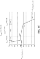
- FIGS. 4A-4D depict graphs showing examples of the surface temperatures achieved due to the insulating coating on the cooling gallery and undercrown surfaces of the example embodiments.
- FIGS. 1, 1A-3 illustrate respective pistons 20 , 20 ′, 20 ′′, 20 ′′′ for an internal combustion engine according to different example embodiments of the invention.
- the pistons 20 , 20 ′, 20 ′′, 20 ′′′ are discussed hereafter using the same reference numerals to identify like features.
- the pistons 20 , 20 ′, 20 ′′, 20 ′′′ each have a body 22 formed of a metal material, such as steel extending along a center axis A, along which the pistons 20 , 20 ′, 20 ′′, 20 ′′′ reciprocate in use, from an upper end 24 to a lower end 26 .
- the body 22 of the pistons 20 , 20 ′, 20 ′′, 20 ′′′ include a crown 28 at the upper end 24 of an upper combustion wall 29 , wherein the crown 28 is directly exposed to a combustion chamber and hot gases therein during use, with a combustion bowl 30 depending therein.
- the combustion bowl 30 of the body 22 presents an apex region 31 about the center axis A, a concave, toroidal bowl-shaped valley region 33 surrounding the center axis A, and a bowl-rim 35 surrounding the valley 33 .
- An annular ring belt 32 depends from the crown 28 to present a plurality of ring grooves 37 facing away from the center axis A and extending circumferentially around the center axis A.
- the pistons 20 , 20 ′, 20 ′′, 20 ′′′ further include a lower part presenting a pair of pin bosses 34 , each depending from the crown 28 , having pin bores 36 aligned with one another along a pin bore axis 38 extending perpendicular to the center axis A for receiving a wrist pin (not shown).
- the body 22 also includes a pair of diametrically opposite skirt panels 40 depending from the crown 28 and extending along a circumferential direction partially about the center axis A along opposite sides of the pin bore axis 38 .
- the skirt panels 40 are joined to the pin bosses 34 via strut portions 42 . It is noted that the body 22 of the pistons 20 , 20 ′, 20 ′′, 20 ′′′ could comprise various other designs and features than those shown in FIGS. 1, 1A-3 .
- the lower part of the body 22 of the piston 20 also presents an undercrown surface 44 on an opposite side of the upper combustion wall 29 from the crown 28 , and facing opposite the combustion bowl 30 .
- the piston 20 can optionally include an outer cooling gallery 46 in addition to the undercrown surface 44 , as shown in FIGS. 1, 1A .
- the outer cooling gallery 46 is disposed adjacent the ring belt 32 in radial alignment or substantial radial alignment therewith (substantial is intended to mean that at least a portion of the outer cooling gallery 46 is radially aligned with the ring belt 32 , but a portion may not be radially aligned with the ring belt 32 ), wherein the cooling gallery 46 extends circumferentially around the center axis A.
- the outer cooling gallery 46 can be sealed to contain a cooling media therein, which can be a solid, liquid, and/or gas. According to one embodiment, the sealed outer cooling gallery 46 can be filled with air. Otherwise, as shown in FIG. 1A , the outer cooling gallery 46 can be open, thereby including inlet and outlet openings 48 , 49 , such that cooling oil from a crankcase can enter and exit the outer cooling gallery 46 , such as by being sprayed into the inlet opening 48 and allowed to exit the outlet opening 49 . If desired, the inlet and outlet openings 48 , 49 can be sealed, for example a plug, adhesive, weld, or braze, with the desired cooling medium disposed therein, to form the sealed cooling gallery of FIG. 1 .
- the piston 20 , 20 ′ includes a central portion of the undercrown surface 44 located along the center axis A and surrounded by the sealed or open outer cooling gallery 46 .
- the central portion of the undercrown surface 44 is open and shown located directly opposite the apex region 31 of the combustion bowl 30 so that cooling oil from the crankcase can be sprayed or splashed onto the central portion of the undercrown surface 44 .
- the central portion of the undercrown surface 44 could alternatively be closed or sealed off from direct exposure to the crankshaft region.
- a further portion of the undercrown surface 44 is formed by the uppermost surfaces of the open or sealed outer cooling gallery 46 opposite the valley region 33 .
- the piston 20 ′′ does not include a closed or sealed outer cooling gallery, but instead includes an open outer galleryless region 46 ′ and the central portion of the undercrown surface 44 , which are both openly exposed along the lower part of the piston 20 ′′.
- the open galleryless region 46 ′ is shown as extending only along a pair of diametrically opposite regions of the piston 20 ′′, wherein one of the regions extends along one side of the pin bore axis 38 generally parallel thereto and generally transversely to a thrust axis axis 38 ′, and the other of the other of the regions extends along another side of the pin bore axis 38 generally parallel thereto and generally transversely to the thrust axis 38 ′.
- the open galleryless region 46 ′ is formed to extend along opposite sides of the pin bore axis 38 , radially inwardly from the skirt panels 40 and in radial alignment with or substantial radial alignment with the ring belt 32 .
- a further outer portion of the undercrown surface 44 is formed by the uppermost surfaces of the outer galleryless region 46 ′, and portions of the pin bosses 34 located above the pin bores 36 and extending to the ring belt 32 are solid piston body material.
- the central portion of the undercrown surface 44 and the outer portion of the undercrown surface 44 extends from the center axis A to the regions of the ring belt 32 located in axial alignment with the skirt panels 40 .
- the piston 20 ′′′ is similar to the piston 20 ′′; however, rather than having an entirely solid piston body portion above and axially aligned with the pin bosses 34 , extending to the ring belt 32 , a pocket or second open outer galleryless region 46 ′′ is located radially outwardly of the pin bosses 34 adjacent and in radial alignment with the ring belt 32 .
- the second open outer galleryless region 46 ′′ allows the cooling of the entirety or substantial entirety of the ring belt region 32 to be enhanced via the combined circumferentially continuous configuration provided by the first and second galleryless regions 46 ′, 46 ′′.
- the undercrown surface 44 is provided by the combination of the uppermost surfaces/portions of the open galleryless regions 46 ′, 46 ′′ generally opposite the valley region 33 of the combustion bowl 30 and the central portion of the undercrown surface 44 opposite the apex region 31 of the combustion bowl 30 .
- An insulating coating 50 is applied to at least a portion of the undercrown surface 44 , and thus, to at least one of the undercrown outer portions provided by the outer cooling gallery 46 , and/or outer galleryless regions 46 ′, 46 ′′, and/or the central portion of the undercrown surface 44 , to reduce the temperature of the surfaces being covered thereby, and thus, reduce carbon deposits and oil coking.
- At least one layer of the insulating coating 50 is applied, but multiple layers can be applied to reduce surface roughness, fill in porosity, and create anti-stick properties to reduce carbon deposits and oil coking.
- the insulating coating 50 has a thermal conductivity which is lower than a thermal conductivity of the metal material used to form the piston 20 , 20 ′, 20 ′′, 20 ′′′.
- Various different compositions can be used to form the insulating coating 50 .
- the insulating coating 50 is formed of a polymer-based, ceramic-based, or other low thermal conductivity material.
- the insulating coating 50 includes a polymer based material, including at least one of epoxy, phenolic, fluoropolymer and siloxane materials.
- the polymer based materials in general have a lower thermal conductivity than piston materials. It is to be recognized that any desired combination of two or more the aforementioned polymer-based materials may be used in combination with one another.
- the insulating coating 50 includes a ceramic material, specifically at least one of ceria, ceria stabilized zirconia, and ceria/yttria stabilized zirconia.
- the ceramic material has a low thermal conductivity, such as less than 1 W/m ⁇ K.
- the ceria used in the ceramic material makes the insulating coating 50 more stable under the high temperatures, pressures, and other harsh conditions of the engine.
- the composition of the ceramic material also makes it less susceptible to chemical attack than other ceramic coatings, such as coatings formed of yttria stabilized zirconia, which can also be used, but are more prone to delamination, destabilization through thermal effects and chemical attack in diesel combustion engines.
- Ceria and ceria stabilized zirconia are much more stable under such thermal and chemical conditions.
- Ceria has a thermal expansion coefficient which is similar to the steel material used to form the piston body 22 .
- the thermal expansion coefficient of ceria at room temperature ranges from 10E ⁇ 6 to 11E ⁇ 6, and the thermal expansion coefficient of steel at room temperature ranges from 11E ⁇ 6 to 14E ⁇ 6.
- the similar thermal expansion coefficients help to avoid thermal mismatches that produce stress cracks.
- the ceramic material used to form the insulating coating 50 includes ceria in an amount of 90 to 100 wt. %, based on the total weight of the ceramic material.
- the ceramic material includes ceria stabilized zirconia in an amount of 90 to 100 wt. %, based on the total weight of the ceramic material.
- the ceramic material includes ceria/yttria stabilized zirconia in an amount of 90 to 100 wt. %, based on the total weight of the ceramic material.
- about 50 wt. % of the zirconia is stabilized by ceria and about 50 wt. % of the zirconia is stabilized by yttria, based on the total weight of the ceramic material.
- the insulating coating 50 can be applied in a gradient structure to avoid discrete metal/ceramic interfaces.
- the gradient structure helps to mitigate stress build up through thermal mismatches and reduces the tendency to form a continuous weak oxide boundary layer at the bond material/ceramic interface. In other words, the gradient structure avoids sharp interfaces. Thus, the insulating coating 50 is less likely to de-bond during service.
- the gradient structure of the insulating coating 50 is formed by first applying a metal bond material to at least a portion of the undercrown surface 44 provided by the central portion or the undercrown surface 44 , and/or the outer cooling gallery 46 , and/or the outer galleryless region 46 ′, 46 ′′.
- the composition of the metal bond material can be the same as the material used to form the body 22 of the piston 20 , 20 ′, 20 ′′, 20 ′′′ for example a steel powder.
- the metal bond material can comprise a high performance superalloy, such as those used in coatings of jet turbines.
- the gradient structure is formed by gradually transitioning from 100% metal bond material to 100% ceramic material.
- the insulating coating 50 includes the metal bond material applied to the desired portion(s) of the undercrown surface 44 , and followed by increasing amounts of the ceramic material and reduced amounts of the metal bond material.
- the uppermost portion of the insulating coating 50 is formed entirely of the ceramic material.
- the insulating coating 50 has been found to adhere well to the steel piston body 22 . However, for additional mechanical anchoring, broken edges, such as pockets, recesses, rounded edges, and/or chamfers can be machined along the undercrown surface 44 . These features help to avoid stress concentrations in the insulating coating 50 and avoid sharp corners or edges that could cause failure of the insulating coating 50 . The machined pockets or recesses mechanically lock the insulating coating 50 in place, again reducing the probability of delamination failure.
- the insulating coating 50 can reduce the temperature of the undercrown surface 44 and thus the temperature of the lower part of the body 22 of the piston 20 , 20 ′, 20 ′′, 20 ′′′.
- the insulating coating 50 can also minimize deposits, minimize oil degradation in the engine, and/or reduce heat flow through the piston 20 , 20 ′, 20 ′′, 20 ′′′.
- FIGS. 4A-4D include graphs showing an example of the reduced heat transfer and temperatures achieved in the piston 20 , 20 ′, 20 ′′, 20 ′′′ due to the insulating coating 50 .
- Another aspect of the invention provides a method of manufacturing the piston 20 , 20 ′, 20 ′′, 20 ′′′ including the insulating coating 50 .
- the body 22 of the piston 20 , 20 ′, 20 ′′, 20 ′′′ which is typically formed of steel, can be manufactured according to various different methods, such as forging or casting.
- the body 22 of the piston 20 , 20 ′, 20 ′′, 20 ′′′ can also comprise various different designs, and examples of the designs are shown in FIGS. 1, 1A-3 .
- the method further includes applying the insulating coating 50 to at least a portion of the undercrown surface 44 , including at least a portion of the central portion of the undercrown surface 44 , and/or at least a portion of the outer cooling gallery 46 , and/or at least a portion of the first and/or second open outer galleryless region 46 ′, 46 ′′.
- the insulating coating 50 can be spray coated, plated, cast, or in any way permanently attached the steel body 22 of the piston 20 , 20 ′, 20 ′′, 20 ′′′.
- the insulating coating 50 is applied by thermal spraying.
- the method can include applying the metal bond material and the ceramic material by a thermal spray technique, such as plasma spraying.
- High velocity Oxy-Fuel (HVOF) spraying is an alternative that gives a denser coating, but it is a more expensive process.
- Other methods of applying the insulating coating 50 to the piston 20 , 20 ′, 20 ′′, 20 ′′′ can also be used.
- the example method begins by spraying the metal bond material in an amount of 100 wt. % and the ceramic material in an amount of 0 wt. %, based on the total weight of the insulating coating 50 .
- an increasing amount of ceramic material is added to the composition, while the amount of metal bond material is reduced.
- the composition of the insulating coating 50 gradually changes from 100% metal bond material at the piston body 22 to 100% ceramic material at the outermost surface of the insulating coating 50 .
- Multiple powder feeders are typically used to apply the insulating coating 50 , and their feed rates are adjusted to achieve the gradient structure.
- the insulating coating 50 is preferably applied to a thickness of less than 500 microns. The gradient structure of the insulating coating 50 is achieved during the thermal spray process.
- the broken edges or features that aid in mechanical locking and reduce stress risers can be machined into the undercrown surface 44 of the piston 20 , 20 ′, 20 ′′, 20 ′′′ to which the insulating coating 50 is applied, for example by turning, milling or any other appropriate means.
- the undercrown surface 44 is then washed in solvent to remove contamination.
- the method can also include grit blasting the surface to improve adhesion of the insulating coating 50 .
Landscapes
- Engineering & Computer Science (AREA)
- Chemical & Material Sciences (AREA)
- Mechanical Engineering (AREA)
- Combustion & Propulsion (AREA)
- General Engineering & Computer Science (AREA)
- Chemical Kinetics & Catalysis (AREA)
- Materials Engineering (AREA)
- Metallurgy (AREA)
- Organic Chemistry (AREA)
- Pistons, Piston Rings, And Cylinders (AREA)
Abstract
Description
Claims (24)
Priority Applications (7)
| Application Number | Priority Date | Filing Date | Title |
|---|---|---|---|
| US15/598,564 US10859033B2 (en) | 2016-05-19 | 2017-05-18 | Piston having an undercrown surface with insulating coating and method of manufacture thereof |
| BR112018073513A BR112018073513A2 (en) | 2016-05-19 | 2017-05-19 | piston having an insulating coated lower surface of the crown and method of fabrication thereof |
| PCT/US2017/033444 WO2017201354A1 (en) | 2016-05-19 | 2017-05-19 | Piston having an undercrown surface with insulating coating and method of manufacture thereof |
| CN201780030356.1A CN109154251B (en) | 2016-05-19 | 2017-05-19 | Piston having top and bottom surfaces with insulative coating and method of making same |
| EP17726462.9A EP3458700A1 (en) | 2016-05-19 | 2017-05-19 | Piston having an undercrown surface with insulating coating and method of manufacture thereof |
| KR1020187034156A KR20190008256A (en) | 2016-05-19 | 2017-05-19 | Piston with undercrown surface with insulating coating and method of making same |
| JP2018560530A JP2019516901A (en) | 2016-05-19 | 2017-05-19 | Piston having an under crown surface having an insulating covering layer and method of manufacturing the same |
Applications Claiming Priority (2)
| Application Number | Priority Date | Filing Date | Title |
|---|---|---|---|
| US201662339053P | 2016-05-19 | 2016-05-19 | |
| US15/598,564 US10859033B2 (en) | 2016-05-19 | 2017-05-18 | Piston having an undercrown surface with insulating coating and method of manufacture thereof |
Publications (2)
| Publication Number | Publication Date |
|---|---|
| US20170335792A1 US20170335792A1 (en) | 2017-11-23 |
| US10859033B2 true US10859033B2 (en) | 2020-12-08 |
Family
ID=58794209
Family Applications (1)
| Application Number | Title | Priority Date | Filing Date |
|---|---|---|---|
| US15/598,564 Active 2038-06-05 US10859033B2 (en) | 2016-05-19 | 2017-05-18 | Piston having an undercrown surface with insulating coating and method of manufacture thereof |
Country Status (7)
| Country | Link |
|---|---|
| US (1) | US10859033B2 (en) |
| EP (1) | EP3458700A1 (en) |
| JP (1) | JP2019516901A (en) |
| KR (1) | KR20190008256A (en) |
| CN (1) | CN109154251B (en) |
| BR (1) | BR112018073513A2 (en) |
| WO (1) | WO2017201354A1 (en) |
Families Citing this family (6)
| Publication number | Priority date | Publication date | Assignee | Title |
|---|---|---|---|---|
| US11168643B2 (en) * | 2018-02-21 | 2021-11-09 | Tenneco Inc. | Coating to reduce coking deposits on steel pistons |
| US10731598B2 (en) * | 2018-10-18 | 2020-08-04 | Tenneco Inc. | Piston having an undercrown surface with coating and method of manufacture thereof |
| US20200217269A1 (en) * | 2019-01-04 | 2020-07-09 | Tenneco Inc. | Piston having an undercrown surface with insulating coating and method of manufacture thereof |
| DE102019207482A1 (en) * | 2019-05-22 | 2020-03-26 | Audi Ag | Piston for an internal combustion engine, method for producing a piston and internal combustion engine with at least one piston |
| DE102019209363A1 (en) * | 2019-06-27 | 2020-03-26 | Audi Ag | Internal combustion engine with a piston and a coolant spray nozzle |
| CN113250847A (en) * | 2021-06-29 | 2021-08-13 | 潍柴动力股份有限公司 | Piston, method for producing a thermal barrier coating for a piston, and internal combustion engine |
Citations (49)
| Publication number | Priority date | Publication date | Assignee | Title |
|---|---|---|---|---|
| US1559439A (en) * | 1925-01-16 | 1925-10-27 | Edward W Kapraun | Internal-combustion engine |
| US4450610A (en) * | 1980-10-24 | 1984-05-29 | Audi Nsu Auto Union Aktiengesellschaft | Method of making a piston |
| US4599270A (en) | 1984-05-02 | 1986-07-08 | The Perkin-Elmer Corporation | Zirconium oxide powder containing cerium oxide and yttrium oxide |
| US4610967A (en) | 1983-12-27 | 1986-09-09 | Ngk Insulators, Ltd. | Zirconia porcelain and method of manufacturing the same |
| US4712600A (en) * | 1985-07-12 | 1987-12-15 | Toyota Jidosha Kabushiki Kaisha | Production of pistons having a cavity |
| US4891343A (en) * | 1988-08-10 | 1990-01-02 | W. R. Grace & Co.-Conn. | Stabilized zirconia |
| US4977114A (en) * | 1986-11-28 | 1990-12-11 | Sumitomo Chemical Company, Limited | Zirconia ceramics and method for producing same |
| US5063894A (en) * | 1989-11-11 | 1991-11-12 | Kolbenschmidt Aktiengesellschaft | Pressure-diecast light-alloy piston for internal combustion engines |
| JPH0457650U (en) | 1990-09-20 | 1992-05-18 | ||
| US5174193A (en) * | 1990-06-23 | 1992-12-29 | T&N Technology Limited | Pistons for engines or motors |
| US5236787A (en) * | 1991-07-29 | 1993-08-17 | Caterpillar Inc. | Thermal barrier coating for metallic components |
| US5320909A (en) * | 1992-05-29 | 1994-06-14 | United Technologies Corporation | Ceramic thermal barrier coating for rapid thermal cycling applications |
| US5384200A (en) | 1991-12-24 | 1995-01-24 | Detroit Diesel Corporation | Thermal barrier coating and method of depositing the same on combustion chamber component surfaces |
| US5455000A (en) * | 1994-07-01 | 1995-10-03 | Massachusetts Institute Of Technology | Method for preparation of a functionally gradient material |
| GB2307193A (en) | 1995-11-17 | 1997-05-21 | Daimler Benz Ag | Combustion engine and method for applying a heat-insulating layer |
| US5658837A (en) * | 1994-09-23 | 1997-08-19 | Aisimag Technical Ceramics, Inc. | Stabilized zirconia |
| US6117560A (en) * | 1996-12-12 | 2000-09-12 | United Technologies Corporation | Thermal barrier coating systems and materials |
| US6513477B1 (en) * | 2001-09-19 | 2003-02-04 | Federal-Mogul World Wide, Inc. | Closed gallery piston having pin bore lubrication |
| US20030051694A1 (en) * | 2001-09-19 | 2003-03-20 | Federal-Mogul World Wide, Inc. | Closed gallery piston having con rod lubrication |
| US6656600B2 (en) | 2001-08-16 | 2003-12-02 | Honeywell International Inc. | Carbon deposit inhibiting thermal barrier coating for combustors |
| US20070113802A1 (en) * | 2004-01-07 | 2007-05-24 | Kenji Mihara | Piston for internal combustion engine |
| US20080167403A1 (en) * | 2005-02-15 | 2008-07-10 | Ks Kolbenschmidt Gmbh | Antiadhesive Coating For Preventing Carbon Build-Up |
| US20100236516A1 (en) * | 2009-03-17 | 2010-09-23 | Hitachi Automotive Systems, Ltd. | Piston for Internal Combustion Engine and Piston Surface Treatment Method |
| US20110030645A1 (en) * | 2009-08-06 | 2011-02-10 | Jose Rebello | Low thermal conductivity piston and method of construction thereof |
| US20110048017A1 (en) | 2009-08-27 | 2011-03-03 | General Electric Company | Method of depositing protective coatings on turbine combustion components |
| US8053089B2 (en) | 2009-09-30 | 2011-11-08 | General Electric Company | Single layer bond coat and method of application |
| US20120082841A1 (en) * | 2010-09-30 | 2012-04-05 | Mazda Motor Corporation | Heat-insulating structure |
| US20120118255A1 (en) * | 2009-04-29 | 2012-05-17 | Christian Jung | Water-dilutable antifriction lacquer for coating engine pistons |
| US20120258266A1 (en) * | 2011-04-06 | 2012-10-11 | Basf Corporation | Coatings For Engine And Powertrain Components To Prevent Buildup Of Deposits |
| US20130133609A1 (en) * | 2011-11-28 | 2013-05-30 | Eduardo Matsuo | Piston with anti-carbon deposit coating and method of construction thereof |
| US20130180494A1 (en) * | 2011-11-28 | 2013-07-18 | Federal-Mogul Corporation | Piston with anti-carbon deposit coating and method of construction thereof |
| US20130189441A1 (en) * | 2012-01-20 | 2013-07-25 | General Electric Company | Process of fabricating thermal barrier coatings |
| US20130205991A1 (en) * | 2012-02-15 | 2013-08-15 | Hitachi Automotive Systems, Ltd. | Method of Producing Piston of Internal Combustion Engine |
| JP2014034917A (en) * | 2012-08-08 | 2014-02-24 | Hino Motors Ltd | Piston structure of engine |
| US20140123930A1 (en) * | 2012-11-02 | 2014-05-08 | Federal-Mogul Corporation | Piston With a Cooling Gallery Partially Filled With a Thermally Conductive Metal-Containing Composition |
| US8877031B2 (en) | 2008-12-26 | 2014-11-04 | Nihon Parkerizing Co., Ltd. | Method of electrolytic ceramic coating for metal, electrolysis solution for electrolytic ceramic coating for metal, and metallic material |
| US20150030871A1 (en) * | 2013-07-26 | 2015-01-29 | Gerald J. Bruck | Functionally graded thermal barrier coating system |
| US20150104626A1 (en) * | 2012-06-20 | 2015-04-16 | Ngk Insulators, Ltd. | Porous Plate-Shaped Filler, Coating Composition, Heat-Insulating Film, and Heat-Insulating Film Structure |
| US20150204269A1 (en) * | 2012-08-10 | 2015-07-23 | Aisin Seiki Kabushiki Kaisha | Engine and piston |
| US20160130519A1 (en) | 2014-11-06 | 2016-05-12 | Baker Hughes Incorporated | Methods for preparing anti-friction coatings |
| US20170138296A1 (en) * | 2015-11-18 | 2017-05-18 | Federal-Mogul Corporation | Piston providing for reduced heat loss using cooling media |
| US20170145914A1 (en) * | 2015-11-20 | 2017-05-25 | Federal-Mogul Corporation | Thermally insulated engine components and method of making using a ceramic coating |
| US20170145952A1 (en) * | 2015-11-20 | 2017-05-25 | Federal-Mogul Corporation | Thermally insulated steel piston crown and method of making using a ceramic coating |
| US20170241371A1 (en) * | 2016-02-22 | 2017-08-24 | Federal-Mogul Llc | Insulation layer on steel pistons without gallery |
| US20170268457A1 (en) * | 2016-03-16 | 2017-09-21 | Federal-Mogul Llc | Piston with advanced catalytic energy release |
| US20170284334A1 (en) * | 2016-04-05 | 2017-10-05 | Federal-Mogul, LLC | Piston with thermally insulating insert and method of construction thereof |
| US20180128166A1 (en) * | 2015-11-20 | 2018-05-10 | Federal-Mogul Llc | Steel piston crown and/or combustion engine components with dynamic thermal insulation coating and method of making and using such a coating |
| US20180216524A1 (en) * | 2015-11-20 | 2018-08-02 | Federal-Mogul Llc | Combustion engine components with dynamic thermal insulation coating and method of making and using such a coating |
| US20180236555A1 (en) * | 2017-02-17 | 2018-08-23 | Federal-Mogul Llc | Steel piston with metallurgically bonded bushing and method of manufacturing |
-
2017
- 2017-05-18 US US15/598,564 patent/US10859033B2/en active Active
- 2017-05-19 EP EP17726462.9A patent/EP3458700A1/en not_active Withdrawn
- 2017-05-19 WO PCT/US2017/033444 patent/WO2017201354A1/en unknown
- 2017-05-19 CN CN201780030356.1A patent/CN109154251B/en active Active
- 2017-05-19 JP JP2018560530A patent/JP2019516901A/en active Pending
- 2017-05-19 BR BR112018073513A patent/BR112018073513A2/en not_active IP Right Cessation
- 2017-05-19 KR KR1020187034156A patent/KR20190008256A/en not_active Application Discontinuation
Patent Citations (55)
| Publication number | Priority date | Publication date | Assignee | Title |
|---|---|---|---|---|
| US1559439A (en) * | 1925-01-16 | 1925-10-27 | Edward W Kapraun | Internal-combustion engine |
| US4450610A (en) * | 1980-10-24 | 1984-05-29 | Audi Nsu Auto Union Aktiengesellschaft | Method of making a piston |
| US4610967A (en) | 1983-12-27 | 1986-09-09 | Ngk Insulators, Ltd. | Zirconia porcelain and method of manufacturing the same |
| US4599270A (en) | 1984-05-02 | 1986-07-08 | The Perkin-Elmer Corporation | Zirconium oxide powder containing cerium oxide and yttrium oxide |
| US4712600A (en) * | 1985-07-12 | 1987-12-15 | Toyota Jidosha Kabushiki Kaisha | Production of pistons having a cavity |
| US4977114A (en) * | 1986-11-28 | 1990-12-11 | Sumitomo Chemical Company, Limited | Zirconia ceramics and method for producing same |
| US4891343A (en) * | 1988-08-10 | 1990-01-02 | W. R. Grace & Co.-Conn. | Stabilized zirconia |
| US5063894A (en) * | 1989-11-11 | 1991-11-12 | Kolbenschmidt Aktiengesellschaft | Pressure-diecast light-alloy piston for internal combustion engines |
| US5174193A (en) * | 1990-06-23 | 1992-12-29 | T&N Technology Limited | Pistons for engines or motors |
| JPH0457650U (en) | 1990-09-20 | 1992-05-18 | ||
| US5236787A (en) * | 1991-07-29 | 1993-08-17 | Caterpillar Inc. | Thermal barrier coating for metallic components |
| US5384200A (en) | 1991-12-24 | 1995-01-24 | Detroit Diesel Corporation | Thermal barrier coating and method of depositing the same on combustion chamber component surfaces |
| US5320909A (en) * | 1992-05-29 | 1994-06-14 | United Technologies Corporation | Ceramic thermal barrier coating for rapid thermal cycling applications |
| US5455000A (en) * | 1994-07-01 | 1995-10-03 | Massachusetts Institute Of Technology | Method for preparation of a functionally gradient material |
| US5658837A (en) * | 1994-09-23 | 1997-08-19 | Aisimag Technical Ceramics, Inc. | Stabilized zirconia |
| GB2307193A (en) | 1995-11-17 | 1997-05-21 | Daimler Benz Ag | Combustion engine and method for applying a heat-insulating layer |
| US5722379A (en) * | 1995-11-17 | 1998-03-03 | Daimler-Benz Ag | Internal-combustion engine and process for applying a thermal barrier layer |
| US6117560A (en) * | 1996-12-12 | 2000-09-12 | United Technologies Corporation | Thermal barrier coating systems and materials |
| US6656600B2 (en) | 2001-08-16 | 2003-12-02 | Honeywell International Inc. | Carbon deposit inhibiting thermal barrier coating for combustors |
| US6513477B1 (en) * | 2001-09-19 | 2003-02-04 | Federal-Mogul World Wide, Inc. | Closed gallery piston having pin bore lubrication |
| US20030051694A1 (en) * | 2001-09-19 | 2003-03-20 | Federal-Mogul World Wide, Inc. | Closed gallery piston having con rod lubrication |
| US20070113802A1 (en) * | 2004-01-07 | 2007-05-24 | Kenji Mihara | Piston for internal combustion engine |
| US20080167403A1 (en) * | 2005-02-15 | 2008-07-10 | Ks Kolbenschmidt Gmbh | Antiadhesive Coating For Preventing Carbon Build-Up |
| US8877031B2 (en) | 2008-12-26 | 2014-11-04 | Nihon Parkerizing Co., Ltd. | Method of electrolytic ceramic coating for metal, electrolysis solution for electrolytic ceramic coating for metal, and metallic material |
| US20100236516A1 (en) * | 2009-03-17 | 2010-09-23 | Hitachi Automotive Systems, Ltd. | Piston for Internal Combustion Engine and Piston Surface Treatment Method |
| US20120118255A1 (en) * | 2009-04-29 | 2012-05-17 | Christian Jung | Water-dilutable antifriction lacquer for coating engine pistons |
| US20110030645A1 (en) * | 2009-08-06 | 2011-02-10 | Jose Rebello | Low thermal conductivity piston and method of construction thereof |
| US20110048017A1 (en) | 2009-08-27 | 2011-03-03 | General Electric Company | Method of depositing protective coatings on turbine combustion components |
| US8053089B2 (en) | 2009-09-30 | 2011-11-08 | General Electric Company | Single layer bond coat and method of application |
| US20120082841A1 (en) * | 2010-09-30 | 2012-04-05 | Mazda Motor Corporation | Heat-insulating structure |
| US20120258266A1 (en) * | 2011-04-06 | 2012-10-11 | Basf Corporation | Coatings For Engine And Powertrain Components To Prevent Buildup Of Deposits |
| US9163579B2 (en) | 2011-11-28 | 2015-10-20 | Federal-Mogul Corporation | Piston with anti-carbon deposit coating and method of construction thereof |
| US20130133609A1 (en) * | 2011-11-28 | 2013-05-30 | Eduardo Matsuo | Piston with anti-carbon deposit coating and method of construction thereof |
| US20130180494A1 (en) * | 2011-11-28 | 2013-07-18 | Federal-Mogul Corporation | Piston with anti-carbon deposit coating and method of construction thereof |
| US9169800B2 (en) | 2011-11-28 | 2015-10-27 | Federal-Mogul Corporation | Piston with anti-carbon deposit coating and method of construction thereof |
| US20130189441A1 (en) * | 2012-01-20 | 2013-07-25 | General Electric Company | Process of fabricating thermal barrier coatings |
| US20130205991A1 (en) * | 2012-02-15 | 2013-08-15 | Hitachi Automotive Systems, Ltd. | Method of Producing Piston of Internal Combustion Engine |
| US20150104626A1 (en) * | 2012-06-20 | 2015-04-16 | Ngk Insulators, Ltd. | Porous Plate-Shaped Filler, Coating Composition, Heat-Insulating Film, and Heat-Insulating Film Structure |
| JP2014034917A (en) * | 2012-08-08 | 2014-02-24 | Hino Motors Ltd | Piston structure of engine |
| US20150204269A1 (en) * | 2012-08-10 | 2015-07-23 | Aisin Seiki Kabushiki Kaisha | Engine and piston |
| US20140123930A1 (en) * | 2012-11-02 | 2014-05-08 | Federal-Mogul Corporation | Piston With a Cooling Gallery Partially Filled With a Thermally Conductive Metal-Containing Composition |
| US9127619B2 (en) * | 2012-11-02 | 2015-09-08 | Federal-Mogul Corporation | Piston with a cooling gallery partially filled with a thermally conductive metal-containing composition |
| US20150030871A1 (en) * | 2013-07-26 | 2015-01-29 | Gerald J. Bruck | Functionally graded thermal barrier coating system |
| US20160130519A1 (en) | 2014-11-06 | 2016-05-12 | Baker Hughes Incorporated | Methods for preparing anti-friction coatings |
| WO2017087433A1 (en) | 2015-11-18 | 2017-05-26 | Federal-Mogul Corporation | Piston providing for reduced heat loss using cooling media |
| US20170138296A1 (en) * | 2015-11-18 | 2017-05-18 | Federal-Mogul Corporation | Piston providing for reduced heat loss using cooling media |
| US20170145914A1 (en) * | 2015-11-20 | 2017-05-25 | Federal-Mogul Corporation | Thermally insulated engine components and method of making using a ceramic coating |
| US20170145952A1 (en) * | 2015-11-20 | 2017-05-25 | Federal-Mogul Corporation | Thermally insulated steel piston crown and method of making using a ceramic coating |
| US20180128166A1 (en) * | 2015-11-20 | 2018-05-10 | Federal-Mogul Llc | Steel piston crown and/or combustion engine components with dynamic thermal insulation coating and method of making and using such a coating |
| US20180216524A1 (en) * | 2015-11-20 | 2018-08-02 | Federal-Mogul Llc | Combustion engine components with dynamic thermal insulation coating and method of making and using such a coating |
| US20170241371A1 (en) * | 2016-02-22 | 2017-08-24 | Federal-Mogul Llc | Insulation layer on steel pistons without gallery |
| US20190211774A1 (en) * | 2016-02-22 | 2019-07-11 | Tenneco Inc. | Insulation layer on steel pistons |
| US20170268457A1 (en) * | 2016-03-16 | 2017-09-21 | Federal-Mogul Llc | Piston with advanced catalytic energy release |
| US20170284334A1 (en) * | 2016-04-05 | 2017-10-05 | Federal-Mogul, LLC | Piston with thermally insulating insert and method of construction thereof |
| US20180236555A1 (en) * | 2017-02-17 | 2018-08-23 | Federal-Mogul Llc | Steel piston with metallurgically bonded bushing and method of manufacturing |
Non-Patent Citations (5)
| Title |
|---|
| Handbook of Thermal Spray Technology, Introduction to Thermal Spray Processing, 2004, ASM International, pp. 3-13 (Year: 2004). * |
| International Search Report, dated Aug. 2, 2017 (PCT/US2017/033444). |
| Klod Kokini and Sudarshan V. Rangaraj, Time-Dependent Behavior and Fracture of Functionally Graded Thermal Barrier Coatings Under Thermal Shock, Aug. 15, 2005, Trans Tech Publications, Material Science Forum, ISSN: 1662-9752, vols. 492-493, pp. 379-384 (Year: 2005). * |
| M. B. Beardsley, Final Report of Thick Thermal Barrier Coatings (TTBCs) for Low Emmission, High Efficiency Diesel Engine Components, Prepared for Assistant Secretary for Energy Efficiency and Renewable Energy, Office of Transportation Technologies As part of the Ceramic Technology Project of the Materials, Development Program, under contract FC05-970R22580, Mar. 26, 2006, 144 pages. |
| Ralph A. Corvino, Ceramic Coating Diesel Engine Combustion Components, 1989, pp. 43-44. |
Also Published As
| Publication number | Publication date |
|---|---|
| BR112018073513A2 (en) | 2019-03-26 |
| US20170335792A1 (en) | 2017-11-23 |
| CN109154251B (en) | 2021-10-12 |
| KR20190008256A (en) | 2019-01-23 |
| CN109154251A (en) | 2019-01-04 |
| JP2019516901A (en) | 2019-06-20 |
| WO2017201354A1 (en) | 2017-11-23 |
| EP3458700A1 (en) | 2019-03-27 |
Similar Documents
| Publication | Publication Date | Title |
|---|---|---|
| US10578050B2 (en) | Thermally insulated steel piston crown and method of making using a ceramic coating | |
| US10859033B2 (en) | Piston having an undercrown surface with insulating coating and method of manufacture thereof | |
| US10995661B2 (en) | Thermally insulated engine components using a ceramic coating | |
| US10273902B2 (en) | Insulation layer on steel pistons without gallery | |
| US10876475B2 (en) | Steel piston crown and/or combustion engine components with dynamic thermal insulation coating and method of making and using such a coating | |
| US11111851B2 (en) | Combustion engine components with dynamic thermal insulation coating and method of making and using such a coating | |
| WO2019084373A1 (en) | Steel piston crown and/or combustion engine components with dynamic thermal insulation coating and method of making and using such a coating | |
| US10731598B2 (en) | Piston having an undercrown surface with coating and method of manufacture thereof | |
| US20200217269A1 (en) | Piston having an undercrown surface with insulating coating and method of manufacture thereof |
Legal Events
| Date | Code | Title | Description |
|---|---|---|---|
| AS | Assignment |
Owner name: FEDERAL-MOGUL LLC, MICHIGAN Free format text: ASSIGNMENT OF ASSIGNORS INTEREST;ASSIGNORS:MATSUO, EDUARDO;LINETON, WARRAN BOYD;REEL/FRAME:042423/0218 Effective date: 20170517 |
|
| STPP | Information on status: patent application and granting procedure in general |
Free format text: DOCKETED NEW CASE - READY FOR EXAMINATION |
|
| AS | Assignment |
Owner name: CITIBANK, N.A., AS COLLATERAL TRUSTEE, NEW YORK Free format text: GRANT OF SECURITY INTEREST IN UNITED STATES PATENTS;ASSIGNORS:FEDERAL-MOGUL LLC;FEDERAL-MOGUL PRODUCTS, INC.;FEDERAL-MOGUL MOTORPARTS LLC;AND OTHERS;REEL/FRAME:044013/0419 Effective date: 20170629 |
|
| AS | Assignment |
Owner name: BANK OF AMERICA, N.A., AS COLLATERAL TRUSTEE, MICHIGAN Free format text: COLLATERAL TRUSTEE RESIGNATION AND APPOINTMENT AGREEMENT;ASSIGNOR:CITIBANK, N.A., AS COLLATERAL TRUSTEE;REEL/FRAME:045822/0765 Effective date: 20180223 Owner name: BANK OF AMERICA, N.A., AS COLLATERAL TRUSTEE, MICH Free format text: COLLATERAL TRUSTEE RESIGNATION AND APPOINTMENT AGREEMENT;ASSIGNOR:CITIBANK, N.A., AS COLLATERAL TRUSTEE;REEL/FRAME:045822/0765 Effective date: 20180223 |
|
| AS | Assignment |
Owner name: WILMINGTON TRUST, NATIONAL ASSOCIATION, AS COLLATERAL TRUSTEE, MINNESOTA Free format text: CONFIRMATORY GRANT OF SECURITY INTERESTS IN UNITED STATES PATENTS;ASSIGNORS:TENNECO INC.;TENNECO AUTOMOTIVE OPERATING COMPANY INC.;TENNECO INTERNATIONAL HOLDING CORP.;AND OTHERS;REEL/FRAME:047223/0001 Effective date: 20181001 Owner name: WILMINGTON TRUST, NATIONAL ASSOCIATION, AS COLLATE Free format text: CONFIRMATORY GRANT OF SECURITY INTERESTS IN UNITED STATES PATENTS;ASSIGNORS:TENNECO INC.;TENNECO AUTOMOTIVE OPERATING COMPANY INC.;TENNECO INTERNATIONAL HOLDING CORP.;AND OTHERS;REEL/FRAME:047223/0001 Effective date: 20181001 |
|
| AS | Assignment |
Owner name: FEDERAL-MOGUL PRODUCTS, INC., MICHIGAN Free format text: RELEASE BY SECURED PARTY;ASSIGNOR:BANK OF AMERICA, N.A., AS COLLATERAL TRUSTEE;REEL/FRAME:047276/0771 Effective date: 20181001 Owner name: FEDERAL MOGUL POWERTRAIN LLC, MICHIGAN Free format text: RELEASE BY SECURED PARTY;ASSIGNOR:BANK OF AMERICA, N.A., AS COLLATERAL TRUSTEE;REEL/FRAME:047276/0771 Effective date: 20181001 Owner name: FEDERAL-MOGUL LLC, MICHIGAN Free format text: RELEASE BY SECURED PARTY;ASSIGNOR:BANK OF AMERICA, N.A., AS COLLATERAL TRUSTEE;REEL/FRAME:047276/0771 Effective date: 20181001 Owner name: FEDERAL-MOGUL MOTORPARTS LLC, MICHIGAN Free format text: RELEASE BY SECURED PARTY;ASSIGNOR:BANK OF AMERICA, N.A., AS COLLATERAL TRUSTEE;REEL/FRAME:047276/0771 Effective date: 20181001 Owner name: FEDERAL-MOGUL WORLD WIDE LLC, MICHIGAN Free format text: RELEASE BY SECURED PARTY;ASSIGNOR:BANK OF AMERICA, N.A., AS COLLATERAL TRUSTEE;REEL/FRAME:047276/0771 Effective date: 20181001 Owner name: FEDERAL-MOGUL IGNITION COMPANY, MICHIGAN Free format text: RELEASE BY SECURED PARTY;ASSIGNOR:BANK OF AMERICA, N.A., AS COLLATERAL TRUSTEE;REEL/FRAME:047276/0771 Effective date: 20181001 Owner name: FEDERAL-MOGUL CHASSIS LLC, MICHIGAN Free format text: RELEASE BY SECURED PARTY;ASSIGNOR:BANK OF AMERICA, N.A., AS COLLATERAL TRUSTEE;REEL/FRAME:047276/0771 Effective date: 20181001 |
|
| AS | Assignment |
Owner name: WILMINGTON TRUST, NATIONAL ASSOCIATION, AS CO-COLLATERAL TRUSTEE, SUCCESSOR COLLATERAL TRUSTEE, MINNESOTA Free format text: COLLATERAL TRUSTEE RESIGNATION AND APPOINTMENT, JOINDER, ASSUMPTION AND DESIGNATION AGREEMENT;ASSIGNOR:BANK OF AMERICA, N.A., AS CO-COLLATERAL TRUSTEE AND RESIGNING COLLATERAL TRUSTEE;REEL/FRAME:047630/0661 Effective date: 20181001 Owner name: WILMINGTON TRUST, NATIONAL ASSOCIATION, AS CO-COLL Free format text: COLLATERAL TRUSTEE RESIGNATION AND APPOINTMENT, JOINDER, ASSUMPTION AND DESIGNATION AGREEMENT;ASSIGNOR:BANK OF AMERICA, N.A., AS CO-COLLATERAL TRUSTEE AND RESIGNING COLLATERAL TRUSTEE;REEL/FRAME:047630/0661 Effective date: 20181001 |
|
| STPP | Information on status: patent application and granting procedure in general |
Free format text: NON FINAL ACTION MAILED |
|
| STPP | Information on status: patent application and granting procedure in general |
Free format text: RESPONSE TO NON-FINAL OFFICE ACTION ENTERED AND FORWARDED TO EXAMINER |
|
| STPP | Information on status: patent application and granting procedure in general |
Free format text: FINAL REJECTION MAILED |
|
| STPP | Information on status: patent application and granting procedure in general |
Free format text: ADVISORY ACTION MAILED |
|
| STPP | Information on status: patent application and granting procedure in general |
Free format text: NOTICE OF ALLOWANCE MAILED -- APPLICATION RECEIVED IN OFFICE OF PUBLICATIONS |
|
| AS | Assignment |
Owner name: TENNECO INC., ILLINOIS Free format text: MERGER AND CHANGE OF NAME;ASSIGNORS:FEDERAL-MOGUL LLC;TENNECO INC.;REEL/FRAME:054297/0375 Effective date: 20181001 |
|
| STPP | Information on status: patent application and granting procedure in general |
Free format text: PUBLICATIONS -- ISSUE FEE PAYMENT VERIFIED |
|
| STCF | Information on status: patent grant |
Free format text: PATENTED CASE |
|
| AS | Assignment |
Owner name: WILMINGTON TRUST, NATIONAL ASSOCIATION, MINNESOTA Free format text: SECURITY AGREEMENT;ASSIGNORS:TENNECO INC.;THE PULLMAN COMPANY;FEDERAL-MOGUL IGNITION LLC;AND OTHERS;REEL/FRAME:054555/0592 Effective date: 20201130 |
|
| AS | Assignment |
Owner name: WILMINGTON TRUST, NATIONAL ASSOCIATION, MINNESOTA Free format text: SECURITY AGREEMENT;ASSIGNORS:TENNECO INC.;TENNECO AUTOMOTIVE OPERATING COMPANY INC.;THE PULLMAN COMPANY;AND OTHERS;REEL/FRAME:055626/0065 Effective date: 20210317 |
|
| AS | Assignment |
Owner name: FEDERAL-MOGUL PRODUCTS US, LLC, AS SUCCESSOR TO FEDERAL-MOGUL PRODUCTS, INC., MICHIGAN Free format text: RELEASE BY SECURED PARTY;ASSIGNOR:WILMINGTON TRUST, NATIONAL ASSOCIATION;REEL/FRAME:056886/0455 Effective date: 20210317 Owner name: FEDERAL-MOGUL WORLD WIDE, INC., AS SUCCESSOR TO FEDERAL-MOGUL WORLD WIDE LLC, MICHIGAN Free format text: RELEASE BY SECURED PARTY;ASSIGNOR:WILMINGTON TRUST, NATIONAL ASSOCIATION;REEL/FRAME:056886/0455 Effective date: 20210317 Owner name: FEDERAL-MOGUL MOTORPARTS LLC, AS SUCCESSOR TO FEDERAL-MOGUL MOTORPARTS CORPORATION, MICHIGAN Free format text: RELEASE BY SECURED PARTY;ASSIGNOR:WILMINGTON TRUST, NATIONAL ASSOCIATION;REEL/FRAME:056886/0455 Effective date: 20210317 Owner name: FEDERAL-MOGUL IGNITION, LLC, AS SUCCESSOR TO FEDERAL-MOGUL IGNITION COMPANY, MICHIGAN Free format text: RELEASE BY SECURED PARTY;ASSIGNOR:WILMINGTON TRUST, NATIONAL ASSOCIATION;REEL/FRAME:056886/0455 Effective date: 20210317 Owner name: TENNECO INC., AS SUCCESSOR TO FEDERAL-MOGUL LLC, ILLINOIS Free format text: RELEASE BY SECURED PARTY;ASSIGNOR:WILMINGTON TRUST, NATIONAL ASSOCIATION;REEL/FRAME:056886/0455 Effective date: 20210317 Owner name: FEDERAL-MOGUL CHASSIS LLC, MICHIGAN Free format text: RELEASE BY SECURED PARTY;ASSIGNOR:WILMINGTON TRUST, NATIONAL ASSOCIATION;REEL/FRAME:056886/0455 Effective date: 20210317 Owner name: FEDERAL-MOGUL POWERTRAIN LLC, MICHIGAN Free format text: RELEASE BY SECURED PARTY;ASSIGNOR:WILMINGTON TRUST, NATIONAL ASSOCIATION;REEL/FRAME:056886/0455 Effective date: 20210317 Owner name: DRIV AUTOMOTIVE INC., ILLINOIS Free format text: RELEASE BY SECURED PARTY;ASSIGNOR:WILMINGTON TRUST, NATIONAL ASSOCIATION;REEL/FRAME:056886/0455 Effective date: 20210317 |
|
| AS | Assignment |
Owner name: FEDERAL-MOGUL PRODUCTS US LLC, MICHIGAN Free format text: RELEASE BY SECURED PARTY;ASSIGNOR:WILMINGTON TRUST, NATIONAL ASSOCIATION;REEL/FRAME:061975/0218 Effective date: 20221117 Owner name: FEDERAL-MOGUL FINANCING CORPORATION, MICHIGAN Free format text: RELEASE BY SECURED PARTY;ASSIGNOR:WILMINGTON TRUST, NATIONAL ASSOCIATION;REEL/FRAME:061975/0218 Effective date: 20221117 Owner name: FEDERAL-MOGUL FILTRATION LLC, MICHIGAN Free format text: RELEASE BY SECURED PARTY;ASSIGNOR:WILMINGTON TRUST, NATIONAL ASSOCIATION;REEL/FRAME:061975/0218 Effective date: 20221117 Owner name: BECK ARNLEY HOLDINGS LLC, MICHIGAN Free format text: RELEASE BY SECURED PARTY;ASSIGNOR:WILMINGTON TRUST, NATIONAL ASSOCIATION;REEL/FRAME:061975/0218 Effective date: 20221117 Owner name: FEDERAL-MOGUL SEVIERVILLE, LLC, MICHIGAN Free format text: RELEASE BY SECURED PARTY;ASSIGNOR:WILMINGTON TRUST, NATIONAL ASSOCIATION;REEL/FRAME:061975/0218 Effective date: 20221117 Owner name: FEDERAL-MOGUL VALVE TRAIN INTERNATIONAL LLC, MICHIGAN Free format text: RELEASE BY SECURED PARTY;ASSIGNOR:WILMINGTON TRUST, NATIONAL ASSOCIATION;REEL/FRAME:061975/0218 Effective date: 20221117 Owner name: F-M TSC REAL ESTATE HOLDINGS LLC, MICHIGAN Free format text: RELEASE BY SECURED PARTY;ASSIGNOR:WILMINGTON TRUST, NATIONAL ASSOCIATION;REEL/FRAME:061975/0218 Effective date: 20221117 Owner name: F-M MOTORPARTS TSC LLC, MICHIGAN Free format text: RELEASE BY SECURED PARTY;ASSIGNOR:WILMINGTON TRUST, NATIONAL ASSOCIATION;REEL/FRAME:061975/0218 Effective date: 20221117 Owner name: FEDERAL-MOGUL CHASSIS LLC, MICHIGAN Free format text: RELEASE BY SECURED PARTY;ASSIGNOR:WILMINGTON TRUST, NATIONAL ASSOCIATION;REEL/FRAME:061975/0218 Effective date: 20221117 Owner name: FEDERAL-MOGUL MOTORPARTS LLC, MICHIGAN Free format text: RELEASE BY SECURED PARTY;ASSIGNOR:WILMINGTON TRUST, NATIONAL ASSOCIATION;REEL/FRAME:061975/0218 Effective date: 20221117 Owner name: FEDERAL-MOGUL IGNITION LLC, MICHIGAN Free format text: RELEASE BY SECURED PARTY;ASSIGNOR:WILMINGTON TRUST, NATIONAL ASSOCIATION;REEL/FRAME:061975/0218 Effective date: 20221117 Owner name: FEDERAL-MOGUL PISTON RINGS, LLC, MICHIGAN Free format text: RELEASE BY SECURED PARTY;ASSIGNOR:WILMINGTON TRUST, NATIONAL ASSOCIATION;REEL/FRAME:061975/0218 Effective date: 20221117 Owner name: FEDERAL-MOGUL POWERTRAIN IP LLC, MICHIGAN Free format text: RELEASE BY SECURED PARTY;ASSIGNOR:WILMINGTON TRUST, NATIONAL ASSOCIATION;REEL/FRAME:061975/0218 Effective date: 20221117 Owner name: FEDERAL-MOGUL POWERTRAIN LLC, MICHIGAN Free format text: RELEASE BY SECURED PARTY;ASSIGNOR:WILMINGTON TRUST, NATIONAL ASSOCIATION;REEL/FRAME:061975/0218 Effective date: 20221117 Owner name: MUZZY-LYON AUTO PARTS LLC, ILLINOIS Free format text: RELEASE BY SECURED PARTY;ASSIGNOR:WILMINGTON TRUST, NATIONAL ASSOCIATION;REEL/FRAME:061975/0218 Effective date: 20221117 Owner name: FELT PRODUCTS MFG. CO. LLC, ILLINOIS Free format text: RELEASE BY SECURED PARTY;ASSIGNOR:WILMINGTON TRUST, NATIONAL ASSOCIATION;REEL/FRAME:061975/0218 Effective date: 20221117 Owner name: FEDERAL-MOGUL WORLD WIDE LLC, MICHIGAN Free format text: RELEASE BY SECURED PARTY;ASSIGNOR:WILMINGTON TRUST, NATIONAL ASSOCIATION;REEL/FRAME:061975/0218 Effective date: 20221117 Owner name: CARTER AUTOMOTIVE COMPANY LLC, ILLINOIS Free format text: RELEASE BY SECURED PARTY;ASSIGNOR:WILMINGTON TRUST, NATIONAL ASSOCIATION;REEL/FRAME:061975/0218 Effective date: 20221117 Owner name: TMC TEXAS INC., ILLINOIS Free format text: RELEASE BY SECURED PARTY;ASSIGNOR:WILMINGTON TRUST, NATIONAL ASSOCIATION;REEL/FRAME:061975/0218 Effective date: 20221117 Owner name: CLEVITE INDUSTRIES INC., OHIO Free format text: RELEASE BY SECURED PARTY;ASSIGNOR:WILMINGTON TRUST, NATIONAL ASSOCIATION;REEL/FRAME:061975/0218 Effective date: 20221117 Owner name: TENNECO GLOBAL HOLDINGS INC., ILLINOIS Free format text: RELEASE BY SECURED PARTY;ASSIGNOR:WILMINGTON TRUST, NATIONAL ASSOCIATION;REEL/FRAME:061975/0218 Effective date: 20221117 Owner name: THE PULLMAN COMPANY, OHIO Free format text: RELEASE BY SECURED PARTY;ASSIGNOR:WILMINGTON TRUST, NATIONAL ASSOCIATION;REEL/FRAME:061975/0218 Effective date: 20221117 Owner name: TENNECO INTERNATIONAL HOLDING CORP., ILLINOIS Free format text: RELEASE BY SECURED PARTY;ASSIGNOR:WILMINGTON TRUST, NATIONAL ASSOCIATION;REEL/FRAME:061975/0218 Effective date: 20221117 Owner name: TENNECO AUTOMOTIVE OPERATING COMPANY INC., ILLINOIS Free format text: RELEASE BY SECURED PARTY;ASSIGNOR:WILMINGTON TRUST, NATIONAL ASSOCIATION;REEL/FRAME:061975/0218 Effective date: 20221117 Owner name: TENNECO INC., ILLINOIS Free format text: RELEASE BY SECURED PARTY;ASSIGNOR:WILMINGTON TRUST, NATIONAL ASSOCIATION;REEL/FRAME:061975/0218 Effective date: 20221117 Owner name: DRIV AUTOMOTIVE INC., MICHIGAN Free format text: RELEASE BY SECURED PARTY;ASSIGNOR:WILMINGTON TRUST, NATIONAL ASSOCIATION;REEL/FRAME:061971/0156 Effective date: 20221117 Owner name: FEDERAL-MOGUL CHASSIS LLC, MICHIGAN Free format text: RELEASE BY SECURED PARTY;ASSIGNOR:WILMINGTON TRUST, NATIONAL ASSOCIATION;REEL/FRAME:061971/0156 Effective date: 20221117 Owner name: FEDERAL-MOGUL WORLD WIDE LLC, MICHIGAN Free format text: RELEASE BY SECURED PARTY;ASSIGNOR:WILMINGTON TRUST, NATIONAL ASSOCIATION;REEL/FRAME:061971/0156 Effective date: 20221117 Owner name: FEDERAL-MOGUL MOTORPARTS LLC, MICHIGAN Free format text: RELEASE BY SECURED PARTY;ASSIGNOR:WILMINGTON TRUST, NATIONAL ASSOCIATION;REEL/FRAME:061971/0156 Effective date: 20221117 Owner name: FEDERAL-MOGUL PRODUCTS US LLC, MICHIGAN Free format text: RELEASE BY SECURED PARTY;ASSIGNOR:WILMINGTON TRUST, NATIONAL ASSOCIATION;REEL/FRAME:061971/0156 Effective date: 20221117 Owner name: FEDERAL-MOGUL POWERTRAIN LLC, MICHIGAN Free format text: RELEASE BY SECURED PARTY;ASSIGNOR:WILMINGTON TRUST, NATIONAL ASSOCIATION;REEL/FRAME:061971/0156 Effective date: 20221117 Owner name: FEDERAL-MOGUL IGNITION LLC, MICHIGAN Free format text: RELEASE BY SECURED PARTY;ASSIGNOR:WILMINGTON TRUST, NATIONAL ASSOCIATION;REEL/FRAME:061971/0156 Effective date: 20221117 Owner name: THE PULLMAN COMPANY, OHIO Free format text: RELEASE BY SECURED PARTY;ASSIGNOR:WILMINGTON TRUST, NATIONAL ASSOCIATION;REEL/FRAME:061971/0156 Effective date: 20221117 Owner name: TENNECO AUTOMOTIVE OPERATING COMPANY INC., ILLINOIS Free format text: RELEASE BY SECURED PARTY;ASSIGNOR:WILMINGTON TRUST, NATIONAL ASSOCIATION;REEL/FRAME:061971/0156 Effective date: 20221117 Owner name: TENNECO INC., ILLINOIS Free format text: RELEASE BY SECURED PARTY;ASSIGNOR:WILMINGTON TRUST, NATIONAL ASSOCIATION;REEL/FRAME:061971/0156 Effective date: 20221117 Owner name: DRIV AUTOMOTIVE INC., MICHIGAN Free format text: RELEASE BY SECURED PARTY;ASSIGNOR:WILMINGTON TRUST, NATIONAL ASSOCIATION;REEL/FRAME:061975/0031 Effective date: 20221117 Owner name: FEDERAL-MOGUL CHASSIS LLC, MICHIGAN Free format text: RELEASE BY SECURED PARTY;ASSIGNOR:WILMINGTON TRUST, NATIONAL ASSOCIATION;REEL/FRAME:061975/0031 Effective date: 20221117 Owner name: FEDERAL-MOGUL WORLD WIDE LLC, MICHIGAN Free format text: RELEASE BY SECURED PARTY;ASSIGNOR:WILMINGTON TRUST, NATIONAL ASSOCIATION;REEL/FRAME:061975/0031 Effective date: 20221117 Owner name: FEDERAL-MOGUL PRODUCTS US LLC, MICHIGAN Free format text: RELEASE BY SECURED PARTY;ASSIGNOR:WILMINGTON TRUST, NATIONAL ASSOCIATION;REEL/FRAME:061975/0031 Effective date: 20221117 Owner name: FEDERAL-MOGUL POWERTRAIN LLC, MICHIGAN Free format text: RELEASE BY SECURED PARTY;ASSIGNOR:WILMINGTON TRUST, NATIONAL ASSOCIATION;REEL/FRAME:061975/0031 Effective date: 20221117 Owner name: FEDERAL-MOGUL IGNITION LLC, MICHIGAN Free format text: RELEASE BY SECURED PARTY;ASSIGNOR:WILMINGTON TRUST, NATIONAL ASSOCIATION;REEL/FRAME:061975/0031 Effective date: 20221117 Owner name: THE PULLMAN COMPANY, OHIO Free format text: RELEASE BY SECURED PARTY;ASSIGNOR:WILMINGTON TRUST, NATIONAL ASSOCIATION;REEL/FRAME:061975/0031 Effective date: 20221117 Owner name: TENNECO AUTOMOTIVE OPERATING COMPANY INC., ILLINOIS Free format text: RELEASE BY SECURED PARTY;ASSIGNOR:WILMINGTON TRUST, NATIONAL ASSOCIATION;REEL/FRAME:061975/0031 Effective date: 20221117 Owner name: TENNECO INC., ILLINOIS Free format text: RELEASE BY SECURED PARTY;ASSIGNOR:WILMINGTON TRUST, NATIONAL ASSOCIATION;REEL/FRAME:061975/0031 Effective date: 20221117 |
|
| AS | Assignment |
Owner name: CITIBANK, N.A., AS COLLATERAL AGENT, NEW YORK Free format text: NOTICE OF GRANT OF SECURITY INTEREST IN PATENTS (FIRST LIEN);ASSIGNORS:DRIV AUTOMOTIVE INC.;FEDERAL-MOGUL CHASSIS LLC;FEDERAL-MOGUL IGNITION LLC;AND OTHERS;REEL/FRAME:061989/0689 Effective date: 20221117 |
|
| AS | Assignment |
Owner name: CITIBANK, N.A., AS COLLATERAL AGENT, NEW YORK Free format text: PATENT SECURITY AGREEMENT (ABL);ASSIGNORS:TENNECO INC.;DRIV AUTOMOTIVE INC.;FEDERAL-MOGUL CHASSIS LLC;AND OTHERS;REEL/FRAME:063268/0506 Effective date: 20230406 |
|
| AS | Assignment |
Owner name: TENNECO INC, MICHIGAN Free format text: MERGER;ASSIGNOR:FEDERAL-MOGUL LLC (DELAWARE);REEL/FRAME:065337/0273 Effective date: 20170411 |