EP2865503A1 - Method for producing low density foams - Google Patents
Method for producing low density foams Download PDFInfo
- Publication number
- EP2865503A1 EP2865503A1 EP20140184136 EP14184136A EP2865503A1 EP 2865503 A1 EP2865503 A1 EP 2865503A1 EP 20140184136 EP20140184136 EP 20140184136 EP 14184136 A EP14184136 A EP 14184136A EP 2865503 A1 EP2865503 A1 EP 2865503A1
- Authority
- EP
- European Patent Office
- Prior art keywords
- melt
- group
- mixer
- extruder
- web
- Prior art date
- Legal status (The legal status is an assumption and is not a legal conclusion. Google has not performed a legal analysis and makes no representation as to the accuracy of the status listed.)
- Granted
Links
- 239000004620 low density foam Substances 0.000 title claims abstract description 9
- 238000004519 manufacturing process Methods 0.000 title abstract description 10
- 239000000155 melt Substances 0.000 claims abstract description 85
- 230000003068 static effect Effects 0.000 claims abstract description 58
- 239000004033 plastic Substances 0.000 claims abstract description 41
- 229920003023 plastic Polymers 0.000 claims abstract description 41
- 239000004604 Blowing Agent Substances 0.000 claims abstract description 20
- 238000007664 blowing Methods 0.000 claims abstract description 8
- 238000002156 mixing Methods 0.000 claims description 63
- 239000013529 heat transfer fluid Substances 0.000 claims description 39
- 238000000034 method Methods 0.000 claims description 39
- 238000012546 transfer Methods 0.000 claims description 27
- 239000012530 fluid Substances 0.000 claims description 25
- 230000008569 process Effects 0.000 claims description 16
- 239000003380 propellant Substances 0.000 claims description 15
- 238000004891 communication Methods 0.000 claims description 6
- 230000036961 partial effect Effects 0.000 claims description 3
- 239000006260 foam Substances 0.000 description 28
- 238000001816 cooling Methods 0.000 description 19
- 238000009826 distribution Methods 0.000 description 18
- 238000005266 casting Methods 0.000 description 17
- 210000004027 cell Anatomy 0.000 description 15
- 230000000694 effects Effects 0.000 description 14
- 230000009969 flowable effect Effects 0.000 description 14
- 230000007704 transition Effects 0.000 description 14
- 238000001125 extrusion Methods 0.000 description 13
- 229920000642 polymer Polymers 0.000 description 13
- 239000000463 material Substances 0.000 description 12
- 239000000919 ceramic Substances 0.000 description 10
- 238000009434 installation Methods 0.000 description 7
- 239000000203 mixture Substances 0.000 description 7
- 239000007789 gas Substances 0.000 description 6
- 239000007788 liquid Substances 0.000 description 6
- 238000010438 heat treatment Methods 0.000 description 5
- 238000007711 solidification Methods 0.000 description 5
- 230000008023 solidification Effects 0.000 description 5
- 238000005187 foaming Methods 0.000 description 4
- 238000009413 insulation Methods 0.000 description 4
- -1 polypropylene Polymers 0.000 description 4
- 238000005553 drilling Methods 0.000 description 3
- 238000010304 firing Methods 0.000 description 3
- 238000007710 freezing Methods 0.000 description 3
- 230000008014 freezing Effects 0.000 description 3
- ORQBXQOJMQIAOY-UHFFFAOYSA-N nobelium Chemical compound [No] ORQBXQOJMQIAOY-UHFFFAOYSA-N 0.000 description 3
- 239000002984 plastic foam Substances 0.000 description 3
- 238000012545 processing Methods 0.000 description 3
- 238000005496 tempering Methods 0.000 description 3
- XLYOFNOQVPJJNP-UHFFFAOYSA-N water Substances O XLYOFNOQVPJJNP-UHFFFAOYSA-N 0.000 description 3
- 229910001868 water Inorganic materials 0.000 description 3
- IJGRMHOSHXDMSA-UHFFFAOYSA-N Atomic nitrogen Chemical compound N#N IJGRMHOSHXDMSA-UHFFFAOYSA-N 0.000 description 2
- CURLTUGMZLYLDI-UHFFFAOYSA-N Carbon dioxide Chemical compound O=C=O CURLTUGMZLYLDI-UHFFFAOYSA-N 0.000 description 2
- 230000001154 acute effect Effects 0.000 description 2
- 239000000654 additive Substances 0.000 description 2
- 230000008859 change Effects 0.000 description 2
- 239000002826 coolant Substances 0.000 description 2
- 238000005520 cutting process Methods 0.000 description 2
- 238000006073 displacement reaction Methods 0.000 description 2
- 230000003628 erosive effect Effects 0.000 description 2
- 238000000265 homogenisation Methods 0.000 description 2
- 230000006872 improvement Effects 0.000 description 2
- 239000002184 metal Substances 0.000 description 2
- 229910052751 metal Inorganic materials 0.000 description 2
- 239000003921 oil Substances 0.000 description 2
- 230000000704 physical effect Effects 0.000 description 2
- 239000002994 raw material Substances 0.000 description 2
- 230000002123 temporal effect Effects 0.000 description 2
- 238000011144 upstream manufacturing Methods 0.000 description 2
- 239000004952 Polyamide Substances 0.000 description 1
- 239000004698 Polyethylene Substances 0.000 description 1
- 239000004743 Polypropylene Substances 0.000 description 1
- 239000004793 Polystyrene Substances 0.000 description 1
- 230000002411 adverse Effects 0.000 description 1
- 238000013459 approach Methods 0.000 description 1
- 230000008901 benefit Effects 0.000 description 1
- 229920001222 biopolymer Polymers 0.000 description 1
- 230000015572 biosynthetic process Effects 0.000 description 1
- 229910002092 carbon dioxide Inorganic materials 0.000 description 1
- 239000001569 carbon dioxide Substances 0.000 description 1
- 210000002421 cell wall Anatomy 0.000 description 1
- 238000005253 cladding Methods 0.000 description 1
- 230000000295 complement effect Effects 0.000 description 1
- 238000010276 construction Methods 0.000 description 1
- 238000011109 contamination Methods 0.000 description 1
- 238000000354 decomposition reaction Methods 0.000 description 1
- 238000009795 derivation Methods 0.000 description 1
- 150000002148 esters Chemical class 0.000 description 1
- 150000002170 ethers Chemical class 0.000 description 1
- 239000008187 granular material Substances 0.000 description 1
- 239000008240 homogeneous mixture Substances 0.000 description 1
- 229930195733 hydrocarbon Natural products 0.000 description 1
- 150000002430 hydrocarbons Chemical class 0.000 description 1
- 230000001771 impaired effect Effects 0.000 description 1
- 238000007373 indentation Methods 0.000 description 1
- 150000002576 ketones Chemical class 0.000 description 1
- 150000002739 metals Chemical class 0.000 description 1
- 238000012544 monitoring process Methods 0.000 description 1
- 229910052757 nitrogen Inorganic materials 0.000 description 1
- 238000005457 optimization Methods 0.000 description 1
- 238000012856 packing Methods 0.000 description 1
- 229920000058 polyacrylate Polymers 0.000 description 1
- 229920002239 polyacrylonitrile Polymers 0.000 description 1
- 229920002647 polyamide Polymers 0.000 description 1
- 229920000728 polyester Polymers 0.000 description 1
- 229920000573 polyethylene Polymers 0.000 description 1
- 229920000139 polyethylene terephthalate Polymers 0.000 description 1
- 239000005020 polyethylene terephthalate Substances 0.000 description 1
- 239000004626 polylactic acid Substances 0.000 description 1
- 229920001155 polypropylene Polymers 0.000 description 1
- 229920002223 polystyrene Polymers 0.000 description 1
- 229920000915 polyvinyl chloride Polymers 0.000 description 1
- 239000004800 polyvinyl chloride Substances 0.000 description 1
- 238000011946 reduction process Methods 0.000 description 1
- 230000002829 reductive effect Effects 0.000 description 1
- 238000007790 scraping Methods 0.000 description 1
- 239000007787 solid Substances 0.000 description 1
- 238000001228 spectrum Methods 0.000 description 1
- 238000013517 stratification Methods 0.000 description 1
- 238000003466 welding Methods 0.000 description 1
Images


Classifications
-
- B—PERFORMING OPERATIONS; TRANSPORTING
- B29—WORKING OF PLASTICS; WORKING OF SUBSTANCES IN A PLASTIC STATE IN GENERAL
- B29C—SHAPING OR JOINING OF PLASTICS; SHAPING OF MATERIAL IN A PLASTIC STATE, NOT OTHERWISE PROVIDED FOR; AFTER-TREATMENT OF THE SHAPED PRODUCTS, e.g. REPAIRING
- B29C44/00—Shaping by internal pressure generated in the material, e.g. swelling or foaming ; Producing porous or cellular expanded plastics articles
- B29C44/34—Auxiliary operations
- B29C44/3415—Heating or cooling
-
- C—CHEMISTRY; METALLURGY
- C08—ORGANIC MACROMOLECULAR COMPOUNDS; THEIR PREPARATION OR CHEMICAL WORKING-UP; COMPOSITIONS BASED THEREON
- C08J—WORKING-UP; GENERAL PROCESSES OF COMPOUNDING; AFTER-TREATMENT NOT COVERED BY SUBCLASSES C08B, C08C, C08F, C08G or C08H
- C08J9/00—Working-up of macromolecular substances to porous or cellular articles or materials; After-treatment thereof
- C08J9/04—Working-up of macromolecular substances to porous or cellular articles or materials; After-treatment thereof using blowing gases generated by a previously added blowing agent
-
- B—PERFORMING OPERATIONS; TRANSPORTING
- B01—PHYSICAL OR CHEMICAL PROCESSES OR APPARATUS IN GENERAL
- B01F—MIXING, e.g. DISSOLVING, EMULSIFYING OR DISPERSING
- B01F25/00—Flow mixers; Mixers for falling materials, e.g. solid particles
- B01F25/40—Static mixers
- B01F25/42—Static mixers in which the mixing is affected by moving the components jointly in changing directions, e.g. in tubes provided with baffles or obstructions
- B01F25/43—Mixing tubes, e.g. wherein the material is moved in a radial or partly reversed direction
- B01F25/431—Straight mixing tubes with baffles or obstructions that do not cause substantial pressure drop; Baffles therefor
- B01F25/4316—Straight mixing tubes with baffles or obstructions that do not cause substantial pressure drop; Baffles therefor the baffles being flat pieces of material, e.g. intermeshing, fixed to the wall or fixed on a central rod
- B01F25/43161—Straight mixing tubes with baffles or obstructions that do not cause substantial pressure drop; Baffles therefor the baffles being flat pieces of material, e.g. intermeshing, fixed to the wall or fixed on a central rod composed of consecutive sections of flat pieces of material
-
- B—PERFORMING OPERATIONS; TRANSPORTING
- B01—PHYSICAL OR CHEMICAL PROCESSES OR APPARATUS IN GENERAL
- B01F—MIXING, e.g. DISSOLVING, EMULSIFYING OR DISPERSING
- B01F35/00—Accessories for mixers; Auxiliary operations or auxiliary devices; Parts or details of general application
- B01F35/90—Heating or cooling systems
- B01F35/95—Heating or cooling systems using heated or cooled stirrers
-
- B—PERFORMING OPERATIONS; TRANSPORTING
- B29—WORKING OF PLASTICS; WORKING OF SUBSTANCES IN A PLASTIC STATE IN GENERAL
- B29B—PREPARATION OR PRETREATMENT OF THE MATERIAL TO BE SHAPED; MAKING GRANULES OR PREFORMS; RECOVERY OF PLASTICS OR OTHER CONSTITUENTS OF WASTE MATERIAL CONTAINING PLASTICS
- B29B7/00—Mixing; Kneading
- B29B7/30—Mixing; Kneading continuous, with mechanical mixing or kneading devices
- B29B7/32—Mixing; Kneading continuous, with mechanical mixing or kneading devices with non-movable mixing or kneading devices
- B29B7/325—Static mixers
-
- B—PERFORMING OPERATIONS; TRANSPORTING
- B29—WORKING OF PLASTICS; WORKING OF SUBSTANCES IN A PLASTIC STATE IN GENERAL
- B29B—PREPARATION OR PRETREATMENT OF THE MATERIAL TO BE SHAPED; MAKING GRANULES OR PREFORMS; RECOVERY OF PLASTICS OR OTHER CONSTITUENTS OF WASTE MATERIAL CONTAINING PLASTICS
- B29B7/00—Mixing; Kneading
- B29B7/74—Mixing; Kneading using other mixers or combinations of mixers, e.g. of dissimilar mixers ; Plant
- B29B7/7404—Mixing devices specially adapted for foamable substances
-
- B—PERFORMING OPERATIONS; TRANSPORTING
- B29—WORKING OF PLASTICS; WORKING OF SUBSTANCES IN A PLASTIC STATE IN GENERAL
- B29B—PREPARATION OR PRETREATMENT OF THE MATERIAL TO BE SHAPED; MAKING GRANULES OR PREFORMS; RECOVERY OF PLASTICS OR OTHER CONSTITUENTS OF WASTE MATERIAL CONTAINING PLASTICS
- B29B7/00—Mixing; Kneading
- B29B7/80—Component parts, details or accessories; Auxiliary operations
- B29B7/82—Heating or cooling
-
- B—PERFORMING OPERATIONS; TRANSPORTING
- B29—WORKING OF PLASTICS; WORKING OF SUBSTANCES IN A PLASTIC STATE IN GENERAL
- B29C—SHAPING OR JOINING OF PLASTICS; SHAPING OF MATERIAL IN A PLASTIC STATE, NOT OTHERWISE PROVIDED FOR; AFTER-TREATMENT OF THE SHAPED PRODUCTS, e.g. REPAIRING
- B29C44/00—Shaping by internal pressure generated in the material, e.g. swelling or foaming ; Producing porous or cellular expanded plastics articles
- B29C44/34—Auxiliary operations
- B29C44/3442—Mixing, kneading or conveying the foamable material
- B29C44/3446—Feeding the blowing agent
-
- B—PERFORMING OPERATIONS; TRANSPORTING
- B29—WORKING OF PLASTICS; WORKING OF SUBSTANCES IN A PLASTIC STATE IN GENERAL
- B29C—SHAPING OR JOINING OF PLASTICS; SHAPING OF MATERIAL IN A PLASTIC STATE, NOT OTHERWISE PROVIDED FOR; AFTER-TREATMENT OF THE SHAPED PRODUCTS, e.g. REPAIRING
- B29C44/00—Shaping by internal pressure generated in the material, e.g. swelling or foaming ; Producing porous or cellular expanded plastics articles
- B29C44/34—Auxiliary operations
- B29C44/36—Feeding the material to be shaped
- B29C44/46—Feeding the material to be shaped into an open space or onto moving surfaces, i.e. to make articles of indefinite length
- B29C44/50—Feeding the material to be shaped into an open space or onto moving surfaces, i.e. to make articles of indefinite length using pressure difference, e.g. by extrusion or by spraying
- B29C44/505—Feeding the material to be shaped into an open space or onto moving surfaces, i.e. to make articles of indefinite length using pressure difference, e.g. by extrusion or by spraying extruding the compound through a flat die
-
- B—PERFORMING OPERATIONS; TRANSPORTING
- B29—WORKING OF PLASTICS; WORKING OF SUBSTANCES IN A PLASTIC STATE IN GENERAL
- B29C—SHAPING OR JOINING OF PLASTICS; SHAPING OF MATERIAL IN A PLASTIC STATE, NOT OTHERWISE PROVIDED FOR; AFTER-TREATMENT OF THE SHAPED PRODUCTS, e.g. REPAIRING
- B29C48/00—Extrusion moulding, i.e. expressing the moulding material through a die or nozzle which imparts the desired form; Apparatus therefor
- B29C48/25—Component parts, details or accessories; Auxiliary operations
- B29C48/36—Means for plasticising or homogenising the moulding material or forcing it through the nozzle or die
- B29C48/362—Means for plasticising or homogenising the moulding material or forcing it through the nozzle or die using static mixing devices
-
- B—PERFORMING OPERATIONS; TRANSPORTING
- B29—WORKING OF PLASTICS; WORKING OF SUBSTANCES IN A PLASTIC STATE IN GENERAL
- B29C—SHAPING OR JOINING OF PLASTICS; SHAPING OF MATERIAL IN A PLASTIC STATE, NOT OTHERWISE PROVIDED FOR; AFTER-TREATMENT OF THE SHAPED PRODUCTS, e.g. REPAIRING
- B29C48/00—Extrusion moulding, i.e. expressing the moulding material through a die or nozzle which imparts the desired form; Apparatus therefor
- B29C48/25—Component parts, details or accessories; Auxiliary operations
- B29C48/36—Means for plasticising or homogenising the moulding material or forcing it through the nozzle or die
- B29C48/375—Plasticisers, homogenisers or feeders comprising two or more stages
- B29C48/385—Plasticisers, homogenisers or feeders comprising two or more stages using two or more serially arranged screws in separate barrels
-
- B—PERFORMING OPERATIONS; TRANSPORTING
- B29—WORKING OF PLASTICS; WORKING OF SUBSTANCES IN A PLASTIC STATE IN GENERAL
- B29C—SHAPING OR JOINING OF PLASTICS; SHAPING OF MATERIAL IN A PLASTIC STATE, NOT OTHERWISE PROVIDED FOR; AFTER-TREATMENT OF THE SHAPED PRODUCTS, e.g. REPAIRING
- B29C48/00—Extrusion moulding, i.e. expressing the moulding material through a die or nozzle which imparts the desired form; Apparatus therefor
- B29C48/25—Component parts, details or accessories; Auxiliary operations
- B29C48/36—Means for plasticising or homogenising the moulding material or forcing it through the nozzle or die
- B29C48/50—Details of extruders
- B29C48/505—Screws
- B29C48/51—Screws with internal flow passages, e.g. for molten material
- B29C48/515—Screws with internal flow passages, e.g. for molten material for auxiliary fluids, e.g. foaming agents
-
- B—PERFORMING OPERATIONS; TRANSPORTING
- B29—WORKING OF PLASTICS; WORKING OF SUBSTANCES IN A PLASTIC STATE IN GENERAL
- B29C—SHAPING OR JOINING OF PLASTICS; SHAPING OF MATERIAL IN A PLASTIC STATE, NOT OTHERWISE PROVIDED FOR; AFTER-TREATMENT OF THE SHAPED PRODUCTS, e.g. REPAIRING
- B29C48/00—Extrusion moulding, i.e. expressing the moulding material through a die or nozzle which imparts the desired form; Apparatus therefor
- B29C48/25—Component parts, details or accessories; Auxiliary operations
- B29C48/36—Means for plasticising or homogenising the moulding material or forcing it through the nozzle or die
- B29C48/50—Details of extruders
- B29C48/505—Screws
- B29C48/67—Screws having incorporated mixing devices not provided for in groups B29C48/52 - B29C48/66
-
- B—PERFORMING OPERATIONS; TRANSPORTING
- B29—WORKING OF PLASTICS; WORKING OF SUBSTANCES IN A PLASTIC STATE IN GENERAL
- B29C—SHAPING OR JOINING OF PLASTICS; SHAPING OF MATERIAL IN A PLASTIC STATE, NOT OTHERWISE PROVIDED FOR; AFTER-TREATMENT OF THE SHAPED PRODUCTS, e.g. REPAIRING
- B29C48/00—Extrusion moulding, i.e. expressing the moulding material through a die or nozzle which imparts the desired form; Apparatus therefor
- B29C48/25—Component parts, details or accessories; Auxiliary operations
- B29C48/78—Thermal treatment of the extrusion moulding material or of preformed parts or layers, e.g. by heating or cooling
- B29C48/793—Thermal treatment of the extrusion moulding material or of preformed parts or layers, e.g. by heating or cooling upstream of the plasticising zone, e.g. heating in the hopper
- B29C48/797—Cooling
-
- B—PERFORMING OPERATIONS; TRANSPORTING
- B29—WORKING OF PLASTICS; WORKING OF SUBSTANCES IN A PLASTIC STATE IN GENERAL
- B29C—SHAPING OR JOINING OF PLASTICS; SHAPING OF MATERIAL IN A PLASTIC STATE, NOT OTHERWISE PROVIDED FOR; AFTER-TREATMENT OF THE SHAPED PRODUCTS, e.g. REPAIRING
- B29C48/00—Extrusion moulding, i.e. expressing the moulding material through a die or nozzle which imparts the desired form; Apparatus therefor
- B29C48/25—Component parts, details or accessories; Auxiliary operations
- B29C48/78—Thermal treatment of the extrusion moulding material or of preformed parts or layers, e.g. by heating or cooling
- B29C48/80—Thermal treatment of the extrusion moulding material or of preformed parts or layers, e.g. by heating or cooling at the plasticising zone, e.g. by heating cylinders
- B29C48/83—Heating or cooling the cylinders
- B29C48/834—Cooling
-
- B—PERFORMING OPERATIONS; TRANSPORTING
- B29—WORKING OF PLASTICS; WORKING OF SUBSTANCES IN A PLASTIC STATE IN GENERAL
- B29C—SHAPING OR JOINING OF PLASTICS; SHAPING OF MATERIAL IN A PLASTIC STATE, NOT OTHERWISE PROVIDED FOR; AFTER-TREATMENT OF THE SHAPED PRODUCTS, e.g. REPAIRING
- B29C44/00—Shaping by internal pressure generated in the material, e.g. swelling or foaming ; Producing porous or cellular expanded plastics articles
- B29C44/34—Auxiliary operations
- B29C44/36—Feeding the material to be shaped
- B29C44/46—Feeding the material to be shaped into an open space or onto moving surfaces, i.e. to make articles of indefinite length
- B29C44/50—Feeding the material to be shaped into an open space or onto moving surfaces, i.e. to make articles of indefinite length using pressure difference, e.g. by extrusion or by spraying
-
- C—CHEMISTRY; METALLURGY
- C08—ORGANIC MACROMOLECULAR COMPOUNDS; THEIR PREPARATION OR CHEMICAL WORKING-UP; COMPOSITIONS BASED THEREON
- C08J—WORKING-UP; GENERAL PROCESSES OF COMPOUNDING; AFTER-TREATMENT NOT COVERED BY SUBCLASSES C08B, C08C, C08F, C08G or C08H
- C08J2300/00—Characterised by the use of unspecified polymers
Definitions
- the invention relates to a process for the production of low-density plastic foams.
- plastic foams are considered with a density of less than 500 kg / m 3 .
- the plastic is melted in a first extruder, also the plastic melt is added a blowing agent, then the blowing agent in the melt by mixing and dispersing in the first extruder and / or a static mixing section between the first and second extruder and / or in the second extruder after which the blowing agent-laden melt is cooled in a second extruder, then the melt is passed through a static mixer insert, with which the temperature of the melt is homogenized over the entire cross section and can be cooled or heated at the same time, in order to to achieve exact melt temperature.
- the temperature-stabilized cooled melt is discharged through a nozzle and foams to an extrudate, whereupon the foamed or still foaming extrudate is further cooled to solidification.
- a granulator and in particular an underwater granulator can also connect a granulator and in particular an underwater granulator.
- the laden with blowing agent melt solidifies without foaming. The foaming then takes place in a subsequent process.
- a static mixer may be formed as a tubular hollow body, in the interior of which fixed installations are arranged, which are designed as mixer inserts.
- the tubular hollow body usually has a circular cross-section.
- the melt enters the static mixer with a temperature gradient.
- the core temperature of the melt does not correspond to the wall temperature on the inner wall of the tubular hollow body.
- methods which include a first extruder, a second extruder, and a transfer line connecting the first and second extruders.
- the transfer line forms the connecting piece between the first and second extruder.
- a blowing agent is added to the melt after exiting a first extruder in the transfer line and mixed by static mixer into the melt.
- a heated distribution element for a foamable plastic melt is known, which is arranged downstream of a second extruder.
- This distribution element is a cylinder containing a cylinder shell with a plurality of bores.
- the cylinder has a wall which blocks the flow and redirects the flow in the direction of the cylinder jacket.
- the cylinder is arranged in the main flow direction. The plastic melt enters the cylinder, hits the wall arranged in the cylinder and is deflected in the direction of the cylinder wall.
- the foamable plastic melt is deflected by 90 degrees from the main flow direction and passed through the holes from the inside to the outside of the cylinder jacket.
- the cylinder is surrounded by a housing, so that the melt flows in the housing to then re-enter from the outside on the opposite side of the wall through the holes in the cylinder wall back into the cylinder.
- the plastic melt is thus deflected, pressed through the holes in the first cylinder wall half through the housing wall deflected again and introduced through the holes of the second cylinder half wall back into the cylinder. That is, the plastic melt is pushed through a sieve-like insert, which is formed by each of the provided with bore cylinder wall halves, whereby a mixing effect can occur.
- the temperature differences in the melt can be compensated in any way, since no mixing can take place over the entire flow cross-section.
- plastic melts flow laminar and a mixing effect only by stratification (due to deflection of a portion of the melt) but can not be achieved by turbulence.
- the housing in the distribution of the JP06-270232 arranged heating elements are used to control the temperature of the housing to prevent deposits and to melt the plastic in the apparatus when starting the system.
- the sieve-like insert is unsuitable both for temperature homogenization and for cooling / heating of the melt.
- Good foam quality is understood to mean foam products which are characterized, for example, by high mechanical tear or compressive strengths, low densities or high insulation values. These values are influenced by the cell structure of the foam product. In many cases, a narrow cell size distribution, the smallest possible cell sizes and as many cells per volume as possible with cell walls as thin as possible for good foam qualities are important. In addition, as constant as possible cell structures should be achieved both over time and throughout the product cross section.
- the fluid stream impinging on the web is divided by each web into two main part streams flowing past the web and each into a secondary stream of the fluid stream which is discharged along the serrations of the web from the serrated point projecting into the flow into the nearest serrated valley.
- This derivation of the secondary sub-stream is carried out by each of the teeth tips, so that a partial deflection of this secondary sub-stream can take place.
- this deflection is limited to the small secondary sub-stream and only to a portion of the cross-section of the mixer since each land contains a plurality of prongs. Therefore, the proportion of cross-mixing in the in EP 0 980 703 A1 shown mixer low.
- a variant of such a static mixer is in the EP 1 384 502 A1 shown.
- the channels for a heat transfer fluid extend substantially transversely to the main flow direction.
- the channels of EP 1 384 502 A1 run inside of ribbed pipes.
- the ribs may, for example, protrude in a star shape into the fluid flow. There is also at these ribs a slight deflection or transverse displacement of the fluid flow, which is also limited locally to the environment of the ribs. Since the ribs are not traversed by a heat transfer fluid, they are also only a limited effective heat exchange surface. On the other hand, they need a lot of space. Therefore, a denser packing of tubes, which can be flowed through with heat transfer fluid, can not be realized and accordingly, the achievable heat exchange surface is reduced.
- the document US 4,865,460 A shows a static mixer with tubular mixer inserts.
- the tubes of circular cross-section shown in this document have the inherent disadvantage that the mixing performance of the small outflow resistance of the tubes arranged in this flow is not optimal. Therefore, the in the US 4,865,460 A proven solution to achieve heat transfer from the tubes to the material flowing in the line, but provides due to the geometric constraint of the cylinder geometry only a limited mixing performance that does not cover the entire cross-section of the mixing chamber, referred to in the document as a line.
- the EP 1 123 730 A2 shows a static mixer containing tubes as mixing elements. The tubes are arranged in lattices that are rotated about the center axis of the mixing element.
- This mixer is not used for high-viscosity polymer melts because these loosely arranged in a housing grid structure for strength reasons is not suitable for processing high-viscosity polymer melts.
- the static mixers used typically have to withstand nominal pressures of 200 bar and temperatures of 250 degrees Celsius.
- the object of the invention is to optimize the process for producing a low-density foam in order to obtain constant good foam qualities, that is, in particular a foam with homogeneous physical properties, which in improved mechanical properties, such as strength, toughness or dimensional stability and / or increased thermal insulation values and or lower foam density.
- a method for producing low-density foams in which a plastic is melted in a first extruder to a plastic melt, the plastic melt is fed to a second extruder, the plastic melt is added to a blowing agent, whereby a blowing agent-laden melt is obtained, thereafter cooling the propellant-laden melt in the second extruder, passing the melt through a static mixer after exiting the second extruder, the static mixer having a mixer insert, the mixer insert having built-in elements which engage the melt so that the temperature the melt is homogenized over the entire cross section of the mixer insert, wherein the static mixer can be cooled and / or heated to obtain a temperature-stabilized cooled melt, then the temperature-stabilized cooled melt is discharged via a nozzle element.
- temperature-stabilized melt is understood as meaning a melt which has a uniform temperature measured over the melt cross-section.
- At least one of the mounting elements may include a channel, which is flowed through by a heat transfer fluid.
- the blowing agent can be added to the plastic melt in the first extruder and / or in the second extruder and / or in the transfer line between the first and second extruder.
- the blowing agent can be dissolved in the melt by mixing and dispersing operations in the first extruder and / or a static mixer and / or a transfer line between the first and the second extruder and / or in the second extruder.
- melt temperature that is, the temperature of the melt to achieve very low foam densities often very low.
- the static mixers used according to the prior art after the second extruder the temperature inhomogeneities that are typically present after the second extruder, can be compensated.
- the static mixers are not suitable for influencing the temperature, since they can not be efficiently cooled or heated.
- the use of static mixers in many cases causes a temperature increase of the melt due to the pressure drop in the mixer. The resulting dynamic pressure is exerted on the second extruder and compensated by correspondingly higher friction in the extruder.
- a temperature rise of the melt is undesirable in many cases, since low foam densities can not be achieved thereby.
- Under a foam with a low foam density is a foam with a density of less than 50%, preferably less than 20%, particularly preferably less than 10%, based on the density of an unfoamed polymer melt.
- a central region is understood to mean a region which corresponds to a rotationally symmetrical body which is arranged around the center axis of the extruder and extends up to one third of the distance between the center axis and inner wall of the extruder or of the static mixer.
- the inventive optimization of the process is that the melt is passed to the second extruder through a static mixer insert, can be cooled or heated at the same time.
- melt stream can be used synonymously for melt.
- the mixer insert after the second extruder compensates for the temperature over the entire cross section.
- the mixer insert has in particular installation elements which engage in the melt, in particular plastic melt.
- the melt can be cooled or heated via the installation elements.
- the static mixer insert is equipped according to this embodiment with built-in elements, which may at least partially contain a channel through which a heat transfer fluid can flow. The heat transfer fluid is separated by the channel walls of the melt, that is, the heat transfer fluid does not come into contact with the melt.
- melt temperature which means that the coldest, lowest and hottest, highest melt cross-sectional temperatures are less than 5 degrees apart, less than 3 degrees, and less than 1.5 degrees, respectively, after mixer use.
- the static mixer insert can also be cooled or heated simultaneously via a heat transfer medium, so as to bring the melt to the optimum processing temperature.
- This tempering can be done, for example, from the outside via a double jacket, which is flowed through by the heat transfer medium.
- a heat transfer medium for example, liquids such as water or oils are suitable. But it can also be used other liquids or gases such as air.
- the heat transfer medium is therefore preferred passed through internals, which engage in the melt stream to increase the temperature control surface.
- the mixer insert and the internals for the heat transfer medium are preferably arranged so that the melt is not divided into partial streams, but is mixed as a whole continuously over the entire cross section.
- the mixer insert may contain built-in elements in any form.
- the mounting elements may include, for example, tubular, rod-shaped or planar, for example, wing-like web elements.
- a temperature compensation and or a pre-cooling of the melt take place, wherein the melt through a dynamic mixer, a static mixer, a heat exchanger or a transfer line, which may be formed in particular as a heatable or coolable tubular element, or by a combination of at least two of the aforementioned devices is performed.
- At least part of the web elements can form a group.
- a group can for example be formed such that the web elements each have a central axis.
- the center axes of the web elements belonging to the group include a substantially constant angle to the center axis of the mixer insert.
- a mixer insert is particularly well suited, which comprises a first group of web elements and a second group of web elements, the first group of web elements extending along a common first group plane and the second group of web elements extending along a second common group level.
- Such mixer inserts can compensate the temperature particularly well over the entire cross section.
- any shaped mounting elements can be used, such as tubes or channels containing web elements which are arranged parallel to the melt flow direction or also mounting elements which are arranged at an angle to the melt flow.
- the angle between the center axis of the mixer insert and the center axis of the mounting element may be formed in particular as an acute angle or as a complementary obtuse angle.
- the center axis of the mixer insert corresponds the main flow direction of the melt flow.
- mounting elements are hereby understood to be built-in elements which protrude into the melt. Such a mounting element is therefore a body disturbing the flow, which forces the melt locally to change direction.
- One or more groups of web elements may be connected to the housing shell or arranged as a removable mixer insert in the housing. It has been found that it is particularly advantageous to combine the engaging installation elements for the melt temperature control with the installation elements arranged in the mixer insert.
- at least two intersecting groups of web elements or pipe elements can be used, through which a heat transfer medium flows.
- the intersecting web element or pipe element groups are held by a top plate and can be removable from the mixer tube surrounding them.
- very high heat exchange surfaces can be realized.
- At least a portion of the web members may include channels, the channels extending from a first end of the web member to a second end of the web member, the shell member each including a corresponding channel in fluid communication with the first end and second end of the web member ,
- the mixer inserts may also be formed by a plurality of tubular elements extending from an inlet end of the mixer to its outlet end.
- the beginning and the end of the tubular element of the mixer insert can be located in the same top plate.
- This top plate is connected to the mixer, so the housing surrounding the mixer insert.
- Such a tubular element has at least one deflection, which may be formed, for example, U-shaped.
- the pipe element may have further deflections.
- such a tubular element can be designed such that the deflections are arranged in the region near the wall and extend between adjacent deflections straight pipe sections.
- the straight pipe sections may extend at an acute angle to the center axis of the mixer, the angle may in particular between 10 degrees and 80 degrees lie.
- a plurality of such pipe elements can form a tube bundle.
- the tube bundle may contain a plurality of groups of tube elements, wherein the tube elements of the same group are substantially parallel to each other.
- the group plane is formed by the center axes of the pipe elements or web elements belonging to the corresponding group.
- the mixing effect of such a tube bundle which is used primarily as a heat exchanger, may not lead to optimum results, since the expanding tubes in the edge region adversely affect the mixing effect.
- a heat exchanger is for example in the DE2839564 shown.
- the edge region is understood to be the wall-near region of the mixer insert, that is to say the region of the mixer insert which is closest to the housing of the enveloping mixer.
- the expansion of the tubes is a consequence of the temperatures prevailing in the plastic melt, which, depending on their composition, can reach up to 250 degrees Celsius.
- the static mixer insert comprises a first group of web elements and a second group of web elements, the first group of web elements extending along a common first group plane and the second group of web elements extending along a second common group plane , At least a portion of the web members have channels, the channels extending from a first end of the web member to a second end of the web member.
- the jacket member each includes a corresponding channel which is in fluid communication with the first end and second end of the rod member.
- melt temperature is advantageously measured after the mixer insert, for example in the outlet of the mixer insert or in the nozzle and kept at an adjustable target temperature via cooling or heating of the mixer insert.
- a certain temperature can be maintained even with changing process conditions, which is very important for a consistent foam quality.
- a substantially homogeneous temperature distribution over a cross section of the melt has the advantage that the cell size distribution over the entire cross section of the extrudate is made uniform. Due to the smaller scattering of the cell size in the cross section results in a homogeneous cell structure, resulting in a plastic body with a defined property profile.
- the average cell size of a width portion of 20% of the total width of the extruded sheet differs by less than 20% and preferably less than 10% from the average cell sizes of each further width portion.
- the proportion of open cells is in particular less than 15%, preferably less than 10%, more preferably less than 5%, of the total number of cells.
- the inventive method can be used for the production of low-density foams of all polymers, but it is especially suitable polymers such as polystyrene, polypropylene, polyethylene, polyethylene terephthalate, polyvinyl chloride, polyacrylonitrile, polyamide, polyester, polyacrylate, polylactic acid (PLA) and others Biopolymers or mixtures thereof.
- propellants are any liquids, gases or solids, the gases split off or mixtures of blowing agents used.
- the nozzle element may be designed after the mixer insert as a nozzle or as a granulator.
- a granulator and in particular an underwater pelletizer can be used, with which the propellant-laden melt is granulated and is foamed later in a subsequent process.
- a device for static mixing and heat exchange comprises a jacket element and a mixer insert, wherein the mixer insert is arranged in the operating state in the interior of the jacket element.
- the mixer insert has a longitudinal axis which extends substantially in the direction of the flow of the flowable medium.
- the direction of the flow is hereinafter referred to as the main flow direction.
- the mixer insert comprises a first group of web elements and a second group of web elements, the first group of web elements extending along a common first group plane and the second group of web elements extending along a second common group plane.
- the group plane is thus characterized by containing the center axis of the web elements.
- At least a portion of the web members have channels, the channels extending from a first end of the web member to a second end of the web member.
- the jacket element in each case contains a corresponding channel, which is in fluid-conducting connection with the first and second ends of the rod element, wherein the transition from at least one of the first and second ends of the rod element to the respective corresponding channel in the jacket element is gap-free.
- At least a part of the web elements thus extend over the entire width dimension or the diameter of the jacket element.
- the channels in the web members extend from the first end to the second end of the web member, which immediately adjoins the inner wall of the jacket member.
- In the jacket element is a channel which connects to the channel end at the respective end of the bar element.
- the web elements can thus from the jacket element with a heat transfer fluid, in particular a Heat transfer fluid, are fed and flowed through by the heat transfer fluid.
- the length of the channel is greater than the average diameter of the jacket element when the bridge element contains the longitudinal axis.
- the mean diameter corresponds to the inner diameter when the jacket element is designed as a circular tube.
- the mean diameter for a square shell element is defined as its perimeter (s), which is an equivalent diameter.
- the length of the channel is at least 10% above the mean diameter when the channel crosses the center axis. The length of this channel is in particular at least 20% above the mean diameter, more preferably at least 30% above the mean diameter.
- a web element is determined in its dimensions by its length, its width and its thickness.
- the length of the bar element is measured from the first end of the bar element to the second end of the bar element.
- the length of the channel essentially corresponds to the length of the bar element.
- the width of the bar element is measured essentially transversely to the flow direction. That is, the width extends substantially in a plane that is normal to the length of the bar element and shows the cross section of the bar element.
- the cross section of the bar element is characterized by its width and thickness. The length of at least the longest bar element is at least 5 times as large as its width.
- the width of the bar element is 0.5 to 5 times as large as its thickness, advantageously 0.75 to 3 times as large as its thickness. If the width of the bar element is 1 to 2 times the thickness thereof, a particularly preferred range results, which has a particularly good cross-mixing.
- the width of the bar element is defined as the normal distance which extends from the first edge and the second edge of the bar element on the upstream side.
- the width of the stem element on the upstream side may differ from the width measured on the downstream side of the stem element.
- An edge is understood as meaning the edge of the rod element which flows in and flows around the fluid, which edge extends substantially parallel to the length of the rod Steg elements extends.
- the thickness of the bar element can be variable. The minimum thickness is less than 75% and advantageously less than 50% below the maximum thickness. The variations may, for example, be due to ribs, indentations, nubs, wedge-shaped webs or other unevenness.
- the web element is characterized in that flat surfaces or concave surfaces are present in the flow direction, which provide an attack surface for the flowing fluid. These aligned in the direction of flow surfaces cause, compared to a tubular element, an increased flow resistance arises. It has been shown that a tube element has a low mixing effect.
- a pipe element is a solution in the US 4,865,460 described. In practice, the pipe element has a comparison with webs significantly worse mixing effect. Also in the EP 1 384 502 A1 Attention is drawn to the low mixing effect of flowed round profiles in the flow.
- the channel which runs in the interior of the bar element, preferably has an internal diameter which corresponds to a maximum of 75% of the thickness of the bar element.
- a plurality of substantially parallel channels can be mounted in a web.
- the transition from at least one of the first and second ends of the rod element to the respective corresponding channel in the jacket body of the jacket element takes place gap-free.
- the web elements of the mixer insert and the jacket element accordingly consist of a single component, which is preferably produced by a casting process. Characteristic of the property that the transition is gap-free, is a smooth transition from the web element to the jacket element. In particular, curves may be provided in the transition region from the web element to the jacket element at the edges, so that the flow of the castable material is not impaired during the manufacturing process.
- the channels run in the interior of the web elements, so that no connection between the channels in the interior of the web elements and the mixing chamber, which surrounds the web elements consists.
- a monolithic structure consisting of first and second groups of web elements arranged at a nonzero angle relative to the main direction of fluid flow and a jacket element fixedly connected to at least a portion of the web elements, which can be formed as a jacket tube.
- the web elements have at least partially channels, which can be flowed through by a heat transfer fluid in the operating state.
- the channels are not in the operating state in connection with the flowable medium, which flows around the web elements.
- the channels extend from a first end of the stem member to a second end of the stem member.
- the jacket element in each case contains a corresponding channel which is in fluid-conducting connection with the first end and second end of the bar element, wherein the transition from at least one of the first and second ends of the bar element to the respective corresponding channel in the jacket element is gap-free.
- the length of the channel is greater than the average diameter of the jacket element when the bridge element contains the longitudinal axis.
- the channels for the heat transfer fluid in the web elements can be produced by the casting process, but also by subsequent processing such as eroding or drilling done. It has surprisingly been found that the direct casting of the channels or a subsequent drilling of the channels is very easy and inexpensive.
- a casting mold is produced by means of a wax body, applying a ceramic shell to the wax body, then removing the wax and firing the ceramic shell, and firing the ceramic shell with pourable material.
- the pourable material is solidified by cooling and the ceramic shell removed after the solidification of the castable material.
- the device can be made of any materials that can be processed by casting, such as metal, plastic or ceramic.
- the web elements are advantageously designed rectangular, the edges may also be rounded. However, the web elements can also have a different cross-sectional shape from the group of circles, ellipses, rounded squares or polygons.
- the Cross-sectional areas may be different in a single web element or between a plurality of web elements, for example, the web element thickness or the web element width may vary.
- a jacket element a jacket of the mixer insert is understood with any cross-section and geometry, so containing, for example, a pipe or a rectangular channel.
- a heat transfer fluid may include any liquid such as water or oils but also a gas such as air.
- the web elements are advantageously arranged at an angle of approximately 25 to 75 degrees and more preferably at an angle of approximately 30 to 60 degrees to the main direction of fluid flow.
- first and second group levels intersect.
- a web element of the first group adjoins a web element of the second group. Accordingly, adjacent bar elements according to this embodiment have a different orientation, since they belong to different groups.
- adjacent web elements intersect, since in this way the mixing effect can be increased.
- the angle between two intersecting web elements is advantageously 25 to 75 degrees.
- any number of web elements can be arranged side by side.
- the group is characterized in that the center axes of all web elements span the same or essentially the same group plane.
- 2 to 20 bar elements, particularly preferably 4 to 12 bar elements, are arranged in parallel in a group.
- any number of groups of web elements can be arranged one behind the other as viewed in the main direction of fluid flow.
- the successively arranged groups are advantageously arranged so that they overlap so as to accommodate as much active heat exchange surface in a small apparatus volume.
- Overlapping means that at least a part of the web elements of a first group and a part of the web elements of a subsequent group and / or a preceding group are arranged in the same pipe section, in FIG Fluid main flow direction seen.
- the projection of the length of the bar element on the longitudinal axis gives a length L1 and the projection of the overlapping part of the bar elements of the adjacent group on the longitudinal axis results in a length L2, where L2 is smaller than L1 and L2 is greater than 0.
- the considered pipe section is defined so that it has the length L1, that is, extends from a centrally disposed web element from the first end to the second end in the projection on the longitudinal axis.
- the mixing effect takes place in equi-aligned groups of web elements arranged only in one plane in a row, after a certain number of groups the alignment is changed such that the groups are advantageously arranged offset from one another.
- two to 20 groups are provided, more preferably 4 to 8 groups included.
- the displacement between the identically aligned groups is advantageously carried out at an angle of 80 to 100 degrees. This means that the second group is aligned around the main axis of the mixer by an angle of 80 to 100 degrees with respect to the first group.
- the web elements in a first and second group can touch each other or have gaps between them. Also, a connection of the intermediate spaces with transverse to the fluid flow direction arranged connecting webs is possible.
- the heat transfer fluid is advantageously supplied via a double jacket and flows through this as well as at least part of the intersecting web elements.
- the double jacket can be formed on the inside by a jacket tube and on the outside by a second outer tube. In the outer tube connections for the supply and discharge of the heat transfer fluid are attached. Between cladding tube and outer tube baffles are advantageously mounted, which guide the heat transfer fluid in the double jacket and through the web elements, so that the device is flowed through as uniformly as possible.
- the mixing performance is not hindered by additional installations of pipes through which heat transfer fluid flows.
- the mixing performance in the edge region is substantially improved by the direct transition of the web elements in the jacket element, as are also involved in the inner wall boundary layers of the flowable medium to achieve a homogeneous mixture.
- not only an optimal renewal of the boundary layers between flowable medium and shell element but also between flowable medium and web element surface can be generated.
- the optimal boundary layer renewal also leads to an optimal use of the heat exchange surface.
- the optimal use of the heat exchange surface also means that the device can be built for a given cooling or heating task with very small apparatus volume and with very little pressure loss.
- the device according to the invention also exhibits a very narrow residence time spectrum of the flowable medium to be heated or cooled.
- deposits or decomposition of flowable medium can be prevented as best as possible.
- fluids such as a polymer
- a very low melt temperature close to the point of freezing can be achieved thanks to the optimum renewal of the boundary layers.
- solidified polymer deposits on the heat exchange surfaces.
- the direct transition of the individual web elements in the jacket element leads to a very stable construction, which is also suitable for operation with high fluid operating pressures.
- the device according to the invention can be made very compact, especially when operating with viscous fluids.
- the device is basically suitable for mixing and cooling respectively heating of any flowable media such as liquids and gases, but especially for viscous and very viscous fluids such as polymers.
- the jacket element and the mixer insert consist in particular of castable materials, for example, metals, ceramics, plastics or combinations of these materials can be used.
- a propellant may be added by means of a propellant addition device to at least one of the first or second extruders or the transfer line.
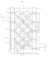
- the device 1 for static mixing and heat exchange consists of a jacket element 2 and a mixer insert 3, wherein the mixer insert 3 is arranged in the operating state in the interior of the jacket element 2.
- the mixer insert 3 has a longitudinal axis 4, which extends substantially in the main flow direction of the flowable medium, which flows through the jacket element 2 in the operating state.
- the mixer insert comprises a first group 5 of web elements and a second group 6 of web elements.
- the first group 15, the second group 16, the first group 25, the second group 26, the first group 35, the second group 36, and the first group 45 and the second group 46 are shown. Except for the group pairs 15, 16 and 45, 46 all group pairs are the same. Therefore, the following description applies to the first groups 5, 25, 35 and the second groups 6, 26, 36.
- Each group may comprise a plurality of web elements. Depending on the size of the mixing space 80 and / or the width of the web elements, 2 to 20, preferably 4 to 12, web elements of a group can be arranged parallel to one another.
- the length of a bar element is understood to mean the dimension from the first end 13 to the second end 14 of the bar element along its center axis.
- the thickness of the bar means the dimension normal to the center axis from one edge to the opposite edge.
- the width of the bar element is understood to be the dimension transverse to the longitudinal axis 4, that is to say the dimension which is shown in FIG Fig. 1 is normal to the drawing plane.
- the first group 5 of web elements extends along a common first group plane 7.
- the group plane 7 contains the longitudinal axis of a channel 11 running inside the web element 9, when the channel is arranged such that its longitudinal axis coincides with the center axis of the web element.
- the group level 7 is normal to the plane of the drawing.
- the second group 6 of web elements extends along a second common group plane 8.
- the group plane 8 is defined in the same way as the group plane 7.
- the first and second group planes 6, 7 intersect. In the present representation, they intersect exactly on the longitudinal axis 4 of the mixer insert.
- a web element 9 of the first group adjoins a web element 10 of the second group.
- the web element 9 is thus arranged crosswise to the web element 10.
- the web elements of the first group thus alternate with the web elements of the second group.
- the web element 9 is cut along its longitudinal axis, so that one half of the channel 11 is visible.
- the web element 10 is located with respect to the plane of the drawing behind the web element 9. It is therefore not cut and the running through the web element 10 channel 12 is shown only by a dashed line.
- the channel 11 of the post member 9 of the first group extends from a first end 13 to a second end 14 of the post member.
- the channel 11, 12 may have a cross-sectional area in the form of a round element.
- the round element is available from the group of circles, ellipses, rounded squares or polygons.
- the mixer insert and the jacket element 2 according to Fig. 1 are manufactured as a monolithic structure in the casting process.
- the jacket element 2 is constructed from a jacket body 51 which contains an inlet connection 52 and a discharge connection 53 for a heat transfer fluid.
- the sheath body includes a distribution channel 64 for distributing the heat transfer fluid to a plurality of supply channels and a collection channel 65 for the merger of the heat transfer fluid from a plurality of discharge channels. For example, each one inlet channel 54 and a discharge channel 55 with the first and second end 13, 14 of the rod member in fluid communication.
- a feed channel 56, 58, 60 is provided, which supplies the heat transfer fluid to the corresponding channel in the web element and a channel 57, 59 which directs the heat transfer fluid from the channel in the web element in the collecting channel 65 of the sheath body 51.
- a feed channel 56, 58, 60 is provided, which supplies the heat transfer fluid to the corresponding channel in the web element and a channel 57, 59 which directs the heat transfer fluid from the channel in the web element in the collecting channel 65 of the sheath body 51.
- Fig. 1 the web elements 9, 29, 39, 49 are shown cut, the web elements 10, 20, 30, 40, 50 are in the drawing plane behind it. The channels in these web elements are not visible, they are therefore not designated.
- the transition from at least one of the first and second ends 13, 14 of the rod member 11 to the respective corresponding channel 54, 55 in the jacket body 51 of the jacket member 2 is effected gap-free.
- the web elements of the mixer insert 3 and the jacket element 2 accordingly consist of a single component, which is preferably produced by a casting process.
- the method for producing a device 1 for mixing and heat exchange as shown in Fig. 1 is shown, which contains a mixer insert 3 and a jacket element 2, takes place at least in segments as a monolithic structure in the casting process.
- the monolithic structure comprises a first and second group 5.6 of web elements 9, 10 fixed opposite the fluid flow direction at a non-zero angle and a jacket element 2 firmly connected to at least a part of the web elements.
- the web elements 9, 10 have channels 11, 12. These channels are flowed through in the operating state of a heat transfer fluid, which is not in connection with the flowable medium, which flows around the web elements.
- a casting mold is produced by means of a wax body, a ceramic shell is applied to the wax body, and then the wax is removed and the ceramic shell is produced by a firing process so that the ceramic shell can be filled with castable material.
- the pourable material is solidified by cooling and the ceramic shell removed after the solidification of the castable material.
- FIG. 5 is an enlargement of the area around the second end 14 of the web element 9. All other ends are advantageously designed with similar curves.
- a curve 91 is shown, which forms the transition from an upper edge or edge surface of the stalk element 9 to the inside of the sheath body 51 of the sheath element.
- a rounding 94 forms the transition from the lower edge or lower edge surface of the web element 9 to the inside of the shell body 51 of the shell element.
- the transition from the channel 54 to the channel 11 also takes place via a rounded section.
- a convex curve 92 and an opposite concave curve 93 are shown in section.
- Each of the curves 91, 92, 93, 94 may in particular have a radius of at least 0.5 mm.
- any number of groups of web elements in the fluid flow direction can be arranged one behind the other.
- a plurality of first sub-groups 25, 35 are shown in addition to the first group 5.
- Group 5 was described as representative of the first subgroups 25, 35.
- the first subgroups 25, 35 have the same structure as the group 5 and therefore the description of the group 5 is also representative of the groups 25, 35.
- a plurality of subgroups 26, 36 are shown in addition to the second group 6.
- the second group 6 is also described as representative of the second subgroups 26, 36.
- the second subgroups 26, 36 have the same structure as the second group 6.
- Fig. 1 also shown a first subgroup 15 and a second subgroup 16, the web elements do not contain a channel. Thus, a part of the web elements can not contain a channel.
- the web element 19 of the first subgroup 15 extends only from the sheath body 51 to the longitudinal axis 4.
- the web element 20 of the second subgroup 16 also extends only from the sheath body 51 to the longitudinal axis 4.
- the two first and second group levels 17, 18 of the web elements 19, 20 intersect on the longitudinal axis 4.
- the first subgroup 15 and the second subgroup 16 form a right-hand end of the mixer insert.
- the right-hand end is characterized by an end plane 70, which is a normal plane to the longitudinal axis and extends through the right-side end points of the web elements 19, 20. She makes that right side completion of the mixer insert.
- the mixer insert On the right side of the end plane 70 can connect another mixing insert.
- the mixer insert may comprise a first group of web elements and a second group of web elements, wherein the first group of web elements to the first group 5 is rotated by an angle between 80 and 100 degrees about the longitudinal axis and the second group of web elements to the first group. 6 rotated by an angle between 80 and 100 degrees about the longitudinal axis. This further mixing insert is not shown in the drawing.
- the subgroups forming the end of the mixer insert can also contain channels so that the heat exchange is additionally improved. Therefore, in Fig. 1 also, a first subset 45 and a second subset 46 shown, the web elements 49, 50 each include a channel 41, 42. The channels 41, 42 of adjacent web elements can be connected, so that the heat transfer fluid from the supply channel 60 passes to a discharge channel, which is arranged behind the discharge channel 57 and therefore is not visible in the illustration.
- the web element 49 of the first subgroup 45 extends only from the sheath body 51 to the longitudinal axis 4.
- the web element 50 of the second subgroup 46 also extends only from the sheath body 51 to the longitudinal axis 4.
- the two first and second group levels of the web elements 49, 50 intersect on the longitudinal axis 4.
- the first subgroup 45 and the second subgroup 46 form a in the representation of Fig. 1 left-side end of the mixer insert.
- the left-hand end is characterized by an end plane 71, which is a normal plane to the longitudinal axis 4 and extends through the left-side end points of the web elements 49, 50. It forms the left-side completion of the mixer insert.
- On the left side of the end plane 71 can connect another mixing insert.
- the group level 7 of the first group 5 intersects with the second group level 8 of the second group 6 such that a common crossing line 75 is formed, which has an intersection with the longitudinal axis 4 or substantially transverse to the longitudinal axis and / or in a normal plane to the intersection line, which contains the longitudinal axis, a minimum distance from the longitudinal axis.
- the web elements have a configuration which is symmetrical with respect to the cutting plane, so that the mixture in the sub-region of the mixing chamber 80 located above the longitudinal axis is essentially as good as in the sub-region of the mixing chamber located below the longitudinal axis.
- the mixer insert could consist only of a first group 5 and a second group 6. Therefore, in the description, the first group 5 and the second group 6 are considered to be representative of a plurality of other similar first or second groups. How many pairs of groups are provided for each case depends on the specific mixing and heat exchange task. That is, if in the following documents only the first and the second group are described, it can not be deduced that only this particular embodiment is disclosed, but rather embodiments with a plurality of pairs of groups, each of these groups of pairs of first and second a second group is to be covered by this description. For the sake of simplicity, the description is limited to one of the group pairs, a repetition of the description for the possible further group pairs 25, 35, 26, 36 is therefore omitted.
- the channels 11, 12 extend in the interior of the web elements 9, 10 extend, so that no connection between the channels in the interior of the web elements and the mixing chamber 80, which surrounds the web elements consists.
- the first and second group planes are arranged at an angle of 25 to 75 degrees to the longitudinal axis 4.
- the angle is 30 to 60 degrees to the longitudinal axis 4, in many cases substantially 45 degrees to the longitudinal axis. 4
- the groups arranged one behind the other are advantageously arranged so that they overlap in order to provide as much active heat exchange surface as possible in the volume formed by the jacket element 2.
- Overlapping means that at least a portion of the web members of a first group and a portion of the web members of a subsequent group and / or a portion of the web members of a preceding group are located in the same pipe section seen in the main fluid flow direction.
- the projection of the length of the bar element on the longitudinal axis gives a length L1 and the projection of the overlapping part of the bar elements of the adjacent group on the longitudinal axis results in a length L2, where L2 is smaller than L1 and L2 is greater than 0.
- the considered pipe section is defined so that it has the length L1, that is, the envelope volume of the centrally arranged web element 9 represents.
- the envelope volume is an enveloping cylinder in the case of a cylindrical jacket element with a circular cross section, and an envelope cuboid in the case of a jacket element with a rectangular or polygonal cross section.
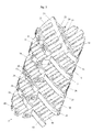
- Fig. 2 shows a three-dimensional sectional view through the device according to Fig.1 , Same parts will be in this Fig. 2 same name and no longer described, as far as the description already in connection with Fig. 1 has been made.
- Fig. 2 shows the belonging to the group 15 web elements 20, 21, 22, 23, 24th
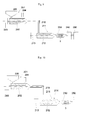
- Fig. 3 shows a view of the mixer insert for the device according to Fig. 1 ,
- the mixer insert 3 differs from Fig. 1 only in that the groups 45, 46 do not contain any channels.
- Fig. 4 shows a three-dimensional sectional view of a device according to a second embodiment, in which a first mixer insert 3 and a second mixer insert 103 in a first shell element 2 and a second shell element 102 are arranged one behind the other.
- the first jacket element 2 and the first mixer insert 3 are rotated at an angle of 90 degrees with respect to the second jacket element 102 and the second mixer insert 103.
- Fig. 6 shows a two-dimensional sectional image of a third embodiment of an inventive device.
- the device 1 consists of a jacket element 2 and a mixer insert 3, which have a common longitudinal axis 4.
- first group 5 and a second group 6 of web elements extend.
- the groups are arranged along a first group level 7 and a second group level 8.
- a web element 9 of the first group is shown in section, as well as a web element 10 of the second group.
- the first and second group planes are essentially parallel to one another.
- the web elements that would end in the end plane 71 may be connected to a collection element 155.
- the collecting element 155 may have a collecting channel 157.
- the web elements which begin in the end plane 70 may be connected to a distribution element 156.
- the distribution element 156 may include a distribution channel 158.
- the heat transfer fluid is fed via the inlet connection to a distribution channel 64 located in the jacket element 2. From the distribution channel 64, the heat transfer fluid passes through the supply channels 54, 56, 58, 60, 62, 154 and via the distribution channel 158 in the channels of the web elements.
- the heat transfer fluid passes after the flow through the channels of the web elements in the collecting channel 157 and in the discharge channels 57, 59, 61, 63, 159, 161, 163, 165, 167. From the discharge channels, the heat transfer fluid enters the collecting channel 65 and is on the Drain port 53 removed. The flowable medium flows around the web elements in the mixing chamber 80.
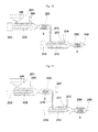
- Fig. 7 shows a two-dimensional sectional image of a fourth embodiment of an inventive device.
- This sectional view shows that the arrangement of the web elements can be done at any angle.
- a first web element 9 of a first group 5 and a second web element 10 of a second group 6 are shown.
- a plurality of similar or different web elements 9 can be arranged along the first group plane 7.
- the arranged behind the web element 9 web elements of this group are not visible in the present illustration.
- the angle which the illustrated section line of the first group plane 7 encloses in the plane of the drawing with the longitudinal axis 4 differs from the angle which the illustrated section line of the second group plane 8 encloses in the plane of the drawing with the longitudinal axis 4.
- the web widths of the web elements of the first group 5 may differ from the web widths of the web elements of the second group 6.
- Adjacent groups may optionally have parallel group planes or may include different angles to the longitudinal axis 4.
- a subgroup 15 is shown whose group plane 17 runs parallel to the group plane 8.
- a further subgroup 25 is shown, whose group plane 27 does not run parallel to the group plane 8, but encloses a smaller angle with the longitudinal axis 4.
- more than two groups can intersect and can also be interconnected via common connecting elements.
- the group 5 can be connected, for example, to the subgroup 15 and the subgroup 35 via common connection elements.
- the connecting elements are not shown; they may, for example, be transverse webs which run normal to the plane of the drawing and, for example, connect group 5 and subgroup 15 in the region of the crossing point.
- the subgroup 15 may be connected to the subgroup 35.
- the subgroup 16 includes a web element 20 which has two web element sections 31, 32.
- the two web element sections 31, 32 enclose an angle to one another. It would also be possible for the first web element section and the second web element section are connected to each other via a curved portion, this variant is not shown in the drawing.
- Fig. 8 shows a view of a device according to a fifth embodiment.
- the device 1 consists of a mixer insert 3 and a jacket element 2.
- This mixer insert 3 is installed in a jacket element 2 with a quadrangular cross-sectional area. Other cross-sectional areas are possible, for example circular cross-sectional areas.
- the present illustration shows a first group 5 and a second group 6 of web elements.
- the web elements 9, 19 of the first group 5 are similar and arranged parallel to each other.
- the web elements 10, 20 of the second group 6 are similar and arranged parallel to each other.
- the web elements 9, 19 form an angle with the web elements 10, 20. That is, according to this variant, adjacent web elements are at least partially belonging to the same group.
- a first subgroup 15 and a second subgroup 16 are arranged downstream of the first group 5 and the second group 6, Downstream of the first group 5 and the second group 6, a first subgroup 15 and a second subgroup 16 are arranged.
- the web elements of the subgroups 15, 16 are rotated about the longitudinal axis 5 by an angle of 90 degrees, based on the web elements of the first and second groups 5, 6.
- the mixer insert 3 includes a further subgroup 25 and a further subgroup 26. These two subgroups 25, 26 are mirrored with respect to the groups 5, 6 about a normal plane of the longitudinal axis 4.
- Fig. 8 also the channels are shown, which run in the web elements.
- the channel 11 of the rod member 9 has oval or circular cross-section.
- the channels may also have other cross-sectional areas. Through the casting process, a variety of different cross-sectional areas can be used.
- the web element 29 shows, for example, a channel 31 with a quadrangular cross-sectional area. Triangular or polygonal cross-sectional areas can be realized in the same way.
- the jacket element 2 is only partially shown.
- the jacket element 2 includes an inlet nozzle 52 and a distribution channel 64, which is partially shown.
- the distribution channel 64 is in communication with a part of the channels in the Web elements. Through the distribution channel 64, a heat transfer fluid, which is supplied via the inlet nozzle, are distributed to the channels of the web elements. Not shown is an associated collection channel, which is connected to another part of the channels in the web elements.
- the distribution channel each opposite ends of the web elements open into the collection channel. From the collecting channel, the heat transfer fluid passes into the drain port and can leave the device 1 via this drain port.
- Fig. 9 shows a first variant of an extrusion assembly with a mixer insert according to one of the preceding embodiments.
- This extrusion arrangement consists of a first extruder 201, a second extruder 211 of a transfer line, which connects the first extruder 201 to the second extruder 211, and a nozzle element 240, through which the plastic melt leaves the extrusion arrangement.
- a process for producing low-density foams can be carried out.
- a plastic in the first extruder 201 is melted into a plastic melt, the plastic melt is added a blowing agent via amaschineschzugabevorraum 204, then the blowing agent in the melt by mixing and dispersing operations in the first extruder 201 and / or one of a static mixer 220 formed static Mixing line or a transfer line 215 between the first and a second extruder 211 and / or dissolved in the second extruder 211, then the propellant laden melt in the second extruder 211 is cooled, then the melt is passed through a static mixer 230, wherein the static Mixer has a mixer insert 3, by means of which the temperature of the melt is homogenized over the entire cross-section and can be cooled or heated simultaneously in order to achieve an exact melt temperature. Thereafter, the temperature-stabilized cooled melt is discharged via a nozzle element 240, 250.
- the mixer insert on mounting elements which engage in the melt and over which the melt can be cooled or heated.
- the temperature of the melt is advantageously homogenized such that the lowest and highest temperature in the melt cross-section after the mixer use by less than 5 degrees Celsius apart.
- the temperature can be homogenized so far that the lowest and highest temperature in the melt cross-section after mixing use are less than 3 degrees Celsius apart, more preferably less than 1.5 degrees Celsius apart.
- the mixer insert 3 comprises a first group 5 of web elements and a second group 6 of web elements, the first group 5 of web elements extending along a common first group plane 7 and the second group 6 of web elements extending along a second common group plane 8 extends.
- the melt temperature can be controlled by the mixer insert on the cool and heatable mixer insert 3.
- melt temperature after mixer use the temperature prevailing in the melt after its exit from the static mixer 230 is understood, for example, shortly before the nozzle element or in the nozzle element.
- the nozzle element after the mixer insert for example, as a nozzle 240, as well as in Fig. 11 shown, or as a granulator 250 as in Fig. 10 shown to be trained.
- a cooling device 260 may be provided, in which the extrudate is further cooled to solidification.
- the propellant may be added by means of a propellant addition device 204 and / or via the plastic raw material addition in the feed container 205, which is arranged on the first extruder 201. Additionally or alternatively, the propellant may also be added via a propellant addition device 214 disposed on the second extruder 211, which is shown in FIG Fig. 10 or Fig. 11 or via an adding device which is mounted in the transfer line 215.
- the blowing agent may be added to the melt in at least one of the first or second extruders.
- Fig. 10 shows a second variant of an extrusion assembly with a mixer insert according to one of the preceding embodiments, according to which the nozzle element, a granulator 250 is connected downstream.
- melt is crushed by means of cutting elements.
- the melt is solidified by being cooled.
- the melt is guided, for example, through a coolant bath.
- Fig. 11 shows a third variant of an extrusion assembly with a mixer insert 3 according to one of the preceding embodiments.
- This extrusion arrangement consists of a first extruder 201, a second extruder 211 of a static mixing section, which connects the first extruder 201 to the second extruder 211, and a nozzle element 240, through which the cooled plastic melt leaves the extrusion arrangement.
- the static mixing section contains a static mixer 220.
- a heat exchanger can be attached. It is also possible to use apparatuses in which the functions of a heat exchanger and a mixer are combined. In the present extrusion arrangement, a process for producing low-density foams can be carried out.
- a plastic in the first extruder 201 is melted into a plastic melt, the plastic melt is added a blowing agent via amaschineschzugabevoriques 204, then the blowing agent in the melt by mixing and dispersing operations in the first extruder 201 and formed by a static mixer 220 static mixing between first extruder 201 and a second extruder 211 and dissolved in the second extruder 211, and possibly also cooled when using a heat exchanger, Thereafter, the blowing agent-laden melt in the second extruder 211 is cooled.
- the melt is passed through a static mixer 230, the static mixer having a mixer insert 3, by means of which the temperature of the melt is homogenized over the entire cross section and can be cooled or heated simultaneously in order to achieve an exact melt temperature. Thereafter, the temperature-stabilized cooled melt is discharged via a nozzle 240.
- Fig. 12 is a variant of Fig. 11 which shows an additional blowing agent adding means 224 or other additives in the region of the transfer line 215.
- This blowing agent adding device may be used in conjunction with the adding devices 104 and 214, and optionally, the addition of blowing agents or additives in at most two of the three adding devices 204, 214, 224 may be omitted. That is, depending on the composition of the plastic melt and / or their desired mechanical properties, one or more addition devices may be used.
- the invention is not limited to the present embodiments of the mixer inserts.
- the web elements can differ in their number and in their dimensions. Instead of web elements pipe elements or planar elements, such as wing elements may be provided. Furthermore, the number of channels in the web elements may differ depending on the required heat requirement for the heat transfer. Also, the angles of inclination which the groups include to the longitudinal axis may vary depending on the application. It can also be arranged more than two mixer inserts in a row.
Abstract
Ein Verfahren zur Herstellung von niederdichten Schäumen umfasst die nachfolgenden Schritte. Ein Kunststoff wird in einem ersten Extruder (201) zu einer Kunststoffschmelze aufgeschmolzen, der Kunststoffschmelze wird ein Treibmittel zugegeben, wodurch eine mit Treibmittel beladene Schmelze erhalten wird, die einem zweiten Extruder (211) zugeführt wird. Danach wird die mit Treibmittel beladene Schmelze in dem zweiten Extruder (211) gekühlt, danach die Schmelze durch einen statischen Mischer (230) geführt, wobei der statische Mischer einen Mischereinsatz (3) aufweist, mittels welchem die Temperatur der Schmelze über den ganzen Querschnitt homogenisiert wird und der gekühlt oder beheizt werden kann, um eine temperaturstabilisierte gekühlte Schmelze zu erhalten. Danach wird die temperaturstabilisierte gekühlte Schmelze über ein Düsenelement (240, 250) ausgetragen.

Description
Die Erfindung betrifft ein Verfahren zur Herstellung von niederdichten Kunststoffschäumen. Als niederdichte Kunststoffschäume werden Kunststoffschäume mit einer Dichte von weniger als 500 kg/m3 angesehen. Dabei wird der Kunststoff in einem ersten Extruder aufgeschmolzen, zudem wird der Kunststoffschmelze ein Treibmittel zugegeben, danach wird das Treibmittel in der Schmelze durch Misch-und Dispergiervorgänge im ersten Extruder und/oder einer statischen Mischstrecke zwischen erstem und zweitem Extruder und/oder im zweiten Extruder gelöst, danach wird die mit Treibmittel beladene Schmelze in einem zweiten Extruder gekühlt, danach wird die Schmelze durch einen statischen Mischereinsatz geführt, mit dem die Temperatur der Schmelze über den ganzen Querschnitt homogenisiert wird und gleichzeitig gekühlt oder geheizt werden kann, um auf diese Weise eine exakte Schmelzetemperatur zu erreichen. Danach wird die temperaturstabilisierte gekühlte Schmelze über eine Düse ausgetragen und schäumt zu einem Extrudat auf, worauf das aufgeschäumte oder noch aufschäumende Extrudat bis zur Erstarrung weiter gekühlt wird. An die Düse kann auch ein Granulator und im speziellen ein Unterwassergranulator anschliessen. In diesem Falle erstarrt die mit Treibmittel beladene Schmelze ohne Aufschäumen. Das Aufschäumen erfolgt dann in einem Nachfolgeprozess.The invention relates to a process for the production of low-density plastic foams. As low-density plastic foams plastic foams are considered with a density of less than 500 kg / m 3 . In this case, the plastic is melted in a first extruder, also the plastic melt is added a blowing agent, then the blowing agent in the melt by mixing and dispersing in the first extruder and / or a static mixing section between the first and second extruder and / or in the second extruder after which the blowing agent-laden melt is cooled in a second extruder, then the melt is passed through a static mixer insert, with which the temperature of the melt is homogenized over the entire cross section and can be cooled or heated at the same time, in order to to achieve exact melt temperature. Thereafter, the temperature-stabilized cooled melt is discharged through a nozzle and foams to an extrudate, whereupon the foamed or still foaming extrudate is further cooled to solidification. To the nozzle can also connect a granulator and in particular an underwater granulator. In this case, the laden with blowing agent melt solidifies without foaming. The foaming then takes place in a subsequent process.
Es sind Verfahren zur Herstellung von niederdichten Schäumen bekannt, bei denen das Kunststoffgranulat in einer ersten Stufe eines ersten Extruders aufgeschmolzen wird. Der entstehenden Schmelze wird in einer zweiten Stufe des ersten Extruders ein gasförmiges oder flüssiges Treibmittel zugegeben und eingelöst. Im Anschluss wird die mit Treibmittel beladene Schmelze über eine Transferleitung in einen zweiten Extruder geleitet, wobei die Schmelze in diesem zweiten Extruder gekühlt wird. Die den zweiten Extruder verlassende Schmelze wird durch einen statischen Mischer geführt. Ein derartiger statischer Mischer kann als rohrförmiger Hohlkörper ausgebildet sein, in dessen Innenraum ortsfeste Einbauten angeordnet sind, welche als Mischereinsätze ausgebildet sind. Der rohrförmige Hohlkörper hat in der Regel einen kreisförmigen Querschnitt. Durch die Einbauten wird die Strömung gestört, wodurch es zu einer Durchmischung kommt. In der Regel tritt die Schmelze in den statischen Mischer mit einem Temperaturgradienten ein. Die Kerntemperatur der Schmelze entspricht nicht der Wandtemperatur an der Innenwand des rohrförmigen Hohlkörpers. Durch die Mischvorgänge im Innenraum des statischen Mischers wird die Temperatur der Schmelze über den ganzen Querschnitt vergleichmässigt. Danach wird die Schmelze über eine Düse ausgetragen und schäumt auf. Daraufhin wird das aufgeschäumte oder noch aufschäumende Extrudat bis zur Erstarrung weiter gekühlt.Processes for the production of low-density foams are known in which the plastic granulate is melted in a first stage of a first extruder. The resulting melt is added in a second stage of the first extruder, a gaseous or liquid propellant and redeemed. Subsequently, the blowing agent-laden melt is passed via a transfer line in a second extruder, wherein the melt is cooled in this second extruder. The melt leaving the second extruder is passed through a static mixer. Such a static mixer may be formed as a tubular hollow body, in the interior of which fixed installations are arranged, which are designed as mixer inserts. The tubular hollow body usually has a circular cross-section. Due to the internals the flow is disturbed, resulting in a thorough mixing. As a rule, the melt enters the static mixer with a temperature gradient. The core temperature of the melt does not correspond to the wall temperature on the inner wall of the tubular hollow body. By the mixing processes in the interior of the static mixer, the temperature of the melt over the entire cross section is made uniform. Thereafter, the melt is discharged through a nozzle and foams up. Thereafter, the foamed or still foaming extrudate is further cooled until solidification.
Gemäss
Es ist auch bekannt, dass statische und dynamische Kühler in die Transferleitung zwischen den ersten und den zweiten Extruder eingebaut werden, um so die Kühlleistung des zweiten Extruders zu erhöhen. Des Weiteren ist es bekannt, statische Mischer in die Transferleitung einzubauen. Aus der
Aus der
Aus der
Es hat sich gezeigt, dass mit den bekannten Verfahren nicht immer eine zufriedenstellende, konstante Schaumqualität erreicht werden kann. Unter guter Schaumqualität werden Schaumprodukte verstanden, die sich zum Beispiel durch hohe mechanische Reiss- oder Druckfestigkeiten, geringe Dichten oder hohe Isolationswerte ausweisen. Diese Werte werden durch die Zellstruktur des Schaumproduktes beeinflusst. Vielfach sind eine enge Zellgrössenverteilung, möglichst kleine Zellgrössen und möglichst viele Zellen pro Volumen mit möglichst dünnen Zellwänden für gute Schaumqualitäten wichtig. Es sollten zudem sowohl über die Zeit wie auch im ganzen Produktquerschnitt möglichst gleichbleibende Zellstrukturen erreicht werden.It has been found that with the known methods, a satisfactory, constant foam quality can not always be achieved. Good foam quality is understood to mean foam products which are characterized, for example, by high mechanical tear or compressive strengths, low densities or high insulation values. These values are influenced by the cell structure of the foam product. In many cases, a narrow cell size distribution, the smallest possible cell sizes and as many cells per volume as possible with cell walls as thin as possible for good foam qualities are important. In addition, as constant as possible cell structures should be achieved both over time and throughout the product cross section.
Es ist zwar eine Vielzahl von statischen Mischern bekannt, allerdings weisen diese vorbekannten Mischer eine Reihe von Nachteilen auf, sodass bei deren Einsatz nicht die gewünschte Schaumqualität erhältlich ist. Beispielsweise wird in der
Eine Variante eines derartigen statischen Mischers wird in der
Das Dokument
Aufgabe der Erfindung ist es, das Verfahren zur Herstellung eines niederdichten Schaums zu optimieren, um konstante gute Schaumqualitäten zu erhalten, das heisst insbesondere einen Schaum mit homogenen physikalischen Eigenschaften, welche in verbesserten mechanischen Eigenschaften, wie Festigkeit, Zähigkeit oder Formbeständigkeit und / oder erhöhten Wärmeisolationswerten und oder geringerer Schaumdichte resultieren.The object of the invention is to optimize the process for producing a low-density foam in order to obtain constant good foam qualities, that is, in particular a foam with homogeneous physical properties, which in improved mechanical properties, such as strength, toughness or dimensional stability and / or increased thermal insulation values and or lower foam density.
Hierzu wird ein Verfahren zur Herstellung von niederdichten Schäumen vorgeschlagen, bei welchem ein Kunststoff in einem ersten Extruder zu einer Kunststoffschmelze aufgeschmolzen wird, die Kunststoffschmelze einem zweiten Extruder zugeführt wird, der Kunststoffschmelze ein Treibmittel zugegeben wird, wodurch eine mit Treibmittel beladene Schmelze erhalten wird, , danach die mit Treibmittel beladene Schmelze in dem zweiten Extruder gekühlt wird, die Schmelze nach Verlassen des zweiten Extruders durch einen statischen Mischer geführt wird, wobei der statische Mischer einen Mischereinsatz aufweist, wobei der Mischereinsatz Einbauelemente aufweist, die in die Schmelze eingreifen, sodass die Temperatur der Schmelze über den ganzen Querschnitt des Mischereinsatzes homogenisiert wird, wobei der statische Mischer gekühlt und/oder beheizt werden kann, um eine temperaturstabilisierte gekühlte Schmelze zu erhalten, danach die temperaturstabilisierte gekühlte Schmelze über ein Düsenelement ausgetragen wird. Unter temperaturstabilisierter Schmelze wird hierbei eine Schmelze verstanden, die eine gleichmässige Temperatur über den Schmelzequerschnitt gemessen aufweist. Zumindest eines der Einbauelemente kann einen Kanal enthalten, welcher von einem Wärmeträgerfluid durchströmt wird. Das Treibmittel kann der Kunststoffschmelze im ersten Extruder und/oder im zweiten Extruder und/oder in der Transferleitung zwischen dem ersten und zweiten Extruder zugegeben werden.For this purpose, a method for producing low-density foams is proposed, in which a plastic is melted in a first extruder to a plastic melt, the plastic melt is fed to a second extruder, the plastic melt is added to a blowing agent, whereby a blowing agent-laden melt is obtained, thereafter cooling the propellant-laden melt in the second extruder, passing the melt through a static mixer after exiting the second extruder, the static mixer having a mixer insert, the mixer insert having built-in elements which engage the melt so that the temperature the melt is homogenized over the entire cross section of the mixer insert, wherein the static mixer can be cooled and / or heated to obtain a temperature-stabilized cooled melt, then the temperature-stabilized cooled melt is discharged via a nozzle element. In this case, temperature-stabilized melt is understood as meaning a melt which has a uniform temperature measured over the melt cross-section. At least one of the mounting elements may include a channel, which is flowed through by a heat transfer fluid. The blowing agent can be added to the plastic melt in the first extruder and / or in the second extruder and / or in the transfer line between the first and second extruder.
Das Treibmittel kann in der Schmelze durch Misch- und Dispergiervorgänge im ersten Extruder und/oder einem statischen Mischer und/oder einer Transferleitung zwischen erstem und dem zweitem Extruder und/oder im zweiten Extruder gelöst werden.The blowing agent can be dissolved in the melt by mixing and dispersing operations in the first extruder and / or a static mixer and / or a transfer line between the first and the second extruder and / or in the second extruder.
Es hat sich gezeigt, dass zum Erreichen einer guten Schaumqualität neben der Temperaturhomogenisierung der Schmelze vor der Düse auch eine exakte Temperaturführung entscheidend ist, zudem muss die Schmelzetemperatur, das heisst die Temperatur der Schmelze zum Erreichen von sehr niederen Schaumdichten vielfach sehr tief gehalten werden. Mit den gemäss Stand der Technik eingesetzten statischen Mischern nach dem zweiten Extruder können zwar die Temperaturinhomogenitäten, die typischerweise nach dem zweiten Extruder vorhanden sind, ausgeglichen werden. Die statischen Mischer eignen sich aber nicht zur Beeinflussung der Temperatur, da mit ihnen nicht effizient gekühlt oder geheizt werden kann. Zudem bewirkt der Einsatz von statischen Mischern in vielen Fällen einen Temperaturanstieg der Schmelze bedingt durch den Druckverlust im Mischer. Der hierdurch verursachte Staudruck wird auf den zweiten Extruder ausgeübt und durch entsprechend höhere Friktion im Extruder kompensiert. Friktion führt zur Erzeugung von Wärme, was einen Temperaturanstieg der Schmelze zur Folge hat. Ein Temperaturanstieg der Schmelze ist aber in vielen Fällen unerwünscht, da dadurch niedrige Schaumdichten nicht erreicht werden können. Unter einem Schaum mit einer niedrigen Schaumdichte wird ein Schaum mit einer Dichte von weniger als 50%, vorzugsweise weniger als 20%, besonders bevorzugt weniger als 10% bezogen auf die Dichte einer ungeschäumten Polymerschmelze verstanden.It has been shown that to achieve a good foam quality in addition to the temperature homogenization of the melt in front of the nozzle and an accurate temperature control is crucial, also the melt temperature, that is, the temperature of the melt to achieve very low foam densities often very low. Although the static mixers used according to the prior art after the second extruder, the temperature inhomogeneities that are typically present after the second extruder, can be compensated. The static mixers are not suitable for influencing the temperature, since they can not be efficiently cooled or heated. In addition, the use of static mixers in many cases causes a temperature increase of the melt due to the pressure drop in the mixer. The resulting dynamic pressure is exerted on the second extruder and compensated by correspondingly higher friction in the extruder. Friction leads to the generation of heat, which results in a temperature rise of the melt. However, a temperature rise of the melt is undesirable in many cases, since low foam densities can not be achieved thereby. Under a foam with a low foam density is a foam with a density of less than 50%, preferably less than 20%, particularly preferably less than 10%, based on the density of an unfoamed polymer melt.
Eine exakte Temperaturführung im Austritt des zweiten Extruders ist vielfach sehr schwierig, da die Schmelze im zweiten Extruder mit hohen treibenden Temperaturdifferenzen um typischerweise 20 bis über 80 Grad Celsius gekühlt werden muss. Entsprechend ist eine Regelung der Austrittstemperatur im Bereich von plus / minus 1 bis 4 Grad Celsius sehr schwierig. Dazu ist auch noch zu berücksichtigen, dass die Schmelzetemperatur im Austritt vom zweiten Extruder über den Querschnitt gesehen vielfach sehr inhomogen ist. Die Temperaturunterschiede zwischen einer wandnahen Zone der Polymerschmelze und einem zentralen Bereich können bis zu 30 Grad Celsius betragen. Unter einem zentralen Bereich wird ein Bereich verstanden, der einem rotationssymmetrischen Körper entspricht, der um die Mittenachse des Extruders angeordnet ist und sich bis zu einem Drittel des Abstands zwischen Mittenachse und Innenwand des Extruders oder des statischen Mischers erstreckt.An exact temperature control in the outlet of the second extruder is often very difficult, since the melt in the second extruder with high driving temperature differences must be cooled by typically 20 to over 80 degrees Celsius. Accordingly, regulation of the outlet temperature in the range of plus /
Zudem können Veränderungen im Prozess zum Beispiel die Bildung von Ablagerungen im zweiten Extruder oder die Veränderung der Qualität vom eingesetzten Kunststoffrohmaterial zu zeitlichen Veränderungen des Temperaturprofils führen. Sowohl die durch die statischen Mischer verursachten Temperaturveränderungen wie auch die zeitlichen prozessbedingten Temperaturveränderungen können mit dem Verfahren gemäss Stand der Technik nicht mehr kompensiert werden und führen vielfach zu schlechten und oder sich verändernden Schaumqualitäten.In addition, changes in the process, for example, the formation of deposits in the second extruder or the change in the quality of the plastic raw material used can lead to temporal changes in the temperature profile. Both the temperature changes caused by the static mixers and the temporal process-related temperature changes can no longer be compensated with the prior art method and often lead to poor and / or changing foam qualities.
Daher wurde in der
Die erfindungsgemässe Optimierung des Prozesses besteht darin, dass die Schmelze nach dem zweiten Extruder durch einen statischen Mischereinsatz geführt wird, mit dem gleichzeitig gekühlt oder geheizt werden kann. Der Begriff Schmelzestrom kann synonym für Schmelze verwendet werden. Durch den Mischereinsatz nach dem zweiten Extruder wird die Temperatur über den ganzen Querschnitt ausgeglichen. Der Mischereinsatz weist insbesondere Einbauelemente auf, die in die Schmelze, insbesondere Kunststoffschmelze eingreifen. Zusätzlich kann die Schmelze über die Einbauelemente gekühlt oder beheizt werden. Der statische Mischereinsatz ist gemäss dieses Ausführungsbeispiels mit Einbauelementen ausgestattet, welche zumindest teilweise einen Kanal enthalten können, durch welchen ein Wärmeträgerfluid strömen kann. Das Wärmeträgerfluid ist durch die Kanalwände von der Schmelze getrennt, das heisst, das Wärmeträgerfluid kommt nicht mit der Schmelze in Kontakt. Es kann eine homogene Schmelzetemperatur erreicht werden, was bedeutet, dass die kälteste, niedrigste und heisseste, höchste Temperatur im Schmelzequerschnitt nach dem Mischereinsatz weniger als 5 Grad respektive weniger als 3 Grad respektive weniger als 1.5 Grad auseinander liegen. Der statische Mischereinsatz kann zudem gleichzeitig über ein Wärmeträgermedium gekühlt oder erwärmt werden, um so die Schmelze auf die optimale Verarbeitungstemperatur zu bringen. Diese Temperierung kann zum Beispiel von aussen über einen Doppelmantel erfolgen, der mit dem Wärmeträgermedium durchströmt wird. Als Wärmeträgermedium sind zum Beispiel Flüssigkeiten wie Wasser oder Öle geeignet. Es können aber auch andere Flüssigkeiten oder Gase wie Luft eingesetzt werden. Es hat sich aber gezeigt, dass speziell bei höheren Schmelzedurchsätzen von mindestens 50 kg/h eine Temperierung von aussen nur eine bedingte Wirksamkeit aufweist, da die Temperieroberfläche im Verhältnis zum Mischervolumen zu klein ist. Bei grösseren Schmelzedurchsätzen wird das Wärmeträgermedium daher bevorzugt über Einbauten geleitet, die in den Schmelzestrom eingreifen, um die Temperieroberfläche zu erhöhen. Der Mischereinsatz und die Einbauten für das Wärmeträgermedium werden bevorzugt so angeordnet, dass die Schmelze nicht in Teilströme aufgeteilt wird, sondern als Ganzes kontinuierlich über den ganzen Querschnitt gemischt wird. Der Mischereinsatz kann Einbauelemente in beliebiger Form enthalten. Die Einbauelemente können beispielsweise rohrförmige, stabförmige oder flächige, beispielsweise flügelartige Stegelemente umfassen.The inventive optimization of the process is that the melt is passed to the second extruder through a static mixer insert, can be cooled or heated at the same time. The term melt stream can be used synonymously for melt. The mixer insert after the second extruder compensates for the temperature over the entire cross section. The mixer insert has in particular installation elements which engage in the melt, in particular plastic melt. In addition, the melt can be cooled or heated via the installation elements. The static mixer insert is equipped according to this embodiment with built-in elements, which may at least partially contain a channel through which a heat transfer fluid can flow. The heat transfer fluid is separated by the channel walls of the melt, that is, the heat transfer fluid does not come into contact with the melt. It is possible to achieve a homogeneous melt temperature, which means that the coldest, lowest and hottest, highest melt cross-sectional temperatures are less than 5 degrees apart, less than 3 degrees, and less than 1.5 degrees, respectively, after mixer use. The static mixer insert can also be cooled or heated simultaneously via a heat transfer medium, so as to bring the melt to the optimum processing temperature. This tempering can be done, for example, from the outside via a double jacket, which is flowed through by the heat transfer medium. As a heat transfer medium, for example, liquids such as water or oils are suitable. But it can also be used other liquids or gases such as air. However, it has been shown that especially at higher melt throughputs of at least 50 kg / h, a temperature control from the outside has only a limited effectiveness, since the tempering surface is too small in relation to the mixer volume. For larger melt throughputs, the heat transfer medium is therefore preferred passed through internals, which engage in the melt stream to increase the temperature control surface. The mixer insert and the internals for the heat transfer medium are preferably arranged so that the melt is not divided into partial streams, but is mixed as a whole continuously over the entire cross section. The mixer insert may contain built-in elements in any form. The mounting elements may include, for example, tubular, rod-shaped or planar, for example, wing-like web elements.
Vorteilhafterweise kann bereits zwischen dem ersten und zweiten Extruder ein Temperaturausgleich und oder eine Vorkühlung der Schmelze erfolgen, wobei die Schmelze durch einen dynamischen Mischer, einen statischen Mischer, einen Wärmetauscher oder eine Transferleitung, die insbesondere als beheizbares oder kühlbares Rohrelement ausgebildet sein kann, oder durch eine Kombination von zumindest zwei der vorgenannten Vorrichtungen geführt wird.Advantageously, already between the first and second extruder, a temperature compensation and or a pre-cooling of the melt take place, wherein the melt through a dynamic mixer, a static mixer, a heat exchanger or a transfer line, which may be formed in particular as a heatable or coolable tubular element, or by a combination of at least two of the aforementioned devices is performed.
Zumindest ein Teil der Stegelemente kann eine Gruppe ausbilden. Eine derartige Gruppe kann beispielsweise derart gebildet werden, dass die Stegelemente je eine Mittenachse aufweisen. Die Mittenachsen der zu der Gruppe gehörigen Stegelemente schliessen einen im Wesentlichen konstanten Winkel zur Mittenachse des Mischereinsatzes ein.At least part of the web elements can form a group. Such a group can for example be formed such that the web elements each have a central axis. The center axes of the web elements belonging to the group include a substantially constant angle to the center axis of the mixer insert.
Es hat sich gezeigt, dass sich ein Mischereinsatz besonders gut eignet, der eine erste Gruppe von Stegelementen sowie eine zweite Gruppe von Stegelementen umfasst, wobei die erste Gruppe von Stegelementen sich entlang einer gemeinsamen ersten Gruppenebene erstreckt und die zweite Gruppe von Stegelementen sich entlang einer zweiten gemeinsamen Gruppenebene erstreckt. Solche Mischereinsätze können die Temperatur besonders gut über den ganzen Querschnitt ausgleichen. Als eingreifende Einbauelemente für die Schmelzetemperierung können beliebig geformte Einbauelemente verwendet werden, wie zum Beispiel Rohre oder Kanäle enthaltende Stegelemente die parallel zur Schmelzeflussrichtung angeordnet sind oder auch Einbauelemente, die in einem Winkel zur Schmelzeströmung angeordnet sind. Der Winkel zwischen der Mittenachse des Mischereinsatzes und der Mittenachse des Einbauelements kann insbesondere als spitzer Winkel oder als komplementärer stumpfer Winkel ausgebildet sein. Die Mittenachse des Mischereinsatzes entspricht der Hauptströmungsrichtung der Schmelzeströmung. Unter eingreifenden Einbauelementen sollen hiermit Einbauelemente verstanden werden, die in die Schmelze hineinragen. Ein derartiges Einbauelement ist daher ein die Strömung störender Körper, welcher der Schmelze lokal eine Richtungsänderung aufzwingt.It has been found that a mixer insert is particularly well suited, which comprises a first group of web elements and a second group of web elements, the first group of web elements extending along a common first group plane and the second group of web elements extending along a second common group level. Such mixer inserts can compensate the temperature particularly well over the entire cross section. As an intervening installation elements for the Schmelzetemperierung any shaped mounting elements can be used, such as tubes or channels containing web elements which are arranged parallel to the melt flow direction or also mounting elements which are arranged at an angle to the melt flow. The angle between the center axis of the mixer insert and the center axis of the mounting element may be formed in particular as an acute angle or as a complementary obtuse angle. The center axis of the mixer insert corresponds the main flow direction of the melt flow. By intervening mounting elements are hereby understood to be built-in elements which protrude into the melt. Such a mounting element is therefore a body disturbing the flow, which forces the melt locally to change direction.
Eine oder mehrere Gruppen von Stegelementen können mit dem Gehäusemantel verbunden sein oder aber auch als ausbaubarer Mischereinsatz im Gehäuse angeordnet sein. Es hat sich gezeigt, dass es besonders vorteilhaft ist, die eingreifenden Einbauelemente für die Schmelzetemperierung mit den im Mischereinsatz angeordneten Einbauelementen zu kombinieren. So können zum Beispiel zumindest zwei sich kreuzende Gruppen von Stegelementen oder Rohrelementen eingesetzt werden, durch die ein Wärmeträgermedium fliesst. Die sich kreuzenden Stegelement- oder Rohrelementgruppen sind über eine Kopfplatte gehalten und können aus dem sie umhüllenden Mischerrohr ausbaubar sein. Mit solchen Mischereinsätzen können sehr hohe Wärmeaustauschflächen realisiert werden. Mindestens ein Teil der Stegelemente kann Kanäle aufweisen, wobei die Kanäle sich von einem ersten Ende des Stegelements zu einem zweiten Ende des Stegelements erstrecken, wobei das Mantelelement je einen korrespondierenden Kanal enthält, der mit dem ersten Ende und zweiten Ende des Stegelements in fluidleitender Verbindung steht.One or more groups of web elements may be connected to the housing shell or arranged as a removable mixer insert in the housing. It has been found that it is particularly advantageous to combine the engaging installation elements for the melt temperature control with the installation elements arranged in the mixer insert. Thus, for example, at least two intersecting groups of web elements or pipe elements can be used, through which a heat transfer medium flows. The intersecting web element or pipe element groups are held by a top plate and can be removable from the mixer tube surrounding them. With such mixer inserts very high heat exchange surfaces can be realized. At least a portion of the web members may include channels, the channels extending from a first end of the web member to a second end of the web member, the shell member each including a corresponding channel in fluid communication with the first end and second end of the web member ,
Die Mischereinsätze können auch durch eine Mehrzahl von Rohrelementen gebildet werden, die sich von einem Eintrittsende des Mischers zu dessen Austrittsende erstrecken. Hierbei können sich der Anfang und das Ende des Rohrelements des Mischereinsatzes in derselben Kopfplatte befinden. Diese Kopfplatte ist mit dem Mischer, also dem Gehäuse, welches den Mischereinsatz umgibt, verbunden. Ein derartiges Rohrelement weist mindestens eine Umlenkung auf, die beispielsweise u-förmig ausgebildet sein kann. Zusätzlich zu dieser Umlenkung kann das Rohrelement weitere Umlenkungen aufweisen. Insbesondere kann ein derartiges Rohrelement derart ausgestaltet sein, dass die Umlenkungen im wandnahen Bereich angeordnet sind und sich zwischen benachbarten Umlenkungen gerade Rohrstücke erstrecken. Die geraden Rohrstücke können in einem spitzen Winkel zur Mittenachse des Mischers verlaufen, der Winkel kann insbesondere zwischen 10 Grad und 80 Grad liegen. Eine Mehrzahl derartiger Rohrelemente kann ein Rohrbündel ausbilden. Das Rohrbündel kann mehrere Gruppen von Rohrelementen enthalten, wobei die Rohrelemente derselben Gruppe im Wesentlichen parallel zueinander verlaufen. Die Gruppenebene wird durch die Mittenachsen der zu der entsprechenden Gruppe gehörigen Rohrelemente oder Stegelemente gebildet.The mixer inserts may also be formed by a plurality of tubular elements extending from an inlet end of the mixer to its outlet end. Here, the beginning and the end of the tubular element of the mixer insert can be located in the same top plate. This top plate is connected to the mixer, so the housing surrounding the mixer insert. Such a tubular element has at least one deflection, which may be formed, for example, U-shaped. In addition to this deflection, the pipe element may have further deflections. In particular, such a tubular element can be designed such that the deflections are arranged in the region near the wall and extend between adjacent deflections straight pipe sections. The straight pipe sections may extend at an acute angle to the center axis of the mixer, the angle may in particular between 10 degrees and 80 degrees lie. A plurality of such pipe elements can form a tube bundle. The tube bundle may contain a plurality of groups of tube elements, wherein the tube elements of the same group are substantially parallel to each other. The group plane is formed by the center axes of the pipe elements or web elements belonging to the corresponding group.
Es hat sich allerdings herausgestellt, dass der Mischeffekt eines primär als Wärmetauscher zum Einsatz kommenden derartigen Rohrbündels unter Umständen nicht zu optimalen Resultaten führt, da die sich ausdehnenden Rohre im Randbereich den Mischeffekt negativ beeinflussen. Ein derartiger Wärmetauscher ist beispielsweise in der
Besonders gut eignen sich Einbauelemente, bei dem der statische Mischereinsatz eine erste Gruppe von Stegelementen sowie eine zweite Gruppe von Stegelementen umfasst, wobei die erste Gruppe von Stegelementen sich entlang einer gemeinsamen ersten Gruppenebene erstreckt und die zweite Gruppe von Stegelementen sich entlang einer zweiten gemeinsamen Gruppenebene erstreckt. Mindestens ein Teil der Stegelemente weist Kanäle auf, wobei die Kanäle sich von einem ersten Ende des Stegelements zu einem zweiten Ende des Stegelements erstrecken. Das Mantelelement enthält je einen korrespondierenden Kanal, der mit dem ersten Ende und zweiten Ende des Stegelements in fluidleitender Verbindung steht. Solche temperierbaren Mischereinsätze zeichnen sich durch eine sehr gute Mischwirkung und gleichzeitig auch eine sehr hohe Kühlleistung respektive Heizleistung aus. Da der Mischereinsatz gleichzeitig auch die Temperierung übernimmt, sind keine zusätzlichen Einbauten wie zum Beispiel parallel zur Schmelzeströmung angeordnete Rohre für das Temperieren erforderlich, die den Mischprozess stören.Built-in elements are particularly well suited, in which the static mixer insert comprises a first group of web elements and a second group of web elements, the first group of web elements extending along a common first group plane and the second group of web elements extending along a second common group plane , At least a portion of the web members have channels, the channels extending from a first end of the web member to a second end of the web member. The jacket member each includes a corresponding channel which is in fluid communication with the first end and second end of the rod member. Such temperable mixer inserts are characterized by a very good mixing effect and at the same time also a very high cooling capacity or heat output. Since the mixer insert also takes over the temperature control, no additional internals such as arranged parallel to the melt flow tubes for tempering are required, which interfere with the mixing process.
Es hat sich gezeigt, dass durch den Einsatz vom erfindungsgemässen Mischereinsatz in Kombination mit dem beschriebenen Verfahren in vielen Fällen eine erstaunliche Verbesserung der Schaumstruktur erreicht werden kann. So können speziell Schäume mit sehr gleichmässigen Zellstrukturen, tiefer Schaumdichte und enger Zellgrössenverteilung erzielt werden. Dank der hervorragenden Zellstruktur sind auch die physikalischen Eigenschaften wie Reissfestigkeit, Zugfestigkeit oder der Isolationswert sehr gut. Auch kann eine eingestellte Schaumstruktur über die Zeit konstant gehalten werden, da unterschiedliche Temperaturbedingungen vom Extruder ausgeglichen werden können.It has been shown that in many cases an astonishing improvement in the foam structure can be achieved by using the mixer insert according to the invention in combination with the method described. So special Foams with very uniform cell structures, low foam density and narrow cell size distribution can be achieved. Thanks to the excellent cell structure, the physical properties such as tensile strength, tensile strength or the insulation value are also very good. Also, a set foam structure can be kept constant over time, since different temperature conditions can be compensated by the extruder.
Es hat sich ferner gezeigt, dass es sehr vorteilhaft ist, die Schmelzetemperatur über den kühl- und heizbaren Mischereinsatz zu regeln. Dabei wird vorteilhafterweise die Schmelzetemperatur nach dem Mischereinsatz zum Beispiel im Auslassbereich des Mischereinsatzes oder in der Düse gemessen und über Kühlen oder Heizen des Mischereinsatzes auf einer einstellbaren Solltemperatur gehalten. So kann eine bestimmte Temperatur auch bei sich ändernden Prozessbedingungen eingehalten werden, was für eine gleichbleibende Schaumqualität sehr wichtig ist.It has also been shown that it is very advantageous to control the melt temperature over the coolable and heatable mixer insert. In this case, the melt temperature is advantageously measured after the mixer insert, for example in the outlet of the mixer insert or in the nozzle and kept at an adjustable target temperature via cooling or heating of the mixer insert. Thus, a certain temperature can be maintained even with changing process conditions, which is very important for a consistent foam quality.
Eine über einen Querschnitt der Schmelze im Wesentlichen homogene Temperaturverteilung hat den Vorteil, dass die Zellgrössenverteilung über den ganzen Querschnitt des Extrudates vergleichmässigt wird. Bedingt durch die geringere Streuung der Zellgrösse in dem Querschnitt ergibt sich ein homogener Zellenaufbau, was zu einem Kunststoffkörper mit einem definierten Eigenschaftsprofil führt. Insbesondere weicht die mittlere Zellgrösse eines Breitenabschnittes von 20% der Gesamtbreite der extrudierten Folie oder Platte um weniger als 20% und vorzugsweise um weniger als 10% von den mittleren Zellgrössen eines jeden weiteren Breitenabschnittes ab. Bei der Herstellung von Platten und Folien zur thermischen Isolation beträgt der Anteil an offenen Zellen insbesondere weniger als 15%, vorzugsweise weniger als 10%, besonders bevorzugt weniger als 5% der gesamten Anzahl der Zellen.A substantially homogeneous temperature distribution over a cross section of the melt has the advantage that the cell size distribution over the entire cross section of the extrudate is made uniform. Due to the smaller scattering of the cell size in the cross section results in a homogeneous cell structure, resulting in a plastic body with a defined property profile. In particular, the average cell size of a width portion of 20% of the total width of the extruded sheet differs by less than 20% and preferably less than 10% from the average cell sizes of each further width portion. In the production of thermal insulation panels and films, the proportion of open cells is in particular less than 15%, preferably less than 10%, more preferably less than 5%, of the total number of cells.
Das erfindungsgemässe Verfahren kann für die Herstellung von niederdichten Schäumen aus allen Polymeren eingesetzt werden, es eignet sich aber speziell Polymere wie Polystyrol, Polypropylen, Polyethylen, Polyethylenterephthalat, Polyvinylchlorid, Polyacrylnitril, Polyamid, Polyester, Polyacrylat, Polymilchsäure (polylactic acid, PLA) und andere Biopolymere oder Mischungen davon. Als Treibmittel kommen beliebige Flüssigkeiten, Gase oder auch Feststoffe, die Gase abspalten oder Gemische von Treibmitteln zum Einsatz. Speziell eignen sich Ether, Kohlenwasserstoffe, Ketone, Ester, Wasser, Kohlendioxyd oder Stickstoff.The inventive method can be used for the production of low-density foams of all polymers, but it is especially suitable polymers such as polystyrene, polypropylene, polyethylene, polyethylene terephthalate, polyvinyl chloride, polyacrylonitrile, polyamide, polyester, polyacrylate, polylactic acid (PLA) and others Biopolymers or mixtures thereof. As propellants are any liquids, gases or solids, the gases split off or mixtures of blowing agents used. Especially suitable are ethers, hydrocarbons, ketones, esters, water, carbon dioxide or nitrogen.
Insbesondere kann das Düsenelement nach dem Mischereinsatz als Düse oder als Granulator ausgebildet sein. Anstelle der Verwendung einer Düse, bei der das Extrudat aufschäumt, kann somit auch ein Granulator und im speziellen ein Unterwassergranulator eingesetzt werden, mit dem die treibmittelbeladene Schmelze granuliert wird und erst später in einem Folgeprozess aufgeschäumt wird.In particular, the nozzle element may be designed after the mixer insert as a nozzle or as a granulator. Instead of using a nozzle, in which the extrudate foams, thus, a granulator and in particular an underwater pelletizer can be used, with which the propellant-laden melt is granulated and is foamed later in a subsequent process.
Eine Vorrichtung zum statischen Mischen und Wärmeaustausch umfasst ein Mantelelement und einen Mischereinsatz, wobei der Mischereinsatz im Betriebszustand im Inneren des Mantelelements angeordnet ist. Der Mischereinsatz hat eine Längsachse, die sich im Wesentlichen in Richtung der Strömung des fliessfähigen Mediums erstreckt. Die Richtung der Strömung wird nachfolgend als Hauptströmungsrichtung bezeichnet.A device for static mixing and heat exchange comprises a jacket element and a mixer insert, wherein the mixer insert is arranged in the operating state in the interior of the jacket element. The mixer insert has a longitudinal axis which extends substantially in the direction of the flow of the flowable medium. The direction of the flow is hereinafter referred to as the main flow direction.
Der Mischereinsatz umfasst eine erste Gruppe von Stegelementen sowie eine zweite Gruppe von Stegelementen, wobei die erste Gruppe von Stegelementen sich entlang einer gemeinsamen ersten Gruppenebene erstreckt und die zweite Gruppe von Stegelementen sich entlang einer zweiten gemeinsamen Gruppenebene erstreckt. Die Gruppenebene ist somit dadurch charakterisiert, dass sie die Mittenachse der Stegelemente enthält. Mindestens ein Teil der Stegelemente weist Kanäle auf, wobei die Kanäle sich von einem ersten Ende des Stegelements zu einem zweiten Ende des Stegelements erstrecken. Das Mantelelement enthält je einen korrespondierenden Kanal, der mit dem ersten und zweiten Ende des Stegelements in fluidleitender Verbindung steht, wobei der Übergang von zumindest einem der ersten und zweiten Enden des Stegelements zu dem jeweils korrespondierenden Kanal im Mantelelement spaltfrei erfolgt. Zumindest ein Teil der Stegelemente erstrecken sich somit über die gesamte Breitenabmessung oder den Durchmesser des Mantelelements. Die Kanäle in den Stegelementen erstrecken sich vom ersten Ende zum zweiten Ende des Stegelements, welches unmittelbar an die Innenwand des Mantelelements anschliesst. Im Mantelelement befindet sich ein Kanal, der an das Kanalende am jeweiligen Ende des Stegelements anschliesst. Die Stegelemente können somit vom Mantelelement mit einem Wärmeträgerfluid, insbesondere einer Wärmeträgerflüssigkeit, gespeist werden und von dem Wärmeträgerfluid durchströmt werden. Die Länge des Kanals ist grösser als der mittlere Durchmesser des Mantelelements, wenn das Stegelement die Längsachse enthält.The mixer insert comprises a first group of web elements and a second group of web elements, the first group of web elements extending along a common first group plane and the second group of web elements extending along a second common group plane. The group plane is thus characterized by containing the center axis of the web elements. At least a portion of the web members have channels, the channels extending from a first end of the web member to a second end of the web member. The jacket element in each case contains a corresponding channel, which is in fluid-conducting connection with the first and second ends of the rod element, wherein the transition from at least one of the first and second ends of the rod element to the respective corresponding channel in the jacket element is gap-free. At least a part of the web elements thus extend over the entire width dimension or the diameter of the jacket element. The channels in the web members extend from the first end to the second end of the web member, which immediately adjoins the inner wall of the jacket member. In the jacket element is a channel which connects to the channel end at the respective end of the bar element. The web elements can thus from the jacket element with a heat transfer fluid, in particular a Heat transfer fluid, are fed and flowed through by the heat transfer fluid. The length of the channel is greater than the average diameter of the jacket element when the bridge element contains the longitudinal axis.
Der mittlere Durchmesser entspricht dem Innendurchmesser, wenn das Mantelelement als ein Kreisrohr ausgeführt ist. Der mittlere Durchmesser für ein eckiges Mantelelement wird als dessen Umfang / n definiert, es handelt sich somit um einen äquivalenten Durchmesser. Die Länge des Kanals liegt mindestens 10% über dem mittleren Durchmesser, wenn der Kanal die Mittenachse kreuzt. Die Länge dieses Kanals liegt insbesondere mindestens 20% über dem mittleren Durchmesser, besonders bevorzugt mindestens 30% über dem mittleren Durchmesser.The mean diameter corresponds to the inner diameter when the jacket element is designed as a circular tube. The mean diameter for a square shell element is defined as its perimeter (s), which is an equivalent diameter. The length of the channel is at least 10% above the mean diameter when the channel crosses the center axis. The length of this channel is in particular at least 20% above the mean diameter, more preferably at least 30% above the mean diameter.
Ein Stegelement ist in seinen Abmessungen durch seine Länge, seine Breite und seine Dicke bestimmt. Die Länge des Stegelements wird vom ersten Ende des Stegelements zum zweiten Ende des Stegelements gemessen. Die Länge des Kanals entspricht im Wesentlichen der Länge des Stegelements.A web element is determined in its dimensions by its length, its width and its thickness. The length of the bar element is measured from the first end of the bar element to the second end of the bar element. The length of the channel essentially corresponds to the length of the bar element.
Die Breite des Stegelements wird im Wesentlichen quer zur Strömungsrichtung gemessen. Das heisst, die Breite erstreckt sich im Wesentlichen in einer Ebene, die normal zur Länge des Stegelements verläuft und den Querschnitt des Stegelements zeigt. Der Querschnitt des Stegelements wird durch dessen Breite und dessen Dicke charakterisiert. Die Länge zumindest des längsten Stegelements ist mindestens 5-mal so gross wie dessen Breite.The width of the bar element is measured essentially transversely to the flow direction. That is, the width extends substantially in a plane that is normal to the length of the bar element and shows the cross section of the bar element. The cross section of the bar element is characterized by its width and thickness. The length of at least the longest bar element is at least 5 times as large as its width.
Die Breite des Stegelements ist 0.5 bis 5-mal so gross wie dessen Dicke, vorteilhafterweise 0.75 bis 3-mal so gross wie dessen Dicke. Wenn die Breite des Stegelements 1 bis 2 mal so gross wie dessen Dicke ist, ergibt sich ein besonders bevorzugter Bereich, der eine besonders gute Quervermischung aufweist. Die Breite des Stegelements wird als Normalabstand definiert, welcher sich von der ersten Kante und der zweiten Kante des Stegelements erstreckt auf der Anströmseite. Die Breite des Stegelements auf der Anströmseite kann sich von der Breite gemessen auf der Abströmseite des Stegelements unterscheiden.The width of the bar element is 0.5 to 5 times as large as its thickness, advantageously 0.75 to 3 times as large as its thickness. If the width of the bar element is 1 to 2 times the thickness thereof, a particularly preferred range results, which has a particularly good cross-mixing. The width of the bar element is defined as the normal distance which extends from the first edge and the second edge of the bar element on the upstream side. The width of the stem element on the upstream side may differ from the width measured on the downstream side of the stem element.
Unter einer Kante wird die vom Fluid angeströmte und umströmte Kante des Stegelements verstanden, welche sich im Wesentlichen parallel zur Länge des Stegelements erstreckt. Die Dicke des Stegelements kann variabel sein. Dabei liegt die minimale Dicke, um weniger als 75% und vorteilhafterweise um weniger als 50% unter der maximalen Dicke. Die Variationen können beispielsweise durch Rippen, durch Einbuchtungen, durch Noppen, durch keilförmige Stege oder einer andere Unebenheit bedingt sein.An edge is understood as meaning the edge of the rod element which flows in and flows around the fluid, which edge extends substantially parallel to the length of the rod Steg elements extends. The thickness of the bar element can be variable. The minimum thickness is less than 75% and advantageously less than 50% below the maximum thickness. The variations may, for example, be due to ribs, indentations, nubs, wedge-shaped webs or other unevenness.
Das Stegelement ist dadurch charakterisiert, dass in der Strömungsrichtung ebene Flächen oder konkave Flächen vorliegen, die eine Angriffsfläche für das strömende Fluid bieten. Diese in Strömungsrichtung ausgerichteten Flächen bewirken, dass gegenüber einem Rohrelement ein erhöhter Abströmwiderstand entsteht. Es hat sich gezeigt, dass ein Rohrelement eine geringe Mischwirkung hat. Ein Rohrelement ist als Lösung in der
Der Kanal, der im Inneren des Stegelements verläuft, hat vorzugsweise einen Innendurchmesser, der maximal 75% der Dicke des Stegelements entspricht. Grundsätzlich können auch mehrere im Wesentlichen parallel verlaufende Kanäle in einem Steg angebracht sein.The channel, which runs in the interior of the bar element, preferably has an internal diameter which corresponds to a maximum of 75% of the thickness of the bar element. In principle, a plurality of substantially parallel channels can be mounted in a web.
Der Übergang von zumindest einem der ersten und zweiten Enden des Stegelements zu dem jeweils korrespondierenden Kanal im Mantelkörper des Mantelelements erfolgt spaltfrei. Die Stegelemente des Mischereinsatzes sowie das Mantelelement bestehen demnach aus einem einzigen Bauteil, welches vorzugsweise durch ein Giessverfahren hergestellt ist. Charakteristisch für die Eigenschaft, dass der Übergang spaltfrei ist, ist ein fliessender Übergang vom Stegelement zum Mantelelement. Insbesondere können im Übergangsbereich vom Stegelement zum Mantelelement an den Kanten Rundungen vorgesehen sein, sodass der Fluss des giessfähigen Materials während des Herstellungsverfahrens nicht beeinträchtigt wird.The transition from at least one of the first and second ends of the rod element to the respective corresponding channel in the jacket body of the jacket element takes place gap-free. The web elements of the mixer insert and the jacket element accordingly consist of a single component, which is preferably produced by a casting process. Characteristic of the property that the transition is gap-free, is a smooth transition from the web element to the jacket element. In particular, curves may be provided in the transition region from the web element to the jacket element at the edges, so that the flow of the castable material is not impaired during the manufacturing process.
Die Kanäle verlaufen im Inneren der Stegelemente, sodass keine Verbindung zwischen den Kanälen im Inneren der Stegelemente und dem Mischraum, welcher die Stegelemente umgibt, besteht.The channels run in the interior of the web elements, so that no connection between the channels in the interior of the web elements and the mixing chamber, which surrounds the web elements consists.
In einem Giessverfahren wird mindestens segmentweise eine monolithische Struktur bestehend aus gegenüber der Fluidhauptströmungsrichtung in einem Winkel ungleich null angeordneten ersten und zweiten Gruppe von Stegelementen und einem fest mit zumindest einem Teil der Stegelemente verbundenen Mantelelement, welches als Ummantelungsrohr ausgebildet sein kann, hergestellt. Die Stegelemente weisen mindestens teilweise Kanäle auf, die im Betriebszustand von einem Wärmeträgerfluid durchströmbar sind. Die Kanäle stehen im Betriebszustand nicht in Verbindung mit dem fliessfähigen Medium, welches die Stegelemente umströmt. Die Kanäle erstrecken sich von einem ersten Ende des Stegelements zu einem zweiten Ende des Stegelements. Das Mantelelement enthält je einen korrespondierenden Kanal der mit dem ersten Ende und zweiten Ende des Stegelements in fluidleitender Verbindung steht, wobei der Übergang von zumindest einem der ersten und zweiten Enden des Stegelements zu dem jeweils korrespondierenden Kanal im Mantelelement spaltfrei erfolgt. Die Länge des Kanals ist grösser als der mittlere Durchmesser des Mantelelements, wenn das Stegelement die Längsachse enthält.In a casting process, at least in segments, a monolithic structure is produced consisting of first and second groups of web elements arranged at a nonzero angle relative to the main direction of fluid flow and a jacket element fixedly connected to at least a portion of the web elements, which can be formed as a jacket tube. The web elements have at least partially channels, which can be flowed through by a heat transfer fluid in the operating state. The channels are not in the operating state in connection with the flowable medium, which flows around the web elements. The channels extend from a first end of the stem member to a second end of the stem member. The jacket element in each case contains a corresponding channel which is in fluid-conducting connection with the first end and second end of the bar element, wherein the transition from at least one of the first and second ends of the bar element to the respective corresponding channel in the jacket element is gap-free. The length of the channel is greater than the average diameter of the jacket element when the bridge element contains the longitudinal axis.
Die Kanäle für das Wärmeträgerfluid in den Stegelementen können durch den Giessprozess hergestellt werden, aber auch durch nachträgliches Bearbeiten wie Erodieren oder Bohren erfolgen. Es hat sich erstaunlicherweise gezeigt, dass das direkte Giessen der Kanäle oder ein nachträgliches Bohren der Kanäle sehr einfach und kostengünstig möglich ist.The channels for the heat transfer fluid in the web elements can be produced by the casting process, but also by subsequent processing such as eroding or drilling done. It has surprisingly been found that the direct casting of the channels or a subsequent drilling of the channels is very easy and inexpensive.
Beim Giessverfahren wird eine Gussform mittels einem Wachskörper, Aufbringen einer keramischen Hülle auf den Wachskörper, anschliessendem Entfernen des Wachses und Brennen der keramischen Hülle hergestellt und gebrannte die keramische Hülle mit giessfähigem Material befüllt. Das giessfähige Material wird durch Abkühlen verfestigt und die keramische Hülle nach der Verfestigung des giessfähigen Materials entfernt. Die Vorrichtung kann aus beliebigen Materialien, die im Giessverfahren verarbeitet werden können, wie zum Beispiel Metall, Kunststoff oder Keramik hergestellt werden. Die Stegelemente sind vorteilhafterweise rechteckig ausgeführt, wobei die Kanten auch abgerundet sein können. Die Stegelemente können aber auch eine andere Querschnittsform aus der Gruppe der Kreise, Ellipsen, abgerundeten Vierecke oder Vielecke aufweisen. Die Querschnittflächen können in einem einzelnen Stegelement oder zwischen mehreren Stegelementen unterschiedlich sein, so können zum Beispiel die Stegelementdicke oder die Stegelementbreite variieren. Als Mantelelement wird eine Ummantelung des Mischereinsatzes mit beliebigem Querschnitt und Geometrie verstanden, enthaltend also zum Beispiel auch ein Rohr oder einen rechteckigen Kanal.In the casting process, a casting mold is produced by means of a wax body, applying a ceramic shell to the wax body, then removing the wax and firing the ceramic shell, and firing the ceramic shell with pourable material. The pourable material is solidified by cooling and the ceramic shell removed after the solidification of the castable material. The device can be made of any materials that can be processed by casting, such as metal, plastic or ceramic. The web elements are advantageously designed rectangular, the edges may also be rounded. However, the web elements can also have a different cross-sectional shape from the group of circles, ellipses, rounded squares or polygons. The Cross-sectional areas may be different in a single web element or between a plurality of web elements, for example, the web element thickness or the web element width may vary. As a jacket element, a jacket of the mixer insert is understood with any cross-section and geometry, so containing, for example, a pipe or a rectangular channel.
Ein Wärmeträgerfluid kann eine beliebige Flüssigkeit wie zum Beispiel Wasser oder Öle aber auch ein Gas, wie Luft, umfassen. Die Stegelemente sind dabei vorteilhafterweise in einem Winkel von ungefähr 25 bis 75 Grad und noch vorteilhafter in einem Winkel von ungefähr 30 bis 60 Grad zur Fluidhauptströmungsrichtung angeordnet.A heat transfer fluid may include any liquid such as water or oils but also a gas such as air. The web elements are advantageously arranged at an angle of approximately 25 to 75 degrees and more preferably at an angle of approximately 30 to 60 degrees to the main direction of fluid flow.
Nach einem Ausführungsbeispiel kreuzen sich die ersten und zweiten Gruppenebenen. Nach einem weiteren Ausführungsbeispiel schliesst sich ein Stegelement der ersten Gruppe an ein Stegelement der zweiten Gruppe an. Benachbarte Stegelemente haben demzufolge gemäss diesem Ausführungsbeispiel eine unterschiedliche Ausrichtung, da sie zu verschiedenen Gruppen gehören.In one embodiment, the first and second group levels intersect. According to a further embodiment, a web element of the first group adjoins a web element of the second group. Accordingly, adjacent bar elements according to this embodiment have a different orientation, since they belong to different groups.
Nach einem bevorzugten Ausführungsbeispiel kreuzen sich benachbarte Stegelemente, da sich derart der Mischeffekt erhöhen lässt. Der Winkel zwischen zwei sich kreuzenden Stegelementen beträgt vorteilhafterweise 25 bis 75 Grad. In einer Gruppe können dabei beliebig viele Stegelemente nebeneinander angeordnet werden. Die Gruppe ist dadurch gekennzeichnet, dass die Mittenachsen sämtlicher Stegelemente dieselbe oder im wesentlichen dieselbe Gruppenebene aufspannen. Insbesondere werden 2 bis 20 Stegelemente besonders bevorzugt 4 bis 12 Stegelemente parallel in einer Gruppe angeordnet.According to a preferred embodiment, adjacent web elements intersect, since in this way the mixing effect can be increased. The angle between two intersecting web elements is advantageously 25 to 75 degrees. In a group any number of web elements can be arranged side by side. The group is characterized in that the center axes of all web elements span the same or essentially the same group plane. In particular, 2 to 20 bar elements, particularly preferably 4 to 12 bar elements, are arranged in parallel in a group.
Es können beliebig viele Gruppen von Stegelementen in Fluidhauptströmungsrichtung gesehen hintereinander angeordnet werden. Die hintereinander angeordneten Gruppen werden vorteilhafterweise derart angeordnet, dass sie überlappen, um so viel aktive Wärmeaustauschfläche in einem kleinen Apparatevolumen unterzubringen. Als Überlappen wird verstanden, dass mindestens ein Teil der Stegelemente einer ersten Gruppe und ein Teil der Stegelemente einer nachfolgenden Gruppe und/oder einer vorhergehenden Gruppe im gleichen Rohrabschnitt angeordnet sind, in Fluidhauptströmungsrichtung gesehen. Die Projektion der Länge des Stegelements auf die Längsachse ergibt eine Länge L1 und die Projektion des überlappenden Teils der Stegelemente der benachbarten Gruppe auf die Längsachse ergibt eine Länge L2, wobei L2 kleiner als L1 ist und L2 grösser 0 ist. Der betrachtete Rohrabschnitt wird dabei so definiert, dass er die Länge L1 aufweist, das heisst sich von einem zentral angeordneten Stegelement von dessen ersten Ende zu dessen zweiten Ende in der Projektion auf die Längsachse erstreckt.Any number of groups of web elements can be arranged one behind the other as viewed in the main direction of fluid flow. The successively arranged groups are advantageously arranged so that they overlap so as to accommodate as much active heat exchange surface in a small apparatus volume. Overlapping means that at least a part of the web elements of a first group and a part of the web elements of a subsequent group and / or a preceding group are arranged in the same pipe section, in FIG Fluid main flow direction seen. The projection of the length of the bar element on the longitudinal axis gives a length L1 and the projection of the overlapping part of the bar elements of the adjacent group on the longitudinal axis results in a length L2, where L2 is smaller than L1 and L2 is greater than 0. The considered pipe section is defined so that it has the length L1, that is, extends from a centrally disposed web element from the first end to the second end in the projection on the longitudinal axis.
Da die Mischwirkung in gleich ausgerichteten hintereinander angeordneten Gruppen von Stegelementen nur in einer Ebene stattfindet, wird nach einer gewissen Anzahl von Gruppen die Ausrichtung derart geändert, dass die Gruppen vorteilhafterweise zueinander versetzt angeordnet sind. Insbesondere werden zwei bis einschliesslich 20 Gruppen vorgesehen, besonders bevorzugt 4 bis einschliesslich 8 Gruppen. Die Versetzung zwischen den gleich ausgerichteten Gruppen erfolgt vorteilhafterweise um einen Winkel von 80 bis 100 Grad. Das heisst, dass die zweite Gruppe um die Mischereinsatzhauptachse um einen Winkel von 80 bis 100 Grad bezogen auf die erste Gruppe ausgerichtet ist.Since the mixing effect takes place in equi-aligned groups of web elements arranged only in one plane in a row, after a certain number of groups the alignment is changed such that the groups are advantageously arranged offset from one another. In particular, two to 20 groups are provided, more preferably 4 to 8 groups included. The displacement between the identically aligned groups is advantageously carried out at an angle of 80 to 100 degrees. This means that the second group is aligned around the main axis of the mixer by an angle of 80 to 100 degrees with respect to the first group.
Zusätzlich zu den vorgehend beschriebenen Gruppen von sich kreuzenden Stegelementen können speziell im Abschlussbereich von gleich ausgerichteten parallelen Gruppen von Stegelementen auch Gruppen angeordnet sein, die Stegelemente enthalten, die sich nur von der Innenwand des Mantelelements bis zur Kreuzungslinie mit der jeweils anderen Gruppe erstrecken. Nachfolgend werden diese Gruppen als halbe sich kreuzende Steggruppen bezeichnet. Diese Gruppen führen zu einer zusätzlichen Steigerung der Mischleistung. Durch die bessere Mischwirkung und die zusätzliche Wärmeleitung des Stegmaterials wird auch der Wärmeaustausch zusätzlich erhöht.In addition to the previously described groups of intersecting web elements, it is also possible, particularly in the terminal area of equally aligned parallel groups of web elements, to arrange groups which comprise web elements which extend only from the inner wall of the jacket element to the intersection with the respective other group. Hereinafter, these groups will be referred to as half intersecting land groups. These groups lead to an additional increase in mixing performance. Due to the better mixing effect and the additional heat conduction of the web material, the heat exchange is additionally increased.
Die Stegelemente in einer ersten und zweiten Gruppe können sich gegenseitig berühren oder aber Zwischenräume aufweisen. Auch eine Verbindung der Zwischenräume mit quer zur Fluidströmungsrichtung angeordneten Verbindungsstegen ist möglich.The web elements in a first and second group can touch each other or have gaps between them. Also, a connection of the intermediate spaces with transverse to the fluid flow direction arranged connecting webs is possible.
Das Wärmeträgerfluid wird vorteilhafterweise über einen Doppelmantel zugeführt und durchfliesst diesen wie auch mindestens einen Teil der sich kreuzenden Stegelemente. Dadurch kann nicht nur die Oberfläche der Innenwandung des Mantelelements, sondern auch die Oberfläche der gewärmten oder gekühlten Stegelemente als Wärmeaustauschfläche genutzt werden. Der Doppelmantel kann auf der Innenseite durch ein Ummantelungsrohr und aussenseitig durch ein zweites Aussenrohr gebildet sein. Im Aussenrohr sind Anschlüsse für die Zuführung und Abführung des Wärmeträgerfluids angebracht. Zwischen Ummantelungsrohr und Aussenrohr sind vorteilhafterweise Leitbleche angebracht, welche das Wärmeträgerfluid im Doppelmantel und durch die Stegelemente leiten, so dass die Vorrichtung möglichst gleichmässig durchströmt wird. Es können auch verschiedene Abschnitte oder Segmente der erfindungsgemässen Vorrichtung durch getrennte Doppelmantelsegmente mit Wärmeträgerfluid durchströmt werden. Dies erlaubt eine unterschiedliche Temperaturführung in den einzelnen Segmenten. Das Wärmeträgerfluid kann auch direkt von aussen in die Stegelemente zugeführt werden. Dadurch wird allerdings die Nutzung des Ummantelungsrohrs als Wärmeübertragungsfläche eingeschränkt. Es hat sich gezeigt, dass für eine hohe Wärmeübertragung in einem kleinen Apparatevolumen bei Ummantelungsrohrdurchmessern von 60 mm und mehr mindestens die Hälfte aller Stegelemente mit dem Wärmeträgerfluid durchströmt werden sollten.The heat transfer fluid is advantageously supplied via a double jacket and flows through this as well as at least part of the intersecting web elements. As a result, not only the surface of the inner wall of the jacket element, but also the surface of the heated or cooled web elements can be used as a heat exchange surface. The double jacket can be formed on the inside by a jacket tube and on the outside by a second outer tube. In the outer tube connections for the supply and discharge of the heat transfer fluid are attached. Between cladding tube and outer tube baffles are advantageously mounted, which guide the heat transfer fluid in the double jacket and through the web elements, so that the device is flowed through as uniformly as possible. It is also possible for different sections or segments of the device according to the invention to be flowed through by separate double-shell segments with heat transfer fluid. This allows a different temperature control in the individual segments. The heat transfer fluid can also be fed directly from the outside into the web elements. However, this limits the use of the sheath tube as a heat transfer surface. It has been shown that, for a high heat transfer in a small apparatus volume with jacket tube diameters of 60 mm and more, at least half of all web elements should be flowed through with the heat transfer fluid.
Es hat sich gezeigt, dass mit dem Giessverfahren ein sehr kostengünstiges Herstellungsverfahren von Stegelementen und einem spaltfrei monolithisch mit den Stegelementen verbundenen Mantelelement möglich ist. Es kann dabei das gesamte Mantelelement mit den entsprechenden Stegelementen monolithisch hergestellt werden oder aber einzelne Segmente hergestellt werden, die dann nachträglich zum Beispiel durch Schweissen oder geschraubte Flanschverbindungen verbunden werden. Des Weiteren lassen sich beim Giessverfahren die Aussengeometrie der Stegelemente und die Kanalgeometrie für das Wärmeträgerfluid leicht entkoppeln. So können für die Aussengeometrie vorteilhafterweise rechteckige Profile verwendet werden und die Kanalgeometrie kann vorteilhafterweise als ein runder Querschnitt, das heisst insbesondere ein kreisförmiger oder ovaler Querschnitt gewählt werden. Es können so Stegelemente mit idealem Profil für die Quervermischung und gleichzeitig hoher Eigenfestigkeit für grosse maximale Fluiddrücke hergestellt werden. Es hat sich gezeigt, dass die Durchgänge in den Stegelementen für das Wärmeträgerfluid vorteilhaft nach dem Giessprozess durch Erodieren und noch vorteilhafter durch Bohren hergestellt werden. So können auch kleinste Kanäle hergestellt werden.It has been shown that with the casting method a very cost-effective production method of web elements and a gap-free monolithically connected to the web elements jacket element is possible. It can be made monolithic the entire jacket element with the corresponding web elements or individual segments are produced, which are then subsequently connected, for example, by welding or bolted flange. Furthermore, the outer geometry of the web elements and the channel geometry for the heat transfer fluid can be easily decoupled during the casting process. Thus, for the outer geometry advantageously rectangular profiles can be used and the channel geometry can advantageously be selected as a round cross-section, that is, in particular a circular or oval cross-section. It can be so web elements with ideal profile for cross mixing and simultaneously high intrinsic strength for large maximum fluid pressures are produced. It has been shown that the passages in the web elements for the heat transfer fluid are advantageously produced after the casting process by erosion and more advantageously by drilling. So even the smallest channels can be made.
Es hat sich des Weiteren gezeigt, dass mit den erfindungsgemässen Gruppen von Stegelementen und speziell mit Gruppen, in denen sich benachbarte Stegelemente kreuzen, und/oder speziell mit überlappenden Gruppen von Stegelementen eine sehr gute Mischleistung erzeugt werden kann. Insbesondere kann die Anordnung einer zweiten Gruppe, die um 80 bis 100 Grad zur ersten Gruppe versetzt ist, für eine schnelle Mischung förderlich sein. Überraschenderweise hat sich auch gezeigt, dass speziell das Anbringen von zusätzlichen Teilgruppen und speziell bei viskosen Fluiden eine weitere Verbesserung der Mischungsleistung, das heisst eine erhöhte Mischgüte erzielbar ist.It has further been shown that with the inventive groups of web elements and especially with groups in which adjacent web elements intersect, and / or especially with overlapping groups of web elements, a very good mixing performance can be produced. In particular, the arrangement of a second group, which is offset by 80 to 100 degrees to the first group, may be conducive to rapid mixing. Surprisingly, it has also been found that especially the attachment of additional subgroups and, especially with viscous fluids, a further improvement of the mixing performance, ie an increased mixing quality, can be achieved.
Da das Wärmeträgerfluid im Innenraum des Doppelmantels und in den Stegelementen fliesst, wird die Mischleistung nicht durch zusätzliche Einbauten von mit Wärmeträgerfluid durchströmten Rohren behindert. Auch die Mischleistung im Randbereich ist durch den direkten Übergang der Stegelemente in das Mantelelement wesentlich verbessert, da auch an der Innenwand befindliche Grenzschichten des fliessfähigen Mediums zur Erzielung einer homogenen Mischung beteiligt sind. Insbesondere kann nicht nur eine optimale Erneuerung der Grenzschichten zwischen fliessfähigem Medium und Mantelelement sondern auch zwischen fliessfähigem Medium und Stegelementoberfläche erzeugt werden. Die optimale Grenzschichterneuerung führt auch zu einer optimalen Nutzung der Wärmeaustauschfläche. Die optimale Nutzung der Wärmeaustauschfläche führt auch dazu, dass die Vorrichtung für eine gegebene Kühl- oder Heizaufgabe mit sehr kleinem Apparatevolumen und mit sehr kleinem Druckverlust gebaut werden kann.Since the heat transfer fluid flows in the interior of the double jacket and in the web elements, the mixing performance is not hindered by additional installations of pipes through which heat transfer fluid flows. Also, the mixing performance in the edge region is substantially improved by the direct transition of the web elements in the jacket element, as are also involved in the inner wall boundary layers of the flowable medium to achieve a homogeneous mixture. In particular, not only an optimal renewal of the boundary layers between flowable medium and shell element but also between flowable medium and web element surface can be generated. The optimal boundary layer renewal also leads to an optimal use of the heat exchange surface. The optimal use of the heat exchange surface also means that the device can be built for a given cooling or heating task with very small apparatus volume and with very little pressure loss.
Dank der optimalen Mischwirkung zeigt die erfindungsgemässe Vorrichtung auch ein sehr enges Verweilzeitspektrum des zu heizenden oder kühlenden fliessfähigen Mediums. Dadurch können Ablagerungen oder Zersetzung von fliessfähigem Medium bestmöglich verhindert werden. Bei Kühlaufgaben, welche die Kühlung von viskosen Fluiden betreffen, wie zum Beispiel einem Polymer, kann dank der optimalen Erneuerung der Grenzschichten eine sehr niedrige Schmelzetemperatur nahe am Einfrierpunkt erreicht werden. Hierdurch insbesondere wird vermieden, dass sich verfestigtes Polymer an den Wärmeaustauschflächen ablagert. Der direkte Übergang der einzelnen Stegelemente in das Mantelelement führt zu einer sehr stabilen Konstruktion, die sich auch für die Betriebsweise mit hohen Fluidbetriebsdrücken eignet. Dadurch kann die erfindungsgemässe Vorrichtung speziell beim Betrieb mit viskosen Fluiden sehr kompakt gebaut werden. Die Vorrichtung eignet sich grundsätzlich zum Mischen und Kühlen respektive Heizen von beliebigen fliessfähigen Medien wie Flüssigkeiten und Gasen, speziell aber für viskose und sehr viskose Fluide wie beispielsweise Polymere.Thanks to the optimum mixing effect, the device according to the invention also exhibits a very narrow residence time spectrum of the flowable medium to be heated or cooled. As a result, deposits or decomposition of flowable medium can be prevented as best as possible. For cooling tasks, which is the cooling of viscous As regards fluids, such as a polymer, a very low melt temperature close to the point of freezing can be achieved thanks to the optimum renewal of the boundary layers. In this way, in particular, it is avoided that solidified polymer deposits on the heat exchange surfaces. The direct transition of the individual web elements in the jacket element leads to a very stable construction, which is also suitable for operation with high fluid operating pressures. As a result, the device according to the invention can be made very compact, especially when operating with viscous fluids. The device is basically suitable for mixing and cooling respectively heating of any flowable media such as liquids and gases, but especially for viscous and very viscous fluids such as polymers.
Das Mantelelement sowie der Mischereinsatz bestehen insbesondere aus giessfähigen Materialien, beispielsweise können Metalle, Keramik, Kunststoffe oder Kombinationen dieser Materialien zum Einsatz kommen.The jacket element and the mixer insert consist in particular of castable materials, for example, metals, ceramics, plastics or combinations of these materials can be used.
Ein Treibmittel kann mittels einer Treibmittelzugabevorrichtung zumindest einem der ersten oder zweiten Extrudern oder der Transferleitung zugegeben werden.A propellant may be added by means of a propellant addition device to at least one of the first or second extruders or the transfer line.
Nachfolgend wird die erfindungsgemässe Vorrichtung anhand einiger Ausführungsbeispiele dargestellt. Es zeigen
-
Fig. 1 : ein zweidimensionales Schnittbild durch ein erstes Ausführungsbeispiel eines Mischereinsatzes der erfindungsgemässen Vorrichtung, -
Fig. 2 : ein dreidimensionales Schnittbild durch die Vorrichtung gemässFig. 1 , -
Fig. 3 : eine Ansicht des Mischereinsatzes für die Vorrichtung gemässFig. 1 , -
Fig. 4 : ein dreidimensionales Schnittbild einer Vorrichtung nach einem zweiten Ausführungsbeispiel, -
Fig. 5 : ein Detail des Übergangs vom Stegelement zum Mantelelement ausFig. 1 , -
Fig. 6 : ein zweidimensionales Schnittbild eines dritten Ausführungsbeispiels einer erfindungsgemässen Vorrichtung, -
Fig. 7 : ein zweidimensionales Schnittbild eines vierten Ausführungsbeispiels einer erfindungsgemässen Vorrichtung, -
Fig. 8 : eine Ansicht eines Mischereinsatzes nach einem fünften Ausführungsbeispiel einer erfindungsgemässen Vorrichtung, -
Fig. 9 : eine erste Variante einer Extrusionsanordnung mit einem Mischereinsatz, -
Fig. 10 eine zweite Variante einer Extrusionsanordnung mit einem Mischereinsatz, -
Fig. 11 eine dritte Variante einer Extrusionsanordnung mit einem Mischereinsatz , -
Fig. 12 eine vierte Variante einer Extrusionsanordnung mit einem Mischereinsatz
-
Fig. 1 FIG. 2: a two-dimensional sectional view through a first exemplary embodiment of a mixer insert of the device according to the invention, FIG. -
Fig. 2 a three-dimensional sectional view through the device according toFig. 1 . -
Fig. 3 : A view of the mixer insert for the device according toFig. 1 . -
Fig. 4 FIG. 3: a three-dimensional sectional view of a device according to a second exemplary embodiment, FIG. -
Fig. 5 : a detail of the transition from the web element to the jacket elementFig. 1 . -
Fig. 6 FIG. 2: a two-dimensional sectional view of a third exemplary embodiment of a device according to the invention, FIG. -
Fig. 7 FIG. 2: a two-dimensional sectional view of a fourth exemplary embodiment of a device according to the invention, FIG. -
Fig. 8 FIG. 2: a view of a mixer insert according to a fifth exemplary embodiment of a device according to the invention, FIG. -
Fig. 9 a first variant of an extrusion arrangement with a mixer insert, -
Fig. 10 a second variant of an extrusion arrangement with a mixer insert, -
Fig. 11 a third variant of an extrusion arrangement with a mixer insert, -
Fig. 12 a fourth variant of an extrusion assembly with a mixer insert
Die Vorrichtung 1 zum statischen Mischen und Wärmeaustausch besteht aus einem Mantelelement 2 und einen Mischereinsatz 3, wobei der Mischereinsatz 3 im Betriebszustand im Inneren des Mantelelements 2 angeordnet ist. Der Mischereinsatz 3 hat eine Längsachse 4, die sich im Wesentlichen in Hauptströmungsrichtung des fliessfähigen Mediums erstreckt, welches das Mantelelement 2 im Betriebszustand durchströmt. Der Mischereinsatz umfasst eine erste Gruppe 5 von Stegelementen sowie eine zweite Gruppe 6 von Stegelementen. In
Die erste Gruppe 5 von Stegelementen erstreckt sich entlang einer gemeinsamen ersten Gruppenebene 7. Die Gruppenebene 7 enthält die Längsachse eines im Inneren des Stegelements 9 verlaufenden Kanals 11, wenn der Kanal derart angeordnet ist, dass seine Längsachse mit der Mittenachse des Stegelements zusammenfällt. In der vorliegenden Darstellung verläuft die Gruppenebene 7 normal zur Zeichnungsebene.The
Die zweite Gruppe 6 von Stegelementen erstreckt sich entlang einer zweiten gemeinsamen Gruppenebene 8. Die Gruppenebene 8 ist in gleicher Weise definiert wie die Gruppenebene 7. Die ersten und zweiten Gruppenebenen 6, 7 kreuzen sich. In der vorliegenden Darstellung kreuzen sie sich genau auf der Längsachse 4 des Mischereinsatzes. Ein Stegelement 9 der ersten Gruppe schliesst an ein Stegelement 10 der zweiten Gruppe an. Das Stegelement 9 ist somit kreuzweise zum Stegelement 10 angeordnet. Die Stegelemente der ersten Gruppe wechseln somit mit den Stegelementen der zweiten Gruppe ab. Das Stegelement 9 ist entlang seiner Längsachse geschnitten, sodass eine Hälfte des Kanals 11 sichtbar ist. Das Stegelement 10 befindet sich in Bezug auf die Zeichnungsebene hinter dem Stegelement 9. Es ist daher nicht geschnitten und der durch das Stegelement 10 verlaufende Kanal 12 ist nur mittels einer strichlierten Linie dargestellt. Der Kanal 11 des Stegelements 9 der ersten Gruppe verläuft von einem ersten Ende 13 zu einem zweiten Ende 14 des Stegelements. Der Kanal 11, 12 kann eine Querschnittsfläche in der Form eines Rundelements aufweisen. Das Rundelement ist aus der Gruppe der Kreise, Ellipsen, abgerundeten Vierecke oder Vielecke erhältlich.The
Der Mischereinsatz und das Mantelelement 2 gemäss
Der Übergang von zumindest einem der ersten und zweiten Enden 13, 14 des Stegelements 11 zu dem jeweils korrespondierenden Kanal 54, 55 im Mantelkörper 51 des Mantelelements 2 erfolgt spaltfrei. Die Stegelemente des Mischereinsatzes 3 sowie das Mantelelement 2 bestehen demnach aus einem einzigen Bauteil, welches vorzugsweise durch ein Giessverfahren hergestellt ist.The transition from at least one of the first and second ends 13, 14 of the
Das Verfahren zur Herstellung einer Vorrichtung 1 zum Mischen und Wärmetausch wie sie in
Damit die Stegelemente 9, 10 und die entsprechenden Kanäle 11, 12 im Giessverfahren lunkerfrei hergestellt werden können, werden die Übergänge vom Mantelelement 2 zum Mischereinsatz 3 vorteilhaft mit Rundungen versehen, wie in
Es können beliebig viele Gruppen von Stegelementen in Fluidströmungsrichtung gesehen hintereinander angeordnet werden. In dem vorliegenden Ausführungsbeispiel ist neben der ersten Gruppe 5 eine Mehrzahl von ersten Teilgruppen 25, 35 gezeigt. Die Gruppe 5 wurde stellvertretend für die ersten Teilgruppen 25, 35 beschrieben. Die ersten Teilgruppen 25, 35 sind gleich aufgebaut wie die Gruppe 5 und daher steht die Beschreibung der Gruppe 5 auch stellvertretend für die Gruppen 25, 35. In gleicher Weise ist neben der zweiten Gruppe 6 eine Mehrzahl von Teilgruppen 26, 36 gezeigt. Auch die zweite Gruppe 6 wird stellvertretend für die zweiten Teilgruppen 26, 36 beschrieben. Die zweiten Teilgruppen 26, 36 sind gleich aufgebaut wie die zweite Gruppe 6.Any number of groups of web elements in the fluid flow direction can be arranged one behind the other. In the present embodiment, in addition to the
Des Weiteren ist in
Würden daher die erste Teilgruppe 15 und die zweite Teilgruppe 16 fehlen, ergäbe sich eine Lücke, welche dem fliessfähigen Medium weniger Umlenkungsmöglichkeiten bieten würde und demzufolge eine weniger gute Mischung des fliessfähigen Mediums zur Folge hätte.If, therefore, the
Nach einer Variante können die das Ende des Mischereinsatzes ausbildenden Teilgruppen auch Kanäle enthalten, damit zusätzlich der Wärmeaustausch verbessert ist. Daher ist in
Das heisst, die Gruppenebene 7 der ersten Gruppe 5 kreuzt sich mit der zweiten Gruppenebene 8 der zweiten Gruppe 6 derart, dass eine gemeinsame Kreuzungslinie 75 ausgebildet wird, welche einen Schnittpunkt mit der Längsachse 4 hat oder im Wesentlichen quer zur Längsachse verläuft und/oder in einer Normalebene zur Kreuzungslinie, welche die Längsachse enthält, einen minimalen Abstand zur Längsachse aufweist. Durch diese Anordnung haben die Stegelemente eine in Bezug auf die Schnittebene symmetrische Konfiguration, sodass die Mischung in dem oberhalb der Längsachse gelegenen Teilbereich des Mischraums 80 im Wesentlichen gleich gut erfolgt wie im unterhalb der Längsachse gelegenen Teilbereich des Mischraums.That is, the
Wie vorher beschrieben, zeigt
Nach einem nicht dargestellten Ausführungsbeispiel könnte der Mischereinsatz nur aus einer ersten Gruppe 5 und einer zweiten Gruppe 6 bestehen. Daher werden in der Beschreibung die erste Gruppe 5 und die zweite Gruppe 6 als stellvertretend für eine Mehrzahl weiterer gleichartiger erster oder zweiter Gruppen angesehen. Wie viele Gruppenpaare im Einzelfall vorgesehen sind, hängt von der konkreten Mischund Wärmeaustauschaufgabe ab. Das heisst, wenn in den folgenden Unterlagen nur die erste und die zweite Gruppe beschrieben sind, kann daraus nicht abgeleitet werden, dass nur dieses besondere Ausführungsbeispiel offenbart ist, vielmehr sollen Ausführungsbeispiele mit einer Mehrzahl von Gruppenpaaren, wobei jedes dieser Gruppenpaare aus je einer ersten und einer zweiten Gruppe besteht, von dieser Beschreibung mit erfasst sein. Der Einfachheit halber wird die Beschreibung auf eines der Gruppenpaare beschränkt, auf eine Wiederholung der Beschreibung für die allfälligen weiteren Gruppenpaare 25, 35, 26, 36 wird daher verzichtet.According to an embodiment not shown, the mixer insert could consist only of a
Die Kanäle 11, 12 verlaufen im Inneren der Stegelemente 9, 10 verlaufen, sodass keine Verbindung zwischen den Kanälen im Inneren der Stegelemente und dem Mischraum 80, welcher die Stegelemente umgibt, besteht.The
Die erste und zweite Gruppenebene sind in einem Winkel von 25 bis 75 Grad zur Längsachse 4 angeordnet. In der vorliegenden Darstellung beträgt der Winkel 30 bis 60 Grad zur Längsachse 4, in vielen Fällen im Wesentlichen 45 Grad zur Längsachse 4.The first and second group planes are arranged at an angle of 25 to 75 degrees to the
Die hintereinander angeordneten Gruppen werden vorteilhafterweise so angeordnet, dass sie überlappen, um so viel aktive Wärmeaustauschfläche wie möglich in dem vom Mantelelement 2 gebildeten Volumen bereitzustellen. Unter Überlappen ist zu verstehen, dass mindestens ein Teil der Stegelemente einer ersten Gruppe und ein Teil der Stegelemente einer nachfolgenden Gruppe und/oder ein Teil der Stegelemente einer vorhergehenden Gruppe im gleichen in Fluidhauptströmungsrichtung gesehenen Rohrabschnitt angeordnet sind. Die Projektion der Länge des Stegelements auf die Längsachse ergibt eine Länge L1 und die Projektion des überlappenden Teils der Stegelemente der benachbarten Gruppe auf die Längsachse ergibt eine Länge L2, wobei L2 kleiner als L1 ist und L2 grösser 0 ist. Der betrachtete Rohrabschnitt wird dabei so definiert, dass er die Länge L1 aufweist, das heisst das Hüllvolumen des zentral angeordneten Stegelements 9 darstellt. Das Hüllvolumen ist bei einem zylinderförmigen Mantelelement mit kreisförmigem Querschnitt ein Hüllzylinder, bei einem Mantelelement mit rechteckigem oder vieleckigem Querschnitt ein Hüllquader.The groups arranged one behind the other are advantageously arranged so that they overlap in order to provide as much active heat exchange surface as possible in the volume formed by the
Entlang der Längsachse 4 erstrecken sich eine erste Gruppe 5 und eine zweite Gruppe 6 von Stegelementen. Die Gruppen sind entlang einer ersten Gruppenebene 7 und einer zweiten Gruppenebene 8 angeordnet. Ein Stegelement 9 der ersten Gruppe ist im Schnitt gezeigt, ebenso wie ein Stegelement 10 der zweiten Gruppe. Die erste und die zweite Gruppenebene verlaufen im Unterschied zu den vorherigen Ausführungsbeispielen im Wesentlichen parallel zueinander. Die Stegelemente, welche in der Endebene 71 enden würden, können mit einem Sammelelement 155 verbunden sein. Insbesondere kann das Sammelelement 155 einen Sammelkanal 157 haben. Die Stegelemente, welche in der Endebene 70 beginnen, können mit einem Verteilelement 156 verbunden sein. Das Verteilelement 156 kann einen Verteilkanal 158 enthalten.Along the
Das Wärmeträgerfluid wird über den Zulaufstutzen einem im Mantelelement 2 befindlichen Verteilerkanal 64 zugeführt. Vom Verteilerkanal 64 gelangt das Wärmeträgerfluid über die Zuleitungskanäle 54, 56, 58, 60, 62, 154 sowie über den Verteilerkanal 158 in die Kanäle der Stegelemente.The heat transfer fluid is fed via the inlet connection to a
Das Wärmeträgerfluid gelangt nach der Durchströmung der Kanäle der Stegelemente in den Sammelkanal 157 sowie in die Ableitungskanäle 57, 59, 61, 63, 159, 161, 163, 165, 167. Von den Ableitungskanälen gelangt das Wärmeträgerfluid in den Sammelkanal 65 und wird über den Ablassstutzen 53 abgeführt. Das fliessfähige Medium strömt um die Stegelemente im Mischraum 80.The heat transfer fluid passes after the flow through the channels of the web elements in the collecting
Benachbarte Gruppen können wahlweise parallele Gruppenebenen aufweisen oder auch unterschiedliche Winkel zur Längsachse 4 einschliessen. Eine Teilgruppe 15 ist gezeigt, deren Gruppenebene 17 parallel zur Gruppenebene 8 verläuft. Als Variante ist eine weitere Teilgruppe 25 gezeigt, deren Gruppenebene 27 nicht parallel zur Gruppenebene 8 verläuft, sondern einen kleineren Winkel mit der Längsachse 4 einschliesst.Adjacent groups may optionally have parallel group planes or may include different angles to the
Als weitere Variante ist gezeigt, dass mehr als zwei Gruppen sich kreuzen können und auch über gemeinsame Verbindungselemente untereinander verbunden sein können. Die Gruppe 5 kann beispielsweise mit der Teilgruppe 15 und der Teilgruppe 35 über gemeinsame Verbindungselemente verbunden sein. Die Verbindungselemente sind nicht gezeigt, es kann sich beispielsweise um Querstege handeln, welche normal zur Zeichnungsebene verlaufen und beispielsweise Gruppe 5 und Teilgruppe 15 im Bereich des Kreuzungspunkts verbinden. In gleicher Weise kann die Teilgruppe 15 mit der Teilgruppe 35 verbunden sein.As a further variant, it is shown that more than two groups can intersect and can also be interconnected via common connecting elements. The
Als weitere Variante ist eine Teilgruppe 16 gezeigt. Die Teilgruppe 16 enthält ein Stegelement 20, welches zwei Stegelementabschnitte 31,32 aufweist. Die beiden Stegelementabschnitte 31, 32 schliessen zueinander einen Winkel ein. Es wäre auch möglich, dass der erste Stegelementabschnitt und der zweite Stegelementabschnitt über einen gekrümmten Abschnitt miteinander verbunden sind, wobei diese Variante zeichnerisch nicht dargestellt ist.As a further variant, a
Stromabwärts der ersten Gruppe 5 und der zweiten Gruppe 6 sind eine erste Teilgruppe 15 sowie eine zweite Teilgruppe 16 angeordnet. Die Stegelemente der Teilgruppen 15, 16 sind um die Längsachse 5 um einen Winkel von 90 Grad gedreht, bezogen auf die Stegelemente der ersten und zweiten Gruppen 5, 6. Der Mischereinsatz 3 enthält eine weitere Teilgruppe 25 sowie eine weitere Teilgruppe 26. Diese beiden Teilgruppen 25, 26 sind in Bezug auf die Gruppen 5, 6 um eine Normalebene der Längsachse 4 gespiegelt.Downstream of the
In
Das Mantelelement 2 ist nur teilweise dargestellt. Das Mantelelement 2 enthält einen Zulaufstutzen 52 sowie einen Verteilerkanal 64, welcher teilweise dargestellt ist. Der Verteilerkanal 64 steht in Verbindung mit einem Teil der Kanäle in den Stegelementen. Durch den Verteilerkanal 64 kann ein Wärmeträgerfluid, welches über den Zulaufstutzen zugeführt wird, auf die Kanäle der Stegelemente verteilt werden. Nicht dargestellt ist ein zugehöriger Sammelkanal, welcher mit einem anderen Teil der Kanäle in den Stegelementen verbunden ist. Die dem Verteilerkanal jeweils gegenüberliegenden Enden der Stegelemente münden in den Sammelkanal. Vom Sammelkanal gelangt das Wärmeträgerfluid in den Ablassstutzen und kann über diesen Ablassstutzen die Vorrichtung 1 verlassen.The
Nach einem Ausführungsbeispiel weist der Mischereinsatz Einbauelemente auf, die in die Schmelze eingreifen und über welche die Schmelze gekühlt oder beheizt werden kann.According to one embodiment, the mixer insert on mounting elements which engage in the melt and over which the melt can be cooled or heated.
Durch den Mischereinsatz 3 wird die Temperatur der Schmelze vorteilhafterweise derart homogenisiert, dass die niedrigste und höchste Temperatur im Schmelzequerschnitt nach dem Mischereinsatz um weniger als 5 Grad Celsius auseinander liegen. Insbesondere kann durch den Mischereinsatz 3 die Temperatur so weit homogenisiert werden, dass niedrigste und höchste Temperatur im Schmelzequerschnitt nach dem Mischereinsatz um weniger als 3 Grad Celsius auseinander liegen, besonders bevorzugt um weniger als 1.5 Grad Celsius auseinander liegen.By the
Nach einem Ausführungsbeispiel umfasst der Mischereinsatz 3 eine erste Gruppe 5 von Stegelementen sowie eine zweite Gruppe 6 von Stegelementen, wobei die erste Gruppe 5 von Stegelementen sich entlang einer gemeinsamen ersten Gruppenebene 7 erstreckt und die zweite Gruppe 6 von Stegelementen sich entlang einer zweiten gemeinsamen Gruppenebene 8 erstreckt. Insbesondere kann mindestens ein Teil der Stegelemente 9, 10 Kanäle 11,12 aufweisen, wobei die Kanäle sich von einem ersten Ende 13 des Stegelements 11 zu einem zweiten Ende 14 des Stegelements 11 erstrecken, wobei das Mantelelement 2 je einen korrespondierenden Kanal enthält, der mit dem ersten Ende 13 und zweiten Ende 14 des Stegelements in fluidleitender Verbindung steht.According to one exemplary embodiment, the
Vorteilhafterweise kann die Schmelzetemperatur nach dem Mischereinsatz über den kühl- und heizbaren Mischereinsatz 3 geregelt werden. Unter Schmelzetemperatur nach dem Mischereinsatz wird die in der Schmelze vorherrschende Temperatur nach deren Austritt aus dem statischen Mischer 230 zum Beispiel kurz vor dem Düsenelement oder in dem Düsenelement verstanden.Advantageously, the melt temperature can be controlled by the mixer insert on the cool and
Das Düsenelement nach dem Mischereinsatz kann beispielsweise als Düse 240, wie auch in
Das Treibmittel kann mittels einer Treibmittelzugabevorrichtung 204 und/oder über die Kunststoffrohmaterialzugabe in den Aufgabebehälter 205 zugegeben werden, welche am ersten Extruder 201 angeordnet ist. Zusätzlich oder alternativ hierzu kann das Treibmittel auch über eine Treibmittelzugabevorrichtung 214 zugegeben werden, welche am zweiten Extruder 211 angeordnet ist, was in
Somit kann das Treibmittel in die Schmelze in zumindest einen der ersten oder zweiten Extrudern zugegeben werden.Thus, the blowing agent may be added to the melt in at least one of the first or second extruders.
In
Die Erfindung ist nicht auf die vorliegenden Ausführungsbeispiele der Mischereinsätze beschränkt. Die Stegelemente können sich in ihrer Anzahl und in ihren Abmessungen unterscheiden. Anstatt von Stegelementen können Rohrelemente oder flächige Elemente, beispielsweise Flügelelemente vorgesehen sein. Des Weiteren kann sich die Anzahl der Kanäle in den Stegelementen je nach dem geforderten Wärmebedarf für die Wärmeübertragung unterscheiden. Auch können die Neigungswinkel, den die Gruppen zur Längsachse einschliessen, je nach Anwendung variieren. Es können auch mehr als zwei Mischereinsätze hintereinander angeordnet werden.The invention is not limited to the present embodiments of the mixer inserts. The web elements can differ in their number and in their dimensions. Instead of web elements pipe elements or planar elements, such as wing elements may be provided. Furthermore, the number of channels in the web elements may differ depending on the required heat requirement for the heat transfer. Also, the angles of inclination which the groups include to the longitudinal axis may vary depending on the application. It can also be arranged more than two mixer inserts in a row.
Claims (15)
Priority Applications (1)
| Application Number | Priority Date | Filing Date | Title |
|---|---|---|---|
| EP14184136.1A EP2865503B1 (en) | 2013-09-20 | 2014-09-09 | Method for producing low density foams |
Applications Claiming Priority (3)
| Application Number | Priority Date | Filing Date | Title |
|---|---|---|---|
| EP13185466 | 2013-09-20 | ||
| EP13193728 | 2013-11-20 | ||
| EP14184136.1A EP2865503B1 (en) | 2013-09-20 | 2014-09-09 | Method for producing low density foams |
Publications (2)
| Publication Number | Publication Date |
|---|---|
| EP2865503A1 true EP2865503A1 (en) | 2015-04-29 |
| EP2865503B1 EP2865503B1 (en) | 2021-06-30 |
Family
ID=51485529
Family Applications (1)
| Application Number | Title | Priority Date | Filing Date |
|---|---|---|---|
| EP14184136.1A Active EP2865503B1 (en) | 2013-09-20 | 2014-09-09 | Method for producing low density foams |
Country Status (3)
| Country | Link |
|---|---|
| US (1) | US20150087733A1 (en) |
| EP (1) | EP2865503B1 (en) |
| ES (1) | ES2883211T3 (en) |
Cited By (4)
| Publication number | Priority date | Publication date | Assignee | Title |
|---|---|---|---|---|
| EP3100843A1 (en) | 2015-06-01 | 2016-12-07 | Promix Solutions AG | Method and device for the manufacture of annular extrudates |
| EP3231575A1 (en) | 2016-04-13 | 2017-10-18 | SML Maschinengesellschaft m.b.H. | Method and device for producing a product made of a thermoplastic material by extrusion |
| DE102019009099A1 (en) * | 2019-12-31 | 2021-07-01 | Heinz Gross | Heat exchanger with mixing function |
| EP4023408A1 (en) * | 2021-01-05 | 2022-07-06 | Promix Solutions AG | Method for the production of a foamed extrudate |
Families Citing this family (8)
| Publication number | Priority date | Publication date | Assignee | Title |
|---|---|---|---|---|
| ITUA20163918A1 (en) * | 2016-05-30 | 2017-11-30 | Sacmi | Method and apparatus for producing objects in polymeric material. |
| JP6720752B2 (en) * | 2016-07-25 | 2020-07-08 | 富士通株式会社 | Immersion cooling device, immersion cooling system, and method of controlling immersion cooling device |
| EP3284566B1 (en) * | 2016-08-17 | 2019-01-09 | Coperion GmbH | Device and method for selective production of a coloured and an uncoloured plastic melt |
| US10857715B2 (en) | 2016-08-24 | 2020-12-08 | Promix Solutions Ag | Mixer structure for a film die and a film die |
| US11273419B2 (en) * | 2016-10-05 | 2022-03-15 | Covestro Deutschland Ag | Mixing elements with a reduced structural depth for static mixers |
| KR102218682B1 (en) * | 2019-08-13 | 2021-02-22 | 강명호 | Foam Molding Machine And Foam Molding Method Thereby |
| EP4089357A1 (en) * | 2021-05-10 | 2022-11-16 | Promix Solutions AG | Heat exchanger |
| CN114311416B (en) * | 2022-01-10 | 2024-02-06 | 重庆大学 | Experimental treatment device for recycling plastic garbage |
Citations (9)
| Publication number | Priority date | Publication date | Assignee | Title |
|---|---|---|---|---|
| DE2839564A1 (en) | 1978-09-12 | 1980-03-20 | Hoechst Ag | DEVICE FOR HEAT-EXCHANGING AND MIXING TREATMENT OF FLOWING MEDIA |
| EP0291179A1 (en) | 1987-04-15 | 1988-11-17 | The Dow Chemical Company | Preparation of alkenyl aromatic polymer foam and product |
| US4865460A (en) | 1988-05-02 | 1989-09-12 | Kama Corporation | Static mixing device |
| JPH06270232A (en) | 1993-03-19 | 1994-09-27 | Sekisui Plastics Co Ltd | Ageing device for thermoplastic resin foamable molten matter |
| US5475035A (en) | 1994-10-11 | 1995-12-12 | The Dow Chemical Company | Process and apparatus for making a thermoplstic foam structure employing downstream injection of water |
| EP0980703A1 (en) | 1998-08-20 | 2000-02-23 | Bayer Aktiengesellschaft | Static mixer |
| EP1123730A2 (en) | 2000-02-08 | 2001-08-16 | Bayer Ag | Static mixer |
| EP1384502A1 (en) | 2002-07-24 | 2004-01-28 | Bayer Aktiengesellschaft | Mixer, heat exchanger |
| EP2138294A1 (en) | 2008-06-25 | 2009-12-30 | Sulzer Chemtech AG | Method and device for introducing a propellant |
Family Cites Families (4)
| Publication number | Priority date | Publication date | Assignee | Title |
|---|---|---|---|---|
| US5661193A (en) * | 1996-05-10 | 1997-08-26 | Eastman Chemical Company | Biodegradable foamable co-polyester compositions |
| US6093350A (en) * | 1996-08-14 | 2000-07-25 | Owens Corning Fiberglas Technology, Inc. | Sealable chamber extrusion apparatus and method with process controls |
| IT1314016B1 (en) * | 1999-11-09 | 2002-12-03 | Sinco Ricerche Spa | POLYESTER RESIN EXPANDED BEADS. |
| EP2567799B9 (en) * | 2011-09-07 | 2014-04-09 | Armacell Enterprise GmbH & Co. KG | Extrusion expansion of low molecular weight polyalkylene terephthalate for production of expanded beads |
-
2014
- 2014-08-29 US US14/472,539 patent/US20150087733A1/en not_active Abandoned
- 2014-09-09 EP EP14184136.1A patent/EP2865503B1/en active Active
- 2014-09-09 ES ES14184136T patent/ES2883211T3/en active Active
Patent Citations (9)
| Publication number | Priority date | Publication date | Assignee | Title |
|---|---|---|---|---|
| DE2839564A1 (en) | 1978-09-12 | 1980-03-20 | Hoechst Ag | DEVICE FOR HEAT-EXCHANGING AND MIXING TREATMENT OF FLOWING MEDIA |
| EP0291179A1 (en) | 1987-04-15 | 1988-11-17 | The Dow Chemical Company | Preparation of alkenyl aromatic polymer foam and product |
| US4865460A (en) | 1988-05-02 | 1989-09-12 | Kama Corporation | Static mixing device |
| JPH06270232A (en) | 1993-03-19 | 1994-09-27 | Sekisui Plastics Co Ltd | Ageing device for thermoplastic resin foamable molten matter |
| US5475035A (en) | 1994-10-11 | 1995-12-12 | The Dow Chemical Company | Process and apparatus for making a thermoplstic foam structure employing downstream injection of water |
| EP0980703A1 (en) | 1998-08-20 | 2000-02-23 | Bayer Aktiengesellschaft | Static mixer |
| EP1123730A2 (en) | 2000-02-08 | 2001-08-16 | Bayer Ag | Static mixer |
| EP1384502A1 (en) | 2002-07-24 | 2004-01-28 | Bayer Aktiengesellschaft | Mixer, heat exchanger |
| EP2138294A1 (en) | 2008-06-25 | 2009-12-30 | Sulzer Chemtech AG | Method and device for introducing a propellant |
Cited By (5)
| Publication number | Priority date | Publication date | Assignee | Title |
|---|---|---|---|---|
| EP3100843A1 (en) | 2015-06-01 | 2016-12-07 | Promix Solutions AG | Method and device for the manufacture of annular extrudates |
| EP3231575A1 (en) | 2016-04-13 | 2017-10-18 | SML Maschinengesellschaft m.b.H. | Method and device for producing a product made of a thermoplastic material by extrusion |
| DE102016004617A1 (en) | 2016-04-13 | 2017-10-19 | Sml Maschinengesellschaft M.B.H. | Method and device for producing a product of thermoplastic material by extrusion |
| DE102019009099A1 (en) * | 2019-12-31 | 2021-07-01 | Heinz Gross | Heat exchanger with mixing function |
| EP4023408A1 (en) * | 2021-01-05 | 2022-07-06 | Promix Solutions AG | Method for the production of a foamed extrudate |
Also Published As
| Publication number | Publication date |
|---|---|
| EP2865503B1 (en) | 2021-06-30 |
| US20150087733A1 (en) | 2015-03-26 |
| ES2883211T3 (en) | 2021-12-07 |
Similar Documents
| Publication | Publication Date | Title |
|---|---|---|
| EP2865503B1 (en) | Method for producing low density foams | |
| EP2851118B1 (en) | Device for mixing and for heat exchange and method for its production | |
| EP3100843B1 (en) | Method for the manufacture of annular extrudates | |
| EP3489603B1 (en) | Heat exchanger | |
| EP2181827A2 (en) | Static mixer | |
| EP1925418A1 (en) | Method and device for manufacturing polymer particles | |
| EP2138294A1 (en) | Method and device for introducing a propellant | |
| DE2031312B2 (en) | SCREW PRESS FOR THE PRODUCTION OF THERMOPLASTIC RESIN FOAM | |
| EP3444097B1 (en) | Method for the manufacture of a tube | |
| DE2906973A1 (en) | SCREW PRESS FOR THERMOPLASTIC FOAM | |
| EP2550088B1 (en) | Method and device for dispersion | |
| DE3336179A1 (en) | DEVICE FOR PRODUCING FOAMED THERMOPLASTIC PLASTICS, LIKE POLYSTYRENE, POLYAETHYLENE OR THE LIKE | |
| DE19638994A1 (en) | Device for homogenizing, mixing and / or granulating chemical substances | |
| EP2996856B1 (en) | Method for producing a foam body by means of an extrusion process, and extrusion device for producing a foam body | |
| DE19850340C2 (en) | Process for the production of foams from polymers or polymer mixtures as well as moldings that can be produced therefrom | |
| EP2948286B1 (en) | Method for producing a foam product, and device therefor | |
| DE3232379A1 (en) | METHOD AND DEVICE FOR EXTRUDING THERMOPLASTIC RESIN MATERIALS | |
| EP2882582B1 (en) | Device and method for the control of an extrusion process | |
| EP3822569B1 (en) | Heat exchanger | |
| DE19946523C2 (en) | Process and device for the production of plastic foam strands of great thickness | |
| DE102015009377A1 (en) | mixing tool | |
| DE102019127839A1 (en) | Mixing part for a plasticizing unit | |
| DE102016008038B4 (en) | Process for producing a PET foam body | |
| EP3287254B1 (en) | Mixer structure for a film producing tool and a film producing tool | |
| DE2722933A1 (en) | Mixer for liq. or plastic, esp. thermoplastic material - has radially divergent bores in worm mixer head |
Legal Events
| Date | Code | Title | Description |
|---|---|---|---|
| PUAI | Public reference made under article 153(3) epc to a published international application that has entered the european phase |
Free format text: ORIGINAL CODE: 0009012 |
|
| 17P | Request for examination filed |
Effective date: 20140909 |
|
| AK | Designated contracting states |
Kind code of ref document: A1 Designated state(s): AL AT BE BG CH CY CZ DE DK EE ES FI FR GB GR HR HU IE IS IT LI LT LU LV MC MK MT NL NO PL PT RO RS SE SI SK SM TR |
|
| AX | Request for extension of the european patent |
Extension state: BA ME |
|
| R17P | Request for examination filed (corrected) |
Effective date: 20151029 |
|
| RBV | Designated contracting states (corrected) |
Designated state(s): AL AT BE BG CH CY CZ DE DK EE ES FI FR GB GR HR HU IE IS IT LI LT LU LV MC MK MT NL NO PL PT RO RS SE SI SK SM TR |
|
| STAA | Information on the status of an ep patent application or granted ep patent |
Free format text: STATUS: EXAMINATION IS IN PROGRESS |
|
| 17Q | First examination report despatched |
Effective date: 20190410 |
|
| STAA | Information on the status of an ep patent application or granted ep patent |
Free format text: STATUS: EXAMINATION IS IN PROGRESS |
|
| GRAP | Despatch of communication of intention to grant a patent |
Free format text: ORIGINAL CODE: EPIDOSNIGR1 |
|
| STAA | Information on the status of an ep patent application or granted ep patent |
Free format text: STATUS: GRANT OF PATENT IS INTENDED |
|
| RIC1 | Information provided on ipc code assigned before grant |
Ipc: B29C 48/385 20190101ALI20210209BHEP Ipc: B29C 44/34 20060101AFI20210209BHEP Ipc: B29B 7/74 20060101ALI20210209BHEP Ipc: B01F 5/06 20060101ALI20210209BHEP Ipc: B29B 7/82 20060101ALI20210209BHEP Ipc: B29C 48/67 20190101ALI20210209BHEP Ipc: B29C 48/797 20190101ALI20210209BHEP Ipc: B29C 44/50 20060101ALI20210209BHEP Ipc: B29C 48/515 20190101ALI20210209BHEP Ipc: B01F 15/06 20060101ALI20210209BHEP Ipc: B29C 48/36 20190101ALI20210209BHEP Ipc: B29C 48/80 20190101ALI20210209BHEP Ipc: B29B 7/32 20060101ALI20210209BHEP |
|
| INTG | Intention to grant announced |
Effective date: 20210312 |
|
| GRAS | Grant fee paid |
Free format text: ORIGINAL CODE: EPIDOSNIGR3 |
|
| GRAA | (expected) grant |
Free format text: ORIGINAL CODE: 0009210 |
|
| STAA | Information on the status of an ep patent application or granted ep patent |
Free format text: STATUS: THE PATENT HAS BEEN GRANTED |
|
| AK | Designated contracting states |
Kind code of ref document: B1 Designated state(s): AL AT BE BG CH CY CZ DE DK EE ES FI FR GB GR HR HU IE IS IT LI LT LU LV MC MK MT NL NO PL PT RO RS SE SI SK SM TR |
|
| REG | Reference to a national code |
Ref country code: GB Ref legal event code: FG4D Free format text: NOT ENGLISH Ref country code: CH Ref legal event code: EP |
|
| REG | Reference to a national code |
Ref country code: AT Ref legal event code: REF Ref document number: 1405945 Country of ref document: AT Kind code of ref document: T Effective date: 20210715 |
|
| REG | Reference to a national code |
Ref country code: DE Ref legal event code: R096 Ref document number: 502014015699 Country of ref document: DE |
|
| REG | Reference to a national code |
Ref country code: IE Ref legal event code: FG4D Free format text: LANGUAGE OF EP DOCUMENT: GERMAN |
|
| REG | Reference to a national code |
Ref country code: LT Ref legal event code: MG9D |
|
| PG25 | Lapsed in a contracting state [announced via postgrant information from national office to epo] |
Ref country code: FI Free format text: LAPSE BECAUSE OF FAILURE TO SUBMIT A TRANSLATION OF THE DESCRIPTION OR TO PAY THE FEE WITHIN THE PRESCRIBED TIME-LIMIT Effective date: 20210630 Ref country code: BG Free format text: LAPSE BECAUSE OF FAILURE TO SUBMIT A TRANSLATION OF THE DESCRIPTION OR TO PAY THE FEE WITHIN THE PRESCRIBED TIME-LIMIT Effective date: 20210930 Ref country code: HR Free format text: LAPSE BECAUSE OF FAILURE TO SUBMIT A TRANSLATION OF THE DESCRIPTION OR TO PAY THE FEE WITHIN THE PRESCRIBED TIME-LIMIT Effective date: 20210630 |
|
| REG | Reference to a national code |
Ref country code: NL Ref legal event code: MP Effective date: 20210630 |
|
| PG25 | Lapsed in a contracting state [announced via postgrant information from national office to epo] |
Ref country code: LV Free format text: LAPSE BECAUSE OF FAILURE TO SUBMIT A TRANSLATION OF THE DESCRIPTION OR TO PAY THE FEE WITHIN THE PRESCRIBED TIME-LIMIT Effective date: 20210630 Ref country code: GR Free format text: LAPSE BECAUSE OF FAILURE TO SUBMIT A TRANSLATION OF THE DESCRIPTION OR TO PAY THE FEE WITHIN THE PRESCRIBED TIME-LIMIT Effective date: 20211001 Ref country code: NO Free format text: LAPSE BECAUSE OF FAILURE TO SUBMIT A TRANSLATION OF THE DESCRIPTION OR TO PAY THE FEE WITHIN THE PRESCRIBED TIME-LIMIT Effective date: 20210930 Ref country code: RS Free format text: LAPSE BECAUSE OF FAILURE TO SUBMIT A TRANSLATION OF THE DESCRIPTION OR TO PAY THE FEE WITHIN THE PRESCRIBED TIME-LIMIT Effective date: 20210630 Ref country code: SE Free format text: LAPSE BECAUSE OF FAILURE TO SUBMIT A TRANSLATION OF THE DESCRIPTION OR TO PAY THE FEE WITHIN THE PRESCRIBED TIME-LIMIT Effective date: 20210630 |
|
| REG | Reference to a national code |
Ref country code: ES Ref legal event code: FG2A Ref document number: 2883211 Country of ref document: ES Kind code of ref document: T3 Effective date: 20211207 |
|
| PG25 | Lapsed in a contracting state [announced via postgrant information from national office to epo] |
Ref country code: EE Free format text: LAPSE BECAUSE OF FAILURE TO SUBMIT A TRANSLATION OF THE DESCRIPTION OR TO PAY THE FEE WITHIN THE PRESCRIBED TIME-LIMIT Effective date: 20210630 Ref country code: CZ Free format text: LAPSE BECAUSE OF FAILURE TO SUBMIT A TRANSLATION OF THE DESCRIPTION OR TO PAY THE FEE WITHIN THE PRESCRIBED TIME-LIMIT Effective date: 20210630 Ref country code: SK Free format text: LAPSE BECAUSE OF FAILURE TO SUBMIT A TRANSLATION OF THE DESCRIPTION OR TO PAY THE FEE WITHIN THE PRESCRIBED TIME-LIMIT Effective date: 20210630 Ref country code: SM Free format text: LAPSE BECAUSE OF FAILURE TO SUBMIT A TRANSLATION OF THE DESCRIPTION OR TO PAY THE FEE WITHIN THE PRESCRIBED TIME-LIMIT Effective date: 20210630 Ref country code: NL Free format text: LAPSE BECAUSE OF FAILURE TO SUBMIT A TRANSLATION OF THE DESCRIPTION OR TO PAY THE FEE WITHIN THE PRESCRIBED TIME-LIMIT Effective date: 20210630 Ref country code: PT Free format text: LAPSE BECAUSE OF FAILURE TO SUBMIT A TRANSLATION OF THE DESCRIPTION OR TO PAY THE FEE WITHIN THE PRESCRIBED TIME-LIMIT Effective date: 20211102 Ref country code: RO Free format text: LAPSE BECAUSE OF FAILURE TO SUBMIT A TRANSLATION OF THE DESCRIPTION OR TO PAY THE FEE WITHIN THE PRESCRIBED TIME-LIMIT Effective date: 20210630 |
|
| PG25 | Lapsed in a contracting state [announced via postgrant information from national office to epo] |
Ref country code: PL Free format text: LAPSE BECAUSE OF FAILURE TO SUBMIT A TRANSLATION OF THE DESCRIPTION OR TO PAY THE FEE WITHIN THE PRESCRIBED TIME-LIMIT Effective date: 20210630 |
|
| REG | Reference to a national code |
Ref country code: DE Ref legal event code: R097 Ref document number: 502014015699 Country of ref document: DE |
|
| PG25 | Lapsed in a contracting state [announced via postgrant information from national office to epo] |
Ref country code: DK Free format text: LAPSE BECAUSE OF FAILURE TO SUBMIT A TRANSLATION OF THE DESCRIPTION OR TO PAY THE FEE WITHIN THE PRESCRIBED TIME-LIMIT Effective date: 20210630 |
|
| PLBE | No opposition filed within time limit |
Free format text: ORIGINAL CODE: 0009261 |
|
| STAA | Information on the status of an ep patent application or granted ep patent |
Free format text: STATUS: NO OPPOSITION FILED WITHIN TIME LIMIT |
|
| REG | Reference to a national code |
Ref country code: BE Ref legal event code: MM Effective date: 20210930 |
|
| GBPC | Gb: european patent ceased through non-payment of renewal fee |
Effective date: 20210930 |
|
| PG25 | Lapsed in a contracting state [announced via postgrant information from national office to epo] |
Ref country code: MC Free format text: LAPSE BECAUSE OF FAILURE TO SUBMIT A TRANSLATION OF THE DESCRIPTION OR TO PAY THE FEE WITHIN THE PRESCRIBED TIME-LIMIT Effective date: 20210630 Ref country code: AL Free format text: LAPSE BECAUSE OF FAILURE TO SUBMIT A TRANSLATION OF THE DESCRIPTION OR TO PAY THE FEE WITHIN THE PRESCRIBED TIME-LIMIT Effective date: 20210630 |
|
| 26N | No opposition filed |
Effective date: 20220331 |
|
| PG25 | Lapsed in a contracting state [announced via postgrant information from national office to epo] |
Ref country code: LU Free format text: LAPSE BECAUSE OF NON-PAYMENT OF DUE FEES Effective date: 20210909 Ref country code: IT Free format text: LAPSE BECAUSE OF FAILURE TO SUBMIT A TRANSLATION OF THE DESCRIPTION OR TO PAY THE FEE WITHIN THE PRESCRIBED TIME-LIMIT Effective date: 20210630 Ref country code: IE Free format text: LAPSE BECAUSE OF NON-PAYMENT OF DUE FEES Effective date: 20210909 Ref country code: GB Free format text: LAPSE BECAUSE OF NON-PAYMENT OF DUE FEES Effective date: 20210930 Ref country code: BE Free format text: LAPSE BECAUSE OF NON-PAYMENT OF DUE FEES Effective date: 20210930 |
|
| REG | Reference to a national code |
Ref country code: AT Ref legal event code: MM01 Ref document number: 1405945 Country of ref document: AT Kind code of ref document: T Effective date: 20210909 |
|
| PG25 | Lapsed in a contracting state [announced via postgrant information from national office to epo] |
Ref country code: AT Free format text: LAPSE BECAUSE OF NON-PAYMENT OF DUE FEES Effective date: 20210909 |
|
| PG25 | Lapsed in a contracting state [announced via postgrant information from national office to epo] |
Ref country code: LT Free format text: LAPSE BECAUSE OF FAILURE TO SUBMIT A TRANSLATION OF THE DESCRIPTION OR TO PAY THE FEE WITHIN THE PRESCRIBED TIME-LIMIT Effective date: 20210630 |
|
| PG25 | Lapsed in a contracting state [announced via postgrant information from national office to epo] |
Ref country code: HU Free format text: LAPSE BECAUSE OF FAILURE TO SUBMIT A TRANSLATION OF THE DESCRIPTION OR TO PAY THE FEE WITHIN THE PRESCRIBED TIME-LIMIT; INVALID AB INITIO Effective date: 20140909 |
|
| PG25 | Lapsed in a contracting state [announced via postgrant information from national office to epo] |
Ref country code: CY Free format text: LAPSE BECAUSE OF FAILURE TO SUBMIT A TRANSLATION OF THE DESCRIPTION OR TO PAY THE FEE WITHIN THE PRESCRIBED TIME-LIMIT Effective date: 20210630 |
|
| PGFP | Annual fee paid to national office [announced via postgrant information from national office to epo] |
Ref country code: FR Payment date: 20230724 Year of fee payment: 10 Ref country code: DE Payment date: 20230930 Year of fee payment: 10 |
|
| PGFP | Annual fee paid to national office [announced via postgrant information from national office to epo] |
Ref country code: ES Payment date: 20231124 Year of fee payment: 10 |
|
| PGFP | Annual fee paid to national office [announced via postgrant information from national office to epo] |
Ref country code: CH Payment date: 20231001 Year of fee payment: 10 |