EP2865353A1 - Dental prosthetic assembly comprising a dental implant and a transfixed dental prosthesis - Google Patents
Dental prosthetic assembly comprising a dental implant and a transfixed dental prosthesis Download PDFInfo
- Publication number
- EP2865353A1 EP2865353A1 EP20140189176 EP14189176A EP2865353A1 EP 2865353 A1 EP2865353 A1 EP 2865353A1 EP 20140189176 EP20140189176 EP 20140189176 EP 14189176 A EP14189176 A EP 14189176A EP 2865353 A1 EP2865353 A1 EP 2865353A1
- Authority
- EP
- European Patent Office
- Prior art keywords
- dental
- prosthesis
- latch
- implant
- dental prosthesis
- Prior art date
- Legal status (The legal status is an assumption and is not a legal conclusion. Google has not performed a legal analysis and makes no representation as to the accuracy of the status listed.)
- Granted
Links
- 239000004053 dental implant Substances 0.000 title claims abstract description 46
- 230000000717 retained effect Effects 0.000 claims abstract description 15
- 230000035515 penetration Effects 0.000 claims abstract description 4
- 230000002093 peripheral effect Effects 0.000 claims description 28
- 230000000750 progressive effect Effects 0.000 claims description 10
- 230000000149 penetrating effect Effects 0.000 claims description 3
- 239000007943 implant Substances 0.000 description 52
- 210000002455 dental arch Anatomy 0.000 description 15
- 210000001847 jaw Anatomy 0.000 description 8
- 230000000694 effects Effects 0.000 description 4
- 230000001055 chewing effect Effects 0.000 description 3
- 238000007747 plating Methods 0.000 description 3
- 241000287107 Passer Species 0.000 description 2
- 210000000988 bone and bone Anatomy 0.000 description 2
- 230000000295 complement effect Effects 0.000 description 2
- 239000000470 constituent Substances 0.000 description 2
- 238000002788 crimping Methods 0.000 description 2
- 230000007423 decrease Effects 0.000 description 2
- 238000006073 displacement reaction Methods 0.000 description 2
- 238000002513 implantation Methods 0.000 description 2
- 210000004417 patella Anatomy 0.000 description 2
- 238000005452 bending Methods 0.000 description 1
- 238000000605 extraction Methods 0.000 description 1
- 238000003780 insertion Methods 0.000 description 1
- 230000037431 insertion Effects 0.000 description 1
- 238000009434 installation Methods 0.000 description 1
- 238000004519 manufacturing process Methods 0.000 description 1
- 238000001356 surgical procedure Methods 0.000 description 1
Images


Classifications
-
- A—HUMAN NECESSITIES
- A61—MEDICAL OR VETERINARY SCIENCE; HYGIENE
- A61C—DENTISTRY; APPARATUS OR METHODS FOR ORAL OR DENTAL HYGIENE
- A61C8/00—Means to be fixed to the jaw-bone for consolidating natural teeth or for fixing dental prostheses thereon; Dental implants; Implanting tools
- A61C8/0048—Connecting the upper structure to the implant, e.g. bridging bars
- A61C8/005—Connecting devices for joining an upper structure with an implant member, e.g. spacers
- A61C8/0062—Catch or snap type connection
-
- A—HUMAN NECESSITIES
- A61—MEDICAL OR VETERINARY SCIENCE; HYGIENE
- A61C—DENTISTRY; APPARATUS OR METHODS FOR ORAL OR DENTAL HYGIENE
- A61C8/00—Means to be fixed to the jaw-bone for consolidating natural teeth or for fixing dental prostheses thereon; Dental implants; Implanting tools
- A61C8/0048—Connecting the upper structure to the implant, e.g. bridging bars
- A61C8/005—Connecting devices for joining an upper structure with an implant member, e.g. spacers
- A61C8/0056—Connecting devices for joining an upper structure with an implant member, e.g. spacers diverging in the apical direction of the implant or abutment
-
- A—HUMAN NECESSITIES
- A61—MEDICAL OR VETERINARY SCIENCE; HYGIENE
- A61C—DENTISTRY; APPARATUS OR METHODS FOR ORAL OR DENTAL HYGIENE
- A61C8/00—Means to be fixed to the jaw-bone for consolidating natural teeth or for fixing dental prostheses thereon; Dental implants; Implanting tools
- A61C8/0048—Connecting the upper structure to the implant, e.g. bridging bars
- A61C8/005—Connecting devices for joining an upper structure with an implant member, e.g. spacers
- A61C8/006—Connecting devices for joining an upper structure with an implant member, e.g. spacers with polygonal positional means, e.g. hexagonal or octagonal
-
- A—HUMAN NECESSITIES
- A61—MEDICAL OR VETERINARY SCIENCE; HYGIENE
- A61C—DENTISTRY; APPARATUS OR METHODS FOR ORAL OR DENTAL HYGIENE
- A61C8/00—Means to be fixed to the jaw-bone for consolidating natural teeth or for fixing dental prostheses thereon; Dental implants; Implanting tools
- A61C8/0048—Connecting the upper structure to the implant, e.g. bridging bars
- A61C8/0075—Implant heads specially designed for receiving an upper structure
-
- A—HUMAN NECESSITIES
- A61—MEDICAL OR VETERINARY SCIENCE; HYGIENE
- A61C—DENTISTRY; APPARATUS OR METHODS FOR ORAL OR DENTAL HYGIENE
- A61C8/00—Means to be fixed to the jaw-bone for consolidating natural teeth or for fixing dental prostheses thereon; Dental implants; Implanting tools
- A61C8/0093—Features of implants not otherwise provided for
- A61C8/0095—Total denture implant
-
- A—HUMAN NECESSITIES
- A61—MEDICAL OR VETERINARY SCIENCE; HYGIENE
- A61C—DENTISTRY; APPARATUS OR METHODS FOR ORAL OR DENTAL HYGIENE
- A61C13/00—Dental prostheses; Making same
- A61C13/225—Fastening prostheses in the mouth
- A61C13/265—Sliding or snap attachments
- A61C13/2656—Snap attachments
Definitions
- the present invention relates to the field of dental implantology, and in particular the treatment of edentulous dental arches with a dental prosthetic assembly comprising an implant-supported (possibly plural) prosthesis of trans-fixed type on at least one dental implant. .
- a trans-fixed type implant-supported prosthesis is intended to rest on the dental arch of the patient, being attached to one or more dental implants fixed in the jawbone of the patient, to form one or more prosthetic teeth.
- fixation of the prosthesis to the implants is carried out by means of fixing means (screws in the state of the prior art) passing through the prosthesis, where the expression "trans-fixed prosthesis".
- the head of the screws is accessible from the active side of the prosthesis (or chewing face).
- the implants are oriented in axial directions which are oblique to each other and / or oblique with respect to the general surface of the dental arch. .
- An angled abutment is an intermediate piece, intended to be attached to the implant in a first axial direction (corresponding to the longitudinal direction of the implant), having an internally threaded cavity and oriented in a second axial direction at an angle to the first axial direction.
- the internally threaded cavity receives the trans-fixing screw in the second axial direction.
- an access channel for a rotary drive tool there is provided in the prosthesis an access channel for a rotary drive tool.
- the access channel is oriented in a third axial direction.
- the orientation of this access channel must be chosen carefully, so that it does not open at the top of a prosthetic tooth on the active outer surface of the prosthesis, so as not to affect the resistance of the prosthetic tooth in a tooth. area to withstand chewing constraints.
- the dentist practitioner has at his disposal many intermediate pillars of different dimensions and angles. Optimal orientation between the first, second and third axial directions is not always possible, however, despite the availability of many different intermediate pillars.
- the Applicant has considered captive screws for trans-fixation (for example crimping) of the prosthesis, the trans-fixing screws then being intended to be screwed directly into the implants.
- the document EP 1 992 304 A1 does not describe a trans-fixed dental prosthesis. It describes a dental prosthesis of another type, mounted by conical fitting on a pillar.
- the pillar is thus not rotatably mounted and retained in translation in the dental prosthesis.
- the abutment is itself received by conical fitting into the blind housing of an implant screwed into the jaw of the patient.
- radial fins are provided on the abutment which, after a slight rotation, are intended to cooperate in complementary fashion with fins provided at the mouth of the housing.
- the wings of the pillar are not a means of locking the prosthesis on the implant: in fact, the pillar is fixed in the implant by its wings and a slight rotation even before the pillar receives the dental prosthesis by conical fitting.
- a problem proposed by the present invention is to allow optimal and removable attachment of a trans-fixed type implant-supported prosthesis, by means of implant connecting means which have a smaller number of constituent elements and which allow a more free choice of orientation of the access channel in the prosthesis.
- the latch mounted in the dental prosthesis or in the dental implant via a pivot connection is directly oriented in a direction intended to be coaxial with the axial direction of the implant, thereby avoiding use angled abutments.
- the connecting device according to the invention may have a very limited axial size, since fins may occupy a small dimension in the axial direction of the latch.
- its commitment by simple axial translation movement and the conformation of radial fins and protruding projections facilitate the phase of setting the prosthesis on the dental arch.
- the latch To be retained in the retaining cavity, the latch only needs to be rotated within less than one complete revolution. The operation of the lock is thus quick and easy. The axial stroke necessary to manipulate the lock and cause it to be retained in the retaining cavity is thus very small.
- the radial vanes of the lock can be carried by a first substantially conical or frustoconical end portion.
- the first substantially conical or frustoconical end portion allows progressive guiding of the latch to center it with respect to the retaining cavity.
- substantially frustoconical end portion is understood to denote any gradually refined geometric shape, which may be a rounded end for example.
- the lock may include a fingerprint for driving it in rotation using a tool.
- This impression may be located at one end of the lock opposite the end bearing the radial fins.
- the radial fins may comprise a progressive ramp support facet intended to bear against a projecting protuberance of the retaining cavity, and / or the protruding protuberances may comprise a progressive ramp retaining facet intended to bear against a radial blade of the lock.
- the ramp or ramps of the support and / or retaining facets allow radial guidance and drive in translation of the prosthesis with respect to the implant during the rotation of the lock, and ensure excellent prosthesis placement on the implant.
- the latch can be rotatably mounted and retained in translation in the dental prosthesis by means of a compressible retaining ring, preferably by means of a slot, simultaneously engaging in an outer peripheral groove formed on the latch and in an inner peripheral groove in the dental prosthesis.
- the lock is thus arranged in pivot connection (or sliding pivot) in the prosthesis and is held captive in the prosthesis in a simple and effective manner.
- the practitioner introduces a rotational drive tool in the access channel in the prosthesis until the tool is engaged on the lock to push it into the retaining cavity of the implant then to rotate it.
- the dental prosthesis may advantageously comprise a plurality of axial ducts extending to the inner peripheral groove in the dental prosthesis.
- a lock removal tool comprising a plurality of rods adapted to penetrate into the axial channels until they come bear against the compressible retaining ring to press it radially centripetally in order to reduce the radial dimensions, then extract the retaining ring out of the dental prosthesis and release the lock.
- the inner peripheral groove formed in the dental prosthesis, and / or the outer peripheral groove formed on the latch have a height slightly greater than that of the retaining ring, allowing axial play in translation between the dental prosthesis and the lock.
- the axial clearances in translation induced by the difference in height between, on the one hand, the retaining ring and, on the other hand, the inner peripheral groove formed in the prosthesis and / or the outer peripheral groove formed on the latch, allow easy assembly of the ring, therefore the lock, in the prosthesis.
- This also allows the latch to move back a little in the prosthesis to be partially or totally received in the case where the radial vanes of the latch are not strictly aligned with the spaces between the projecting protuberances of the retaining cavity during the installation of the prosthesis on the dental arch.
- the lock is arranged in sliding pivot connection in the prosthesis, with a sliding stroke determined by the axial clearance in translation between the dental prosthesis and the lock.
- the practitioner engages the prosthesis on the implant and the lock so that the first end portion of the lock enters the retaining cavity of the prosthesis, then introduces a prosthesis tool. rotational drive in the access channel formed in the prosthesis, and through the prosthesis passing through the retaining cavity in the prosthesis to reach the lock, disposed on the implant, and rotate it .
- the second embodiment further has the advantage that the bulk of the bulk of the connecting device is on the side of the implant, the footprint on the prosthesis having an extremely small footprint.
- the prosthetist is therefore even less constrained, during the manufacture of the prosthesis, to guide the access channels.
- the Figures 1 to 8 illustrate a first embodiment of dental prosthetic assembly 27 according to the invention, comprising dental implants 2a and 2b, and a dental prosthesis 3 trans-fixed.
- the dental prosthesis 3 is here a plural prosthesis (that is to say, allowing the reconstitution of several teeth 4) implant-borne on a plurality of dental implants 2a and 2b.
- the dental prosthesis 3 thus has a generally arched shape and is intended to rest on four dental implants (two per half of dental prosthesis 3). Nevertheless, it is possible to use more or fewer dental implants.
- the dental prosthesis 3 is intended to rest on a substantially flat surface P corresponding to the general surface of the dental arch of the patient.
- the dental implant more specifically designated by reference 2a has an elongation direction II-II determining its axial direction of screwing into the jaw of the patient.
- the dental implant 2a is screwed onto the anterior portion of the patient's jaw.
- the dental implant more specifically designated by reference 2b has an elongation direction I-I defining its screwing direction in the posterior portion of the patient's jaw.
- the axial direction 1-1 is substantially perpendicular to the substantially planar surface P while the axial direction II-II is oblique with respect to the substantially planar surface P.
- the oblique implantation of the dental implant 2a in the jaw of the patient allows it to be engaged in a zone of bone having a better strength, able to ensure a satisfactory stability of the dental prosthesis 3.
- implantations along non-parallel directions II and II-II increase the holding of all the implants to withstand the stresses applied to the dental prosthesis 3 during its use.
- connecting devices 1 each having a lock 5 more particularly illustrated on the Figures 2 and 3 .
- the latch 5 comprises three radial fins 6a to 6c and extends longitudinally in an axial direction III-III.
- Each latch 5 is mounted in the dental prosthesis 3 by means of a compressible retaining ring 7 as shown in FIG. figure 4 .
- the retaining ring 7 is provided with a substantially radial slot 8 which allows it to be mounted by clipping on the lock 5.
- the retaining ring 7 is mounted in an outer peripheral groove 9 formed on the latch 5.
- the latch 5 is intended to be rotatably mounted and to be retained in translation in the dental prosthesis 3 in a receiving housing 10.
- the receiving housing 10 has an inner peripheral groove 11.
- the receiving housing 10 has, in its lower part, an annular shoulder 12 so that the receiving housing 10 has in the lower part a lower orifice 14 of smaller cross-section than the outer diameter of the retaining ring 7. Thanks to its compressible nature, the retaining ring 7 can decrease in outer diameter to penetrate into the lower orifice 14 and pass the shoulder 12 by more closely enclosing the bottom of the outer peripheral groove 9. Once the lock 5 provided with its retaining ring 7 has been inserted axially into the receiving housing 10, the retaining ring 7 opens radially and simultaneously engages in the outer peripheral groove 9 and in the inner peripheral groove 11. The latch 5 is thus retained captive in the dental prosthesis 3.
- axial channels 13 are provided, illustrated in broken lines on the figure 5 , extending from the lower orifice 14 of the receiving housing 10 to the inner peripheral groove 11.
- a removal tool of the retaining ring 7 can thus be brought around the retaining ring 7 in order to compress it and to reduce the outer diameter to extract it through the lower orifice 14.
- the latch 5 is intended to cooperate directly with a dental implant 2a or 2b as illustrated in FIGS. Figures 6 and 7 .
- the implant 2a or 2b comprises a retaining cavity 15 with three protruding protuberances 16a to 16c extending radially towards the center of the retaining cavity 15.
- the radial fins 6a to 6c and the protruding protuberances 16a to 16c are shaped and dimensioned so as to cooperate by rotation of the latch 5 to retain the dental prosthesis 3 trans-fixed on the dental implant 2.
- the radial fins 6a to 6c and protruding protuberances 16a to 16c are dimensionally shaped so as to allow penetration of the latch 5 and its radial fins 6a to 6c in the retaining cavity 15 by a simple axial translational movement illustrated by the arrow 170 on the figure 7 .
- the radial vanes 6a to 6c of the latch 5 are separated from each other by angular sectors 60a to 60c sized so as to pass a protruding protrusion 16a, 16b or 16c during the axial translation movement 170.
- the projections protrusions 16a to 16c of the retaining cavity 15 are separated from each other by angular sectors 160a to 160c sized so as to let a radial fin 6a, 6b or 6c during the simple axial translation movement 170.
- the angular sectors 60a to 60c extend angularly along 70 °
- the radial fins 6a to 6c extending angularly at 50 °.
- the angular sectors 160a to 160c extend angularly along 80 °
- the protruding protuberances 16a to 16c extend angularly along 40 °.
- first end section 5a This form of first end section 5a allows a relative centering between the latch 5 and the retaining cavity 15.
- the latch 5 comprises, at a second end 5b, a cavity 17 allowing its driving in rotation in the axial direction III-III with the aid of a tool.
- the imprint 17 is polygonal.
- the footprint 17 could, however, have any form of non-circular cross section adapted.
- the footprint 17 can in particular be designed according to the teachings of the document EP 2,607,722 A1 to allow the use of a rotational drive tool allowing a patella effect.
- the rotating tool may be specifically adapted to rotate the latch 5 by accessing the cavity 17 via the access channel 18 which extends in an axial direction IV-IV or oblique VV with respect to the axial direction III-III ( figure 5 ) and oblique with the generally flat bearing surface P of the dental prosthesis 3.
- the radial fins 6a to 6c comprise a bearing surface 19 with a progressive ramp 20 intended to bear against a protruding protrusion 16a, 16b or 16c of the holding cavity 15.
- the progressive ramp 20 of the radial fins 6a to 6c allows the ensure good radial guidance and good axial plating of the dental prosthesis 3 against the implant 2.
- protruding protuberances 16a to 16c may comprise a retaining facet 21 with a progressive ramp intended to bear against a radial fin 6a to 6c of latch 5.
- the prostheticist uses a dentist's impression to identify the directions II and II-II according to which the teeth are oriented. implants 2a and 2b.
- the prosthetist may plan to orient the locks 5 with respect to the dental prosthesis 3 so as to make the axial elongation directions III-III of the locks 5 coincide with the axial directions II and II-II, while placing the access channels 18 oriented in the respective directions IV-IV and VV so as to provide access to the latches 5 and to allow a rotation drive of the latches 5 in the axial directions III-III by means of a tool d rotational drive allowing a patella effect.
- the swivel effect allows a great freedom of choice of the angles between the axial directions I-I and V-V on the one hand and II-II and IV-IV on the other hand.
- the prosthetist can thus place the access channels 18 so that they do not open onto an active tooth surface area intended to withstand heavy chewing efforts.
- the dental prosthesis 3 manufactured by the prosthetist it is sent to the dentist to be fixed in the patient's mouth on the dental implants 2a and 2b.
- the dentist begins by placing the dental prosthesis 3 on the dental arch of the patient to verify the adequacy of the dental prosthesis 3 with the space in the mouth.
- the locks 5 are in their longitudinal direction III-III coaxial with the axial directions I-I and II-II.
- the latch 5 and its radial vanes 6a to 6c penetrate into the retaining cavity 15 by a simple axial translation movement during the positioning of the dental prosthesis 3 on the dental arch of the patient.
- the dental prosthesis 3 can thus satisfactorily come to rest along the entire length of the dental arch of the patient.
- the dentist rotates the latches 5 by means of a rotary drive tool which he inserts into the access channels 18 along the axial directions IV-IV and VV.
- the rotary drive tool is shaped so as to enable the latch 5 to be rotated with a ball-and-socket effect as described for example in the document EP 2,607,722 A1 .
- the radial vanes 6a to 6c are at least partially in correspondence with the protruding protuberances 16a to 16c.
- the inner peripheral groove 11 has a height H1 slightly greater than the height H2 of the retaining ring 7 This difference between the heights H1 and H2 induces an axial play j in translation between the dental prosthesis 3 and the locks 5.
- the axial clearance j and the length L of the receiving housing 10 are dimensioned so as to allow a displacement lock 5 in the dental prosthesis 3 so that it does not prevent a satisfactory positioning of the dental prosthesis 3 on the dental arch of the patient.
- the clearance j and the length L are also dimensioned so that the rotary drive tool can always effectively drive the latch 5 in rotation in the axial direction III-III while being inserted in the access channel 18 oriented in the axial direction IV-IV, despite the decline of the lock 5.
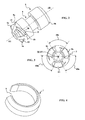
- FIGS. 9 to 15 illustrate a dental prosthetic assembly 27 according to a second embodiment according to the invention.
- the latch 5 is rotatably mounted and captive on the dental implant 2a or 2b.
- the dental implant 2a or 2b has an inner peripheral groove 22 of circular cross section, located in the inner part of the receiving cavity 150 formed in the dental implant 2a or 2b.
- the latch 5 comprises meanwhile, at its second end 5b, latching means 23 for penetrating the inner peripheral groove 22 of the receiving cavity 150.
- the latching means 23 comprise three fins 24a to 24c with free ends 240a to 240c with radial elastic displacement.
- the free ends 240a to 240c are also provided with ribs 241a to 241c intended to snap into the inner peripheral groove 22 and be retained by a shoulder 25 located above the inner peripheral groove 22.
- the polygonal cavity 17, for rotating the latch 5 extends longitudinally through the latch 5 over its length along its axial direction III-III and thus opens at the first end 5a of the latch 5.
- the dental prosthesis 3 is provided with the retaining cavity 15, as illustrated in FIGS. Figures 12 to 14 .
- the radial fins 6a to 6c and the protruding protuberances 16a to 16c are shaped in a manner similar to that explained with respect to the first embodiment of the invention illustrated in FIGS. Figures 1 to 8 .
- the connecting device 1 used in the second embodiment of the invention is similar to that explained in connection with the first embodiment of the invention, except that it is here the cavity of retainer 15 which is formed in the dental prosthesis 3 so as to be oriented in the patient's mouth in an axial direction VI-VI coaxial with the axial directions II or II-II dental implants 2a and 2b.
- the latch 5 is in turn arranged with its longitudinal direction III-III coinciding with the axial direction I-I or II-II dental implants 2a and 2b.
- the dentist When fixing the dental prosthesis 3 on the dental implants 2a and 2b, the dentist reports locks 5 in the upper part of the implants 2a and 2b by snapping. The dentist then places the dental prosthesis 3 on the dental arch of the patient. This pose is done perfectly if the radial vanes 6a to 6c are not in correspondence of protruding protuberances 16a to 16c. If this is not the case, the dentist slightly rotates the latches 5 using a rotational drive tool inserted in the access channels 18 to arrange the radial fins 6a to 6c in correspondence angular sectors 160a to 160c.
- the dentist then drives the latches 5 in rotation in their longitudinal direction III-III so as to cooperate the support facets 19 of the radial vanes 6a to 6c with the retaining facets 21 protruding protrusions 16a to 16c.
- the dentist introduces a rotational drive tool into the cavity 17 by passing through the access channel 18 and through the retaining cavity 15.
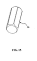
- the dentist inserts into the impression 17 the locking piece 26 illustrated on the figure 15 , which has an outer shape complementary to the inner shape of the footprint 17.
- the locking piece 26 has dimensions allowing insertion slightly in force in the footprint 17 of the latch 5. Once in place, as shown in FIG. figure 14 , the locking piece 26 prevents any centripetal radial bending of the elastic fins 24a to 24c, so that the ribs 241a to 241c remain well in position. position in the inner peripheral groove 22 located in the receiving cavity 150 formed in the dental implant 2a and 2b.
- trans-fixed type implant-borne multiple prosthesis that is to say fixed to several implants in the jaw of the patient
- the invention can also be used for a unitary prosthesis.
- implant-type trans-fixed type that is to say, attached to a single implant in the jaw of the patient.
- the connecting device according to the invention nevertheless has significant additional advantages in the case of a dental prosthetic assembly 27 comprising an implant-borne plural trans-fixed dental prosthesis 3 carried on a plurality of dental implants 2a and 2b, in particular during the placing phase of the dental prosthesis 3 on the dental arch of the patient.
- the implant-borne plural trans-fixed dental prosthesis 3 may include a connecting bar for mechanically interconnecting the dental implants on which the dental prosthesis 3 is fixed. In the embodiments illustrated in the figures, the dental prosthesis 3 has no link bar
Abstract
Ensemble prothétique dentaire (27) comprenant un implant dentaire (2a, 2b), une prothèse dentaire (3) trans-fixée et un dispositif de liaison (1) comportant : - un verrou (5) comportant au moins deux ailettes radiales (6a), monté rotatif et retenu en translation dans l'implant dentaire (2a, 2b) ou la prothèse dentaire (3), - une cavité de retenue (15) munie sur sa périphérie d'excroissances saillantes (16a) s'étendant radialement vers le centre de ladite cavité (15), ménagée dans la prothèse dentaire (3) ou l'implant dentaire (2a, 2b). Les ailettes radiales (6a) et les excroissances saillantes (16a) coopérent par rotation du verrou (5) pour retenir la prothèse dentaire (3) trans-fixée sur l'implant dentaire (2a, 2b), et pour permettre une pénétration du verrou (5) et de ses ailettes radiales (6a) dans ladite cavité (15) par translation axiale.Dental prosthetic assembly (27) comprising a dental implant (2a, 2b), a trans-fixed dental prosthesis (3) and a connecting device (1) comprising: - a latch (5) having at least two radial fins (6a) rotatably mounted and retained in translation in the dental implant (2a, 2b) or the dental prosthesis (3), - a retaining cavity (15) provided on its periphery with protruding protuberances (16a) extending radially towards the center of said cavity (15) formed in the dental prosthesis (3) or the dental implant (2a, 2b ). The radial fins (6a) and the protruding protuberances (16a) cooperate by rotation of the latch (5) to retain the dental prosthesis (3) trans-fixed on the dental implant (2a, 2b), and to allow a penetration of the latch (5) and its radial fins (6a) in said cavity (15) by axial translation.
Description
La présente invention concerne le domaine de l'implantologie dentaire, et notamment le traitement de l'édentement d'arcades dentaires avec un ensemble prothétique dentaire comportant une prothèse (éventuellement plurale) implanto-portée de type trans-fixée sur au moins un implant dentaire.The present invention relates to the field of dental implantology, and in particular the treatment of edentulous dental arches with a dental prosthetic assembly comprising an implant-supported (possibly plural) prosthesis of trans-fixed type on at least one dental implant. .
Une prothèse implanto-portée de type trans-fixée est destinée à reposer sur l'arcade dentaire du patient, en étant fixée à un ou plusieurs implants dentaires fixés dans l'os de la mâchoire du patient, pour former une ou plusieurs dents prothétiques. Afin de permettre le retrait éventuel ultérieur de la prothèse, par exemple pour réparation, la fixation de la prothèse aux implants est effectuée par l'intermédiaire de moyens de fixation (des vis dans l'état de la technique antérieur) traversant la prothèse, d'où l'expression de « prothèse trans-fixée ». La tête des vis est accessible depuis la face active de la prothèse (ou face de mastication).A trans-fixed type implant-supported prosthesis is intended to rest on the dental arch of the patient, being attached to one or more dental implants fixed in the jawbone of the patient, to form one or more prosthetic teeth. In order to allow the possible subsequent removal of the prosthesis, for example for repair, fixation of the prosthesis to the implants is carried out by means of fixing means (screws in the state of the prior art) passing through the prosthesis, where the expression "trans-fixed prosthesis". The head of the screws is accessible from the active side of the prosthesis (or chewing face).
Pour des raisons de résistance mécanique de la tenue de l'implant dans l'os de la mâchoire notamment, les implants sont orientés selon des directions axiales qui sont obliques entre elles et/ou obliques par rapport à la surface générale de l'arcade dentaire.For reasons of mechanical strength of the behavior of the implant in the bone of the jaw in particular, the implants are oriented in axial directions which are oblique to each other and / or oblique with respect to the general surface of the dental arch. .
Il est connu de fixer la prothèse implanto-portée aux implants par le biais de vis de trans-fixation. Du fait des orientations relatives obliques des implants entre eux, on a souvent recours à des piliers angulés. Un pilier angulé est une pièce intermédiaire, destinée à être rapportée sur l'implant selon une première direction axiale (correspondant à la direction longitudinale de l'implant), présentant une cavité filetée intérieurement et orientée selon une deuxième direction axiale faisant un angle avec la première direction axiale. La cavité filetée intérieurement reçoit la vis de trans-fixation selon la deuxième direction axiale.It is known to fix the implant-supported prosthesis to the implants by means of trans-fixation screws. Because of the oblique relative orientations of the implants between them, angular abutments are often used. An angled abutment is an intermediate piece, intended to be attached to the implant in a first axial direction (corresponding to the longitudinal direction of the implant), having an internally threaded cavity and oriented in a second axial direction at an angle to the first axial direction. The internally threaded cavity receives the trans-fixing screw in the second axial direction.
Pour amener et visser une vis de trans-fixation dans un pilier angulé, on prévoit dans la prothèse un canal d'accès pour un outil d'entraînement en rotation. Le canal d'accès est orienté selon une troisième direction axiale. L'orientation de ce canal d'accès doit être choisie avec soin en évitant que celui-ci ne débouche au sommet d'une dent prothétique en surface extérieure active de la prothèse, afin de ne pas affecter la résistance de la dent prothétique dans une zone devant supporter les contraintes de mastication. Pour gérer au mieux ces nécessités, le praticien chirurgien dentiste a à sa disposition de nombreux piliers intermédiaires d'encombrements et d'angles différents. Une orientation optimale entre les première, deuxième et troisième directions axiales n'est toutefois pas toujours possible malgré la disponibilité de nombreux piliers intermédiaires différents.To bring and screw a trans-fixation screw into an angled abutment, there is provided in the prosthesis an access channel for a rotary drive tool. The access channel is oriented in a third axial direction. The orientation of this access channel must be chosen carefully, so that it does not open at the top of a prosthetic tooth on the active outer surface of the prosthesis, so as not to affect the resistance of the prosthetic tooth in a tooth. area to withstand chewing constraints. To best manage these needs, the dentist practitioner has at his disposal many intermediate pillars of different dimensions and angles. Optimal orientation between the first, second and third axial directions is not always possible, however, despite the availability of many different intermediate pillars.
Il est donc souhaitable de proposer une solution de fixation amovible qui permette une orientation optimale du canal d'accès, en tenant compte de l'orientation de l'implant, et ce sans avoir recours à de trop nombreuses pièces à manipuler et à garder en stock pour le praticien.It is therefore desirable to provide a removable fixation solution which allows an optimal orientation of the access channel, taking into account the orientation of the implant, without having to use too many parts to handle and keep in mind. stock for the practitioner.
Pour atteindre ce but, la demanderesse a envisagé de rendre captives les vis de trans-fixation (par sertissage par exemple) de la prothèse, les vis de trans-fixation étant alors destinées à se visser directement dans les implants.To achieve this goal, the Applicant has considered captive screws for trans-fixation (for example crimping) of the prosthesis, the trans-fixing screws then being intended to be screwed directly into the implants.
Mais, pour qu'une prothèse trans-fixée soit installée correctement en bouche, et pour que le praticien puisse contrôler sa bonne adaptabilité avant fixation, plus particulièrement dans le cas d'une prothèse plurale implanto-portée, il faut commencer par une étape de posage de la prothèse sur l'arcade dentaire du patient. Dans la solution de sertissage de vis captives envisagée par la demanderesse, cela nécessite que les vis puissent être reçues en quasi-totalité dans la prothèse. Mais la longueur nécessaire des vis rend ceci le plus souvent impossible. Et quand bien même cela serait possible, la tête de vis est alors inatteignable pour être manoeuvrée par un outil d'entraînement en rotation amené via le canal d'accès, du fait de l'inclinaison entre les première et troisième directions.But, for a trans-fixed prosthesis to be correctly installed in the mouth, and so that the practitioner can control its good adaptability before fixation, more particularly in the case of an implant-borne multiple prosthesis, it is necessary to begin with a step of placing the prosthesis on the dental arch of the patient. In the solution for crimping captive screws envisaged by the applicant, this requires that the screws can be received almost entirely in the prosthesis. But the necessary length of the screws makes this most often impossible. And even if it were possible, the screw head is then unattainable to be operated by a rotary drive tool brought via the access channel, because of the inclination between the first and third directions.
Le document
Un problème proposé par la présente invention est de permettre une fixation optimale et amovible d'une prothèse implanto-portée de type trans-fixée, à l'aide de moyens de liaison aux implants qui présentent un moins grand nombre d'éléments constitutifs et qui autorisent un choix plus libre d'orientation du canal d'accès dans la prothèse.A problem proposed by the present invention is to allow optimal and removable attachment of a trans-fixed type implant-supported prosthesis, by means of implant connecting means which have a smaller number of constituent elements and which allow a more free choice of orientation of the access channel in the prosthesis.
Pour atteindre ces objets, ainsi que d'autres, l'invention propose un ensemble prothétique dentaire comprenant :
- un implant dentaire,
- une prothèse dentaire,
- un dispositif de liaison comportant une cavité de retenue ménagée dans l'un de l'implant dentaire ou de la prothèse dentaire, et munie sur sa périphérie d'excroissances saillantes s'étendant radialement vers le centre de la cavité de retenue ;
- la prothèse dentaire est de type trans-fixée,
- le dispositif de liaison comprend un verrou comportant au moins deux ailettes radiales, monté rotatif et retenu en translation dans l'autre de l'implant dentaire ou de la prothèse dentaire, les ailettes radiales et les excroissances saillantes étant conformées et dimensionnées de façon à permettre une pénétration du verrou et de ses ailettes radiales dans la cavité de retenue par un simple mouvement de translation axiale,
- les ailettes radiales et les excroissances saillantes sont conformées et dimensionnées de façon à coopérer par rotation du verrou pour retenir la prothèse dentaire trans-fixée sur l'implant dentaire.
- a dental implant,
- a dental prosthesis,
- a connecting device having a retaining cavity in one of the dental implant or the dental prosthesis, and provided on its periphery with projecting protuberances extending radially towards the center of the retaining cavity;
- the dental prosthesis is of trans-fixed type,
- the connecting device comprises a latch comprising at least two radial fins, rotatably mounted and retained in translation in the other of the dental implant or the dental prosthesis, the radial fins and the protruding projections being shaped and dimensioned so as to allow a penetration of the latch and its radial fins in the retaining cavity by a simple axial translation movement,
- the radial fins and protruding projections are shaped and dimensioned to cooperate by rotation of the latch to retain the dental prosthesis trans-fixed on the dental implant.
Le verrou monté dans la prothèse dentaire ou dans l'implant dentaire par l'intermédiaire d'une liaison pivot (ou pivot glissant) est directement orienté selon une direction destinée à être coaxiale avec la direction axiale de l'implant, ce qui évite d'avoir recours à des piliers angulés.The latch mounted in the dental prosthesis or in the dental implant via a pivot connection (or sliding pivot) is directly oriented in a direction intended to be coaxial with the axial direction of the implant, thereby avoiding use angled abutments.
Le dispositif de liaison selon l'invention peut présenter un encombrement axial très limité, dès lors que des ailettes peuvent occuper une faible dimension dans la direction axiale du verrou. De plus, son engagement par simple mouvement de translation axiale et la conformation des ailettes radiales et excroissances saillantes facilitent la phase de posage de la prothèse sur l'arcade dentaire. Pour être retenu dans la cavité de retenue, le verrou n'a besoin d'être entraîné en rotation que selon moins d'un tour complet. La manoeuvre du verrou est ainsi rapide et facile. La course axiale nécessaire pour manoeuvrer le verrou et l'amener à être retenu dans la cavité de retenue est ainsi très réduite.The connecting device according to the invention may have a very limited axial size, since fins may occupy a small dimension in the axial direction of the latch. In addition, its commitment by simple axial translation movement and the conformation of radial fins and protruding projections facilitate the phase of setting the prosthesis on the dental arch. To be retained in the retaining cavity, the latch only needs to be rotated within less than one complete revolution. The operation of the lock is thus quick and easy. The axial stroke necessary to manipulate the lock and cause it to be retained in the retaining cavity is thus very small.
De préférence, on peut prévoir que :
- les ailettes radiales du verrou sont séparées entre elles par des secteurs angulaires dimensionnés de façon à laisser passer une excroissance saillante par un simple mouvement de translation axiale,
- les excroissances saillantes de la cavité de retenue sont séparées entre elles par des secteurs angulaires dimensionnés de façon à laisser passer une ailette radiale lors dudit simple mouvement de translation axiale.
- the radial vanes of the latch are separated from each other by angular sectors sized so as to allow a protruding protrusion to pass through a simple axial translation movement,
- the protruding protuberances of the retaining cavity are separated from each other by angular sectors sized so as to let a radial fin pass during said simple axial translation movement.
Avantageusement, les ailettes radiales du verrou peuvent être portées par un premier tronçon d'extrémité sensiblement conique ou tronconique. Le premier tronçon d'extrémité sensiblement conique ou tronconique permet un guidage progressif du verrou pour le centrer par rapport à la cavité de retenue. L'expression « tronçon d'extrémité sensiblement tronconique » est entendue comme désignant toute forme géométrique s'affinant progressivement, pouvant être une extrémité arrondie par exemple.Advantageously, the radial vanes of the lock can be carried by a first substantially conical or frustoconical end portion. The first substantially conical or frustoconical end portion allows progressive guiding of the latch to center it with respect to the retaining cavity. The expression "substantially frustoconical end portion" is understood to denote any gradually refined geometric shape, which may be a rounded end for example.
De préférence, le verrou peut comporter une empreinte permettant son entraînement en rotation à l'aide d'un outil. Cette empreinte peut être située à une extrémité du verrou opposée à l'extrémité portant les ailettes radiales.Preferably, the lock may include a fingerprint for driving it in rotation using a tool. This impression may be located at one end of the lock opposite the end bearing the radial fins.
Avantageusement, les ailettes radiales peuvent comporter une facette d'appui à rampe progressive destinée à venir porter contre une excroissance saillante de la cavité de retenue, et/ou les excroissances saillantes peuvent comporter une facette de retenue à rampe progressive destinée à venir porter contre une ailette radiale du verrou.Advantageously, the radial fins may comprise a progressive ramp support facet intended to bear against a projecting protuberance of the retaining cavity, and / or the protruding protuberances may comprise a progressive ramp retaining facet intended to bear against a radial blade of the lock.
La ou les rampes des facettes d'appui et/ou de retenue permettent un guidage radial et un entraînement en translation de la prothèse par rapport à l'implant lors de la manoeuvre en rotation du verrou, et assurent un excellent plaquage de la prothèse sur l'implant.The ramp or ramps of the support and / or retaining facets allow radial guidance and drive in translation of the prosthesis with respect to the implant during the rotation of the lock, and ensure excellent prosthesis placement on the implant.
Dans un premier mode de réalisation selon l'invention, le verrou peut être monté rotatif et retenu en translation dans la prothèse dentaire par l'intermédiaire d'une bague de retenue compressible, de préférence au moyen d'une fente, venant simultanément en prise dans une gorge périphérique extérieure ménagée sur le verrou et dans une gorge périphérique intérieure ménagée dans la prothèse dentaire.In a first embodiment according to the invention, the latch can be rotatably mounted and retained in translation in the dental prosthesis by means of a compressible retaining ring, preferably by means of a slot, simultaneously engaging in an outer peripheral groove formed on the latch and in an inner peripheral groove in the dental prosthesis.
Le verrou est ainsi disposé en liaison pivot (ou pivot glissant) dans la prothèse et est maintenu captif dans la prothèse de façon simple et efficace.The lock is thus arranged in pivot connection (or sliding pivot) in the prosthesis and is held captive in the prosthesis in a simple and effective manner.
Pour assurer la liaison entre la prothèse et l'implant, le praticien introduit un outil d'entraînement en rotation dans le canal d'accès ménagé dans la prothèse jusqu'à engager l'outil sur le verrou pour le pousser dans la cavité de retenue de l'implant puis pour l'entraîner en rotation.To ensure the connection between the prosthesis and the implant, the practitioner introduces a rotational drive tool in the access channel in the prosthesis until the tool is engaged on the lock to push it into the retaining cavity of the implant then to rotate it.
Pour permettre toutefois un démontage du verrou si celui-ci venait à être accidentellement détérioré, la prothèse dentaire peut avantageusement comporter une pluralité de canaux axiaux débouchants s'étendant jusqu'à la gorge périphérique intérieure ménagée dans la prothèse dentaire.To allow, however, disassembly of the lock if it had to be accidentally damaged, the dental prosthesis may advantageously comprise a plurality of axial ducts extending to the inner peripheral groove in the dental prosthesis.
On peut ainsi introduire un outil de retrait de verrou, comportant une pluralité de tiges adaptées pour pénétrer dans les canaux axiaux jusqu'à venir porter en appui contre la bague de retenue compressible pour la presser radialement de façon centripète afin d'en diminuer les dimensions radiales, puis extraire la bague de retenue hors de la prothèse dentaire et ainsi libérer le verrou.It is thus possible to introduce a lock removal tool comprising a plurality of rods adapted to penetrate into the axial channels until they come bear against the compressible retaining ring to press it radially centripetally in order to reduce the radial dimensions, then extract the retaining ring out of the dental prosthesis and release the lock.
De préférence, la gorge périphérique intérieure ménagée dans la prothèse dentaire, et/ou la gorge périphérique extérieure ménagée sur le verrou, présentent une hauteur légèrement supérieure à celle de la bague de retenue, permettant un jeu axial en translation entre la prothèse dentaire et le verrou.Preferably, the inner peripheral groove formed in the dental prosthesis, and / or the outer peripheral groove formed on the latch, have a height slightly greater than that of the retaining ring, allowing axial play in translation between the dental prosthesis and the lock.
Les jeux axiaux en translation induits par la différence de hauteurs entre d'une part la bague de retenue et d'autre part la gorge périphérique intérieure ménagée dans la prothèse et/ou la gorge périphérique extérieure ménagée sur le verrou, permettent un montage aisé de la bague, donc du verrou, dans la prothèse. Cela permet également au verrou de reculer un peu dans la prothèse pour y être partiellement ou totalement reçu dans le cas où les ailettes radiales du verrou ne sont pas strictement alignées avec les espaces entre les excroissances saillantes de la cavité de retenue lors du posage de la prothèse sur l'arcade dentaire. Autrement dit, le verrou est disposé en liaison pivot glissant dans la prothèse, avec une course de glissement déterminée par le jeu axial en translation entre la prothèse dentaire et le verrou.The axial clearances in translation induced by the difference in height between, on the one hand, the retaining ring and, on the other hand, the inner peripheral groove formed in the prosthesis and / or the outer peripheral groove formed on the latch, allow easy assembly of the ring, therefore the lock, in the prosthesis. This also allows the latch to move back a little in the prosthesis to be partially or totally received in the case where the radial vanes of the latch are not strictly aligned with the spaces between the projecting protuberances of the retaining cavity during the installation of the prosthesis on the dental arch. In other words, the lock is arranged in sliding pivot connection in the prosthesis, with a sliding stroke determined by the axial clearance in translation between the dental prosthesis and the lock.
Dans un deuxième mode de réalisation selon l'invention, le verrou peut être monté rotatif et retenu en translation dans l'implant dentaire par l'intermédiaire :
- d'une gorge périphérique intérieure située dans une cavité de réception ménagée dans l'implant dentaire,
- d'une deuxième extrémité de verrou comportant des moyens d'encliquetage destinés à pénétrer dans la gorge périphérique intérieure de la cavité de réception.
- an inner peripheral groove located in a receiving cavity formed in the dental implant,
- a second latch end having latching means for penetrating the inner peripheral groove of the receiving cavity.
Pour assurer la liaison entre la prothèse et l'implant, le praticien engage la prothèse sur l'implant et le verrou pour que le premier tronçon d'extrémité du verrou pénètre dans la cavité de retenue de la prothèse, puis il introduit un outil d'entraînement en rotation dans le canal d'accès ménagé dans la prothèse, et traverse la prothèse en passant à travers la cavité de retenue ménagée dans la prothèse pour parvenir jusqu'au verrou, disposé sur l'implant, et l'entraîner en rotation.To ensure the connection between the prosthesis and the implant, the practitioner engages the prosthesis on the implant and the lock so that the first end portion of the lock enters the retaining cavity of the prosthesis, then introduces a prosthesis tool. rotational drive in the access channel formed in the prosthesis, and through the prosthesis passing through the retaining cavity in the prosthesis to reach the lock, disposed on the implant, and rotate it .
Tous les modes de réalisation permettent de limiter le stock de composants chez les praticiens, simplifient la procédure chirurgicale, limitent l'encombrement des éléments constitutifs de la liaison entre la prothèse et le ou les implants, et rendent plus flexible le choix de l'orientation des canaux d'accès prévus dans la prothèse.All embodiments make it possible to limit the stock of components among practitioners, simplify the surgical procedure, limit the bulk of the constituent elements of the connection between the prosthesis and the implant (s), and make the choice of orientation more flexible. access channels provided in the prosthesis.
Le deuxième mode de réalisation présente en outre l'avantage que la majeure partie de l'encombrement du dispositif de liaison se trouve du côté de l'implant, l'empreinte située sur la prothèse présentant un encombrement extrêmement réduit. Le prothésiste est donc encore moins contraint, lors de la fabrication de la prothèse, pour orienter les canaux d'accès.The second embodiment further has the advantage that the bulk of the bulk of the connecting device is on the side of the implant, the footprint on the prosthesis having an extremely small footprint. The prosthetist is therefore even less constrained, during the manufacture of the prosthesis, to guide the access channels.
D'autres objets, caractéristiques et avantages de la présente invention ressortiront de la description suivante de modes de réalisation particuliers, faite en relation avec les figures jointes, parmi lesquelles :
- la
figure 1 est une vue en perspective d'une partie d'une prothèse dentaire trans-fixée sur des implants dentaires par des dispositifs de liaison, représentative d'un premier mode de réalisation d'un ensemble prothétique dentaire selon l'invention ; - la
figure 2 est une vue en perspective d'un verrou utilisé dans un dispositif de liaison du premier mode de réalisation d'ensemble prothétique dentaire selon l'invention ; - la
figure 3 est une vue de dessous du verrou de lafigure 2 ; - la
figure 4 est une vue en perspective d'une bague de retenue compressible destinée à être utilisée avec un verrou tel que représenté sur lesfigures 2 ;et 3 - la
figure 5 est une vue en coupe de la prothèse dentaire illustrée sur lafigure 1 ; - la
figure 6 est une vue de dessus d'un implant sur lequel est destinée à être rapportée la prothèse dentaire illustrée sur lafigure 5 ; - la
figure 7 est une vue en perspective de l'implant de lafigure 6 ; - la
figure 8 est une vue en coupe illustrant la coopération de la prothèse dentaire illustrée sur lafigure 5 avec l'implant illustré sur lesfigures 6 ;et 7 - la
figure 9 est une vue en perspective d'un verrou utilisé dans un ensemble prothétique dentaire selon un deuxième mode de réalisation de l'invention ; - la
figure 10 est une vue en perspective d'un implant destiné à recevoir, à son extrémité supérieure, le verrou illustré sur lafigure 9 ; - la
figure 11 est une vue en coupe de l'implant de lafigure 10 muni d'un verrou tel qu'illustré sur lafigure 9 ; - la
figure 12 est une vue en coupe d'une prothèse dentaire destinée à être retenue sur l'implant de lafigure 11 ; - la
figure 13 est une vue en perspective d'une cavité de retenue prévue dans la prothèse dentaire illustrée sur lafigure 12 ; - la
figure 14 est une vue en coupe illustrant la coopération de la prothèse dentaire illustrée sur lafigure 12 avec l'implant illustré sur lafigure 11 ; et - la
figure 15 est une vue en perspective d'une pièce de verrouillage.
- the
figure 1 is a perspective view of a portion of a dental prosthesis trans-fixed on dental implants by connecting devices, representative of a first embodiment of a dental prosthetic assembly according to the invention; - the
figure 2 is a perspective view of a latch used in a connecting device of the first embodiment of dental prosthetic assembly according to the invention; - the
figure 3 is a bottom view of the lock of thefigure 2 ; - the
figure 4 is a perspective view of a compressible retaining ring for use with a latch as shown in FIGS.Figures 2 and 3 ; - the
figure 5 is a sectional view of the dental prosthesis shown on thefigure 1 ; - the
figure 6 is a top view of an implant on which is intended to be reported the dental prosthesis illustrated on thefigure 5 ; - the
figure 7 is a perspective view of the implant of thefigure 6 ; - the
figure 8 is a sectional view illustrating the cooperation of the dental prosthesis illustrated on thefigure 5 with the implant shown on theFigures 6 and 7 ; - the
figure 9 is a perspective view of a latch used in a dental prosthetic assembly according to a second embodiment of the invention; - the
figure 10 is a perspective view of an implant intended to receive, at its upper end, the lock illustrated on thefigure 9 ; - the
figure 11 is a sectional view of the implant of thefigure 10 equipped with a lock as shown on thefigure 9 ; - the
figure 12 is a sectional view of a dental prosthesis intended to be retained on the implant of thefigure 11 ; - the
figure 13 is a perspective view of a retaining cavity provided in the dental prosthesis illustrated on thefigure 12 ; - the
figure 14 is a sectional view illustrating the cooperation of the dental prosthesis illustrated on thefigure 12 with the implant shown on thefigure 11 ; and - the
figure 15 is a perspective view of a locking piece.
Les
Comme illustré sur la
L'implant dentaire plus spécifiquement désigné par la référence 2a présente une direction d'allongement II-II déterminant sa direction axiale de vissage dans la mâchoire du patient. L'implant dentaire 2a est vissé sur la partie antérieure de la mâchoire du patient.The dental implant more specifically designated by
De façon similaire, l'implant dentaire plus spécifiquement désigné par la référence 2b présente une direction d'allongement I-I définissant sa direction de vissage dans la partie postérieure de la mâchoire du patient.Similarly, the dental implant more specifically designated by
On observe, dans l'exemple illustré sur la
Pour fixer la prothèse dentaire 3 sur les implants dentaires 2a et 2b, on a recours à des dispositifs de liaison 1 comportant chacun un verrou 5 plus particulièrement illustré sur les
Chaque verrou 5 est monté dans la prothèse dentaire 3 au moyen d'une bague de retenue 7 compressible telle qu'illustrée sur la
Comme illustré sur la
Le logement de réception 10 présente, dans sa partie inférieure, un épaulement 12 annulaire de sorte que le logement de réception 10 présente en partie inférieure un orifice inférieur 14 de section transversale plus petite que le diamètre extérieur de la bague de retenue 7. Grâce à son caractère compressible, la bague de retenue 7 peut diminuer de diamètre extérieur pour pénétrer dans l'orifice inférieur 14 et passer l'épaulement 12 en enserrant de plus près le fond de la gorge périphérique extérieure 9. Une fois que le verrou 5 muni de sa bague de retenue 7 a été inséré axialement dans le logement de réception 10, la bague de retenue 7 s'épanouit radialement et vient simultanément en prise dans la gorge périphérique extérieure 9 et dans la gorge périphérique intérieure 11. Le verrou 5 est ainsi retenu captif dans la prothèse dentaire 3.The receiving
Dans le cas où le verrou 5 est endommagé, il peut être nécessaire de le retirer en dehors du logement de réception 10 sans endommager la prothèse dentaire 3.In the case where the
Pour ce faire, il est prévu des canaux axiaux 13, illustrés en traits discontinus sur la
Le verrou 5 est destiné à coopérer directement avec un implant dentaire 2a ou 2b tel qu'illustré sur les
Les ailettes radiales 6a à 6c et les excroissances saillantes 16a à 16c sont conformées et dimensionnées de façon à coopérer par rotation du verrou 5 pour retenir la prothèse dentaire 3 trans-fixée sur l'implant dentaire 2. De plus, les ailettes radiales 6a à 6c et les excroissances saillantes 16a à 16c sont conformées dimensionnellement de façon à permettre une pénétration du verrou 5 et de ses ailettes radiales 6a à 6c dans la cavité de retenue 15 par un simple mouvement de translation axiale illustré par la flèche 170 sur la
Pour ce faire, les ailettes radiales 6a à 6c du verrou 5 sont séparées entre elles par des secteurs angulaires 60a à 60c dimensionnés de façon à laisser passer une excroissance saillante 16a, 16b ou 16c lors du mouvement de translation axiale 170. De plus, les excroissances saillantes 16a à 16c de la cavité de retenue 15 sont séparées entre elles par des secteurs angulaires 160a à 160c dimensionnés de façon à laisser passer une ailette radiale 6a, 6b ou 6c lors du simple mouvement de translation axiale 170. Dans l'exemple illustré sur les
On voit plus particulièrement sur la
On voit plus particulièrement sur la
L'empreinte 17 peut notamment être conçue selon les enseignements du document
En alternative ou en complément, l'outil en rotation peut être spécifiquement adapté pour entraîner en rotation le verrou 5 en accédant à l'empreinte 17 via le canal d'accès 18 qui s'étend selon une direction axiale IV-IV ou V-V oblique par rapport à la direction axiale III-III (
On voit plus particulièrement sur la
En alternative ou en complément, les excroissances saillantes 16a à 16c peuvent comporter une facette de retenue 21 à rampe progressive destinée à venir porter contre une ailette radiale 6a à 6c du verrou 5.Alternatively or additionally, protruding
Pour réaliser la prothèse dentaire 3 destinée à être fixée sur les implants dentaires 2a et 2b préalablement implantés dans la mâchoire du patient, le prothésiste utilise une empreinte prise par le dentiste et permettant de repérer les directions I-I et II-II selon lesquelles sont orientés les implants 2a et 2b. De la sorte, le prothésiste peut prévoir d'orienter les verrous 5 par rapport à la prothèse dentaire 3 de façon à faire coïncider les directions axiales d'allongement III-III des verrous 5 avec les directions axiales I-I et II-II, tout en plaçant les canaux d'accès 18 orientés selon les directions respectives IV-IV et V-V de façon à procurer un accès aux verrous 5 et à autoriser un entraînement en rotation des verrous 5 selon les directions axiales III-III au moyen d'un outil d'entraînement en rotation permettant un effet de rotule. L'effet de rotule permet une grande liberté de choix des angles entre les directions axiales I-I et V-V d'une part et II-II et IV-IV d'autre part. Le prothésiste peut ainsi placer les canaux d'accès 18 de façon qu'ils ne débouchent pas sur une zone de surface active de dent destinée à supporter des efforts de mastication importants.To produce the
Une fois la prothèse dentaire 3 fabriquée par le prothésiste, celle-ci est envoyée chez le dentiste pour être fixée en bouche du patient sur les implants dentaires 2a et 2b.Once the
Pour ce faire, le dentiste commence par effectuer un posage de la prothèse dentaire 3 sur l'arcade dentaire du patient afin de vérifier la bonne adéquation de la prothèse dentaire 3 avec l'espace en bouche.To do this, the dentist begins by placing the
Lors de cette phase de posage, les verrous 5 se trouvent avec leur direction longitudinale III-III coaxiale aux directions axiales I-I et II-II.During this setting phase, the
Si les ailettes radiales 6a à 6c se trouvent en correspondance des secteurs angulaires 160a à 160c, le verrou 5 et ses ailettes radiales 6a à 6c pénètrent dans la cavité de retenue 15 par un simple mouvement de translation axiale lors du posage de la prothèse dentaire 3 sur l'arcade dentaire du patient. La prothèse dentaire 3 peut ainsi venir de façon satisfaisante en appui sur toute la longueur de l'arcade dentaire du patient.If the
Une fois le posage réalisé et les vérifications effectuées, le dentiste entraîne en rotation les verrous 5 par l'intermédiaire d'un outil d'entraînement en rotation qu'il insère dans les canaux d'accès 18 selon les directions axiales IV-IV et V-V. L'outil d'entraînement en rotation est conformé de façon à permettre l'entraînement en rotation du verrou 5 avec un effet de rotule tel que décrit par exemple dans le document
Lors de l'entraînement en rotation des verrous 5, les ailettes radiales 6a à 6c viennent selon leurs facettes d'appui 19 en appui contre les facettes de retenue 21 des excroissances saillantes 16a à 16c, et les rampes progressives 20 des facettes d'appui 19 achèvent de plaquer la prothèse dentaire 3 sur les implants dentaires 2a et 2b. On se retrouve alors dans la position illustrée sur la
Il est toutefois possible que, lors du posage de la prothèse dentaire 3 sur l'arcade dentaire du patient, les ailettes radiales 6a à 6c se trouvent au moins partiellement en correspondance des excroissances saillantes 16a à 16c. Pour éviter dans ce cas que les verrous 5 empêchent un bon plaquage de la prothèse dentaire 3 sur l'arcade dentaire du patient, on prévoit que la gorge périphérique intérieure 11 présente une hauteur H1 légèrement supérieure à la hauteur H2 de la bague de retenue 7. Cette différence entre les hauteurs H1 et H2 induit un jeu axial j en translation entre la prothèse dentaire 3 et les verrous 5. En pratique, le jeu axial j et la longueur L du logement de réception 10 sont dimensionnés de façon à permettre un déplacement du verrou 5 dans la prothèse dentaire 3 afin que celui-ci n'empêche pas un posage satisfaisant de la prothèse dentaire 3 sur l'arcade dentaire du patient. Le jeu j et la longueur L sont également dimensionnés de façon à ce que l'outil d'entraînement en rotation puisse toujours entraîner efficacement le verrou 5 en rotation selon la direction axiale III-III en étant inséré dans le canal d'accès 18 orienté selon la direction axiale IV-IV, malgré le recul du verrou 5.It is possible, however, that when the
Les
Dans ce deuxième mode de réalisation, le verrou 5 est monté rotatif et captif sur l'implant dentaire 2a ou 2b. Pour ce faire, l'implant dentaire 2a ou 2b comporte une gorge périphérique intérieure 22 à section transversale circulaire, située en partie intérieure de la cavité de réception 150 ménagée dans l'implant dentaire 2a ou 2b. Plus particulièrement visible sur les
L'empreinte 17 polygonale, permettant d'entraîner en rotation le verrou 5, traverse longitudinalement le verrou 5 sur sa longueur selon sa direction axiale III-III et débouche ainsi à la première extrémité 5a du verrou 5.The
De son côté, la prothèse dentaire 3 est munie de la cavité de retenue 15, comme illustré sur les
Les ailettes radiales 6a à 6c et les excroissances saillantes 16a à 16c sont conformées de façon similaire à ce qui a été expliqué en lien avec le premier mode de réalisation de l'invention illustré sur les
Le dispositif de liaison 1 utilisé dans le deuxième mode de réalisation de l'invention est similaire à ce qui a été expliqué en lien avec le premier mode de réalisation de l'invention, si ce n'est que c'est ici la cavité de retenue 15 qui est ménagée dans la prothèse dentaire 3 de façon à être orientée en bouche du patient selon une direction axiale VI-VI coaxiale avec les directions axiales I-I ou II-II des implants dentaires 2a et 2b. Le verrou 5 est quant à lui disposé avec sa direction longitudinale III-III coïncidant avec la direction axiale I-I ou II-II des implants dentaires 2a et 2b.The connecting
Lors de la fixation de la prothèse dentaire 3 sur les implants dentaires 2a et 2b, le dentiste rapporte des verrous 5 en partie supérieure des implants 2a et 2b par encliquetage. Le dentiste pose alors la prothèse dentaire 3 sur l'arcade dentaire du patient. Ce posage se fait de façon parfaite si les ailettes radiales 6a à 6c ne sont pas en correspondance des excroissances saillantes 16a à 16c. Si tel n'est pas le cas, le dentiste entraîne légèrement en rotation les verrous 5 à l'aide d'un outil d'entraînement en rotation inséré dans les canaux d'accès 18 afin de disposer les ailettes radiales 6a à 6c en correspondance des secteurs angulaires 160a à 160c.When fixing the
Si le posage s'avère satisfaisant, le dentiste entraîne alors les verrous 5 en rotation selon leur direction longitudinale III-III de façon à faire coopérer les facettes d'appui 19 des ailettes radiales 6a à 6c avec les facettes de retenue 21 des excroissances saillantes 16a à 16c. Pour ce faire, le dentiste introduit un outil d'entraînement en rotation dans l'empreinte 17 en passant dans le canal d'accès 18 et à travers la cavité de retenue 15.If the pose proves satisfactory, the dentist then drives the
Afin de garantir que les verrous 5 restent bien à demeure sur les implants dentaires 2a et 2b, le dentiste insère dans l'empreinte 17 la pièce de verrouillage 26 illustrée sur la
On se trouve alors dans la position illustrée sur la
Bien que la description précédente ait été effectuée en lien avec une prothèse plurale implanto-portée de type trans-fixée, c'est-à-dire fixée à plusieurs implants dans la mâchoire du patient, l'invention est également utilisable pour une prothèse unitaire implanto-portée de type trans-fixée, c'est-à-dire fixée à un seul implant dans la mâchoire du patient.Although the foregoing description has been made in connection with a trans-fixed type implant-borne multiple prosthesis, that is to say fixed to several implants in the jaw of the patient, the invention can also be used for a unitary prosthesis. implant-type trans-fixed type, that is to say, attached to a single implant in the jaw of the patient.
Le dispositif de liaison selon l'invention présente néanmoins des avantages supplémentaires importants dans le cas d'un ensemble prothétique dentaire 27 comprenant une prothèse dentaire 3 trans-fixée plurale implanto-portée sur une pluralité d'implants dentaires 2a et 2b, notamment lors de la phase de posage de la prothèse dentaire 3 sur l'arcade dentaire du patient.The connecting device according to the invention nevertheless has significant additional advantages in the case of a dental
La prothèse dentaire 3 trans-fixée plurale implanto-portée peut inclure une barre de liaison destinée à relier mécaniquement entre eux les implants dentaires sur lesquels vient se fixer la prothèse dentaire 3. Dans les modes de réalisation illustrés sur les figures, la prothèse dentaire 3 est dépourvue de barre de liaison.The implant-borne plural trans-fixed
La présente invention n'est pas limitée aux modes de réalisation qui ont été explicitement décrits, mais elle en inclut les diverses variantes et généralisations contenues dans le domaine des revendications ci-après.The present invention is not limited to the embodiments which have been explicitly described, but it includes the various variants and generalizations thereof within the scope of the claims below.
Claims (11)
Applications Claiming Priority (1)
| Application Number | Priority Date | Filing Date | Title |
|---|---|---|---|
| FR1360411A FR3012319B1 (en) | 2013-10-25 | 2013-10-25 | CONNECTION DEVICE BETWEEN A DENTAL IMPLANT AND A TRANS-FIXED DENTAL PROSTHESIS |
Publications (2)
| Publication Number | Publication Date |
|---|---|
| EP2865353A1 true EP2865353A1 (en) | 2015-04-29 |
| EP2865353B1 EP2865353B1 (en) | 2018-06-27 |
Family
ID=49713366
Family Applications (1)
| Application Number | Title | Priority Date | Filing Date |
|---|---|---|---|
| EP14189176.2A Active EP2865353B1 (en) | 2013-10-25 | 2014-10-16 | Dental prosthetic assembly comprising a dental implant and a transfixed dental prosthesis |
Country Status (7)
| Country | Link |
|---|---|
| US (1) | US9579169B2 (en) |
| EP (1) | EP2865353B1 (en) |
| JP (1) | JP5925276B2 (en) |
| CN (1) | CN104546163B (en) |
| BR (1) | BR102014026897A2 (en) |
| ES (1) | ES2681596T3 (en) |
| FR (1) | FR3012319B1 (en) |
Cited By (1)
| Publication number | Priority date | Publication date | Assignee | Title |
|---|---|---|---|---|
| EP3294190B1 (en) * | 2015-05-12 | 2020-06-24 | Thomas Jehle | Friction element |
Families Citing this family (12)
| Publication number | Priority date | Publication date | Assignee | Title |
|---|---|---|---|---|
| US8747112B2 (en) | 2011-12-30 | 2014-06-10 | Nobel Biocare Services Ag | Abutment position locator |
| FR3033692A1 (en) * | 2015-03-17 | 2016-09-23 | Anthogyr Sa | TRANSFIXED PLURAL DENTAL PROSTHESIS |
| FR3035786A1 (en) * | 2015-05-06 | 2016-11-11 | Anthogyr Sa | CONNECTION DEVICE BETWEEN A DENTAL PROSTHESIS AND A MASTER-MODEL |
| JP6959146B2 (en) * | 2015-06-08 | 2021-11-02 | バイオメット 3アイ,リミティド ライアビリティ カンパニー | Screwless dental implant connection |
| TW201808233A (en) * | 2016-06-02 | 2018-03-16 | 康洛格生物科技公司 | Retainer, combination of a packaging and a retainer, adapter and a retainer with a support structure for a surgical device |
| WO2019109320A1 (en) * | 2017-12-08 | 2019-06-13 | 辰庚事业股份有限公司 | Artificial tooth with vertical bone beam structure |
| EP3632367A1 (en) * | 2018-10-03 | 2020-04-08 | Nobel Biocare Services AG | Dental component with a retention interface |
| KR101966407B1 (en) * | 2018-11-21 | 2019-04-05 | 주식회사 하이니스 | Abutment assembly |
| IL266021A (en) * | 2019-04-14 | 2020-10-28 | Mikambeh Ltd | Dental abutment and abutting system |
| KR102454967B1 (en) * | 2022-01-05 | 2022-10-13 | 김경록 | Dental Implant system |
| KR102483796B1 (en) * | 2022-01-26 | 2023-01-03 | 주식회사 씨앤지치과기공소 | Abutment for dental Implant |
| KR102636643B1 (en) * | 2023-04-27 | 2024-02-13 | 신동현 | Upper structure of Dental implant |
Citations (4)
| Publication number | Priority date | Publication date | Assignee | Title |
|---|---|---|---|---|
| EP0867154A1 (en) * | 1997-03-27 | 1998-09-30 | Cendres Et Metaux S.A. | Device for releasably mounting dental prosthesis |
| EP1992304A1 (en) | 2007-05-12 | 2008-11-19 | Gerd Axel Dr. Walther | Dental implant, in particular made of a ceramic material |
| EP2607722A1 (en) | 2011-12-22 | 2013-06-26 | Straumann Holding AG | Connecting screw for a dental implant |
| KR101311250B1 (en) * | 2012-04-06 | 2013-09-27 | 김만용 | Attachment for denture |
Family Cites Families (11)
| Publication number | Priority date | Publication date | Assignee | Title |
|---|---|---|---|---|
| JPS5035952U (en) * | 1973-07-31 | 1975-04-16 | ||
| JPS58191413U (en) * | 1982-06-15 | 1983-12-20 | 日本工機株式会社 | bolt nut |
| IT1311004B1 (en) * | 1999-03-16 | 2002-02-27 | Antonio Gallicchio | IMPLANT FOR ARTIFICIAL TEETH. |
| AU5615299A (en) * | 1999-09-22 | 2001-04-24 | Lipat Consulting Ag | Screw-type intraossal dental implant |
| EP2046238B1 (en) * | 2006-08-01 | 2015-06-17 | BONDAR, Vitali | Dental Implant System |
| US7704076B2 (en) * | 2006-12-20 | 2010-04-27 | Zest Ip Holdings Llc | Dental attachment assembly and method |
| ES2557555T3 (en) * | 2007-03-19 | 2016-01-27 | Straumann Holding Ag | Combination of a pillar and a two-part screw |
| EP2223667B1 (en) * | 2009-02-26 | 2013-11-20 | Nobel Biocare Services AG | A dental implant kit |
| CH704382A1 (en) * | 2011-01-25 | 2012-07-31 | Dentalpoint Ag | Dentures system. |
| WO2012132057A1 (en) * | 2011-03-28 | 2012-10-04 | 株式会社T・U・M | Denture system, and method for creating and method for repairing denture |
| EP2653131B1 (en) * | 2012-04-19 | 2018-02-28 | Dentsply IH AB | A dental implant set |
-
2013
- 2013-10-25 FR FR1360411A patent/FR3012319B1/en not_active Expired - Fee Related
-
2014
- 2014-10-15 US US14/515,049 patent/US9579169B2/en active Active
- 2014-10-16 ES ES14189176.2T patent/ES2681596T3/en active Active
- 2014-10-16 EP EP14189176.2A patent/EP2865353B1/en active Active
- 2014-10-23 JP JP2014215961A patent/JP5925276B2/en active Active
- 2014-10-27 BR BR102014026897A patent/BR102014026897A2/en active Search and Examination
- 2014-10-27 CN CN201410584697.1A patent/CN104546163B/en active Active
Patent Citations (4)
| Publication number | Priority date | Publication date | Assignee | Title |
|---|---|---|---|---|
| EP0867154A1 (en) * | 1997-03-27 | 1998-09-30 | Cendres Et Metaux S.A. | Device for releasably mounting dental prosthesis |
| EP1992304A1 (en) | 2007-05-12 | 2008-11-19 | Gerd Axel Dr. Walther | Dental implant, in particular made of a ceramic material |
| EP2607722A1 (en) | 2011-12-22 | 2013-06-26 | Straumann Holding AG | Connecting screw for a dental implant |
| KR101311250B1 (en) * | 2012-04-06 | 2013-09-27 | 김만용 | Attachment for denture |
Cited By (1)
| Publication number | Priority date | Publication date | Assignee | Title |
|---|---|---|---|---|
| EP3294190B1 (en) * | 2015-05-12 | 2020-06-24 | Thomas Jehle | Friction element |
Also Published As
| Publication number | Publication date |
|---|---|
| FR3012319A1 (en) | 2015-05-01 |
| FR3012319B1 (en) | 2016-09-02 |
| US9579169B2 (en) | 2017-02-28 |
| BR102014026897A2 (en) | 2016-01-05 |
| JP2015083129A (en) | 2015-04-30 |
| CN104546163B (en) | 2017-06-13 |
| US20150118651A1 (en) | 2015-04-30 |
| CN104546163A (en) | 2015-04-29 |
| JP5925276B2 (en) | 2016-05-25 |
| EP2865353B1 (en) | 2018-06-27 |
| ES2681596T3 (en) | 2018-09-14 |
Similar Documents
| Publication | Publication Date | Title |
|---|---|---|
| EP2865353B1 (en) | Dental prosthetic assembly comprising a dental implant and a transfixed dental prosthesis | |
| EP3573568B1 (en) | Set of components for dental prosthetic restoration | |
| EP1034750B1 (en) | Dental implant having anti-rotation means for the upperstructures | |
| CH663349A5 (en) | DENTAL FIXING STRUCTURE. | |
| EP3202365A1 (en) | Dental component for the individual prosthetic reconstruction of a tooth | |
| EP1613236B1 (en) | Method for reversible fixing of a tool to an implantable element and device for carrying out such a fixing method | |
| EP3069682B1 (en) | Assembly comprising a component and an axial limit stop device intended to be placed in a bore of said component | |
| WO2010061124A1 (en) | Device for assisting in dental implant placement | |
| EP2685929B2 (en) | Dental implant | |
| EP3291758B1 (en) | Connection device between a dental prosthesis and a master model | |
| EP2088957A2 (en) | Impression device with impression-taking cap for dental prosthesis | |
| FR3033692A1 (en) | TRANSFIXED PLURAL DENTAL PROSTHESIS | |
| FR2937856A1 (en) | DENTAL DEVICE FOR TEMPORARILY FILLING THE DETENT EXTRACTION EDENT AND METHOD OF IMPLEMENTING SAID DEVICE | |
| EP2745800A1 (en) | Packaging device for a dental implant | |
| WO2008034980A1 (en) | Counter-angle universal screwdriver for implantology | |
| EP3069683B1 (en) | Transfixed multiple dental prosthesis | |
| WO2012010794A1 (en) | Dental implant and device for rotating said dental implant | |
| EP3700459A1 (en) | Endosseous dental implantation assembly | |
| EP1961397A1 (en) | Assembly implantable in the jawbone and installation for implanting such an assembly | |
| CH666804A5 (en) | CONTRA-ANGLE OR TURBINE HEAD OF A DENTAL HANDPIECE. | |
| EP4059469B1 (en) | Dental subassembly for individual prosthetic restoration of a tooth, associated dental assembly and assembly method | |
| FR3012318A1 (en) | ANGLE BONDING DEVICE | |
| EP2184083B1 (en) | Transcranial fixing device for deep brain stimulation probes | |
| FR3093284A1 (en) | Dental implant abutment mounting device, implantation kit and associated dental prosthesis preparation method | |
| FR2785789A1 (en) | Anchor for dental bridge has fixed base anchor with elastic coupling to allow tilting adjustment of prosthesis on base |
Legal Events
| Date | Code | Title | Description |
|---|---|---|---|
| PUAI | Public reference made under article 153(3) epc to a published international application that has entered the european phase |
Free format text: ORIGINAL CODE: 0009012 |
|
| 17P | Request for examination filed |
Effective date: 20141016 |
|
| AK | Designated contracting states |
Kind code of ref document: A1 Designated state(s): AL AT BE BG CH CY CZ DE DK EE ES FI FR GB GR HR HU IE IS IT LI LT LU LV MC MK MT NL NO PL PT RO RS SE SI SK SM TR |
|
| AX | Request for extension of the european patent |
Extension state: BA ME |
|
| R17P | Request for examination filed (corrected) |
Effective date: 20151027 |
|
| RBV | Designated contracting states (corrected) |
Designated state(s): AL AT BE BG CH CY CZ DE DK EE ES FI FR GB GR HR HU IE IS IT LI LT LU LV MC MK MT NL NO PL PT RO RS SE SI SK SM TR |
|
| GRAP | Despatch of communication of intention to grant a patent |
Free format text: ORIGINAL CODE: EPIDOSNIGR1 |
|
| RIC1 | Information provided on ipc code assigned before grant |
Ipc: A61C 13/265 20060101ALN20171031BHEP Ipc: A61C 8/00 20060101AFI20171031BHEP |
|
| INTG | Intention to grant announced |
Effective date: 20171206 |
|
| GRAJ | Information related to disapproval of communication of intention to grant by the applicant or resumption of examination proceedings by the epo deleted |
Free format text: ORIGINAL CODE: EPIDOSDIGR1 |
|
| GRAP | Despatch of communication of intention to grant a patent |
Free format text: ORIGINAL CODE: EPIDOSNIGR1 |
|
| INTC | Intention to grant announced (deleted) | ||
| GRAS | Grant fee paid |
Free format text: ORIGINAL CODE: EPIDOSNIGR3 |
|
| RIC1 | Information provided on ipc code assigned before grant |
Ipc: A61C 13/265 20060101ALN20180417BHEP Ipc: A61C 8/00 20060101AFI20180417BHEP |
|
| GRAA | (expected) grant |
Free format text: ORIGINAL CODE: 0009210 |
|
| INTG | Intention to grant announced |
Effective date: 20180504 |
|
| AK | Designated contracting states |
Kind code of ref document: B1 Designated state(s): AL AT BE BG CH CY CZ DE DK EE ES FI FR GB GR HR HU IE IS IT LI LT LU LV MC MK MT NL NO PL PT RO RS SE SI SK SM TR |
|
| REG | Reference to a national code |
Ref country code: GB Ref legal event code: FG4D Free format text: NOT ENGLISH |
|
| REG | Reference to a national code |
Ref country code: AT Ref legal event code: REF Ref document number: 1011627 Country of ref document: AT Kind code of ref document: T Effective date: 20180715 |
|
| REG | Reference to a national code |
Ref country code: DE Ref legal event code: R096 Ref document number: 602014027470 Country of ref document: DE |
|
| REG | Reference to a national code |
Ref country code: IE Ref legal event code: FG4D Free format text: LANGUAGE OF EP DOCUMENT: FRENCH |
|
| REG | Reference to a national code |
Ref country code: CH Ref legal event code: NV Representative=s name: WEINMANN ZIMMERLI, CH |
|
| REG | Reference to a national code |
Ref country code: ES Ref legal event code: FG2A Ref document number: 2681596 Country of ref document: ES Kind code of ref document: T3 Effective date: 20180914 |
|
| REG | Reference to a national code |
Ref country code: SE Ref legal event code: TRGR |
|
| REG | Reference to a national code |
Ref country code: FR Ref legal event code: PLFP Year of fee payment: 5 |
|
| PG25 | Lapsed in a contracting state [announced via postgrant information from national office to epo] |
Ref country code: FI Free format text: LAPSE BECAUSE OF FAILURE TO SUBMIT A TRANSLATION OF THE DESCRIPTION OR TO PAY THE FEE WITHIN THE PRESCRIBED TIME-LIMIT Effective date: 20180627 Ref country code: LT Free format text: LAPSE BECAUSE OF FAILURE TO SUBMIT A TRANSLATION OF THE DESCRIPTION OR TO PAY THE FEE WITHIN THE PRESCRIBED TIME-LIMIT Effective date: 20180627 Ref country code: BG Free format text: LAPSE BECAUSE OF FAILURE TO SUBMIT A TRANSLATION OF THE DESCRIPTION OR TO PAY THE FEE WITHIN THE PRESCRIBED TIME-LIMIT Effective date: 20180927 Ref country code: NO Free format text: LAPSE BECAUSE OF FAILURE TO SUBMIT A TRANSLATION OF THE DESCRIPTION OR TO PAY THE FEE WITHIN THE PRESCRIBED TIME-LIMIT Effective date: 20180927 |
|
| REG | Reference to a national code |
Ref country code: NL Ref legal event code: MP Effective date: 20180627 |
|
| REG | Reference to a national code |
Ref country code: LT Ref legal event code: MG4D |
|
| PG25 | Lapsed in a contracting state [announced via postgrant information from national office to epo] |
Ref country code: GR Free format text: LAPSE BECAUSE OF FAILURE TO SUBMIT A TRANSLATION OF THE DESCRIPTION OR TO PAY THE FEE WITHIN THE PRESCRIBED TIME-LIMIT Effective date: 20180928 Ref country code: RS Free format text: LAPSE BECAUSE OF FAILURE TO SUBMIT A TRANSLATION OF THE DESCRIPTION OR TO PAY THE FEE WITHIN THE PRESCRIBED TIME-LIMIT Effective date: 20180627 Ref country code: HR Free format text: LAPSE BECAUSE OF FAILURE TO SUBMIT A TRANSLATION OF THE DESCRIPTION OR TO PAY THE FEE WITHIN THE PRESCRIBED TIME-LIMIT Effective date: 20180627 Ref country code: LV Free format text: LAPSE BECAUSE OF FAILURE TO SUBMIT A TRANSLATION OF THE DESCRIPTION OR TO PAY THE FEE WITHIN THE PRESCRIBED TIME-LIMIT Effective date: 20180627 |
|
| REG | Reference to a national code |
Ref country code: AT Ref legal event code: MK05 Ref document number: 1011627 Country of ref document: AT Kind code of ref document: T Effective date: 20180627 |
|
| PG25 | Lapsed in a contracting state [announced via postgrant information from national office to epo] |
Ref country code: NL Free format text: LAPSE BECAUSE OF FAILURE TO SUBMIT A TRANSLATION OF THE DESCRIPTION OR TO PAY THE FEE WITHIN THE PRESCRIBED TIME-LIMIT Effective date: 20180627 |
|
| PG25 | Lapsed in a contracting state [announced via postgrant information from national office to epo] |
Ref country code: SK Free format text: LAPSE BECAUSE OF FAILURE TO SUBMIT A TRANSLATION OF THE DESCRIPTION OR TO PAY THE FEE WITHIN THE PRESCRIBED TIME-LIMIT Effective date: 20180627 Ref country code: RO Free format text: LAPSE BECAUSE OF FAILURE TO SUBMIT A TRANSLATION OF THE DESCRIPTION OR TO PAY THE FEE WITHIN THE PRESCRIBED TIME-LIMIT Effective date: 20180627 Ref country code: CZ Free format text: LAPSE BECAUSE OF FAILURE TO SUBMIT A TRANSLATION OF THE DESCRIPTION OR TO PAY THE FEE WITHIN THE PRESCRIBED TIME-LIMIT Effective date: 20180627 Ref country code: PL Free format text: LAPSE BECAUSE OF FAILURE TO SUBMIT A TRANSLATION OF THE DESCRIPTION OR TO PAY THE FEE WITHIN THE PRESCRIBED TIME-LIMIT Effective date: 20180627 Ref country code: AT Free format text: LAPSE BECAUSE OF FAILURE TO SUBMIT A TRANSLATION OF THE DESCRIPTION OR TO PAY THE FEE WITHIN THE PRESCRIBED TIME-LIMIT Effective date: 20180627 Ref country code: EE Free format text: LAPSE BECAUSE OF FAILURE TO SUBMIT A TRANSLATION OF THE DESCRIPTION OR TO PAY THE FEE WITHIN THE PRESCRIBED TIME-LIMIT Effective date: 20180627 Ref country code: IS Free format text: LAPSE BECAUSE OF FAILURE TO SUBMIT A TRANSLATION OF THE DESCRIPTION OR TO PAY THE FEE WITHIN THE PRESCRIBED TIME-LIMIT Effective date: 20181027 |
|
| PG25 | Lapsed in a contracting state [announced via postgrant information from national office to epo] |
Ref country code: SM Free format text: LAPSE BECAUSE OF FAILURE TO SUBMIT A TRANSLATION OF THE DESCRIPTION OR TO PAY THE FEE WITHIN THE PRESCRIBED TIME-LIMIT Effective date: 20180627 |
|
| REG | Reference to a national code |
Ref country code: DE Ref legal event code: R097 Ref document number: 602014027470 Country of ref document: DE |
|
| PLBE | No opposition filed within time limit |
Free format text: ORIGINAL CODE: 0009261 |
|
| STAA | Information on the status of an ep patent application or granted ep patent |
Free format text: STATUS: NO OPPOSITION FILED WITHIN TIME LIMIT |
|
| PG25 | Lapsed in a contracting state [announced via postgrant information from national office to epo] |
Ref country code: DK Free format text: LAPSE BECAUSE OF FAILURE TO SUBMIT A TRANSLATION OF THE DESCRIPTION OR TO PAY THE FEE WITHIN THE PRESCRIBED TIME-LIMIT Effective date: 20180627 |
|
| 26N | No opposition filed |
Effective date: 20190328 |
|
| PG25 | Lapsed in a contracting state [announced via postgrant information from national office to epo] |
Ref country code: SI Free format text: LAPSE BECAUSE OF FAILURE TO SUBMIT A TRANSLATION OF THE DESCRIPTION OR TO PAY THE FEE WITHIN THE PRESCRIBED TIME-LIMIT Effective date: 20180627 |
|
| PG25 | Lapsed in a contracting state [announced via postgrant information from national office to epo] |
Ref country code: AL Free format text: LAPSE BECAUSE OF FAILURE TO SUBMIT A TRANSLATION OF THE DESCRIPTION OR TO PAY THE FEE WITHIN THE PRESCRIBED TIME-LIMIT Effective date: 20180627 |
|
| PG25 | Lapsed in a contracting state [announced via postgrant information from national office to epo] |
Ref country code: MT Free format text: LAPSE BECAUSE OF FAILURE TO SUBMIT A TRANSLATION OF THE DESCRIPTION OR TO PAY THE FEE WITHIN THE PRESCRIBED TIME-LIMIT Effective date: 20180627 |
|
| PG25 | Lapsed in a contracting state [announced via postgrant information from national office to epo] |
Ref country code: TR Free format text: LAPSE BECAUSE OF FAILURE TO SUBMIT A TRANSLATION OF THE DESCRIPTION OR TO PAY THE FEE WITHIN THE PRESCRIBED TIME-LIMIT Effective date: 20180627 |
|
| PG25 | Lapsed in a contracting state [announced via postgrant information from national office to epo] |
Ref country code: PT Free format text: LAPSE BECAUSE OF FAILURE TO SUBMIT A TRANSLATION OF THE DESCRIPTION OR TO PAY THE FEE WITHIN THE PRESCRIBED TIME-LIMIT Effective date: 20180627 |
|
| PG25 | Lapsed in a contracting state [announced via postgrant information from national office to epo] |
Ref country code: HU Free format text: LAPSE BECAUSE OF FAILURE TO SUBMIT A TRANSLATION OF THE DESCRIPTION OR TO PAY THE FEE WITHIN THE PRESCRIBED TIME-LIMIT; INVALID AB INITIO Effective date: 20141016 Ref country code: MK Free format text: LAPSE BECAUSE OF NON-PAYMENT OF DUE FEES Effective date: 20180627 Ref country code: CY Free format text: LAPSE BECAUSE OF FAILURE TO SUBMIT A TRANSLATION OF THE DESCRIPTION OR TO PAY THE FEE WITHIN THE PRESCRIBED TIME-LIMIT Effective date: 20180627 |
|
| PGFP | Annual fee paid to national office [announced via postgrant information from national office to epo] |
Ref country code: BE Payment date: 20221019 Year of fee payment: 9 |
|
| P01 | Opt-out of the competence of the unified patent court (upc) registered |
Effective date: 20230519 |
|
| PGFP | Annual fee paid to national office [announced via postgrant information from national office to epo] |
Ref country code: LU Payment date: 20231019 Year of fee payment: 10 |
|
| PGFP | Annual fee paid to national office [announced via postgrant information from national office to epo] |
Ref country code: GB Payment date: 20231020 Year of fee payment: 10 |
|
| PGFP | Annual fee paid to national office [announced via postgrant information from national office to epo] |
Ref country code: MC Payment date: 20231023 Year of fee payment: 10 |
|
| PGFP | Annual fee paid to national office [announced via postgrant information from national office to epo] |
Ref country code: ES Payment date: 20231227 Year of fee payment: 10 |
|
| PGFP | Annual fee paid to national office [announced via postgrant information from national office to epo] |
Ref country code: SE Payment date: 20231019 Year of fee payment: 10 Ref country code: IT Payment date: 20231026 Year of fee payment: 10 Ref country code: IE Payment date: 20231023 Year of fee payment: 10 Ref country code: FR Payment date: 20231025 Year of fee payment: 10 Ref country code: DE Payment date: 20231020 Year of fee payment: 10 Ref country code: CH Payment date: 20231102 Year of fee payment: 10 |
|
| PGFP | Annual fee paid to national office [announced via postgrant information from national office to epo] |
Ref country code: BE Payment date: 20231019 Year of fee payment: 10 |