EP2865282B2 - Anordnung und Verfahren zur Überprüfung von stabförmigen Artikeln der Tabak verarbeitenden Industrie - Google Patents
Anordnung und Verfahren zur Überprüfung von stabförmigen Artikeln der Tabak verarbeitenden Industrie Download PDFInfo
- Publication number
- EP2865282B2 EP2865282B2 EP14182569.5A EP14182569A EP2865282B2 EP 2865282 B2 EP2865282 B2 EP 2865282B2 EP 14182569 A EP14182569 A EP 14182569A EP 2865282 B2 EP2865282 B2 EP 2865282B2
- Authority
- EP
- European Patent Office
- Prior art keywords
- measuring
- capacitor
- passage channel
- rod
- shaped articles
- Prior art date
- Legal status (The legal status is an assumption and is not a legal conclusion. Google has not performed a legal analysis and makes no representation as to the accuracy of the status listed.)
- Active
Links
Images


Classifications
-
- A—HUMAN NECESSITIES
- A24—TOBACCO; CIGARS; CIGARETTES; SIMULATED SMOKING DEVICES; SMOKERS' REQUISITES
- A24C—MACHINES FOR MAKING CIGARS OR CIGARETTES
- A24C5/00—Making cigarettes; Making tipping materials for, or attaching filters or mouthpieces to, cigars or cigarettes
- A24C5/32—Separating, ordering, counting or examining cigarettes; Regulating the feeding of tobacco according to rod or cigarette condition
- A24C5/34—Examining cigarettes or the rod, e.g. for regulating the feeding of tobacco; Removing defective cigarettes
- A24C5/3412—Examining cigarettes or the rod, e.g. for regulating the feeding of tobacco; Removing defective cigarettes by means of light, radiation or electrostatic fields
Definitions
- the invention relates to a method for checking cross-axially conveyed rod-shaped articles in the tobacco processing industry, in particular for checking liquid-filled capsules in filters of filter cigarettes.
- the filter rods produced in this way are stored for a certain period of time, for example 24 hours, and then checked again along a pneumatic conveyor line for their fill level or whether they are broken. This is done, for example, in the applicant's facility known as "FDU" in order to rule out the possibility that capsules have been damaged on the filter rod production machine, which only leak after some time and are only detected as faulty by the microwave sensor when they are dry.
- FDU the applicant's facility
- a device for testing the ends of cigarettes which comprises a test conveyor in which the cigarettes are conveyed transversely axially.
- the device also comprises a capacitive measuring arrangement for the tobacco density.
- the capacitive measuring arrangement has at least two electrodes arranged stationary with respect to the test conveyor and connected to a high-frequency voltage source. Their position in relation to the cigarette ends is selected such that at the time of measurement a high-frequency field emanating from them penetrates the cigarette ends.
- a capacitive HF strand measuring device for capacitively determining at least one property of an endless strand of material in the tobacco processing industry is known.
- the measuring device comprises a housing with at least one measuring capacitor through which the strand of material can pass and to which an HF voltage signal can be applied.
- the capacitive HF strand measuring device comprises one or more accuracy-determining electronic components in its housing.
- the unpublished EP 2 848 133 A1 A system for checking rod-shaped articles conveyed cross-axially in the tobacco processing industry is known.
- the system is used to check liquid-filled capsules in filters of filter cigarettes.
- the system comprises a trough conveyor device with troughs for receiving and cross-axially conveying the rod-shaped articles.
- the rod-shaped articles are checked using a microwave measuring device.
- the present invention is based on the object of ensuring that the quality of the rod-shaped articles of the tobacco processing industry is ensured after complete processing.
- the invention is based on the basic idea that the articles, in particular filter cigarettes, are inserted laterally into the measuring capacitor in a transverse axial direction and pass through the HF measuring field excited therein.
- the protruding sections of the rod-shaped articles thus enter the HF measuring field completely.
- the capacitive HF measuring device With the longitudinally extended, one-sided open lateral passage channel, the capacitive HF measuring device is also specially designed for this transverse axially promoted lateral passage. to enable the corresponding passage through the measuring capacitor.
- This passage channel also cuts through or passes through the measuring capacitor.
- the protruding sections of the articles, in particular the capsules pass through the RF measuring field in an area of the RF measuring field that is essentially homogeneous along the longitudinal axis of the articles.
- the measure according to the invention has the advantage that changes in the density, for example of a cigarette filter, or in the liquid filling of a liquid-filled capsule in the cigarette filter can be detected very precisely and largely independent of position. This increases the measurement reliability for the quality of the filters or the capsules contained therein.
- the solution according to the invention makes it possible to check the quality of the rod-shaped articles and in particular the filters and the capsules inserted therein after the articles have been completely manufactured. At this point, the articles have already undergone several processing steps, each of which could have resulted in the articles or the filters not meeting the requirements.
- the at least one measuring capacitor has a conductive electrode surface on a first side of the passage channel that is insulated from a base body of the HF measuring device. On an opposite side of the passage channel, it has at least one capacitor electrode that is insulated from the base body and held on virtual ground, the surface of which is smaller than a surface of the conductive electrode surface on the first side of the passage channel.
- the capacitor surfaces are thus designed as two surfaces or sides of the passage channel, one side being supplied with an HF signal of typically approximately 1 MHz to 100 MHz and the other being held on ground.
- the base body is usually made of metal and is held on ground.
- the capacitor electrode that is not supplied with an HF signal is held virtually on ground.
- the difference between the virtual ground of the capacitor electrode and the ground potential of the base body is typically less than 1 mV to approximately 1 mV. This ensures a very homogeneous field geometry.
- the measuring capacitor is equipped with two large capacitor surfaces that are larger than the objects to be measured, for example the filter sections of cigarettes.
- the capacitor surface is the conductive electrode surface isolated from the base body, which is acted upon by an HF measuring signal, and the entire opposite surface, including the base body surface at ground potential and the capacitor electrode surface held on virtual ground, serves as the capacitor surface.
- the capacitor electrodes themselves are significantly smaller, for example on the order of the size of cigarette filters or even smaller. If several such capacitor electrodes held on virtual ground are arranged on the second side of the passage channel, it is also possible to determine the position of capsules in filter rods, for example.
- an electronic circuit is included, by means of which the electrode surface on the first side of the passage channel can be or is subjected to an RF measurement signal and the at least one capacitor electrode is held or maintained on a virtual ground, in particular by means of a zero detector control loop, wherein in particular each measuring capacitor is assigned its own zero detector control loop.
- a circuit comprises, for example, a harmonic oscillator source for generating the RF measurement signal and a circuit part which generates a virtual ground on the capacitor electrode.
- a second oscillator source is controlled in frequency, phase and amplitude so that the voltage on the electrode is kept at zero. This is preferably done by means of a zero detector control loop.
- Such circuits are known, for example, from German patent application No. 10 2011 083 052.9 known to the applicant, the disclosure content of which is intended to be included in full in the present patent application.
- a further improvement in the measurement is achieved if, advantageously, a circuit comprising a compensation capacitor and an amplifier, in particular an inverting one, is connected in parallel to the at least one measuring capacitor, the gain factor and capacitance value of which are set or selected such that an empty signal from the measuring capacitor is partially or completely compensated.
- a circuit comprising a compensation capacitor and an amplifier, in particular an inverting one, is connected in parallel to the at least one measuring capacitor, the gain factor and capacitance value of which are set or selected such that an empty signal from the measuring capacitor is partially or completely compensated.
- the controlled oscillator which is intended to set a virtual ground at the output of the measuring capacitor, can also advantageously be designed as a combination of DDS module and differential amplifier.
- two capacitor electrodes are arranged on both sides of a trajectory of capsules at a desired capsule position, with the electronic circuit being designed to carry out total measurements and/or difference measurements of the signals of the two capacitor electrodes.
- the total measurements provide information about, for example, the filling state of inserted capsules, while difference measurements provide the location of inserted capsules and in particular their deviation from a desired position. Arrangements of several capacitor electrodes are also possible.
- the trough conveyor device is preferably designed as a trough drum, as a trough cone drum or as a trough conveyor belt.
- the at least one measuring capacitor has on a first side of the passage channel a conductive electrode surface which is insulated from a base body of the HF measuring device and which is supplied with an HF measuring signal, and at least one capacitor electrode arranged on an opposite side of the passage channel and insulated from the base body, which is held at virtual ground, in particular by means of a zero detector control loop.
- a circuit comprising a compensation capacitor and an amplifier, in particular an inverting one, is connected in parallel to at least one measuring capacitor, in particular the at least one measuring capacitor, the gain factor and capacitance value of which are set or selected such that an empty signal of the at least one measuring capacitor is compensated.
- a circuit comprising a compensation capacitor and an amplifier, in particular an inverting one, is connected in parallel to at least one measuring capacitor, in particular the at least one measuring capacitor, the gain factor and capacitance value of which are set or selected such that an empty signal of the at least one measuring capacitor is compensated.
- in-phase inverted signals with different amplification factors are generated with which on the one hand the at least one measuring capacitor and on the other hand the compensation capacitance are operated.
- Articles whose capsules are not properly filled or positioned are preferably rejected. This means that they are excluded from further processing or do not reach a packaging machine.
- Embodiments of the invention may fulfill individual features or a combination of several features.
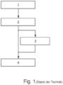
- Fig.1 is a schematic representation of how filter rods with flavor capsules have been manufactured and checked to date.
- filter rods with flavor capsules are manufactured on a filter rod device, for example with a filter rod made of acetate, for example on a filter rod machine according to the KDF sold by the applicant.
- microwave sensors for example the applicant's MIDAS-EF, to determine whether capsules are missing, whether a double number has been inserted in one place, whether a capsule is in the wrong position, whether a capsule is broken or has an irregular fill level.
- the capsules are then optionally stored for 24 hours or more, depending on the customer, and in a process step 2 are fed into a pneumatic conveying device, for example according to the applicant's "FDU" (Filter Detection Unit), which is described, for example, in the German patent application EN 10 2009 017 962 A1
- FDU Fan Detection Unit
- This microwave device also corresponds, for example, to the MIDAS-EF, i.e. a cylindrical microwave resonator with a central passage for longitudinally axially conveyed filter rods, as is the case, for example, with DE 198 54 550 B4 is known.
- multi-filter production takes place, in which capsule-filled filter plugs are combined with other filter plugs to form a multi-filter rod.
- the capsules can be damaged and possibly dry out over a longer period of time.
- testing in process step 2 is not possible due to a lack of appropriate facilities at the manufacturer.
- process step 4 the respective filter is assembled and connected to a tobacco rod on a filter attachment machine, for example the machine sold by the applicant under the name "MAX".
- a filter attachment machine for example the machine sold by the applicant under the name "MAX”.
- a trough conveyor device in the form of a trough drum 10 is shown in detail, on the cylindrical surface of which a sequence of troughs 12 is arranged, which hold cigarettes 14 with suction air (not shown).
- the trough drum 10 moves the cigarettes 14 in a conveying direction 11, which is shown with an arrow.
- the cigarettes 14 consist of a tobacco rod 17, which is mostly held in a trough 12, to which a filter 16 with a capsule 18 inserted therein is attached.
- the trough 12 and the trough drum 10 end approximately in the area of the transition from the tobacco rod 17 to the filter 16, so that a section 15 of the cigarette 14 protrudes over the trough 12 and is conveyed freely. These sections 15 of the cigarettes 14 then pass through a measuring device.
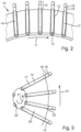
- a trough conveying device in the form of a trough cone drum 20 with a substantially frustroconical circumference.
- the trough cone drum 20 rotates in a conveying direction 21 and has troughs 22 on its outer circumferential surface in which cigarettes 14 are held by means of suction air (not shown).
- suction air not shown
- the protruding sections 15 of the cigarettes 14 dip into a measuring device (not shown).
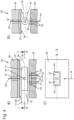
- Fig. 4a shows a cross-section that runs vertically through the conveying trajectory 19 of a cross-axially conveyed cigarette 14 with filter 16 and capsule 18 in the middle of the filter 16. At this point, the cigarette 14 is conveyed with its protruding section 15 through a passage channel 40 of the capacitive HF measuring device 30.
- the Fig. 4a The wall surface shown above consists of an electrically conductive electrode surface 38, which is insulated from the likewise metallic base body 36 of the HF measuring device 30 by means of an insulation 37.
- a supply line 39 runs through the insulation 37, via which the electrode surface 38 is exposed to a harmonic HF signal.
- the part of the capacitive HF measuring device 34 shown below the cigarette 14 comprises, as the underside of the passage channel 40 or the opposite side, the electrically conductive base body 36, which is held at a ground potential, and two capacitor electrodes 42, 42', which are electrically insulated from the base body 36 by means of insulation 43, 43' and are connected to an electrical circuit via leads 44, 44'. These capacitor electrodes 42, 42' are held on a virtual ground. Since the potential between the virtual ground and the ground on which the base body 36 lies only differs by up to approx. 1 mV, a very homogeneous HF measuring field is formed in the entire passage channel 40 between the electrode 38 to which an HF measuring signal is applied and the opposite surface, which lies on ground or virtual ground.
- Fig. 4b the same capacitive HF measuring device 30 is shown in a section, which includes the conveying trajectory 19 of the cigarette 14 or the filter 16 with the capsule 18. Since this is conveyed in a trough on a trough drum in the exemplary embodiment, the passage channel 40 in this area has a ring-section-shaped design or describes a curve whose radius of curvature corresponds to the radius of the trough drum.
- Fig. 4c shows a top view of the lower surface of the passage channel 40, i.e. the side of the capacitive HF measuring device 30 that is held at ground potential.
- a large part of the surface of this electrode consists of the surface of the base body 36 that is held at ground potential.
- Two capacitor electrodes 42, 42' that are held at virtual ground are arranged centrally along the trajectory 19 of a capsule 18.
- the capacitor electrodes 42, 42' are insulated from the base body 36 by a circumferential insulation 43. The actual potential difference, however, is only up to one or a few mV.
- the capacitor electrodes 42, 42' are arranged to the left and right of the trajectory 19, so that incorrect positioning of a capsule can be recognized by an asymmetry in the measurement signals of the capacitor electrodes 42, 42'.
- a first circuit of a capacitive HF measuring device 30 that can be used according to the invention is shown schematically.
- the measuring capacitor 34 is fed by a harmonic signal source, i.e. an oscillator 50.
- the oscillator 50 can be constructed, for example, with a DDS circuit with a downstream low-pass filter or with a quartz oscillator.
- the second connection of the measuring capacitor 34 is connected to the input of a zero detector circuit 62, the input of which is virtually held at ground potential 60 by the causal relationship. Since the input of the zero detector circuit 62 is virtually held at ground potential 60, the existing stray capacitances 54, 56 of the connection lines of the measuring capacitor 34 are ineffective in terms of measurement technology.
- a compensation capacitance or a compensation capacitor 68 is used to improve the resolution of the measurement, which is replaced by an inverting Amplifier 66 is fed from the same oscillator 50 as the measuring capacitor 34.
- the gain factor -a of the inverting amplifier 66 and the capacitance value of the compensation capacitor 68 are selected so that in the measuring range of the measuring capacitor 34 at the input of the zero detector circuit 62, an approximate ground potential is already established when the signal of the oscillator circuit 51 is zero. This avoids having to compensate for a large empty signal of the measuring capacitor 34 with the signal of the oscillator 51. Only the change in the measuring capacitor 34 needs to be compensated. This can significantly improve the resolution of the measurement.
- a further advantage of this compensation circuit is that a significant part of the noise of the oscillator 50 is compensated because the measuring capacitor 34 and the compensation capacitor 68 are fed from the same signal source.
- the zero detector control circuit in the circuit according to Fig.5 the arrangement of zero detector circuit 62, control device 64 and oscillator 51 with impedance 52, which ensure that the virtual ground 60 is established.
- Fig.6 shows a further embodiment of a circuit arrangement that can be used according to the invention.
- two measuring capacitors 34, 34' are connected to a harmonic oscillator 50 as a signal source.
- Both measuring capacitors 34, 34' are the same as in Fig.4 This also means that the two measuring capacitors 39, 39' share the electrode surface 38 which is exposed to an RF measuring signal.
- Stray capacitances and compensation capacitances are shown in Fig.6 not shown, but are as in Fig.5 , present.
- Each measuring capacitor 34, 34' is connected to its own zero detector circuit 62, 62'.
- Each zero detector circuit input is virtually regulated to ground potential 60, 60' by a corresponding control device 64, 64' and oscillators 51, 51' via impedances 52, 52'.
- the corresponding output signals 65a, 65a' of the two control devices 64, 64' are further processed in an evaluation circuit 70.
- this evaluation circuit 70 on the one hand, sum signals are formed which make it possible to detect the presence and the correct content of the capsules.
- a difference signal is formed which is zero when the capsule is correctly positioned in the filter. If the capsule is not in the center position, either a positive or a negative difference signal results depending on the deviation.
- a Fig. 7a shown improved embodiment of an oscillator 50a, which replaces the oscillator 50 in Fig.5 and 6 can be set, the property of DDS components 80 is used to generate complementary output signals U' , -U' . These are connected in opposite directions to the inputs of two differential amplifiers 81, 82. This generates two mutually inverted signals U, - ⁇ U with different amplification factors, namely, for example, an amplification factor of 1 in the differential amplifier 81 and an amplification factor of - ⁇ in the differential amplifier 82.
- the amplification factor ⁇ is usually significantly smaller than 1.
- the measuring capacitor 34 (or 34') is then operated with the output signal U of the differential amplifier 81, and the compensation capacitor 68 is operated with the output signal - ⁇ U of the differential amplifier 82. In this way, a signal generated by the amplifier 66 in Fig.5 caused disturbing additional phase delay between the measuring capacitor 34 and the compensation compensator 68 can be avoided.
- a DDS module 90 can also be used in a similar way in an oscillator 51a according to Fig. 7b ) which replaces the oscillator 51 according to Fig.5 , 6
- the DDS module 90 receives the manipulated variables 65 as an input signal.
- the output signals U', -U' are converted via a differential amplifier 91 into an output signal U, which is fed via an impedance 52, 52' according to Fig.5 , 6 used to set the virtual mass 60, 60'.
Landscapes
- Health & Medical Sciences (AREA)
- General Health & Medical Sciences (AREA)
- Toxicology (AREA)
- Manufacturing Of Cigar And Cigarette Tobacco (AREA)
- Investigating Or Analyzing Materials By The Use Of Electric Means (AREA)
Priority Applications (1)
| Application Number | Priority Date | Filing Date | Title |
|---|---|---|---|
| PL14182569.5T PL2865282T5 (pl) | 2013-09-03 | 2014-08-28 | Układ i sposób do kontroli sztabkowych wyrobów przemysłu tytoniowego |
Applications Claiming Priority (1)
| Application Number | Priority Date | Filing Date | Title |
|---|---|---|---|
| DE102013217485.3A DE102013217485B4 (de) | 2013-09-03 | 2013-09-03 | Anordnung und Verfahren zur Überprüfung von stabförmigen Artikeln der Tabak verarbeitenden Industrie |
Publications (3)
| Publication Number | Publication Date |
|---|---|
| EP2865282A1 EP2865282A1 (de) | 2015-04-29 |
| EP2865282B1 EP2865282B1 (de) | 2018-04-18 |
| EP2865282B2 true EP2865282B2 (de) | 2024-07-24 |
Family
ID=51399567
Family Applications (1)
| Application Number | Title | Priority Date | Filing Date |
|---|---|---|---|
| EP14182569.5A Active EP2865282B2 (de) | 2013-09-03 | 2014-08-28 | Anordnung und Verfahren zur Überprüfung von stabförmigen Artikeln der Tabak verarbeitenden Industrie |
Country Status (5)
| Country | Link |
|---|---|
| EP (1) | EP2865282B2 (pl) |
| JP (1) | JP6442195B2 (pl) |
| CN (1) | CN104413544A (pl) |
| DE (1) | DE102013217485B4 (pl) |
| PL (1) | PL2865282T5 (pl) |
Families Citing this family (3)
| Publication number | Priority date | Publication date | Assignee | Title |
|---|---|---|---|---|
| CN107467714B (zh) * | 2016-06-07 | 2020-08-25 | 贵州中烟工业有限责任公司 | 一种烟卷的检测方法、控制装置及烟卷的检测系统 |
| US11013268B2 (en) | 2017-02-28 | 2021-05-25 | Altria Client Services Llc | Aerosol-generating system with electrodes and sensors |
| RU2736959C2 (ru) * | 2019-12-25 | 2020-11-23 | Хауни Машиненбау Гмбх | Измерительное устройство для вакуумного ленточного транспортера и вакуумный ленточный транспортер с измерительным устройством |
Citations (8)
| Publication number | Priority date | Publication date | Assignee | Title |
|---|---|---|---|---|
| DE2441832A1 (de) † | 1974-08-31 | 1976-03-11 | Hauni Werke Koerber & Co Kg | Verfahren und anordnung zum kapazitiven pruefen der tabakdichte in den enden von stabfoermigen artikeln der tabakverarbeitenden industrie |
| DE3626071A1 (de) † | 1986-08-01 | 1988-02-11 | Hauni Werke Koerber & Co Kg | Verfahren und anordnung zum pruefen von zigaretten oder anderen stabfoermigen gegenstaenden |
| US5767686A (en) † | 1995-03-30 | 1998-06-16 | Fife Corporation | Device for contactless detection of the position of a moving web |
| WO2000005593A1 (en) † | 1998-07-24 | 2000-02-03 | Life Measurement Instruments, Inc. | Variable dielectric position transducer and method |
| WO2002047497A1 (en) † | 2000-12-15 | 2002-06-20 | Philip Morris Products, Inc. | Inspection system |
| US20080084220A1 (en) † | 2004-12-22 | 2008-04-10 | Dierk Schroder | Measuring Apparatus and Method for Recognizing Foreign Bodies in a Product, Particularly Tobacco, Cotton or Another Fibrous Product |
| WO2009099793A2 (en) † | 2008-02-01 | 2009-08-13 | R. J. Reynolds Tobacco Company | System for analyzing a filter element associated with a smoking article, and associated method |
| EP2573553A1 (de) † | 2011-09-20 | 2013-03-27 | HAUNI Maschinenbau AG | Kapazitive HF-Strangmessvorrichtung und Messverfahren |
Family Cites Families (9)
| Publication number | Priority date | Publication date | Assignee | Title |
|---|---|---|---|---|
| DE2343668C2 (de) * | 1973-08-30 | 1985-07-11 | Hauni-Werke Körber & Co KG, 2050 Hamburg | Vorrichtung zum Prüfen der Enden von stabförmigen Tabakartikeln, insbesondere von Zigaretten |
| DE2428567A1 (de) * | 1974-06-14 | 1976-01-02 | Hauni Werke Koerber & Co Kg | Vorrichtung zum pruefen von stabfoermigen tabakartikeln, vorzugsweise von zigaretten |
| GB1474454A (en) * | 1974-09-23 | 1977-05-25 | Gallaher Ltd | Cigarettes |
| DE19854550C5 (de) | 1998-11-26 | 2011-03-17 | Hauni Maschinenbau Ag | Resonatorgehäuse für Mikrowellen |
| DE202005010375U1 (de) * | 2005-07-01 | 2005-10-20 | Tews Elektronik Dipl.-Ing. Manfred Tews | Vorrichtung zum Detektieren und Aussondern von fehlerhaften Zigaretten |
| CH699752A1 (de) * | 2008-10-16 | 2010-04-30 | Uster Technologies Ag | Vorrichtung und verfahren zum ausmessen einer kapazität. |
| DE102009017962A1 (de) | 2009-04-21 | 2010-11-04 | Hauni Maschinenbau Ag | Verfahren und Vorrichtung zur Überprüfung der Qualität von mit Kapseln versehenen Filterstäben |
| CN103502803B (zh) * | 2011-03-11 | 2016-06-29 | 乌斯特技术股份公司 | 用于电容性分析运动测试材料的设备和方法 |
| DE102013213936A1 (de) * | 2013-07-16 | 2015-01-22 | Hauni Maschinenbau Ag | Anordnung und Verfahren zur Überprüfung von stabförmigen Artikeln der Tabak verarbeitenden Industrie |
-
2013
- 2013-09-03 DE DE102013217485.3A patent/DE102013217485B4/de active Active
-
2014
- 2014-08-28 EP EP14182569.5A patent/EP2865282B2/de active Active
- 2014-08-28 PL PL14182569.5T patent/PL2865282T5/pl unknown
- 2014-08-29 JP JP2014174990A patent/JP6442195B2/ja active Active
- 2014-09-03 CN CN201410445308.7A patent/CN104413544A/zh active Pending
Patent Citations (8)
| Publication number | Priority date | Publication date | Assignee | Title |
|---|---|---|---|---|
| DE2441832A1 (de) † | 1974-08-31 | 1976-03-11 | Hauni Werke Koerber & Co Kg | Verfahren und anordnung zum kapazitiven pruefen der tabakdichte in den enden von stabfoermigen artikeln der tabakverarbeitenden industrie |
| DE3626071A1 (de) † | 1986-08-01 | 1988-02-11 | Hauni Werke Koerber & Co Kg | Verfahren und anordnung zum pruefen von zigaretten oder anderen stabfoermigen gegenstaenden |
| US5767686A (en) † | 1995-03-30 | 1998-06-16 | Fife Corporation | Device for contactless detection of the position of a moving web |
| WO2000005593A1 (en) † | 1998-07-24 | 2000-02-03 | Life Measurement Instruments, Inc. | Variable dielectric position transducer and method |
| WO2002047497A1 (en) † | 2000-12-15 | 2002-06-20 | Philip Morris Products, Inc. | Inspection system |
| US20080084220A1 (en) † | 2004-12-22 | 2008-04-10 | Dierk Schroder | Measuring Apparatus and Method for Recognizing Foreign Bodies in a Product, Particularly Tobacco, Cotton or Another Fibrous Product |
| WO2009099793A2 (en) † | 2008-02-01 | 2009-08-13 | R. J. Reynolds Tobacco Company | System for analyzing a filter element associated with a smoking article, and associated method |
| EP2573553A1 (de) † | 2011-09-20 | 2013-03-27 | HAUNI Maschinenbau AG | Kapazitive HF-Strangmessvorrichtung und Messverfahren |
Also Published As
| Publication number | Publication date |
|---|---|
| JP6442195B2 (ja) | 2018-12-19 |
| EP2865282A1 (de) | 2015-04-29 |
| CN104413544A (zh) | 2015-03-18 |
| DE102013217485B4 (de) | 2024-09-26 |
| DE102013217485A1 (de) | 2015-03-05 |
| JP2015047164A (ja) | 2015-03-16 |
| PL2865282T5 (pl) | 2024-10-28 |
| EP2865282B1 (de) | 2018-04-18 |
| PL2865282T3 (pl) | 2018-10-31 |
Similar Documents
| Publication | Publication Date | Title |
|---|---|---|
| EP2848133B1 (de) | Anordnung und Verfahren zur Überprüfung von stabförmigen Artikeln der Tabak verarbeitenden Industrie | |
| EP2207027B1 (de) | Verfahren und Vorrichtung zur Messung der Feuchte von Kapseln in einem Zigarettenfilterstrang, indem dieser durch einen Mikrowellenresonator geführt wird | |
| EP2674044B1 (de) | Verfahren und Vorrichtung zur Erkennung von Stranginhomogenitäten eines Materialstrangs der Tabak verarbeitenden Industrie | |
| DE102013201511B3 (de) | Anordnung und Verfahren zur Überprüfung von stabförmigen Produkten der Tabak verarbeitenden Industrie | |
| EP2965640B1 (de) | Prüfung von stabförmigen artikeln, insbesondere filterzigaretten | |
| EP3158325B1 (de) | Mikrowellenmessvorrichtung, anordnung und verfahren zur überprüfung von stabförmigen artikeln oder eines materialstrangs der tabak verarbeitenden industrie sowie maschine der tabak verarbeitenden industrie | |
| EP1739411B1 (de) | Vorrichtung und Verfahren zum Detektieren und Aussondern von fehlerhaften Zigaretten | |
| DE2755517A1 (de) | Kapazitive vorrichtung zur messung eines fluessigkeitspegels | |
| DE102009017962A1 (de) | Verfahren und Vorrichtung zur Überprüfung der Qualität von mit Kapseln versehenen Filterstäben | |
| EP3497438B1 (de) | Messvorrichtung und verfahren zum erkennen von elektrisch leitenden elementen in produkten sowie eine maschine zum herstellen von produkten der tabak verarbeitenden industrie | |
| EP2433510A2 (de) | Vorrichtung und Verfahren zur Messung von Eigenschaften eines bewegten Materialstrangs, insbesondere Zigarettenstrangs, mittels eine Mikrowellenresonators, dessen Ausgangssignal herabgemischt wird | |
| EP3281536B1 (de) | Verfahren und vorrichtung zum erkennen und/oder prüfen eines in ein stab- oder strangförmiges produkt der tabak verarbeitenden industrie eingelegten objekts | |
| DE102011006414A1 (de) | Verfahren und Vorrichtung zur Ermittlung von Gewichtsanteilen in einem Filtermaterial | |
| EP2657693A2 (de) | Kapazitive HF-Strangmessvorrichtung und Messverfahren | |
| EP2865282B2 (de) | Anordnung und Verfahren zur Überprüfung von stabförmigen Artikeln der Tabak verarbeitenden Industrie | |
| EP2873334B2 (de) | Verfahren und Vorrichtung zur Erkennung von Stranginhomogenitäten eines Materialstrangs der Tabak verarbeitenden Industrie | |
| DE102004063229B4 (de) | Meßvorrichtung und -verfahren zur Erkennung von Fremdkörpern in einem Produkt, insbesondere in Tabak, Baumwolle oder einem anderen Faserprodukt | |
| EP3246671B1 (de) | Kapazitiver sensor und verfahren zur bestimmung der permittivitätsverteilung in einem objekt | |
| EP3176567A1 (de) | Anordnung, maschine, verfahren und verwendung zum überprüfen einer zigarettenkopfqualität | |
| DE102014107747A1 (de) | Messmodul, Messanordnung und Strangmaschine in der Tabak verarbeitenden Industrie |
Legal Events
| Date | Code | Title | Description |
|---|---|---|---|
| PUAI | Public reference made under article 153(3) epc to a published international application that has entered the european phase |
Free format text: ORIGINAL CODE: 0009012 |
|
| 17P | Request for examination filed |
Effective date: 20140828 |
|
| AK | Designated contracting states |
Kind code of ref document: A1 Designated state(s): AL AT BE BG CH CY CZ DE DK EE ES FI FR GB GR HR HU IE IS IT LI LT LU LV MC MK MT NL NO PL PT RO RS SE SI SK SM TR |
|
| AX | Request for extension of the european patent |
Extension state: BA ME |
|
| R17P | Request for examination filed (corrected) |
Effective date: 20150917 |
|
| RBV | Designated contracting states (corrected) |
Designated state(s): AL AT BE BG CH CY CZ DE DK EE ES FI FR GB GR HR HU IE IS IT LI LT LU LV MC MK MT NL NO PL PT RO RS SE SI SK SM TR |
|
| RAP1 | Party data changed (applicant data changed or rights of an application transferred) |
Owner name: HAUNI MASCHINENBAU GMBH |
|
| GRAP | Despatch of communication of intention to grant a patent |
Free format text: ORIGINAL CODE: EPIDOSNIGR1 |
|
| STAA | Information on the status of an ep patent application or granted ep patent |
Free format text: STATUS: GRANT OF PATENT IS INTENDED |
|
| INTG | Intention to grant announced |
Effective date: 20171211 |
|
| GRAS | Grant fee paid |
Free format text: ORIGINAL CODE: EPIDOSNIGR3 |
|
| GRAA | (expected) grant |
Free format text: ORIGINAL CODE: 0009210 |
|
| STAA | Information on the status of an ep patent application or granted ep patent |
Free format text: STATUS: THE PATENT HAS BEEN GRANTED |
|
| AK | Designated contracting states |
Kind code of ref document: B1 Designated state(s): AL AT BE BG CH CY CZ DE DK EE ES FI FR GB GR HR HU IE IS IT LI LT LU LV MC MK MT NL NO PL PT RO RS SE SI SK SM TR |
|
| REG | Reference to a national code |
Ref country code: GB Ref legal event code: FG4D Free format text: NOT ENGLISH |
|
| REG | Reference to a national code |
Ref country code: CH Ref legal event code: EP |
|
| REG | Reference to a national code |
Ref country code: AT Ref legal event code: REF Ref document number: 989448 Country of ref document: AT Kind code of ref document: T Effective date: 20180515 |
|
| REG | Reference to a national code |
Ref country code: IE Ref legal event code: FG4D Free format text: LANGUAGE OF EP DOCUMENT: GERMAN |
|
| REG | Reference to a national code |
Ref country code: DE Ref legal event code: R096 Ref document number: 502014007989 Country of ref document: DE |
|
| REG | Reference to a national code |
Ref country code: NL Ref legal event code: FP |
|
| REG | Reference to a national code |
Ref country code: LT Ref legal event code: MG4D |
|
| PG25 | Lapsed in a contracting state [announced via postgrant information from national office to epo] |
Ref country code: FI Free format text: LAPSE BECAUSE OF FAILURE TO SUBMIT A TRANSLATION OF THE DESCRIPTION OR TO PAY THE FEE WITHIN THE PRESCRIBED TIME-LIMIT Effective date: 20180418 Ref country code: SE Free format text: LAPSE BECAUSE OF FAILURE TO SUBMIT A TRANSLATION OF THE DESCRIPTION OR TO PAY THE FEE WITHIN THE PRESCRIBED TIME-LIMIT Effective date: 20180418 Ref country code: LT Free format text: LAPSE BECAUSE OF FAILURE TO SUBMIT A TRANSLATION OF THE DESCRIPTION OR TO PAY THE FEE WITHIN THE PRESCRIBED TIME-LIMIT Effective date: 20180418 Ref country code: NO Free format text: LAPSE BECAUSE OF FAILURE TO SUBMIT A TRANSLATION OF THE DESCRIPTION OR TO PAY THE FEE WITHIN THE PRESCRIBED TIME-LIMIT Effective date: 20180718 Ref country code: ES Free format text: LAPSE BECAUSE OF FAILURE TO SUBMIT A TRANSLATION OF THE DESCRIPTION OR TO PAY THE FEE WITHIN THE PRESCRIBED TIME-LIMIT Effective date: 20180418 Ref country code: AL Free format text: LAPSE BECAUSE OF FAILURE TO SUBMIT A TRANSLATION OF THE DESCRIPTION OR TO PAY THE FEE WITHIN THE PRESCRIBED TIME-LIMIT Effective date: 20180418 |
|
| PG25 | Lapsed in a contracting state [announced via postgrant information from national office to epo] |
Ref country code: HR Free format text: LAPSE BECAUSE OF FAILURE TO SUBMIT A TRANSLATION OF THE DESCRIPTION OR TO PAY THE FEE WITHIN THE PRESCRIBED TIME-LIMIT Effective date: 20180418 Ref country code: GR Free format text: LAPSE BECAUSE OF FAILURE TO SUBMIT A TRANSLATION OF THE DESCRIPTION OR TO PAY THE FEE WITHIN THE PRESCRIBED TIME-LIMIT Effective date: 20180719 Ref country code: LV Free format text: LAPSE BECAUSE OF FAILURE TO SUBMIT A TRANSLATION OF THE DESCRIPTION OR TO PAY THE FEE WITHIN THE PRESCRIBED TIME-LIMIT Effective date: 20180418 Ref country code: RS Free format text: LAPSE BECAUSE OF FAILURE TO SUBMIT A TRANSLATION OF THE DESCRIPTION OR TO PAY THE FEE WITHIN THE PRESCRIBED TIME-LIMIT Effective date: 20180418 |
|
| PG25 | Lapsed in a contracting state [announced via postgrant information from national office to epo] |
Ref country code: PT Free format text: LAPSE BECAUSE OF FAILURE TO SUBMIT A TRANSLATION OF THE DESCRIPTION OR TO PAY THE FEE WITHIN THE PRESCRIBED TIME-LIMIT Effective date: 20180820 |
|
| REG | Reference to a national code |
Ref country code: DE Ref legal event code: R026 Ref document number: 502014007989 Country of ref document: DE |
|
| PLBI | Opposition filed |
Free format text: ORIGINAL CODE: 0009260 |
|
| PG25 | Lapsed in a contracting state [announced via postgrant information from national office to epo] |
Ref country code: RO Free format text: LAPSE BECAUSE OF FAILURE TO SUBMIT A TRANSLATION OF THE DESCRIPTION OR TO PAY THE FEE WITHIN THE PRESCRIBED TIME-LIMIT Effective date: 20180418 Ref country code: CZ Free format text: LAPSE BECAUSE OF FAILURE TO SUBMIT A TRANSLATION OF THE DESCRIPTION OR TO PAY THE FEE WITHIN THE PRESCRIBED TIME-LIMIT Effective date: 20180418 Ref country code: DK Free format text: LAPSE BECAUSE OF FAILURE TO SUBMIT A TRANSLATION OF THE DESCRIPTION OR TO PAY THE FEE WITHIN THE PRESCRIBED TIME-LIMIT Effective date: 20180418 Ref country code: EE Free format text: LAPSE BECAUSE OF FAILURE TO SUBMIT A TRANSLATION OF THE DESCRIPTION OR TO PAY THE FEE WITHIN THE PRESCRIBED TIME-LIMIT Effective date: 20180418 Ref country code: SK Free format text: LAPSE BECAUSE OF FAILURE TO SUBMIT A TRANSLATION OF THE DESCRIPTION OR TO PAY THE FEE WITHIN THE PRESCRIBED TIME-LIMIT Effective date: 20180418 |
|
| PLAX | Notice of opposition and request to file observation + time limit sent |
Free format text: ORIGINAL CODE: EPIDOSNOBS2 |
|
| 26 | Opposition filed |
Opponent name: G.D S.P.A. Effective date: 20190117 |
|
| PG25 | Lapsed in a contracting state [announced via postgrant information from national office to epo] |
Ref country code: SM Free format text: LAPSE BECAUSE OF FAILURE TO SUBMIT A TRANSLATION OF THE DESCRIPTION OR TO PAY THE FEE WITHIN THE PRESCRIBED TIME-LIMIT Effective date: 20180418 |
|
| PG25 | Lapsed in a contracting state [announced via postgrant information from national office to epo] |
Ref country code: MC Free format text: LAPSE BECAUSE OF FAILURE TO SUBMIT A TRANSLATION OF THE DESCRIPTION OR TO PAY THE FEE WITHIN THE PRESCRIBED TIME-LIMIT Effective date: 20180418 |
|
| GBPC | Gb: european patent ceased through non-payment of renewal fee |
Effective date: 20180828 |
|
| PG25 | Lapsed in a contracting state [announced via postgrant information from national office to epo] |
Ref country code: LU Free format text: LAPSE BECAUSE OF NON-PAYMENT OF DUE FEES Effective date: 20180828 |
|
| REG | Reference to a national code |
Ref country code: BE Ref legal event code: MM Effective date: 20180831 |
|
| PLBB | Reply of patent proprietor to notice(s) of opposition received |
Free format text: ORIGINAL CODE: EPIDOSNOBS3 |
|
| PG25 | Lapsed in a contracting state [announced via postgrant information from national office to epo] |
Ref country code: SI Free format text: LAPSE BECAUSE OF FAILURE TO SUBMIT A TRANSLATION OF THE DESCRIPTION OR TO PAY THE FEE WITHIN THE PRESCRIBED TIME-LIMIT Effective date: 20180418 |
|
| PG25 | Lapsed in a contracting state [announced via postgrant information from national office to epo] |
Ref country code: FR Free format text: LAPSE BECAUSE OF NON-PAYMENT OF DUE FEES Effective date: 20180831 Ref country code: BE Free format text: LAPSE BECAUSE OF NON-PAYMENT OF DUE FEES Effective date: 20180831 |
|
| PG25 | Lapsed in a contracting state [announced via postgrant information from national office to epo] |
Ref country code: GB Free format text: LAPSE BECAUSE OF NON-PAYMENT OF DUE FEES Effective date: 20180828 |
|
| PG25 | Lapsed in a contracting state [announced via postgrant information from national office to epo] |
Ref country code: MT Free format text: LAPSE BECAUSE OF FAILURE TO SUBMIT A TRANSLATION OF THE DESCRIPTION OR TO PAY THE FEE WITHIN THE PRESCRIBED TIME-LIMIT Effective date: 20180418 |
|
| PG25 | Lapsed in a contracting state [announced via postgrant information from national office to epo] |
Ref country code: TR Free format text: LAPSE BECAUSE OF FAILURE TO SUBMIT A TRANSLATION OF THE DESCRIPTION OR TO PAY THE FEE WITHIN THE PRESCRIBED TIME-LIMIT Effective date: 20180418 |
|
| PG25 | Lapsed in a contracting state [announced via postgrant information from national office to epo] |
Ref country code: HU Free format text: LAPSE BECAUSE OF FAILURE TO SUBMIT A TRANSLATION OF THE DESCRIPTION OR TO PAY THE FEE WITHIN THE PRESCRIBED TIME-LIMIT; INVALID AB INITIO Effective date: 20140828 |
|
| PG25 | Lapsed in a contracting state [announced via postgrant information from national office to epo] |
Ref country code: IE Free format text: LAPSE BECAUSE OF NON-PAYMENT OF DUE FEES Effective date: 20180828 Ref country code: CY Free format text: LAPSE BECAUSE OF FAILURE TO SUBMIT A TRANSLATION OF THE DESCRIPTION OR TO PAY THE FEE WITHIN THE PRESCRIBED TIME-LIMIT Effective date: 20180418 Ref country code: MK Free format text: LAPSE BECAUSE OF NON-PAYMENT OF DUE FEES Effective date: 20180418 |
|
| PG25 | Lapsed in a contracting state [announced via postgrant information from national office to epo] |
Ref country code: IS Free format text: LAPSE BECAUSE OF FAILURE TO SUBMIT A TRANSLATION OF THE DESCRIPTION OR TO PAY THE FEE WITHIN THE PRESCRIBED TIME-LIMIT Effective date: 20180818 |
|
| REG | Reference to a national code |
Ref country code: AT Ref legal event code: MM01 Ref document number: 989448 Country of ref document: AT Kind code of ref document: T Effective date: 20190828 |
|
| PG25 | Lapsed in a contracting state [announced via postgrant information from national office to epo] |
Ref country code: AT Free format text: LAPSE BECAUSE OF NON-PAYMENT OF DUE FEES Effective date: 20190828 |
|
| PLCK | Communication despatched that opposition was rejected |
Free format text: ORIGINAL CODE: EPIDOSNREJ1 |
|
| APAH | Appeal reference modified |
Free format text: ORIGINAL CODE: EPIDOSCREFNO |
|
| APBM | Appeal reference recorded |
Free format text: ORIGINAL CODE: EPIDOSNREFNO |
|
| APBP | Date of receipt of notice of appeal recorded |
Free format text: ORIGINAL CODE: EPIDOSNNOA2O |
|
| APBQ | Date of receipt of statement of grounds of appeal recorded |
Free format text: ORIGINAL CODE: EPIDOSNNOA3O |
|
| REG | Reference to a national code |
Ref country code: DE Ref legal event code: R081 Ref document number: 502014007989 Country of ref document: DE Owner name: KOERBER TECHNOLOGIES GMBH, DE Free format text: FORMER OWNER: HAUNI MASCHINENBAU GMBH, 21033 HAMBURG, DE |
|
| REG | Reference to a national code |
Ref country code: NL Ref legal event code: HC Owner name: KOERBER TECHNOLOGIES GMBH; DE Free format text: DETAILS ASSIGNMENT: CHANGE OF OWNER(S), CHANGE OF OWNER(S) NAME; FORMER OWNER NAME: HAUNI MASCHINENBAU GMBH Effective date: 20221025 |
|
| RAP4 | Party data changed (patent owner data changed or rights of a patent transferred) |
Owner name: KOERBER TECHNOLOGIES GMBH |
|
| P01 | Opt-out of the competence of the unified patent court (upc) registered |
Effective date: 20230616 |
|
| APBU | Appeal procedure closed |
Free format text: ORIGINAL CODE: EPIDOSNNOA9O |
|
| 27A | Patent maintained in amended form |
Effective date: 20240724 |
|
| AK | Designated contracting states |
Kind code of ref document: B2 Designated state(s): AL AT BE BG CH CY CZ DE DK EE ES FI FR GB GR HR HU IE IS IT LI LT LU LV MC MK MT NL NO PL PT RO RS SE SI SK SM TR |
|
| REG | Reference to a national code |
Ref country code: DE Ref legal event code: R102 Ref document number: 502014007989 Country of ref document: DE |
|
| REG | Reference to a national code |
Ref country code: NL Ref legal event code: FP |
|
| PGFP | Annual fee paid to national office [announced via postgrant information from national office to epo] |
Ref country code: NL Payment date: 20250826 Year of fee payment: 12 |
|
| PGFP | Annual fee paid to national office [announced via postgrant information from national office to epo] |
Ref country code: DE Payment date: 20250821 Year of fee payment: 12 |
|
| PGFP | Annual fee paid to national office [announced via postgrant information from national office to epo] |
Ref country code: IT Payment date: 20250827 Year of fee payment: 12 Ref country code: PL Payment date: 20250722 Year of fee payment: 12 |
|
| PGFP | Annual fee paid to national office [announced via postgrant information from national office to epo] |
Ref country code: BG Payment date: 20250829 Year of fee payment: 12 |
|
| PGFP | Annual fee paid to national office [announced via postgrant information from national office to epo] |
Ref country code: CH Payment date: 20250901 Year of fee payment: 12 |