EP2862947B1 - Method of continuous annealing of steel strip, and method of manufacturing hot-dip galvanized steel strip - Google Patents
Method of continuous annealing of steel strip, and method of manufacturing hot-dip galvanized steel strip Download PDFInfo
- Publication number
- EP2862947B1 EP2862947B1 EP13804997.8A EP13804997A EP2862947B1 EP 2862947 B1 EP2862947 B1 EP 2862947B1 EP 13804997 A EP13804997 A EP 13804997A EP 2862947 B1 EP2862947 B1 EP 2862947B1
- Authority
- EP
- European Patent Office
- Prior art keywords
- furnace
- gas
- steel strip
- annealing
- dew point
- Prior art date
- Legal status (The legal status is an assumption and is not a legal conclusion. Google has not performed a legal analysis and makes no representation as to the accuracy of the status listed.)
- Active
Links
Images
Classifications
-
- C—CHEMISTRY; METALLURGY
- C21—METALLURGY OF IRON
- C21D—MODIFYING THE PHYSICAL STRUCTURE OF FERROUS METALS; GENERAL DEVICES FOR HEAT TREATMENT OF FERROUS OR NON-FERROUS METALS OR ALLOYS; MAKING METAL MALLEABLE, e.g. BY DECARBURISATION OR TEMPERING
- C21D9/00—Heat treatment, e.g. annealing, hardening, quenching or tempering, adapted for particular articles; Furnaces therefor
- C21D9/52—Heat treatment, e.g. annealing, hardening, quenching or tempering, adapted for particular articles; Furnaces therefor for wires; for strips ; for rods of unlimited length
- C21D9/54—Furnaces for treating strips or wire
- C21D9/663—Bell-type furnaces
-
- C—CHEMISTRY; METALLURGY
- C21—METALLURGY OF IRON
- C21D—MODIFYING THE PHYSICAL STRUCTURE OF FERROUS METALS; GENERAL DEVICES FOR HEAT TREATMENT OF FERROUS OR NON-FERROUS METALS OR ALLOYS; MAKING METAL MALLEABLE, e.g. BY DECARBURISATION OR TEMPERING
- C21D1/00—General methods or devices for heat treatment, e.g. annealing, hardening, quenching or tempering
- C21D1/26—Methods of annealing
-
- C—CHEMISTRY; METALLURGY
- C21—METALLURGY OF IRON
- C21D—MODIFYING THE PHYSICAL STRUCTURE OF FERROUS METALS; GENERAL DEVICES FOR HEAT TREATMENT OF FERROUS OR NON-FERROUS METALS OR ALLOYS; MAKING METAL MALLEABLE, e.g. BY DECARBURISATION OR TEMPERING
- C21D1/00—General methods or devices for heat treatment, e.g. annealing, hardening, quenching or tempering
- C21D1/74—Methods of treatment in inert gas, controlled atmosphere, vacuum or pulverulent material
- C21D1/76—Adjusting the composition of the atmosphere
-
- C—CHEMISTRY; METALLURGY
- C21—METALLURGY OF IRON
- C21D—MODIFYING THE PHYSICAL STRUCTURE OF FERROUS METALS; GENERAL DEVICES FOR HEAT TREATMENT OF FERROUS OR NON-FERROUS METALS OR ALLOYS; MAKING METAL MALLEABLE, e.g. BY DECARBURISATION OR TEMPERING
- C21D9/00—Heat treatment, e.g. annealing, hardening, quenching or tempering, adapted for particular articles; Furnaces therefor
- C21D9/52—Heat treatment, e.g. annealing, hardening, quenching or tempering, adapted for particular articles; Furnaces therefor for wires; for strips ; for rods of unlimited length
- C21D9/54—Furnaces for treating strips or wire
- C21D9/56—Continuous furnaces for strip or wire
- C21D9/561—Continuous furnaces for strip or wire with a controlled atmosphere or vacuum
-
- C—CHEMISTRY; METALLURGY
- C21—METALLURGY OF IRON
- C21D—MODIFYING THE PHYSICAL STRUCTURE OF FERROUS METALS; GENERAL DEVICES FOR HEAT TREATMENT OF FERROUS OR NON-FERROUS METALS OR ALLOYS; MAKING METAL MALLEABLE, e.g. BY DECARBURISATION OR TEMPERING
- C21D9/00—Heat treatment, e.g. annealing, hardening, quenching or tempering, adapted for particular articles; Furnaces therefor
- C21D9/52—Heat treatment, e.g. annealing, hardening, quenching or tempering, adapted for particular articles; Furnaces therefor for wires; for strips ; for rods of unlimited length
- C21D9/54—Furnaces for treating strips or wire
- C21D9/56—Continuous furnaces for strip or wire
- C21D9/562—Details
-
- C—CHEMISTRY; METALLURGY
- C22—METALLURGY; FERROUS OR NON-FERROUS ALLOYS; TREATMENT OF ALLOYS OR NON-FERROUS METALS
- C22C—ALLOYS
- C22C38/00—Ferrous alloys, e.g. steel alloys
-
- C—CHEMISTRY; METALLURGY
- C22—METALLURGY; FERROUS OR NON-FERROUS ALLOYS; TREATMENT OF ALLOYS OR NON-FERROUS METALS
- C22C—ALLOYS
- C22C38/00—Ferrous alloys, e.g. steel alloys
- C22C38/02—Ferrous alloys, e.g. steel alloys containing silicon
-
- C—CHEMISTRY; METALLURGY
- C22—METALLURGY; FERROUS OR NON-FERROUS ALLOYS; TREATMENT OF ALLOYS OR NON-FERROUS METALS
- C22C—ALLOYS
- C22C38/00—Ferrous alloys, e.g. steel alloys
- C22C38/04—Ferrous alloys, e.g. steel alloys containing manganese
-
- C—CHEMISTRY; METALLURGY
- C22—METALLURGY; FERROUS OR NON-FERROUS ALLOYS; TREATMENT OF ALLOYS OR NON-FERROUS METALS
- C22C—ALLOYS
- C22C38/00—Ferrous alloys, e.g. steel alloys
- C22C38/06—Ferrous alloys, e.g. steel alloys containing aluminium
-
- C—CHEMISTRY; METALLURGY
- C22—METALLURGY; FERROUS OR NON-FERROUS ALLOYS; TREATMENT OF ALLOYS OR NON-FERROUS METALS
- C22C—ALLOYS
- C22C38/00—Ferrous alloys, e.g. steel alloys
- C22C38/18—Ferrous alloys, e.g. steel alloys containing chromium
- C22C38/40—Ferrous alloys, e.g. steel alloys containing chromium with nickel
- C22C38/58—Ferrous alloys, e.g. steel alloys containing chromium with nickel with more than 1.5% by weight of manganese
-
- C—CHEMISTRY; METALLURGY
- C23—COATING METALLIC MATERIAL; COATING MATERIAL WITH METALLIC MATERIAL; CHEMICAL SURFACE TREATMENT; DIFFUSION TREATMENT OF METALLIC MATERIAL; COATING BY VACUUM EVAPORATION, BY SPUTTERING, BY ION IMPLANTATION OR BY CHEMICAL VAPOUR DEPOSITION, IN GENERAL; INHIBITING CORROSION OF METALLIC MATERIAL OR INCRUSTATION IN GENERAL
- C23C—COATING METALLIC MATERIAL; COATING MATERIAL WITH METALLIC MATERIAL; SURFACE TREATMENT OF METALLIC MATERIAL BY DIFFUSION INTO THE SURFACE, BY CHEMICAL CONVERSION OR SUBSTITUTION; COATING BY VACUUM EVAPORATION, BY SPUTTERING, BY ION IMPLANTATION OR BY CHEMICAL VAPOUR DEPOSITION, IN GENERAL
- C23C2/00—Hot-dipping or immersion processes for applying the coating material in the molten state without affecting the shape; Apparatus therefor
- C23C2/003—Apparatus
- C23C2/0038—Apparatus characterised by the pre-treatment chambers located immediately upstream of the bath or occurring locally before the dipping process
- C23C2/004—Snouts
-
- C—CHEMISTRY; METALLURGY
- C23—COATING METALLIC MATERIAL; COATING MATERIAL WITH METALLIC MATERIAL; CHEMICAL SURFACE TREATMENT; DIFFUSION TREATMENT OF METALLIC MATERIAL; COATING BY VACUUM EVAPORATION, BY SPUTTERING, BY ION IMPLANTATION OR BY CHEMICAL VAPOUR DEPOSITION, IN GENERAL; INHIBITING CORROSION OF METALLIC MATERIAL OR INCRUSTATION IN GENERAL
- C23C—COATING METALLIC MATERIAL; COATING MATERIAL WITH METALLIC MATERIAL; SURFACE TREATMENT OF METALLIC MATERIAL BY DIFFUSION INTO THE SURFACE, BY CHEMICAL CONVERSION OR SUBSTITUTION; COATING BY VACUUM EVAPORATION, BY SPUTTERING, BY ION IMPLANTATION OR BY CHEMICAL VAPOUR DEPOSITION, IN GENERAL
- C23C2/00—Hot-dipping or immersion processes for applying the coating material in the molten state without affecting the shape; Apparatus therefor
- C23C2/02—Pretreatment of the material to be coated, e.g. for coating on selected surface areas
- C23C2/022—Pretreatment of the material to be coated, e.g. for coating on selected surface areas by heating
- C23C2/0224—Two or more thermal pretreatments
-
- C—CHEMISTRY; METALLURGY
- C23—COATING METALLIC MATERIAL; COATING MATERIAL WITH METALLIC MATERIAL; CHEMICAL SURFACE TREATMENT; DIFFUSION TREATMENT OF METALLIC MATERIAL; COATING BY VACUUM EVAPORATION, BY SPUTTERING, BY ION IMPLANTATION OR BY CHEMICAL VAPOUR DEPOSITION, IN GENERAL; INHIBITING CORROSION OF METALLIC MATERIAL OR INCRUSTATION IN GENERAL
- C23C—COATING METALLIC MATERIAL; COATING MATERIAL WITH METALLIC MATERIAL; SURFACE TREATMENT OF METALLIC MATERIAL BY DIFFUSION INTO THE SURFACE, BY CHEMICAL CONVERSION OR SUBSTITUTION; COATING BY VACUUM EVAPORATION, BY SPUTTERING, BY ION IMPLANTATION OR BY CHEMICAL VAPOUR DEPOSITION, IN GENERAL
- C23C2/00—Hot-dipping or immersion processes for applying the coating material in the molten state without affecting the shape; Apparatus therefor
- C23C2/04—Hot-dipping or immersion processes for applying the coating material in the molten state without affecting the shape; Apparatus therefor characterised by the coating material
- C23C2/06—Zinc or cadmium or alloys based thereon
-
- C—CHEMISTRY; METALLURGY
- C23—COATING METALLIC MATERIAL; COATING MATERIAL WITH METALLIC MATERIAL; CHEMICAL SURFACE TREATMENT; DIFFUSION TREATMENT OF METALLIC MATERIAL; COATING BY VACUUM EVAPORATION, BY SPUTTERING, BY ION IMPLANTATION OR BY CHEMICAL VAPOUR DEPOSITION, IN GENERAL; INHIBITING CORROSION OF METALLIC MATERIAL OR INCRUSTATION IN GENERAL
- C23C—COATING METALLIC MATERIAL; COATING MATERIAL WITH METALLIC MATERIAL; SURFACE TREATMENT OF METALLIC MATERIAL BY DIFFUSION INTO THE SURFACE, BY CHEMICAL CONVERSION OR SUBSTITUTION; COATING BY VACUUM EVAPORATION, BY SPUTTERING, BY ION IMPLANTATION OR BY CHEMICAL VAPOUR DEPOSITION, IN GENERAL
- C23C2/00—Hot-dipping or immersion processes for applying the coating material in the molten state without affecting the shape; Apparatus therefor
- C23C2/34—Hot-dipping or immersion processes for applying the coating material in the molten state without affecting the shape; Apparatus therefor characterised by the shape of the material to be treated
- C23C2/36—Elongated material
- C23C2/40—Plates; Strips
Definitions
- the present invention relates to a method for continuously annealing a steel strip and a method for manufacturing a galvanized steel strip.
- high-strength steel high-tensile steel
- the technology of high-tensile steel may possibly be capable of manufacturing a high-strength steel strip with good stretch flangeability by adding Si to steel and suggests the possibility that a steel strip with good ductility can be provided because retained ⁇ is likely to be formed when Si or Al is contained.
- a potential way to avoid the problem is to control the oxygen potential in an annealing atmosphere.
- Patent Literature 1 discloses a method for increasing the oxygen potential in such a way that the dew point of a region from the rear end of a heating zone to an soaking zone is controlled to a high dew point of -30°C or higher.
- This method has the advantage that the method produces some effect and it is industrially easy to adjust the dew point to the high dew point.
- the method has a disadvantage that it is not easy to manufacture the type of steel which is unsuitable for operation at a high dew points (for example, Ti-IF steel). This is because it takes a very long time to change the annealing atmosphere from a high dew point to a low dew point.
- the method produces an oxidizing furnace atmosphere, and incorrect operation results in pick-up defects due to the deposition of an oxides on rollers in the furnace or damage to furnace wall.
- Another potential way is to control the oxygen potential to be low.
- Si, Mn, and the like are very oxidizable, it is very difficult to stably create an atmosphere having a low dew point of -40°C or lower which is excellent in suppressing the oxidation of Si, Mn, and the like in such a large-size continuous annealing furnace in a CGL (continuous galvanizing line) or a CAL (continuous annealing line).
- Patent Literatures 2 and 3 disclose techniques for efficiently achieving an annealing atmosphere with a low dew point. These techniques are applied to relatively small-size furnaces such as one-path vertical furnaces and do not take into account that a steel strip containing an easily oxidizable element such as Si or Mn is annealed in a multi-path vertical annealing furnace such as a CGL or a CAL.
- patent literature 4 disclosed a method for continuously annealing a steel strip wherein a wall is employed to separate the furnace into a heating zone and a reduction zone. The reduction is adjusted to be with a dew point ⁇ -20° in 600-900°C.
- the method has less of a problem with the occurrence of pick-up defects or a problem with the damage of furnace walls; prevents easily oxidizable elements, such as Si and Mn, in steel from being enriched on surfaces of a steel strip to prevent the formation of oxides of the easily oxidizable elements, such as Si and Mn; and can form an annealing atmosphere having a low dew point which is suitable for annealing a steel strip containing a easily oxidizable element such as Si or Mn.
- an annealing atmosphere having a low dew point which is suitable for annealing a steel strip containing an easily oxidizable element such as Si or Mn can be achieved at low cost in such a way that the mixing of an atmosphere in a temperature range where a reduction reaction proceeds and an atmosphere in a temperature range where surface enrichment proceeds is suppressed by providing a gas injector having a plurality of gas outlets arranged in the direction of travel of the steel strip.
- the present invention can improve platability in hot-dip galvanizing of a steel strip which contains an easily oxidizable element such as Si or Mn.
- the surface enrichment level of an easily oxidizable element which significantly affects platability, increases with an increase in steel strip temperature or dew point and the degree of influence thereof varies significantly depending on an element contained in a steel strip.
- the generation of water by reduction occurs mostly within the range of 500°C to 600°C and the surface enrichment of a Si series or a Mn series is problematic at a temperature of 700°C or higher or 800°C or higher, respectively, when the dew point is high. From such a fact, the inventors have reached a conclusion that an atmosphere suitable for ensuring platability is readily obtained by suppressing a mixing of an atmosphere in a temperature range where a reduction reaction proceeds and an atmosphere in a temperature range where surface enrichment proceeds.
- the dew point of the high temperature-side atmosphere can be reduced in such a way that, within a furnace gas discharged into a refiner, an amount of the furnace gas downstream of the gas injector is adjusted to be larger than an amount of the furnace gas upstream of the gas injector.
- the reduction of the dew point in the furnace downstream of the gas injector is insufficient even if the amount of the furnace gas downstream of the gas injector is controlled to be larger than the amount of the furnace gas upstream of the gas injector.
- an atmosphere with a lower dew point can be achieved by combining a suppression of mixing of atmospheres by a non-contact process such as gas sealing, a discharge of gas into the refiner, and a discharge of gas from the refiner.
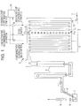
- Fig. 1 shows an example of the configuration of a continuous galvanizing line, including a vertical annealing furnace used to carry out the present invention, for steel strips.
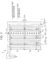
- Fig. 2 shows an example of the arrangement of gas suction (vents) ports going to a refiner and outlets of gas coming from the refiner disposed in a heating zone and in a soaking zone of the annealing furnace. The present invention is described below with reference to Figs. 1 and 2 .
- the continuous galvanizing line includes a multi-path vertical annealing furnace 2 upstream of a plating bath 7.
- a heating zone 3, a soaking zone 4, and a cooling zone 5 are arranged in the annealing furnace 2 in that order from the upstream side to the downstream side of the furnace.
- a gas injector 11 having a plurality of outlets 11a that arranged in the direction of a travel of a steel strip and discharger gas is disposed within a space spanning from the heating zone 3 to the soaking zone 4.
- the discharge direction of the gas is not particularly limited.
- the discharge direction of the gas is preferably horizontal because the effect of suppressing the mixing of atmospheres in the furnace is large.
- the gas injector 11 suppresses the mixing of the furnace atmosphere upstream of the gas injector 11 and the furnace atmosphere downstream of the gas injector 11.
- the outlets 11a discharge gas over an entire width of the furnace in a width direction of the furnace.
- the width direction of the furnace coincides with a width direction of the steel strip.
- the number of the outlets 11a is preferably large.
- the outlets 11a are preferably arranged at an interval of at least 4 m or less in the direction of travel of the steel strip.
- the flow rate at each outlet is preferably 25 Nm 3 /hr or more. When the intervals in the direction of travel of the steel strip is more than 4 m or the flow rate at each outlet is less than 25 Nm 3 /hr, the suppression of the mixing of the atmospheres may possibly be insufficient.
- Discharge gas may include the gas discharged from the refiner of the furnace, gas with a dew point lower than the dew point in the furnace to be set such as an N 2 gas with a dew point of -60°C.
- Reference numeral 14 represents a thermometer that measures the temperature of the steel strip passing in front of the gas injector 11.
- the annealing furnace 2 is connected to the plating bath 7 through a snout 6.
- the inside of the furnace that ranges from the heating zone 3 to the snout 6 is maintained in a reducing atmosphere gas or a non-oxidizing atmosphere.
- the heating zone 3 and the soaking zone 4 indirectly heat the steel strip 1 using radiant tubes (RTs) acting as heating means.
- RTs radiant tubes
- the reducing atmosphere gas used is usually an H 2 -N 2 gas and is introduced into an appropriate site of the inside of the furnace that ranges from the heating zone 3 to the snout 6.
- the gas introduced into the furnace is discharged from the entry side of the furnace except inevitable portions such as furnace leaks.
- the gas in the furnace flows from the downstream side to the upstream side of the furnace against the direction of travel of the steel strip and is discharged outside of the furnace through an opening 13 located on the entry side of the furnace.
- a location where the steel strip 1 passes in front of the gas injector 11 is preferably positioned away from the opening 13 located on the entry side of the furnace through which the gas in the furnace is discharged as far as possible.
- the location where the steel strip 1 passes in front of the gas injector-11 is positioned furthest away from the opening 13, which is located on the entry side of the furnace.
- the refiner 15 is disposed outside of the furnace.
- the refiner 15 includes a deoxygenator and a dehumidifier and is configured such that a part of the atmosphere gas in the furnace is discharged to the refiner 15, the dew point is reduced by removing oxygen and moisture from the gas and the gas with a lowered dew point is discharged into the furnace.
- the refiner may be a known one.
- the gas suction ports going to the refiner and the gas discharge ports coming from the refiner are arranged in appropriate positions upstream and downstream of the gas injector 11, which is disposed within a space spanning from the heating zone to the soaking zone.
- the gas suction ports going to the refiner are arranged in the heating zone so as to be placed in three different sites in the height direction of the furnace and are arranged at six different sites in the soaking zone so as to be placed in the length direction and in the height direction of the furnace.
- the length direction of the furnace is a horizontal direction in Fig. 2 .
- Each of the gas discharge ports coming from the refiner is placed 0.5 m below corresponding one of the suction ports. The amount of gas sucked from each of the suction ports and the amount of gas discharged from each of the discharge ports can be individually adjusted in terms of flow rates.
- the control of the temperature of the steel strip passing in front of the gas injector 11 is very important.
- the temperature at which reduction proceeds is 500°C to 600°C and the temperature at which surface enrichment proceeds is 700°C or higher or 800°C or higher in the case of the Si or Mn series, respectively. Since the temperature at which reduction proceeds and the temperature at which surface enrichment proceeds are close to each other, effects of the present invention are not exhibited and opposite effects may possibly be caused if temperature control is not adequate.
- the temperature of the steel strip passing in front of the gas injector 11 is controlled within the range of 600°C to 700°C.
- the temperature of the steel strip is lower than 600°C, the steel strip is conveyed to a high-temperature side downstream of the gas injector in an insufficiently reduced state. Therefore, a large amount of gas due to reduction is generated on the high-temperature side and the dew point on the high-temperature side is increased, thereby impairing the wettability.
- the temperature of the steel strip is higher than 700°C, surface enrichment proceeds on a low-temperature side upstream of the gas injector 11 having a high dew point, and the platability is impaired.
- the temperature of the steel strip passing in front of the gas injector 11 can be controlled by adjusting the heating capacity, the burning capacity, or the like of the RTs.
- the platability of a Si- or Mn-containing steel strip can be enhanced without using the refiner. Furthermore, the use of the refiner enables the dew point of gas in the furnace to be reduced and also enables the platability to be enhanced.
- the gas going to the refiner may be discharged from the low-temperature side upstream of the gas injector 11 or the high-temperature side downstream of the gas injector 11.
- the gas going to the refiner is preferably discharged such that the amount of gas discharged from downstream of the gas injector 11 is larger than the amount of gas discharged from upstream of the gas injector 11.
- the temperature of the steel strip passing in front of the gas injector 11 is within the range of 600°C to 700°C or even when the temperature thereof is within a range wider than the above range on a low-temperature side, that is, the range of, for example, 550°C to 700°C, effects of the present invention can be achieved.
- the temperature of the steel strip passing in front of the gas injector 11 is controlled within the range of 550°C to 700°C and the gas going to the refiner is discharged such that the amount of gas discharged from downstream of the gas injector 11 is larger than the amount of gas discharged from upstream of the gas injector 11.
- the steel strip is annealed in the heating zone 3 and the soaking zone 4 in a predetermined manner, is cooled in the cooling zone 5, is immersed in the plating bath 7 through the snout 6, and is thereby galvanized and the coating weight is adjusted to a predetermined coating weight with wiping nozzles 8, whereby a galvanized steel strip is obtained.
- a zinc coating is alloyed using a heater 9.
- the steel strip annealed by a method according to the present invention can be enhanced in platability by galvanizing because the surface enrichment of easily oxidizable elements such as Si and Mn is suppressed. Effects of the present invention are exhibited when the steel strip contains 0.4% to 2.0% by mass of Si and/or 1% to 3% by mass of Mn.
- C, Al, S, P, and the like are contained.
- the content of each typical component is as follows: the content of C is 0.01% to 0.18%, the content of Al is 0.001% to 1.0%, the content of P is 0.005% to 0.060%, and the content of S is 0.01% or less on a mass basis.
- At least one selected from the group consisting of 0.001% to 0.005% of B, 0.005% to 0.05% of Nb, 0.005% to 0.05% of Ti, 0.001% to 1.0% of Cr, 0.05% to 1.0% of Mo, 0.05% to 1.0% of Cu, and 0.05% to 1.0% of Ni may be added as required.
- the steel strip is introduced from a lower portion of the furnace.
- the steel strip may be introduced from the upper side of the furnace.
- the steel strip travels above the gas injector 11.
- the steel strip may travel under the gas injector 11.
- the soaking zone and the heating zone communicate with each other through an upper portion of the furnace.
- the soaking zone and the heating zone may communicate with each other through a lower portion of the furnace.
- no preheater is placed upstream of the heating zone.
- the annealing furnace may include a preheater.
- An annealing method according to the present invention can be applied to an annealing method used in a continuous annealing line (CAL) for steel strips.
- CAL continuous annealing line
- Steel strips were galvanized in an ART (all-radiant tube) CGL including a gas injector that is disposed within a space spanning from a heating zone and a soaking zone to suppress the mixing of an atmosphere in the furnace and a refiner that is disposed outside of the furnace and includes a dehumidifier and a deoxygenator as shown in Figs. 1 and 2 in such a way that atmosphere conditions in the furnace were varied and the dew points were measured, whereby galvanized steel strips were manufactured and the platabilities were evaluated.
- ART all-radiant tube
- the length (the horizontal length in Fig. 2 ) from the heating zone to the soaking zone was 16 m.
- the length of the heating zone was 6 m.
- the length of the soaking zone was 10 m.
- the gas injector was located 6 m apart from an entry-side wall of the furnace.
- a refiner gas (a dew point of -60°C, 500°C, a dehumidified furnace gas) was discharged from the gas injector ( ⁇ 50 mm outlets arranged in 14 sites at intervals of 1.4 m in the direction of travel of the steel strips).
- Sites for supplying an atmosphere gas from outside of the furnace were arranged in the soaking zone in nine positions at each of 1 m above a drive-side hearth and 10 m above the drive-side hearth along the length direction of the furnace and totaled 18.
- the supplied atmosphere gas had a dew point of -60°C to -70°C and was an H 2 -N 2 gas (an H 2 concentration of 10% by volume).
- FIG. 2 Gas suction ports going to the refiner and gas discharge ports coming from the refiner were as shown in Fig. 2 .
- Discharge ports A to I were located 0.5 m down from the suction ports A to I (suction/discharge from one side wall of the furnace).
- the gas suction ports going to the refiner were ⁇ 200 mm and the discharge ports were ⁇ 50 mm.
- Other specifications such as flow rate were as shown in Table 2.
- the dehumidifier contained a synthetic zeolite and the deoxygenator contained a palladium catalyst.
- Cold-rolled steel strips (three types of steels A to C shown in Table 1) having a thickness of 0.8 mm to 1.2 mm and a width of 950 mm to 1,000 mm were used and were tested under conditions as common as possible such that the annealing temperature was 820°C and the feed rate was 100 mpm to 120 mpm.
- the dew point was investigated after the refiner was used for 1 hr.
- the dew points were measured at the same position as those of gas suction ports (however, on the side of the furnace wall opposite to the suction port).
- examples of the present invention have a lower dew point as compared to comparative examples and are improved in platability.
- an annealing atmosphere having a low dew point which is suitable for annealing a steel strip containing an easily oxidizable element such as Si or Mn can be achieved at low cost in such a way that the mixing of an atmosphere in a temperature range where a reduction reaction proceeds and an atmosphere in a temperature range where surface enrichment proceeds is suppressed by providing a gas injector having a plurality of gas discharge ports arranged in the direction of travel of the steel strip.
- the platability of a steel strip which contains an easily oxidizable element such as Si or Mn and which is galvanized can be improved.
Landscapes
- Chemical & Material Sciences (AREA)
- Engineering & Computer Science (AREA)
- Organic Chemistry (AREA)
- Materials Engineering (AREA)
- Mechanical Engineering (AREA)
- Metallurgy (AREA)
- Chemical Kinetics & Catalysis (AREA)
- Physics & Mathematics (AREA)
- Thermal Sciences (AREA)
- Crystallography & Structural Chemistry (AREA)
- Heat Treatment Of Strip Materials And Filament Materials (AREA)
- Coating With Molten Metal (AREA)
- Furnace Details (AREA)
Applications Claiming Priority (2)
| Application Number | Priority Date | Filing Date | Title |
|---|---|---|---|
| JP2012133616 | 2012-06-13 | ||
| PCT/JP2013/003634 WO2013187042A1 (ja) | 2012-06-13 | 2013-06-10 | 鋼帯の連続焼鈍方法および溶融亜鉛めっき鋼帯の製造方法 |
Publications (3)
| Publication Number | Publication Date |
|---|---|
| EP2862947A1 EP2862947A1 (en) | 2015-04-22 |
| EP2862947A4 EP2862947A4 (en) | 2015-07-15 |
| EP2862947B1 true EP2862947B1 (en) | 2018-08-08 |
Family
ID=49757888
Family Applications (1)
| Application Number | Title | Priority Date | Filing Date |
|---|---|---|---|
| EP13804997.8A Active EP2862947B1 (en) | 2012-06-13 | 2013-06-10 | Method of continuous annealing of steel strip, and method of manufacturing hot-dip galvanized steel strip |
Country Status (6)
| Country | Link |
|---|---|
| US (1) | US10106867B2 (zh) |
| EP (1) | EP2862947B1 (zh) |
| JP (1) | JP5655956B2 (zh) |
| KR (1) | KR101642633B1 (zh) |
| CN (1) | CN104379777B (zh) |
| WO (1) | WO2013187042A1 (zh) |
Families Citing this family (5)
| Publication number | Priority date | Publication date | Assignee | Title |
|---|---|---|---|---|
| EP2835432B1 (en) * | 2012-04-06 | 2016-11-02 | JFE Steel Corporation | Continuous hot-dip zinc plating facility |
| JP5790898B1 (ja) * | 2013-11-07 | 2015-10-07 | Jfeスチール株式会社 | 連続焼鈍設備および連続焼鈍方法 |
| CN109652639B (zh) * | 2018-12-29 | 2024-02-09 | 佛山市诚德新材料有限公司 | 一种不锈钢带的退火炉 |
| BE1026986B1 (fr) * | 2019-01-23 | 2020-08-25 | Drever Int S A | Procédé et four pour le traitement thermique d’une bande d’acier de haute résistance comprenant une chambre d’homogénéisation en température |
| FR3095452A1 (fr) * | 2019-04-29 | 2020-10-30 | Fives Stein | Ligne de traitement en continu de bandes métalliques à double usage |
Family Cites Families (16)
| Publication number | Priority date | Publication date | Assignee | Title |
|---|---|---|---|---|
| JP2670134B2 (ja) | 1989-03-08 | 1997-10-29 | 川崎製鉄株式会社 | ステンレス鋼帯の竪型連続光輝焼鈍炉における雰囲気ガス制御方法 |
| JP2567130B2 (ja) | 1990-05-07 | 1996-12-25 | 日本冶金工業株式会社 | 光輝焼鈍炉 |
| JP2567140B2 (ja) | 1990-09-04 | 1996-12-25 | 日本冶金工業株式会社 | 光輝焼鈍炉 |
| JPH07116526B2 (ja) * | 1991-04-18 | 1995-12-13 | 川崎製鉄株式会社 | 連続熱処理炉 |
| JP2567130Y2 (ja) | 1992-03-16 | 1998-03-30 | 矢崎総業株式会社 | ブスバー固定構造 |
| JP2567140Y2 (ja) | 1992-09-17 | 1998-03-30 | 弘 丹羽 | フィッシングゲームマシン |
| JP2974888B2 (ja) * | 1993-06-30 | 1999-11-10 | 川崎製鉄株式会社 | 雰囲気炉の非接触式シール装置 |
| JP3176843B2 (ja) * | 1996-06-05 | 2001-06-18 | 川崎製鉄株式会社 | 溶融亜鉛めっき鋼板の製造方法および製造設備 |
| JPH09324210A (ja) * | 1996-06-07 | 1997-12-16 | Kawasaki Steel Corp | 溶融亜鉛めっき鋼板の製造方法および製造設備 |
| JPH10176225A (ja) * | 1996-12-13 | 1998-06-30 | Daido Steel Co Ltd | 金属ストリップの連続焼鈍炉 |
| JP2000290762A (ja) * | 1999-04-07 | 2000-10-17 | Kawasaki Steel Corp | 溶融めっき鋼板の製造方法 |
| JP2003129125A (ja) * | 2001-10-15 | 2003-05-08 | Daido Steel Co Ltd | ストリップ連続熱処理炉 |
| JP4791482B2 (ja) | 2005-10-14 | 2011-10-12 | 新日本製鐵株式会社 | Siを含有する鋼板の連続焼鈍溶融めっき方法及び連続焼鈍溶融めっき装置 |
| JP4770428B2 (ja) * | 2005-11-29 | 2011-09-14 | Jfeスチール株式会社 | 高強度溶融亜鉛めっき鋼板の製造方法および溶融亜鉛めっき鋼板の製造設備 |
| JP2011046988A (ja) * | 2009-08-26 | 2011-03-10 | Daido Steel Co Ltd | 金属ストリップの連続焼鈍炉 |
| JP5712542B2 (ja) * | 2010-09-29 | 2015-05-07 | Jfeスチール株式会社 | 高強度鋼板およびその製造方法 |
-
2013
- 2013-06-10 KR KR1020147035449A patent/KR101642633B1/ko active IP Right Grant
- 2013-06-10 US US14/405,077 patent/US10106867B2/en active Active
- 2013-06-10 WO PCT/JP2013/003634 patent/WO2013187042A1/ja active Application Filing
- 2013-06-10 EP EP13804997.8A patent/EP2862947B1/en active Active
- 2013-06-10 CN CN201380031150.2A patent/CN104379777B/zh active Active
- 2013-06-10 JP JP2013543075A patent/JP5655956B2/ja active Active
Non-Patent Citations (1)
| Title |
|---|
| None * |
Also Published As
| Publication number | Publication date |
|---|---|
| JPWO2013187042A1 (ja) | 2016-02-04 |
| US20150159235A1 (en) | 2015-06-11 |
| WO2013187042A1 (ja) | 2013-12-19 |
| US10106867B2 (en) | 2018-10-23 |
| EP2862947A1 (en) | 2015-04-22 |
| CN104379777B (zh) | 2017-10-10 |
| KR101642633B1 (ko) | 2016-07-25 |
| KR20150013829A (ko) | 2015-02-05 |
| EP2862947A4 (en) | 2015-07-15 |
| CN104379777A (zh) | 2015-02-25 |
| JP5655956B2 (ja) | 2015-01-21 |
Similar Documents
| Publication | Publication Date | Title |
|---|---|---|
| EP2653572B1 (en) | Method for continuously annealing steel strip and hot-dip galvanization method | |
| US9759491B2 (en) | Continuous annealing furnace for annealing steel strip, method for continuously annealing steel strip, continuous hot-dip galvanizing facility, and method for manufacturing hot-dip galvanized steel strip | |
| EP2862946B1 (en) | Method for continuously annealing steel strip, apparatus for continuously annealing steel strip, method for manufacturing hot-dip galvanized steel strip, and apparatus for manufacturing hot-dip galvanized steel strip | |
| EP2806043B1 (en) | Continuous annealing furnace and continuous annealing method for steel strips | |
| JP5884748B2 (ja) | 鋼帯の連続焼鈍装置および連続溶融亜鉛めっき装置 | |
| EP2862947B1 (en) | Method of continuous annealing of steel strip, and method of manufacturing hot-dip galvanized steel strip | |
| JP5338087B2 (ja) | めっき性に優れる溶融亜鉛めっき鋼板の製造方法および連続溶融亜鉛めっき設備 | |
| JP5565485B1 (ja) | 鋼帯の連続焼鈍装置および連続溶融亜鉛めっき装置 | |
| EP3067434B1 (en) | Continuous annealing equipment and continuous annealing method |
Legal Events
| Date | Code | Title | Description |
|---|---|---|---|
| PUAI | Public reference made under article 153(3) epc to a published international application that has entered the european phase |
Free format text: ORIGINAL CODE: 0009012 |
|
| 17P | Request for examination filed |
Effective date: 20150113 |
|
| AK | Designated contracting states |
Kind code of ref document: A1 Designated state(s): AL AT BE BG CH CY CZ DE DK EE ES FI FR GB GR HR HU IE IS IT LI LT LU LV MC MK MT NL NO PL PT RO RS SE SI SK SM TR |
|
| AX | Request for extension of the european patent |
Extension state: BA ME |
|
| RA4 | Supplementary search report drawn up and despatched (corrected) |
Effective date: 20150617 |
|
| RIC1 | Information provided on ipc code assigned before grant |
Ipc: C23C 2/02 20060101ALI20150611BHEP Ipc: C22C 38/06 20060101ALI20150611BHEP Ipc: C23C 2/40 20060101ALI20150611BHEP Ipc: C23C 2/06 20060101ALI20150611BHEP Ipc: C22C 38/58 20060101ALI20150611BHEP Ipc: C21D 1/76 20060101ALI20150611BHEP Ipc: C21D 9/56 20060101AFI20150611BHEP Ipc: C22C 38/00 20060101ALI20150611BHEP |
|
| DAX | Request for extension of the european patent (deleted) | ||
| STAA | Information on the status of an ep patent application or granted ep patent |
Free format text: STATUS: EXAMINATION IS IN PROGRESS |
|
| 17Q | First examination report despatched |
Effective date: 20161102 |
|
| GRAP | Despatch of communication of intention to grant a patent |
Free format text: ORIGINAL CODE: EPIDOSNIGR1 |
|
| STAA | Information on the status of an ep patent application or granted ep patent |
Free format text: STATUS: GRANT OF PATENT IS INTENDED |
|
| INTG | Intention to grant announced |
Effective date: 20180122 |
|
| GRAS | Grant fee paid |
Free format text: ORIGINAL CODE: EPIDOSNIGR3 |
|
| GRAA | (expected) grant |
Free format text: ORIGINAL CODE: 0009210 |
|
| STAA | Information on the status of an ep patent application or granted ep patent |
Free format text: STATUS: THE PATENT HAS BEEN GRANTED |
|
| AK | Designated contracting states |
Kind code of ref document: B1 Designated state(s): AL AT BE BG CH CY CZ DE DK EE ES FI FR GB GR HR HU IE IS IT LI LT LU LV MC MK MT NL NO PL PT RO RS SE SI SK SM TR |
|
| REG | Reference to a national code |
Ref country code: GB Ref legal event code: FG4D |
|
| REG | Reference to a national code |
Ref country code: CH Ref legal event code: EP Ref country code: AT Ref legal event code: REF Ref document number: 1027087 Country of ref document: AT Kind code of ref document: T Effective date: 20180815 |
|
| REG | Reference to a national code |
Ref country code: IE Ref legal event code: FG4D |
|
| REG | Reference to a national code |
Ref country code: DE Ref legal event code: R096 Ref document number: 602013041746 Country of ref document: DE |
|
| REG | Reference to a national code |
Ref country code: NL Ref legal event code: MP Effective date: 20180808 |
|
| REG | Reference to a national code |
Ref country code: LT Ref legal event code: MG4D |
|
| REG | Reference to a national code |
Ref country code: AT Ref legal event code: MK05 Ref document number: 1027087 Country of ref document: AT Kind code of ref document: T Effective date: 20180808 |
|
| PG25 | Lapsed in a contracting state [announced via postgrant information from national office to epo] |
Ref country code: NO Free format text: LAPSE BECAUSE OF FAILURE TO SUBMIT A TRANSLATION OF THE DESCRIPTION OR TO PAY THE FEE WITHIN THE PRESCRIBED TIME-LIMIT Effective date: 20181108 Ref country code: GR Free format text: LAPSE BECAUSE OF FAILURE TO SUBMIT A TRANSLATION OF THE DESCRIPTION OR TO PAY THE FEE WITHIN THE PRESCRIBED TIME-LIMIT Effective date: 20181109 Ref country code: AT Free format text: LAPSE BECAUSE OF FAILURE TO SUBMIT A TRANSLATION OF THE DESCRIPTION OR TO PAY THE FEE WITHIN THE PRESCRIBED TIME-LIMIT Effective date: 20180808 Ref country code: NL Free format text: LAPSE BECAUSE OF FAILURE TO SUBMIT A TRANSLATION OF THE DESCRIPTION OR TO PAY THE FEE WITHIN THE PRESCRIBED TIME-LIMIT Effective date: 20180808 Ref country code: IS Free format text: LAPSE BECAUSE OF FAILURE TO SUBMIT A TRANSLATION OF THE DESCRIPTION OR TO PAY THE FEE WITHIN THE PRESCRIBED TIME-LIMIT Effective date: 20181208 Ref country code: BG Free format text: LAPSE BECAUSE OF FAILURE TO SUBMIT A TRANSLATION OF THE DESCRIPTION OR TO PAY THE FEE WITHIN THE PRESCRIBED TIME-LIMIT Effective date: 20181108 Ref country code: FI Free format text: LAPSE BECAUSE OF FAILURE TO SUBMIT A TRANSLATION OF THE DESCRIPTION OR TO PAY THE FEE WITHIN THE PRESCRIBED TIME-LIMIT Effective date: 20180808 Ref country code: LT Free format text: LAPSE BECAUSE OF FAILURE TO SUBMIT A TRANSLATION OF THE DESCRIPTION OR TO PAY THE FEE WITHIN THE PRESCRIBED TIME-LIMIT Effective date: 20180808 Ref country code: RS Free format text: LAPSE BECAUSE OF FAILURE TO SUBMIT A TRANSLATION OF THE DESCRIPTION OR TO PAY THE FEE WITHIN THE PRESCRIBED TIME-LIMIT Effective date: 20180808 Ref country code: PL Free format text: LAPSE BECAUSE OF FAILURE TO SUBMIT A TRANSLATION OF THE DESCRIPTION OR TO PAY THE FEE WITHIN THE PRESCRIBED TIME-LIMIT Effective date: 20180808 Ref country code: SE Free format text: LAPSE BECAUSE OF FAILURE TO SUBMIT A TRANSLATION OF THE DESCRIPTION OR TO PAY THE FEE WITHIN THE PRESCRIBED TIME-LIMIT Effective date: 20180808 |
|
| PG25 | Lapsed in a contracting state [announced via postgrant information from national office to epo] |
Ref country code: AL Free format text: LAPSE BECAUSE OF FAILURE TO SUBMIT A TRANSLATION OF THE DESCRIPTION OR TO PAY THE FEE WITHIN THE PRESCRIBED TIME-LIMIT Effective date: 20180808 Ref country code: LV Free format text: LAPSE BECAUSE OF FAILURE TO SUBMIT A TRANSLATION OF THE DESCRIPTION OR TO PAY THE FEE WITHIN THE PRESCRIBED TIME-LIMIT Effective date: 20180808 Ref country code: HR Free format text: LAPSE BECAUSE OF FAILURE TO SUBMIT A TRANSLATION OF THE DESCRIPTION OR TO PAY THE FEE WITHIN THE PRESCRIBED TIME-LIMIT Effective date: 20180808 |
|
| PG25 | Lapsed in a contracting state [announced via postgrant information from national office to epo] |
Ref country code: EE Free format text: LAPSE BECAUSE OF FAILURE TO SUBMIT A TRANSLATION OF THE DESCRIPTION OR TO PAY THE FEE WITHIN THE PRESCRIBED TIME-LIMIT Effective date: 20180808 Ref country code: IT Free format text: LAPSE BECAUSE OF FAILURE TO SUBMIT A TRANSLATION OF THE DESCRIPTION OR TO PAY THE FEE WITHIN THE PRESCRIBED TIME-LIMIT Effective date: 20180808 Ref country code: ES Free format text: LAPSE BECAUSE OF FAILURE TO SUBMIT A TRANSLATION OF THE DESCRIPTION OR TO PAY THE FEE WITHIN THE PRESCRIBED TIME-LIMIT Effective date: 20180808 Ref country code: CZ Free format text: LAPSE BECAUSE OF FAILURE TO SUBMIT A TRANSLATION OF THE DESCRIPTION OR TO PAY THE FEE WITHIN THE PRESCRIBED TIME-LIMIT Effective date: 20180808 Ref country code: RO Free format text: LAPSE BECAUSE OF FAILURE TO SUBMIT A TRANSLATION OF THE DESCRIPTION OR TO PAY THE FEE WITHIN THE PRESCRIBED TIME-LIMIT Effective date: 20180808 |
|
| REG | Reference to a national code |
Ref country code: DE Ref legal event code: R097 Ref document number: 602013041746 Country of ref document: DE |
|
| PG25 | Lapsed in a contracting state [announced via postgrant information from national office to epo] |
Ref country code: SM Free format text: LAPSE BECAUSE OF FAILURE TO SUBMIT A TRANSLATION OF THE DESCRIPTION OR TO PAY THE FEE WITHIN THE PRESCRIBED TIME-LIMIT Effective date: 20180808 Ref country code: DK Free format text: LAPSE BECAUSE OF FAILURE TO SUBMIT A TRANSLATION OF THE DESCRIPTION OR TO PAY THE FEE WITHIN THE PRESCRIBED TIME-LIMIT Effective date: 20180808 Ref country code: SK Free format text: LAPSE BECAUSE OF FAILURE TO SUBMIT A TRANSLATION OF THE DESCRIPTION OR TO PAY THE FEE WITHIN THE PRESCRIBED TIME-LIMIT Effective date: 20180808 |
|
| PLBE | No opposition filed within time limit |
Free format text: ORIGINAL CODE: 0009261 |
|
| STAA | Information on the status of an ep patent application or granted ep patent |
Free format text: STATUS: NO OPPOSITION FILED WITHIN TIME LIMIT |
|
| 26N | No opposition filed |
Effective date: 20190509 |
|
| PG25 | Lapsed in a contracting state [announced via postgrant information from national office to epo] |
Ref country code: SI Free format text: LAPSE BECAUSE OF FAILURE TO SUBMIT A TRANSLATION OF THE DESCRIPTION OR TO PAY THE FEE WITHIN THE PRESCRIBED TIME-LIMIT Effective date: 20180808 |
|
| PGFP | Annual fee paid to national office [announced via postgrant information from national office to epo] |
Ref country code: GB Payment date: 20190627 Year of fee payment: 7 |
|
| PG25 | Lapsed in a contracting state [announced via postgrant information from national office to epo] |
Ref country code: MC Free format text: LAPSE BECAUSE OF FAILURE TO SUBMIT A TRANSLATION OF THE DESCRIPTION OR TO PAY THE FEE WITHIN THE PRESCRIBED TIME-LIMIT Effective date: 20180808 |
|
| REG | Reference to a national code |
Ref country code: CH Ref legal event code: PL |
|
| REG | Reference to a national code |
Ref country code: BE Ref legal event code: MM Effective date: 20190630 |
|
| PG25 | Lapsed in a contracting state [announced via postgrant information from national office to epo] |
Ref country code: TR Free format text: LAPSE BECAUSE OF FAILURE TO SUBMIT A TRANSLATION OF THE DESCRIPTION OR TO PAY THE FEE WITHIN THE PRESCRIBED TIME-LIMIT Effective date: 20180808 |
|
| PG25 | Lapsed in a contracting state [announced via postgrant information from national office to epo] |
Ref country code: IE Free format text: LAPSE BECAUSE OF NON-PAYMENT OF DUE FEES Effective date: 20190610 |
|
| PG25 | Lapsed in a contracting state [announced via postgrant information from national office to epo] |
Ref country code: LU Free format text: LAPSE BECAUSE OF NON-PAYMENT OF DUE FEES Effective date: 20190610 Ref country code: LI Free format text: LAPSE BECAUSE OF NON-PAYMENT OF DUE FEES Effective date: 20190630 Ref country code: BE Free format text: LAPSE BECAUSE OF NON-PAYMENT OF DUE FEES Effective date: 20190630 Ref country code: CH Free format text: LAPSE BECAUSE OF NON-PAYMENT OF DUE FEES Effective date: 20190630 |
|
| PG25 | Lapsed in a contracting state [announced via postgrant information from national office to epo] |
Ref country code: PT Free format text: LAPSE BECAUSE OF FAILURE TO SUBMIT A TRANSLATION OF THE DESCRIPTION OR TO PAY THE FEE WITHIN THE PRESCRIBED TIME-LIMIT Effective date: 20181208 |
|
| GBPC | Gb: european patent ceased through non-payment of renewal fee |
Effective date: 20200610 |
|
| PG25 | Lapsed in a contracting state [announced via postgrant information from national office to epo] |
Ref country code: GB Free format text: LAPSE BECAUSE OF NON-PAYMENT OF DUE FEES Effective date: 20200610 |
|
| PG25 | Lapsed in a contracting state [announced via postgrant information from national office to epo] |
Ref country code: CY Free format text: LAPSE BECAUSE OF FAILURE TO SUBMIT A TRANSLATION OF THE DESCRIPTION OR TO PAY THE FEE WITHIN THE PRESCRIBED TIME-LIMIT Effective date: 20180808 |
|
| PG25 | Lapsed in a contracting state [announced via postgrant information from national office to epo] |
Ref country code: MT Free format text: LAPSE BECAUSE OF FAILURE TO SUBMIT A TRANSLATION OF THE DESCRIPTION OR TO PAY THE FEE WITHIN THE PRESCRIBED TIME-LIMIT Effective date: 20180808 Ref country code: HU Free format text: LAPSE BECAUSE OF FAILURE TO SUBMIT A TRANSLATION OF THE DESCRIPTION OR TO PAY THE FEE WITHIN THE PRESCRIBED TIME-LIMIT; INVALID AB INITIO Effective date: 20130610 |
|
| PG25 | Lapsed in a contracting state [announced via postgrant information from national office to epo] |
Ref country code: MK Free format text: LAPSE BECAUSE OF FAILURE TO SUBMIT A TRANSLATION OF THE DESCRIPTION OR TO PAY THE FEE WITHIN THE PRESCRIBED TIME-LIMIT Effective date: 20180808 |
|
| PGFP | Annual fee paid to national office [announced via postgrant information from national office to epo] |
Ref country code: FR Payment date: 20230510 Year of fee payment: 11 Ref country code: DE Payment date: 20230502 Year of fee payment: 11 |