EP2862746A1 - Vehicle seat - Google Patents
Vehicle seat Download PDFInfo
- Publication number
- EP2862746A1 EP2862746A1 EP20140189152 EP14189152A EP2862746A1 EP 2862746 A1 EP2862746 A1 EP 2862746A1 EP 20140189152 EP20140189152 EP 20140189152 EP 14189152 A EP14189152 A EP 14189152A EP 2862746 A1 EP2862746 A1 EP 2862746A1
- Authority
- EP
- European Patent Office
- Prior art keywords
- support body
- seat
- fixed
- occupant
- movable
- Prior art date
- Legal status (The legal status is an assumption and is not a legal conclusion. Google has not performed a legal analysis and makes no representation as to the accuracy of the status listed.)
- Granted
Links
Images


Classifications
-
- B—PERFORMING OPERATIONS; TRANSPORTING
- B60—VEHICLES IN GENERAL
- B60N—SEATS SPECIALLY ADAPTED FOR VEHICLES; VEHICLE PASSENGER ACCOMMODATION NOT OTHERWISE PROVIDED FOR
- B60N2/00—Seats specially adapted for vehicles; Arrangement or mounting of seats in vehicles
- B60N2/58—Seat coverings
- B60N2/5816—Seat coverings attachments thereof
- B60N2/5825—Seat coverings attachments thereof by hooks, staples, clips, snap fasteners or the like
-
- B—PERFORMING OPERATIONS; TRANSPORTING
- B60—VEHICLES IN GENERAL
- B60N—SEATS SPECIALLY ADAPTED FOR VEHICLES; VEHICLE PASSENGER ACCOMMODATION NOT OTHERWISE PROVIDED FOR
- B60N2/00—Seats specially adapted for vehicles; Arrangement or mounting of seats in vehicles
- B60N2/64—Back-rests or cushions
- B60N2/646—Back-rests or cushions shape of the cushion
-
- B—PERFORMING OPERATIONS; TRANSPORTING
- B60—VEHICLES IN GENERAL
- B60N—SEATS SPECIALLY ADAPTED FOR VEHICLES; VEHICLE PASSENGER ACCOMMODATION NOT OTHERWISE PROVIDED FOR
- B60N2/00—Seats specially adapted for vehicles; Arrangement or mounting of seats in vehicles
- B60N2/70—Upholstery springs ; Upholstery
- B60N2/7094—Upholstery springs
-
- B—PERFORMING OPERATIONS; TRANSPORTING
- B60—VEHICLES IN GENERAL
- B60N—SEATS SPECIALLY ADAPTED FOR VEHICLES; VEHICLE PASSENGER ACCOMMODATION NOT OTHERWISE PROVIDED FOR
- B60N2/00—Seats specially adapted for vehicles; Arrangement or mounting of seats in vehicles
- B60N2/70—Upholstery springs ; Upholstery
- B60N2/72—Attachment or adjustment thereof
-
- B—PERFORMING OPERATIONS; TRANSPORTING
- B60—VEHICLES IN GENERAL
- B60N—SEATS SPECIALLY ADAPTED FOR VEHICLES; VEHICLE PASSENGER ACCOMMODATION NOT OTHERWISE PROVIDED FOR
- B60N2/00—Seats specially adapted for vehicles; Arrangement or mounting of seats in vehicles
- B60N2/90—Details or parts not otherwise provided for
- B60N2/986—Side-rests
-
- B—PERFORMING OPERATIONS; TRANSPORTING
- B60—VEHICLES IN GENERAL
- B60N—SEATS SPECIALLY ADAPTED FOR VEHICLES; VEHICLE PASSENGER ACCOMMODATION NOT OTHERWISE PROVIDED FOR
- B60N2/00—Seats specially adapted for vehicles; Arrangement or mounting of seats in vehicles
- B60N2/02—Seats specially adapted for vehicles; Arrangement or mounting of seats in vehicles the seat or part thereof being movable, e.g. adjustable
- B60N2002/0204—Seats specially adapted for vehicles; Arrangement or mounting of seats in vehicles the seat or part thereof being movable, e.g. adjustable characterised by the seat or seat part turning about or moving along a non-standard, particular axis, i.e. an axis different from the axis characterising the conventional movement
- B60N2002/0208—Seats specially adapted for vehicles; Arrangement or mounting of seats in vehicles the seat or part thereof being movable, e.g. adjustable characterised by the seat or seat part turning about or moving along a non-standard, particular axis, i.e. an axis different from the axis characterising the conventional movement the seat or seat part turning about or moving along an inclined axis
-
- B—PERFORMING OPERATIONS; TRANSPORTING
- B60—VEHICLES IN GENERAL
- B60N—SEATS SPECIALLY ADAPTED FOR VEHICLES; VEHICLE PASSENGER ACCOMMODATION NOT OTHERWISE PROVIDED FOR
- B60N2/00—Seats specially adapted for vehicles; Arrangement or mounting of seats in vehicles
- B60N2/02—Seats specially adapted for vehicles; Arrangement or mounting of seats in vehicles the seat or part thereof being movable, e.g. adjustable
- B60N2002/0204—Seats specially adapted for vehicles; Arrangement or mounting of seats in vehicles the seat or part thereof being movable, e.g. adjustable characterised by the seat or seat part turning about or moving along a non-standard, particular axis, i.e. an axis different from the axis characterising the conventional movement
- B60N2002/022—Seats specially adapted for vehicles; Arrangement or mounting of seats in vehicles the seat or part thereof being movable, e.g. adjustable characterised by the seat or seat part turning about or moving along a non-standard, particular axis, i.e. an axis different from the axis characterising the conventional movement the seat or seat part turning about or moving along a vertical axis
Definitions
- the invention relates to a conveyance seat including a seat frame serving as a frame that supports a load of a seated occupant, and a seat pad that is disposed on the seat frame, and flexibly receives the load of the seated occupant.
- Japanese Patent No. 4095583 describes a seat that allows a seated occupant to easily change his or her seated posture.
- a seat cushion is able to be swung in a right-left direction with respect to a base member on a vehicle floor.
- the occupant can easily swing his or her body in the right-left direction while remaining in the seated posture.
- it is possible to promote blood circulation in the body to suppress an increase in the degree of tiredness.
- the entire seat cushion is able to be swung in the right-left direction with respect to the base member, and therefore, the seated posture of the occupant is unstable, and thus, the seat is not comfortable.
- the invention provides a conveyance seat that holds the body of an occupant and allows the occupant to partially move his or her body easily so that the seated posture of the occupant is stably maintained and blood circulation in the body is promoted to suppress an increase in the degree of tiredness.
- An aspect of the invention relates to a conveyance seat including: a seat frame serving as a frame that supports a load of a seated occupant; and a seat pad that is disposed on the seat frame, and flexibly receives the load of the seated occupant.
- the conveyance seat includes a support body disposed based on a center portion of a distribution of a sitting pressure applied by the seated occupant to.the seat pad. In the conveyance seat, the support body is supported with respect'to the seat frame such that a front end portion of the support body is rotatable in a right-left.
- the seat pad includes a fixed portion that is supported at a fixed position by the seat frame, and a movable portion that is supported by the support body such that the movable portion is movable.
- the fixed portion of the seat pad is supported, at the fixed position by the seat frame, and therefore, the seated posture of the occupant can be stably maintained by the fixed portion of the seat pad.
- the movable portion of the seat pad is supported by the support body such that the movable portion is movable, and therefore, the occupant can easily swing his or her body while remaining in the seated posture.
- the pelvis is turned about a portion near the lumbar spine, and a sitting pressure is changed. Accordingly, blood circulation in the body is promoted to suppress an ingrease in the degree of tiredness.
- the support body may include a spring body that is stretched and contracted along a support plane of the support body.
- the support body since the support body includes the spring body, the support body can be used also as a spring body required in the seat frame. Further, since the support body includes the spring body, when a phase deviation occurs between the rotation angle of the front end portion of the support body and the moved position of the rear end portion of the support body, or when the front end portion is rotated and the rear end portion is linearly moved, the spring body can absorb the deviation.
- a cut portion that allows the movable portion to move in accordance with movement of the support body may be provided at a border portion between the fixed portion and the movable portion of the seat pad.
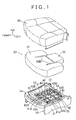
- a first embodiment of the invention will be described with reference to FIG. 1 to FIG. 6 :
- the invention is applied to a seat cushion of a front seat of a vehicle.
- arrows indicate directions when the seat is provided in the vehicle.
- the seat cushion is formed by disposing a cushion pad 20 (that may be regarded as a seat pad according to the invention) that flexibly receives a load of a seated occupant, on a cushion frame 10 (that may be regarded as a seat frame according to the invention) serving as a frame that supports the load of the seated occupant, and covering the cushion frame 10 and the cushion pad 20 with a cushion cover 30, as in a known vehicle seat in related art.
- the basic structure of the seat cushion is the same as that of a known seat cushion in related art, and thus, detailed illustration and description of the basic structure of the seat cushion will be omitted.
- the cushion frame 10 is formed by connecting a cushion panel 14 and a rear pipe 13 to right and left side frames 12, 11 by welding.
- the cushion panel 14 is welded to front ends of the right and left side frames 12, 11.
- the cushion panel 14, and upper end surfaces of the side frames 11, 12 form a surface that supports the cushion pad 20.
- a tilted portion 14A is provided in a portion in a rear side of the cushion panel 14, the portion being located between the right and left side frames 12, 11.
- the tilted portion 14A is tilted downward in a rearward direction.
- a swinging piece 41 with a substantially triangle shape is fitted to a center portion of the tilted portion 14A in a right-left direction with use of a stepped hinge pin 41 A such that the swinging piece 41 is able to be swung (rotated) in the right-left direction.
- the swinging piece 41 is swung (rotated) in the right-left direction about a rotation axis that is perpendicular to the tilted portion 14A.
- the swinging piece 41 is supported such that the swinging piece 41 is able to be swung (rotated) in the right-left direction about the straight line tilted upward in a direction from the front side toward the rear side.
- the swinging piece 41 i.e., a front end portion of a support body 40 to be described later
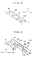
- a portion of the swinging piece 41 which is located at a bottom side of the triangle shape, is bent to extend rearward in a horizontal direction. Portions of the plate surface of the bent portion are cut and raised to form four spring receivers 41B.
- the four spring receivers 41B are arranged in the right-left direction. Front ends of four S-shaped springs 42 (that may be regarded as a spring body according to the invention) engage with the respective spring receivers 41B.
- a fixed bracket 44 is fixed, by welding, to a center portion of the rear pipe 13 in the right-left direction.
- An extended portion of the fixed bracket 44 which is disposed behind the rear pipe 13, extends downward.
- a spring bracket 43 is fitted to the extended portion of the fixed bracket 44, as clearly shown in each of FIG. 3 and FIG. 5 .
- the spring bracket 43 is longer than the fixed bracket 44 in the right-left direction.
- the spring bracket 43 is a metal member that has an L-shaped cross-section.
- a sliding hole 43A is provided in an upper-side portion of the spring bracket 43 with the L-shaped cross-section, The sliding hole 43A has an arc shape.
- the sliding hole 43A is elongated in the right-left direction (i.e., extends in the right-left direction), and a center portion thereof is located at the lowest position.
- the spring bracket 43 is connected to the fixed bracket 44 with the use of a stepped bolt 43B that extends through the sliding hole 43A, such that the spring bracket 43 is slidable in the right-left direction.
- the stepped bolt 43B is fastened to a weld nut 44A such that a bush 43C is disposed between the stepped bolt 43B and an edge portion around the sliding hole 43A.
- the weld nut 44A is fixed to the fixed bracket 44 by welding.
- the bush 43C may be replaced by a bearing.
- the spring receivers 43D are provided in a lower-side front portion of the spring bracket 43 with the L-shaped cross-section.
- the spring receivers 43D are similar to the spring receivers 41B of the swinging piece 41.
- the spring receivers 43D are oriented in a direction opposite to the direction in which the spring receivers 41B are oriented.
- the front ends of the four S-shaped springs 42 engage with the respective spring receivers 41B, as described above, and rear ends of the four S-shaped springs 42 engage with the respective spring receivers 43D.
- the swinging piece 41 is connected to right and left end portions of the spring bracket 43 by respective connection pieces 51, and the S-shaped springs 42 are disposed between the connection pieces 51.
- the four S-shaped springs 42 consist of two pairs of the S-shaped springs that are arranged in the right-left direction. Rear end portions of the S-shaped springs 42 in each pair are bent toward each other. A buffer member 42B made of resin is provided on engagement portions in the rear end portions of the S-shaped springs 42 in each pair, the engagement portions engaging with the spring receivers 43D (refer to FIG. 2 ) so that the S-shaped springs 42 do not directly contact the respective spring receivers 43D. This suppresses occurrence of squeak noise when an occupant is seated. Further, an .appropriate number of connection pieces 42C made of resin (two connection pieces 42C in FIG.
- the buffer members 42B and the connection pieces 42C are formed integrally with the S-shaped springs 42 by resin insert molding.
- the four S-shaped springs 42, the swinging piece 41, the.spring bracket 43, and the connection pieces 51 form the support body 40.
- the support body 40 is disposed based on a center portion of a distribution of a sitting pressure.
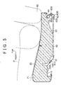
- the cushion pad 20 is different from an ordinary cushion pad in that cut portions 20B extending in a direction from the rear side toward the front side are provided in right and left side portions in the cushion pad 20 (refer to FIG. 1 ). In a lower surface of the cushion pad 20, a cut portion 20A extending in the right-left direction is provided between front end portions of the cut portions 20B (refer to FIG 5 ).
- the cushion pad 20 includes a fixed portion 21 that is disposed on the upper surfaces of the cushion panel 14 and the side frames 11, 12 of the cushion frame 10 and is supported at a fixed position, and a movable portion 22 that is disposed on the S-shaped springs 42 of the support body 40, and is supported so as to be movable.
- the fixed portion 21 and the movable portion 22 are formed as the cushion pad 20, that is, the fixed portion 21 and the movable portion 22 are formed as one unit. However, since the cushion pad 20 is partially divided by the cut portion 20A and the cut portions 20B, the fixed portion 21 is stably fixed on the upper surfaces of the cushion panel 14 and the side frames 11, 12, and the movable portion 22 is fixed on the support body 40 such that the movable portion 22 is able to be swung in the right-left direction.
- buttocks of the seated occupant are indicated by the reference sign P.
- a seat back is indicated by the reference numeral 60
- a lower limb of the seated occupant is indicated by the reference sign P.
- the S-shaped springs 42 of the support body 40 are swung in the right-left direction together with the swinging piece 41 and the movable portion 22 of the cushion pad 20.
- the spring bracket 43 provided integrally with the rear end portions of the S-shaped springs 42 are also moved in the right-left direction along the sliding hole 43A, together with the swinging piece 41 and the S-shaped springs 42.
- the support body 40 can be swung without warping the S-shaped springs 42. Therefore, the support body 40 is smoothly swung.
- the sliding hole 43A with the arc shape is formed such that a center portion of the sliding hole 43A at a center position in the width of the support body 40 in the right-left direction is located at the lowest position. Therefore, the support body 40, which has been swung, receives a force for returning the support body 40 to the position at which the support body 40 is located before being swung, due to gravity received by the stepped bolt 43B via the support body 40. Accordingly, when the occupant is seated without swinging his or her upper body to the right and left,.the support body 40 is maintained at a neutral position at which the support body 40 is not swung.
- FIG. 6 illustrates a state in which the occupant P seated on the seat tilts his or her upper body to the right side as indicated by an arrow T.
- the movable portion 22 of the cushion pad 20 moves toward the upper left side together with the support body 40 as indicated by a shaded arrow.
- the left side of the buttocks of the occupant P moves upward so as to be away from the movable portion 22 (including the cushion cover 30).
- a contact pressure between the left side of the buttocks of the occupant P and the movable portion 22 decreases.
- the occupant P seated on the seat tilts his or her upper body toward the left side opposite to the right side toward which the occupant P tilts his or her upper body in FIG.
- the movable portion 22 moves toward the upper right side opposite to the side indicated by the shaded arrow, the right side of the buttocks of the occupant P moves upward so as to be away from the movable portion 22, and the contact pressure between the right side of the buttocks of the occupant P and the movable portion 22 decreases.
- the contact pressure between the buttocks of the occupant P and the movable portion 22 is changed, a massaging effect on the buttocks of the occupant P is obtained, and blood circulation in the buttocks is promoted.
- the movable portion 22 moves to the right and left in accordance with the movement of the upper body of the occupant P as described above, the occupant P can easily move his or her upper body as if the occupant used an exercise machine. Thus, the blood circulation in the body is promoted due to an exercise effect, and an increase in the degree of tiredness is suppressed.
- the movable portion 22 and the fixed portion 21 are covered with the cushion cover 30, and thus, the movable portion 22 is connected to the fixed portion 21 with the use of the cushion cover 30.
- the movable portion 22 when the movable portion 22 moves, the movable portion 22 can freely move without being pulled by the fixed portion 21 through the cushion cover 30, because the cushion cover 30 is more stretchable than an ordinary cushion cover.
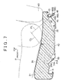
- a second embodiment of the invention will be described with reference to FIG. 7 to FIG. 9 .
- the feature of the second embodiment is that the rear portion of the support body 40 is rotated, whereas the rear portion of the support body 40 is linearly moved in the first embodiment.
- the other portions of the configuration in the second embodiment are the same as those in the first embodiment. Therefore, the same portions are denoted by the same reference numerals or signs, and the repeated description thereof will be omitted.
- arrows indicate the directions when the vehicle seat is provided in the vehicle.
- a fixed bracket 48 is fixed to the rear pipe 13 by welding.
- the fixed bracket 48 includes a portion extending along an upper portion to a front lower side of the rear pipe 13, and an extended portion that is extended and slightly tilted toward the rear side.
- a sliding hole 48A that is elongated in the right-left direction (extends in the right-left direction) is provided in the extended portion.
- the sliding hole 48A has an arc shape, and extends along a swinging trajectory of the support body 40.
- FIG. 7 shows a rotation center line CL for a swinging piece 45 that is similar to the swinging piece 41 in the first embodiment.
- FIG. 7 also shows that the fixed bracket 48 is disposed along a plane PL that is orthogonal to the rotation center line CL.
- a first spring bracket 46 is connected to the second spring bracket 47 by welding (refer to FIG. 7 and FIG 8 ).
- the first spring bracket 46 includes a tilted portion 46B that is tilted downward in the rearward direction so as to be parallel to the tilt (inclination) of the swinging piece 45.
- a weld nut 46A is fixed to the tilted portion 46B by welding.
- a stepped bolt 48B that extends through the sliding hole 48A of the fixed bracket 48 is fastened to the weld nut 46A.
- a bush 48C is disposed between the stepped bolt 48B and an edge portion around the sliding hole 48A to decrease friction resistance between the stepped bolt 48B and the edge portion around the sliding hole 48A.
- the swinging piece 45 is connected to right and left end portions of the second spring bracket 47 by respective connection pieces 52, and the S-shaped springs 42 are arranged between the connection pieces 52.
- the support body 40 is swung in the right-left direction, and the movable portion 22 of the cushion pad 20 is also swung, as in the first embodiment.
- the second spring bracket 47 is also guided by the sliding hole 48A of the fixed bracket 48 via the first spring bracket 46 and the stepped bolt 48B (in other words, the second spring bracket 47 is connected to the fixed bracket 48 via the first spring bracket 46 and the stepped bolt 48B). Therefore, the support body 40 is rotated about the rotation center of the stepped hinge pin 41A.
- the sides of the buttocks of the occupant alternately move upward to be away from the movable portion 22, and thus, the contact pressure between one side of the buttocks and the movable portion 22, and the contact pressure between the other side of the buttocks and the movable portion 22 alternately decrease, as in the first embodiment.
- the massaging effect on the buttocks of the occupant P is obtained, and the blood circulation in the buttocks is promoted. Accordingly, it is possible to suppress an increase in the degree of tiredness of the body of the occupant P.
- the occupant P can easily move his or her upper body as if the occupant P used an exercise machine, and therefore, the blood circulation in the body is promoted due to the exercise effect, and an increase in the degree of tiredness is suppressed.
- the femoral region of the occupant is supported on the fixed portion 21 of the cushion pad 20, and the occupant P can stably maintain the seated posture.
- a third embodiment of the invention will be described with reference to FIG 10 .
- the feature of the third embodiment is that the rear portion of the support body 40 is rotated, whereas the rear portion of the support body 40 is linearly moved in the first embodiment.
- the other feature of the third embodiment is that the rear portion of the support body 40 is supported at two points, whereas the rear portion of the support body 40 is supported with respect to the fixed bracket 44 at one point in the first embodiment.
- the other portions of the configuration in the third embodiment are the same as those in the first embodiment. The same portions are denoted by the same reference numerals or signs, and the repeated description thereof will be omitted.
- arrows indicate the directions when the vehicle seat is provided in the vehicle.
- a fixed bracket 49 (refer to FIG.
- a spring bracket 50 (refer to FIG. 10 ) is connected to a rear end portion of the support body 40 (refer to FIG. 1 ).
- a pair of weld nuts 49A is respectively fixed to right and left side portions in a portion of the fixed bracket 49, the portion being located behind the rear pipe 13, and extending downward.
- a sliding hole 50A with an arc shape which is similar to the sliding hole 48A (refer to FIG 9 ) of the fixed bracket 48 in the second embodiment, is provided in an upper-side portion of the spring bracket 50 with an L-shaped cross-section.
- a pair of stepped bolts 50B extends through the sliding hole 50A, and the stepped bolts 50B are fastened to the weld nuts 49A, respectively.
- a bush 50C is disposed between each stepped bolt 50B and an edge portion around the sliding hole 50A of the spring bracket 50, to decrease the friction resistance between the stepped bolt 50B and the edge portion around the sliding hole 50A.
- the width of the sliding hole 50A in the right-left direction needs to be set to be larger than the width of the sliding hole 48A in the right-left direction.
- the difference between the widths of the sliding hole 50A and the sliding hole 48A is caused due to the fact that when the support body 40 is swung, the pair of stepped bolts 50B slides in the sliding hole 50A, whereas the one stepped bolt 48B slides in the sliding hole 48A.
- the width of the sliding hole 50A in the right-left direction is set to be larger than the width of the sliding hole 48A in the right-left direction by a length equivalent to a distance between the pair of stepped bolts 50B.
- the front end portion of the support body 40 is rotated about the stepped hinge pin 41A serving as the rotation center, and the rear end portion of the support body 40 is swung (moved) along the arc shape of the sliding hole 50A. Accordingly, the movable portion 22 of the cushion pad 20 is also swung.
- the massaging effect on the buttocks of the occupant P is obtained, and the blood circulation in the buttocks of the occupant P is promoted. Accordingly, it is possible to suppress an increase in the degree of tiredness of the body of the occupant P.
- the occupant P can easily move his or her upper body as if the occupant P used an exercise machine, and therefore, the blood circulation of the body is promoted due to the exercise effect, and an increase in the degree of tiredness is suppressed.
- the femoral region of the occupant is supported on the fixed portion 21 of the cushion pad 20, and therefore, the occupant can stably maintain the seated posture.
- the spring bracket 50 connected to the rear end portion of the support body 40 is supported by the pair of stepped bolts 50B. Accordingly, the support body 40 is supported at three points including a support point at which the front end portion of the support body 40 is supported by the stepped hinge pin 41A.
- the occupant can be stably supported, as compared to the configuration in each of the first and second embodiments, in which the support body 40 is supported at two points.
- the upper body is stably supported without being swung to the right and left.
- the fixed portion 21 and the movable portion 22 of the cushion pad 20 are formed as one unit.
- the fixed portion 21 and the movable portion 22 may be formed separately, that is, the fixed portion 21 and the movable portion 22 may be formed as separate bodies.
- the fixed portion 21 and the movable portion 22 are formed by respectively providing the cut portions, which extend from the rear side toward the front side, in the right and left side portions of the cushion pad 20, and surfaces defining the cut portions are vertical surfaces.
- the surfaces defining the cut portions may be tilted surfaces that are tilted upward in a direction toward the right side or in a direction toward the left side, and the movable portion 22 may be provided over the entire width of the cushion pad 20 in the right-left direction.
- the movable portion 22 and the fixed portion 21 are arranged in a top-bottom direction in each of the right and left side portions of the cushion pad 20. Therefore, when a sitting pressure is applied from an occupant, the fixed portion 21 and the movable portion 22 may directly contact each other.
- each of the sliding hole 43A of the spring bracket 43, the sliding hole 48A of the fixed bracket 48, and the sliding hole 50A of the spring bracket 50 has an arc shape.
- each of the sliding hole 43A, the sliding hole 48A, and the sliding hole 50A may have a straight line shape extending in the right-left direction.
- the support body 40 needs to be deformed so as to be twisted in the right-left direction, because the support body 40 is rotated about the front end side thereof.
- the support body 40 includes the S-shaped springs 42.
- the support body 40 may be formed by a plate member, or a stretchable cloth.
- the invention is applied to the seat cushion.
- the invention may be applied to a seat back.
- the invention is applied to the vehicle seat.
- the invention may be applied to other conveyance seats, such as seats in an airplane, a ship, and a train.
Landscapes
- Engineering & Computer Science (AREA)
- Aviation & Aerospace Engineering (AREA)
- Transportation (AREA)
- Mechanical Engineering (AREA)
- Seats For Vehicles (AREA)
- Chair Legs, Seat Parts, And Backrests (AREA)
Abstract

Description
- The invention relates to a conveyance seat including a seat frame serving as a frame that supports a load of a seated occupant, and a seat pad that is disposed on the seat frame, and flexibly receives the load of the seated occupant.
- When an occupant is seated in the same posture on a conveyance seat for a long time, the degree of tiredness of the occupant increases. Thus, Japanese Patent No.
4095583 - However, in the seat described in Japanese Patent No.
4095583 - In view of the above, the invention provides a conveyance seat that holds the body of an occupant and allows the occupant to partially move his or her body easily so that the seated posture of the occupant is stably maintained and blood circulation in the body is promoted to suppress an increase in the degree of tiredness.
- An aspect of the invention relates to a conveyance seat including: a seat frame serving as a frame that supports a load of a seated occupant; and a seat pad that is disposed on the seat frame, and flexibly receives the load of the seated occupant. The conveyance seat includes a support body disposed based on a center portion of a distribution of a sitting pressure applied by the seated occupant to.the seat pad. In the conveyance seat, the support body is supported with respect'to the seat frame such that a front end portion of the support body is rotatable in a right-left. direction about a straight line tilted upward in a direction from a front side toward a rear side, and a rear end portion of the support body is movable in the right-left direction; and the seat pad includes a fixed portion that is supported at a fixed position by the seat frame, and a movable portion that is supported by the support body such that the movable portion is movable. According to the above-described aspect, the fixed portion of the seat pad is supported, at the fixed position by the seat frame, and therefore, the seated posture of the occupant can be stably maintained by the fixed portion of the seat pad. Further, the movable portion of the seat pad is supported by the support body such that the movable portion is movable, and therefore, the occupant can easily swing his or her body while remaining in the seated posture. Thus, the pelvis is turned about a portion near the lumbar spine, and a sitting pressure is changed. Accordingly, blood circulation in the body is promoted to suppress an ingrease in the degree of tiredness.
- In the above-described aspect, the support body may include a spring body that is stretched and contracted along a support plane of the support body. In this configuration, since the support body includes the spring body, the support body can be used also as a spring body required in the seat frame. Further, since the support body includes the spring body, when a phase deviation occurs between the rotation angle of the front end portion of the support body and the moved position of the rear end portion of the support body, or when the front end portion is rotated and the rear end portion is linearly moved, the spring body can absorb the deviation.
- In the above-described aspect, a cut portion that allows the movable portion to move in accordance with movement of the support body may be provided at a border portion between the fixed portion and the movable portion of the seat pad. In this configuration, when the movable portion of the seat pad moves relative to the fixed portion of the seat pad, the fixed portion and the movable portion are not likely to influence each other. Therefore, the fixed portion can be stabilized at the fixed position more easily, and the movable portion can be moved together with the support body more easily. Accordingly, it is possible to enhance the effect of suppressing an increase in the degree of tiredness by promoting the blood circulation in the body while stably maintaining the seated posture of the occupant.
- Features, advantages, and technical and industrial significance of exemplary embodiments of the invention will be described below with reference to the accompanying drawings, in which like numerals denote like elements, and wherein:
-
FIG. 1 is an exploded perspective view illustrating a first embodiment of the invention; -
FIG. 2 is a partially enlarged perspective view illustrating the first embodiment of the invention; -
FIG. 3 is a partially enlarged exploded perspective view illustrating the first embodiment of the invention; -
FIG. 4 is a vertical sectional view in a width direction illustrating the first embodiment of the invention; -
FIG. 5 is a vertical sectional view in a front-rear direction illustrating the first embodiment of the invention; -
FIG. 6 is an explanatory view illustrating effects obtained in the first embodiment; -
FIG. 7 is a vertical sectional view in the front-rear direction illustrating a second embodiment of the invention; -
FIG. 8 is a perspective view illustrating a support body in the second embodiment; -
FIG. 9 is a front view illustrating a fixed bracket in the second embodiment; and -
FIG. 10 is a partially enlarged perspective view illustrating a third embodiment of the invention. - A first embodiment of the invention will be described with reference to
FIG. 1 to FIG. 6 : In the first embodiment, the invention is applied to a seat cushion of a front seat of a vehicle. In each drawing, arrows indicate directions when the seat is provided in the vehicle. The seat cushion is formed by disposing a cushion pad 20 (that may be regarded as a seat pad according to the invention) that flexibly receives a load of a seated occupant, on a cushion frame 10 (that may be regarded as a seat frame according to the invention) serving as a frame that supports the load of the seated occupant, and covering thecushion frame 10 and thecushion pad 20 with acushion cover 30, as in a known vehicle seat in related art. The basic structure of the seat cushion is the same as that of a known seat cushion in related art, and thus, detailed illustration and description of the basic structure of the seat cushion will be omitted. Thecushion frame 10 is formed by connecting acushion panel 14 and arear pipe 13 to right andleft side frames cushion panel 14 is welded to front ends of the right andleft side frames cushion panel 14, and upper end surfaces of theside frames cushion pad 20. - A tilted
portion 14A is provided in a portion in a rear side of thecushion panel 14, the portion being located between the right andleft side frames portion 14A is tilted downward in a rearward direction. Aswinging piece 41 with a substantially triangle shape is fitted to a center portion of thetilted portion 14A in a right-left direction with use of astepped hinge pin 41 A such that theswinging piece 41 is able to be swung (rotated) in the right-left direction. Thus, theswinging piece 41 is swung (rotated) in the right-left direction about a rotation axis that is perpendicular to thetilted portion 14A. That is, theswinging piece 41 is supported such that theswinging piece 41 is able to be swung (rotated) in the right-left direction about the straight line tilted upward in a direction from the front side toward the rear side. In other words, the swinging piece 41 (i.e., a front end portion of asupport body 40 to be described later) is tilted downward in the rearward direction. A portion of theswinging piece 41, which is located at a bottom side of the triangle shape, is bent to extend rearward in a horizontal direction. Portions of the plate surface of the bent portion are cut and raised to form fourspring receivers 41B. In theswinging piece 41, the fourspring receivers 41B are arranged in the right-left direction. Front ends of four S-shaped springs 42 (that may be regarded as a spring body according to the invention) engage with therespective spring receivers 41B. - A
fixed bracket 44 is fixed, by welding, to a center portion of therear pipe 13 in the right-left direction. An extended portion of thefixed bracket 44, which is disposed behind therear pipe 13, extends downward. Aspring bracket 43 is fitted to the extended portion of thefixed bracket 44, as clearly shown in each ofFIG. 3 andFIG. 5 . Thespring bracket 43 is longer than thefixed bracket 44 in the right-left direction. Thespring bracket 43 is a metal member that has an L-shaped cross-section. Asliding hole 43A is provided in an upper-side portion of thespring bracket 43 with the L-shaped cross-section, Thesliding hole 43A has an arc shape. Thesliding hole 43A is elongated in the right-left direction (i.e., extends in the right-left direction), and a center portion thereof is located at the lowest position. Thespring bracket 43 is connected to the fixedbracket 44 with the use of a steppedbolt 43B that extends through the slidinghole 43A, such that thespring bracket 43 is slidable in the right-left direction. In this case, the steppedbolt 43B is fastened to aweld nut 44A such that abush 43C is disposed between the steppedbolt 43B and an edge portion around the slidinghole 43A. Theweld nut 44A is fixed to the fixedbracket 44 by welding. Thebush 43C may be replaced by a bearing. Fourspring receivers 43D are provided in a lower-side front portion of thespring bracket 43 with the L-shaped cross-section. Thespring receivers 43D are similar to thespring receivers 41B of the swingingpiece 41. Thespring receivers 43D are oriented in a direction opposite to the direction in which thespring receivers 41B are oriented. The front ends of the four S-shapedsprings 42 engage with therespective spring receivers 41B, as described above, and rear ends of the four S-shapedsprings 42 engage with therespective spring receivers 43D. The swingingpiece 41 is connected to right and left end portions of thespring bracket 43 byrespective connection pieces 51, and the S-shapedsprings 42 are disposed between theconnection pieces 51. - The four S-shaped
springs 42 consist of two pairs of the S-shaped springs that are arranged in the right-left direction. Rear end portions of the S-shapedsprings 42 in each pair are bent toward each other. Abuffer member 42B made of resin is provided on engagement portions in the rear end portions of the S-shapedsprings 42 in each pair, the engagement portions engaging with thespring receivers 43D (refer toFIG. 2 ) so that the S-shapedsprings 42 do not directly contact therespective spring receivers 43D. This suppresses occurrence of squeak noise when an occupant is seated. Further, an .appropriate number ofconnection pieces 42C made of resin (twoconnection pieces 42C inFIG. 1 ) are provided to extend in the right-left direction across the four S-shapedsprings 42 arranged in the right-left direction so that the S-shapedsprings 42 are integrated with each other. Thebuffer members 42B and theconnection pieces 42C are formed integrally with the S-shapedsprings 42 by resin insert molding. The four S-shapedsprings 42, the swingingpiece 41,the.spring bracket 43, and theconnection pieces 51 form thesupport body 40. Thesupport body 40 is disposed based on a center portion of a distribution of a sitting pressure. - The
cushion pad 20 is different from an ordinary cushion pad in that cutportions 20B extending in a direction from the rear side toward the front side are provided in right and left side portions in the cushion pad 20 (refer toFIG. 1 ). In a lower surface of thecushion pad 20, acut portion 20A extending in the right-left direction is provided between front end portions of thecut portions 20B (refer toFIG 5 ). As a result, thecushion pad 20 includes a fixedportion 21 that is disposed on the upper surfaces of thecushion panel 14 and the side frames 11, 12 of thecushion frame 10 and is supported at a fixed position, and amovable portion 22 that is disposed on the S-shapedsprings 42 of thesupport body 40, and is supported so as to be movable. The fixedportion 21 and themovable portion 22 are formed as thecushion pad 20, that is, the fixedportion 21 and themovable portion 22 are formed as one unit. However, since thecushion pad 20 is partially divided by thecut portion 20A and thecut portions 20B, the fixedportion 21 is stably fixed on the upper surfaces of thecushion panel 14 and the side frames 11, 12, and themovable portion 22 is fixed on thesupport body 40 such that themovable portion 22 is able to be swung in the right-left direction. In each ofFIG. 4 andFIG. 6 , buttocks of the seated occupant are indicated by the reference sign P. InFIG. 5 , a seat back is indicated by thereference numeral 60, and a lower limb of the seated occupant is indicated by the reference sign P. - When the seated occupant is seated on the vehicle seat with the above-described configuration, a femoral region of the occupant is supported on the fixed
portion 21 of thecushion pad 20, and a most part of the buttocks of the occupant is supported on themovable portion 22 of thecushion pad 20. Therefore, the occupant is supported by the fixedportion 21, and the occupant can stably maintain the seated posture. Further, since themovable portion 22 is provided, the occupant can swing his or her body while remaining in the seated posture. Thus, the pelvis is turned about a portion near the lumbar spine, and the sitting pressure is changed. Accordingly, blood circulation in the body is promoted, and thus, an increase jn the degree of tiredness is suppressed. More specifically, when the occupant seated on the seat cushion swings his or her upper body to the right and left, the S-shapedsprings 42 of thesupport body 40 are swung in the right-left direction together with the swingingpiece 41 and themovable portion 22 of thecushion pad 20. At this time, thespring bracket 43 provided integrally with the rear end portions of the S-shapedsprings 42 are also moved in the right-left direction along the slidinghole 43A, together with the swingingpiece 41 and the S-shapedsprings 42. In this case, since the slidinghole 43A has the arc shape, thesupport body 40 can be swung without warping the S-shapedsprings 42. Therefore, thesupport body 40 is smoothly swung. Further, the slidinghole 43A with the arc shape is formed such that a center portion of the slidinghole 43A at a center position in the width of thesupport body 40 in the right-left direction is located at the lowest position. Therefore, thesupport body 40, which has been swung, receives a force for returning thesupport body 40 to the position at which thesupport body 40 is located before being swung, due to gravity received by the steppedbolt 43B via thesupport body 40. Accordingly, when the occupant is seated without swinging his or her upper body to the right and left,.thesupport body 40 is maintained at a neutral position at which thesupport body 40 is not swung. -
FIG. 6 illustrates a state in which the occupant P seated on the seat tilts his or her upper body to the right side as indicated by an arrow T. At this time, themovable portion 22 of thecushion pad 20 moves toward the upper left side together with thesupport body 40 as indicated by a shaded arrow. The left side of the buttocks of the occupant P moves upward so as to be away from the movable portion 22 (including the cushion cover 30). Thus, a contact pressure between the left side of the buttocks of the occupant P and themovable portion 22 decreases.. When the occupant P seated on the seat tilts his or her upper body toward the left side opposite to the right side toward which the occupant P tilts his or her upper body inFIG. 6 , themovable portion 22 moves toward the upper right side opposite to the side indicated by the shaded arrow, the right side of the buttocks of the occupant P moves upward so as to be away from themovable portion 22, and the contact pressure between the right side of the buttocks of the occupant P and themovable portion 22 decreases. Thus, when the occupant P seated on the seat swings his or her upper bod in the above-described manner, and thus the contact pressure between the buttocks of the occupant P and themovable portion 22 is changed, a massaging effect on the buttocks of the occupant P is obtained, and blood circulation in the buttocks is promoted. Accordingly, it is possible to suppress an increase in the degree of tiredness of the body of the occupant P. Further, since themovable portion 22 moves to the right and left in accordance with the movement of the upper body of the occupant P as described above, the occupant P can easily move his or her upper body as if the occupant used an exercise machine. Thus, the blood circulation in the body is promoted due to an exercise effect, and an increase in the degree of tiredness is suppressed. Themovable portion 22 and the fixedportion 21 are covered with thecushion cover 30, and thus, themovable portion 22 is connected to the fixedportion 21 with the use of thecushion cover 30. However, in this embodiment, when themovable portion 22 moves, themovable portion 22 can freely move without being pulled by the fixedportion 21 through thecushion cover 30, because thecushion cover 30 is more stretchable than an ordinary cushion cover. - A second embodiment of the invention will be described with reference to
FIG. 7 to FIG. 9 . The feature of the second embodiment is that the rear portion of thesupport body 40 is rotated, whereas the rear portion of thesupport body 40 is linearly moved in the first embodiment. The other portions of the configuration in the second embodiment are the same as those in the first embodiment. Therefore, the same portions are denoted by the same reference numerals or signs, and the repeated description thereof will be omitted. In each ofFIG. 7 to FIG. 9 , arrows indicate the directions when the vehicle seat is provided in the vehicle. - A fixed
bracket 48 is fixed to therear pipe 13 by welding. The fixedbracket 48 includes a portion extending along an upper portion to a front lower side of therear pipe 13, and an extended portion that is extended and slightly tilted toward the rear side. As clearly shown inFIG. 9 , in the extended portion, a slidinghole 48A that is elongated in the right-left direction (extends in the right-left direction) is provided. The slidinghole 48A has an arc shape, and extends along a swinging trajectory of thesupport body 40.FIG. 7 shows a rotation center line CL for a swingingpiece 45 that is similar to the swingingpiece 41 in the first embodiment.FIG. 7 also shows that the fixedbracket 48 is disposed along a plane PL that is orthogonal to the rotation center line CL. The rear ends of the S-shapedsprings 42 engage with asecond spring bracket 47 that corresponds to thespring bracket 43 in the first embodiment. Afirst spring bracket 46 is connected to thesecond spring bracket 47 by welding (refer toFIG. 7 andFIG 8 ). Thefirst spring bracket 46 includes a tiltedportion 46B that is tilted downward in the rearward direction so as to be parallel to the tilt (inclination) of the swingingpiece 45. In thefirst spring bracket 46, aweld nut 46A is fixed to the tiltedportion 46B by welding. A steppedbolt 48B that extends through the slidinghole 48A of the fixedbracket 48 is fastened to theweld nut 46A. Abush 48C is disposed between the steppedbolt 48B and an edge portion around the slidinghole 48A to decrease friction resistance between the steppedbolt 48B and the edge portion around the slidinghole 48A. The swingingpiece 45 is connected to right and left end portions of thesecond spring bracket 47 byrespective connection pieces 52, and the S-shapedsprings 42 are arranged between theconnection pieces 52. - In the vehicle seat with the above-described configuration, when the occupant seated on the seat cushion swings his or her upper body to the right and left, the
support body 40 is swung in the right-left direction, and themovable portion 22 of thecushion pad 20 is also swung, as in the first embodiment. At this time, thesecond spring bracket 47 is also guided by the slidinghole 48A of the fixedbracket 48 via thefirst spring bracket 46 and the steppedbolt 48B (in other words, thesecond spring bracket 47 is connected to the fixedbracket 48 via thefirst spring bracket 46 and the steppedbolt 48B). Therefore, thesupport body 40 is rotated about the rotation center of the steppedhinge pin 41A. - Accordingly, in the second embodiment, when the occupant seated on the seat swings his or her upper body to the right and left, the sides of the buttocks of the occupant alternately move upward to be away from the
movable portion 22, and thus, the contact pressure between one side of the buttocks and themovable portion 22, and the contact pressure between the other side of the buttocks and themovable portion 22 alternately decrease, as in the first embodiment. As a result, the massaging effect on the buttocks of the occupant P is obtained, and the blood circulation in the buttocks is promoted. Accordingly, it is possible to suppress an increase in the degree of tiredness of the body of the occupant P. Further, the occupant P can easily move his or her upper body as if the occupant P used an exercise machine, and therefore, the blood circulation in the body is promoted due to the exercise effect, and an increase in the degree of tiredness is suppressed. At this time, the femoral region of the occupant is supported on the fixedportion 21 of thecushion pad 20, and the occupant P can stably maintain the seated posture. - A third embodiment of the invention will be described with reference to
FIG 10 . The feature of the third embodiment is that the rear portion of thesupport body 40 is rotated, whereas the rear portion of thesupport body 40 is linearly moved in the first embodiment. The other feature of the third embodiment is that the rear portion of thesupport body 40 is supported at two points, whereas the rear portion of thesupport body 40 is supported with respect to the fixedbracket 44 at one point in the first embodiment. The other portions of the configuration in the third embodiment are the same as those in the first embodiment. The same portions are denoted by the same reference numerals or signs, and the repeated description thereof will be omitted. InFIG. 10 as well, arrows indicate the directions when the vehicle seat is provided in the vehicle. A fixed bracket 49 (refer toFIG. 10 ) is fixed to the rear pipe 13 (refer toFIG. 1 ) by welding, in the manner similar to the manner in which the fixedbracket 44 is fixed to therear pipe 13 in the first embodiment. A spring bracket 50 (refer toFIG. 10 ) is connected to a rear end portion of the support body 40 (refer toFIG. 1 ). A pair ofweld nuts 49A is respectively fixed to right and left side portions in a portion of the fixedbracket 49, the portion being located behind therear pipe 13, and extending downward. Further, a slidinghole 50A with an arc shape, which is similar to the slidinghole 48A (refer toFIG 9 ) of the fixedbracket 48 in the second embodiment, is provided in an upper-side portion of thespring bracket 50 with an L-shaped cross-section. A pair of steppedbolts 50B extends through the slidinghole 50A, and the steppedbolts 50B are fastened to theweld nuts 49A, respectively. At this time, abush 50C is disposed between each steppedbolt 50B and an edge portion around the slidinghole 50A of thespring bracket 50, to decrease the friction resistance between the steppedbolt 50B and the edge portion around the slidinghole 50A. Thus, when thesupport body 40 is rotated in the right-left direction, thespring bracket 50 is supported by the pair of steppedbolts 50B, and is swung in an arc along the slidinghole 50A, When the swing width of thesupport body 40 in the third embodiment is set to be equal to the swing width of thesupport body 40 in the second embodiment, the width of the slidinghole 50A in the right-left direction needs to be set to be larger than the width of the slidinghole 48A in the right-left direction. The difference between the widths of the slidinghole 50A and the slidinghole 48A is caused due to the fact that when thesupport body 40 is swung, the pair of steppedbolts 50B slides in the slidinghole 50A, whereas the one steppedbolt 48B slides in the slidinghole 48A. The width of the slidinghole 50A in the right-left direction is set to be larger than the width of the slidinghole 48A in the right-left direction by a length equivalent to a distance between the pair of steppedbolts 50B. - In the vehicle seat with the above-described configuration, as in the first embodiment, when the occupant seated on the seat cushion swings his or her upper body to the right and left, the front end portion of the
support body 40 is rotated about the steppedhinge pin 41A serving as the rotation center, and the rear end portion of thesupport body 40 is swung (moved) along the arc shape of the slidinghole 50A. Accordingly, themovable portion 22 of thecushion pad 20 is also swung. Thus, as in the first and second embodiments, the massaging effect on the buttocks of the occupant P is obtained, and the blood circulation in the buttocks of the occupant P is promoted. Accordingly, it is possible to suppress an increase in the degree of tiredness of the body of the occupant P. Further, the occupant P can easily move his or her upper body as if the occupant P used an exercise machine, and therefore, the blood circulation of the body is promoted due to the exercise effect, and an increase in the degree of tiredness is suppressed. At this time, the femoral region of the occupant is supported on the fixedportion 21 of thecushion pad 20, and therefore, the occupant can stably maintain the seated posture. In the third embodiment, thespring bracket 50 connected to the rear end portion of thesupport body 40 is supported by the pair of steppedbolts 50B. Accordingly, thesupport body 40 is supported at three points including a support point at which the front end portion of thesupport body 40 is supported by the steppedhinge pin 41A. Thus, the occupant can be stably supported, as compared to the configuration in each of the first and second embodiments, in which thesupport body 40 is supported at two points. As a result, when the occupant is seated without swinging his or her upper body to the right and left, the upper body is stably supported without being swung to the right and left. - Although the specific embodiments have been described, the invention is not limited to the appearances and the configurations in the embodiments, and various modifications, additions, and deletions may be made without departing from the scope of the invention. For example, in the above-described embodiments, the fixed
portion 21 and themovable portion 22 of thecushion pad 20 are formed as one unit. However, the fixedportion 21 and themovable portion 22 may be formed separately, that is, the fixedportion 21 and themovable portion 22 may be formed as separate bodies. In the above-described embodiments, the fixedportion 21 and themovable portion 22 are formed by respectively providing the cut portions, which extend from the rear side toward the front side, in the right and left side portions of thecushion pad 20, and surfaces defining the cut portions are vertical surfaces. However, the surfaces defining the cut portions may be tilted surfaces that are tilted upward in a direction toward the right side or in a direction toward the left side, and themovable portion 22 may be provided over the entire width of thecushion pad 20 in the right-left direction. In this case, themovable portion 22 and the fixedportion 21 are arranged in a top-bottom direction in each of the right and left side portions of thecushion pad 20. Therefore, when a sitting pressure is applied from an occupant, the fixedportion 21 and themovable portion 22 may directly contact each other. Thus, it is necessary to provide a sliding member between the fixedportion 21 and themovable portion 22 to prevent the direction contact between the fixedportion 21 and themovable portion 22, and to allow themovable portion 22 to move relative to the fixedportion 21. In the above-described embodiments, each of the slidinghole 43A of thespring bracket 43, the slidinghole 48A of the fixedbracket 48, and the slidinghole 50A of thespring bracket 50 has an arc shape. However, each of the slidinghole 43A, the slidinghole 48A, and the slidinghole 50A may have a straight line shape extending in the right-left direction. However, in this case, that is, in the case where the slidinghole support body 40 needs to be deformed so as to be twisted in the right-left direction, because thesupport body 40 is rotated about the front end side thereof. In the above-described embodiments, thesupport body 40 includes the S-shapedsprings 42. However, thesupport body 40 may be formed by a plate member, or a stretchable cloth. In the above-described embodiments, the invention is applied to the seat cushion. However, the invention may be applied to a seat back. In the above-described embodiments, the invention is applied to the vehicle seat. However, the invention may be applied to other conveyance seats, such as seats in an airplane, a ship, and a train.
Claims (5)
- A conveyance seat including: a seat frame (10) serving as a frame that supports a load of a seated occupant; and a seat pad (20) that.is disposed on the seat frame (10), and flexibly receives the load of the seated occupant, the conveyance seat characterized by comprising
a support body (40) disposed based one a center portion of a distribution of a sitting pressure applied by the seated occupant to the seat pad (20),
wherein:the support body (40) is supported with respect to the seat frame (10) such that a front end portion of the support body (40) is rotatable in a right-left direction about a straight line tilted upward in a direction from a front side toward a rear side, and a rear end portion of the support body (40) is movable in the right-left direction; andthe seat pad (20) includes a fixed portion (21) that is supported at a fixed position by the seat frame (10), and a movable portion (22) that is supported by the support body (40) such that the movable portion (22) is movable. - The conveyance seat according to claim 1, wherein the support body (40) includes a spring body (42) that is stretched and contracted along a support plane of the support body (40).
- The conveyance seat according to claim 1 or 2, wherein a cut portion that allows the movable portion (22) to move in accordance with movement of the support body (40) is provided at a border portion between the fixed portion (21) and the movable portion (22) of the seat pad (20).
- The conveyance seat according to any one of claims 1 to 3, wherein:the support body (40) includes a spring bracket, and a fixed bracket is fixed to the seat frame (10); anda sliding hole is provided in one of the spring bracket and the fixed bracket, and the spring bracket is connected to the fixed bracket such that the spring bracket is. movable in the right-left direction, with use of at least one bolt extending through the sliding hole.
- The conveyance seat according to claim 4, wherein the sliding hole has an arc shape, and extends in the right-left direction.
Applications Claiming Priority (1)
| Application Number | Priority Date | Filing Date | Title |
|---|---|---|---|
| JP2013217503A JP5805730B2 (en) | 2013-02-08 | 2013-10-18 | Vehicle seat |
Publications (2)
| Publication Number | Publication Date |
|---|---|
| EP2862746A1 true EP2862746A1 (en) | 2015-04-22 |
| EP2862746B1 EP2862746B1 (en) | 2018-05-02 |
Family
ID=51703078
Family Applications (1)
| Application Number | Title | Priority Date | Filing Date |
|---|---|---|---|
| EP14189152.3A Not-in-force EP2862746B1 (en) | 2013-10-18 | 2014-10-16 | Vehicle seat |
Country Status (2)
| Country | Link |
|---|---|
| EP (1) | EP2862746B1 (en) |
| CN (1) | CN104553896B (en) |
Cited By (2)
| Publication number | Priority date | Publication date | Assignee | Title |
|---|---|---|---|---|
| EP3811824A4 (en) * | 2018-11-21 | 2022-02-23 | Delta Kogyo Co., Ltd. | Seat |
| CN114940111A (en) * | 2022-06-28 | 2022-08-26 | 奇瑞汽车股份有限公司 | Self-adaptive adjustable seat side wing structure and seat assembly |
Families Citing this family (3)
| Publication number | Priority date | Publication date | Assignee | Title |
|---|---|---|---|---|
| EP3495200B1 (en) * | 2016-08-04 | 2022-09-07 | TS Tech Co., Ltd. | Seat |
| JP6925930B2 (en) | 2017-10-20 | 2021-08-25 | 株式会社タチエス | Vehicle seat |
| JP7107123B2 (en) * | 2018-09-19 | 2022-07-27 | トヨタ自動車株式会社 | vehicle seat |
Citations (7)
| Publication number | Priority date | Publication date | Assignee | Title |
|---|---|---|---|---|
| JP2005349956A (en) * | 2004-06-10 | 2005-12-22 | Nobuyoshi Kaneko | Cushion for driver |
| WO2007016625A1 (en) * | 2005-08-01 | 2007-02-08 | 89908, Inc., Dba Amp Research | Vehicle seat assembly |
| WO2013021497A1 (en) * | 2011-08-10 | 2013-02-14 | トヨタ自動車株式会社 | Vehicle seat apparatus |
| WO2013088826A1 (en) * | 2011-12-15 | 2013-06-20 | Udトラックス株式会社 | Seat cushion device |
| US20140225407A1 (en) * | 2013-02-08 | 2014-08-14 | Toyota Boshoku Kabushiki Kaisha | Vehicle seat |
| JP2014151766A (en) * | 2013-02-08 | 2014-08-25 | Toyota Boshoku Corp | Seat for vehicle |
| JP2014169067A (en) * | 2013-02-08 | 2014-09-18 | Toyota Boshoku Corp | Seat for vehicle |
Family Cites Families (3)
| Publication number | Priority date | Publication date | Assignee | Title |
|---|---|---|---|---|
| WO1996002221A1 (en) * | 1994-07-14 | 1996-02-01 | Jensen Robert J | Dynamic continuous passive motion chair |
| US7713220B2 (en) * | 2007-01-10 | 2010-05-11 | Samuel Chen | Multiple mode massage chair |
| CN102717727B (en) * | 2012-06-30 | 2014-12-03 | 天津博信汽车零部件有限公司 | Movable seat framework of seat cushion |
-
2014
- 2014-10-16 EP EP14189152.3A patent/EP2862746B1/en not_active Not-in-force
- 2014-10-17 CN CN201410554073.5A patent/CN104553896B/en not_active Expired - Fee Related
Patent Citations (8)
| Publication number | Priority date | Publication date | Assignee | Title |
|---|---|---|---|---|
| JP2005349956A (en) * | 2004-06-10 | 2005-12-22 | Nobuyoshi Kaneko | Cushion for driver |
| JP4095583B2 (en) | 2004-06-10 | 2008-06-04 | 信義 金子 | Driver cushion |
| WO2007016625A1 (en) * | 2005-08-01 | 2007-02-08 | 89908, Inc., Dba Amp Research | Vehicle seat assembly |
| WO2013021497A1 (en) * | 2011-08-10 | 2013-02-14 | トヨタ自動車株式会社 | Vehicle seat apparatus |
| WO2013088826A1 (en) * | 2011-12-15 | 2013-06-20 | Udトラックス株式会社 | Seat cushion device |
| US20140225407A1 (en) * | 2013-02-08 | 2014-08-14 | Toyota Boshoku Kabushiki Kaisha | Vehicle seat |
| JP2014151766A (en) * | 2013-02-08 | 2014-08-25 | Toyota Boshoku Corp | Seat for vehicle |
| JP2014169067A (en) * | 2013-02-08 | 2014-09-18 | Toyota Boshoku Corp | Seat for vehicle |
Cited By (3)
| Publication number | Priority date | Publication date | Assignee | Title |
|---|---|---|---|---|
| EP3811824A4 (en) * | 2018-11-21 | 2022-02-23 | Delta Kogyo Co., Ltd. | Seat |
| US11299076B2 (en) | 2018-11-21 | 2022-04-12 | Delta Kogyo Co., Ltd. | Seat |
| CN114940111A (en) * | 2022-06-28 | 2022-08-26 | 奇瑞汽车股份有限公司 | Self-adaptive adjustable seat side wing structure and seat assembly |
Also Published As
| Publication number | Publication date |
|---|---|
| CN104553896A (en) | 2015-04-29 |
| CN104553896B (en) | 2017-10-13 |
| EP2862746B1 (en) | 2018-05-02 |
Similar Documents
| Publication | Publication Date | Title |
|---|---|---|
| US9550440B2 (en) | Conveyance seat | |
| EP2862746B1 (en) | Vehicle seat | |
| US9872567B2 (en) | Chair with positioning member | |
| US20140225407A1 (en) | Vehicle seat | |
| JP6097823B2 (en) | Vehicle seat with lumbar support | |
| US9963055B2 (en) | Leg rest apparatus for vehicle seat | |
| JP2018199363A (en) | Vehicular seat | |
| WO2014033964A1 (en) | Vehicle seat, and seat frame for vehicle seat | |
| JP6237503B2 (en) | Vehicle seat | |
| JP2014151766A (en) | Seat for vehicle | |
| JP3172695U (en) | Adjustable back pad | |
| JP2006239079A (en) | Chair | |
| CN109476247B (en) | Vehicle seat | |
| JP6000871B2 (en) | Vehicle seat | |
| WO2013105559A1 (en) | Vehicle seat | |
| KR20130007125U (en) | Chair | |
| JP2018176774A (en) | Seat cushion | |
| JP6013285B2 (en) | Seat back structure | |
| JP6401355B2 (en) | Seat frame for vehicle seat | |
| JP6841093B2 (en) | Vehicle seat | |
| JP2016185809A (en) | Seat frame of vehicle seat | |
| JP6440022B2 (en) | Vehicle seat structure | |
| JP2016199147A (en) | Vehicle seat | |
| JP2017105400A (en) | Seat structure for vehicle | |
| KR20130044894A (en) | Seat back structure of seat for automobile |
Legal Events
| Date | Code | Title | Description |
|---|---|---|---|
| PUAI | Public reference made under article 153(3) epc to a published international application that has entered the european phase |
Free format text: ORIGINAL CODE: 0009012 |
|
| 17P | Request for examination filed |
Effective date: 20141016 |
|
| AK | Designated contracting states |
Kind code of ref document: A1 Designated state(s): AL AT BE BG CH CY CZ DE DK EE ES FI FR GB GR HR HU IE IS IT LI LT LU LV MC MK MT NL NO PL PT RO RS SE SI SK SM TR |
|
| AX | Request for extension of the european patent |
Extension state: BA ME |
|
| 17Q | First examination report despatched |
Effective date: 20160210 |
|
| GRAP | Despatch of communication of intention to grant a patent |
Free format text: ORIGINAL CODE: EPIDOSNIGR1 |
|
| INTG | Intention to grant announced |
Effective date: 20171114 |
|
| GRAS | Grant fee paid |
Free format text: ORIGINAL CODE: EPIDOSNIGR3 |
|
| GRAA | (expected) grant |
Free format text: ORIGINAL CODE: 0009210 |
|
| RAP1 | Party data changed (applicant data changed or rights of an application transferred) |
Owner name: TOYOTA JIDOSHA KABUSHIKI KAISHA Owner name: TOYOTA BOSHOKU KABUSHIKI KAISHA |
|
| AK | Designated contracting states |
Kind code of ref document: B1 Designated state(s): AL AT BE BG CH CY CZ DE DK EE ES FI FR GB GR HR HU IE IS IT LI LT LU LV MC MK MT NL NO PL PT RO RS SE SI SK SM TR |
|
| REG | Reference to a national code |
Ref country code: GB Ref legal event code: FG4D |
|
| REG | Reference to a national code |
Ref country code: CH Ref legal event code: EP Ref country code: AT Ref legal event code: REF Ref document number: 994845 Country of ref document: AT Kind code of ref document: T Effective date: 20180515 |
|
| REG | Reference to a national code |
Ref country code: DE Ref legal event code: R096 Ref document number: 602014024774 Country of ref document: DE Ref country code: IE Ref legal event code: FG4D |
|
| REG | Reference to a national code |
Ref country code: NL Ref legal event code: MP Effective date: 20180502 |
|
| REG | Reference to a national code |
Ref country code: LT Ref legal event code: MG4D |
|
| PG25 | Lapsed in a contracting state [announced via postgrant information from national office to epo] |
Ref country code: ES Free format text: LAPSE BECAUSE OF FAILURE TO SUBMIT A TRANSLATION OF THE DESCRIPTION OR TO PAY THE FEE WITHIN THE PRESCRIBED TIME-LIMIT Effective date: 20180502 Ref country code: NO Free format text: LAPSE BECAUSE OF FAILURE TO SUBMIT A TRANSLATION OF THE DESCRIPTION OR TO PAY THE FEE WITHIN THE PRESCRIBED TIME-LIMIT Effective date: 20180802 Ref country code: BG Free format text: LAPSE BECAUSE OF FAILURE TO SUBMIT A TRANSLATION OF THE DESCRIPTION OR TO PAY THE FEE WITHIN THE PRESCRIBED TIME-LIMIT Effective date: 20180802 Ref country code: FI Free format text: LAPSE BECAUSE OF FAILURE TO SUBMIT A TRANSLATION OF THE DESCRIPTION OR TO PAY THE FEE WITHIN THE PRESCRIBED TIME-LIMIT Effective date: 20180502 Ref country code: LT Free format text: LAPSE BECAUSE OF FAILURE TO SUBMIT A TRANSLATION OF THE DESCRIPTION OR TO PAY THE FEE WITHIN THE PRESCRIBED TIME-LIMIT Effective date: 20180502 Ref country code: SE Free format text: LAPSE BECAUSE OF FAILURE TO SUBMIT A TRANSLATION OF THE DESCRIPTION OR TO PAY THE FEE WITHIN THE PRESCRIBED TIME-LIMIT Effective date: 20180502 |
|
| PG25 | Lapsed in a contracting state [announced via postgrant information from national office to epo] |
Ref country code: GR Free format text: LAPSE BECAUSE OF FAILURE TO SUBMIT A TRANSLATION OF THE DESCRIPTION OR TO PAY THE FEE WITHIN THE PRESCRIBED TIME-LIMIT Effective date: 20180803 Ref country code: HR Free format text: LAPSE BECAUSE OF FAILURE TO SUBMIT A TRANSLATION OF THE DESCRIPTION OR TO PAY THE FEE WITHIN THE PRESCRIBED TIME-LIMIT Effective date: 20180502 Ref country code: LV Free format text: LAPSE BECAUSE OF FAILURE TO SUBMIT A TRANSLATION OF THE DESCRIPTION OR TO PAY THE FEE WITHIN THE PRESCRIBED TIME-LIMIT Effective date: 20180502 Ref country code: RS Free format text: LAPSE BECAUSE OF FAILURE TO SUBMIT A TRANSLATION OF THE DESCRIPTION OR TO PAY THE FEE WITHIN THE PRESCRIBED TIME-LIMIT Effective date: 20180502 Ref country code: NL Free format text: LAPSE BECAUSE OF FAILURE TO SUBMIT A TRANSLATION OF THE DESCRIPTION OR TO PAY THE FEE WITHIN THE PRESCRIBED TIME-LIMIT Effective date: 20180502 |
|
| REG | Reference to a national code |
Ref country code: AT Ref legal event code: MK05 Ref document number: 994845 Country of ref document: AT Kind code of ref document: T Effective date: 20180502 |
|
| PG25 | Lapsed in a contracting state [announced via postgrant information from national office to epo] |
Ref country code: RO Free format text: LAPSE BECAUSE OF FAILURE TO SUBMIT A TRANSLATION OF THE DESCRIPTION OR TO PAY THE FEE WITHIN THE PRESCRIBED TIME-LIMIT Effective date: 20180502 Ref country code: CZ Free format text: LAPSE BECAUSE OF FAILURE TO SUBMIT A TRANSLATION OF THE DESCRIPTION OR TO PAY THE FEE WITHIN THE PRESCRIBED TIME-LIMIT Effective date: 20180502 Ref country code: SK Free format text: LAPSE BECAUSE OF FAILURE TO SUBMIT A TRANSLATION OF THE DESCRIPTION OR TO PAY THE FEE WITHIN THE PRESCRIBED TIME-LIMIT Effective date: 20180502 Ref country code: PL Free format text: LAPSE BECAUSE OF FAILURE TO SUBMIT A TRANSLATION OF THE DESCRIPTION OR TO PAY THE FEE WITHIN THE PRESCRIBED TIME-LIMIT Effective date: 20180502 Ref country code: DK Free format text: LAPSE BECAUSE OF FAILURE TO SUBMIT A TRANSLATION OF THE DESCRIPTION OR TO PAY THE FEE WITHIN THE PRESCRIBED TIME-LIMIT Effective date: 20180502 Ref country code: AT Free format text: LAPSE BECAUSE OF FAILURE TO SUBMIT A TRANSLATION OF THE DESCRIPTION OR TO PAY THE FEE WITHIN THE PRESCRIBED TIME-LIMIT Effective date: 20180502 Ref country code: EE Free format text: LAPSE BECAUSE OF FAILURE TO SUBMIT A TRANSLATION OF THE DESCRIPTION OR TO PAY THE FEE WITHIN THE PRESCRIBED TIME-LIMIT Effective date: 20180502 |
|
| REG | Reference to a national code |
Ref country code: CH Ref legal event code: PK Free format text: BERICHTIGUNGEN |
|
| REG | Reference to a national code |
Ref country code: DE Ref legal event code: R097 Ref document number: 602014024774 Country of ref document: DE |
|
| RIC2 | Information provided on ipc code assigned after grant |
Ipc: B60N 2/70 20060101ALI20150220BHEP Ipc: B60N 2/44 20060101ALI20150220BHEP Ipc: B60N 2/58 20060101AFI20150220BHEP Ipc: B60N 2/64 20060101ALI20150220BHEP Ipc: B60N 2/02 20060101ALI20150220BHEP Ipc: B60N 2/72 20060101ALI20150220BHEP |
|
| PG25 | Lapsed in a contracting state [announced via postgrant information from national office to epo] |
Ref country code: IT Free format text: LAPSE BECAUSE OF FAILURE TO SUBMIT A TRANSLATION OF THE DESCRIPTION OR TO PAY THE FEE WITHIN THE PRESCRIBED TIME-LIMIT Effective date: 20180502 Ref country code: SM Free format text: LAPSE BECAUSE OF FAILURE TO SUBMIT A TRANSLATION OF THE DESCRIPTION OR TO PAY THE FEE WITHIN THE PRESCRIBED TIME-LIMIT Effective date: 20180502 |
|
| PLBE | No opposition filed within time limit |
Free format text: ORIGINAL CODE: 0009261 |
|
| STAA | Information on the status of an ep patent application or granted ep patent |
Free format text: STATUS: NO OPPOSITION FILED WITHIN TIME LIMIT |
|
| 26N | No opposition filed |
Effective date: 20190205 |
|
| PG25 | Lapsed in a contracting state [announced via postgrant information from national office to epo] |
Ref country code: SI Free format text: LAPSE BECAUSE OF FAILURE TO SUBMIT A TRANSLATION OF THE DESCRIPTION OR TO PAY THE FEE WITHIN THE PRESCRIBED TIME-LIMIT Effective date: 20180502 |
|
| REG | Reference to a national code |
Ref country code: CH Ref legal event code: PL |
|
| GBPC | Gb: european patent ceased through non-payment of renewal fee |
Effective date: 20181016 |
|
| REG | Reference to a national code |
Ref country code: BE Ref legal event code: MM Effective date: 20181031 |
|
| PG25 | Lapsed in a contracting state [announced via postgrant information from national office to epo] |
Ref country code: LU Free format text: LAPSE BECAUSE OF NON-PAYMENT OF DUE FEES Effective date: 20181016 Ref country code: MC Free format text: LAPSE BECAUSE OF FAILURE TO SUBMIT A TRANSLATION OF THE DESCRIPTION OR TO PAY THE FEE WITHIN THE PRESCRIBED TIME-LIMIT Effective date: 20180502 |
|
| REG | Reference to a national code |
Ref country code: IE Ref legal event code: MM4A |
|
| PG25 | Lapsed in a contracting state [announced via postgrant information from national office to epo] |
Ref country code: CH Free format text: LAPSE BECAUSE OF NON-PAYMENT OF DUE FEES Effective date: 20181031 Ref country code: FR Free format text: LAPSE BECAUSE OF NON-PAYMENT OF DUE FEES Effective date: 20181031 Ref country code: LI Free format text: LAPSE BECAUSE OF NON-PAYMENT OF DUE FEES Effective date: 20181031 Ref country code: BE Free format text: LAPSE BECAUSE OF NON-PAYMENT OF DUE FEES Effective date: 20181031 |
|
| PG25 | Lapsed in a contracting state [announced via postgrant information from national office to epo] |
Ref country code: GB Free format text: LAPSE BECAUSE OF NON-PAYMENT OF DUE FEES Effective date: 20181016 Ref country code: IE Free format text: LAPSE BECAUSE OF NON-PAYMENT OF DUE FEES Effective date: 20181016 |
|
| PG25 | Lapsed in a contracting state [announced via postgrant information from national office to epo] |
Ref country code: AL Free format text: LAPSE BECAUSE OF FAILURE TO SUBMIT A TRANSLATION OF THE DESCRIPTION OR TO PAY THE FEE WITHIN THE PRESCRIBED TIME-LIMIT Effective date: 20180502 |
|
| PG25 | Lapsed in a contracting state [announced via postgrant information from national office to epo] |
Ref country code: MT Free format text: LAPSE BECAUSE OF NON-PAYMENT OF DUE FEES Effective date: 20181016 |
|
| PG25 | Lapsed in a contracting state [announced via postgrant information from national office to epo] |
Ref country code: TR Free format text: LAPSE BECAUSE OF FAILURE TO SUBMIT A TRANSLATION OF THE DESCRIPTION OR TO PAY THE FEE WITHIN THE PRESCRIBED TIME-LIMIT Effective date: 20180502 |
|
| PG25 | Lapsed in a contracting state [announced via postgrant information from national office to epo] |
Ref country code: PT Free format text: LAPSE BECAUSE OF FAILURE TO SUBMIT A TRANSLATION OF THE DESCRIPTION OR TO PAY THE FEE WITHIN THE PRESCRIBED TIME-LIMIT Effective date: 20180502 |
|
| PG25 | Lapsed in a contracting state [announced via postgrant information from national office to epo] |
Ref country code: HU Free format text: LAPSE BECAUSE OF FAILURE TO SUBMIT A TRANSLATION OF THE DESCRIPTION OR TO PAY THE FEE WITHIN THE PRESCRIBED TIME-LIMIT; INVALID AB INITIO Effective date: 20141016 Ref country code: MK Free format text: LAPSE BECAUSE OF NON-PAYMENT OF DUE FEES Effective date: 20180502 Ref country code: CY Free format text: LAPSE BECAUSE OF FAILURE TO SUBMIT A TRANSLATION OF THE DESCRIPTION OR TO PAY THE FEE WITHIN THE PRESCRIBED TIME-LIMIT Effective date: 20180502 |
|
| PG25 | Lapsed in a contracting state [announced via postgrant information from national office to epo] |
Ref country code: IS Free format text: LAPSE BECAUSE OF FAILURE TO SUBMIT A TRANSLATION OF THE DESCRIPTION OR TO PAY THE FEE WITHIN THE PRESCRIBED TIME-LIMIT Effective date: 20180902 |
|
| PGFP | Annual fee paid to national office [announced via postgrant information from national office to epo] |
Ref country code: DE Payment date: 20201006 Year of fee payment: 7 |
|
| REG | Reference to a national code |
Ref country code: DE Ref legal event code: R119 Ref document number: 602014024774 Country of ref document: DE |
|
| PG25 | Lapsed in a contracting state [announced via postgrant information from national office to epo] |
Ref country code: DE Free format text: LAPSE BECAUSE OF NON-PAYMENT OF DUE FEES Effective date: 20220503 |