EP2862479A1 - Headrest support structure - Google Patents
Headrest support structure Download PDFInfo
- Publication number
- EP2862479A1 EP2862479A1 EP20130812816 EP13812816A EP2862479A1 EP 2862479 A1 EP2862479 A1 EP 2862479A1 EP 20130812816 EP20130812816 EP 20130812816 EP 13812816 A EP13812816 A EP 13812816A EP 2862479 A1 EP2862479 A1 EP 2862479A1
- Authority
- EP
- European Patent Office
- Prior art keywords
- headrest
- support
- headrest support
- leaf spring
- support bracket
- Prior art date
- Legal status (The legal status is an assumption and is not a legal conclusion. Google has not performed a legal analysis and makes no representation as to the accuracy of the status listed.)
- Granted
Links
Images


Classifications
-
- B—PERFORMING OPERATIONS; TRANSPORTING
- B60—VEHICLES IN GENERAL
- B60N—SEATS SPECIALLY ADAPTED FOR VEHICLES; VEHICLE PASSENGER ACCOMMODATION NOT OTHERWISE PROVIDED FOR
- B60N2/00—Seats specially adapted for vehicles; Arrangement or mounting of seats in vehicles
- B60N2/80—Head-rests
- B60N2/806—Head-rests movable or adjustable
- B60N2/838—Tiltable
-
- B—PERFORMING OPERATIONS; TRANSPORTING
- B60—VEHICLES IN GENERAL
- B60N—SEATS SPECIALLY ADAPTED FOR VEHICLES; VEHICLE PASSENGER ACCOMMODATION NOT OTHERWISE PROVIDED FOR
- B60N2/00—Seats specially adapted for vehicles; Arrangement or mounting of seats in vehicles
- B60N2/80—Head-rests
-
- A—HUMAN NECESSITIES
- A47—FURNITURE; DOMESTIC ARTICLES OR APPLIANCES; COFFEE MILLS; SPICE MILLS; SUCTION CLEANERS IN GENERAL
- A47C—CHAIRS; SOFAS; BEDS
- A47C7/00—Parts, details, or accessories of chairs or stools
- A47C7/36—Support for the head or the back
- A47C7/38—Support for the head or the back for the head
-
- B—PERFORMING OPERATIONS; TRANSPORTING
- B60—VEHICLES IN GENERAL
- B60N—SEATS SPECIALLY ADAPTED FOR VEHICLES; VEHICLE PASSENGER ACCOMMODATION NOT OTHERWISE PROVIDED FOR
- B60N2/00—Seats specially adapted for vehicles; Arrangement or mounting of seats in vehicles
- B60N2/80—Head-rests
- B60N2/803—Head-rests fixed
-
- B—PERFORMING OPERATIONS; TRANSPORTING
- B60—VEHICLES IN GENERAL
- B60N—SEATS SPECIALLY ADAPTED FOR VEHICLES; VEHICLE PASSENGER ACCOMMODATION NOT OTHERWISE PROVIDED FOR
- B60N2/00—Seats specially adapted for vehicles; Arrangement or mounting of seats in vehicles
- B60N2/80—Head-rests
- B60N2/806—Head-rests movable or adjustable
- B60N2/809—Head-rests movable or adjustable vertically slidable
-
- B—PERFORMING OPERATIONS; TRANSPORTING
- B60—VEHICLES IN GENERAL
- B60N—SEATS SPECIALLY ADAPTED FOR VEHICLES; VEHICLE PASSENGER ACCOMMODATION NOT OTHERWISE PROVIDED FOR
- B60N2/00—Seats specially adapted for vehicles; Arrangement or mounting of seats in vehicles
- B60N2/80—Head-rests
- B60N2/897—Head-rests with sleeves located in the back-rest for guiding the rods of the head-rest
-
- B—PERFORMING OPERATIONS; TRANSPORTING
- B60—VEHICLES IN GENERAL
- B60N—SEATS SPECIALLY ADAPTED FOR VEHICLES; VEHICLE PASSENGER ACCOMMODATION NOT OTHERWISE PROVIDED FOR
- B60N2205/00—General mechanical or structural details
- B60N2205/20—Measures for elimination or compensation of play or backlash
Definitions
- the present invention relates to a headrest support structure for elastically supporting a headrest so as to make the headrest function as a dynamic damper.
- the headrest support structure described therein is configured as follows. Note that, in the following description, that side of the headrest on which a head of a person sitting on a seat is placed is assumed a front side of the headrest support structure, and its reverse direction is assumed a rear side of the headrest support structure.
- a support bracket 51 is fixed to a seatback frame 50 forming a frame structure of a seatback.
- the support bracket 51 is made of a metal plate bent generally in a U-shape.
- Through holes 52, 53 are formed in an upper part and a lower part of the support bracket 51, respectively.
- the through hole 52 formed in the upper part of the support bracket 51 is an elongated hole extending in a seat longitudinal direction.
- a resin headrest support 54 for supporting a headrest stay 56 (see FIG. 11 ) is inserted into the through holes 52, 53.
- a wire-shaped spring 55 made of metal is provided over a front part of the through hole 52 of the support bracket 51.
- the headrest support 54 is attached to the support bracket 51 in a state where the headrest support 54 receives a biasing force of the spring 55 toward the rear side.
- the headrest support 54 attached to the headrest stay 56 is disposed swingably relative to the support bracket 51 in a longitudinal direction with the through hole 53 as a fulcrum, along with flexion of the spring 55.
- the headrest is elastically supported so as to be displaceable in the longitudinal direction, so that the headrest functions as a dynamic damper for reducing vibration of the seat in the longitudinal direction.
- Patent Document 1 Japanese Examined Utility Model Application Publication No. 61-149552
- An object of the present invention is to enable a headrest support to be smoothly inserted into a support bracket in a headrest support structure for making a headrest function as a dynamic damper by elastically supporting, by a spring, the support bracket to be inserted into the support bracket.
- a headrest support structure including: a metal tubular support bracket configured to be provided in a seatback frame; a resin headrest support configured to support a headrest stay and inserted into the support bracket; and a spring disposed between the support bracket and the headrest support.
- the headrest support is elastically supported in a swingable manner relative to the support bracket so as to make a headrest function as a dynamic damper.
- the spring is a metal leaf spring provided integrally with the headrest support.
- the metal leaf spring is provided integrally with the headrest support, the headrest support is never caught on the spring during the insertion. Further, the spring is made of metal and a member making contact with the spring in a sliding manner during the insertion of the headrest support is the metal support bracket, so that an increase of friction due to bite or the like is suppressed. Accordingly, it is possible to smoothly insert the headrest support into the support bracket in the headrest support structure for making the headrest function as a dynamic damper.
- the headrest support structure further include a metal stopper provided in the headrest support and formed integrally with the leaf spring, and the stopper regulate swing of the headrest support relative to the support bracket by abutting with an inner peripheral surface of the support bracket.
- a metal stopper provided in the headrest support and formed integrally with the leaf spring, and the stopper regulate swing of the headrest support relative to the support bracket by abutting with an inner peripheral surface of the support bracket.
- the leaf spring of the headrest support structure be a cantilever spring having a fixed end in an end thereof in an insertion direction of the headrest support with respect to the support bracket, and having a free end in its reverse end. In such a configuration, such improper assembly is hardly caused that the leaf spring is placed outside the support bracket at the time of insertion of the headrest support.
- the headrest support of the headrest support structure have a stay hole configured such that the headrest stay is inserted therein, and have a tubular shape of which an end in an insertion direction of the headrest stay is closed; and that the fixed end of the leaf spring be embedded in the end thus closed. With such a configuration, rigidity of the headrest support is increased.
- the following describes a first embodiment of a headrest support structure in detail with reference to FIGS. 1 to 7 .
- two support brackets 11 are provided at an interval in an upper part of a seatback frame 10 forming a framework of a seatback.
- Each of the support brackets 11 is made of metal so as to have a squarely cylindrical section, and is fixed to the support bracket 11 by welding or brazing.
- a resin headrest support 12 is inserted into each of the support brackets 11.
- two headrest stays 14 extending downward from a headrest 13 are inserted into the headrest supports 12, respectively, and thus, the headrest 13 is supported by the seatback frame 10.
- a lower end part of the headrest support 12 is formed to be tapered. Further, a stay hole 20 into which the headrest stay 14 is inserted is formed in an upper end of the headrest support 12 along its central axis.
- a bead 24 is provided on a front side of a lower part of the headrest support 12.
- the bead 24 is made of the same resin as the headrest support 12. Note that the bead 24 may be formed integrally with the headrest support 12, or the bead 24 may be formed separately and fixed to the headrest support 12 later by adhesion.
- a bead 22 is provided on a rear side of an upper part of the headrest stay 14.
- the bead 22 is also made of the same resin as the headrest support 12.
- a metal leaf spring 23 is provided on a rear side of the lower part of the headrest stay 14.
- the leaf spring 23 is a cantilever spring having a fixed end in an upper end thereof, that is, an end thereof in the insertion direction of the headrest support 12 with respect to the support bracket 11, and having a free end in its reverse end.
- the headrest support 12 is formed in a tubular shape having a closed lower end. That is, an end thereof in the insertion direction with respect to the support bracket 11 is closed. A base portion of the leaf spring 23, namely, the fixed end thereof is embedded in the closed end.
- a gap between an outer peripheral surface of the headrest support 12 and an inner peripheral surface of the support bracket 11 in the upper part of the headrest support 12 is reduced by the bead 22. Further, a gap between the outer peripheral surface of the headrest support 12 and the inner peripheral surface of the support bracket 11 in the lower part of the headrest support 12 is shortened by the bead 24, so that the leaf spring 23 abuts with a rearward inner wall of the support bracket 11 in a state where the leaf spring 23 is bent by a given amount.
- Cylindrical pins project on bilateral side surfaces of the upper part of the headrest support 12, namely, surfaces parallel to a plane of paper of FIG. 3 .
- the pins are supported pivotably by an inner wall of the support bracket 11. It is preferable for the pins to be placed at about the same height as the bead 22.
- Such a headrest support 12 is supported swingably around the pins relative to the support bracket 11. On the occasion of swing of the headrest support 12 in a counterclockwise direction in FIG 4 , a reaction force is generated due to flexion of the leaf spring 23.
- a range of such swing of the headrest support 12 is from a position where the bead 24 provided on its front lower part abuts with a forward inner wall of the support bracket 11 to a position where a lower part (a stopper 25) of the leaf spring 23 on a rearward side surface of the headrest support 12 abuts with the rearward inner wall of the support bracket 11.
- the headrest support 12 into which the headrest stay 14 is inserted swings around the pins relative to the support bracket 11 in the counterclockwise direction in FIG. 4 .
- the leaf spring 23 is pressed against the rearward inner wall of the support bracket 11 so as to be bent, so that a resistance to the displacement of the headrest 13 is generated.
- FIG 5 a relationship between a displacement of the headrest 13 in the longitudinal direction and a load necessary for the displacement is shown in FIG 5 . That is, a region where support rigidity of the headrest 13 is small is set from an initial position with a displacement of 0, that is, from a position of the headrest 13 under no external force toward the front side. Note that, with respect to forward displacement of more than a given amount and rearward displacement from the initial position, the support rigidity of the headrest 13 becomes large. In view of this, in a seat employing the headrest support structure, small vibration of the headrest 13 relative to the seatback frame 10 is allowed, and the headrest 13 functions as a dynamic damper for reducing vibration of the seat. Note that high support rigidity is exhibited with respect to the rearward displacement of the headrest 13, and therefore, when a vehicle has a rear-end collision, for example, a head of an occupant can be surely received by the headrest 13.
- the headrest support 12 is never caught on the leaf spring 23 during the insertion, because the metal leaf spring 23 is provided integrally with the headrest support 12. Further, the leaf spring 23 is made of metal. Since a member making contact with the leaf spring 23 in a sliding manner during the insertion of the headrest support 12 is the metal support bracket 11, an increase of friction due to bite is suppressed. On that account, in such a headrest support structure, the insertion of the headrest support 12 can be performed smoothly.
- a base end portion of the leaf spring 23 is embedded in the middle of the lower end of the headrest support 12 in its thickness direction. In this case, it is possible to increase holding power of the leaf spring 23 to the headrest support 12.
- the base end portion of the leaf spring 23 is embedded in an outer surface, that is, a lower surface of the lower end of the headrest support 12.
- the base end portion of the leaf spring 23 is disposed on an inner surface, that is, a top surface of the lower end of the headrest support 12. In the case of the examples of FIG.
- a resin portion of the headrest support 12 is not divided into two by the leaf spring 23 in the thickness direction in an area where the base end portion of the leaf spring 23 is inserted. Accordingly, a minimum thickness Tmin (a minimum value of the thickness) of the resin material of the headrest support 12 can be made larger.
- the metal leaf spring 23 provided integrally with the headrest support 12 is used as a spring for elastically supporting the headrest support 12 in a swingable manner relative to the support bracket 11 so as to make the headrest 13 function as a dynamic damper.
- an increase of friction due to catching of the spring to the headrest support 12 or bite of the spring is restrained, thereby allowing the support bracket 11 to be smoothly inserted into the headrest support 12.
- the leaf spring 23 is made of metal having a thermal expansion coefficient largely smaller than that of resin, it is possible to restrain a change of a support characteristic and a damper characteristic of the headrest 13 due to thermal expansion of the leaf spring 23.
- the leaf spring 23 is a cantilever spring having a fixed end in the end thereof in the insertion direction of the headrest support 12 with respect to the support bracket 11, and having a free end in its reverse end. In view of this, such improper assembly is hardly caused that the leaf spring 23 is placed outside the support bracket 11 at the time of insertion of the headrest support 12.
- the headrest support 12 includes a stay hole 20 into which the headrest stay 14 is inserted, and is formed in a tubular shape in which the end thereof in the insertion direction of the headrest stay 14 is closed. Since the base portion of the leaf spring 23 is embedded in the closed end, the rigidity of the headrest support 12 is increased.
- the headrest support structure of the present embodiment is the same as the first embodiment except for a configuration of a headrest support.
- a constituent common in the first embodiment has the same reference sign as in the first embodiment, and a detailed description thereof is omitted.
- a headrest support 30 employed in the headrest support structure of the present embodiment includes a metal portion 32 constituting its lower end part, and a resin portion 31 constituting the other part.
- the metal portion 32 made of metal is integrated with the resin portion 31 made of resin by insert molding.
- Pins (not shown) serving as a center of swing of a headrest support 12 relative to a support bracket 11 are provided on bilateral side surfaces of an upper part of the resin portion 31.
- beads 22, 24 are provided on a rearward upper part and a forward lower part of the resin portion 31, respectively.
- the metal portion 32 is formed in a tubular shape having a closed bottom portion.
- a leaf spring 33 is formed integrally with a rearward side surface of the metal portion 32.
- the leaf spring 33 is a cantilever spring having a fixed end in its lower end and a free end in its upper end.
- such a headrest support 30 is disposed swingably relative to the support bracket 11 in a state where the headrest support 30 is elastically supported by the leaf spring 33. Swing of the headrest support 30 in a direction where a headrest 13 is displaced forward is allowed to a position where a rear side of a lower end of the metal portion 32 abuts with a rearward inner wall of the support bracket 11, as illustrated in FIG. 9(b) . That is, in the headrest support 30, the rear side of the lower end of the metal portion 32 serves as a stopper 34.
- the stopper 34 for regulating the swing of the headrest support 12 relative to the support bracket 11 by abutting with an inner peripheral surface of the support bracket 11 is provided in the headrest support 12, and the stopper 34 is formed integrally with the leaf spring 33.
- the stopper 34 since a part made of resin having a thermal expansion coefficient larger than metal is not provided between the stopper 34 and the leaf spring 33, it is possible to restrain the influence of a temperature change with respect to a damper characteristic and a support characteristic of the headrest 13, appropriately.
- the leaf spring 23 is integrally fixed to the headrest support 12 such that the base portion of the leaf spring 23 is embedded in the lower end part of the headrest support 12, but the base portion may be embedded in a side wall of the headrest support 12 so that the leaf spring 23 is integrally fixed thereto.
- a leaf spring 41 can be provided in the side wall of the headrest support 12 by insert molding.
- the leaf spring 23, 33, 41 configured as a cantilever spring has a fixed end in the end thereof in the insertion direction of the headrest support 12 with respect to the support bracket 11, and has a free end in its reverse end. If improper assembly of the leaf spring 23, 33, 41 at the time of insertion of the headrest support 12 is reduced sufficiently, the leaf spring 23, 33, 41 may be disposed so as to have a free end in the end thereof in the insertion direction of the headrest support 12 with respect to the support bracket 11, and a fixed end in its reverse end.
- the leaf spring 23, 33 is a cantilever spring, but may be a double-holding spring having fixed ends at both ends thereof.
- the bead 22, 24 is provided on the outer peripheral surface of the headrest support 12, 30, but the bead 22, 24 may be provided on the inner peripheral surface of the support bracket 11.
- the bead 22, 24 is made of resin, but the bead 22, 24 may be made of any material provided that the material has rigidity sufficiently higher than the leaf spring 23, 33, 41.
- the bead 22, 24 may be omitted.
- the pins are provided in the upper part of the headrest support 12, 30, and the leaf spring 23, 33, 41 is provided on the rear side of the lower part of the headrest support 12, 30.
- the positions of the pins and the leaf spring 23, 33, 41 may be replaced. That is, the pins may be provided in the lower part of the headrest support 12, 30, and the leaf spring 23, 33, 41 may be provided on the front side of the upper part thereof. Even in such a case, if the allowable displacement of the headrest support 12 in the area where the stopper 25, 34 is provided can be made sufficiently large, it is possible to sufficiently decrease the influence of machining error, improper assembly, and thermal expansion of each member with respect to a damper characteristic or a support characteristic of the headrest 13.
- the pins serving as the center of the swing of the headrest support 12, 30 are formed on the bilateral side surfaces of the headrest support 12.
- the pins may be formed on the inner peripheral surface of the support bracket 11.
- a plurality of leaf springs 23, 33, 41 may be provided in the headrest support 12, 30.
- the leaf spring 23, 33, 41 may be provided on each of the front side and the rear side of the headrest support 12, 30.
- a support characteristic of the headrest 13 becomes different from that illustrated in FIG. 5 .
- the fact remains that small vibration of the headrest 13 relative to the seatback frame 10 is allowed, so that it is possible to make the headrest 13 function as a dynamic damper.
- the headrest support 12, 30 is formed in a tubular shape having a closed lower end.
- the headrest support 12, 30 may be formed in a tubular shape in which both ends are opened.
- the headrest support structure is applied to both of two right and left headrest stays 14, but the headrest support structure may be applied to only either one of them. That is, either one of the headrest stays 14 may be supported by a headrest support structure configured so that the headrest support 12 is rigidly supported by the support bracket 11 without any spring. Even in this case, in one of them which is supported by the headrest support structure of the above embodiment, the headrest stay 14 is supported elastically, so that it is possible to make the headrest 13 function as a dynamic damper.
Abstract

Description
- The present invention relates to a headrest support structure for elastically supporting a headrest so as to make the headrest function as a dynamic damper.
- As the headrest support structure as described above, there has been conventionally known a structure as described in Patent Document 1. The headrest support structure described therein is configured as follows. Note that, in the following description, that side of the headrest on which a head of a person sitting on a seat is placed is assumed a front side of the headrest support structure, and its reverse direction is assumed a rear side of the headrest support structure.
- As illustrated in
FIG. 11 , asupport bracket 51 is fixed to aseatback frame 50 forming a frame structure of a seatback. Thesupport bracket 51 is made of a metal plate bent generally in a U-shape. Throughholes support bracket 51, respectively. Note that the throughhole 52 formed in the upper part of thesupport bracket 51 is an elongated hole extending in a seat longitudinal direction. Aresin headrest support 54 for supporting a headrest stay 56 (seeFIG. 11 ) is inserted into the throughholes shaped spring 55 made of metal is provided over a front part of thethrough hole 52 of thesupport bracket 51. Theheadrest support 54 is attached to thesupport bracket 51 in a state where theheadrest support 54 receives a biasing force of thespring 55 toward the rear side. - As illustrated in
FIG. 12 , in the headrest support structure, theheadrest support 54 attached to theheadrest stay 56 is disposed swingably relative to thesupport bracket 51 in a longitudinal direction with thethrough hole 53 as a fulcrum, along with flexion of thespring 55. On that account, in the support structure, the headrest is elastically supported so as to be displaceable in the longitudinal direction, so that the headrest functions as a dynamic damper for reducing vibration of the seat in the longitudinal direction. - Patent Document 1: Japanese Examined Utility Model Application Publication No.
61-149552 - However, in such a conventional support structure, on the occasion of inserting the
headrest support 54 into the throughholes support bracket 51, when a position or an orientation of a central axis thereof is misaligned, theheadrest support 54 may be caught on thespring 55. Further, during the insertion, themetal spring 55 digs into a surface of the headrest support 54 or scrapes off the surface, so that friction between thespring 55 and theheadrest support 54 may become large. This may result in that, on the occasion of assembling of theheadrest support 54, theheadrest support 54 cannot be inserted into thesupport bracket 51 smoothly. - An object of the present invention is to enable a headrest support to be smoothly inserted into a support bracket in a headrest support structure for making a headrest function as a dynamic damper by elastically supporting, by a spring, the support bracket to be inserted into the support bracket.
- In order to achieve the above object, one aspect provides a headrest support structure including: a metal tubular support bracket configured to be provided in a seatback frame; a resin headrest support configured to support a headrest stay and inserted into the support bracket; and a spring disposed between the support bracket and the headrest support. The headrest support is elastically supported in a swingable manner relative to the support bracket so as to make a headrest function as a dynamic damper. The spring is a metal leaf spring provided integrally with the headrest support.
- In the above configuration, since the metal leaf spring is provided integrally with the headrest support, the headrest support is never caught on the spring during the insertion. Further, the spring is made of metal and a member making contact with the spring in a sliding manner during the insertion of the headrest support is the metal support bracket, so that an increase of friction due to bite or the like is suppressed. Accordingly, it is possible to smoothly insert the headrest support into the support bracket in the headrest support structure for making the headrest function as a dynamic damper.
- It is preferable that the headrest support structure further include a metal stopper provided in the headrest support and formed integrally with the leaf spring, and the stopper regulate swing of the headrest support relative to the support bracket by abutting with an inner peripheral surface of the support bracket. In this case, since a part made of resin having a thermal expansion coefficient larger than that of metal is not provided between the stopper and the leaf spring, it is possible to restrain the influence of a temperature change with respect to a damper characteristic and a support characteristic of the headrest, appropriately.
- It is preferable that the leaf spring of the headrest support structure be a cantilever spring having a fixed end in an end thereof in an insertion direction of the headrest support with respect to the support bracket, and having a free end in its reverse end. In such a configuration, such improper assembly is hardly caused that the leaf spring is placed outside the support bracket at the time of insertion of the headrest support.
- It is preferable that the headrest support of the headrest support structure have a stay hole configured such that the headrest stay is inserted therein, and have a tubular shape of which an end in an insertion direction of the headrest stay is closed; and that the fixed end of the leaf spring be embedded in the end thus closed. With such a configuration, rigidity of the headrest support is increased.
-
- [
FIG. 1] FIG. 1 is an exploded perspective view of a headrest support structure according to a first embodiment. - [
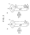
FIG. 2] FIG. 2(a) is a perspective view of a headrest support provided in the headrest support structure when viewed from a left front side; andFIG. 2(b) is a perspective view thereof when viewed from a right rear side. - [
FIG 3] FIG. 3 is a sectional side view of the headrest support and a support bracket. - [
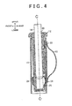
FIG. 4] FIG. 4 is a sectional side view of the headrest support and its peripheral area when a headrest is displaced forward. - [
FIG 5] FIG 5 is a graph showing a relationship between displacement of the headrest and a load required for the displacement of the headrest. - [
FIG. 6] FIG. 6 is a sectional side view of a tip end of the headrest support and its peripheral area when improper assembly occurs. - [
FIG 7] FIGS. 7(a) to 7(c) are sectional views each illustrating an insertion form of a leaf spring with respect to the headrest support. - [
FIG. 8] FIG. 8(a) is a perspective view of a headrest support provided in a headrest support structure according to a second embodiment when viewed from a left front side; andFIG. 8(b) is a perspective view thereof when viewed from a right rear side. - [
FIG. 9] FIG 9(a) is a sectional side view of a tip portion of the headrest support and its peripheral area when no external force is applied to a headrest; andFIG 9(b) is a sectional side view of the tip portion of the headrest support and its peripheral area when the headrest is displaced forward. - [
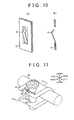
FIG. 10] FIG 10(a) is a perspective view illustrating another example of a spring that can be employed in the above embodiments; andFIG. 10(b) is a sectional side view of the another example. - [
FIG. 11] FIG. 11 is a view illustrating a perspective structure of a headrest support and its peripheral area of a conventional headrest support structure. - [
FIG. 12] FIG. 12 is a view illustrating a sectional structure of the headrest support and its peripheral area of the conventional headrest support structure, taken along a line 12-12 inFIG. 11 . - The following describes a first embodiment of a headrest support structure in detail with reference to
FIGS. 1 to 7 . - As illustrated in
FIG. 1 , twosupport brackets 11 are provided at an interval in an upper part of aseatback frame 10 forming a framework of a seatback. Each of thesupport brackets 11 is made of metal so as to have a squarely cylindrical section, and is fixed to thesupport bracket 11 by welding or brazing. Aresin headrest support 12 is inserted into each of thesupport brackets 11. Then, two headrest stays 14 extending downward from aheadrest 13 are inserted into the headrest supports 12, respectively, and thus, theheadrest 13 is supported by theseatback frame 10. - Note that, in the following description, that side of the
headrest 13 on which a head of a person sitting on a seat is placed is assumed a front side of a headrest support structure, and its reverse direction is assumed a rear side of the headrest support structure. Further, an insertion direction of theheadrest support 12 with respect to thesupport bracket 11 is assumed a lower side of the headrest support structure, and its reverse direction is assumed an upper side of the headrest support structure. - As illustrated in
FIG 2(a) , a lower end part of theheadrest support 12 is formed to be tapered. Further, astay hole 20 into which the headrest stay 14 is inserted is formed in an upper end of the headrest support 12 along its central axis. - A
bead 24 is provided on a front side of a lower part of theheadrest support 12. Thebead 24 is made of the same resin as the headrest support 12. Note that thebead 24 may be formed integrally with theheadrest support 12, or thebead 24 may be formed separately and fixed to theheadrest support 12 later by adhesion. - Further, as illustrated in
FIG. 2(b) , abead 22 is provided on a rear side of an upper part of the headrest stay 14. Thebead 22 is also made of the same resin as the headrest support 12. Further, ametal leaf spring 23 is provided on a rear side of the lower part of the headrest stay 14. Theleaf spring 23 is a cantilever spring having a fixed end in an upper end thereof, that is, an end thereof in the insertion direction of theheadrest support 12 with respect to thesupport bracket 11, and having a free end in its reverse end. - As illustrated in
FIG. 3 , theheadrest support 12 is formed in a tubular shape having a closed lower end. That is, an end thereof in the insertion direction with respect to thesupport bracket 11 is closed. A base portion of theleaf spring 23, namely, the fixed end thereof is embedded in the closed end. - Note that, as illustrated in
FIG. 3 , a gap between an outer peripheral surface of theheadrest support 12 and an inner peripheral surface of thesupport bracket 11 in the upper part of theheadrest support 12 is reduced by thebead 22. Further, a gap between the outer peripheral surface of theheadrest support 12 and the inner peripheral surface of thesupport bracket 11 in the lower part of theheadrest support 12 is shortened by thebead 24, so that theleaf spring 23 abuts with a rearward inner wall of thesupport bracket 11 in a state where theleaf spring 23 is bent by a given amount. Cylindrical pins (not shown) project on bilateral side surfaces of the upper part of theheadrest support 12, namely, surfaces parallel to a plane of paper ofFIG. 3 . The pins are supported pivotably by an inner wall of thesupport bracket 11. It is preferable for the pins to be placed at about the same height as thebead 22. - Such a
headrest support 12 is supported swingably around the pins relative to thesupport bracket 11. On the occasion of swing of theheadrest support 12 in a counterclockwise direction inFIG 4 , a reaction force is generated due to flexion of theleaf spring 23. A range of such swing of theheadrest support 12 is from a position where thebead 24 provided on its front lower part abuts with a forward inner wall of thesupport bracket 11 to a position where a lower part (a stopper 25) of theleaf spring 23 on a rearward side surface of theheadrest support 12 abuts with the rearward inner wall of thesupport bracket 11. - Next will be described an operation of such a headrest support structure.
- When the
headrest 13 is displaced forward, theheadrest support 12 into which theheadrest stay 14 is inserted swings around the pins relative to thesupport bracket 11 in the counterclockwise direction inFIG. 4 . On the occasion of the swing, theleaf spring 23 is pressed against the rearward inner wall of thesupport bracket 11 so as to be bent, so that a resistance to the displacement of theheadrest 13 is generated. - When a displacement of the
headrest 13 toward the front side reaches a given amount, thestopper 25 abuts with the rearward inner wall of thesupport bracket 11, so that further swing of theheadrest support 12 is regulated. Accordingly, further forward displacement of theheadrest 13 is performed by elastic deformation of theheadrest stay 14. - In the meantime, on the occasion of rearward displacement of the
headrest 13, since thebead 24 abuts with the forward inner wall of thesupport bracket 11, swing of theheadrest support 12 relative to thesupport bracket 11 is regulated from the first. Accordingly, the rearward displacement of theheadrest 13 is performed by elastic deformation of the headrest stay 14 from the beginning. - Accordingly, a relationship between a displacement of the
headrest 13 in the longitudinal direction and a load necessary for the displacement is shown inFIG 5 . That is, a region where support rigidity of theheadrest 13 is small is set from an initial position with a displacement of 0, that is, from a position of theheadrest 13 under no external force toward the front side. Note that, with respect to forward displacement of more than a given amount and rearward displacement from the initial position, the support rigidity of theheadrest 13 becomes large. In view of this, in a seat employing the headrest support structure, small vibration of theheadrest 13 relative to theseatback frame 10 is allowed, and theheadrest 13 functions as a dynamic damper for reducing vibration of the seat. Note that high support rigidity is exhibited with respect to the rearward displacement of theheadrest 13, and therefore, when a vehicle has a rear-end collision, for example, a head of an occupant can be surely received by theheadrest 13. - Note that, on the occasion of inserting the
headrest support 12 into thesupport bracket 11 at the time of assembly of the headrest support structure, theheadrest support 12 is never caught on theleaf spring 23 during the insertion, because themetal leaf spring 23 is provided integrally with theheadrest support 12. Further, theleaf spring 23 is made of metal. Since a member making contact with theleaf spring 23 in a sliding manner during the insertion of theheadrest support 12 is themetal support bracket 11, an increase of friction due to bite is suppressed. On that account, in such a headrest support structure, the insertion of theheadrest support 12 can be performed smoothly. - Note that, in a case where that end of the
leaf spring 23 in the insertion direction of theheadrest support 12 is a free end, when the central axis of theheadrest support 12 deviates or inclines from the central axis of thesupport bracket 11 at the time of the insertion, such improper assembly may be caused that theleaf spring 23 is placed outside thesupport bracket 11 as illustrated inFIG 6 . In that respect, in the headrest support structure of the present embodiment, since that end of theleaf spring 23 which is reverse to the insertion direction of theheadrest support 12 is a free end, such improper assembly does not occur. - Incidentally, even if a position of the
leaf spring 23 is replaced with a position of the pins, it is also possible to obtain a support characteristic of theheadrest 13 as illustrated inFIG. 5 . - Note that the following forms can be used as an insertion method of the
leaf spring 23 to theheadrest support 12. In an example ofFIG. 7(a) , a base end portion of theleaf spring 23 is embedded in the middle of the lower end of theheadrest support 12 in its thickness direction. In this case, it is possible to increase holding power of theleaf spring 23 to theheadrest support 12. In an example ofFIG. 7(b) , the base end portion of theleaf spring 23 is embedded in an outer surface, that is, a lower surface of the lower end of theheadrest support 12. Further, in an example ofFIG. 7(c) , the base end portion of theleaf spring 23 is disposed on an inner surface, that is, a top surface of the lower end of theheadrest support 12. In the case of the examples ofFIG. 7(b) and FIG. 7(c) , a resin portion of theheadrest support 12 is not divided into two by theleaf spring 23 in the thickness direction in an area where the base end portion of theleaf spring 23 is inserted. Accordingly, a minimum thickness Tmin (a minimum value of the thickness) of the resin material of theheadrest support 12 can be made larger. - According to the headrest support structure of the present embodiment described above, it is possible to yield the following effects.
- (1) In the present embodiment, the
metal leaf spring 23 provided integrally with theheadrest support 12 is used as a spring for elastically supporting theheadrest support 12 in a swingable manner relative to thesupport bracket 11 so as to make theheadrest 13 function as a dynamic damper. On that account, an increase of friction due to catching of the spring to theheadrest support 12 or bite of the spring is restrained, thereby allowing thesupport bracket 11 to be smoothly inserted into theheadrest support 12. - (2) Since the
leaf spring 23 is made of metal having a thermal expansion coefficient largely smaller than that of resin, it is possible to restrain a change of a support characteristic and a damper characteristic of theheadrest 13 due to thermal expansion of theleaf spring 23. - (3) The pins serving as a center of the swing of the
headrest support 12 relative to thesupport bracket 11 are provided in the upper part of theheadrest support 12, and theleaf spring 23 is provided on the rear side of the lower part of theheadrest support 12. Such a configuration makes it hard for the center of the swing of theheadrest support 12 relative to thesupport bracket 11 to vibrate, so that vibration of theheadrest 13 is easily controlled. Accordingly, it is possible to more precisely set a damper characteristic of theheadrest 13. - (4) Since the pins and the
leaf spring 23 are placed as described above, it is possible to increase an allowable displacement of theheadrest support 12 in an area where thestopper 25 is provided, thereby making it possible to further decrease the influence of machining error, improper assembly, and thermal expansion of each member with respect to a damper characteristic and a support characteristic of theheadrest 13. - (5) The
leaf spring 23 is a cantilever spring having a fixed end in the end thereof in the insertion direction of theheadrest support 12 with respect to thesupport bracket 11, and having a free end in its reverse end. In view of this, such improper assembly is hardly caused that theleaf spring 23 is placed outside thesupport bracket 11 at the time of insertion of theheadrest support 12. - (6) The
headrest support 12 includes astay hole 20 into which theheadrest stay 14 is inserted, and is formed in a tubular shape in which the end thereof in the insertion direction of theheadrest stay 14 is closed. Since the base portion of theleaf spring 23 is embedded in the closed end, the rigidity of theheadrest support 12 is increased. - Next will be described a second embodiment of the headrest support structure in detail with reference to
FIGS. 8 and9 . Note that the headrest support structure of the present embodiment is the same as the first embodiment except for a configuration of a headrest support. In the present embodiment, a constituent common in the first embodiment has the same reference sign as in the first embodiment, and a detailed description thereof is omitted. - As illustrated in
FIG. 8(a) and FIG. 8(b) , aheadrest support 30 employed in the headrest support structure of the present embodiment includes ametal portion 32 constituting its lower end part, and aresin portion 31 constituting the other part. Themetal portion 32 made of metal is integrated with theresin portion 31 made of resin by insert molding. Pins (not shown) serving as a center of swing of aheadrest support 12 relative to asupport bracket 11 are provided on bilateral side surfaces of an upper part of theresin portion 31. Further,beads resin portion 31, respectively. - The
metal portion 32 is formed in a tubular shape having a closed bottom portion. Aleaf spring 33 is formed integrally with a rearward side surface of themetal portion 32. Theleaf spring 33 is a cantilever spring having a fixed end in its lower end and a free end in its upper end. - As illustrated in
FIG. 9(a) , such aheadrest support 30 is disposed swingably relative to thesupport bracket 11 in a state where theheadrest support 30 is elastically supported by theleaf spring 33. Swing of theheadrest support 30 in a direction where aheadrest 13 is displaced forward is allowed to a position where a rear side of a lower end of themetal portion 32 abuts with a rearward inner wall of thesupport bracket 11, as illustrated inFIG. 9(b) . That is, in theheadrest support 30, the rear side of the lower end of themetal portion 32 serves as astopper 34. - According to the headrest support structure of the present embodiment described above, it is possible to yield the same effects as the first embodiment. Moreover, according to the headrest support structure of the present embodiment, it is possible to further yield the following effect.
- (7) In the present embodiment, the
stopper 34 for regulating the swing of theheadrest support 12 relative to thesupport bracket 11 by abutting with an inner peripheral surface of thesupport bracket 11 is provided in theheadrest support 12, and thestopper 34 is formed integrally with theleaf spring 33. In such a configuration, since a part made of resin having a thermal expansion coefficient larger than metal is not provided between thestopper 34 and theleaf spring 33, it is possible to restrain the influence of a temperature change with respect to a damper characteristic and a support characteristic of theheadrest 13, appropriately. - Note that the above embodiments can be modified as follows.
- - In the first embodiment, the
leaf spring 23 is integrally fixed to theheadrest support 12 such that the base portion of theleaf spring 23 is embedded in the lower end part of theheadrest support 12, but the base portion may be embedded in a side wall of theheadrest support 12 so that theleaf spring 23 is integrally fixed thereto. For example, as illustrated inFIG. 10(a) and FIG. 10(b) , aleaf spring 41 can be provided in the side wall of theheadrest support 12 by insert molding. - - In the above embodiment, the
leaf spring headrest support 12 with respect to thesupport bracket 11, and has a free end in its reverse end. If improper assembly of theleaf spring headrest support 12 is reduced sufficiently, theleaf spring headrest support 12 with respect to thesupport bracket 11, and a fixed end in its reverse end. - - In the above embodiment, the
leaf spring - - In the above embodiment, the
bead headrest support bead support bracket 11. - - In the above embodiment, the
bead bead leaf spring - - If it is possible to keep reduction in vibration of the center of the swing of the
support bracket 11 and abutment of theleaf spring support bracket 11 without providing thebead bead - - In the above embodiment, the pins are provided in the upper part of the
headrest support leaf spring headrest support leaf spring headrest support leaf spring headrest support 12 in the area where thestopper headrest 13. - - In the above embodiment, the pins serving as the center of the swing of the
headrest support headrest support 12. The pins may be formed on the inner peripheral surface of thesupport bracket 11. - - A plurality of
leaf springs headrest support leaf spring headrest support headrest 13 becomes different from that illustrated inFIG. 5 . However, the fact remains that small vibration of theheadrest 13 relative to theseatback frame 10 is allowed, so that it is possible to make theheadrest 13 function as a dynamic damper. - - In the above embodiment, the
headrest support headrest support - - In the above embodiment, the headrest support structure is applied to both of two right and left headrest stays 14, but the headrest support structure may be applied to only either one of them. That is, either one of the headrest stays 14 may be supported by a headrest support structure configured so that the
headrest support 12 is rigidly supported by thesupport bracket 11 without any spring. Even in this case, in one of them which is supported by the headrest support structure of the above embodiment, theheadrest stay 14 is supported elastically, so that it is possible to make theheadrest 13 function as a dynamic damper.
Claims (4)
- A headrest support structure comprising:a metal tubular support bracket configured to be provided in a seatback frame;a resin headrest support configured to support a headrest stay and inserted into the support bracket; anda spring disposed between the support bracket and the headrest support, wherein:the headrest support is elastically supported in a swingable manner relative to the support bracket so as to make a headrest function as a dynamic damper; andthe spring is a metal leaf spring provided integrally with the headrest support.
- The headrest support structure according to claim 1, further comprising:a metal stopper provided in the headrest support and formed integrally with the leaf spring, wherein:the stopper regulates swing of the headrest support relative to the support bracket by abutting with an inner peripheral surface of the support bracket.
- The headrest support structure according to claim 1 or 2, wherein:the leaf spring includes a cantilever spring having a fixed end in an end thereof in an insertion direction of the headrest support with respect to the support bracket, and having a free end in its reverse end.
- The headrest support structure according to any one of claims 1 to 3, wherein:the headrest support has a stay hole configured such that the headrest stay is inserted therein, and has a tubular shape of which an end in an insertion direction of the headrest stay is closed; andthe fixed end of the leaf spring is embedded in the end thus closed.
Applications Claiming Priority (3)
| Application Number | Priority Date | Filing Date | Title |
|---|---|---|---|
| JP2012148721A JP2014008335A (en) | 2012-07-02 | 2012-07-02 | Headrest support structure |
| JP2012194313A JP5803854B2 (en) | 2012-09-04 | 2012-09-04 | Headrest support structure |
| PCT/JP2013/068020 WO2014007202A1 (en) | 2012-07-02 | 2013-07-01 | Headrest support structure |
Publications (3)
| Publication Number | Publication Date |
|---|---|
| EP2862479A1 true EP2862479A1 (en) | 2015-04-22 |
| EP2862479A4 EP2862479A4 (en) | 2015-06-03 |
| EP2862479B1 EP2862479B1 (en) | 2019-04-24 |
Family
ID=49881958
Family Applications (1)
| Application Number | Title | Priority Date | Filing Date |
|---|---|---|---|
| EP13812816.0A Not-in-force EP2862479B1 (en) | 2012-07-02 | 2013-07-01 | Headrest support structure |
Country Status (5)
| Country | Link |
|---|---|
| US (1) | US20150145308A1 (en) |
| EP (1) | EP2862479B1 (en) |
| KR (1) | KR101591728B1 (en) |
| CN (1) | CN104334053B (en) |
| WO (1) | WO2014007202A1 (en) |
Families Citing this family (5)
| Publication number | Priority date | Publication date | Assignee | Title |
|---|---|---|---|---|
| US10099590B2 (en) * | 2012-07-02 | 2018-10-16 | Toyota Jidosha Kabushiki Kaisha | Headrest support structure |
| JP5814310B2 (en) * | 2013-07-19 | 2015-11-17 | トヨタ自動車株式会社 | Headrest support structure |
| JP6196184B2 (en) | 2014-04-25 | 2017-09-13 | トヨタ紡織株式会社 | Vehicle seat headrest assembly structure |
| US11086216B2 (en) | 2015-02-09 | 2021-08-10 | Microsoft Technology Licensing, Llc | Generating electronic components |
| DE102016208608B4 (en) * | 2015-11-13 | 2022-02-03 | Adient Luxembourg Holding S.À R.L. | Sliding sleeve and headrest assembly |
Family Cites Families (16)
| Publication number | Priority date | Publication date | Assignee | Title |
|---|---|---|---|---|
| DE3437476C2 (en) * | 1984-10-12 | 1986-10-02 | Daimler-Benz Ag, 7000 Stuttgart | Guide for a support rod of a height-adjustable headrest |
| JPH068622B2 (en) | 1984-12-24 | 1994-02-02 | アイシン精機株式会社 | Blower for Stirling engine |
| US4854642A (en) * | 1988-01-15 | 1989-08-08 | Hoover Universal, Inc. | Head restraint guide assembly |
| FR2751926B1 (en) * | 1996-07-31 | 1998-10-02 | Faure Bertrand Equipements Sa | VEHICLE SEAT COMPRISING A HEADREST, AND HEADREST FOR A VEHICLE SEAT |
| DE19717942A1 (en) * | 1997-04-29 | 1998-11-05 | Butz Peter Verwaltung | Headrests for vehicle seats |
| JP3513646B2 (en) * | 1998-09-29 | 2004-03-31 | 株式会社パイオラックス | Headrest support structure |
| DE10151360B4 (en) * | 2001-10-22 | 2007-10-18 | Ros Gmbh & Co. Kg | Device for receiving headrest straps |
| FR2849813B1 (en) * | 2003-01-15 | 2005-03-25 | Faurecia Sieges Automobile | HEADREST DEVICE FOR VEHICLE SEAT AND VEHICLE SEAT COMPRISING SUCH A DEVICE |
| JP4144514B2 (en) * | 2003-11-21 | 2008-09-03 | トヨタ自動車株式会社 | Headrest support structure |
| JP4854200B2 (en) * | 2005-01-21 | 2012-01-18 | 日本テクニカ株式会社 | Headrest support |
| DE102005019946B4 (en) * | 2005-04-29 | 2007-01-04 | Faurecia Autositze Gmbh & Co. Kg | Fastening device for the headrest of a vehicle seat |
| JP5226945B2 (en) * | 2006-10-16 | 2013-07-03 | 日本テクニカ株式会社 | Headrest support with stay and headrest support head rattle prevention mechanism |
| JP4287879B2 (en) * | 2006-12-27 | 2009-07-01 | 日本発條株式会社 | Active headrest headrest tilting device |
| EP2119603B1 (en) * | 2006-12-27 | 2012-02-15 | NHK Spring Co., Ltd. | Headrest tilting device for active headrest |
| CN103818284B (en) * | 2008-01-11 | 2016-03-23 | 提爱思科技股份有限公司 | Headrest support structure |
| JP5676281B2 (en) * | 2010-03-04 | 2015-02-25 | 難波プレス工業株式会社 | Vehicle seat with headrest |
-
2013
- 2013-07-01 EP EP13812816.0A patent/EP2862479B1/en not_active Not-in-force
- 2013-07-01 KR KR1020147033896A patent/KR101591728B1/en active IP Right Grant
- 2013-07-01 WO PCT/JP2013/068020 patent/WO2014007202A1/en active Application Filing
- 2013-07-01 CN CN201380029393.2A patent/CN104334053B/en not_active Expired - Fee Related
- 2013-07-01 US US14/405,184 patent/US20150145308A1/en not_active Abandoned
Also Published As
| Publication number | Publication date |
|---|---|
| CN104334053A (en) | 2015-02-04 |
| EP2862479A4 (en) | 2015-06-03 |
| EP2862479B1 (en) | 2019-04-24 |
| KR101591728B1 (en) | 2016-02-04 |
| WO2014007202A1 (en) | 2014-01-09 |
| KR20150005699A (en) | 2015-01-14 |
| CN104334053B (en) | 2018-07-20 |
| US20150145308A1 (en) | 2015-05-28 |
Similar Documents
| Publication | Publication Date | Title |
|---|---|---|
| EP2862479B1 (en) | Headrest support structure | |
| EP3022085B1 (en) | Headrest support structure | |
| US10099590B2 (en) | Headrest support structure | |
| US8876211B2 (en) | Seat assembly having a guide bushing | |
| US20120223563A1 (en) | Seat assembly having a cross member | |
| EP2995499B1 (en) | Headrest supporting structure | |
| JP6234761B2 (en) | Vehicle seat | |
| US20170341542A1 (en) | End stop with free play elimination to improve stiffness | |
| JP5803854B2 (en) | Headrest support structure | |
| JP5250054B2 (en) | Headrest structure | |
| JP4863362B2 (en) | Vehicle seat | |
| JP6030391B2 (en) | Chair | |
| JP2010202078A (en) | Vehicle seat | |
| JP5102981B2 (en) | Vehicle seat | |
| US10857921B1 (en) | Mat attachment structure of seatback and vehicle seat | |
| JP6976880B2 (en) | Mat mounting structure on the seat back and vehicle seat | |
| JP5099662B2 (en) | Vehicle seat | |
| JP5099663B2 (en) | Vehicle seat | |
| JP5433546B2 (en) | Headrest support structure | |
| JP2012011815A (en) | Vehicle seat |
Legal Events
| Date | Code | Title | Description |
|---|---|---|---|
| PUAI | Public reference made under article 153(3) epc to a published international application that has entered the european phase |
Free format text: ORIGINAL CODE: 0009012 |
|
| 17P | Request for examination filed |
Effective date: 20141202 |
|
| AK | Designated contracting states |
Kind code of ref document: A1 Designated state(s): AL AT BE BG CH CY CZ DE DK EE ES FI FR GB GR HR HU IE IS IT LI LT LU LV MC MK MT NL NO PL PT RO RS SE SI SK SM TR |
|
| AX | Request for extension of the european patent |
Extension state: BA ME |
|
| RA4 | Supplementary search report drawn up and despatched (corrected) |
Effective date: 20150506 |
|
| RIC1 | Information provided on ipc code assigned before grant |
Ipc: B60N 2/48 20060101ALI20150428BHEP Ipc: A47C 7/38 20060101AFI20150428BHEP |
|
| DAX | Request for extension of the european patent (deleted) | ||
| REG | Reference to a national code |
Ref country code: DE Ref legal event code: R079 Ref document number: 602013054398 Country of ref document: DE Free format text: PREVIOUS MAIN CLASS: A47C0007380000 Ipc: B60N0002900000 |
|
| RIC1 | Information provided on ipc code assigned before grant |
Ipc: B60N 2/809 20180101ALI20181004BHEP Ipc: B60N 2/838 20180101ALI20181004BHEP Ipc: B60N 2/90 20180101AFI20181004BHEP Ipc: B60N 2/80 20180101ALI20181004BHEP |
|
| GRAP | Despatch of communication of intention to grant a patent |
Free format text: ORIGINAL CODE: EPIDOSNIGR1 |
|
| STAA | Information on the status of an ep patent application or granted ep patent |
Free format text: STATUS: GRANT OF PATENT IS INTENDED |
|
| INTG | Intention to grant announced |
Effective date: 20181115 |
|
| RIC1 | Information provided on ipc code assigned before grant |
Ipc: B60N 2/809 20180101ALI20181004BHEP Ipc: B60N 2/90 20180101AFI20181004BHEP Ipc: B60N 2/838 20180101ALI20181004BHEP Ipc: B60N 2/80 20180101ALI20181004BHEP |
|
| GRAS | Grant fee paid |
Free format text: ORIGINAL CODE: EPIDOSNIGR3 |
|
| GRAA | (expected) grant |
Free format text: ORIGINAL CODE: 0009210 |
|
| STAA | Information on the status of an ep patent application or granted ep patent |
Free format text: STATUS: THE PATENT HAS BEEN GRANTED |
|
| AK | Designated contracting states |
Kind code of ref document: B1 Designated state(s): AL AT BE BG CH CY CZ DE DK EE ES FI FR GB GR HR HU IE IS IT LI LT LU LV MC MK MT NL NO PL PT RO RS SE SI SK SM TR |
|
| REG | Reference to a national code |
Ref country code: GB Ref legal event code: FG4D |
|
| REG | Reference to a national code |
Ref country code: CH Ref legal event code: EP |
|
| REG | Reference to a national code |
Ref country code: AT Ref legal event code: REF Ref document number: 1123738 Country of ref document: AT Kind code of ref document: T Effective date: 20190515 Ref country code: IE Ref legal event code: FG4D |
|
| REG | Reference to a national code |
Ref country code: DE Ref legal event code: R096 Ref document number: 602013054398 Country of ref document: DE |
|
| REG | Reference to a national code |
Ref country code: NL Ref legal event code: MP Effective date: 20190424 |
|
| PGFP | Annual fee paid to national office [announced via postgrant information from national office to epo] |
Ref country code: FR Payment date: 20190619 Year of fee payment: 7 |
|
| REG | Reference to a national code |
Ref country code: LT Ref legal event code: MG4D |
|
| PG25 | Lapsed in a contracting state [announced via postgrant information from national office to epo] |
Ref country code: NL Free format text: LAPSE BECAUSE OF FAILURE TO SUBMIT A TRANSLATION OF THE DESCRIPTION OR TO PAY THE FEE WITHIN THE PRESCRIBED TIME-LIMIT Effective date: 20190424 |
|
| PG25 | Lapsed in a contracting state [announced via postgrant information from national office to epo] |
Ref country code: AL Free format text: LAPSE BECAUSE OF FAILURE TO SUBMIT A TRANSLATION OF THE DESCRIPTION OR TO PAY THE FEE WITHIN THE PRESCRIBED TIME-LIMIT Effective date: 20190424 Ref country code: ES Free format text: LAPSE BECAUSE OF FAILURE TO SUBMIT A TRANSLATION OF THE DESCRIPTION OR TO PAY THE FEE WITHIN THE PRESCRIBED TIME-LIMIT Effective date: 20190424 Ref country code: PT Free format text: LAPSE BECAUSE OF FAILURE TO SUBMIT A TRANSLATION OF THE DESCRIPTION OR TO PAY THE FEE WITHIN THE PRESCRIBED TIME-LIMIT Effective date: 20190824 Ref country code: NO Free format text: LAPSE BECAUSE OF FAILURE TO SUBMIT A TRANSLATION OF THE DESCRIPTION OR TO PAY THE FEE WITHIN THE PRESCRIBED TIME-LIMIT Effective date: 20190724 Ref country code: LT Free format text: LAPSE BECAUSE OF FAILURE TO SUBMIT A TRANSLATION OF THE DESCRIPTION OR TO PAY THE FEE WITHIN THE PRESCRIBED TIME-LIMIT Effective date: 20190424 Ref country code: FI Free format text: LAPSE BECAUSE OF FAILURE TO SUBMIT A TRANSLATION OF THE DESCRIPTION OR TO PAY THE FEE WITHIN THE PRESCRIBED TIME-LIMIT Effective date: 20190424 Ref country code: SE Free format text: LAPSE BECAUSE OF FAILURE TO SUBMIT A TRANSLATION OF THE DESCRIPTION OR TO PAY THE FEE WITHIN THE PRESCRIBED TIME-LIMIT Effective date: 20190424 Ref country code: HR Free format text: LAPSE BECAUSE OF FAILURE TO SUBMIT A TRANSLATION OF THE DESCRIPTION OR TO PAY THE FEE WITHIN THE PRESCRIBED TIME-LIMIT Effective date: 20190424 |
|
| PGFP | Annual fee paid to national office [announced via postgrant information from national office to epo] |
Ref country code: DE Payment date: 20190618 Year of fee payment: 7 |
|
| PG25 | Lapsed in a contracting state [announced via postgrant information from national office to epo] |
Ref country code: RS Free format text: LAPSE BECAUSE OF FAILURE TO SUBMIT A TRANSLATION OF THE DESCRIPTION OR TO PAY THE FEE WITHIN THE PRESCRIBED TIME-LIMIT Effective date: 20190424 Ref country code: PL Free format text: LAPSE BECAUSE OF FAILURE TO SUBMIT A TRANSLATION OF THE DESCRIPTION OR TO PAY THE FEE WITHIN THE PRESCRIBED TIME-LIMIT Effective date: 20190424 Ref country code: LV Free format text: LAPSE BECAUSE OF FAILURE TO SUBMIT A TRANSLATION OF THE DESCRIPTION OR TO PAY THE FEE WITHIN THE PRESCRIBED TIME-LIMIT Effective date: 20190424 Ref country code: GR Free format text: LAPSE BECAUSE OF FAILURE TO SUBMIT A TRANSLATION OF THE DESCRIPTION OR TO PAY THE FEE WITHIN THE PRESCRIBED TIME-LIMIT Effective date: 20190725 Ref country code: BG Free format text: LAPSE BECAUSE OF FAILURE TO SUBMIT A TRANSLATION OF THE DESCRIPTION OR TO PAY THE FEE WITHIN THE PRESCRIBED TIME-LIMIT Effective date: 20190724 |
|
| REG | Reference to a national code |
Ref country code: AT Ref legal event code: MK05 Ref document number: 1123738 Country of ref document: AT Kind code of ref document: T Effective date: 20190424 |
|
| PG25 | Lapsed in a contracting state [announced via postgrant information from national office to epo] |
Ref country code: IS Free format text: LAPSE BECAUSE OF FAILURE TO SUBMIT A TRANSLATION OF THE DESCRIPTION OR TO PAY THE FEE WITHIN THE PRESCRIBED TIME-LIMIT Effective date: 20190824 |
|
| REG | Reference to a national code |
Ref country code: DE Ref legal event code: R097 Ref document number: 602013054398 Country of ref document: DE |
|
| PG25 | Lapsed in a contracting state [announced via postgrant information from national office to epo] |
Ref country code: DK Free format text: LAPSE BECAUSE OF FAILURE TO SUBMIT A TRANSLATION OF THE DESCRIPTION OR TO PAY THE FEE WITHIN THE PRESCRIBED TIME-LIMIT Effective date: 20190424 Ref country code: AT Free format text: LAPSE BECAUSE OF FAILURE TO SUBMIT A TRANSLATION OF THE DESCRIPTION OR TO PAY THE FEE WITHIN THE PRESCRIBED TIME-LIMIT Effective date: 20190424 Ref country code: EE Free format text: LAPSE BECAUSE OF FAILURE TO SUBMIT A TRANSLATION OF THE DESCRIPTION OR TO PAY THE FEE WITHIN THE PRESCRIBED TIME-LIMIT Effective date: 20190424 Ref country code: CZ Free format text: LAPSE BECAUSE OF FAILURE TO SUBMIT A TRANSLATION OF THE DESCRIPTION OR TO PAY THE FEE WITHIN THE PRESCRIBED TIME-LIMIT Effective date: 20190424 Ref country code: RO Free format text: LAPSE BECAUSE OF FAILURE TO SUBMIT A TRANSLATION OF THE DESCRIPTION OR TO PAY THE FEE WITHIN THE PRESCRIBED TIME-LIMIT Effective date: 20190424 Ref country code: SK Free format text: LAPSE BECAUSE OF FAILURE TO SUBMIT A TRANSLATION OF THE DESCRIPTION OR TO PAY THE FEE WITHIN THE PRESCRIBED TIME-LIMIT Effective date: 20190424 |
|
| PG25 | Lapsed in a contracting state [announced via postgrant information from national office to epo] |
Ref country code: MC Free format text: LAPSE BECAUSE OF FAILURE TO SUBMIT A TRANSLATION OF THE DESCRIPTION OR TO PAY THE FEE WITHIN THE PRESCRIBED TIME-LIMIT Effective date: 20190424 Ref country code: SM Free format text: LAPSE BECAUSE OF FAILURE TO SUBMIT A TRANSLATION OF THE DESCRIPTION OR TO PAY THE FEE WITHIN THE PRESCRIBED TIME-LIMIT Effective date: 20190424 Ref country code: IT Free format text: LAPSE BECAUSE OF FAILURE TO SUBMIT A TRANSLATION OF THE DESCRIPTION OR TO PAY THE FEE WITHIN THE PRESCRIBED TIME-LIMIT Effective date: 20190424 |
|
| PLBE | No opposition filed within time limit |
Free format text: ORIGINAL CODE: 0009261 |
|
| REG | Reference to a national code |
Ref country code: CH Ref legal event code: PL |
|
| STAA | Information on the status of an ep patent application or granted ep patent |
Free format text: STATUS: NO OPPOSITION FILED WITHIN TIME LIMIT |
|
| GBPC | Gb: european patent ceased through non-payment of renewal fee |
Effective date: 20190724 |
|
| PG25 | Lapsed in a contracting state [announced via postgrant information from national office to epo] |
Ref country code: TR Free format text: LAPSE BECAUSE OF FAILURE TO SUBMIT A TRANSLATION OF THE DESCRIPTION OR TO PAY THE FEE WITHIN THE PRESCRIBED TIME-LIMIT Effective date: 20190424 |
|
| 26N | No opposition filed |
Effective date: 20200127 |
|
| REG | Reference to a national code |
Ref country code: BE Ref legal event code: MM Effective date: 20190731 |
|
| PG25 | Lapsed in a contracting state [announced via postgrant information from national office to epo] |
Ref country code: GB Free format text: LAPSE BECAUSE OF NON-PAYMENT OF DUE FEES Effective date: 20190724 |
|
| PG25 | Lapsed in a contracting state [announced via postgrant information from national office to epo] |
Ref country code: SI Free format text: LAPSE BECAUSE OF FAILURE TO SUBMIT A TRANSLATION OF THE DESCRIPTION OR TO PAY THE FEE WITHIN THE PRESCRIBED TIME-LIMIT Effective date: 20190424 Ref country code: CH Free format text: LAPSE BECAUSE OF NON-PAYMENT OF DUE FEES Effective date: 20190731 Ref country code: LU Free format text: LAPSE BECAUSE OF NON-PAYMENT OF DUE FEES Effective date: 20190701 Ref country code: LI Free format text: LAPSE BECAUSE OF NON-PAYMENT OF DUE FEES Effective date: 20190731 Ref country code: BE Free format text: LAPSE BECAUSE OF NON-PAYMENT OF DUE FEES Effective date: 20190731 |
|
| PG25 | Lapsed in a contracting state [announced via postgrant information from national office to epo] |
Ref country code: IE Free format text: LAPSE BECAUSE OF NON-PAYMENT OF DUE FEES Effective date: 20190701 |
|
| REG | Reference to a national code |
Ref country code: DE Ref legal event code: R119 Ref document number: 602013054398 Country of ref document: DE |
|
| PG25 | Lapsed in a contracting state [announced via postgrant information from national office to epo] |
Ref country code: FR Free format text: LAPSE BECAUSE OF NON-PAYMENT OF DUE FEES Effective date: 20200731 |
|
| PG25 | Lapsed in a contracting state [announced via postgrant information from national office to epo] |
Ref country code: CY Free format text: LAPSE BECAUSE OF FAILURE TO SUBMIT A TRANSLATION OF THE DESCRIPTION OR TO PAY THE FEE WITHIN THE PRESCRIBED TIME-LIMIT Effective date: 20190424 Ref country code: DE Free format text: LAPSE BECAUSE OF NON-PAYMENT OF DUE FEES Effective date: 20210202 |
|
| PG25 | Lapsed in a contracting state [announced via postgrant information from national office to epo] |
Ref country code: MT Free format text: LAPSE BECAUSE OF FAILURE TO SUBMIT A TRANSLATION OF THE DESCRIPTION OR TO PAY THE FEE WITHIN THE PRESCRIBED TIME-LIMIT Effective date: 20190424 Ref country code: HU Free format text: LAPSE BECAUSE OF FAILURE TO SUBMIT A TRANSLATION OF THE DESCRIPTION OR TO PAY THE FEE WITHIN THE PRESCRIBED TIME-LIMIT; INVALID AB INITIO Effective date: 20130701 |
|
| PG25 | Lapsed in a contracting state [announced via postgrant information from national office to epo] |
Ref country code: MK Free format text: LAPSE BECAUSE OF FAILURE TO SUBMIT A TRANSLATION OF THE DESCRIPTION OR TO PAY THE FEE WITHIN THE PRESCRIBED TIME-LIMIT Effective date: 20190424 |