EP2862009B1 - Handwerkzeugvorrichtung - Google Patents
Handwerkzeugvorrichtung Download PDFInfo
- Publication number
- EP2862009B1 EP2862009B1 EP13717252.4A EP13717252A EP2862009B1 EP 2862009 B1 EP2862009 B1 EP 2862009B1 EP 13717252 A EP13717252 A EP 13717252A EP 2862009 B1 EP2862009 B1 EP 2862009B1
- Authority
- EP
- European Patent Office
- Prior art keywords
- locating
- antenna
- hand tool
- shielding means
- tool device
- Prior art date
- Legal status (The legal status is an assumption and is not a legal conclusion. Google has not performed a legal analysis and makes no representation as to the accuracy of the status listed.)
- Active
Links
Images


Classifications
-
- G—PHYSICS
- G01—MEASURING; TESTING
- G01V—GEOPHYSICS; GRAVITATIONAL MEASUREMENTS; DETECTING MASSES OR OBJECTS; TAGS
- G01V3/00—Electric or magnetic prospecting or detecting; Measuring magnetic field characteristics of the earth, e.g. declination, deviation
- G01V3/08—Electric or magnetic prospecting or detecting; Measuring magnetic field characteristics of the earth, e.g. declination, deviation operating with magnetic or electric fields produced or modified by objects or geological structures or by detecting devices
- G01V3/10—Electric or magnetic prospecting or detecting; Measuring magnetic field characteristics of the earth, e.g. declination, deviation operating with magnetic or electric fields produced or modified by objects or geological structures or by detecting devices using induction coils
-
- G—PHYSICS
- G01—MEASURING; TESTING
- G01R—MEASURING ELECTRIC VARIABLES; MEASURING MAGNETIC VARIABLES
- G01R1/00—Details of instruments or arrangements of the types included in groups G01R5/00 - G01R13/00 and G01R31/00
- G01R1/02—General constructional details
- G01R1/18—Screening arrangements against electric or magnetic fields, e.g. against earth's field
-
- G—PHYSICS
- G01—MEASURING; TESTING
- G01V—GEOPHYSICS; GRAVITATIONAL MEASUREMENTS; DETECTING MASSES OR OBJECTS; TAGS
- G01V3/00—Electric or magnetic prospecting or detecting; Measuring magnetic field characteristics of the earth, e.g. declination, deviation
- G01V3/15—Electric or magnetic prospecting or detecting; Measuring magnetic field characteristics of the earth, e.g. declination, deviation specially adapted for use during transport, e.g. by a person, vehicle or boat
Definitions
- a hand tool device with at least one locating device which is intended to locate a low-frequency alternating voltage in a workpiece and which has a first locating antenna and a second locating antenna, has already been proposed. Furthermore, hand tool devices with shielding means have already been proposed (see, for example, US 6,512,475 B1 , WO 2006/098751 A2 or US 2010/085234 A1 ).
- a radar device for locating objects enclosed in a medium comprising at least one radar sensor which generates a first, high-frequency detection signal for intervening in a medium to be examined, so that by measuring and evaluating the reflected detection signal of the radar sensor, information about an object enclosed in the medium can be obtained.
- the invention is based on a hand tool device according to claim 1 with at least one locating device which is intended to locate a low-frequency alternating voltage in a workpiece and which has a first locating antenna and a second locating antenna.
- the hand tool device has a shielding means for shielding a low-frequency locating signal, which is arranged between the first locating antenna and the second locating antenna.
- a "locating device” is to be understood in particular as a device that is provided to determine at least one item of location information about a measurement object arranged in a workpiece.
- the locating device preferably has a computing unit that is provided to determine at least one direction and/or a distance of the measurement object relative to the locating device.
- the locating device preferably has an output means via which the locating device outputs the location information to an operator.
- "provided” is to be understood as specifically programmed, designed and/or equipped.
- a "low-frequency alternating voltage” is to be understood in particular as a voltage with a Frequency less than 100 kHz, advantageously less than 10 kHz, particularly advantageously less than 1 kHz.
- the locating device is preferably designed to locate a mains voltage of 50 Hz and/or 60 Hz.
- the phrase "in a workpiece” is to be understood as meaning that the locating device is designed to locate the measurement object concealed within and/or behind the workpiece.
- the locating device is preferably designed to receive a locating signal that has penetrated the workpiece.
- “Locate” is to be understood, in particular, as determining at least one item of location information about a remotely and concealed measurement object.
- a "locating antenna” is to be understood as a means designed to convert an electrically, magnetically, and/or electromagnetically transmitted locating signal into a signal transmitted by an electrical conductor.
- a “shielding means” is understood, in particular, to mean a means intended to attenuate a low-frequency locating signal acting on the locating antenna from one direction by more than 6 dB, advantageously by more than 10 dB, particularly advantageously by more than 20 dB.
- the shielding means influences a main locating direction of the locating antennas.
- the shielding means is designed as an electrically conductive layer.
- the shielding means could comprise a conductive grid, conductive strips, conductive partial surfaces, and/or other conductive elements deemed appropriate by a person skilled in the art.
- the shielding means is designed as a sheet metal and/or advantageously as a coating of an insulator, for example, as a metallized plastic part or as a circuit board.
- the shielding means could comprise copper, iron, ferrite, and/or mumetal.
- the shielding means has a fixed electrical potential; for example, it could be electrically conductively connected to a ground of the locating device. Alternatively, it could be electrically insulated from the locating device.
- a "low-frequency locating signal” is understood to mean a signal with a frequency of less than 1 kHz.
- the term "between” in this context is understood to mean, in particular, that the shielding means lies on at least one straight line that intersects one of the locating antennas on each of the two opposite sides of the shielding means.
- the shielding means lies between each point of the first locating antennas and, starting from the point, at least 50%, advantageously 75%, particularly advantageously 90%, of a surface of the second locating antenna.
- the locating antennas be arranged symmetrically to the shielding means, thereby enabling particularly simple determination of the location information with a computing unit.
- “Symmetrically arranged” is understood in particular to mean that the centers of the locating antennas are regularly arranged relative to a symmetry plane passing through a center of the shielding means.
- the first and/or second locating antennas be formed by a conductive layer, which enables particularly cost-effective production. Furthermore, the locating antennas can be positioned in a particularly space-saving manner.
- a "conductive layer” is understood, in particular, to mean a conductive region whose thickness is less than 10% of the height and width of the region.
- the locating antennas are preferably each formed as a sheet metal and/or advantageously as a coating of an insulator, for example, as a metallized plastic part or as a circuit board.
- the hand tool device comprise a second locating device with at least one locating antenna, wherein the shielding means at least substantially encloses the locating antenna of the second locating device, thereby enabling simple construction in a further locating direction.
- the phrase "at least substantially enclose on at least one plane" should be understood to mean that rays emanating from the center of the locating antenna, which are arranged on the plane, intersect the shielding means over an angular range of more than 180 degrees, advantageously more than 270 degrees.
- the shielding means encloses the locating antenna of the third locating device by 360 degrees.
- the second locating device be provided to locate using a high-frequency locating signal, whereby voltage-free measurement objects can be advantageously located.
- the locating antenna of the second locating device is as described in the publication DE 10 2008 041 651 A1
- the locating antenna of the second locating device could be designed to detect a measurement object inductively and/or capacitively to locate.
- the second locating device could be provided for locating a low-frequency alternating voltage.
- a "high-frequency locating signal” should be understood as a locating signal with a frequency greater than 1 kHz, advantageously greater than 1 MHz.
- the third locating device is provided for locating using an ultra-wideband signal.
- An "ultra-wideband signal” should be understood in particular as a locating signal with a center frequency in the frequency range from 250 MHz to 15 GHz and a frequency bandwidth of at least 500 MHz.
- the second locating device could be provided for locating using a small-band locating signal.
- the first and second locating antennas are arranged symmetrically to the locating antenna of the second locating device, whereby a particularly simple determination of the location information with a computing unit is possible.
- the first and second locating antennas have a main extension that is aligned substantially parallel to a main locating direction of the locating antenna of the second locating device, thereby achieving a particularly space-saving design of the hand-held tool device.
- a “main extension plane” is to be understood in particular as a plane with a maximum extension.
- substantially parallel is to be understood as meaning that an extension of the main extension plane deviates from the main locating direction by less than 20 degrees, advantageously less than 10 degrees.
- a “main locating direction” is to be understood in particular as a direction in which the locating antenna has maximum sensitivity. For a locating antenna intended to emit maximum energy in different directions under different operating conditions, the "main locating direction” is advantageously to be understood as a mean direction of the different directions.
- the hand-held tool device has a functional opening, wherein at least two of the locating antennas, in particular the locating antennas of the first and a second locating device, are arranged symmetrically to the functional opening, whereby the workpiece can be conveniently machined and/or marked at a location where a locating has been performed.
- a "functional opening” is intended to mean, in particular, an opening of the hand-held tool device. be understood as a device through which a functional means, for example a drill and/or a pin, can be guided to the workpiece, while a housing of a device comprising the hand tool device is applied with a locating side to the workpiece.
- the first locating device has a third locating antenna and a fourth locating antenna, wherein the shielding means is arranged between the third locating antenna and the fourth locating antenna, whereby a particularly precise locating of the low-frequency alternating voltage is possible.
- a hand tool is understood to mean a tool that appears appropriate to a person skilled in the art, but advantageously includes a drill, a hammer drill, a sledgehammer, a saw, a plane, a screwdriver, a milling machine, a grinder, an angle grinder, a gardening tool, a multi-function tool, and/or, particularly advantageously, a construction site measuring device.
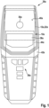
- Figure 1 shows a handheld tool 36a designed as a handheld locating device with a handheld tool device 10a according to the invention, a display unit 38a, an operating unit 39a, and a handheld tool housing 42a.
- the handheld tool housing 42a encloses an interior space in which the handheld tool device 10a is arranged.
- the display unit 38a and the operating unit 39a are arranged on a front side 40a of the handheld tool housing 42a.
- the handheld tool 36a is intended to be placed against a workpiece 14a with a rear side 41a during a locating process.
- the handheld tool device 10a can be configured by an operator using the operating unit 39a.
- the handheld tool device 10a outputs locating results to the operator via the display unit 38a.
- the hand tool device 10a comprises a first locating device 12a with four locating antennas 16a, 18a, 32a, 34a, a shielding means 20a, a second locating device 22a with a locating antenna 24a, and locating electronics 44a of the first and second locating devices 12a, 22a.
- the locating electronics 44a comprises, not shown in detail here, a computing unit and signal processing devices of the first and second locating devices 12a, 22a.
- the signal processing devices prepare the locating signals coming from the locating antennas 16a, 18a, 24a, 32a, 34a for the computing unit.
- the signal processing device of the first locating device 12a comprises a filter and an amplifier designed to filter out and amplify a received low-frequency locating signal.
- the locating antennas 16a, 18a, 24a, 32a, 34a are galvanically connected to a circuit board of the signal processing device.
- the locating antennas 16a, 18a, 24a, 32a, 34a could be connected to a circuit board of the signal processing device via a capacitive coupling.
- the signal processing device of the second locating device 22a comprises a filter and an amplifier designed to filter out and amplify a received high-frequency locating signal. Furthermore, the signal processing device of the second locating device 22a generates a locating signal that the locating antenna 24a of the second locating device 22a transmits.
- the computing unit determines location information from received location signals of a measurement object 46a arranged in a workpiece, which carries a low-frequency alternating voltage. Furthermore, the computing unit determines location information of additional measurement objects (not shown in detail) that reflect the location signal emitted by the location antenna 24a of the second location device 22a. Furthermore, the computing unit is designed to determine whether the additional measurement objects carry the low-frequency alternating voltage.
- the shielding means 20a is formed as a metallic layer applied to the inner side of a carrier 52a of the hand tool device 10a.
- the shielding means 20a is formed as a tube extending perpendicular to the front side 40a of the hand tool housing 42a.
- the shielding means 20a has an octagonal cross-section on a plane oriented parallel to the front side 40a of the hand tool housing 42a.
- the individual surfaces 48a of the shielding means 20a are conductively connected to one another along abutting edges 50a of the surfaces 48a.
- the four locating antennas 16a, 18a, 32a, 34a of the first locating device 12a are formed as metallic, electrically conductive layers applied to an outer side of the carrier 52a.
- the four locating antennas 16a, 18a, 32a, 34a are each offset by 90 degrees from the adjacent locating antennas 16a, 18a, 32a, 34a.
- the shielding means 20a is arranged between the locating antennas 16a, 18a, 32a, 34a.
- the locating antennas 16a, 18a, 32a, 34a of the first locating device 12a are arranged symmetrically to the shielding means 20a.
- the shielding means 20a completely encloses the locating antenna 24a of the second locating device 22a on planes aligned parallel to the front side 40a of the hand tool housing 42a.
- the locating antenna 24a of the second locating device 22a is designed to transmit a high-frequency locating signal. and receive.
- the hand-held tool device 10a includes a ground plane 54a, which is arranged between the front side 40a of the hand-held tool housing 42a and the locating antenna 24a of the second locating device 22a. Furthermore, the ground plane 54a is arranged between the locating antennas 16a, 18a, 32a, 34a of the first locating device 12a and the front side 40a of the hand-held tool housing 42a.
- the ground plane 54a and the shielding means 20a are electrically separated from one another. Here, there is a gap between the ground plane 54a and the shielding means 20a.
- the locating antenna 24a of the second locating device 22a and the hand tool housing 42a have a functional opening 30a.
- a functional means (not shown in detail) can be guided through the functional opening 30a perpendicular to the front side 40a of the hand tool housing 42a through the hand tool 36a to the workpiece 14a.
- the locating antennas 16a, 18a, 32a, 34a of the first locating device 12a are arranged symmetrically to the locating antenna 24a of the second locating device 22a and the functional opening 30a.
- the locating antenna 24a of the second locating device 22a has a main locating direction 28a oriented perpendicular to the rear side 41a of the handheld tool housing 42a.
- the locating antennas 16a, 18a, 32a, 34a of the first locating device 12a have main locating directions 56a, 58a, 60a, 62a directed away from the shielding means 20a. Furthermore, the main locating directions 56a, 58a, 60a, 62a are directed away from the ground plane 54a. Thus, the main locating directions 56a, 58a, 60a, 62a form an angle 64a of approximately 45 degrees to the rear side 41a of the handheld tool housing 42a.
- the locating antennas 16a, 18a, 32a, 34a of the first locating device 12a By varying the distances of the locating antennas 16a, 18a, 32a, 34a of the first locating device 12a from the shielding means 20a and/or from the ground plane 54a, other main locating directions are possible, which appear appropriate to a person skilled in the art.
- the main locating directions of the locating antennas 16a, 18a, 32a, 34a of the first locating device 12a could be aligned parallel to the rear side 41a of the hand tool housing 42a.
- the locating antennas 16a, 18a, 32a, 34a of the first locating device 12a have main extension planes that are parallel to the main locating direction. 28a of the locating antenna 24a of the second locating device 22a.
- FIG 4 shows a hand tool 36b with a hand tool device 10b and a hand tool housing 42b.
- the hand tool device 10b comprises a locating device 12b and a shielding means 20b.
- the locating device 12b is intended to locate a low-frequency alternating voltage of a measurement object 46b in a workpiece 14b.
- the locating device 12b has a first locating antenna 16b and a second locating antenna 18b.
- the shielding means 20b is intended to shield a low-frequency locating signal.
- the shielding means 20b is arranged between the first locating antenna 16b and the second locating antenna 18b.
- the shielding means 20b is formed as a layer whose main extension plane is aligned parallel to a rear side 41b of the hand tool housing 42b.
- the locating antennas 16b, 18b of the locating device 12b are each formed as a layer, the main extension plane of which is aligned perpendicular to the rear side 41b of the hand tool housing 42
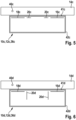
- Figure 5 should not be construed as an embodiment of the invention.
- Figure 5 shows a hand tool 36c with a hand tool device 10c and a hand tool housing 42c.
- the hand tool device 10c comprises a locating device 12c and a shielding means 20c.
- the locating device 12c is provided to locate a low-frequency alternating voltage of a measurement object 46c in a workpiece 14c.
- the locating device 12c has a first locating antenna 16c and a second locating antenna 18c.
- the shielding means 20c is provided to shield a low-frequency locating signal.
- the shielding means 20c is arranged between the first locating antenna 16c and the second locating antenna 18c.
- the shielding means 20c is designed as a Layer is formed, the main extension plane of which is aligned parallel to the rear side 41c of the hand tool housing 42c.
- FIG. 6 shows a hand tool 36d with a hand tool device 10d and a hand tool housing 42d.
- the hand tool device 10d comprises a locating device 12d and a shielding means 20d.
- the locating device 12d is intended to locate a low-frequency alternating voltage of a measurement object 46d in a workpiece 14d.
- the locating device 12d has a first locating antenna 16d and a second locating antenna 18d.
- the shielding means 20d is intended to shield a low-frequency locating signal.
- the shielding means 20d is arranged between the first locating antenna 16d and the second locating antenna 18d.
- the shielding means 20d is formed as a layer whose main extension is oriented perpendicular to a rear side 41d of the hand tool housing 42d.
- the locating antennas 16d, 18d of the locating device 12d are each formed as a layer, the main extension plane of which is aligned parallel to the rear side 41d of the hand tool housing 42d
Landscapes
- Life Sciences & Earth Sciences (AREA)
- Physics & Mathematics (AREA)
- Engineering & Computer Science (AREA)
- Remote Sensing (AREA)
- General Physics & Mathematics (AREA)
- Environmental & Geological Engineering (AREA)
- Geology (AREA)
- General Life Sciences & Earth Sciences (AREA)
- Geophysics (AREA)
- Electromagnetism (AREA)
- Measurement Of Length, Angles, Or The Like Using Electric Or Magnetic Means (AREA)
- Auxiliary Devices For Machine Tools (AREA)
Description
- Es ist bereits eine Handwerkzeugvorrichtung mit zumindest einer Ortungsvorrichtung, die dazu vorgesehen ist, eine niederfrequente Wechselspannung in einem Werkstück zu orten und die eine erste Ortungsantenne und eine zweite Ortungsantenne aufweist, vorgeschlagen worden. Ferner sind bereits Handwerkzeugvorrichtungen mit Abschirmmitteln vorgeschlagen worden (vgl. beispielsweise
US 6,512,475 B1 ,WO 2006/098751 A2 oderUS 2010/085234 A1 ). - Aus der
US 2008/036644 A1 ist ein Radargerät zur Ortung von in einem Medium eingeschlossenen Objekten bekannt, mit zumindest einem Radar-Sensor, der ein erstes, hochfrequentes Detektionssignal zum Eingriff in ein zu untersuchendes Medium erzeugt, so dass durch Messung und Auswertung des reflektierten Detektionssignals des Radarsensors, Informationen über ein in dem Medium eingeschlossenes Objekt gewonnen werden können. - Die Erfindung geht aus von einer Handwerkzeugvorrichtung gemäß Anspruch 1 mit zumindest einer Ortungsvorrichtung, die dazu vorgesehen ist, eine niederfrequente Wechselspannung in einem Werkstück zu orten und die eine erste Ortungsantenne und eine zweite Ortungsantenne aufweist.
- Es wird vorgeschlagen, dass die Handwerkzeugvorrichtung ein Abschirmmittel zur Abschirmung eines niederfrequenten Ortungssignals aufweist, das zwischen der ersten Ortungsantenne und der zweiten Ortungsantenne angeordnet ist. Unter einer "Ortungsvorrichtung" soll insbesondere eine Vorrichtung verstanden werden, die dazu vorgesehen ist, zumindest eine Ortsinformation über ein in einem Werkstück angeordnetes Messobjekt zu bestimmen. Vorzugsweise weist die Ortungsvorrichtung eine Recheneinheit auf, die dazu vorgesehen ist, zumindest eine Richtung und/oder eine Entfernung des Messobjekts relativ zu der Ortungsvorrichtung zu bestimmen. Bevorzugt weist die Ortungsvorrichtung ein Ausgabemittel auf, über das die Ortungsvorrichtung die Ortsinformation an einen Bediener ausgibt. Insbesondere soll unter "vorgesehen" speziell programmiert, ausgelegt und/oder ausgestattet verstanden werden. Unter einer "niederfrequenten Wechselspannung" soll insbesondere eine Spannung mit einer Frequenz kleiner als 100 kHz, vorteilhaft kleiner als 10 kHz, besonders vorteilhaft kleiner als 1 kHZ, verstanden werden. Vorzugsweise ist die Ortungsvorrichtung dazu vorgesehen, eine Netzspannung mit 50 Hz und/oder 60 Hz zu orten. Insbesondere soll unter der Wendung "in einem Werkstück" verstanden werden, dass die Ortungsvorrichtung dazu vorgesehen ist, das innerhalb von und/oder hinter dem Werkstück verdeckt angeordnete Messobjekt zu orten. Vorzugsweise ist die Ortungsvorrichtung dazu vorgesehen, ein Ortungssignal, das das Werkstück durchdrungen hat, zu empfangen. Unter "orten" soll insbesondere eine Bestimmung zumindest einer Ortsinformation eines entfernt und verdeckt angeordneten Messobjekts verstanden werden. Insbesondere soll unter einer "Ortungsantenne" ein Mittel verstanden werden, das dazu vorgesehen ist, ein elektrisch, magnetisch und/oder elektromagnetisch übertragenes Ortungssignal in ein von einem elektrischen Leiter übertragenes Signal zu wandeln. Unter einem "Abschirmmittel" soll insbesondere ein Mittel verstanden werden, das dazu vorgesehen ist, ein aus einer Richtung auf die Ortungsantenne wirkendes niederfrequentes Ortungssignal um mehr als 6 dB, vorteilhaft um mehr als 10 dB, besonders vorteilhaft um mehr als 20 dB, abzuschwächen. Insbesondere beeinflusst das Abschirmmittel eine Hauptortungsrichtung der Ortungsantennen. Vorzugsweise ist das Abschirmmittel als eine elektrisch leitende Schicht ausgebildet. Alternativ oder zusätzlich könnte das Abschirmmittel ein leitendes Gitter, leitende Streifen, leitende Teilflächen und/oder andere, dem Fachmann als sinnvoll erscheinende leitende Elemente aufweisen. Bevorzugt ist das Abschirmmittel als ein Blech und/oder vorteilhaft als eine Beschichtung eines Isolators, beispielsweise als ein metallisiertes Kunststoffteil oder als eine Leiterplatte, ausgebildet. Beispielsweise könnte das Abschirmmittel Kupfer, Eisen, Ferrit und/oder Mumetall aufweisen. Vorzugsweise weist das Abschirmmittel ein festes elektrisches Potential auf, beispielsweise könnte es mit einer Masse der Ortungsvorrichtung elektrisch leitend verbunden sein. Alternativ könnte es gegenüber der Ortungsvorrichtung elektrisch isoliert sein. Insbesondere soll unter einem "niederfrequenten Ortungssignal" ein Signal mit einer Frequenz kleiner als 1 kHz verstanden werden. Unter dem Begriff "zwischen" soll in diesem Zusammenhang insbesondere verstanden werden, dass das Abschirmmittel auf zumindest einer Geraden liegt, die auf zwei entgegengesetzten Seiten des Abschirmmittels jeweils eine der Ortungsantennen schneidet. Vorzugsweise liegt das Abschirmmittel zwischen jedem Punkt der ersten Ortungsantennen und, von dem Punkt ausgehend, zumindest 50 %, vorteilhaft 75 %, besonders vorteilhaft 90 %, einer Fläche der zweiten Ortungsantenne. Durch die erfindungsgemäße Ausgestaltung der Handwerkzeugvorrichtung kann konstruktiv einfach erreicht werden, dass Hauptortungsrichtungen der Ortungsantennen unterschiedlich ausgerichtet sind.
- Dadurch kann eine besonders vorteilhafte Ortsbestimmung der niederfrequenten Wechselspannung erreicht werden.
- In einer weiteren Ausgestaltung wird vorgeschlagen, dass die Ortungsantennen symmetrisch zu dem Abschirmmittel angeordnet sind, wodurch eine besonders einfache Bestimmung der Ortsinformation mit einer Recheneinheit möglich ist. Unter "symmetrisch angeordnet" soll insbesondere verstanden werden, dass Mittelpunkte der Ortungsantennen relativ zu einer durch einen Mittelpunkt des Abschirmmittels laufenden Symmetriefläche regelmäßig angeordnet sind.
- Des Weiteren wird vorgeschlagen, dass die erste und/oder die zweite Ortungsantenne von einer leitenden Schicht gebildet ist, wodurch eine besonders kostengünstige Fertigung möglich ist. Des Weiteren lassen sich die Ortungsantennen besonders platzsparend platzieren. Unter einer "leitenden Schicht" soll insbesondere ein leitender Bereich verstanden werden, dessen Dicke weniger als 10 % einer Höhe und eine Breite des Bereichs beträgt. Vorzugsweise sind die Ortungsantennen jeweils als ein Blech und/oder vorteilhaft als eine Beschichtung eines Isolators, beispielsweise als ein metallisiertes Kunststoffteil oder als eine Leiterplatte, ausgebildet.
- Ferner wird vorgeschlagen, dass die Handwerkzeugvorrichtung eine zweite Ortungsvorrichtung mit zumindest einer Ortungsantenne umfasst, wobei das Abschirmmittel die Ortungsantenne der zweite Ortungsvorrichtung zumindest im Wesentlichen umschließt, wodurch konstruktiv einfach in eine weitere Ortungsrichtung geortet werden kann. Insbesondere soll unter der Wendung "auf wenigstens einer Ebene zumindest im Wesentlichen umschließen" verstanden werden, dass von dem Mittelpunkt der Ortungsantenne ausgehende Strahlen, die auf der Ebene angeordnet sind, das Abschirmmittel über einem Winkelbereich von mehr als 180 Grad, vorteilhaft mehr als 270 Grad schneiden. Besonders vorteilhaft umschließt das Abschirmmittel die Ortungsantenne der dritten Ortungsvorrichtung um 360 Grad.
- Zudem wird vorgeschlagen, dass die zweite Ortungsvorrichtung dazu vorgesehen ist, mit einem hochfrequenten Ortungssignal zu orten, wodurch spannungsfreie Messobjekte vorteilhaft geortet werden können. Vorzugsweise ist die Ortungsantenne der zweiten Ortungsvorrichtung wie in der Druckschrift
DE 10 2008 041 651 A1 beschrieben ausgebildet. Alternativ oder zusätzlich könnte die Ortungsantenne der zweiten Ortungsvorrichtung dazu vorgesehen sein, ein Messobjekt induktiv und/oder kapazitiv zu orten. Des Weiteren könnte die zweite Ortungsvorrichtung dazu vorgesehen sein, eine niederfrequente Wechselspannung zu orten. Insbesondere soll unter einem "hochfrequenten Ortungssignal" ein Ortungssignal mit einer Frequenz größer als 1 KHz, vorteilhaft größer als 1 MHz, verstanden werden. Vorzugsweise ist die dritte Ortungsvorrichtung dazu vorgesehen, mit einem Ultrabreitbandsignal zu orten. Unter einem "Ultrabreitbandsignal" soll insbesondere ein Ortungssignal mit einer Mittelfrequenz im Frequenzbereich von 250 MHz bis 15 GHz und einer Frequenzbandbreite von zumindest 500 MHz verstanden werden. Alternativ oder zusätzlich könnte die zweite Ortungsvorrichtung dazu vorgesehen sein, mit einem smallbandigen Ortungssignal zu orten. - Weiterhin wird vorgeschlagen, dass die erste und die zweite Ortungsantenne symmetrisch zu der Ortungsantenne der zweiten Ortungsvorrichtung angeordnet sind, wodurch eine besonders einfache Bestimmung der Ortsinformation mit einer Recheneinheit möglich ist.
- In einer vorteilhaften Ausbildung der Erfindung wird vorgeschlagen, dass die erste und die zweite Ortungsantenne eine Haupterstreckung aufweisen, die im Wesentlichen parallel zu einer Hauptortungsrichtung der Ortungsantenne der zweiten Ortungsvorrichtung ausgerichtet ist, wodurch eine besonders platzsparende Ausgestaltung der Handwerkzeugvorrichtung erreicht werden kann. Unter einer "Haupterstreckungsebene" soll insbesondere eine Ebene mit einer maximalen Erstreckung verstanden werden. Insbesondere soll unter "im Wesentlichen parallel" verstanden werden, dass eine Erstreckung der Haupterstreckungsebene weniger als 20 Grad, vorteilhaft weniger als 10 Grad, von der Hauptortungsrichtung abweicht. Unter einer "Hauptortungsrichtung" soll insbesondere eine Richtung verstanden werden, in der die Ortungsantenne eine maximale Empfindlichkeit aufweist. Bei einer Ortungsantenne, die dazu vorgesehen ist, eine maximale Energie in unterschiedlichen Betriebszuständen in unterschiedliche Richtungen auszusenden, soll unter der "Hauptortungsrichtung" vorteilhaft eine mittlere Richtung der unterschiedlichen Richtungen verstanden werden.
- Des Weiteren wird vorgeschlagen, dass die Handwerkzeugvorrichtung eine FunktionsÖffnung aufweist, wobei zumindest zwei der Ortungsantennen, insbesondere die Ortungsantennen der ersten und einer zweiten Ortungsvorrichtung, symmetrisch zu der Funktionsöffnung angeordnet sind, wodurch das Werkstück komfortabel an einer Stelle bearbeitet und/oder markiert werden kann, an der eine Ortung durchgeführt wurde. Unter einer "Funktionsöffnung" soll insbesondere eine Öffnung der Handwerkzeugvorrichtung verstanden werden, durch die ein Funktionsmittel, beispielsweise ein Bohrer und/oder ein Stift, zu dem Werkstück geführt werden kann, während ein Gehäuse eines die Handwerkzeugvorrichtung aufweisenden Geräts mit einer Ortungsseite an das Werkstück angelegt ist.
- Ferner wird vorgeschlagen, dass die erste Ortungsvorrichtung eine dritte Ortungsantenne und eine vierte Ortungsantenne aufweist, wobei das Abschirmmittel zwischen der dritten Ortungsantenne und der vierten Ortungsantenne angeordnet ist, wodurch eine besonders genaue Ortung der niederfrequenten Wechselspannung möglich ist.
- Des Weiteren geht die Erfindung aus von einem Handwerkzeug mit einer Handwerkzeugvorrichtung. Insbesondere soll unter einem "Handwerkzeug" ein, dem Fachmann als sinnvoll erscheinendes Werkzeug, vorteilhaft jedoch eine Bohrmaschine, ein Bohrhammer, ein Schlaghammer, eine Säge, ein Hobel, ein Schrauber, eine Fräse, ein Schleifer, ein Winkelschleifer, ein Gartengerät, ein Multifunktionswerkzeug und/oder besonders vorteilhaft ein Baustellenmessgerät verstanden werden.
- Weitere Vorteile ergeben sich aus der folgenden Zeichnungsbeschreibung. In der Zeichnung sind vier Ausführungsbeispiele der Erfindung dargestellt. Die Zeichnung, die Beschreibung und die Ansprüche enthalten zahlreiche Merkmale in Kombination. Der Fachmann wird die Merkmale zweckmäßigerweise auch einzeln betrachten und zu sinnvollen weiteren Kombinationen zusammenfassen.
- Es zeigen:
- Fig. 1
- ein Handwerkzeug mit einer erfindungsgemäße Handwerkzeugvorrichtung,
- Fig. 2
- vier Ortungsantennen einer ersten Ortungsvorrichtung, eine Ortungsantenne einer zweiten Ortungsvorrichtung und ein Abschirmmittel der Handwerkzeugvorrichtung aus
Figur 1 in einer perspektivischen Ansicht, - Fig. 3
- einen schematischen Schnitt der Handwerkzeugvorrichtung aus
Figur 1 , - Fig. 4
- einen schematischen Schnitt eines zweiten, alternativen Ausführungsbeispiels der Handwerkzeugvorrichtung aus
Figur 1 , - Fig. 5
- einen schematischen Schnitt eines dritten, alternativen Ausführungsbeispiels der Handwerkzeugvorrichtung aus
Figur 1 , das kein Bestandteil der vorliegenden Erfindung ist und - Fig. 6
- einen schematischen Schnitt eines vierten, alternativen Ausführungsbeispiels der Handwerkzeugvorrichtung aus
Figur 1 . -
Figur 1 zeigt ein als Handortungsgerät ausgebildetes Handwerkzeug 36a mit einer erfindungsgemäßen Handwerkzeugvorrichtung 10a, einer Anzeigeeinheit 38a, einer Bedieneinheit 39a und einem Handwerkzeuggehäuse 42a. Das Handwerkzeuggehäuse 42a umschließt einen Innenraum, in dem die Handwerkzeugvorrichtung 10a angeordnet ist. Die Anzeigeeinheit 38a und die Bedieneinheit 39a sind auf einer Vorderseite 40a des Handwerkzeuggehäuses 42a angeordnet. Das Handwerkzeug 36a ist dazu vorgesehen, bei einem Ortungsvorgang mit einer Rückseite 41a an ein Werkstück 14a angelegt zu werden. Mittels der Bedieneinheit 39a ist die Handwerkzeugvorrichtung 10a von einem Bediener konfigurierbar. Die Handwerkzeugvorrichtung 10a gibt über die Anzeigeeinheit 38a Ortungsergebnisse an den Bediener aus. - Wie die
Figuren 2 und3 zeigen, umfasst die Handwerkzeugvorrichtung 10a eine erste Ortungsvorrichtung 12a mit vier Ortungsantennen 16a, 18a, 32a, 34a, ein Abschirmmittel 20a, eine zweite Ortungsvorrichtung 22a mit einer Ortungsantenne 24a und eine Ortungselektronik 44a der ersten und der zweiten Ortungsvorrichtung 12a, 22a. Die Ortungselektronik 44a umfasst, hier nicht näher dargestellt, eine Recheneinheit und Signalverarbeitungsvorrichtungen der ersten und der zweiten Ortungsvorrichtung 12a, 22a. - Die Signalverarbeitungsvorrichtungen bereiten von den Ortungsantennen 16a, 18a, 24a, 32a, 34a kommende Ortungssignale für die Recheneinheit auf. Die Signalverarbeitungsvorrichtung der ersten Ortungsvorrichtung 12a umfasst einen Filter und einen Verstärker, die dazu vorgesehen sind, ein empfangenes niederfrequentes Ortungssignal herauszufiltern und zu verstärken. Die Ortungsantennen 16a, 18a, 24a, 32a, 34a sind galvanisch mit einer Leiterplatte der Signalverarbeitungsvorrichtung verbunden. Alternativ könnten die Ortungsantennen 16a, 18a, 24a, 32a, 34a über eine kapazitive Kopplung mit einer Leiterplatte der Signalverarbeitungsvorrichtung verbunden sein.
- Die Signalverarbeitungsvorrichtung der zweiten Ortungsvorrichtung 22a umfasst einen Filter und einen Verstärker, die dazu vorgesehen sind, ein empfangenes hochfrequentes Ortungssignal herauszufiltern und zu verstärken. Des Weiteren generiert die Signalverarbeitungsvorrichtung der zweiten Ortungsvorrichtung 22a ein Ortungssignal, das die Ortungsantenne 24a der zweiten Ortungsvorrichtung 22a aussendet.
- Die Recheneinheit bestimmt aus empfangenen Ortungssignalen Ortsinformationen von einem in einem Werkstück angeordneten Messobjekt 46a, das eine niederfrequente Wechselspannung führt. Des Weiteren bestimmt die Recheneinheit Ortsinformationen von weiteren nicht näher dargestellten Messobjekten, die das von der Ortungsantenne 24a der zweiten Ortungsvorrichtung 22a ausgesendete Ortungssignal reflektieren. Zudem ist die Recheneinheit dazu vorgesehen zu bestimmen, ob die weiteren Messobjekte die niederfrequente Wechselspannung führen.
- . Das Abschirmmittel 20a ist als eine auf eine Innenseite eines Trägers 52a der Handwerkzeugvorrichtung10a aufgetragene metallische Schicht ausgebildet. Das Abschirmmittel 20a ist als eine senkrecht zu der Vorderseite 40a des Handwerkzeuggehäuses 42a verlaufende Röhre ausgebildet. Das Abschirmmittel 20a weist einen achteckigen Querschnitt auf einer Ebene auf, die parallel zu der Vorderseite 40a des Handwerkzeuggehäuses 42a ausgerichtet ist. Die einzelnen Flächen 48a des Abschirmmittels 20a sind entlang von Stoßkanten 50a der Flächen 48a leitend miteinander verbunden
- Die vier Ortungsantennen 16a, 18a, 32a, 34a der ersten Ortungsvorrichtung 12a sind als auf eine Außenseite des Trägers 52a aufgetragene metallische, elektrisch leitende Schichten ausgebildet. Die vier Ortungsantennen 16a, 18a, 32a, 34a sind zu der jeweils benachbart angeordneten Ortungsantenne 16a, 18a, 32a, 34a jeweils um 90 Grad versetzt angeordnet. Somit ist das Abschirmmittel 20a jeweils zwischen den Ortungsantennen 16a, 18a, 32a, 34a angeordnet. Die Ortungsantennen 16a, 18a, 32a, 34a der ersten Ortungsvorrichtung 12a sind symmetrisch zu dem Abschirmmittel 20a angeordnet.
- Das Abschirmmittel 20a umschließt die Ortungsantenne 24a der zweite Ortungsvorrichtung 22a auf Ebenen, die parallel zu der Vorderseite 40a des Handwerkzeuggehäuses 42a ausgerichtet sind, vollständig. Die Ortungsantenne 24a der zweiten Ortungsvorrichtung 22a ist dazu vorgesehen, ein hochfrequentes Ortungssignal auszusenden und zu empfangen. Die Handwerkzeugvorrichtung 10a umfasst eine Massefläche 54a, die zwischen der Vorderseite 40a des Handwerkzeuggehäuses 42a und der Ortungsantenne 24a der zweiten Ortungsvorrichtung 22a angeordnet ist. Des Weiteren ist die Massefläche 54a zwischen den Ortungsantennen 16a, 18a, 32a, 34a der ersten Ortungsvorrichtung 12a und der Vorderseite 40a des Handwerkzeuggehäuse 42a angeordnet. Die Massefläche 54a und das Abschirmmittel 20a sind elektrisch voneinander getrennt. Hier ist zwischen der Massefläche 54a und dem Abschirmmittel 20a ein Spalt.
- Die Ortungsantenne 24a der zweite Ortungsvorrichtung 22a und das Handwerkzeuggehäuse 42a weisen eine Funktionsöffnung 30a auf. Durch die Funktionsöffnung 30a kann ein nicht näher dargestelltes Funktionsmittel senkrecht zu der Vorderseite 40a des Handwerkzeuggehäuses 42a durch das Handwerkzeug 36a zu dem Werkstück 14a geführt werden. Die Ortungsantennen 16a, 18a, 32a, 34a der ersten Ortungsvorrichtung 12a sind symmetrisch zu der Ortungsantenne 24a der zweiten Ortungsvorrichtung 22a und der Funktionsöffnung 30a angeordnet.
- Die Ortungsantenne 24a der zweiten Ortungsvorrichtung 22a weist eine Hauptortungsrichtung 28a auf, die senkrecht zu der Rückseite 41a des Handwerkzeuggehäuses 42a ausgerichtet ist. Die Ortungsantennen 16a, 18a, 32a, 34a der ersten Ortungsvorrichtung 12a weisen Hauptortungsrichtungen 56a, 58a, 60a, 62a auf, die von dem Abschirmmittel 20a weg gerichtet sind. Des Weiteren sind die Hauptortungsrichtungen 56a, 58a, 60a, 62a von der Massefläche 54a weg gerichtet. Somit weisen die Hauptortungsrichtungen 56a, 58a, 60a, 62a zu der Rückseite 41a des Handwerkzeuggehäuses 42a einen Winkel 64a von etwa 45 Grad auf. Durch unterschiedliche Abstände der Ortungsantennen 16a, 18a, 32a, 34a der ersten Ortungsvorrichtung 12a zu dem Abschirmmittel 20a und/oder zu der Massefläche 54a sind andere, dem Fachmann als sinnvoll erscheinende Hauptortungsrichtungen möglich. Alternativ könnten die Hauptortungsrichtungen der Ortungsantennen 16a, 18a, 32a, 34a der ersten Ortungsvorrichtung 12a parallel zu der Rückseite 41a des Handwerkzeuggehäuses 42a ausgerichtet sein. Die Ortungsantennen 16a, 18a, 32a, 34a der ersten Ortungsvorrichtung 12a weisen Haupterstreckungsebenen auf, die parallel zu der Hauptortungsrichtung 28a der Ortungsantenne 24a der zweiten Ortungsvorrichtung 22a ausgerichtet sind.
- In den
Figuren 4 und6 sind drei weitere Ausführungsbeispiele der Erfindung gezeigt. Die nachfolgenden Beschreibungen und die Zeichnungen beschränken sich im Wesentlichen auf die Unterschiede zwischen den Ausführungsbeispielen, wobei bezüglich gleich bezeichneter Bauteile, insbesondere in Bezug auf Bauteile mit gleichen Bezugszeichen, grundsätzlich auch auf die Zeichnungen und/oder die Beschreibung der anderen Ausführungsbeispiele, insbesondere derFiguren 1 bis 3 , verwiesen werden kann. Zur Unterscheidung der Ausführungsbeispiele ist der Buchstabe a den Bezugszeichen des Ausführungsbeispiels in denFiguren 1 bis 3 nachgestellt. In den Ausführungsbeispielen derFiguren 4 bis 6 ist der Buchstabe a durch die Buchstaben b bis d ersetzt. -
Figur 4 zeigt ein Handwerkzeug 36b mit einer Handwerkzeugvorrichtung 10b und einem Handwerkzeuggehäuse 42b. Die Handwerkzeugvorrichtung 10b umfasst eine Ortungsvorrichtung 12b und ein Abschirmmittel 20b. Die Ortungsvorrichtung 12b ist dazu vorgesehen, eine niederfrequente Wechselspannung eines Messobjekts 46b in einem Werkstück 14b zu orten. Die Ortungsvorrichtung 12b weist eine erste Ortungsantenne 16b und eine zweite Ortungsantenne 18b auf. Das Abschirmmittel 20b ist dazu vorgesehen, ein niederfrequentes Ortungssignal abzuschirmen. Das Abschirmmittel 20b ist zwischen der ersten Ortungsantenne 16b und der zweiten Ortungsantenne 18b angeordnet. Das Abschirmmittel 20b ist als eine Schicht ausgebildet, deren Haupterstreckungsebene parallel zu einer Rückseite 41b des Handwerkzeuggehäuses 42b ausgerichtet ist. Die Ortungsantennen 16b, 18b der Ortungsvorrichtung 12b sind jeweils als eine Schicht ausgebildet, deren Haupterstreckungsebene jeweils senkrecht zu der Rückseite 41b des Handwerkzeuggehäuses 42b ausgerichtet ist. -
Figur 5 soll nicht als eine Ausführungsform der Erfindung aufgefasst werden.Figur 5 zeigt ein Handwerkzeug 36c mit einer Handwerkzeugvorrichtung 10c und einem Handwerkzeuggehäuse 42c. Die Handwerkzeugvorrichtung 10c umfasst eine Ortungsvorrichtung 12c und ein Abschirmmittel 20c. Die Ortungsvorrichtung 12c ist dazu vorgesehen, eine niederfrequente Wechselspannung eines Messobjekts 46c in einem Werkstück 14c zu orten. Die Ortungsvorrichtung 12c weist eine erste Ortungsantenne 16c und eine zweite Ortungsantenne 18c auf. Das Abschirmmittel 20c ist dazu vorgesehen, ein niederfrequentes Ortungssignal abzuschirmen. Das Abschirmmittel 20c ist zwischen der ersten Ortungsantenne 16c und der zweiten Ortungsantenne 18c angeordnet. Das Abschirmmittel 20c ist als eine Schicht ausgebildet, deren Haupterstreckungsebene jeweils parallel zu der Rückseite 41c des Handwerkzeuggehäuses 42c ausgerichtet ist. -
Figur 6 zeigt ein Handwerkzeug 36d mit einer Handwerkzeugvorrichtung 10d und einem Handwerkzeuggehäuse 42d. Die Handwerkzeugvorrichtung 10d umfasst eine Ortungsvorrichtung 12d und ein Abschirmmittel 20d. Die Ortungsvorrichtung 12d ist dazu vorgesehen, eine niederfrequente Wechselspannung eines Messobjekts 46d in einem Werkstück 14d zu orten. Die Ortungsvorrichtung 12d weist eine erste Ortungsantenne 16d und eine zweite Ortungsantenne 18d auf. Das Abschirmmittel 20d ist dazu vorgesehen, ein niederfrequentes Ortungssignal abzuschirmen. Das Abschirmmittel 20d ist zwischen der ersten Ortungsantenne 16d und der zweiten Ortungsantenne 18d angeordnet. Das Abschirmmittel 20d ist als eine Schicht ausgebildet, deren Haupterstreckung senkrecht zu einer Rückseite 41d des Handwerkzeuggehäuses 42d ausgerichtet ist. Die Ortungsantennen 16d, 18d der Ortungsvorrichtung 12d sind jeweils als eine Schicht ausgebildet, deren Haupterstreckungsebene jeweils parallel zu der Rückseite 41d des Handwerkzeuggehäuses 42d ausgerichtet ist.
Claims (12)
- Handwerkzeugvorrichtung mit zumindest einer Ortungsvorrichtung (12a-d), die dazu vorgesehen ist, eine niederfrequente Wechselspannung in einem Werkstück (14a-d) zu orten und die zumindest eine erste Ortungsantenne (16a-d), eine zweite Ortungsantenne (18a-d) und ein Abschirmmittel (20a-d) zur Abschirmung eines niederfrequenten Ortungssignals aufweist, das zwischen der ersten Ortungsantenne (16a-d) und der zweiten Ortungsantenne (18a-d) angeordnet ist, wobei die erste und die zweite Ortungsantenne (16a-d; 18a-d) sich entlang paralleler Flächen erstrecken, dadurch gekennzeichnet, dass mindestens ein Teil des Abschirmmittels (20a-d) senkrecht zu den Ortungsantennen (16a-d; 18a-d) verläuft, so dass das Abschirmmittel (20a-d) Hauptortungsrichtungen (56a, 58a, 60a, 62a) der Ortungsantennen (16a-d, 18a-d), d.h. solche Richtungen, in denen eine jeweilige Ortungsantenne eine maximale Empfindlichkeit aufweist, beeinflusst.
- Handwerkzeugvorrichtung nach Anspruch 1, dadurch gekennzeichnet, dass das Abschirmmittel (20a-d) derart angeordnet ist, dass Hauptortungsrichtungen (56a, 58a, 60a, 62a) der Ortungsantennen (16a-d, 18a-d) in unterschiedliche Richtungen ausgerichtet sind.
- Handwerkzeugvorrichtung nach einem der vorhergehenden Ansprüche, gekennzeichnet durch eine Recheneinheit, die aus von den Ortungsantennen (16a, 18a) in Hauptortungsrichtungen (56a, 58a, 60a, 62a) empfangenen Ortungssignalen Ortsinformationen von einem in einem Werkstück angeordneten Messobjekt 46a, das eine niederfrequente Wechselspannung führt, bestimmt.
- Handwerkzeugvorrichtung nach einem der vorhergehenden Ansprüche, dadurch gekennzeichnet, dass die Ortungsantennen (16a-d, 18a-d) symmetrisch zu dem Abschirmmittel (20a-d) angeordnet sind.
- Handwerkzeugvorrichtung nach einem der vorhergehenden Ansprüche, dadurch gekennzeichnet, dass die erste und/oder die zweite Ortungsantenne (16a-d, 18a-d) von einer leitenden Schicht gebildet ist.
- Handwerkzeugvorrichtung nach einem der vorhergehenden Ansprüche, gekennzeichnet durch eine zweite Ortungsvorrichtung (22a) mit zumindest einer Ortungsantenne (24a), wobei das Abschirmmittel (20a) die Ortungsantenne (24a) der zweiten Ortungsvorrichtung (22a) zumindest im Wesentlichen umschließt.
- Handwerkzeugvorrichtung nach Anspruch 6, dadurch gekennzeichnet, dass die zweite Ortungsvorrichtung (22a) dazu vorgesehen ist, mit einem hochfrequenten Ortungssignal zu orten.
- Handwerkzeugvorrichtung zumindest nach Anspruch 6, dadurch gekennzeichnet, dass die erste und die zweite Ortungsantenne (16a, 18a) symmetrisch zu der Ortungsantenne (24a) der zweiten Ortungsvorrichtung (22a) angeordnet sind.
- Handwerkzeugvorrichtung zumindest nach Anspruch 6, dadurch gekennzeichnet, dass die erste und die zweite Ortungsantenne (16a, 18a) eine Haupterstreckungsebene aufweisen, die im Wesentlichen parallel zu einer Hauptortungsrichtung (28a) der Ortungsantenne (24a) der zweiten Ortungsvorrichtung (22a) ausgerichtet ist.
- Handwerkzeugvorrichtung nach einem der vorhergehenden Ansprüche, gekennzeichnet durch eine Funktionsöffnung (30a), wobei zumindest zwei der Ortungsantennen (16a, 18a) symmetrisch zu der Funktionsöffnung (30a) angeordnet sind.
- Handwerkzeugvorrichtung nach einem der vorhergehenden Ansprüche, dadurch gekennzeichnet, dass die erste Ortungsvorrichtung (12a) eine dritte Ortungsantenne (32a) und eine vierte Ortungsantenne (34a) aufweist, wobei das Abschirmmittel (20a) zwischen der dritten Ortungsantenne (32a) und der vierten Ortungsantenne (34) angeordnet ist.
- Handwerkzeug mit einer Handwerkzeugvorrichtung (10a-d) nach einem der vorhergehenden Ansprüche.
Applications Claiming Priority (2)
| Application Number | Priority Date | Filing Date | Title |
|---|---|---|---|
| DE102012210009A DE102012210009A1 (de) | 2012-06-14 | 2012-06-14 | Handwerkzeugvorrichtung |
| PCT/EP2013/057789 WO2013185947A1 (de) | 2012-06-14 | 2013-04-15 | Handwerkzeugvorrichtung |
Publications (2)
| Publication Number | Publication Date |
|---|---|
| EP2862009A1 EP2862009A1 (de) | 2015-04-22 |
| EP2862009B1 true EP2862009B1 (de) | 2025-03-26 |
Family
ID=48141967
Family Applications (1)
| Application Number | Title | Priority Date | Filing Date |
|---|---|---|---|
| EP13717252.4A Active EP2862009B1 (de) | 2012-06-14 | 2013-04-15 | Handwerkzeugvorrichtung |
Country Status (5)
| Country | Link |
|---|---|
| US (1) | US20150160362A1 (de) |
| EP (1) | EP2862009B1 (de) |
| CN (1) | CN104350395B (de) |
| DE (1) | DE102012210009A1 (de) |
| WO (1) | WO2013185947A1 (de) |
Families Citing this family (3)
| Publication number | Priority date | Publication date | Assignee | Title |
|---|---|---|---|---|
| US10131042B2 (en) | 2013-10-21 | 2018-11-20 | Milwaukee Electric Tool Corporation | Adapter for power tool devices |
| FR3031682B1 (fr) | 2015-01-21 | 2019-11-29 | Clextral | Procede et installation de production d'un produit poreux en poudre |
| DE102016209253A1 (de) | 2015-11-24 | 2017-05-24 | Robert Bosch Gmbh | System aus zumindest einer Handwerkzeugmaschine, zumindest einer ersten Schnittstelle und zumindest einem elektrotechnischen Erzeugnis |
Citations (1)
| Publication number | Priority date | Publication date | Assignee | Title |
|---|---|---|---|---|
| US20080036644A1 (en) * | 2004-02-14 | 2008-02-14 | Uwe Skultety-Betz | Short-Range Radar Having A Multiple Sensor System For Determining The Location Of Objects Enclosed In A Medium |
Family Cites Families (20)
| Publication number | Priority date | Publication date | Assignee | Title |
|---|---|---|---|---|
| US6140819A (en) * | 1998-05-26 | 2000-10-31 | Heath Consultants, Inc. | Continuous-depth-indicating underground pipe and cable locator |
| US6211662B1 (en) * | 1998-08-07 | 2001-04-03 | The Stanley Works | Hand-held hidden object sensor for sensing a location of objects hidden behind a surface of an architectural structure |
| US6512475B1 (en) * | 1999-04-02 | 2003-01-28 | Geophysical Survey Systems, Inc. | High-frequency dual-channel ground-penetrating impulse antenna and method of using same for identifying plastic pipes and rebar in concrete |
| US20080196910A1 (en) * | 2000-06-20 | 2008-08-21 | Radle Patrick J | Electrical sensing device modules for attachment to power tools and drills |
| DE10050655C1 (de) * | 2000-10-13 | 2002-01-24 | Hilti Ag | GPR-Mehrfachantennen-Vorrichtung zur Materialerkundung für den kombinierten Einsatz mit einem Handwerkzeug |
| US6894508B2 (en) * | 2002-06-28 | 2005-05-17 | Solar Wide Industrial Ltd. | Apparatus and method for locating objects behind a wall lining |
| US7310060B2 (en) * | 2003-08-15 | 2007-12-18 | L-3 Communications Cyterra Corporation | Multi-mode landmine detector |
| US8174429B2 (en) * | 2003-08-15 | 2012-05-08 | L-3 Communications Cyterra Corporation | Mine detection |
| DE102004023330A1 (de) * | 2004-05-12 | 2005-12-08 | Robert Bosch Gmbh | Ortungsgerät sowie Verfahren zur Kalibrierung eines Ortungsgeräts |
| WO2006098751A2 (en) * | 2004-07-28 | 2006-09-21 | L-3 Communications Cyterra Corporation | Multi-mode landmine detector |
| DE102005000054A1 (de) * | 2005-05-10 | 2006-11-16 | Hilti Ag | Handgeführter, scannender Untergrunddetektor |
| DE102005052367A1 (de) * | 2005-10-31 | 2007-05-03 | Robert Bosch Gmbh | Messgerät und Verfahren zur Ortung von in einem Medium eingeschlossenen Objekten mittels elektromagnetischer HF-Signale |
| DE102005062874A1 (de) * | 2005-12-29 | 2007-07-05 | Robert Bosch Gmbh | Vorrichtung zum Senden und/oder Empfangen elektromagnetischer HF-Signale |
| DE102006025861A1 (de) * | 2006-06-02 | 2007-12-06 | Robert Bosch Gmbh | Ortungsgerät |
| US7449892B2 (en) * | 2006-06-02 | 2008-11-11 | Cal-Tek 2000, Inc. | Stray voltage detecting |
| IL180334A (en) * | 2006-12-26 | 2014-03-31 | Elta Systems Ltd | A method and system for monitoring underground electrical cables |
| DE102008041651A1 (de) | 2008-08-28 | 2010-03-04 | Robert Bosch Gmbh | Elektrogerät |
| DE102008043282A1 (de) * | 2008-10-29 | 2010-05-06 | Robert Bosch Gmbh | Ortungsvorrichtung |
| WO2011008647A2 (en) * | 2009-07-14 | 2011-01-20 | Connor Martin C | Electromagnetic antenna and method of use for detecting objects |
| WO2012024133A2 (en) * | 2010-08-20 | 2012-02-23 | Niitek, Inc. | Metal detector and ground-penetrating radar hybrid head and manufacturing method thereof |
-
2012
- 2012-06-14 DE DE102012210009A patent/DE102012210009A1/de not_active Withdrawn
-
2013
- 2013-04-15 WO PCT/EP2013/057789 patent/WO2013185947A1/de not_active Ceased
- 2013-04-15 US US14/406,230 patent/US20150160362A1/en not_active Abandoned
- 2013-04-15 EP EP13717252.4A patent/EP2862009B1/de active Active
- 2013-04-15 CN CN201380030967.8A patent/CN104350395B/zh active Active
Patent Citations (1)
| Publication number | Priority date | Publication date | Assignee | Title |
|---|---|---|---|---|
| US20080036644A1 (en) * | 2004-02-14 | 2008-02-14 | Uwe Skultety-Betz | Short-Range Radar Having A Multiple Sensor System For Determining The Location Of Objects Enclosed In A Medium |
Also Published As
| Publication number | Publication date |
|---|---|
| DE102012210009A1 (de) | 2013-12-19 |
| EP2862009A1 (de) | 2015-04-22 |
| CN104350395B (zh) | 2018-05-25 |
| WO2013185947A1 (de) | 2013-12-19 |
| US20150160362A1 (en) | 2015-06-11 |
| CN104350395A (zh) | 2015-02-11 |
Similar Documents
| Publication | Publication Date | Title |
|---|---|---|
| EP2319124B1 (de) | Elektrogerät | |
| EP1718998B1 (de) | Verfahren und messgerät zur ortung von in einem medium eingeschlossenen objekten | |
| EP0867971B1 (de) | Schlüsselloses Zugangssystem für ein Kraftfahrzeug mit einem Magnetfeldsensor | |
| WO2009083302A1 (de) | Ortungsgerät | |
| DE60031000T2 (de) | Bodendurchdringendes Radarsystem und Verfahren zur Erkennung eines Objektes auf oder unter einer Bodenfläche | |
| EP2621682B1 (de) | Ortungsvorrichtung | |
| EP2862009B1 (de) | Handwerkzeugvorrichtung | |
| DE102009000644A1 (de) | Vorrichtung zum Senden und/oder Empfangen elektromagnetischer HF-Signale, sowie Messgerät und Werkzeugmaschinenüberwachungsvorrichtung mit einer solchen Vorrichtung | |
| EP2621681B1 (de) | Handwerkzeugmaschinenvorrichtung | |
| DE102004031627A1 (de) | Verfahren und Vorrichtung zur werkstoffdurchdringenden Ortung eines Messsignals | |
| DE102004007316A1 (de) | Infrarot-Ortungsgerät mit Merhfachsensorik | |
| EP1360525A1 (de) | Ortungsgerät | |
| DE19962949A1 (de) | Vorrichtung zur abtaststrahlungsbasierten Oberflächenzustandserkennung insbesondere von Straßen | |
| EP2493656B1 (de) | Überwachungsvorrichtung einer werkzeugmaschine | |
| EP2791710B1 (de) | Handwerkzeugvorrichtung mit zumindest einer ortungsvorrichtung | |
| EP2621656B1 (de) | Ortungsvorrichtung | |
| DE202012006964U1 (de) | Schleifensystem für Metallsuchgeräte | |
| DE112021001460T5 (de) | Doppelseitige Platte, Radarvorrichtung, Übertragungselement, und Verfahren zum Herstellen eines Übertragungselements | |
| DE102012204580A1 (de) | Handortungsgerät | |
| DE112012002840T5 (de) | Vorrichtung zum Detektieren von Objekten, wie etwa Minen | |
| EP3232206A1 (de) | Sensorelement, sensorvorrichtung und verfahren zum detektieren von zumindest einer elektrischen leitung | |
| DE102006062492A1 (de) | Hochfrequenzsensor sowie Werkzeugmaschine mit einem Hochfrequenzsensor | |
| DE102008004417A1 (de) | Vorrichtung zum Senden und/oder Empfangen elektromagnetischer HF-Signale | |
| EP1181506B1 (de) | Messverfahren und vorrichtung zu dessen durchführung | |
| DE102015015386A1 (de) | Detektionsvorrichtung |
Legal Events
| Date | Code | Title | Description |
|---|---|---|---|
| PUAI | Public reference made under article 153(3) epc to a published international application that has entered the european phase |
Free format text: ORIGINAL CODE: 0009012 |
|
| 17P | Request for examination filed |
Effective date: 20150114 |
|
| AK | Designated contracting states |
Kind code of ref document: A1 Designated state(s): AL AT BE BG CH CY CZ DE DK EE ES FI FR GB GR HR HU IE IS IT LI LT LU LV MC MK MT NL NO PL PT RO RS SE SI SK SM TR |
|
| AX | Request for extension of the european patent |
Extension state: BA ME |
|
| DAX | Request for extension of the european patent (deleted) | ||
| STAA | Information on the status of an ep patent application or granted ep patent |
Free format text: STATUS: EXAMINATION IS IN PROGRESS |
|
| 17Q | First examination report despatched |
Effective date: 20180831 |
|
| RAP1 | Party data changed (applicant data changed or rights of an application transferred) |
Owner name: ROBERT BOSCH GMBH |
|
| GRAP | Despatch of communication of intention to grant a patent |
Free format text: ORIGINAL CODE: EPIDOSNIGR1 |
|
| STAA | Information on the status of an ep patent application or granted ep patent |
Free format text: STATUS: GRANT OF PATENT IS INTENDED |
|
| INTG | Intention to grant announced |
Effective date: 20241025 |
|
| GRAS | Grant fee paid |
Free format text: ORIGINAL CODE: EPIDOSNIGR3 |
|
| GRAA | (expected) grant |
Free format text: ORIGINAL CODE: 0009210 |
|
| STAA | Information on the status of an ep patent application or granted ep patent |
Free format text: STATUS: THE PATENT HAS BEEN GRANTED |
|
| AK | Designated contracting states |
Kind code of ref document: B1 Designated state(s): AL AT BE BG CH CY CZ DE DK EE ES FI FR GB GR HR HU IE IS IT LI LT LU LV MC MK MT NL NO PL PT RO RS SE SI SK SM TR |
|
| REG | Reference to a national code |
Ref country code: GB Ref legal event code: FG4D Free format text: NOT ENGLISH |
|
| REG | Reference to a national code |
Ref country code: CH Ref legal event code: EP |
|
| REG | Reference to a national code |
Ref country code: DE Ref legal event code: R096 Ref document number: 502013016579 Country of ref document: DE |
|
| REG | Reference to a national code |
Ref country code: IE Ref legal event code: FG4D Free format text: LANGUAGE OF EP DOCUMENT: GERMAN |
|
| PG25 | Lapsed in a contracting state [announced via postgrant information from national office to epo] |
Ref country code: RS Free format text: LAPSE BECAUSE OF FAILURE TO SUBMIT A TRANSLATION OF THE DESCRIPTION OR TO PAY THE FEE WITHIN THE PRESCRIBED TIME-LIMIT Effective date: 20250626 |
|
| PG25 | Lapsed in a contracting state [announced via postgrant information from national office to epo] |
Ref country code: FI Free format text: LAPSE BECAUSE OF FAILURE TO SUBMIT A TRANSLATION OF THE DESCRIPTION OR TO PAY THE FEE WITHIN THE PRESCRIBED TIME-LIMIT Effective date: 20250326 |
|
| PGFP | Annual fee paid to national office [announced via postgrant information from national office to epo] |
Ref country code: DE Payment date: 20250624 Year of fee payment: 13 |
|
| REG | Reference to a national code |
Ref country code: LT Ref legal event code: MG9D |
|
| PG25 | Lapsed in a contracting state [announced via postgrant information from national office to epo] |
Ref country code: NO Free format text: LAPSE BECAUSE OF FAILURE TO SUBMIT A TRANSLATION OF THE DESCRIPTION OR TO PAY THE FEE WITHIN THE PRESCRIBED TIME-LIMIT Effective date: 20250626 |
|
| PG25 | Lapsed in a contracting state [announced via postgrant information from national office to epo] |
Ref country code: HR Free format text: LAPSE BECAUSE OF FAILURE TO SUBMIT A TRANSLATION OF THE DESCRIPTION OR TO PAY THE FEE WITHIN THE PRESCRIBED TIME-LIMIT Effective date: 20250326 |
|
| PG25 | Lapsed in a contracting state [announced via postgrant information from national office to epo] |
Ref country code: LV Free format text: LAPSE BECAUSE OF FAILURE TO SUBMIT A TRANSLATION OF THE DESCRIPTION OR TO PAY THE FEE WITHIN THE PRESCRIBED TIME-LIMIT Effective date: 20250326 |
|
| PGFP | Annual fee paid to national office [announced via postgrant information from national office to epo] |
Ref country code: FR Payment date: 20250505 Year of fee payment: 13 |
|
| PG25 | Lapsed in a contracting state [announced via postgrant information from national office to epo] |
Ref country code: GR Free format text: LAPSE BECAUSE OF FAILURE TO SUBMIT A TRANSLATION OF THE DESCRIPTION OR TO PAY THE FEE WITHIN THE PRESCRIBED TIME-LIMIT Effective date: 20250627 Ref country code: BG Free format text: LAPSE BECAUSE OF FAILURE TO SUBMIT A TRANSLATION OF THE DESCRIPTION OR TO PAY THE FEE WITHIN THE PRESCRIBED TIME-LIMIT Effective date: 20250326 |
|
| REG | Reference to a national code |
Ref country code: NL Ref legal event code: MP Effective date: 20250326 |
|
| PG25 | Lapsed in a contracting state [announced via postgrant information from national office to epo] |
Ref country code: NL Free format text: LAPSE BECAUSE OF FAILURE TO SUBMIT A TRANSLATION OF THE DESCRIPTION OR TO PAY THE FEE WITHIN THE PRESCRIBED TIME-LIMIT Effective date: 20250326 |
|
| PG25 | Lapsed in a contracting state [announced via postgrant information from national office to epo] |
Ref country code: SE Free format text: LAPSE BECAUSE OF FAILURE TO SUBMIT A TRANSLATION OF THE DESCRIPTION OR TO PAY THE FEE WITHIN THE PRESCRIBED TIME-LIMIT Effective date: 20250326 |
|
| PG25 | Lapsed in a contracting state [announced via postgrant information from national office to epo] |
Ref country code: SM Free format text: LAPSE BECAUSE OF FAILURE TO SUBMIT A TRANSLATION OF THE DESCRIPTION OR TO PAY THE FEE WITHIN THE PRESCRIBED TIME-LIMIT Effective date: 20250326 |
|
| PG25 | Lapsed in a contracting state [announced via postgrant information from national office to epo] |
Ref country code: PT Free format text: LAPSE BECAUSE OF FAILURE TO SUBMIT A TRANSLATION OF THE DESCRIPTION OR TO PAY THE FEE WITHIN THE PRESCRIBED TIME-LIMIT Effective date: 20250728 Ref country code: ES Free format text: LAPSE BECAUSE OF FAILURE TO SUBMIT A TRANSLATION OF THE DESCRIPTION OR TO PAY THE FEE WITHIN THE PRESCRIBED TIME-LIMIT Effective date: 20250326 |
|
| PG25 | Lapsed in a contracting state [announced via postgrant information from national office to epo] |
Ref country code: PL Free format text: LAPSE BECAUSE OF FAILURE TO SUBMIT A TRANSLATION OF THE DESCRIPTION OR TO PAY THE FEE WITHIN THE PRESCRIBED TIME-LIMIT Effective date: 20250326 Ref country code: IT Free format text: LAPSE BECAUSE OF FAILURE TO SUBMIT A TRANSLATION OF THE DESCRIPTION OR TO PAY THE FEE WITHIN THE PRESCRIBED TIME-LIMIT Effective date: 20250326 |
|
| PG25 | Lapsed in a contracting state [announced via postgrant information from national office to epo] |
Ref country code: EE Free format text: LAPSE BECAUSE OF FAILURE TO SUBMIT A TRANSLATION OF THE DESCRIPTION OR TO PAY THE FEE WITHIN THE PRESCRIBED TIME-LIMIT Effective date: 20250326 |
|
| PG25 | Lapsed in a contracting state [announced via postgrant information from national office to epo] |
Ref country code: RO Free format text: LAPSE BECAUSE OF FAILURE TO SUBMIT A TRANSLATION OF THE DESCRIPTION OR TO PAY THE FEE WITHIN THE PRESCRIBED TIME-LIMIT Effective date: 20250326 |
|
| PG25 | Lapsed in a contracting state [announced via postgrant information from national office to epo] |
Ref country code: SK Free format text: LAPSE BECAUSE OF FAILURE TO SUBMIT A TRANSLATION OF THE DESCRIPTION OR TO PAY THE FEE WITHIN THE PRESCRIBED TIME-LIMIT Effective date: 20250326 |
|
| PG25 | Lapsed in a contracting state [announced via postgrant information from national office to epo] |
Ref country code: IS Free format text: LAPSE BECAUSE OF FAILURE TO SUBMIT A TRANSLATION OF THE DESCRIPTION OR TO PAY THE FEE WITHIN THE PRESCRIBED TIME-LIMIT Effective date: 20250726 |
|
| REG | Reference to a national code |
Ref country code: CH Ref legal event code: H13 Free format text: ST27 STATUS EVENT CODE: U-0-0-H10-H13 (AS PROVIDED BY THE NATIONAL OFFICE) Effective date: 20251125 |
|
| PG25 | Lapsed in a contracting state [announced via postgrant information from national office to epo] |
Ref country code: LU Free format text: LAPSE BECAUSE OF NON-PAYMENT OF DUE FEES Effective date: 20250415 |
|
| PG25 | Lapsed in a contracting state [announced via postgrant information from national office to epo] |
Ref country code: MC Free format text: LAPSE BECAUSE OF FAILURE TO SUBMIT A TRANSLATION OF THE DESCRIPTION OR TO PAY THE FEE WITHIN THE PRESCRIBED TIME-LIMIT Effective date: 20250326 |
|
| PG25 | Lapsed in a contracting state [announced via postgrant information from national office to epo] |
Ref country code: DK Free format text: LAPSE BECAUSE OF FAILURE TO SUBMIT A TRANSLATION OF THE DESCRIPTION OR TO PAY THE FEE WITHIN THE PRESCRIBED TIME-LIMIT Effective date: 20250326 |