EP2861399B1 - Procédé et dispositif pour le préchauffage d'un moule notamment de moulage par injection - Google Patents
Procédé et dispositif pour le préchauffage d'un moule notamment de moulage par injection Download PDFInfo
- Publication number
- EP2861399B1 EP2861399B1 EP13732402.6A EP13732402A EP2861399B1 EP 2861399 B1 EP2861399 B1 EP 2861399B1 EP 13732402 A EP13732402 A EP 13732402A EP 2861399 B1 EP2861399 B1 EP 2861399B1
- Authority
- EP
- European Patent Office
- Prior art keywords
- core
- mold
- molding surface
- screens
- heating
- Prior art date
- Legal status (The legal status is an assumption and is not a legal conclusion. Google has not performed a legal analysis and makes no representation as to the accuracy of the status listed.)
- Active
Links
Images
Classifications
-
- B—PERFORMING OPERATIONS; TRANSPORTING
- B29—WORKING OF PLASTICS; WORKING OF SUBSTANCES IN A PLASTIC STATE IN GENERAL
- B29C—SHAPING OR JOINING OF PLASTICS; SHAPING OF MATERIAL IN A PLASTIC STATE, NOT OTHERWISE PROVIDED FOR; AFTER-TREATMENT OF THE SHAPED PRODUCTS, e.g. REPAIRING
- B29C33/00—Moulds or cores; Details thereof or accessories therefor
- B29C33/02—Moulds or cores; Details thereof or accessories therefor with incorporated heating or cooling means
- B29C33/08—Moulds or cores; Details thereof or accessories therefor with incorporated heating or cooling means for dielectric heating
-
- B—PERFORMING OPERATIONS; TRANSPORTING
- B29—WORKING OF PLASTICS; WORKING OF SUBSTANCES IN A PLASTIC STATE IN GENERAL
- B29C—SHAPING OR JOINING OF PLASTICS; SHAPING OF MATERIAL IN A PLASTIC STATE, NOT OTHERWISE PROVIDED FOR; AFTER-TREATMENT OF THE SHAPED PRODUCTS, e.g. REPAIRING
- B29C45/00—Injection moulding, i.e. forcing the required volume of moulding material through a nozzle into a closed mould; Apparatus therefor
- B29C45/17—Component parts, details or accessories; Auxiliary operations
- B29C45/72—Heating or cooling
- B29C45/73—Heating or cooling of the mould
-
- B—PERFORMING OPERATIONS; TRANSPORTING
- B22—CASTING; POWDER METALLURGY
- B22D—CASTING OF METALS; CASTING OF OTHER SUBSTANCES BY THE SAME PROCESSES OR DEVICES
- B22D17/00—Pressure die casting or injection die casting, i.e. casting in which the metal is forced into a mould under high pressure
- B22D17/20—Accessories: Details
- B22D17/22—Dies; Die plates; Die supports; Cooling equipment for dies; Accessories for loosening and ejecting castings from dies
- B22D17/2218—Cooling or heating equipment for dies
-
- B—PERFORMING OPERATIONS; TRANSPORTING
- B29—WORKING OF PLASTICS; WORKING OF SUBSTANCES IN A PLASTIC STATE IN GENERAL
- B29C—SHAPING OR JOINING OF PLASTICS; SHAPING OF MATERIAL IN A PLASTIC STATE, NOT OTHERWISE PROVIDED FOR; AFTER-TREATMENT OF THE SHAPED PRODUCTS, e.g. REPAIRING
- B29C33/00—Moulds or cores; Details thereof or accessories therefor
- B29C33/02—Moulds or cores; Details thereof or accessories therefor with incorporated heating or cooling means
- B29C33/06—Moulds or cores; Details thereof or accessories therefor with incorporated heating or cooling means using radiation, e.g. electro-magnetic waves, induction heating
-
- B—PERFORMING OPERATIONS; TRANSPORTING
- B29—WORKING OF PLASTICS; WORKING OF SUBSTANCES IN A PLASTIC STATE IN GENERAL
- B29C—SHAPING OR JOINING OF PLASTICS; SHAPING OF MATERIAL IN A PLASTIC STATE, NOT OTHERWISE PROVIDED FOR; AFTER-TREATMENT OF THE SHAPED PRODUCTS, e.g. REPAIRING
- B29C35/00—Heating, cooling or curing, e.g. crosslinking or vulcanising; Apparatus therefor
- B29C35/02—Heating or curing, e.g. crosslinking or vulcanizing during moulding, e.g. in a mould
- B29C35/08—Heating or curing, e.g. crosslinking or vulcanizing during moulding, e.g. in a mould by wave energy or particle radiation
- B29C35/0805—Heating or curing, e.g. crosslinking or vulcanizing during moulding, e.g. in a mould by wave energy or particle radiation using electromagnetic radiation
-
- B—PERFORMING OPERATIONS; TRANSPORTING
- B29—WORKING OF PLASTICS; WORKING OF SUBSTANCES IN A PLASTIC STATE IN GENERAL
- B29C—SHAPING OR JOINING OF PLASTICS; SHAPING OF MATERIAL IN A PLASTIC STATE, NOT OTHERWISE PROVIDED FOR; AFTER-TREATMENT OF THE SHAPED PRODUCTS, e.g. REPAIRING
- B29C45/00—Injection moulding, i.e. forcing the required volume of moulding material through a nozzle into a closed mould; Apparatus therefor
- B29C45/17—Component parts, details or accessories; Auxiliary operations
- B29C45/26—Moulds
- B29C45/263—Moulds with mould wall parts provided with fine grooves or impressions, e.g. for record discs
- B29C45/2642—Heating or cooling means therefor
-
- B—PERFORMING OPERATIONS; TRANSPORTING
- B29—WORKING OF PLASTICS; WORKING OF SUBSTANCES IN A PLASTIC STATE IN GENERAL
- B29C—SHAPING OR JOINING OF PLASTICS; SHAPING OF MATERIAL IN A PLASTIC STATE, NOT OTHERWISE PROVIDED FOR; AFTER-TREATMENT OF THE SHAPED PRODUCTS, e.g. REPAIRING
- B29C45/00—Injection moulding, i.e. forcing the required volume of moulding material through a nozzle into a closed mould; Apparatus therefor
- B29C45/17—Component parts, details or accessories; Auxiliary operations
- B29C45/72—Heating or cooling
- B29C45/73—Heating or cooling of the mould
- B29C45/7331—Heat transfer elements, e.g. heat pipes
-
- B—PERFORMING OPERATIONS; TRANSPORTING
- B29—WORKING OF PLASTICS; WORKING OF SUBSTANCES IN A PLASTIC STATE IN GENERAL
- B29C—SHAPING OR JOINING OF PLASTICS; SHAPING OF MATERIAL IN A PLASTIC STATE, NOT OTHERWISE PROVIDED FOR; AFTER-TREATMENT OF THE SHAPED PRODUCTS, e.g. REPAIRING
- B29C35/00—Heating, cooling or curing, e.g. crosslinking or vulcanising; Apparatus therefor
- B29C35/02—Heating or curing, e.g. crosslinking or vulcanizing during moulding, e.g. in a mould
- B29C35/08—Heating or curing, e.g. crosslinking or vulcanizing during moulding, e.g. in a mould by wave energy or particle radiation
- B29C35/0805—Heating or curing, e.g. crosslinking or vulcanizing during moulding, e.g. in a mould by wave energy or particle radiation using electromagnetic radiation
- B29C2035/0811—Heating or curing, e.g. crosslinking or vulcanizing during moulding, e.g. in a mould by wave energy or particle radiation using electromagnetic radiation using induction
-
- B—PERFORMING OPERATIONS; TRANSPORTING
- B29—WORKING OF PLASTICS; WORKING OF SUBSTANCES IN A PLASTIC STATE IN GENERAL
- B29C—SHAPING OR JOINING OF PLASTICS; SHAPING OF MATERIAL IN A PLASTIC STATE, NOT OTHERWISE PROVIDED FOR; AFTER-TREATMENT OF THE SHAPED PRODUCTS, e.g. REPAIRING
- B29C45/00—Injection moulding, i.e. forcing the required volume of moulding material through a nozzle into a closed mould; Apparatus therefor
- B29C45/14—Injection moulding, i.e. forcing the required volume of moulding material through a nozzle into a closed mould; Apparatus therefor incorporating preformed parts or layers, e.g. injection moulding around inserts or for coating articles
- B29C2045/1486—Details, accessories and auxiliary operations
- B29C2045/14868—Pretreatment of the insert, e.g. etching, cleaning
- B29C2045/14877—Pretreatment of the insert, e.g. etching, cleaning preheating or precooling the insert for non-deforming purposes
-
- B—PERFORMING OPERATIONS; TRANSPORTING
- B29—WORKING OF PLASTICS; WORKING OF SUBSTANCES IN A PLASTIC STATE IN GENERAL
- B29C—SHAPING OR JOINING OF PLASTICS; SHAPING OF MATERIAL IN A PLASTIC STATE, NOT OTHERWISE PROVIDED FOR; AFTER-TREATMENT OF THE SHAPED PRODUCTS, e.g. REPAIRING
- B29C45/00—Injection moulding, i.e. forcing the required volume of moulding material through a nozzle into a closed mould; Apparatus therefor
- B29C45/17—Component parts, details or accessories; Auxiliary operations
- B29C45/72—Heating or cooling
- B29C45/73—Heating or cooling of the mould
- B29C2045/735—Heating or cooling of the mould heating a mould part and cooling another mould part during moulding
-
- B—PERFORMING OPERATIONS; TRANSPORTING
- B29—WORKING OF PLASTICS; WORKING OF SUBSTANCES IN A PLASTIC STATE IN GENERAL
- B29C—SHAPING OR JOINING OF PLASTICS; SHAPING OF MATERIAL IN A PLASTIC STATE, NOT OTHERWISE PROVIDED FOR; AFTER-TREATMENT OF THE SHAPED PRODUCTS, e.g. REPAIRING
- B29C2791/00—Shaping characteristics in general
- B29C2791/004—Shaping under special conditions
- B29C2791/005—Using a particular environment, e.g. sterile fluids other than air
-
- B—PERFORMING OPERATIONS; TRANSPORTING
- B29—WORKING OF PLASTICS; WORKING OF SUBSTANCES IN A PLASTIC STATE IN GENERAL
- B29C—SHAPING OR JOINING OF PLASTICS; SHAPING OF MATERIAL IN A PLASTIC STATE, NOT OTHERWISE PROVIDED FOR; AFTER-TREATMENT OF THE SHAPED PRODUCTS, e.g. REPAIRING
- B29C45/00—Injection moulding, i.e. forcing the required volume of moulding material through a nozzle into a closed mould; Apparatus therefor
- B29C45/17—Component parts, details or accessories; Auxiliary operations
- B29C45/40—Removing or ejecting moulded articles
- B29C45/42—Removing or ejecting moulded articles using means movable from outside the mould between mould parts, e.g. robots
Definitions
- the invention relates to a method and a device for preheating a mold.
- the invention is more particularly, but not exclusively, suitable for preheating a mold used in a method of injection molding a plastic or a metal in the liquid or pasty state and more particularly in the injection a material comprising reinforcements, for example in the form of short fibers.
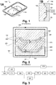
- the Figure 1A the prior art schematically represents a piece (100) thin mass produced by injection.
- this piece is a hood of electronic equipment.
- said room is made of a polymer loaded with a reinforcement in the form of fibers or balls.
- Such a part (100) generally comprises a face (110), said appearance, smooth or with an appearance texture, which face is apparent when said part is integrated into the device.
- this face comprises a decoration, which decoration is obtained by injecting the plastic into the mold while a decorative film is plated on the inner face of said mold.
- the piece (100) also comprises a face (120), said technique, which face comprises many reliefs such as ribs (121), screw wells (122), grooves (123) and so on.
- Figure 1 B the piece (100) is made by hot injection of a plastic material comprising a reinforcing filler into the closed cavity (153) of a mold (150).
- This mold thus comprises a fixed part (151) and a movable part (152).
- the injected material is fed into the cavity (153) via a conduit (161) formed in the fixed part, which conduit is connected to an injection device (160), for example a screw.
- the mold (150) must be preheated before the injection so as to obtain a uniform temperature of the surface of the cavity in contact with the injected polymer.
- the molding surfaces of the mold more particularly the molding surface located on the fixed part of said mold, are for example heated by heaters placed in grooves or bores under said molding surfaces. These arrangements are difficult to achieve on large molds and mechanically weaken the molding surfaces. Heating being conducted by conduction within the mold parts itself, a large volume of material is heated which involves a high energy expenditure and makes it difficult to obtain a high heating rate.
- the mold surfaces on either side of the cavity can be heated by induction.
- the two parts (151, 152) of the mold consist of an electrically conductive and ferromagnetic material, for example a steel comprising a large part of ferritic phase.
- each of these two parts is enclosed in a carcass (251, 252) made of a non-magnetic conductive material, such as copper (Cu), with the exception of the so-called molding surfaces (261, 262) delimiting the cavity of the mold.
- This core is electrically isolated from the two parts (151, 152) of the mold.
- the core (270) comprises surfaces (271, 272) separated at a small distance from the molding surfaces (261, 262) of the two mold parts, thus delimiting two air gaps (e 1 , e 2 ) which are insulating with said molding surfaces .
- induced currents circulate on the faces (261, 271, 262, 272) of the core and the molding surfaces facing each other, on the one hand and on the other side.
- this preheating method allows the induction molding surfaces to be heated rapidly by concentrating the heating on these surfaces when the core (270) is interposed therebetween, the mold being open.
- the core is removed, the mold (150) is closed by bringing the two parts (151, 152) together, the material in the liquid state or pasty is then injected into the molding cavity by one or more conduits (not shown).
- the preheating temperature is controlled by the electric power delivered in the induction circuit and by the heating time.
- This temperature is chosen just sufficient to allow easy flow of the injected material throughout the cavity, the heat of said material is then removed by the mass of the mold, which advantageously comprises a cooling circuit, for example by means of the circulation of a fluid in cooling ducts (281, 282) formed in each of the mold parts and extending therethrough in close proximity to the molding surfaces.
- a fluid in cooling ducts (281, 282) formed in each of the mold parts and extending therethrough in close proximity to the molding surfaces.
- this method of the prior art is effective for preheating the molding surface of the aspect face of the part, it is however not suitable for preheating the molding surface of the technical face.
- the many reliefs and technical arrangements that this face includes, such as drawers or slides do not allow to easily obtain a constant air gap between the core and the corresponding molding surface, but moreover, these form accidents disrupt the circulation of induced currents, producing local overheating see phenomena of electric arcs.
- the document AT504784 describes a method and a device for preheating a mold adapted to a plastic injection molding process, comprising a device for preheating by thermal radiation of one of the molding faces of this mold.
- this molding surface is constituted by the face of a thin piece spaced from the mold body when said mold is in the open position.
- this embodiment is complex and can not be adapted to the molding surface corresponding to the technical face of the piece.
- the document DE 10 2008 060496 discloses a method and a preheating device comprising transferring a portion of the mold comprising the molding surface to the outside of said mold for preheating thereof.
- the method which is the subject of the invention makes it possible to heat the core outside the mold, and to concentrate the heating on the molding surface, without the difficulties related to the shape of said molding surface which, according to this method, is heated. by thermal transfer.
- the induction heating of the core being separated from the molding zone, said molding zone is less congested and easier to integrate in an injection press compared to the solutions of the prior art.
- the invention can be implemented according to the advantageous embodiments described below, which can be considered individually or in any technically operative combination.
- step c) is carried out by a transfer operated mainly by thermal conduction.
- This embodiment allows rapid heat transfer, and core heating at a reduced temperature, but requires contact between the molding surface and the core.
- step a) comprises heating the core at a temperature of between 700 ° C. and 1200 ° C. and step c) is carried out by a thermal transfer mainly by radiation.
- This embodiment is more particularly suitable for heating a complex molding surface comprising numerous reliefs. The use of induction heating of the core outside the mold, allows to wear it at high temperature to obtain a fast and contactless preheating of the molding surface.
- step a) is carried out under an inert gaseous atmosphere.
- the surfaces of the core are preserved from oxidation at high temperature during the heating phase which improves the longevity of said core.
- step a) is carried out by placing the core between two electrically conductive heat shields, electrically insulated from each other and from the core, the assembly being placed inside the coil.
- the core is heated more quickly and the mold and its technical environment are protected from heat radiation of the core carried at high temperature during the heating phase of this core.
- the purged cooling channel acts as a thermally insulating barrier between the molding surface and the rest of the mold.
- the second molding surface is also heated by heat transfer during step c).
- the preheating of the two molding surfaces makes it possible to promote the uniform flow of the molded material between the molding surfaces and avoids the installation of residual stresses in the part produced by the method which is the subject of the invention.
- This variant of the method of the invention requires that the mold is also provided with an induction circuit.
- This variant embodiment is particularly, but not exclusively, adapted to the case of a molding comprising a decorative film plated on the second molding surface and makes it possible to preheat this second molding surface without degrading, by burning, said film.
- the intermediate piece is constituted by the core and step f) is carried out at the same time as step c) while means perform electrical conduction.
- step c) the intermediate piece is constituted by the core and step f) is carried out at the same time as step c) while means perform electrical conduction.
- the core and the first molding surface preheated by thermal transfer.
- the two molding surfaces of the mold are brought to the appropriate preheating temperature, the first molding surface being only by heat transfer and the second molding surface mainly by induction.
- the core consists of a block of graphite.
- This material electrically conductive, can be heated by induction at high temperature and has an emissivity coefficient close to 1 favoring, radiation heat transfer.
- the core consists of a ferromagnetic metallic material whose surface opposite the first molding surface during preheating comprises a coating whose emissivity is greater than 0.9.
- This embodiment allows to obtain a faster heating of the core while maintaining a high emissivity of the surface thereof to promote radiation heat transfer.
- the coating of the core according to this second variant of the device according to the invention consists of amorphous carbon. This coating is particularly resistant to oxidation.
- the core is hollow.
- the mass of said core is reduced which accelerates its heating and facilitates its handling.
- the transfer means of the device which is the subject of the invention comprise a robot, said robot further comprising means for demolding the part made in the cavity of the mold.
- the same transfer device is used to unmold the workpiece and to insert the core between the mold parts which reduces the size of the device and improve the productivity of the molding by combining the tasks during a single kinematic of said robot.
- the core is rapidly heated by induction by creating two air gaps and the environment is protected from the radiation of the nucleus by the screens.
- the screens are hollow. So these are easier to handle and the device is more compact.
- the screens comprise an internal cooling circuit for the circulation of a coolant.
- the device can be used at high speed without risk of degradation of the screens due to their overheating by their exposure to the radiation of the nucleus.
- the invention also relates to a device for the injection molding of a product in the liquid or pasty state in the cavity of a mold comprising two parts movable relative to each other and delimiting between them a closed cavity contained between two molding surfaces, which device comprises a preheating device according to any one of the preceding embodiments.
- the molding surface preheated mainly by thermal radiation comprises a coating whose emissivity is greater than 0.9.
- the radiation heat transfer between this molding surface and the core is improved.
- the preheating method which is the subject of the invention is implemented in an injection molding process.
- a first step (310) called opening the mold is open.
- the part produced is demolded and evacuated.
- the core is heated by induction.
- an insertion step (320) the core is introduced hot between the two open parts of the mold.
- the mold parts are brought closer to one another so as to grip the core during a preheating step (330).
- this preheating step at least one of the molding surfaces of the mold, which is in contact with the core or in the vicinity thereof is heated by heat transfer. This thermal transfer is achieved by conduction, convection or radiation according to the embodiment of the device object of the invention.
- the method comprises a step (335) of induction heating of one of the molding surface, carried out while the core has been introduced into the mold.
- At least one of the molding surfaces of the mold is heated by heat transfer in conduction, convection or radiation, the molding surface corresponding to the production of the appearance face of the mold. the molded part being heated by heat transfer or induction.
- the mold When the molding surfaces of the mold have reached a suitable temperature, the mold is opened and the core is renamed during a removal step (340). Then, the mold is closed (350) under pressure so as to form a sealed cavity between the molding surfaces of said mold. The material constituting the part is injected into the mold during an injection step (360), which injection step is followed by a cooling step. Then, the mold is again open (310) to perform the demolding (315) of the piece.
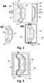
- the mold comprises a fixed part (452) which, according to this example, comprises a molding surface (462) corresponding to the molding of the appearance face of the final piece, and a moving part (451) whose molding surface (461) corresponds to the molding of the technical face of the final piece.
- the movable portion (451) is slidably connected (411) relative to the fixed portion (452) of the mold so as to allow the opening and closing of the cavity delimited by the molding surfaces (461, 462) of the two parts (451, 452). ) of the mold.
- a preheating core (470) is connected to means (412), called transfer means, for moving said core (470) between a position, Figure 4A wherein the core is between the two mold parts (451, 452) and a position, Figure 4B , or the core is separated from the mold, and wherein said core (470) can be heated to a predetermined temperature, in a so-called heating zone.
- these transfer means are constituted by a robot or a manipulator, symbolized, Figure 4A by a sliding pivot connection which allows the core (470) to be placed between the two mold parts (451, 452) by at least 90 ° rotation and by a substantially perpendicular translational movement at the mold closing plane, bringing said core (470) closer to or away from one or other of the molding surfaces (461, 462).
- the manipulator (412) comprises means (not shown) for demolding the part made during the molding operation.
- the same manipulator is used in a cycle comprising, open mold, the demolding of the piece which remains attached to the technical molding face (461), this demolding being carried out by a translational movement substantially perpendicular to the joint plane of the mold, and then evacuating the part by a rotational movement about this direction, while the core is heated in the heating zone.
- the manipulator realizes then taking the hot core and introducing it between the two parts (451,452) of the mold.
- the skilled person adapts this device according to the kinematics and the bulk of the mold and the part produced.
- the heating zone comprises an induction circuit comprising an inductor (430) consisting of two half-turns (431, 432) connected by pins (435) and which, once connected, surround the nucleus (470).
- the core is made of a material or an assembly of materials, so that said core can be rapidly heated by induction. As the core (470) is not subjected to high mechanical stresses, a wide choice of materials or material assembly is possible.
- the core (470) is made of graphite. This material can be heated inductively to a very high temperature, above 1000 ° C, and has an emissivity close to 1, producing a high thermal radiation.
- the core comprises a substrate (471) made of a ferromagnetic material, which accelerates its induction heating.
- said substrate comprises on all or part of its outer surfaces a coating (472), constituted for example by amorphous carbon, making it possible to increase the emissivity of these surfaces.
- the substrate is chosen so as to have a high Curie temperature greater than 700 ° C.
- alloys based on iron (Fe) and cobalt (Co), or based on iron (Fe) and silicon (Si) achieve such a Curie temperature.
- the high cost of these materials is offset by reduced dimensions of the core (470).
- the latter which does not support mechanical stresses, is, according to exemplary embodiments, constituted of a simple coated formed sheet or a hollow body, which also makes it easier to handle by the manipulator (412) and reduces the heating time.
- the frequency of the alternating current flowing in the inductor (430) is in the range of 10 kHz to 100 kHz and can be adapted according to the nature of the material constituting the core (470).
- the core (470) After being brought to the desired temperature, the core (470) is transferred between the two parts (451,452) of the mold. According to a first exemplary embodiment, the core (470) thus heated is brought into contact with one of the molding surfaces (461) which is then heated by conduction. According to another embodiment, said molding surface (461) is heated without contact by radiation and convection.
- the core (470) is made of graphite, its emissivity coefficient is greater than 0.9 and a large part of the thermal energy absorbed during the heating phase of the core is re-radiated.
- the core (470) is preferentially heated to high temperature, for example, at 1000 ° C.
- the heating zone is advantageously confined under a protective atmosphere in an inert gas during the heating of the core.
- the heat flux emitted towards this surface by radiation reaches values of the order of 150 ⁇ 10 3 Wm -2 .
- Such heat flow allows rapid heating of the molding surface, without contact therewith, and is effective even if said surface comprises many reliefs, such as the molding surface (461) of the technical face of the molded part.
- it is advantageously coated with a coating whose emissivity is close to 1. This effect is obtained by way of non-limiting examples.
- Figure 4A advantageously, one or both of the parts of the mold (452) comprise channels (481, 482) for the circulation of a coolant.
- the fixed part of the mold (452) corresponding to the embodiment of the aspect face of the part, comprises channels (482) for heating this part and channels (481), close the molding surface (462) for cooling the cavity.
- the movable part (451) also has cooling channels near the corresponding molding surface (461).
- said cooling channels (481) are purged before heating by thermal transfer of the molding surface (461,462) considered so as to limit heat transfer between said molding surface and the rest of the mold.
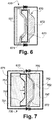
- the core (470) is placed between two screens (551, 552) made of an electrically conductive but non-ferromagnetic material, for example copper.
- the core (470) is electrically isolated from these two screens so as to create air gaps between the core surfaces and the surfaces of the screens (551, 552) facing each other.
- the core (470) is clamped in an electrically conductive but non-ferromagnetic carcass (571), for example made of copper, outside the zones (561, 562) to be heated.
- the surface of said screens (551, 552) is preferably polished so that it reflects the thermal radiation of the core (470).
- said screens are further cooled, for example by means of the circulation of a coolant, so that they are protected from excessive heating by convection because of their proximity to the core (470) worn at high temperature.
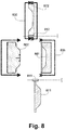
- the core (670) is constituted by an assembly comprising two materials.
- a first block (672) consists of an electrically conductive and non-ferromagnetic material, for example a copper or aluminum alloy.
- This block (672) encloses a second block (671) intended to be heated at high temperature by induction.
- This second block (671) is, by way of nonlimiting example, made of graphite or a high-Curie temperature ferromagnetic steel optionally having an emissivity coating close to 1.
- the second block (671 ) is thermally insulated from the first block (672) by a layer (673) made of thermally insulative but electrically conductive and high temperature resistant material.
- this thermally insulating layer consists of a silicon and aluminum oxynitride (SiAlON) ceramic.
- said thermally insulating layer (673) is itself composite.
- this composite core (670) is placed in an induction circuit opposite an electrically conductive screen (551), the surface of the second block (671) is rapidly raised to high temperature while the first block (672) constituting said core is little heated.
- such a composite core (670) is, according to an exemplary embodiment, used for combined heating by thermal transfer by conduction, convection or radiation of one of the molding surfaces of the mold, preferably the molding surface (761) corresponding to the face technique of the part produced, while the other molding surface (762) of said mold, corresponding to the surface of appearance, is heated by induction.
- Each part of the mold (751, 752) consists, for example, of a ferromagnetic steel and is enclosed in a carcass (791, 792) made of an electrically conductive material, for example copper.
- the first block (672) of the core is electrically isolated, for example by means of shims (770) insulating, the mold part (752) having the molding surface (762) corresponding to the face of aspect of the part so as to form an air gap between the molding surface and the first block (672) of the core (670).
- the second block (671) of the core which has previously been heated by induction, is placed in contact with or near the molding surface (761) corresponding to the technical face of the part, ensuring the electrical continuity between this molding surface (761). ) and the first block (672) of the core (670).
- the assembly being placed inside the turns of an induction circuit (730), when said circuit is powered by a high frequency alternating current, the molding surface (762) facing the first block (672) of the core (670) is induction heated, while the molding surface (761) corresponding to the technical face of the workpiece is heated by heat transfer between this molding surface and the second block (671) of the core.
- This embodiment is more particularly adapted to the case where a decorative film is placed on the molding surface (762) corresponding to the appearance face of the part before the injection and before preheating. Indeed a heating of this molding surface by heat transfer would then burn this decorative film.
- the core consists of two separate parts (871, 872) assembled at the time of their introduction between the two parts of the mold.
- a first portion of said core is heated by induction in an induction circuit (830) sepraré the mold, prior to the introduction of said first part of the core between the two mold parts by a first manipulator (812).
- this first portion (872) of the core is placed in contact with the molding surface (862) corresponding to the technical face of the part in order to achieve a heating of this surface by conduction.
- the second portion (871) of the core is made of an electrically conductive but non-ferromagnetic material such as a copper or aluminum alloy.
- This second part (871) of the core is placed opposite the molding surface (861) corresponding to the aspect face of the part, electrically isolated from the molding surface and separated therefrom by an air gap, while means (not shown) provide electrical continuity between the molding surface (862) corresponding to the technical face of the workpiece and the second portion (871) of the core.
- the assembly being placed inside the turns of an induction circuit (835) enclosing the mold, the molding surface (861) corresponding to the aspect face of the part is thus heated by induction.
- part of the means of the device object of the invention can be shared by several molds, only the core to be adapted to the shape of the part, which core is advantageously made of an easily machinable material.
Landscapes
- Engineering & Computer Science (AREA)
- Mechanical Engineering (AREA)
- Health & Medical Sciences (AREA)
- Physics & Mathematics (AREA)
- Manufacturing & Machinery (AREA)
- Toxicology (AREA)
- Thermal Sciences (AREA)
- Electromagnetism (AREA)
- Oral & Maxillofacial Surgery (AREA)
- Moulds For Moulding Plastics Or The Like (AREA)
- Injection Moulding Of Plastics Or The Like (AREA)
- Molds, Cores, And Manufacturing Methods Thereof (AREA)
- General Induction Heating (AREA)
Applications Claiming Priority (3)
| Application Number | Priority Date | Filing Date | Title |
|---|---|---|---|
| FR1255698A FR2991902A1 (fr) | 2012-06-18 | 2012-06-18 | Procede et dispositif pour le prechauffage d'un moule notamment de moulage par injection |
| FR1350684A FR2991903B1 (fr) | 2012-06-18 | 2013-01-26 | Procede et dispositif pour le prechauffage d'un moule notamment de moulage par injection |
| PCT/EP2013/062570 WO2013189907A1 (fr) | 2012-06-18 | 2013-06-18 | Procédé et dispositif pour le préchauffage d'un moule notamment de moulage par injection |
Publications (2)
| Publication Number | Publication Date |
|---|---|
| EP2861399A1 EP2861399A1 (fr) | 2015-04-22 |
| EP2861399B1 true EP2861399B1 (fr) | 2016-12-28 |
Family
ID=48044890
Family Applications (1)
| Application Number | Title | Priority Date | Filing Date |
|---|---|---|---|
| EP13732402.6A Active EP2861399B1 (fr) | 2012-06-18 | 2013-06-18 | Procédé et dispositif pour le préchauffage d'un moule notamment de moulage par injection |
Country Status (14)
| Country | Link |
|---|---|
| US (1) | US9862132B2 (enExample) |
| EP (1) | EP2861399B1 (enExample) |
| JP (1) | JP6359010B2 (enExample) |
| KR (1) | KR102149867B1 (enExample) |
| CN (1) | CN104507654B (enExample) |
| BR (1) | BR112014031836B1 (enExample) |
| CA (1) | CA2875233C (enExample) |
| ES (1) | ES2623810T3 (enExample) |
| FR (2) | FR2991902A1 (enExample) |
| IN (1) | IN2014DN10744A (enExample) |
| MX (1) | MX370917B (enExample) |
| RU (1) | RU2630119C2 (enExample) |
| TW (1) | TWI617414B (enExample) |
| WO (1) | WO2013189907A1 (enExample) |
Cited By (1)
| Publication number | Priority date | Publication date | Assignee | Title |
|---|---|---|---|---|
| US11390001B2 (en) | 2016-10-19 | 2022-07-19 | Roctool | Method and device for consolidating a textile preform and overmoulding |
Families Citing this family (23)
| Publication number | Priority date | Publication date | Assignee | Title |
|---|---|---|---|---|
| WO1992017693A1 (en) | 1991-04-01 | 1992-10-15 | Caterpillar Inc. | Dual compression and dual expansion internal combustion engine and method therefor |
| US20190118442A9 (en) * | 2010-04-20 | 2019-04-25 | Honda Motor Co., Ltd. | Conforming cooling method and mold |
| ES2769450T3 (es) * | 2012-06-19 | 2020-06-25 | Roctool | Molde para calentamiento y enfriamiento rápidos |
| FR3034093B1 (fr) * | 2015-03-24 | 2021-01-29 | Roctool | Dispositif et procede pour le formage du verre |
| TWI744228B (zh) * | 2016-03-25 | 2021-11-01 | 法商洛克杜爾公司 | 用於玻璃成型的設備及方法 |
| FR3050390B1 (fr) * | 2016-04-26 | 2020-01-24 | Roctool | Procede et dispositif pour le moulage en coquille d’un alliage metallique |
| FR3051136A1 (fr) | 2016-05-10 | 2017-11-17 | Roctool | Procede et dispositif pour le chauffage d’un moule |
| CN106626157A (zh) * | 2016-11-23 | 2017-05-10 | 惠州市锦恒工业模具设计合伙企业(普通合伙) | 一种电视机外壳模具 |
| US11225047B2 (en) | 2017-03-15 | 2022-01-18 | International Automotive Components Group North America, Inc. | Skin-foam-substrate structure via induction heating |
| US10792842B2 (en) | 2017-10-24 | 2020-10-06 | The Boeing Company | Induction molding for parts having thermoplastic portions |
| FR3072768B1 (fr) * | 2017-10-25 | 2020-01-24 | Roctool | Procede et dispositif de moulage notamment d’un verre metallique |
| US11008453B2 (en) | 2018-01-16 | 2021-05-18 | Arkema France | Polymeric composite articles comprising the heterogeneous surface/bulk distribution of discrete phase |
| CN108601128B (zh) * | 2018-04-19 | 2024-05-24 | 丰泽智能装备股份有限公司 | 电磁加热模具 |
| CN109014117B (zh) * | 2018-07-17 | 2020-02-11 | 安徽思源三轻智能制造有限公司 | 一种用于液态模锻生产的模具预热装置 |
| US11065498B2 (en) * | 2019-05-01 | 2021-07-20 | ViPR PRO, LLC | Tubular exercise device |
| US11338489B2 (en) | 2019-08-07 | 2022-05-24 | Ford Global Technologies, Llc | Method to temper the surface hardness of acrylic or other plastic automotive appliques |
| IT201900021714A1 (it) * | 2019-11-20 | 2021-05-20 | Form S R L | Stampo per pressocolata e relativo procedimento di pressocolata |
| CN112355271B (zh) * | 2020-10-30 | 2022-05-27 | 中际通达水处理装备研究院(江苏)有限公司 | 一种用于波纹钢板模具压铸过程中预热的加热装置 |
| CN112935201A (zh) * | 2021-01-27 | 2021-06-11 | 广西南宁市高创机械技术有限公司 | 一种铸造模具内表面易脱模处理方法 |
| HUE068611T2 (hu) | 2021-07-07 | 2025-01-28 | Incoe Corp | Fûtõ berendezés |
| CN114309532B (zh) * | 2021-11-26 | 2024-04-26 | 芜湖禾田汽车工业有限公司 | 一种铝合金减震塔压铸模具 |
| CN115366218B (zh) * | 2022-09-16 | 2023-03-28 | 东北农业大学 | 利用可调节厚度且便于脱模的模具制备可降解花盆的方法 |
| DE102022130109B3 (de) | 2022-11-15 | 2024-05-02 | Dr. Ing. H.C. F. Porsche Aktiengesellschaft | Verfahren und Einrichtung zum Herstellen einer elektrischen Maschine mit Kunststoffdichtungen an den Stirnseiten des Statorblechpakets |
Family Cites Families (22)
| Publication number | Priority date | Publication date | Assignee | Title |
|---|---|---|---|---|
| US4439492A (en) * | 1980-08-11 | 1984-03-27 | Asahi-Dow Limited | Injection molded articles with improved surface characteristics |
| DE4308008A1 (de) * | 1993-03-13 | 1994-09-15 | Jung Artur Prof Dipl Ing | Dynamische Formtemperierung beim Spritzgießen |
| JP3632257B2 (ja) * | 1995-10-09 | 2005-03-23 | 豊田合成株式会社 | 金型の加熱装置、加熱冷却装置及びその方法 |
| JPH1119986A (ja) * | 1997-07-07 | 1999-01-26 | Sekisui Chem Co Ltd | 射出成形品の製造方法 |
| EP1412152A2 (en) * | 2001-07-31 | 2004-04-28 | SK Chemicals Co., Ltd. | Method for molding a product and a mold used therein |
| JP2003342752A (ja) * | 2002-05-21 | 2003-12-03 | Mitsubishi Heavy Ind Ltd | 真空用耐熱耐蝕コーティング部材、同部材を用いた部品を有する真空装置及び同コーティング方法 |
| JP3932985B2 (ja) * | 2002-06-04 | 2007-06-20 | 富士電機デバイステクノロジー株式会社 | プレス成形装置およびプレス成形方法 |
| KR20040026865A (ko) * | 2002-09-26 | 2004-04-01 | 강명호 | 전열을 이용한 금형 가열방법 및 그 장치 및 그로부터제조된 물품 |
| WO2005051571A1 (en) * | 2003-11-26 | 2005-06-09 | Price, James, Cairns | Casting of metal artefacts |
| FR2867939B1 (fr) * | 2004-03-18 | 2007-08-10 | Roctool | Procede pour chauffer des materiaux en vue de produire des objets et dispositif mettant en oeuvre de procede |
| FR2890588B1 (fr) * | 2005-09-12 | 2007-11-16 | Roctool Soc Par Actions Simpli | Dispositif de transformation de materiaux utilisant un chauffage par induction |
| CN2850885Y (zh) * | 2005-12-22 | 2006-12-27 | 佛山市顺德区汉达精密电子科技有限公司 | 用于加热模具中内表面的装置 |
| JP2008110583A (ja) * | 2006-10-31 | 2008-05-15 | Alps Electric Co Ltd | 射出成形装置および射出成形方法 |
| JP4567011B2 (ja) * | 2007-02-15 | 2010-10-20 | 株式会社日本製鋼所 | 射出成形方法および射出成形装置 |
| AT504784B1 (de) | 2007-06-01 | 2008-08-15 | Engel Austria Gmbh | Formwerkzeug |
| AT506097B1 (de) * | 2007-12-14 | 2010-03-15 | Engel Austria Gmbh | Heizvorrichtung für ein formwerkzeug |
| AT506491B1 (de) * | 2008-01-28 | 2010-05-15 | Engel Austria Gmbh | Werkzeugeinsatz mit integrierter heizvorrichtung |
| JP2009202348A (ja) * | 2008-02-26 | 2009-09-10 | Panasonic Corp | 金型装置 |
| TWI355326B (en) * | 2008-09-30 | 2012-01-01 | Mitac Prec Technology Kunshan | Rapid extrusion molding system |
| FR2937270B1 (fr) * | 2008-10-20 | 2010-11-26 | Roctool | Dispositif de transformation de materiaux utilisant un chauffage par induction permettant un prechauffage du dispositif |
| JP5277401B2 (ja) * | 2009-06-15 | 2013-08-28 | 富士電機株式会社 | 金型の加熱方法および装置 |
| TW201119835A (en) * | 2009-12-10 | 2011-06-16 | Quanta Comp Inc | Pre-heat apparatus, injection molding with the same, and method of pre-heating injection molding |
-
2012
- 2012-06-18 FR FR1255698A patent/FR2991902A1/fr active Pending
-
2013
- 2013-01-26 FR FR1350684A patent/FR2991903B1/fr not_active Expired - Fee Related
- 2013-06-18 CA CA2875233A patent/CA2875233C/fr active Active
- 2013-06-18 MX MX2014015700A patent/MX370917B/es active IP Right Grant
- 2013-06-18 RU RU2015101238A patent/RU2630119C2/ru active
- 2013-06-18 JP JP2015517719A patent/JP6359010B2/ja active Active
- 2013-06-18 BR BR112014031836-0A patent/BR112014031836B1/pt not_active IP Right Cessation
- 2013-06-18 WO PCT/EP2013/062570 patent/WO2013189907A1/fr not_active Ceased
- 2013-06-18 ES ES13732402.6T patent/ES2623810T3/es active Active
- 2013-06-18 US US14/408,672 patent/US9862132B2/en active Active
- 2013-06-18 TW TW102121454A patent/TWI617414B/zh active
- 2013-06-18 KR KR1020147036193A patent/KR102149867B1/ko active Active
- 2013-06-18 IN IN10744DEN2014 patent/IN2014DN10744A/en unknown
- 2013-06-18 CN CN201380031892.5A patent/CN104507654B/zh active Active
- 2013-06-18 EP EP13732402.6A patent/EP2861399B1/fr active Active
Cited By (1)
| Publication number | Priority date | Publication date | Assignee | Title |
|---|---|---|---|---|
| US11390001B2 (en) | 2016-10-19 | 2022-07-19 | Roctool | Method and device for consolidating a textile preform and overmoulding |
Also Published As
| Publication number | Publication date |
|---|---|
| MX2014015700A (es) | 2015-11-16 |
| EP2861399A1 (fr) | 2015-04-22 |
| CN104507654B (zh) | 2017-05-17 |
| CN104507654A (zh) | 2015-04-08 |
| ES2623810T3 (es) | 2017-07-12 |
| US20150151471A1 (en) | 2015-06-04 |
| FR2991902A1 (fr) | 2013-12-20 |
| BR112014031836A2 (pt) | 2017-06-27 |
| KR102149867B1 (ko) | 2020-08-31 |
| JP2015525157A (ja) | 2015-09-03 |
| FR2991903B1 (fr) | 2014-08-22 |
| RU2630119C2 (ru) | 2017-09-05 |
| CA2875233A1 (fr) | 2013-12-27 |
| TW201412487A (zh) | 2014-04-01 |
| TWI617414B (zh) | 2018-03-11 |
| RU2015101238A (ru) | 2016-08-10 |
| KR20150020598A (ko) | 2015-02-26 |
| FR2991903A1 (fr) | 2013-12-20 |
| US9862132B2 (en) | 2018-01-09 |
| MX370917B (es) | 2020-01-09 |
| CA2875233C (fr) | 2020-03-24 |
| BR112014031836B1 (pt) | 2021-08-24 |
| IN2014DN10744A (enExample) | 2015-09-04 |
| JP6359010B2 (ja) | 2018-07-18 |
| WO2013189907A1 (fr) | 2013-12-27 |
Similar Documents
| Publication | Publication Date | Title |
|---|---|---|
| EP2861399B1 (fr) | Procédé et dispositif pour le préchauffage d'un moule notamment de moulage par injection | |
| EP1728411B1 (fr) | Procede pour chauffer des materiaux en vue de produire des objets et dispositif mettant en oeuvre ce procede | |
| EP1924415B1 (fr) | Dispositif de transformation de materiaux utilisant un chauffage par induction | |
| CA2718485C (fr) | Dispositif de transformation de materiaux utilisant un chauffage par induction et des moyens de compactage deformables | |
| EP2349667B1 (fr) | Dispositif de transformation de materiaux utilisant un chauffage par induction permettant un prechauffage du dispositif | |
| EP1894442B1 (fr) | Dispositif de chauffage par induction et procede de fabrication de pieces a l'aide d'un tel dispositif | |
| CA2945246A1 (fr) | Dispositif pour le chauffage d'un moule | |
| WO2016151127A1 (fr) | Dispositif et procédé pour le formage du verre | |
| EP3529028B1 (fr) | Procédé et dispositif pour la consolidation d'une préforme textile et surmoulage | |
| WO2008142337A2 (fr) | Procede et dispositif de chauffage de pieces tubulaires ou pleines par induction | |
| WO2019081687A1 (fr) | Procédé et dispositif de moulage notamment d'un verre métallique |
Legal Events
| Date | Code | Title | Description |
|---|---|---|---|
| PUAI | Public reference made under article 153(3) epc to a published international application that has entered the european phase |
Free format text: ORIGINAL CODE: 0009012 |
|
| 17P | Request for examination filed |
Effective date: 20150119 |
|
| AK | Designated contracting states |
Kind code of ref document: A1 Designated state(s): AL AT BE BG CH CY CZ DE DK EE ES FI FR GB GR HR HU IE IS IT LI LT LU LV MC MK MT NL NO PL PT RO RS SE SI SK SM TR |
|
| AX | Request for extension of the european patent |
Extension state: BA ME |
|
| DAX | Request for extension of the european patent (deleted) | ||
| GRAP | Despatch of communication of intention to grant a patent |
Free format text: ORIGINAL CODE: EPIDOSNIGR1 |
|
| INTG | Intention to grant announced |
Effective date: 20160705 |
|
| GRAS | Grant fee paid |
Free format text: ORIGINAL CODE: EPIDOSNIGR3 |
|
| GRAA | (expected) grant |
Free format text: ORIGINAL CODE: 0009210 |
|
| AK | Designated contracting states |
Kind code of ref document: B1 Designated state(s): AL AT BE BG CH CY CZ DE DK EE ES FI FR GB GR HR HU IE IS IT LI LT LU LV MC MK MT NL NO PL PT RO RS SE SI SK SM TR |
|
| REG | Reference to a national code |
Ref country code: GB Ref legal event code: FG4D Free format text: NOT ENGLISH |
|
| REG | Reference to a national code |
Ref country code: CH Ref legal event code: EP |
|
| REG | Reference to a national code |
Ref country code: AT Ref legal event code: REF Ref document number: 856898 Country of ref document: AT Kind code of ref document: T Effective date: 20170115 |
|
| REG | Reference to a national code |
Ref country code: IE Ref legal event code: FG4D Free format text: LANGUAGE OF EP DOCUMENT: FRENCH |
|
| REG | Reference to a national code |
Ref country code: DE Ref legal event code: R096 Ref document number: 602013015882 Country of ref document: DE |
|
| PG25 | Lapsed in a contracting state [announced via postgrant information from national office to epo] |
Ref country code: LV Free format text: LAPSE BECAUSE OF FAILURE TO SUBMIT A TRANSLATION OF THE DESCRIPTION OR TO PAY THE FEE WITHIN THE PRESCRIBED TIME-LIMIT Effective date: 20161228 |
|
| REG | Reference to a national code |
Ref country code: LT Ref legal event code: MG4D |
|
| PG25 | Lapsed in a contracting state [announced via postgrant information from national office to epo] |
Ref country code: SE Free format text: LAPSE BECAUSE OF FAILURE TO SUBMIT A TRANSLATION OF THE DESCRIPTION OR TO PAY THE FEE WITHIN THE PRESCRIBED TIME-LIMIT Effective date: 20161228 Ref country code: NO Free format text: LAPSE BECAUSE OF FAILURE TO SUBMIT A TRANSLATION OF THE DESCRIPTION OR TO PAY THE FEE WITHIN THE PRESCRIBED TIME-LIMIT Effective date: 20170328 Ref country code: LT Free format text: LAPSE BECAUSE OF FAILURE TO SUBMIT A TRANSLATION OF THE DESCRIPTION OR TO PAY THE FEE WITHIN THE PRESCRIBED TIME-LIMIT Effective date: 20161228 Ref country code: GR Free format text: LAPSE BECAUSE OF FAILURE TO SUBMIT A TRANSLATION OF THE DESCRIPTION OR TO PAY THE FEE WITHIN THE PRESCRIBED TIME-LIMIT Effective date: 20170329 |
|
| REG | Reference to a national code |
Ref country code: NL Ref legal event code: MP Effective date: 20161228 |
|
| REG | Reference to a national code |
Ref country code: AT Ref legal event code: MK05 Ref document number: 856898 Country of ref document: AT Kind code of ref document: T Effective date: 20161228 |
|
| PG25 | Lapsed in a contracting state [announced via postgrant information from national office to epo] |
Ref country code: FI Free format text: LAPSE BECAUSE OF FAILURE TO SUBMIT A TRANSLATION OF THE DESCRIPTION OR TO PAY THE FEE WITHIN THE PRESCRIBED TIME-LIMIT Effective date: 20161228 Ref country code: HR Free format text: LAPSE BECAUSE OF FAILURE TO SUBMIT A TRANSLATION OF THE DESCRIPTION OR TO PAY THE FEE WITHIN THE PRESCRIBED TIME-LIMIT Effective date: 20161228 Ref country code: RS Free format text: LAPSE BECAUSE OF FAILURE TO SUBMIT A TRANSLATION OF THE DESCRIPTION OR TO PAY THE FEE WITHIN THE PRESCRIBED TIME-LIMIT Effective date: 20161228 |
|
| PG25 | Lapsed in a contracting state [announced via postgrant information from national office to epo] |
Ref country code: NL Free format text: LAPSE BECAUSE OF FAILURE TO SUBMIT A TRANSLATION OF THE DESCRIPTION OR TO PAY THE FEE WITHIN THE PRESCRIBED TIME-LIMIT Effective date: 20161228 |
|
| REG | Reference to a national code |
Ref country code: FR Ref legal event code: PLFP Year of fee payment: 5 |
|
| REG | Reference to a national code |
Ref country code: ES Ref legal event code: FG2A Ref document number: 2623810 Country of ref document: ES Kind code of ref document: T3 Effective date: 20170712 |
|
| PG25 | Lapsed in a contracting state [announced via postgrant information from national office to epo] |
Ref country code: CZ Free format text: LAPSE BECAUSE OF FAILURE TO SUBMIT A TRANSLATION OF THE DESCRIPTION OR TO PAY THE FEE WITHIN THE PRESCRIBED TIME-LIMIT Effective date: 20161228 Ref country code: RO Free format text: LAPSE BECAUSE OF FAILURE TO SUBMIT A TRANSLATION OF THE DESCRIPTION OR TO PAY THE FEE WITHIN THE PRESCRIBED TIME-LIMIT Effective date: 20161228 Ref country code: EE Free format text: LAPSE BECAUSE OF FAILURE TO SUBMIT A TRANSLATION OF THE DESCRIPTION OR TO PAY THE FEE WITHIN THE PRESCRIBED TIME-LIMIT Effective date: 20161228 Ref country code: IS Free format text: LAPSE BECAUSE OF FAILURE TO SUBMIT A TRANSLATION OF THE DESCRIPTION OR TO PAY THE FEE WITHIN THE PRESCRIBED TIME-LIMIT Effective date: 20170428 Ref country code: SK Free format text: LAPSE BECAUSE OF FAILURE TO SUBMIT A TRANSLATION OF THE DESCRIPTION OR TO PAY THE FEE WITHIN THE PRESCRIBED TIME-LIMIT Effective date: 20161228 |
|
| PG25 | Lapsed in a contracting state [announced via postgrant information from national office to epo] |
Ref country code: BG Free format text: LAPSE BECAUSE OF FAILURE TO SUBMIT A TRANSLATION OF THE DESCRIPTION OR TO PAY THE FEE WITHIN THE PRESCRIBED TIME-LIMIT Effective date: 20170328 Ref country code: AT Free format text: LAPSE BECAUSE OF FAILURE TO SUBMIT A TRANSLATION OF THE DESCRIPTION OR TO PAY THE FEE WITHIN THE PRESCRIBED TIME-LIMIT Effective date: 20161228 Ref country code: PT Free format text: LAPSE BECAUSE OF FAILURE TO SUBMIT A TRANSLATION OF THE DESCRIPTION OR TO PAY THE FEE WITHIN THE PRESCRIBED TIME-LIMIT Effective date: 20170428 Ref country code: PL Free format text: LAPSE BECAUSE OF FAILURE TO SUBMIT A TRANSLATION OF THE DESCRIPTION OR TO PAY THE FEE WITHIN THE PRESCRIBED TIME-LIMIT Effective date: 20161228 Ref country code: SM Free format text: LAPSE BECAUSE OF FAILURE TO SUBMIT A TRANSLATION OF THE DESCRIPTION OR TO PAY THE FEE WITHIN THE PRESCRIBED TIME-LIMIT Effective date: 20161228 |
|
| REG | Reference to a national code |
Ref country code: DE Ref legal event code: R097 Ref document number: 602013015882 Country of ref document: DE |
|
| PLBE | No opposition filed within time limit |
Free format text: ORIGINAL CODE: 0009261 |
|
| STAA | Information on the status of an ep patent application or granted ep patent |
Free format text: STATUS: NO OPPOSITION FILED WITHIN TIME LIMIT |
|
| PG25 | Lapsed in a contracting state [announced via postgrant information from national office to epo] |
Ref country code: DK Free format text: LAPSE BECAUSE OF FAILURE TO SUBMIT A TRANSLATION OF THE DESCRIPTION OR TO PAY THE FEE WITHIN THE PRESCRIBED TIME-LIMIT Effective date: 20161228 |
|
| 26N | No opposition filed |
Effective date: 20170929 |
|
| PG25 | Lapsed in a contracting state [announced via postgrant information from national office to epo] |
Ref country code: MC Free format text: LAPSE BECAUSE OF FAILURE TO SUBMIT A TRANSLATION OF THE DESCRIPTION OR TO PAY THE FEE WITHIN THE PRESCRIBED TIME-LIMIT Effective date: 20161228 |
|
| PG25 | Lapsed in a contracting state [announced via postgrant information from national office to epo] |
Ref country code: SI Free format text: LAPSE BECAUSE OF FAILURE TO SUBMIT A TRANSLATION OF THE DESCRIPTION OR TO PAY THE FEE WITHIN THE PRESCRIBED TIME-LIMIT Effective date: 20161228 |
|
| PG25 | Lapsed in a contracting state [announced via postgrant information from national office to epo] |
Ref country code: LU Free format text: LAPSE BECAUSE OF NON-PAYMENT OF DUE FEES Effective date: 20170618 |
|
| PG25 | Lapsed in a contracting state [announced via postgrant information from national office to epo] |
Ref country code: IT Free format text: LAPSE BECAUSE OF NON-PAYMENT OF DUE FEES Effective date: 20170618 |
|
| REG | Reference to a national code |
Ref country code: FR Ref legal event code: PLFP Year of fee payment: 6 |
|
| PG25 | Lapsed in a contracting state [announced via postgrant information from national office to epo] |
Ref country code: MT Free format text: LAPSE BECAUSE OF FAILURE TO SUBMIT A TRANSLATION OF THE DESCRIPTION OR TO PAY THE FEE WITHIN THE PRESCRIBED TIME-LIMIT Effective date: 20161228 |
|
| PG25 | Lapsed in a contracting state [announced via postgrant information from national office to epo] |
Ref country code: HU Free format text: LAPSE BECAUSE OF FAILURE TO SUBMIT A TRANSLATION OF THE DESCRIPTION OR TO PAY THE FEE WITHIN THE PRESCRIBED TIME-LIMIT; INVALID AB INITIO Effective date: 20130618 |
|
| PG25 | Lapsed in a contracting state [announced via postgrant information from national office to epo] |
Ref country code: IT Free format text: LAPSE BECAUSE OF NON-PAYMENT OF DUE FEES Effective date: 20170618 |
|
| PGRI | Patent reinstated in contracting state [announced from national office to epo] |
Ref country code: IT Effective date: 20190705 |
|
| PG25 | Lapsed in a contracting state [announced via postgrant information from national office to epo] |
Ref country code: CY Free format text: LAPSE BECAUSE OF FAILURE TO SUBMIT A TRANSLATION OF THE DESCRIPTION OR TO PAY THE FEE WITHIN THE PRESCRIBED TIME-LIMIT Effective date: 20161228 |
|
| PG25 | Lapsed in a contracting state [announced via postgrant information from national office to epo] |
Ref country code: MK Free format text: LAPSE BECAUSE OF FAILURE TO SUBMIT A TRANSLATION OF THE DESCRIPTION OR TO PAY THE FEE WITHIN THE PRESCRIBED TIME-LIMIT Effective date: 20161228 |
|
| PG25 | Lapsed in a contracting state [announced via postgrant information from national office to epo] |
Ref country code: TR Free format text: LAPSE BECAUSE OF FAILURE TO SUBMIT A TRANSLATION OF THE DESCRIPTION OR TO PAY THE FEE WITHIN THE PRESCRIBED TIME-LIMIT Effective date: 20161228 |
|
| PG25 | Lapsed in a contracting state [announced via postgrant information from national office to epo] |
Ref country code: AL Free format text: LAPSE BECAUSE OF FAILURE TO SUBMIT A TRANSLATION OF THE DESCRIPTION OR TO PAY THE FEE WITHIN THE PRESCRIBED TIME-LIMIT Effective date: 20161228 |
|
| P01 | Opt-out of the competence of the unified patent court (upc) registered |
Effective date: 20230531 |
|
| PGFP | Annual fee paid to national office [announced via postgrant information from national office to epo] |
Ref country code: IE Payment date: 20230629 Year of fee payment: 11 |
|
| PGFP | Annual fee paid to national office [announced via postgrant information from national office to epo] |
Ref country code: BE Payment date: 20230629 Year of fee payment: 11 |
|
| PGFP | Annual fee paid to national office [announced via postgrant information from national office to epo] |
Ref country code: ES Payment date: 20230807 Year of fee payment: 11 Ref country code: CH Payment date: 20230705 Year of fee payment: 11 |
|
| PGFP | Annual fee paid to national office [announced via postgrant information from national office to epo] |
Ref country code: IT Payment date: 20240627 Year of fee payment: 12 |
|
| REG | Reference to a national code |
Ref country code: CH Ref legal event code: PL |
|
| PG25 | Lapsed in a contracting state [announced via postgrant information from national office to epo] |
Ref country code: IE Free format text: LAPSE BECAUSE OF NON-PAYMENT OF DUE FEES Effective date: 20240618 |
|
| PG25 | Lapsed in a contracting state [announced via postgrant information from national office to epo] |
Ref country code: CH Free format text: LAPSE BECAUSE OF NON-PAYMENT OF DUE FEES Effective date: 20240630 Ref country code: BE Free format text: LAPSE BECAUSE OF NON-PAYMENT OF DUE FEES Effective date: 20240630 |
|
| REG | Reference to a national code |
Ref country code: BE Ref legal event code: MM Effective date: 20240630 |
|
| REG | Reference to a national code |
Ref country code: ES Ref legal event code: FD2A Effective date: 20250801 |
|
| PG25 | Lapsed in a contracting state [announced via postgrant information from national office to epo] |
Ref country code: ES Free format text: LAPSE BECAUSE OF NON-PAYMENT OF DUE FEES Effective date: 20240619 |
|
| PGFP | Annual fee paid to national office [announced via postgrant information from national office to epo] |
Ref country code: DE Payment date: 20250701 Year of fee payment: 13 |
|
| PGFP | Annual fee paid to national office [announced via postgrant information from national office to epo] |
Ref country code: GB Payment date: 20250704 Year of fee payment: 13 |
|
| PGFP | Annual fee paid to national office [announced via postgrant information from national office to epo] |
Ref country code: FR Payment date: 20250701 Year of fee payment: 13 |