EP2861189B1 - Endovascular delivery system with an improved radiopaque marker scheme - Google Patents
Endovascular delivery system with an improved radiopaque marker scheme Download PDFInfo
- Publication number
- EP2861189B1 EP2861189B1 EP13733113.8A EP13733113A EP2861189B1 EP 2861189 B1 EP2861189 B1 EP 2861189B1 EP 13733113 A EP13733113 A EP 13733113A EP 2861189 B1 EP2861189 B1 EP 2861189B1
- Authority
- EP
- European Patent Office
- Prior art keywords
- markers
- prosthesis
- delivery system
- guidewire
- stent
- Prior art date
- Legal status (The legal status is an assumption and is not a legal conclusion. Google has not performed a legal analysis and makes no representation as to the accuracy of the status listed.)
- Active
Links
Images


Classifications
-
- A—HUMAN NECESSITIES
- A61—MEDICAL OR VETERINARY SCIENCE; HYGIENE
- A61F—FILTERS IMPLANTABLE INTO BLOOD VESSELS; PROSTHESES; DEVICES PROVIDING PATENCY TO, OR PREVENTING COLLAPSING OF, TUBULAR STRUCTURES OF THE BODY, e.g. STENTS; ORTHOPAEDIC, NURSING OR CONTRACEPTIVE DEVICES; FOMENTATION; TREATMENT OR PROTECTION OF EYES OR EARS; BANDAGES, DRESSINGS OR ABSORBENT PADS; FIRST-AID KITS
- A61F2/00—Filters implantable into blood vessels; Prostheses, i.e. artificial substitutes or replacements for parts of the body; Appliances for connecting them with the body; Devices providing patency to, or preventing collapsing of, tubular structures of the body, e.g. stents
- A61F2/95—Instruments specially adapted for placement or removal of stents or stent-grafts
- A61F2/962—Instruments specially adapted for placement or removal of stents or stent-grafts having an outer sleeve
- A61F2/966—Instruments specially adapted for placement or removal of stents or stent-grafts having an outer sleeve with relative longitudinal movement between outer sleeve and prosthesis, e.g. using a push rod
-
- A—HUMAN NECESSITIES
- A61—MEDICAL OR VETERINARY SCIENCE; HYGIENE
- A61F—FILTERS IMPLANTABLE INTO BLOOD VESSELS; PROSTHESES; DEVICES PROVIDING PATENCY TO, OR PREVENTING COLLAPSING OF, TUBULAR STRUCTURES OF THE BODY, e.g. STENTS; ORTHOPAEDIC, NURSING OR CONTRACEPTIVE DEVICES; FOMENTATION; TREATMENT OR PROTECTION OF EYES OR EARS; BANDAGES, DRESSINGS OR ABSORBENT PADS; FIRST-AID KITS
- A61F2/00—Filters implantable into blood vessels; Prostheses, i.e. artificial substitutes or replacements for parts of the body; Appliances for connecting them with the body; Devices providing patency to, or preventing collapsing of, tubular structures of the body, e.g. stents
- A61F2/95—Instruments specially adapted for placement or removal of stents or stent-grafts
- A61F2/9522—Means for mounting a stent or stent-graft onto or into a placement instrument
-
- A—HUMAN NECESSITIES
- A61—MEDICAL OR VETERINARY SCIENCE; HYGIENE
- A61F—FILTERS IMPLANTABLE INTO BLOOD VESSELS; PROSTHESES; DEVICES PROVIDING PATENCY TO, OR PREVENTING COLLAPSING OF, TUBULAR STRUCTURES OF THE BODY, e.g. STENTS; ORTHOPAEDIC, NURSING OR CONTRACEPTIVE DEVICES; FOMENTATION; TREATMENT OR PROTECTION OF EYES OR EARS; BANDAGES, DRESSINGS OR ABSORBENT PADS; FIRST-AID KITS
- A61F2/00—Filters implantable into blood vessels; Prostheses, i.e. artificial substitutes or replacements for parts of the body; Appliances for connecting them with the body; Devices providing patency to, or preventing collapsing of, tubular structures of the body, e.g. stents
- A61F2/95—Instruments specially adapted for placement or removal of stents or stent-grafts
- A61F2002/9505—Instruments specially adapted for placement or removal of stents or stent-grafts having retaining means other than an outer sleeve, e.g. male-female connector between stent and instrument
- A61F2002/9511—Instruments specially adapted for placement or removal of stents or stent-grafts having retaining means other than an outer sleeve, e.g. male-female connector between stent and instrument the retaining means being filaments or wires
-
- A—HUMAN NECESSITIES
- A61—MEDICAL OR VETERINARY SCIENCE; HYGIENE
- A61F—FILTERS IMPLANTABLE INTO BLOOD VESSELS; PROSTHESES; DEVICES PROVIDING PATENCY TO, OR PREVENTING COLLAPSING OF, TUBULAR STRUCTURES OF THE BODY, e.g. STENTS; ORTHOPAEDIC, NURSING OR CONTRACEPTIVE DEVICES; FOMENTATION; TREATMENT OR PROTECTION OF EYES OR EARS; BANDAGES, DRESSINGS OR ABSORBENT PADS; FIRST-AID KITS
- A61F2/00—Filters implantable into blood vessels; Prostheses, i.e. artificial substitutes or replacements for parts of the body; Appliances for connecting them with the body; Devices providing patency to, or preventing collapsing of, tubular structures of the body, e.g. stents
- A61F2/95—Instruments specially adapted for placement or removal of stents or stent-grafts
- A61F2/962—Instruments specially adapted for placement or removal of stents or stent-grafts having an outer sleeve
- A61F2/966—Instruments specially adapted for placement or removal of stents or stent-grafts having an outer sleeve with relative longitudinal movement between outer sleeve and prosthesis, e.g. using a push rod
- A61F2002/9665—Instruments specially adapted for placement or removal of stents or stent-grafts having an outer sleeve with relative longitudinal movement between outer sleeve and prosthesis, e.g. using a push rod with additional retaining means
-
- A—HUMAN NECESSITIES
- A61—MEDICAL OR VETERINARY SCIENCE; HYGIENE
- A61F—FILTERS IMPLANTABLE INTO BLOOD VESSELS; PROSTHESES; DEVICES PROVIDING PATENCY TO, OR PREVENTING COLLAPSING OF, TUBULAR STRUCTURES OF THE BODY, e.g. STENTS; ORTHOPAEDIC, NURSING OR CONTRACEPTIVE DEVICES; FOMENTATION; TREATMENT OR PROTECTION OF EYES OR EARS; BANDAGES, DRESSINGS OR ABSORBENT PADS; FIRST-AID KITS
- A61F2230/00—Geometry of prostheses classified in groups A61F2/00 - A61F2/26 or A61F2/82 or A61F9/00 or A61F11/00 or subgroups thereof
- A61F2230/0063—Three-dimensional shapes
- A61F2230/0069—Three-dimensional shapes cylindrical
-
- A—HUMAN NECESSITIES
- A61—MEDICAL OR VETERINARY SCIENCE; HYGIENE
- A61F—FILTERS IMPLANTABLE INTO BLOOD VESSELS; PROSTHESES; DEVICES PROVIDING PATENCY TO, OR PREVENTING COLLAPSING OF, TUBULAR STRUCTURES OF THE BODY, e.g. STENTS; ORTHOPAEDIC, NURSING OR CONTRACEPTIVE DEVICES; FOMENTATION; TREATMENT OR PROTECTION OF EYES OR EARS; BANDAGES, DRESSINGS OR ABSORBENT PADS; FIRST-AID KITS
- A61F2250/00—Special features of prostheses classified in groups A61F2/00 - A61F2/26 or A61F2/82 or A61F9/00 or A61F11/00 or subgroups thereof
- A61F2250/0003—Special features of prostheses classified in groups A61F2/00 - A61F2/26 or A61F2/82 or A61F9/00 or A61F11/00 or subgroups thereof having an inflatable pocket filled with fluid, e.g. liquid or gas
-
- A—HUMAN NECESSITIES
- A61—MEDICAL OR VETERINARY SCIENCE; HYGIENE
- A61F—FILTERS IMPLANTABLE INTO BLOOD VESSELS; PROSTHESES; DEVICES PROVIDING PATENCY TO, OR PREVENTING COLLAPSING OF, TUBULAR STRUCTURES OF THE BODY, e.g. STENTS; ORTHOPAEDIC, NURSING OR CONTRACEPTIVE DEVICES; FOMENTATION; TREATMENT OR PROTECTION OF EYES OR EARS; BANDAGES, DRESSINGS OR ABSORBENT PADS; FIRST-AID KITS
- A61F2250/00—Special features of prostheses classified in groups A61F2/00 - A61F2/26 or A61F2/82 or A61F9/00 or A61F11/00 or subgroups thereof
- A61F2250/0058—Additional features; Implant or prostheses properties not otherwise provided for
- A61F2250/0096—Markers and sensors for detecting a position or changes of a position of an implant, e.g. RF sensors, ultrasound markers
- A61F2250/0098—Markers and sensors for detecting a position or changes of a position of an implant, e.g. RF sensors, ultrasound markers radio-opaque, e.g. radio-opaque markers
Definitions
- the present invention is related to an endovascular delivery system for an endovascular prosthesis. More particularly, the present invention is related to an endovascular delivery system including an improved radiopaque marker system for accurate delivery of the prosthesis.
- An aneurysm is a medical condition indicated generally by an expansion and weakening of the wall of an artery of a patient. Aneurysms can develop at various sites within a patient's body. Thoracic aortic aneurysms (TAAs) or abdominal aortic aneurysms (AAAs) are manifested by an expansion and weakening of the aorta which is a serious and life threatening condition for which intervention is generally indicated.
- TAAs Thoracic aortic aneurysms
- AAAs abdominal aortic aneurysms
- Existing methods of treating aneurysms include invasive surgical procedures with graft replacement of the affected vessel or body lumen or reinforcement of the vessel with a graft.
- Surgical procedures to treat aortic aneurysms can have relatively high morbidity and mortality rates due to the risk factors inherent to surgical repair of this disease as well as long hospital stays and painful recoveries. This is especially true for surgical repair of TAAs, which is generally regarded as involving higher risk and more difficulty when compared to surgical repair of AAAs.
- An example of a surgical procedure involving repair of a AAA is described in a book titled Surgical Treatment of Aortic Aneurysms by Denton A. Cooley, M.D., published in 1986 by W.B. Saunders Company .
- endovascular repair has become a widely-used alternative therapy, most notably in treating AAAs.
- Early work in this field is exemplified by Lawrence, Jr. et al. in "Percutaneous Endovascular Graft Experimental Evaluation", Radiology ( May 1987 ) and by Mirich et al. in "Percutaneously Placed Endovascular Grafts for Aortic Aneurysms: Feasibility Study,” Radiology (March 1989 ).
- Commercially available endoprostheses for the endovascular treatment of AAAs include the AneuRx ® stent graft manufactured by Medtronic, Inc.
- a commercially available stent graft for the treatment of TAAs is the TAG TM system manufactured by W.L. Gore & Associates, Inc.
- stent graft and delivery system for passage through the various guiding catheters as well as the patient's sometimes tortuous anatomy.
- Many of the existing endovascular devices and methods for treatment of aneurysms while representing significant advancement over previous devices and methods, use systems having relatively large transverse profiles, often up to 24 French. Also, such existing systems have greater than desired lateral stiffness, which can complicate the delivery process.
- the sizing of stent grafts may be important to achieve a favorable clinical result.
- a stent graft In order to properly size a stent graft, the treating facility typically must maintain a large and expensive inventory of stent grafts in order to accommodate the varied sizes of patient vessels due to varied patient sizes and vessel morphologies. Alternatively, intervention may be delayed while awaiting custom size stent grafts to be manufactured and sent to the treating facility. As such, minimally invasive endovascular treatment of aneurysms is not available for many patients that would benefit from such a procedure and can be more difficult to carry out for those patients for whom the procedure is indicated. What have been needed are stent graft systems, delivery systems and methods that are adaptable to a wide range of patient anatomies and that can be safely and reliably deployed using a flexible low profile system.
- US20100274276A1 discloses a treatment device which treats an aneurysm in a primary vessel such as an intracranial vessel.
- the treatment device comprises an expandable sleeve having a fluid-flow-restricting patch, and a radiopaque marker disposed on the sleeve, having a defined relationship with respect to the patch.
- EP2208483A1 discloses a neurovascular stent delivery apparatus.
- the delivery apparatus includes an outer catheter, an inner shaft located coaxially within the outer catheter, and a compressed self-expanding stent comprising a plurality of closed cells mounted on the distal section of the inner shaft and preloaded within the outer catheter distal region.
- the inner shaft comprises one or more blocking members disposed in the distal section.
- a radiopaque marker on the stent allows for visualization of the stent relative a target location.
- the present invention is directed to an endovascular delivery system according to claim 1.
- the present disclosure also provides a method of delivering a prosthesis within a body lumen, which such method includes the step of providing a delivery system.
- the delivery system includes an elongate outer tubular device having an open lumen and opposed proximal and distal ends with a medial portion therein between.
- the system may also include a prosthesis holder disposed within the outer tubular device.
- the prosthesis holder may include an axial guidewire extending through the prosthesis holder and a body surrounding the axial guidewire, the body having at least two generally cylindrical markers aligned in a direction parallel to the axial guidewire and each spaced an equal distance from the axial guidewire.
- the holder may also include an outer surface and a prosthesis secured to the outer surface.
- the method then includes the step of inserting the delivery system within a body lumen and directing the prosthesis holder to a desired location within the lumen.
- the method includes the step of using a known device that provides imaging, such as a radiographic or fluorescopy monitor, to view the location of the generally cylindrical markers.
- the method includes the step of aligning the prosthesis holder at a rotational angle based upon the generally cylindrical markers and releasing the prosthesis within the body lumen.
- the endovascular prosthesis may be a modular endovascular graft assembly including a bifurcated main graft member formed from a supple graft material having a main fluid flow lumen therein.
- the main graft member may also include an ipsilateral leg with an ipsilateral fluid flow lumen in communication with the main fluid flow lumen, a contralateral leg with a contralateral fluid flow lumen in communication with the main fluid flow lumen and a network of inflatable channels disposed on the main graft member.
- the network of inflatable channels may be disposed anywhere on the main graft member including the ipsilateral and contralateral legs.
- the network of inflatable channels may be configured to accept a hardenable fill or inflation material to provide structural rigidity to the main graft member when the network of inflatable channels is in an inflated state.
- the network of inflatable channels may also include at least one inflatable cuff disposed on a proximal portion of the main graft member which is configured to seal against an inside surface of a patient's vessel.
- the fill material can also have transient or chronic radiopacity to facilitate the placement of the modular limbs into the main graft member.
- a proximal anchor member may be disposed at a proximal end of the main graft member and be secured to the main graft member.
- the proximal anchor member may have a self-expanding proximal stent portion secured to a self-expanding distal stent portion with struts having a cross sectional area that is substantially the same as or greater than a cross sectional area of proximal stent portions or distal stent portions adjacent the strut.
- At least one ipsilateral graft extension having a fluid flow lumen disposed therein may be deployed with the fluid flow lumen of the graft extension sealed to and in fluid communication with the fluid flow lumen of the ipsilateral leg of the main graft member.
- At least one contralateral graft extension having a fluid flow lumen disposed therein may be deployed with the fluid flow lumen of the graft extension sealed to and in fluid communication with the fluid flow lumen of the contralateral leg of the main graft member.
- an outside surface of the graft extension may be sealed to an inside surface of the contralateral leg of the main graft when the graft extension is in a deployed state.
- the axial length of the ipsilateral and contralateral legs may be sufficient to provide adequate surface area contact with outer surfaces of graft extensions to provide sufficient friction to hold the graft extensions in place.
- the ipsilateral and contralateral legs may have an axial length of at least about 2 cm.
- the ipsilateral and contralateral legs may have an axial length of about 2 cm to about 6 cm, more specifically, about 3 cm to about 5 cm.
- Embodiments of the invention are directed generally to devices for treatment of fluid flow vessels with the body of a patient. Treatment of blood vessels is specifically indicated for some embodiments, and, more specifically, treatment of aneurysms, such as abdominal aortic aneurysms.
- aneurysms such as abdominal aortic aneurysms.
- proximal refers to a location towards a patient's heart and the term “distal” refers to a location away from the patient's heart.
- distal refers to a location that is disposed away from an operator who is using the catheter and the term “proximal” refers to a location towards the operator.
- FIG. 1 illustrates an embodiment of a deployment sequence of an embodiment of a endovascular prosthesis (not shown), such as a modular graft assembly.
- a endovascular prosthesis such as a modular graft assembly.
- access to a patient's vasculature may be achieved by performing an arteriotomy or cut down to the patient's femoral artery or by other common techniques, such as the percutaneous Seldinger technique.
- a delivery sheath (not shown) may be placed in communication with the interior of the patient's vessel such as the femoral artery with the use of a dilator and guidewire assembly.
- the delivery sheath Once the delivery sheath is positioned, access to the patient's vasculature may be achieved through the delivery sheath which may optionally be sealed by a hemostasis valve or other suitable mechanism. For some procedures, it may be necessary to obtain access via a delivery sheath or other suitable means to both femoral arteries of a patient with the delivery sheaths directed upstream towards the patient's aorta. In some applications a delivery sheath may not be needed and the delivery catheter of the present invention may be directly inserted into the patient's access vessel by either arteriotomy or percutaneous puncture.
- an endovascular delivery catheter or system typically containing an endovascular prosthesis such as but not limited to an inflatable stent-graft, may then be advanced over a guidewire through the delivery sheath and into the patient's vasculature.
- an endovascular delivery catheter or system typically containing an endovascular prosthesis such as but not limited to an inflatable stent-graft, may then be advanced over a guidewire through the delivery sheath and into the patient's vasculature.
- FIG. 1 depicts the initial placement of the endovascular delivery system 100 of the present invention within a patient's vasculature.
- the endovascular delivery system 100 may be advanced along a guidewire 102 proximally upstream of blood flow into the vasculature of the patient including iliac arteries 14, 16 and aorta 10 shown in FIG. 1 .
- the iliac arties 14, 16 may be medically described as the right and left common iliac arteries, respectively, as used herein iliac artery 14 is described as an ipsilateral iliac artery and iliac artery 16 is described as a contralateral iliac artery.
- the flow of the patient's blood (not shown) is in a general downward direction in FIG. 1 .
- Other vessels of the patient's vasculature shown in FIG. 1 include the renal arteries 12 and hypogastric arteries 18.
- the endovascular delivery system 100 may be advanced into the aorta 10 of the patient until the endovascular prosthesis (not shown) is disposed substantially adjacent an aortic aneurysm 20 or other vascular defect to be treated.
- the portion of the endovascular delivery system 100 that is advance through bodily lumens is desirably a low profile delivery system, for example having an overall outer diameter of less than 14 French.
- Other French sizes are also useful, such as but not limited to less than 12 French, less than 10 French, or any sized from 10 to 14 French.
- an outer sheath 104 of the endovascular delivery system 100 may be retracted distally so as to expose the prosthesis (not shown) which has been compressed and compacted to fit within the inner lumen of the outer sheath 104 of the endovascular delivery system 100.
- the outer sheath 104 of the endovascular delivery system 100 may be retracted distally so as to expose the endovascular prosthesis 106 which has been compressed and compacted to fit within the inner lumen of the outer sheath 104 of the endovascular delivery system 100.
- the outer sheath 104 may be formed of a body compatible material.
- the biocompatible material may be a biocompatible polymer.
- suitable biocompatible polymers may include, but are not limited to, polyolefins such as polyethylene (PE), high density polyethylene (HDPE) and polypropylene (PP), polyolefin copolymers and terpolymers, polytetrafluoroethylene (PTFE), polyethylene terephthalate (PET), polyesters, polyamides, polyurethanes, polyurethaneureas, polypropylene and, polycarbonates, polyvinyl acetate, thermoplastic elastomers including polyether-polyester block copolymers and polyamide/polyether/polyesters elastomers, polyvinyl chloride, polystyrene, polyacrylate, polymethacrylate, polyacrylonitrile, polyacrylamide, silicone resins, combinations and copolymers thereof, and the like.
- polyolefins such as polyethylene (PE), high density polyethylene (HDPE) and polypropylene (PP), polyolefin copolymers and terpolymers,
- the biocompatible polymers include polypropylene (PP), polytetrafluoroethylene (PTFE), polyethylene terephthalate (PET), high density polyethylene (HDPE), combinations and copolymers thereof, and the like.
- Useful coating materials may include any suitable biocompatible coating.
- suitable coatings include polytetrafluoroethylene, silicone, hydrophilic materials, hydrogels, and the like.
- Useful hydrophilic coating materials may include, but are not limited to, alkylene glycols, alkoxy polyalkylene glycols such as methoxypolyethylene oxide, polyoxyalkylene glycols such as polyethylene oxide, polyethylene oxide/polypropylene oxide copolymers, polyalkylene oxide-modified polydimethylsiloxanes, polyphosphazenes, poly(2-ethyl-2-oxazoline), homopolymers and copolymers of (meth) acrylic acid, poly(acrylic acid), copolymers of maleic anhydride including copolymers of methylvinyl ether and maleic acid, pyrrolidones including poly(vinylpyrrolidone) homopolymers and copolymers of vinyl pyrrolidone, poly(vinylsulfonic acid), acryl amides including poly(N-alkylacrylarnide), poly(vinyl alcohol), poly(ethyleneimine), polyamides, poly(carboxylic acids),
- Non-limiting examples of suitable hydrogel coatings include polyethylene oxide and its copolymers, polyvinylpyrrolidone and its derivatives; hydroxyethylacrylates or hydroxyethyl(meth)acrylates; polyacrylic acids; polyacrylamides; polyethylene maleic anhydride, combinations and copolymers thereof, and the like.
- the outer sheath 104 may be made of polymeric materials, e.g., polyimides, polyester elastomers (Hytrel ® ), or polyether block amides (Pebax ® ), polytetrafluoroethylene, and other thermoplastics and polymers.
- the outside diameter of the outer sheath 104 may range from about 0.254 cm (0.1 inch) to about 1.016 cm (0.4 inch).
- the wall thickness of the outer sheath 104 may range from about 0.00508 cm (0.002 inch) to about 0.0381 cm (0.015 inch).
- the outer sheath 104 may also include an outer hydrophilic coating. Further, the outer sheath 104 may include an internal braided portion of either metallic or polymeric filaments.
- a proximal stent 108 may be radially restrained by high strength flexible belts 110 in order to maintain a small profile and avoid engagement of the proximal stent 108 with a body lumen wall until deployment of the proximal stent 108 is initiated.
- the belts 110 can be made from any high strength, resilient material that can accommodate the tensile requirements of the belt members and remain flexible after being set in a constraining configuration.
- belts 110 are made from solid ribbon or wire of a shape memory alloy such as nickel titanium or the like, although other metallic or polymeric materials are possible.
- Belts 110 may also be made of braided metal filaments or braided or solid filaments of high strength synthetic fibers such as Dacron ® , Spectra or the like.
- An outside transverse cross section of the belts 110 may range from about 0.00508 cm (0.002 inch) to about 0.03048 cm (0.012 inch), specifically, about 0.01016 cm (0.004 inch) to about 0.01778 cm (0.007 inch).
- the cross sections of belts 21, 22 and 23 may generally take on any shape, including rectangular (in the case of a ribbon), circular, elliptical, square, etc.
- the ends of the belts 110 may be secured by one or more stent release wires or elongate rods 112 which extend through looped ends (not shown) of the belts 110.
- the stent release wires or elongate rods 112 may be disposed generally within the prosthesis 106 during delivery of the system 100 to the desired bodily location.
- the stent release wires or elongate rods 112 may enter and exit the guidewire lumen 122 or other delivery system lumen as desired to affect controlled release of the stent 108, including if desired controlled and staged release of the stent 108.
- the endovascular delivery system 100 and the endovascular prosthesis 106 may be carefully positioned in an axial direction such that the proximal stent 108 is disposed substantially even with the renal arteries.
- the endovascular prosthesis 106 includes an inflatable graft 114.
- the inflatable graft may be a bifurcated graft having a main graft body 124, an ipsilateral graft leg and a contralateral graft leg 128.
- the inflatable graft 114 may further include a fill port 116 in fluid communication with an inflation tube of the endovascular delivery system 100 for providing an inflation medium (not shown).
- the distal portion of the endovascular delivery system 100 may include a nosecone 120 which provides an atraumatic distal portion of the endovascular delivery system 100.
- the guidewire 102 is slidably disposed within a guidewire lumen 122 of the endovascular delivery system 100.
- deployment of the proximal stent 108 may begin with deployment of the distal portion 130 of stent 108 by retracting the stent release wire or rod 112 that couples ends of belt 110 restraining the distal portion 130 of the stent 108.
- the distal portion 130 of stent 108 may be disposed to the main graft body 124 via a connector ring 142.
- the stent 108 and/or the connector ring 142 may be made from or include any biocompatible material, including metallic materials, such as but not limited to, nitinol, cobalt-based alloy such as Elgiloy, platinum, gold, stainless steel, titanium, tantalum, niobium, and combinations thereof.
- the present invention is not limited to the use of such a connector ring 142 and other shaped connectors for securing the distal portion 130 of the stent 108 at or near the end of the main graft body 124 may suitably be used. Additional axial positioning may typically be carried out even after deploying the distal portion 130 of the stent 108. This may still be carried out in many circumstances as the proximal portion 132 of the stent 108 does not include tissue engaging barbs (not shown) for some embodiments and will provide only partial outward radial contact or frictional force on the inner lumen of the patient's vessel or aorta 10 until the proximal portion 132 of the stent 108 is deployed.
- the proximal portion 132 of the stent 108 self-expands in an outward radial direction until an outside surface of the proximal portion 132 of the stent 108 makes contact with and engages an inner surface of the patient's vessel 10.
- the proximal portion 132 of the stent 108 may then be deployed by retracting the wire 112 that couples the ends of the belt 110 restraining the proximal portion 132 of the stent 108.
- the proximal portion 132 of the stent 108 self-expands in an outward radial direction, an outside surface of the proximal portion 132 of the stent 108 eventually makes contact with the inside surface of the patient's aorta 10.
- the barbs may also be oriented and pushed in an outward radial direction so as to make contact and engage the inner surface tissue of the patient's vessel 10, which further secures the proximal stent 108 to the patient's vessel 10.
- the proximal inflatable cuff 134 may then be filled through the inflation port 116 with inflation material injected through an inflation tube 118 of the endovascular delivery system 100 which may serve to seal an outside surface of the inflatable cuff 134 to the inside surface of the vessel 10.
- the remaining network of inflatable channels 136 are also filled with pressurized inflation material at the same time which provides a more rigid frame like structure to the inflatable graft 114.
- the inflation material may be a curable or hardenable material that may cured or hardened once the network of inflatable channels 136 are filled to a desired level of material or pressure within the network.
- Some embodiments may also employ radiopaque inflation material to facilitate monitoring of the fill process and subsequent engagement of graft extensions (not shown).
- the material may be cured by any of the suitable methods discussed herein including time lapse, heat application, application of electromagnetic energy, ultrasonic energy application, chemical adding or mixing or the like.
- Some embodiments for the inflation material that may be used to provide outward pressure or a rigid structure from within the inflatable cuff 134 or network of inflatable channels 136 may include inflation materials formed from glycidyl ether and amine materials.
- Some inflation material embodiments may include an in situ formed hydrogel polymer having a first amount of diamine and a second amount of polyglycidyl ether wherein each of the amounts are present in a mammal or in a medical device, such as an inflatable graft, located in a mammal in an amount to produce an in situ formed hydrogel polymer that is biocompatible and has a cure time after mixing of about 10 seconds to about 30 minutes and wherein the volume of said hydrogel polymer swells less than 30 percent after curing and hydration.
- the inflation material may include radiopaque material such as sodium iodide, potassium iodide, barium sulfate, Visipaque 320, Hypaque, Omnipaque 350, Hexabrix and the like.
- radiopaque material such as sodium iodide, potassium iodide, barium sulfate, Visipaque 320, Hypaque, Omnipaque 350, Hexabrix and the like.
- the polyglycidyl ether may be selected from trimethylolpropane triglycidyl ether, sorbitol polyglycidyl ether, polyglycerol polyglycidyl ether, pentaerythritol polyglycidyl ether, diglycerol polyglycidyl ether, glycerol polyglycidyl ether, trimethylolpropane polyglycidyl ether, polyethylene glycol diglycidyl ether, resorcinol diglycidyl ether, glycidyl ester ether of p-hydroxy benzoic acid, neopentyl glycol diglycidyl ether, 1,6-hexanediol diglycidyl ether, bisphenol A (PO) 2 diglycidyl ether, hydroquinone diglycidyl ether, bisphenol S diglycidyl ether, terephthalic acid diglycid
- the diamine may be selected from (poly)alkylene glycol having amino or alkylamino termini selected from the group consisting of polyethylene glycol (400) diamine, di-(3-aminopropyl) diethylene glycol r, polyoxypropylenediamine, polyetherdiamine, polyoxyethylenediamine, triethyleneglycol diamine and mixtures thereof.
- the diamine may be hydrophilic and the polyglycidyl ether may be hydrophilic prior to curing.
- the diamine may be hydrophilic and the polyglycidyl ether is hydrophobic prior to curing.
- the diamine may be hydrophobic and the polyglycidyl ether may be hydrophilic prior to curing.
- the network of inflatable channels 136 may be partially or fully inflated by injection of a suitable inflation material into the main fill port 116 to provide rigidity to the network of inflatable channels 136 and the graft 114.
- a seal is produced between the inflatable cuff 134 and the inside surface of the abdominal aorta 10.
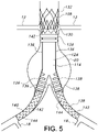
- a contralateral graft extension 138 may be used to deploy a contralateral graft extension 138, as depicted in FIG. 5 .
- the contralateral graft extension 138 is in an axial position which overlaps the contralateral leg 128 of the graft 114.
- the amount of desired overlap of the graft extension 138 with the contralateral leg 128 may vary depending on a variety of factors including vessel morphology, degree of vascular disease, patient status and the like. However, for some embodiments, the amount of axial overlap between the contralateral graft extension 138 and the contralateral leg 128 may be about 1 cm to about 5 cm, more specifically, about 2 cm to about 4 cm.
- the patient's hypogastric arteries may be used to serve as a positioning reference point to ensure that the hypogastric arteries are not blocked by the deployment.
- the distal end of a graft extension 138 or 140 may be deployed anywhere within a length of the ipsilateral leg 126 or contralateral leg 128 of the graft 114.
- additional graft extensions 140, 138 may be deployed within the already deployed graft extensions 140, 138 in order to achieve a desired length extension of the ipsilateral leg 126 or contralateral leg 128.
- graft extensions 138, 140 may be deployed on either the ipsilateral or contralateral sides of the graft assembly 114.
- Successive graft extensions 138, 140 may be deployed within each other so as to longitudinally overlap fluid flow lumens of successive graft extensions.
- Graft extensions 138, 140 which may be interchangeable for some embodiments, or any other suitable extension devices or portions of the main graft section 124 may include a variety of suitable configurations.
- graft extensions 138, 140 may include a polytetrafluoroethylene (PTFE) graft 142 with helical nitinol stent 144.
- PTFE polytetrafluoroethylene
- endovascular prosthesis 106 and/or graft extensions 138, 140 may be found in commonly owned U.S. Patent Nos. 6,395,019 ; 7,081,129 ; 7,147,660 ; 7,147,661 ; 7,150,758 ; 7,615,071 ; 7,766,954 and 8,167,927 and commonly owned U.S. Published Application No. 2009/0099649 .
- Details for the manufacture of the endovascular prosthesis 106 may be found in commonly owned U.S. Patent Nos. 6,776,604 ; 7,090,693 ; 7,125,464 ; 7,147,455 ; 7,678,217 and 7,682,475 .
- Useful inflation materials for the inflatable graft 114 may be found in may be found in commonly owned U.S. Published Application No. 2005/0158272 and 2006/0222596 . Additional details of an endovascular delivery system having a bifurcated and inflatable prosthesis having a tether from a contralateral leg to restrain movement of the contralateral leg with respect to an ipsilateral leg of the prosthesis may be found in commonly owned U.S. Provisional Application No. 61/660,105, entitled “Bifurcated Endovascular Prosthesis Having Tethered Contralateral Leg", filed on June 15, 2012 , and having Attorney Docket No. 1880-44P. Additional details of an endovascular delivery system including an improved hypotube may be found in commonly owned U.S. Provisional Application No. 61/660,103, entitled “Endovascular Delivery System With Flexible And Torqueable Hypotube”, filed on June 15, 2012 , and having Attorney Docket No. 1880-43P.
- Useful graft materials for the endovascular prosthesis 106 include, but are not limited, polyethylene; polypropylene; polyvinyl chloride; polytetrafluoroethylene (PTFE); fluorinated ethylene propylene; fluorinated ethylene propylene; polyvinyl acetate; polystyrene; poly(ethylene terephthalate); naphthalene dicarboxylate derivatives, such as polyethylene naphthalate, polybutylene naphthalate, polytrimethylene naphthalate and trimethylenediol naphthalate; polyurethane, polyurea; silicone rubbers; polyamides; polyimides; polycarbonates; polyaldehydes; polyether ether ketone; natural rubbers; polyester copolymers; silicone; styrene-butadiene copolymers; polyethers; such as fully or partially halogenated polyethers; and copolymers and combinations thereof.
- PTFE polytetrafluor
- the graft materials are non-textile graft materials, e.g., materials that are not woven, knitted, filament-spun, etc. that may be used with textile grafts.
- Such useful graft material may be extruded materials.
- Particularly useful materials include porous polytetrafluoroethylene without discernible node and fibril microstructure and (wet) stretched PTFE layer having low or substantially no fluid permeability that includes a closed cell microstructure having high density regions whose grain boundaries are directly interconnected to grain boundaries of adjacent high density regions and having substantially no node and fibril microstructure , and porous PTFE having no or substantially no fluid permeability.
- a porous PTFE layer having no or substantially no fluid permeability may have a Gurley Number of greater than about 12 hours, or up to a Gurley Number that is essentially infinite, or too high to measure, indicating no measurable fluid permeability.
- Some PTFE layers having substantially no fluid permeability may have a Gurley Number at 100 cc of air of greater than about 10 6 seconds.
- the Gurley Seconds is determined by measuring the time necessary for a given volume of air, typically, 25 cc, 100 cc or 300 cc, to flow through a standard 6.4516 cm 2 (1 square inch) of material or film under a standard pressure, such as 12.4 cm column of water. Such testing maybe carried out with a Gurley Densometer, made by Gurley Precision Instruments, Troy, New York. Details of such useful PTFE materials and methods for manufacture of the same may be found in commonly owned U.S. Patent Application Publication No. 2006/0233991 .
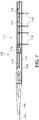
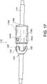
- FIG. 6 is a side elevational view of the endovascular delivery system 100 of the present invention.
- the endovascular delivery system 100 may include, among other things, the nosecone 120; the outer sheath 104; a retraction knob or handle 152 for the outer sheath 104; a flush port 154 for the outer sheath 104; an outer sheath radiopaque marker band 156; an inner tubular member 150; an inflation material or polymer fill connector port 158; an inflation material or polymer fill cap 160; a guidewire flush port 162; a guidewire flush port cap 164; a guidewire port 166; and nested stent release knobs 168; interrelated as shown.
- the flush port 154 for the outer sheath 104 may be used to flush the outer sheath 104 during delivery stages.
- the outer sheath 104 may have a radiopaque marker band to aid the practitioner in properly navigating the delivery system 100 to the desired bodily site.
- the outer sheath 104 is retractable by movement of the retraction knob or handle 152 for the outer sheath 104 by a practitioner towards the proximal handle assembly 170 of the delivery system 100.
- the inner tubular member 150 is disposed from the inner tubular member 150 toward a proximal portion of the delivery system 100.
- the inflation material or polymer fill connector port 158 and the inflation material or polymer fill cap 160 are useful for providing inflation material or polymer fill material to inflate proximal inflatable cuffs 134 and the network of inflatable channels 136 of the inflatable graft 114.
- the guidewire flush port 162 and the guidewire flush port cap 164 are useful for flushing the guidewire port 166 during delivery stages of the delivery system 100.
- the nested stent release knobs 168 contains a series of nested knobs (not shown) that that are used to engage release mechanisms for delivery of the endovascular prosthesis 106. Further details, including but not limited to methods, catheters and systems, for deployment of endovascular prostheses are disclosed in commonly owned U.S. Patent Nos. 6,761,733 and 6,733,521 and commonly owned U.S. Patent Application Publication Nos. 2006/0009833 and 2009/0099649 .
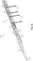
- FIG. 7 is a side elevational and partial cutaway view of the distal portion 172 of the endovascular delivery system 100 of the present invention
- FIG. 8 is a partial perspective and partial cutaway view of the distal portion 172 of the endovascular delivery system 100 of the present invention
- the distal portion 172 of the endovascular delivery system 100 includes a prosthesis/stent holder 174 disposed upon a prosthesis/stent holder guidewire 176.
- the holder 174 is useful releasably securing the endovascular prosthesis 106 (not shown) within the delivery system 100.
- the holder 174 inhibits or substantially inhibits undesirable longitudinal and/or circumferential movement of the endovascular prostheses 106 during delivery stages of the delivery system 100.
- Belts 110 serve to restrain the endovascular prosthesis 106 in a radially constrained stage until desired release of the endovascular prosthesis 106.
- the physician implanting the device will insert the device into the patient, using a series of radiopaque markers to align the prosthesis in the appropriate location.
- Typical delivery devices however, sometimes use radiopaque markers in the prosthesis itself to aid in proper placement of the device in the body.
- Use of radiopaque markers in the prosthesis itself can be insufficient due to the inherent radiopacity of some prostheses that makes identification and differentiation of such radiopaque markers difficult.
- FIG. 9 demonstrates an advantage of an embodiment of the current invention that includes two markers 200 and 202, which can be radiopaque.
- FIG. 9 is a cross sectional schematic view of a prosthesis delivery device along a longitudinal axis of guidewire 176, showing a first marker 200 and a second marker 202.
- the physician implanting the device typically views one or more images of the prosthesis and its delivery system, including markers 200 and 202, via fluoroscopy, which provides an image of the delivery system from a perspective that is generally perpendicular to the longitudinal axes of the delivery system and guidewire 176, as seen by the depiction of an eyesight in FIG. 9 .
- fluoroscopy provides an image of the delivery system from a perspective that is generally perpendicular to the longitudinal axes of the delivery system and guidewire 176, as seen by the depiction of an eyesight in FIG. 9 .
- the direction of eyesight is along the axis y.
- Guidewire 176 may be made of a radiopaque material.
- the gap 204 is at its maximum.
- the gap 204 becomes smaller.
- each marker 200, 202 is depicted with the symbol "R".
- the gap 204 between the first marker 200 and second marker 202 is denoted as Rcos ⁇ - Rsin ⁇ .
- the gap is denoted as Rcos ⁇ (ignoring the small effect of the width of guidewire 176).
- gap 204 may be as large as possible.
- the physician implanting the device may rotate the prosthesis until the gap between the markers is at its largest.
- vascular bodies within an individual may not have perfect symmetry along the guidewire 176 axis, or alternatively, along the axis of the catheter lumen, and a vascular prosthesis may be configured accordingly. As such, the placement of a prosthesis within these vascular bodies may require precise and accurate rotational alignment; that is, alignment of the device circumferentially along its longitudinal axis.
- cannulation of the contralateral limb aperture may be adversely affected if the device is not oriented properly.
- Proper orientation of the device allows the aortic body limbs to be positioned laterally, facilitating access to the contralateral gate via a guidewire/catheter inserted into the patient's contralateral access vessels.
- dgap/d ⁇ is approximately 11 times greater with embodiments containing two markers as compared to systems containing a single marker case.
- some embodiments contain at least one, and desirably two, additional markers, each disposed approximately at a +/- 90° angle from a first marker as measured from the longitudinal axis of guidewire 176.
- useful markers may simply be dots, squares, or bars that radiate from the center of the device. Desirably, the markers are oriented as far away from the center of the device as possible, to maximize the gap between the axis (and thus the guidewire) and the marker.
- each offset by approximately 90° relative to a first marker as described above greater than eleven times the rotational sensitivity to the gap may be afforded to the physician implanting the prosthesis, thus allowing significantly more control in the alignment of the prosthesis during implantation.
- Such embodiments solve or mitigate problems with systems having a single marker as outlined above, because by virtue of the additional markers being offset by approximately 90° at least one of the markers will always be in a position to contribute high rotational angle sensitivity during the prosthesis implantation procedure (i.e., either the sin ⁇ or cos ⁇ term in the "gap equation" will be operative). This allows the physician to have improved prosthesis placement sensitivity during its implantation, and particular, increased placement sensitivity when performing any rotational maneuvers during the implantation procedure.
- An improved radiopaque marker system may be useful for the user to accurately deliver a prosthesis.
- the device may include a series of markers, as will be described below. The description below includes a series of markers in one component of the delivery system, specifically the prosthesis holder. However, it will be understood that the marker system described herein may be useful in any portion of the delivery system, including, for example, the sheath or nosecone.
- the delivery system may include a separate component including the marker system and the purpose of this separate component is to provide the marker system to the delivery system.
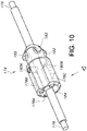
- FIGS. 10-17 show an embodiment of an improved radiopaque marker system as described herein.
- FIG. 10 shows a rear and front perspective view of components of the system, respectively.
- a prosthesis/stent holder guidewire 176 extends through a central lumen 184 disposed in prosthesis/stent holder 174, thus forming a longitudinal axis of lumen 184 that is coincident with a longitudinal axis of guidewire 176 when so configured. Further, in the embodiment depicted in FIG. 10 , the prosthesis/stent holder guidewire 176 fully extends through the prosthesis/stent holder lumen 184 such that the prosthesis/stent holder guidewire is exposed at each end of the prosthesis/stent holder 174.
- Guidewire 176 may be made of any desired material.
- guidewire 176 is made from a material that is viewable via radiography, fluoroscopy or other visualization techniques.
- materials may be metal, such as palladium, iridium, gold, tantalum, tungsten, platinum, and combinations thereof.
- the material may be a polymeric material, such as a radiopaque nylon.
- the material may include fillers that are radiopaque, such as bismuth, barium, and tungsten.
- the present invention contemplates using a guidewire 176 to aid in placement of the prosthesis, the use of the guidewire 176 for final placement is optional. That is, the guidewire 176 could be retracted, or not used at all, and the markers in the prosthesis/stent holder 174 can be used to provide guidance as to the proper rotational alignment of the prosthesis.
- axially aligned markers 178A, 178B, 178C which are all parallel to the axis formed by the axial guidewire 176.
- the three axially aligned markers 178A, 178B, 178C are depicted in the Figures as being generally cylindrical, it is understood that any suitable markers may be used, including, for example, dots or a series of dots, or bars.
- the three axially aligned markers 178A, 178B, 178C are positioned at approximately 90° intervals around the circumference of the prosthesis/stent holder 174 and separated from the prosthesis/stent holder guidewire 176 by a suitable known distance.
- the three axially aligned markers 178A, 178B, 178C in some embodiments are each of the same length and the same diameter, although some variation in sizing may occur. Further, each of the three axially aligned markers 178A, 178B, 178C are separated from the prosthesis/stent holder guidewire 176 by the same distance, thus creating the same gap size therebetween.
- Markers 178A, 178B, 178C may be made from any desired material visible with imaging modality used in a deployment procedure, including a radiopaque material, such as platinum, iridium, palladium, gold, tantalum, tungsten, radiopaque nylon, bismuth, barium, tungsten or combinations thereof.
- a radiopaque material such as platinum, iridium, palladium, gold, tantalum, tungsten, radiopaque nylon, bismuth, barium, tungsten or combinations thereof.
- each of the three axially aligned markers 178A, 178B, 178C are made from the same material, although it is not necessary.
- markers 178A, 178B, 178C are made from a combination of 90% by weight platinum and 10% by weight iridium.
- Markers 178A, 178B, 178C may be the same or different shape, and may be cylindrical as shown in FIG.
- markers 178A, 178B, 178C may be of a hollow, partially hollow, or solid construction.
- the markers may be a series of discontinuous markers, such as spheres or cubes, which create the ability to view the gap 186 upon rotation of the device.
- diameter D176 of the prosthesis/stent holder guidewire 176 may be equal to or larger than the diameter D178A, D178B, D178C of each of the three axially aligned markers 178A, 178B, 178C.
- the diameter of the prosthesis/stent holder guidewire 176 may be from about 0.0254 cm (0.010 inches) to about 0.1524 cm (0.060 inches), or approximately 0.030 to about 0.127 cm (0.050 inches), and the diameter of each of the three axially aligned markers 178A, 178B, 178C is approximately 0.0254 cm (0.010 inches) to about 0.1524 cm (0.060 inches), or approximately 0.0508 cm (0.020 inches) to about 0.0762 cm (0.030 inches).
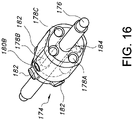
- the prosthesis/stent holder 174 may optionally include one or more than one markers 180A, 180B which may be radiopaque and are disposed such that their axial length along a direction that is approximately 90° (perpendicular) to the axis of the prosthesis/stent holder guidewire 176.
- markers 180A, 180B may be made from the same material as the three axially aligned markers 178A, 178B, 178C and/or the prosthesis/stent holder guidewire 176, or may be made from a different radiopaque material.
- Markers 180A, 180B may be cylindrical in shape, but may take any desired shape as described for markers 178A-C. Inclusion of markers 180A, 180B is optional, as they further aid in the alignment of the prosthetic device.
- the prosthesis/stent holder 174 in the embodiment shown in FIGS. 10-17 includes a series of crown anchors 182 that secure the prosthesis/stent in place before and during implantation.
- the crowns of the prosthetic stent (not shown) may be secured around the crown anchors 182, thus preventing rotational movement of the stent before and during implantation.
- the prosthesis/stent holder 174 and crown anchors 182 may be made from any desired material, including a non-radiopaque material to allow a physician to more readily visualize the radiopaque markers and the guidewire 176 during implantation.
- Markers 178A, 178B, 178C, 180A and 180B may be formed and assembled into the system by any suitable means.
- One or more of the markers may be press fitted into the prosthesis/stent holder 174; alternatively, one or more of the markers may be molded into the prosthesis/stent holder 174, so that they are fully or partially encapsulated within the material comprising holder 174.
- one or more of the markers may be press fitted and secured with a suitable adhesive, such as a UV or cyanoacrylate adhesive.
- FIG. 11 shows a side view of the prosthesis/stent holder 174 of the embodiment shown in FIG. 10 .
- the side view of FIG. 11 is at a viewing angle whereby the longitudinal axes of markers 178A and 178C are visually aligned in an overlapping manner with the longitudinal axis of guidewire 176 disposed within lumen 184 of holder 174.
- This view may be, for example, a view that a physician will have when implanting the prosthesis in the vasculature under, e.g., fluoroscopy.
- this a baseline configuration in which there has been no rotation of the prosthesis/stent holder 174 relative to the line of sight of the user, indicated in FIGS. 10 and 13 (that is, ⁇ is zero).
- a gap 186 is visible between an outer surface or circumference of the second axially aligned marker 178B and the surface of prosthesis/stent holder guidewire 176.
- the projection of the gap 186 as viewed by the user along the sight of axis y is measured between the outer surface or circumference of the guidewire 176 and the outer surface of the second axially aligned marker 178B.
- markers 178A, 178C are visually aligned with the prosthesis/stent holder guidewire 176 such that they largely or completely overlap. Under fluorescopy, then, markers 178A, 178C cannot readily be seen in this alignment, since the guidewire 176 is wider than the markers 178A, 178C in this particular embodiment.
- gap 186 is at its largest.
- the gap 186 as viewed by the user in this configuration may be as large as possible, which is dependent upon the size of the catheter used.
- the marker diameter D178 may be kept to as minimum as possible while still allowing the user to view the marker 178 via imaging device. If the material from which the markers 178 are made is extremely radiopaque, a smaller or thinner marker 178 may be used and still provide the user with visibility with an imaging device.
- a radiopaque marker 178 may have a diameter of from about 0.0254 cm (0.010 inches) to about 0.127 cm (0.050 inches), or from about 0.0508 cm (0.020 inches) to about 0.1016 cm (0.040 inches).
- the gap may have a size of about 0.0254 cm (0.010 inch) to about 0.2032 cm (0.080 inches).
- a gap space for typical prosthetic systems such as those described herein may be from about 0.0508 cm (0.020 inches) to about 0.1651 cm (0.065 inch), or may be from about 0.0889 cm (0.035 inches) to about 0.1397 cm (0.055 inches).
- a larger gap may be used to provide the user with ease of viewing even with lower quality imaging systems or less radiopaque materials.
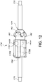
- FIG. 12 shows the system of FIG. 11 that has been rotated in a clockwise direction about guidewire 176 longitudinal axis by approximately 10°.
- markers 178A, 178B, 178C have all now been rotated clockwise.
- a portion of marker 178C would now be visible in this view under, e.g., fluoroscopy, as extending slightly above the boundary or outer surface of guidewire 176.
- a portion of marker 178A would now be visible as extending in this view slightly below the boundary or outer surface of guidewire 176.
- Marker 178B now appears to be closer to the guidewire 176 when viewed from this angle as the length of gap 186 is now smaller compared to its length in the direct alignment view of FIG. 11 .
- the gap 186 is affected to a greater degree even with a small rotation of the prosthesis/stent holder 174. This greater reduction in gap 186 size during rotation of the device compared to systems with a single marker or a different configuration allows for greater precision during implantation.
- the gap 186 may be minimized whether the device is turned in the clockwise or counterclockwise direction.
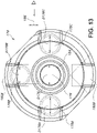
- FIG. 13 shows a view of the prosthesis/stent holder 174 transverse to its longitudinal axis and longitudinal axis of its lumen 184 and the coincident longitudinal axis of guidewire 176 (extending in a normal direction out of the plane of the page).
- guidewire 176 extends through lumen 184 of the prosthesis/stent holder 174.
- three axially aligned markers 178A, 178B and 178C are disposed around the guidewire 176, which may be spaced at approximately 90° intervals and at an equal distance from the guidewire 176. Projection of the gap 186, described with respect to the views of FIGS. 11 and 12 , is also shown.
- FIG. 14 shows the prosthesis/stent holder 174 as viewed from the top
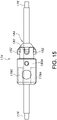
- FIG. 15 shows the prosthesis/stent holder 174 as viewed from the bottom (both relative to the orientation of the components in the FIG. 13 view).
- the middle marker 178B when viewed from the bottom, in direct alignment, the middle marker 178B, even if radiopaque, would be difficult or impossible to visualize by a deploying physician under, e.g., fluoroscopy, as it is shielded from view by a radiopaque guidewire 176.
- FIGS. 16 and 17 show a front perspective view and side view, respectively, after the prosthesis/stent holder 174 has been rotated slightly. As can be seen, the angles and gaps formed by the surface of guidewire 176 and the surfaces of axially aligned markers 178A, 178B, 178C are changed due to the rotation of the prosthesis/stent holder 174.
- FIG. 18 is a chart depicting the change in the gap 186 between the guidewire 176 and an axially aligned marker 178A, 178B, or 178C, depending upon the angle of rotation, as an embodiment of the prosthesis/stent holder 174 is rotated about its longitudinal axis.
- the chart shows the change in the gap (using three axially aligned markers 178A, 178B, 178C) as compared to the change of an identically-defined gap in a device that uses only one axially aligned marker (e.g., 178B) during identical rotation.
- the size of gap 186 is reduced at a greater rate than in a device using one marker for a given angle of rotation.
- the prosthesis/stent holder 174 need only be rotated about 22 degrees. In a device using only one axially aligned marker, however, the prosthesis/stent holder need be rotated about 50 degrees.
- the inventive design provides a significantly greater degree of accuracy during rotation than other devices.
- Any shape or layout of markers 178A, 178B, 178C may be used, including, as explained above, continuous markers such as cylinders or discontinuous markers such as a series of dots, spheres, cubes, and the like.
- different shaped markers may be used in the same device, to allow the user to be able to differentiate between the markers in the device and allow for even greater precision.
- marker 178A can be a series of spherical dots
- marker 178C can be a series of cubes. As the device is rotated and the relative markers 178A, 178C can be seen by the user, the difference in shape may allow the user to have even greater control and precision.
- the present invention may be used to deliver any desired devices, including stents, stent grafts, and the like. Bifurcated and fenestrated devices may be implanted using the present invention.
- the device may be used to aid in placement of devices in other locations, including, for example, in cranial implantation. Further, although the present invention is quite useful in aiding alignment when viewed from the side angle, the device may also be useful in providing alignment in axial or quasi-axial views. Various elements of the device create angles and gaps upon rotation when viewed from different angles, and thus the present invention may be useful in various other embodiments.
- the inventive device has been explained with reference to the prosthesis/stent holder 174, but it is noted that the axially aligned marker system explained herein may be useful in other locations and other components of the delivery device.
- a device is prepared for implantation including the prosthesis/stent holder 174 described above, with a stent-graft prosthesis secured to the prosthesis/stent holder 174.
- the stent-graft prosthesis is secured to the prosthesis/stent holder 174 as explained above and the delivery device is prepared for implantation.
- the delivery device including prosthesis/stent holder 174 as explained above.
- the delivery device includes a prosthesis secured thereto, such as a stent-graft.
- the user typically a physician, inserts the delivery device into the patient's body, more particularly, into the desired bodily lumen into which the prosthesis is to be implanted.
- the physician uses fluoroscopy to view radiopaque materials in the delivery device and prosthesis on a display device. As the device is being directed to its desired location, the physician views the location of the device via the display, which shows the presence of various radiopaque markers within the body.
- the physician may then adjust the rotation of the device to ensure proper rotational/circumferential alignment.
- the physician rotates the prosthesis until the gap between the axially aligned radiopaque markers 178 and the prosthesis/stent holder guidewire 176 is at its largest and on the intended side of the guidewire 176.
- the prosthesis is in proper rotational alignment, and the prosthesis may be implanted with greater confidence that might otherwise be possible.
- the delivery device is withdrawn.
- one or more of the additional prosthetic parts may employ the improved radiopaque marker system as explained above, thereby ensuring proper rotational/circumferential placement of each prosthetic part.
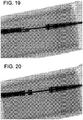
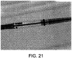
- FIGS. 19-21 show various positions of a radiopaque marker system of the present invention, as seen under fluoroscopy.
- FIG. 19 shows the device in the ipsilateral right position
- FIG. 20 shows the device in the anterior-posterior position
- FIG. 21 shows the device in the ipsilateral left position.
- the middle marker is visible, while the two side markers are superimposed on the radiopaque guidewire.
- the two perpendicular markers are clearly visible.
- FIG. 20 is oriented such that the middle marker is superimposed on the guidewire, while the two side markers are visible.
Landscapes
- Health & Medical Sciences (AREA)
- Engineering & Computer Science (AREA)
- Biomedical Technology (AREA)
- Cardiology (AREA)
- Oral & Maxillofacial Surgery (AREA)
- Transplantation (AREA)
- Heart & Thoracic Surgery (AREA)
- Vascular Medicine (AREA)
- Life Sciences & Earth Sciences (AREA)
- Animal Behavior & Ethology (AREA)
- General Health & Medical Sciences (AREA)
- Public Health (AREA)
- Veterinary Medicine (AREA)
- Prostheses (AREA)
Applications Claiming Priority (2)
| Application Number | Priority Date | Filing Date | Title |
|---|---|---|---|
| US201261660413P | 2012-06-15 | 2012-06-15 | |
| PCT/US2013/043615 WO2013188132A1 (en) | 2012-06-15 | 2013-05-31 | Endovascular delivery system with an improved radiopaque marker scheme |
Publications (2)
| Publication Number | Publication Date |
|---|---|
| EP2861189A1 EP2861189A1 (en) | 2015-04-22 |
| EP2861189B1 true EP2861189B1 (en) | 2022-12-28 |
Family
ID=48741485
Family Applications (1)
| Application Number | Title | Priority Date | Filing Date |
|---|---|---|---|
| EP13733113.8A Active EP2861189B1 (en) | 2012-06-15 | 2013-05-31 | Endovascular delivery system with an improved radiopaque marker scheme |
Country Status (4)
| Country | Link |
|---|---|
| US (4) | US9233015B2 (enExample) |
| EP (1) | EP2861189B1 (enExample) |
| JP (1) | JP6085845B2 (enExample) |
| WO (1) | WO2013188132A1 (enExample) |
Families Citing this family (66)
| Publication number | Priority date | Publication date | Assignee | Title |
|---|---|---|---|---|
| DE102007043830A1 (de) | 2007-09-13 | 2009-04-02 | Lozonschi, Lucian, Madison | Herzklappenstent |
| WO2011072084A2 (en) | 2009-12-08 | 2011-06-16 | Avalon Medical Ltd. | Device and system for transcatheter mitral valve replacement |
| EP3705090B1 (en) | 2011-08-11 | 2023-12-06 | Tendyne Holdings, Inc. | Improvements for prosthetic valves and related inventions |
| EP2775958B1 (en) | 2011-11-11 | 2017-01-04 | Bolton Medical, Inc. | Universal endovascular grafts |
| US9827092B2 (en) | 2011-12-16 | 2017-11-28 | Tendyne Holdings, Inc. | Tethers for prosthetic mitral valve |
| US9233015B2 (en) * | 2012-06-15 | 2016-01-12 | Trivascular, Inc. | Endovascular delivery system with an improved radiopaque marker scheme |
| WO2014022124A1 (en) | 2012-07-28 | 2014-02-06 | Tendyne Holdings, Inc. | Improved multi-component designs for heart valve retrieval device, sealing structures and stent assembly |
| US9675454B2 (en) | 2012-07-30 | 2017-06-13 | Tendyne Holdings, Inc. | Delivery systems and methods for transcatheter prosthetic valves |
| US11406498B2 (en) | 2012-12-20 | 2022-08-09 | Philips Image Guided Therapy Corporation | Implant delivery system and implants |
| WO2014110254A1 (en) | 2013-01-10 | 2014-07-17 | Trivascular, Inc. | Gate wire for contralateral leg access |
| US9655754B2 (en) | 2013-01-10 | 2017-05-23 | Trivascular, Inc. | Systems and methods for guidewire crossover for bifurcated prostheses |
| US9486306B2 (en) | 2013-04-02 | 2016-11-08 | Tendyne Holdings, Inc. | Inflatable annular sealing device for prosthetic mitral valve |
| US10463489B2 (en) | 2013-04-02 | 2019-11-05 | Tendyne Holdings, Inc. | Prosthetic heart valve and systems and methods for delivering the same |
| US11224510B2 (en) | 2013-04-02 | 2022-01-18 | Tendyne Holdings, Inc. | Prosthetic heart valve and systems and methods for delivering the same |
| US10478293B2 (en) | 2013-04-04 | 2019-11-19 | Tendyne Holdings, Inc. | Retrieval and repositioning system for prosthetic heart valve |
| US9610159B2 (en) | 2013-05-30 | 2017-04-04 | Tendyne Holdings, Inc. | Structural members for prosthetic mitral valves |
| AU2014302505B2 (en) | 2013-06-25 | 2019-11-28 | Tendyne Holdings, Inc. | Thrombus management and structural compliance features for prosthetic heart valves |
| WO2015017689A1 (en) | 2013-08-01 | 2015-02-05 | Robert Vidlund | Epicardial anchor devices and methods |
| WO2015058039A1 (en) | 2013-10-17 | 2015-04-23 | Robert Vidlund | Apparatus and methods for alignment and deployment of intracardiac devices |
| EP3062744B1 (en) | 2013-10-28 | 2020-01-22 | Tendyne Holdings, Inc. | Prosthetic heart valve and systems for delivering the same |
| US9526611B2 (en) | 2013-10-29 | 2016-12-27 | Tendyne Holdings, Inc. | Apparatus and methods for delivery of transcatheter prosthetic valves |
| WO2015105530A1 (en) | 2014-01-09 | 2015-07-16 | Trivascular, Inc. | Systems and methods for guidewire crossover for bifurcated prostheses |
| WO2015120122A2 (en) | 2014-02-05 | 2015-08-13 | Robert Vidlund | Apparatus and methods for transfemoral delivery of prosthetic mitral valve |
| US9986993B2 (en) | 2014-02-11 | 2018-06-05 | Tendyne Holdings, Inc. | Adjustable tether and epicardial pad system for prosthetic heart valve |
| AU2015229708B2 (en) | 2014-03-10 | 2019-08-15 | Tendyne Holdings, Inc. | Devices and methods for positioning and monitoring tether load for prosthetic mitral valve |
| US20150250481A1 (en) * | 2014-03-10 | 2015-09-10 | Trivascular, Inc. | Inflatable occlusion wire-balloon for aortic applications |
| CN106255457B (zh) * | 2014-04-11 | 2020-08-21 | 皇家飞利浦有限公司 | 植入物递送系统以及植入物 |
| ES2731434T3 (es) | 2014-09-23 | 2019-11-15 | Bolton Medical Inc | Dispositivos de reparación vascular |
| WO2016059084A2 (en) * | 2014-10-13 | 2016-04-21 | Symetis Sa | Catheter delivery system for stent valve |
| US9956101B2 (en) | 2014-12-04 | 2018-05-01 | Trivascular, Inc. | Internal iliac preservation devices and methods |
| US10149777B2 (en) * | 2014-12-18 | 2018-12-11 | Cook Medical Technologies Llc | Orientation marker on pusher for deployment of endoluminal prostheses |
| CN107405195B (zh) | 2015-01-07 | 2020-09-08 | 坦迪尼控股股份有限公司 | 人造二尖瓣以及用于递送人造二尖瓣的设备和方法 |
| ES2877699T3 (es) | 2015-02-05 | 2021-11-17 | Tendyne Holdings Inc | Válvula cardiaca protésica con ligación y almohadilla epicárdica expandible |
| EP3283010B1 (en) | 2015-04-16 | 2020-06-17 | Tendyne Holdings, Inc. | Apparatus for delivery and repositioning of transcatheter prosthetic valves |
| US20180110609A1 (en) | 2015-05-11 | 2018-04-26 | Trivascular, Inc. | Stent-graft with improved flexibility |
| EP3328326A4 (en) * | 2015-07-30 | 2019-03-20 | TriVascular, Inc. | DEVICES AND METHODS FOR USING AN ENDOLUMINAL PROTECTION |
| US10327894B2 (en) | 2015-09-18 | 2019-06-25 | Tendyne Holdings, Inc. | Methods for delivery of prosthetic mitral valves |
| EP4309628A3 (en) | 2015-12-03 | 2024-04-10 | Tendyne Holdings, Inc. | Frame features for prosthetic mitral valves |
| WO2017117109A1 (en) | 2015-12-28 | 2017-07-06 | Tendyne Holdings, Inc. | Atrial pocket closures for prosthetic heart valves |
| US10052185B2 (en) | 2016-02-12 | 2018-08-21 | Covidien Lp | Vascular device marker attachment |
| US10265089B2 (en) | 2016-02-12 | 2019-04-23 | Covidien Lp | Vascular device visibility |
| WO2017176730A1 (en) | 2016-04-05 | 2017-10-12 | Bolton Medical, Inc. | Stent graft with internal tunnels and fenestrations and methods of use |
| US10470877B2 (en) | 2016-05-03 | 2019-11-12 | Tendyne Holdings, Inc. | Apparatus and methods for anterior valve leaflet management |
| WO2017218375A1 (en) | 2016-06-13 | 2017-12-21 | Tendyne Holdings, Inc. | Sequential delivery of two-part prosthetic mitral valve |
| EP3478224B1 (en) | 2016-06-30 | 2022-11-02 | Tendyne Holdings, Inc. | Prosthetic heart valves and apparatus for delivery of same |
| WO2018013515A1 (en) | 2016-07-12 | 2018-01-18 | Tendyne Holdings, Inc. | Apparatus and methods for trans-septal retrieval of prosthetic heart valves |
| US11096781B2 (en) | 2016-08-01 | 2021-08-24 | Edwards Lifesciences Corporation | Prosthetic heart valve |
| US11045177B2 (en) | 2016-11-02 | 2021-06-29 | Daniel Ezra Walzman | Orientable intracranial occlusion device and method |
| US11638655B2 (en) | 2016-11-02 | 2023-05-02 | Daniel Ezra Walzman | Orientable intracranial occlusion device and method |
| WO2019014473A1 (en) | 2017-07-13 | 2019-01-17 | Tendyne Holdings, Inc. | PROSTHETIC CARDIAC VALVES AND ASSOCIATED APPARATUS AND METHODS FOR IMPLEMENTING THE SAME |
| AU2018323900A1 (en) | 2017-08-28 | 2020-02-27 | Tendyne Holdings, Inc. | Prosthetic heart valves with tether coupling features |
| US10441449B1 (en) | 2018-05-30 | 2019-10-15 | Vesper Medical, Inc. | Rotary handle stent delivery system and method |
| US10449073B1 (en) | 2018-09-18 | 2019-10-22 | Vesper Medical, Inc. | Rotary handle stent delivery system and method |
| WO2020251777A1 (en) | 2019-06-12 | 2020-12-17 | Walzman Daniel Ezra | Orientable intracranial occlusion device and method |
| JP7558984B2 (ja) * | 2019-06-12 | 2024-10-01 | ウォルツマン,ダニエル,エズラ | 血管内器具 |
| US12364615B2 (en) | 2019-06-12 | 2025-07-22 | Daniel Ezra Walzman | Orientable intracranial occlusion device and method |
| US12303413B2 (en) | 2019-06-12 | 2025-05-20 | Daniel Ezra Walzman | Orientable implantable device and method |
| US11446470B2 (en) * | 2019-06-24 | 2022-09-20 | Medtronic, Inc. | Catheter handle with torque mechanism and valve relief component |
| US12611522B2 (en) | 2019-06-24 | 2026-04-28 | Medtronic, Inc. | Catheter handle with torque mechanism and valve relief component |
| EP3831343B1 (en) | 2019-12-05 | 2024-01-31 | Tendyne Holdings, Inc. | Braided anchor for mitral valve |
| US11648114B2 (en) | 2019-12-20 | 2023-05-16 | Tendyne Holdings, Inc. | Distally loaded sheath and loading funnel |
| US11951002B2 (en) | 2020-03-30 | 2024-04-09 | Tendyne Holdings, Inc. | Apparatus and methods for valve and tether fixation |
| US11219541B2 (en) | 2020-05-21 | 2022-01-11 | Vesper Medical, Inc. | Wheel lock for thumbwheel actuated device |
| WO2022039853A1 (en) | 2020-08-19 | 2022-02-24 | Tendyne Holdings, Inc. | Fully-transseptal apical pad with pulley for tensioning |
| CN216854956U (zh) | 2020-08-24 | 2022-07-01 | 爱德华兹生命科学公司 | 假体心脏瓣膜 |
| US20230190502A1 (en) * | 2021-12-20 | 2023-06-22 | Medtronic Vascular, Inc. | Delivery system for delivering a cardiovascular device |
Family Cites Families (345)
| Publication number | Priority date | Publication date | Assignee | Title |
|---|---|---|---|---|
| US4041931A (en) | 1976-05-17 | 1977-08-16 | Elliott Donald P | Radiopaque anastomosis marker |
| US4202349A (en) | 1978-04-24 | 1980-05-13 | Jones James W | Radiopaque vessel markers |
| US4616652A (en) | 1983-10-19 | 1986-10-14 | Advanced Cardiovascular Systems, Inc. | Dilatation catheter positioning apparatus |
| US5669936A (en) | 1983-12-09 | 1997-09-23 | Endovascular Technologies, Inc. | Endovascular grafting system and method for use therewith |
| US5275622A (en) * | 1983-12-09 | 1994-01-04 | Harrison Medical Technologies, Inc. | Endovascular grafting apparatus, system and method and devices for use therewith |
| US4917088A (en) | 1985-05-02 | 1990-04-17 | C. R. Bard, Inc. | Balloon dilation probe |
| US5102390A (en) | 1985-05-02 | 1992-04-07 | C. R. Bard, Inc. | Microdilatation probe and system for performing angioplasty in highly stenosed blood vessels |
| US4733665C2 (en) * | 1985-11-07 | 2002-01-29 | Expandable Grafts Partnership | Expandable intraluminal graft and method and apparatus for implanting an expandable intraluminal graft |
| JPS62261371A (ja) * | 1986-05-08 | 1987-11-13 | テルモ株式会社 | カテ−テル |
| US4762128A (en) | 1986-12-09 | 1988-08-09 | Advanced Surgical Intervention, Inc. | Method and apparatus for treating hypertrophy of the prostate gland |
| US4793359A (en) | 1987-04-24 | 1988-12-27 | Gv Medical, Inc. | Centering balloon structure for transluminal angioplasty catheter |
| US4796637A (en) | 1987-06-17 | 1989-01-10 | Victory Engineering Company | Radiopaque marker for stereotaxic catheter |
| US4781681A (en) | 1987-09-15 | 1988-11-01 | Gv Medical, Inc. | Inflatable tip for laser catheterization |
| US4830003A (en) | 1988-06-17 | 1989-05-16 | Wolff Rodney G | Compressive stent and delivery system |
| WO1990001969A1 (en) | 1988-08-24 | 1990-03-08 | Slepian Marvin J | Biodegradable polymeric endoluminal sealing |
| CA1301007C (en) | 1989-01-30 | 1992-05-19 | Geoffrey S. Martin | Angioplasty catheter with spiral balloon |
| US5007434A (en) | 1989-02-07 | 1991-04-16 | Advanced Cardiovascular Systems, Inc. | Catheter tip attitude controlling guide wire |
| US4928693A (en) | 1989-03-13 | 1990-05-29 | Schneider (Usa), Inc. | Pressure monitor catheter |
| US4976690A (en) | 1989-08-10 | 1990-12-11 | Scimed Life Systems, Inc. | Variable stiffness angioplasty catheter |
| US5476100A (en) | 1994-07-07 | 1995-12-19 | Guided Medical Systems, Inc. | Catheter steerable by directional jets with remotely controlled closures |
| US5318529A (en) | 1989-09-06 | 1994-06-07 | Boston Scientific Corporation | Angioplasty balloon catheter and adaptor |
| US5158084A (en) | 1989-11-22 | 1992-10-27 | Board Of Regents, The University Of Texas System | Modified localization wire for excisional biopsy |
| US7033325B1 (en) | 1989-12-19 | 2006-04-25 | Scimed Life Systems, Inc. | Guidewire with multiple radiopaque marker sections |
| US5209730A (en) | 1989-12-19 | 1993-05-11 | Scimed Life Systems, Inc. | Method for placement of a balloon dilatation catheter across a stenosis and apparatus therefor |
| US5209749A (en) | 1990-05-11 | 1993-05-11 | Applied Urology Inc. | Fluoroscopically alignable cutter assembly and method of using the same |
| US5034005A (en) | 1990-07-09 | 1991-07-23 | Appling William M | Radiopaque marker |
| IT9084979A1 (it) | 1990-07-30 | 1992-01-30 | Imad Sheiban | Catetere per angioplastica coronarica transluminale percutanea con due palloncini alla sua estremita' distale uno di diametro piccolo (1, 5mm. seguito da un altro palloncino di diametro maggiore variabile da 2, 5 a 4 mm il palloncino piccolo ha la fu |
| US5395332A (en) | 1990-08-28 | 1995-03-07 | Scimed Life Systems, Inc. | Intravascualr catheter with distal tip guide wire lumen |
| US5246420A (en) | 1990-11-19 | 1993-09-21 | Danforth Biomedical Incorporated | Highly steerable dilatation balloon catheter system |
| US5174302A (en) | 1990-12-04 | 1992-12-29 | Cordis Corporation | Variable radiopacity guidewire with spaced highly radiopaque regions |
| CA2065634C (en) | 1991-04-11 | 1997-06-03 | Alec A. Piplani | Endovascular graft having bifurcation and apparatus and method for deploying the same |
| JP2939893B2 (ja) | 1991-04-24 | 1999-08-25 | バクスター インターナショナル インコーポレーテッド | 交換可能な一体式−ワイヤーバルーンカテーテル |
| US5263928A (en) | 1991-06-14 | 1993-11-23 | Baxter International Inc. | Catheter and endoscope assembly and method of use |
| CA2068584C (en) | 1991-06-18 | 1997-04-22 | Paul H. Burmeister | Intravascular guide wire and method for manufacture thereof |
| US5253653A (en) | 1991-10-31 | 1993-10-19 | Boston Scientific Corp. | Fluoroscopically viewable guidewire for catheters |
| US5318032A (en) | 1992-02-05 | 1994-06-07 | Devices For Vascular Intervention | Guiding catheter having soft tip |
| US5944712A (en) | 1992-03-02 | 1999-08-31 | Medtronic Ave, Inc. | Catheter size designation system |
| US5353808A (en) | 1992-03-04 | 1994-10-11 | Cordis Corporation | Guidewire having distally located marker segment |
| US5203777A (en) | 1992-03-19 | 1993-04-20 | Lee Peter Y | Radiopaque marker system for a tubular device |
| ZA931943B (en) | 1992-03-30 | 1993-11-16 | Pameda Nv | Inflatable shaft catheter |
| US5261878A (en) | 1992-05-19 | 1993-11-16 | The Regents Of The University Of California | Double balloon pediatric ductus arteriosus stent catheter and method of using the same |
| US5707376A (en) | 1992-08-06 | 1998-01-13 | William Cook Europe A/S | Stent introducer and method of use |
| US5562725A (en) | 1992-09-14 | 1996-10-08 | Meadox Medicals Inc. | Radially self-expanding implantable intraluminal device |
| US5315747A (en) | 1992-10-30 | 1994-05-31 | Pameda N.V. | Method of preparing a balloon dilatation catheter |
| US5413557A (en) | 1993-08-24 | 1995-05-09 | Pameda N.V. | Dilatation catheter with eccentric balloon |
| US5336178A (en) | 1992-11-02 | 1994-08-09 | Localmed, Inc. | Intravascular catheter with infusion array |
| US5480423A (en) * | 1993-05-20 | 1996-01-02 | Boston Scientific Corporation | Prosthesis delivery |
| US5318535A (en) | 1993-06-21 | 1994-06-07 | Baxter International Inc. | Low-profile dual-lumen perfusion balloon catheter with axially movable inner guide sheath |
| US5458615A (en) | 1993-07-06 | 1995-10-17 | Advanced Cardiovascular Systems, Inc. | Stent delivery system |
| DE69330132T2 (de) | 1993-07-23 | 2001-11-15 | Cook Inc., Bloomington | Flexibler stent mit einer aus einem materialbogen geformten konfiguration |
| US6113576A (en) | 1993-08-04 | 2000-09-05 | Lake Region Manufacturing, Inc. | Thrombolysis catheter system with fixed length infusion zone |
| CA2125258C (en) | 1993-08-05 | 1998-12-22 | Dinah B Quiachon | Multicapsule intraluminal grafting system and method |
| US5669880A (en) | 1993-08-24 | 1997-09-23 | Cordis Corporation | Stent delivery system |
| US5429605A (en) | 1994-01-26 | 1995-07-04 | Target Therapeutics, Inc. | Microballoon catheter |
| US5479938A (en) | 1994-02-07 | 1996-01-02 | Cordis Corporation | Lumen diameter reference guidewire |
| US6051020A (en) | 1994-02-09 | 2000-04-18 | Boston Scientific Technology, Inc. | Bifurcated endoluminal prosthesis |
| US5609627A (en) | 1994-02-09 | 1997-03-11 | Boston Scientific Technology, Inc. | Method for delivering a bifurcated endoluminal prosthesis |
| US6165213A (en) | 1994-02-09 | 2000-12-26 | Boston Scientific Technology, Inc. | System and method for assembling an endoluminal prosthesis |
| US5429597A (en) | 1994-03-01 | 1995-07-04 | Boston Scientific Corporation | Kink resistant balloon catheter and method for use |
| US5948489A (en) | 1994-03-03 | 1999-09-07 | Cordis Corporation | Catheter having extruded, flexible, pliable and compliant marker band |
| US5406960A (en) | 1994-04-13 | 1995-04-18 | Cordis Corporation | Guidewire with integral core and marker bands |
| US5824044A (en) | 1994-05-12 | 1998-10-20 | Endovascular Technologies, Inc. | Bifurcated multicapsule intraluminal grafting system |
| US5683451A (en) | 1994-06-08 | 1997-11-04 | Cardiovascular Concepts, Inc. | Apparatus and methods for deployment release of intraluminal prostheses |
| US5824041A (en) * | 1994-06-08 | 1998-10-20 | Medtronic, Inc. | Apparatus and methods for placement and repositioning of intraluminal prostheses |
| US5743874A (en) | 1994-08-29 | 1998-04-28 | Fischell; Robert E. | Integrated catheter for balloon angioplasty and stent delivery |
| US6331188B1 (en) | 1994-08-31 | 2001-12-18 | Gore Enterprise Holdings, Inc. | Exterior supported self-expanding stent-graft |
| US5558652A (en) | 1994-10-06 | 1996-09-24 | B. Braun Medical, Inc. | Introducer with radiopaque marked tip and method of manufacture therefor |
| CA2163708C (en) | 1994-12-07 | 2007-08-07 | Cordis Corporation | Integrated dual-function catheter system for balloon angioplasty and stent delivery |
| EP0723786A1 (en) | 1995-01-30 | 1996-07-31 | Cardiovascular Concepts, Inc. | Lesion measurement catheter and method |
| US5549552A (en) | 1995-03-02 | 1996-08-27 | Scimed Life Systems, Inc. | Balloon dilation catheter with improved pushability, trackability and crossability |
| US5836892A (en) | 1995-10-30 | 1998-11-17 | Cordis Corporation | Guidewire with radiopaque markers |
| US5782810A (en) | 1995-11-22 | 1998-07-21 | O'donnell; Miles C. | Multipart radiopaque and/or magnetically detectable tube catheter and method of fabrication thereof |
| US5690642A (en) | 1996-01-18 | 1997-11-25 | Cook Incorporated | Rapid exchange stent delivery balloon catheter |
| US5645532A (en) | 1996-03-04 | 1997-07-08 | Sil-Med Corporation | Radiopaque cuff peritoneal dialysis catheter |
| IL117472A0 (en) | 1996-03-13 | 1996-07-23 | Instent Israel Ltd | Radiopaque stent markers |
| US7238197B2 (en) | 2000-05-30 | 2007-07-03 | Devax, Inc. | Endoprosthesis deployment system for treating vascular bifurcations |
| US7686846B2 (en) | 1996-06-06 | 2010-03-30 | Devax, Inc. | Bifurcation stent and method of positioning in a body lumen |
| US6077273A (en) | 1996-08-23 | 2000-06-20 | Scimed Life Systems, Inc. | Catheter support for stent delivery |
| US5676146B1 (en) | 1996-09-13 | 2000-04-18 | Osteotech Inc | Surgical implant containing a resorbable radiopaque marker and method of locating such within a body |
| US6013020A (en) | 1996-09-23 | 2000-01-11 | Novoste Corporation | Intraluminal radiation treatment system |
| ES2273363T3 (es) | 1996-11-04 | 2007-05-01 | Advanced Stent Technologies, Inc. | Doble stent extensible. |
| US6692483B2 (en) | 1996-11-04 | 2004-02-17 | Advanced Stent Technologies, Inc. | Catheter with attached flexible side sheath |
| US6599316B2 (en) | 1996-11-04 | 2003-07-29 | Advanced Stent Technologies, Inc. | Extendible stent apparatus |
| US5843090A (en) | 1996-11-05 | 1998-12-01 | Schneider (Usa) Inc. | Stent delivery device |
| US5713913A (en) | 1996-11-12 | 1998-02-03 | Interventional Technologies Inc. | Device and method for transecting a coronary artery |
| US5968052A (en) | 1996-11-27 | 1999-10-19 | Scimed Life Systems Inc. | Pull back stent delivery system with pistol grip retraction handle |
| US5779731A (en) | 1996-12-20 | 1998-07-14 | Cordis Corporation | Balloon catheter having dual markers and method |
| US5759174A (en) | 1997-01-29 | 1998-06-02 | Cathco, Inc. | Angioplasty balloon with an expandable external radiopaque marker band |
| US5792144A (en) | 1997-03-31 | 1998-08-11 | Cathco, Inc. | Stent delivery catheter system |
| US20040215168A1 (en) | 1997-04-30 | 2004-10-28 | Beth Israel Deaconess Medical Center | Kit for transvenously accessing the pericardial space via the right atrium |
| US5741327A (en) | 1997-05-06 | 1998-04-21 | Global Therapeutics, Inc. | Surgical stent featuring radiopaque markers |
| US6004328A (en) | 1997-06-19 | 1999-12-21 | Solar; Ronald J. | Radially expandable intraluminal stent and delivery catheter therefore and method of using the same |
| US5921978A (en) * | 1997-06-20 | 1999-07-13 | Ep Technologies, Inc. | Catheter tip steering plane marker |
| US6174330B1 (en) | 1997-08-01 | 2001-01-16 | Schneider (Usa) Inc | Bioabsorbable marker having radiopaque constituents |
| US6340367B1 (en) | 1997-08-01 | 2002-01-22 | Boston Scientific Scimed, Inc. | Radiopaque markers and methods of using the same |
| US5980531A (en) | 1997-09-11 | 1999-11-09 | Schneider Inc | Stent deployment device with two balloons |
| DE69838256T2 (de) | 1997-09-24 | 2008-05-15 | Med Institute, Inc., West Lafayette | Radial aufweitbarer stent |
| US6371928B1 (en) | 1997-11-07 | 2002-04-16 | Prolifix Medical, Inc. | Guidewire for positioning a catheter against a lumen wall |
| AUPP083597A0 (en) | 1997-12-10 | 1998-01-08 | William A Cook Australia Pty Ltd | Endoluminal aortic stents |
| US6022374A (en) | 1997-12-16 | 2000-02-08 | Cardiovasc, Inc. | Expandable stent having radiopaque marker and method |
| JP2003521261A (ja) | 1997-12-22 | 2003-07-15 | マイクルス コーポレイション | 可変剛性光ファイバシャフト |
| US6395019B2 (en) | 1998-02-09 | 2002-05-28 | Trivascular, Inc. | Endovascular graft |
| US6285903B1 (en) | 1998-06-30 | 2001-09-04 | Eclipse Surgical Technologies, Inc. | Intracorporeal device with radiopaque marker |
| US6053913A (en) | 1998-09-10 | 2000-04-25 | Tu; Lily Chen | Rapid exchange stented balloon catheter having ablation capabilities |
| US6368345B1 (en) | 1998-09-30 | 2002-04-09 | Edwards Lifesciences Corporation | Methods and apparatus for intraluminal placement of a bifurcated intraluminal garafat |
| EP1051206B1 (en) | 1998-12-01 | 2008-08-20 | Cook Biotech, Inc. | A multi-formed collagenous biomaterial medical device |
| WO2000044307A1 (en) | 1999-01-27 | 2000-08-03 | Scimed Life Systems, Inc. | Bifurcation stent delivery system |
| US6361557B1 (en) | 1999-02-05 | 2002-03-26 | Medtronic Ave, Inc. | Staplebutton radiopaque marker |
| US6730116B1 (en) | 1999-04-16 | 2004-05-04 | Medtronic, Inc. | Medical device for intraluminal endovascular stenting |
| US6726712B1 (en) | 1999-05-14 | 2004-04-27 | Boston Scientific Scimed | Prosthesis deployment device with translucent distal end |
| US6375676B1 (en) | 1999-05-17 | 2002-04-23 | Advanced Cardiovascular Systems, Inc. | Self-expanding stent with enhanced delivery precision and stent delivery system |
| US6858034B1 (en) | 1999-05-20 | 2005-02-22 | Scimed Life Systems, Inc. | Stent delivery system for prevention of kinking, and method of loading and using same |
| US7387639B2 (en) | 1999-06-04 | 2008-06-17 | Advanced Stent Technologies, Inc. | Short sleeve stent delivery catheter and methods |
| US6210396B1 (en) | 1999-06-24 | 2001-04-03 | Medtronic, Inc. | Guiding catheter with tungsten loaded band |
| US6613075B1 (en) | 1999-10-27 | 2003-09-02 | Cordis Corporation | Rapid exchange self-expanding stent delivery catheter system |
| US6702802B1 (en) | 1999-11-10 | 2004-03-09 | Endovascular Technologies, Inc. | Catheters with improved transition |
| US8092509B2 (en) | 1999-11-11 | 2012-01-10 | Angiomed Gmbh & Co. Medizintechnik Kg | Implant delivery device |
| US6306162B1 (en) | 1999-12-15 | 2001-10-23 | Advanced Cardiovascular Systems, Inc. | Stent delivery system utilizing novel balloon for obtaining variable post-deployment stent characteristics |
| US6443979B1 (en) | 1999-12-20 | 2002-09-03 | Advanced Cardiovascular Systems, Inc. | Expandable stent delivery sheath and method of use |
| US6520934B1 (en) | 1999-12-29 | 2003-02-18 | Advanced Cardiovascular Systems, Inc. | Catheter assemblies with flexible radiopaque marker |
| US6540721B1 (en) | 1999-12-29 | 2003-04-01 | Advanced Cardiovascular Systems, Inc. | Balloon catheter with flexible radiopaque polymeric marker |
| US6457365B1 (en) | 2000-02-09 | 2002-10-01 | Endosonics Corporation | Method and apparatus for ultrasonic imaging |
| US7056294B2 (en) | 2000-04-13 | 2006-06-06 | Ev3 Sunnyvale, Inc | Method and apparatus for accessing the left atrial appendage |
| US6432130B1 (en) | 2000-04-20 | 2002-08-13 | Scimed Life Systems, Inc. | Fully sheathed balloon expandable stent delivery system |
| US20030114918A1 (en) | 2000-04-28 | 2003-06-19 | Garrison Michi E. | Stent graft assembly and method |
| US6520984B1 (en) | 2000-04-28 | 2003-02-18 | Cardiovasc, Inc. | Stent graft assembly and method |
| US6554848B2 (en) * | 2000-06-02 | 2003-04-29 | Advanced Cardiovascular Systems, Inc. | Marker device for rotationally orienting a stent delivery system prior to deploying a curved self-expanding stent |
| GB0020491D0 (en) | 2000-08-18 | 2000-10-11 | Angiomed Ag | Stent with attached element and method of making such a stent |
| US6945989B1 (en) | 2000-09-18 | 2005-09-20 | Endotex Interventional Systems, Inc. | Apparatus for delivering endoluminal prostheses and methods of making and using them |
| US6428512B1 (en) | 2000-10-10 | 2002-08-06 | Advanced Cardiovascular Systems, Inc. | Guidewire with improved lesion measurement |
| US6786918B1 (en) | 2000-10-17 | 2004-09-07 | Medtronic Vascular, Inc. | Stent delivery system |
| WO2003061502A1 (en) | 2000-10-26 | 2003-07-31 | Scimed Life Systems, Inc. | Stent having radiopaque markers and method of fabricating the same |
| US6761708B1 (en) | 2000-10-31 | 2004-07-13 | Advanced Cardiovascular Systems, Inc. | Radiopaque marker for a catheter and method of making |
| US6623504B2 (en) | 2000-12-08 | 2003-09-23 | Scimed Life Systems, Inc. | Balloon catheter with radiopaque distal tip |
| US7208002B2 (en) | 2001-01-04 | 2007-04-24 | Boston Scientific Scimed, Inc. | Expansion-assisting delivery system for self-expanding stent |
| US6602241B2 (en) | 2001-01-17 | 2003-08-05 | Transvascular, Inc. | Methods and apparatus for acute or chronic delivery of substances or apparatus to extravascular treatment sites |
| US6623518B2 (en) | 2001-02-26 | 2003-09-23 | Ev3 Peripheral, Inc. | Implant delivery system with interlock |
| WO2002067653A2 (en) | 2001-02-26 | 2002-09-06 | Scimed Life Systems, Inc. | Bifurcated stent and delivery system |
| US6761733B2 (en) | 2001-04-11 | 2004-07-13 | Trivascular, Inc. | Delivery system and method for bifurcated endovascular graft |
| US6733521B2 (en) | 2001-04-11 | 2004-05-11 | Trivascular, Inc. | Delivery system and method for endovascular graft |
| US7422579B2 (en) | 2001-05-01 | 2008-09-09 | St. Jude Medical Cardiology Divison, Inc. | Emboli protection devices and related methods of use |
| US6818013B2 (en) | 2001-06-14 | 2004-11-16 | Cordis Corporation | Intravascular stent device |
| US6673106B2 (en) | 2001-06-14 | 2004-01-06 | Cordis Neurovascular, Inc. | Intravascular stent device |
| AU2002316254A1 (en) | 2001-06-18 | 2003-01-02 | Eva Corporation | Prosthetic graft assembly and method of use |
| US20020198559A1 (en) | 2001-06-26 | 2002-12-26 | Bhavesh Mistry | Radiopaque balloon |
| WO2003003944A2 (en) | 2001-07-06 | 2003-01-16 | Angiomed Gmbh & Co. Medizintechnik Kg | Delivery system having a rapid pusher assembly for self-expanding stent, and stent exchange configuration |
| EP1438097B1 (en) | 2001-09-04 | 2018-09-05 | Covidien LP | Occlusion catheter having compliant balloon for use with complex vasculature |
| US7252679B2 (en) | 2001-09-13 | 2007-08-07 | Cordis Corporation | Stent with angulated struts |
| US6863683B2 (en) | 2001-09-19 | 2005-03-08 | Abbott Laboratoris Vascular Entities Limited | Cold-molding process for loading a stent onto a stent delivery system |
| EP1430925B1 (en) | 2001-09-28 | 2011-05-18 | Kaneka Corporation | Stent delivery catheter |
| GB0123633D0 (en) | 2001-10-02 | 2001-11-21 | Angiomed Ag | Stent delivery system |
| US20050228479A1 (en) | 2001-11-29 | 2005-10-13 | Cook Incorporated | Medical device delivery system |
| US6960188B2 (en) | 2001-11-30 | 2005-11-01 | Abbott Laboratories Vascular Entities Limited | Catheter having enhanced distal pushability |
| US20030176914A1 (en) | 2003-01-21 | 2003-09-18 | Rabkin Dmitry J. | Multi-segment modular stent and methods for manufacturing stents |
| US20040186551A1 (en) | 2003-01-17 | 2004-09-23 | Xtent, Inc. | Multiple independent nested stent structures and methods for their preparation and deployment |
| US7309350B2 (en) | 2001-12-03 | 2007-12-18 | Xtent, Inc. | Apparatus and methods for deployment of vascular prostheses |
| US6776604B1 (en) | 2001-12-20 | 2004-08-17 | Trivascular, Inc. | Method and apparatus for shape forming endovascular graft material |
| US7090693B1 (en) | 2001-12-20 | 2006-08-15 | Boston Scientific Santa Rosa Corp. | Endovascular graft joint and method for manufacture |
| US7125464B2 (en) | 2001-12-20 | 2006-10-24 | Boston Scientific Santa Rosa Corp. | Method for manufacturing an endovascular graft section |
| US7147661B2 (en) | 2001-12-20 | 2006-12-12 | Boston Scientific Santa Rosa Corp. | Radially expandable stent |
| US20100016943A1 (en) | 2001-12-20 | 2010-01-21 | Trivascular2, Inc. | Method of delivering advanced endovascular graft |
| AU2002360765C1 (en) | 2001-12-20 | 2009-06-11 | Trivascular, Inc. | Advanced endovascular graft |
| AU2002241676B2 (en) | 2001-12-21 | 2008-10-23 | Nfocus Neuromedical, Inc. | Composite stent with polymeric covering and bioactive coating |
| US20040073283A1 (en) | 2001-12-21 | 2004-04-15 | Ewers Richard C. | Stent delivery system and method |
| US20030135256A1 (en) | 2002-01-14 | 2003-07-17 | Gallagher Brendan P. | Stent delivery system |
| US8221482B2 (en) | 2002-01-28 | 2012-07-17 | Orbusneich Medical, Inc. | Flared ostial endoprosthesis and delivery system |
| US7004964B2 (en) | 2002-02-22 | 2006-02-28 | Scimed Life Systems, Inc. | Apparatus and method for deployment of an endoluminal device |
| US6989024B2 (en) | 2002-02-28 | 2006-01-24 | Counter Clockwise, Inc. | Guidewire loaded stent for delivery through a catheter |
| US20030187495A1 (en) | 2002-04-01 | 2003-10-02 | Cully Edward H. | Endoluminal devices, embolic filters, methods of manufacture and use |
| US7691461B1 (en) | 2002-04-01 | 2010-04-06 | Advanced Cardiovascular Systems, Inc. | Hybrid stent and method of making |
| US7105031B2 (en) | 2002-04-26 | 2006-09-12 | Medtronic Vascular, Inc. | Balloon-tipped, multi-lumen catheter for endoluminal repair of endoluminal leaks in aortic or aorto-iliac endoluminal grafts |
| US7083822B2 (en) | 2002-04-26 | 2006-08-01 | Medtronic Vascular, Inc. | Overlapping coated stents |
| US6833003B2 (en) | 2002-06-24 | 2004-12-21 | Cordis Neurovascular | Expandable stent and delivery system |
| US20040006380A1 (en) | 2002-07-05 | 2004-01-08 | Buck Jerrick C. | Stent delivery system |
| US6999809B2 (en) | 2002-07-16 | 2006-02-14 | Edwards Lifesciences Corporation | Central venous catheter having a soft tip and fiber optics |
| US20040015229A1 (en) | 2002-07-22 | 2004-01-22 | Syntheon, Llc | Vascular stent with radiopaque markers |
| US8133236B2 (en) | 2006-11-07 | 2012-03-13 | Flowcardia, Inc. | Ultrasound catheter having protective feature against breakage |
| DE60223141T2 (de) | 2002-08-06 | 2008-02-28 | Abbott Laboratories Vascular Enterprises Ltd. | Ballonkatheter mit röntgenopaken Makierungen |
| US6945995B2 (en) | 2002-08-29 | 2005-09-20 | Boston Scientific Scimed, Inc. | Stent overlap point markers |
| US7001422B2 (en) | 2002-09-23 | 2006-02-21 | Cordis Neurovascular, Inc | Expandable stent and delivery system |
| US6733489B2 (en) | 2002-09-26 | 2004-05-11 | Angiodynamics, Inc. | Vascular orientation marker for determining the orientation of a blood vessel |
| US20040068190A1 (en) | 2002-10-04 | 2004-04-08 | Cespedes Eduardo Ignacio | Imaging catheter with indicia and methods of use |
| US7331986B2 (en) | 2002-10-09 | 2008-02-19 | Boston Scientific Scimed, Inc. | Intraluminal medical device having improved visibility |
| US7485139B1 (en) | 2002-10-10 | 2009-02-03 | Ciamacco Jr Sam | Stent delivery and deployment system |
| US8936632B2 (en) | 2002-10-10 | 2015-01-20 | Sam Ciamacco, Jr. | Stent delivery and deployment system |
| US20040088039A1 (en) | 2002-11-01 | 2004-05-06 | Lee Nathan T. | Method of securing radiopaque markers to an implant |
| US6814746B2 (en) | 2002-11-01 | 2004-11-09 | Ev3 Peripheral, Inc. | Implant delivery system with marker interlock |
| US6970734B2 (en) * | 2002-12-02 | 2005-11-29 | Boston Scientific Scimed, Inc. | Flexible marker bands |
| US20040111143A1 (en) | 2002-12-06 | 2004-06-10 | Fischell Robert E. | Introducer sheath for the ostial placement of a stent |
| US6951554B2 (en) | 2002-12-16 | 2005-10-04 | Intraluminal Therapeutics Inc. | Deflecting catheter |
| US8568467B2 (en) | 2003-01-15 | 2013-10-29 | Angiomed Gmbh & Co. Medizintechnik Kg | Trans-luminal surgical device |
| US20040193141A1 (en) | 2003-02-14 | 2004-09-30 | Leopold Eric W. | Intravascular flow modifier and reinforcement device and deployment system for same |
| WO2004075789A2 (en) | 2003-02-26 | 2004-09-10 | Cook Incorporated | PROTHESIS ADAPTED FOR PLACEDd UNDER EXTERNAL IMAGING |
| US7150758B2 (en) | 2003-03-06 | 2006-12-19 | Boston Scientific Santa Rosa Corp. | Kink resistant endovascular graft |
| US7771463B2 (en) | 2003-03-26 | 2010-08-10 | Ton Dai T | Twist-down implant delivery technologies |
| EP1608299B1 (en) | 2003-03-26 | 2010-05-12 | Cardiomind, Inc. | Implant delivery catheter with electrolytically erodible joints |
| US20040254627A1 (en) | 2003-04-04 | 2004-12-16 | Thompson Paul J. | Stent with end adapted for flaring |
| DE10317241A1 (de) | 2003-04-10 | 2004-10-28 | Biotronik Meß- und Therapiegeräte GmbH & Co. Ingenieurbüro Berlin | Stent |
| US7473271B2 (en) * | 2003-04-11 | 2009-01-06 | Boston Scientific Scimed, Inc. | Stent delivery system with securement and deployment accuracy |
| US7717953B2 (en) | 2004-10-13 | 2010-05-18 | Tryton Medical, Inc. | Delivery system for placement of prosthesis at luminal OS |
| US20040215314A1 (en) | 2003-04-25 | 2004-10-28 | Kantor John D. | Stent deployment assembly with collars for drug-eluting stent |
| US7625398B2 (en) | 2003-05-06 | 2009-12-01 | Abbott Laboratories | Endoprosthesis having foot extensions |
| US7625401B2 (en) | 2003-05-06 | 2009-12-01 | Abbott Laboratories | Endoprosthesis having foot extensions |
| US7758520B2 (en) | 2003-05-27 | 2010-07-20 | Boston Scientific Scimed, Inc. | Medical device having segmented construction |
| DE10325678A1 (de) | 2003-06-02 | 2004-12-23 | Biotronik Meß- und Therapiegeräte GmbH & Co. Ingenieurbüro Berlin | Verbindungssystem zur Verbindung eines Stents mit einem radioopaken Marker sowie Verfahren zur Herstellung einer Verbindung zwischen einem Stent und zwei oder mehreren radioopaken Markern |
| US20040254637A1 (en) | 2003-06-16 | 2004-12-16 | Endotex Interventional Systems, Inc. | Sleeve stent marker |
| US7105015B2 (en) | 2003-06-17 | 2006-09-12 | Medtronic Vascular, Inc. | Method and system for treating an ostium of a side-branch vessel |
| US8021418B2 (en) | 2003-06-19 | 2011-09-20 | Boston Scientific Scimed, Inc. | Sandwiched radiopaque marker on covered stent |
| US20040267281A1 (en) | 2003-06-25 | 2004-12-30 | Eran Harari | Delivery system for self-expandable diverter |
| US7879024B2 (en) | 2003-06-26 | 2011-02-01 | St. Jude Medical, Atrial Fibrillation Division, Inc. | Splittable cannula having radiopaque marker |
| DE602004020901D1 (de) | 2003-07-31 | 2009-06-10 | Wilson Cook Medical Inc | System zur Einführung von mehreren Medizinprodukten |
| WO2005013855A2 (en) | 2003-08-01 | 2005-02-17 | Cook Urological, Incorporated | Implant delivery device |
| US20050049666A1 (en) | 2003-08-26 | 2005-03-03 | Chien Thomas Yung-Hui | Stent delivery system |
| US7763012B2 (en) | 2003-09-02 | 2010-07-27 | St. Jude Medical, Cardiology Division, Inc. | Devices and methods for crossing a chronic total occlusion |
| US8292943B2 (en) | 2003-09-03 | 2012-10-23 | Bolton Medical, Inc. | Stent graft with longitudinal support member |
| US7235083B1 (en) | 2003-09-10 | 2007-06-26 | Endovascular Technologies, Inc. | Methods and devices for aiding in situ assembly of repair devices |
| US20050060025A1 (en) | 2003-09-12 | 2005-03-17 | Mackiewicz David A. | Radiopaque markers for medical devices |
| US20050064223A1 (en) | 2003-09-22 | 2005-03-24 | Bavaro Vincent Peter | Polymeric marker with high radiopacity |
| US20050255317A1 (en) | 2003-09-22 | 2005-11-17 | Advanced Cardiovascular Systems, Inc. | Polymeric marker with high radiopacity for use in medical devices |
| GB0322511D0 (en) | 2003-09-25 | 2003-10-29 | Angiomed Ag | Lining for bodily lumen |
| US7208008B2 (en) | 2003-10-02 | 2007-04-24 | Medtronic Vascular, Inc. | Balloonless direct stenting device |
| US7175654B2 (en) | 2003-10-16 | 2007-02-13 | Cordis Corporation | Stent design having stent segments which uncouple upon deployment |
| WO2005041810A2 (en) | 2003-11-03 | 2005-05-12 | B-Balloon Ltd. | Treatment of vascular bifurcations |
| WO2005046488A2 (en) | 2003-11-12 | 2005-05-26 | Medtronic Vascular, Inc. | Cardiac valve annulus reduction system |
| DE10361942A1 (de) | 2003-12-24 | 2005-07-21 | Restate Patent Ag | Radioopaker Marker für medizinische Implantate |
| US7641647B2 (en) | 2003-12-29 | 2010-01-05 | Boston Scientific Scimed, Inc. | Medical device with modified marker band |
| JP2007517614A (ja) | 2004-01-07 | 2007-07-05 | ボストン サイエンティフィック サンタ ローザ コーポレイション | 身体内腔の閉塞方法、閉塞合成物および機器 |
| US7922753B2 (en) | 2004-01-13 | 2011-04-12 | Boston Scientific Scimed, Inc. | Bifurcated stent delivery system |
| US7972350B2 (en) | 2004-01-29 | 2011-07-05 | Boston Scientific Scimed, Inc. | Catheter tip |
| US7243408B2 (en) | 2004-02-09 | 2007-07-17 | Boston Scientific Scimed, Inc. | Process method for attaching radio opaque markers to shape memory stent |
| US7480973B2 (en) | 2004-03-01 | 2009-01-27 | Boston Scientific Scimed, Inc. | Automated marker band nest placement crimper |
| US7753951B2 (en) | 2004-03-04 | 2010-07-13 | Y Med, Inc. | Vessel treatment devices |
| US8431145B2 (en) | 2004-03-19 | 2013-04-30 | Abbott Laboratories | Multiple drug delivery from a balloon and a prosthesis |
| AU2005222719B2 (en) | 2004-03-19 | 2011-03-24 | Abbott Laboratories | Multiple drug delivery from a balloon and a prosthesis |
| US8915952B2 (en) | 2004-03-31 | 2014-12-23 | Merlin Md Pte Ltd. | Method for treating aneurysms |
| US20050246008A1 (en) | 2004-04-30 | 2005-11-03 | Novostent Corporation | Delivery system for vascular prostheses and methods of use |
| US20050278011A1 (en) | 2004-06-10 | 2005-12-15 | Peckham John E | Stent delivery system |
| US20050283226A1 (en) | 2004-06-18 | 2005-12-22 | Scimed Life Systems, Inc. | Medical devices |
| US7303580B2 (en) | 2004-07-26 | 2007-12-04 | Cook Incorporated | Stent delivery system allowing controlled release of a stent |
| US7819841B2 (en) | 2004-08-18 | 2010-10-26 | Medtronic Vascular, Inc. | Vessel isolation device |
| US20060064064A1 (en) | 2004-09-17 | 2006-03-23 | Jang G D | Two-step/dual-diameter balloon angioplasty catheter for bifurcation and side-branch vascular anatomy |
| US20060074477A1 (en) * | 2004-09-29 | 2006-04-06 | Medtronic Vascular, Inc. | Self-expanding stent delivery system |
| WO2006047747A2 (en) | 2004-10-26 | 2006-05-04 | University Of Rochester Medical Center | Devices and methods for aneurysm treatment |
| WO2006053270A2 (en) | 2004-11-10 | 2006-05-18 | Boston Scientific Limited | Atraumatic stent with reduced deployment force, method for making the same and method and apparatus for deploying and positioning the stent |
| US9101500B2 (en) | 2005-01-10 | 2015-08-11 | Trireme Medical, Inc. | Stent with self-deployable portion having wings of different lengths |
| WO2006076409A2 (en) | 2005-01-11 | 2006-07-20 | Volcano Corporation | Vascular image co-registration |
| EP1681077A1 (en) | 2005-01-12 | 2006-07-19 | Acrostak Corp. | A positioning device and a procedure for treating the walls of a resection cavity |
| US7578838B2 (en) | 2005-01-12 | 2009-08-25 | Cook Incorporated | Delivery system with helical shaft |
| US20080188803A1 (en) | 2005-02-03 | 2008-08-07 | Jang G David | Triple-profile balloon catheter |
| US20060184225A1 (en) * | 2005-02-11 | 2006-08-17 | Medtronic Vascular, Inc. | Force distributing system for delivering a self-expanding stent |
| US20060222596A1 (en) | 2005-04-01 | 2006-10-05 | Trivascular, Inc. | Non-degradable, low swelling, water soluble radiopaque hydrogel polymer |
| US20060233991A1 (en) | 2005-04-13 | 2006-10-19 | Trivascular, Inc. | PTFE layers and methods of manufacturing |
| US7922754B2 (en) | 2005-04-18 | 2011-04-12 | Trireme Medical, Inc. | Apparatus and methods for delivering prostheses to luminal bifurcations |
| WO2007004076A2 (en) | 2005-05-09 | 2007-01-11 | Angiomed Gmbh & Co. Medizintechnik Kg | Implant delevery device |
| US20060271154A1 (en) | 2005-05-25 | 2006-11-30 | Prescient Medical, Inc. | Methods and systems for treating vulnerable plaque |
| US20060282149A1 (en) | 2005-06-08 | 2006-12-14 | Xtent, Inc., A Delaware Corporation | Apparatus and methods for deployment of multiple custom-length prostheses (II) |
| US8951225B2 (en) | 2005-06-10 | 2015-02-10 | Acclarent, Inc. | Catheters with non-removable guide members useable for treatment of sinusitis |
| WO2007005800A1 (en) | 2005-06-30 | 2007-01-11 | Abbott Laboratories | Endoprosthesis having foot extensions |
| ATE487445T1 (de) | 2005-07-25 | 2010-11-15 | Invatec Spa | Endoluminale prothese mit bioresorbierbaren abschnitten |
| US20070083252A1 (en) | 2005-09-27 | 2007-04-12 | Mcdonald Michael B | Method for placing a stent through a constricted lumen, and medical device |
| EP1948101B1 (en) | 2005-11-07 | 2011-12-21 | Cook Medical Technologies LLC | Stent with orientation-dependent properties |
| US20090312827A1 (en) | 2005-12-23 | 2009-12-17 | C.R. Bard Inc. | Balloon catheter with centralized vent hole |
| US20070156230A1 (en) | 2006-01-04 | 2007-07-05 | Dugan Stephen R | Stents with radiopaque markers |
| US20080004689A1 (en) | 2006-01-19 | 2008-01-03 | Linda Jahnke | Systems and Methods for Making Medical Devices |
| US20070208302A1 (en) | 2006-01-26 | 2007-09-06 | Webster Mark W | Deflection control catheters, support catheters and methods of use |
| CA2634604C (en) | 2006-02-17 | 2013-09-10 | Invatec S.R.L. | Endoluminal prosthesis |
| GB0603685D0 (en) | 2006-02-23 | 2006-04-05 | Angiomed Ag | Vascular prosthesis for aneurysms, set of vascular prostheses, method for manufacturing a vascular prosthesis and method for inserting a vascular prosthesis |
| US20070225790A1 (en) | 2006-03-24 | 2007-09-27 | Fischell Robert E | Introducer sheath for the placement of a stent at the ostium of an artery |
| US20070225788A1 (en) | 2006-03-24 | 2007-09-27 | Fischell Robert E | Device and method for placing a stent at the ostium of a blood vessel |
| US8585680B2 (en) | 2006-04-17 | 2013-11-19 | Cook Medical Technologies Llc | Endovascular device tip assembly incorporating a marker device and method for making the same |
| US8690935B2 (en) | 2006-04-28 | 2014-04-08 | DePuy Synthes Products, LLC | Stent delivery system with threaded engagement and method |
| US20070266542A1 (en) | 2006-05-08 | 2007-11-22 | Cook Incorporated | Radiopaque marker for intraluminal medical device |
| US20070270691A1 (en) | 2006-05-19 | 2007-11-22 | Bailey Michael L | Radiopaque compositions, articles and methods of making and using same |
| US8585594B2 (en) | 2006-05-24 | 2013-11-19 | Phoenix Biomedical, Inc. | Methods of assessing inner surfaces of body lumens or organs |
| US7651520B2 (en) | 2006-05-30 | 2010-01-26 | Ostial Solutions, Llc | Means and method for the accurate placement of a stent at the ostium of an artery |
| US20070288082A1 (en) | 2006-06-07 | 2007-12-13 | Abbott Cardiovascular Systems Inc. | Stent and catheter assembly and method for treating bifurcations |
| WO2008005111A1 (en) | 2006-06-30 | 2008-01-10 | Boston Scientific Limited | Stent design with variable expansion columns along circumference |
| US8029558B2 (en) | 2006-07-07 | 2011-10-04 | Abbott Cardiovascular Systems, Inc. | Stent and catheter assembly and method for treating bifurcations |
| DE102006033399B4 (de) | 2006-07-19 | 2009-04-09 | Jotec Gmbh | Markersystem und Einführsystem für ein solches Markersystem |
| ATE419814T1 (de) | 2006-07-24 | 2009-01-15 | Cardiatis Sa | Vorrichtung zum reversiblen einbringen einer endoprothese |
| US8439961B2 (en) | 2006-07-31 | 2013-05-14 | Boston Scientific Scimed, Inc. | Stent retaining mechanisms |
| DE102006038233A1 (de) | 2006-08-07 | 2008-02-14 | Biotronik Vi Patent Ag | Markerkomposit für medizinische Implantate |
| US20080097404A1 (en) | 2006-08-16 | 2008-04-24 | Abbott Laboratories | Catheter having markers to indicate rotational orientation |
| US20080051867A1 (en) | 2006-08-28 | 2008-02-28 | Davila Luis A | Multiple in vivo implant delivery device |
| GB0617074D0 (en) | 2006-08-30 | 2006-10-11 | Angiomed Ag | Arteriovenous fistula |
| US20080077223A1 (en) | 2006-09-21 | 2008-03-27 | Fischell Robert E | Stent delivery system with improved deliverabilty features |
| US8019404B2 (en) | 2006-10-06 | 2011-09-13 | The Cleveland Clinic Foundation | Apparatus and method for targeting a body tissue |
| US20070073331A1 (en) | 2006-10-17 | 2007-03-29 | Conor Medsystems, Inc. | Rapid exchange stent delivery catheter |
| US7963960B2 (en) | 2006-11-07 | 2011-06-21 | Medtronic Vascular, Inc. | Cutting radio frequency catheter for creating fenestrations in graft cloth |
| US8057539B2 (en) | 2006-12-19 | 2011-11-15 | Sorin Biomedica Cardio S.R.L. | System for in situ positioning of cardiac valve prostheses without occluding blood flow |
| WO2008096512A1 (ja) | 2007-02-09 | 2008-08-14 | Piolax Medical Devices, Inc. | ステント |
| GB0703379D0 (en) | 2007-02-21 | 2007-03-28 | Angiomed Ag | Stent with radiopaque marker |
| US9034030B2 (en) | 2007-03-12 | 2015-05-19 | Cook Medical Technologies Llc | Helical arm tie down |
| US7967807B2 (en) | 2007-03-16 | 2011-06-28 | Medtronic Vascular, Inc. | Vascular fluoroscopic marker |
| US20080255654A1 (en) | 2007-03-22 | 2008-10-16 | Bay Street Medical | System for delivering a stent |
| US8486132B2 (en) | 2007-03-22 | 2013-07-16 | J.W. Medical Systems Ltd. | Devices and methods for controlling expandable prostheses during deployment |
| US7815608B2 (en) | 2007-04-02 | 2010-10-19 | William Cook Australia Pty. Ltd. | High flex introducer assembly |
| US20080243069A1 (en) | 2007-04-02 | 2008-10-02 | Medtronic Vascular, Inc. | Self-Crimping Radiopaque marker |
| GB0706499D0 (en) | 2007-04-03 | 2007-05-09 | Angiomed Ag | Bendable stent |
| US8052639B2 (en) | 2007-04-10 | 2011-11-08 | Wilson David B | Clampless anastomotic device |
| US20080255447A1 (en) | 2007-04-16 | 2008-10-16 | Henry Bourang | Diagnostic catheter |
| US8197442B2 (en) | 2007-04-27 | 2012-06-12 | Codman & Shurtleff, Inc. | Interventional medical device system having a slotted section and radiopaque marker and method of making the same |
| US8388673B2 (en) | 2008-05-02 | 2013-03-05 | Abbott Cardiovascular Systems Inc. | Polymeric stent |
| US8500786B2 (en) | 2007-05-15 | 2013-08-06 | Abbott Laboratories | Radiopaque markers comprising binary alloys of titanium |
| US20090005858A1 (en) | 2007-06-26 | 2009-01-01 | Eugene Young | Integration of markers into bar arms using a warm-forming process |
| US9144508B2 (en) | 2007-07-19 | 2015-09-29 | Back Bay Medical Inc. | Radially expandable stent |
| AU2008286878A1 (en) | 2007-08-15 | 2009-02-19 | Wilson-Cook Medical Inc. | Deployment system for soft stents |
| GB0717481D0 (en) | 2007-09-07 | 2007-10-17 | Angiomed Ag | Self-expansible stent with radiopaque markers |
| US9393137B2 (en) | 2007-09-24 | 2016-07-19 | Boston Scientific Scimed, Inc. | Method for loading a stent into a delivery system |
| US7691125B2 (en) | 2007-10-04 | 2010-04-06 | Wilson-Cook Medical Inc. | System and method for forming a stent of a desired length at an endoluminal site |
| AU2008308474B2 (en) | 2007-10-04 | 2014-07-24 | Trivascular, Inc. | Modular vascular graft for low profile percutaneous delivery |
| US8114144B2 (en) | 2007-10-17 | 2012-02-14 | Abbott Cardiovascular Systems Inc. | Rapid-exchange retractable sheath self-expanding delivery system with incompressible inner member and flexible distal assembly |
| EP2211968B1 (en) | 2007-10-22 | 2020-02-26 | Bridgepoint Medical, Inc. | Devices for crossing chronic total occlusions |
| BRPI0819217B8 (pt) | 2007-10-25 | 2021-06-22 | Symetis Sa | válvula de substituição para uso dentro de um corpo humano, sistema para substituir uma válvula dentro de um corpo humano e sistema de liberação da válvula cardíaca com stent |
| US20090131785A1 (en) | 2007-11-15 | 2009-05-21 | University Of Florida Research Foundation, Inc. | Variable occlusional balloon catheter assembly |
| US20090138065A1 (en) | 2007-11-28 | 2009-05-28 | Wilson-Cook Medical Inc. | Double loaded stent delivery system |
| JP5631744B2 (ja) | 2008-02-05 | 2014-11-26 | ブリッジポイント、メディカル、インコーポレイテッドBridgepoint Medical, Inc. | 血管内の閉塞部分の横断 |
| US20090204203A1 (en) | 2008-02-07 | 2009-08-13 | Medtronic Vascular, Inc. | Bioabsorbable Stent Having a Radiopaque Marker |
| EP2242527A4 (en) | 2008-02-19 | 2011-07-13 | Portaero Inc | DEVICES AND METHOD FOR THE DELIVERY OF A THERAPEUTIC AGENT BY A PNEUMOSTOMA |
| US20110046720A1 (en) | 2008-02-28 | 2011-02-24 | Alon Shalev | Apparatus and Method for Creating Arteriovenous Fistulas |
| US8100960B2 (en) | 2008-03-20 | 2012-01-24 | Medtronic Vascular, Inc. | Bloused stent-graft and fenestration method |
| US8277437B2 (en) | 2008-04-02 | 2012-10-02 | Laurimed, Llc | Method of accessing two lateral recesses |
| US20090264987A1 (en) | 2008-04-18 | 2009-10-22 | Medtronic Vascular, Inc. | Stent Graft Delivery System and Method of Use |
| US20090264990A1 (en) | 2008-04-21 | 2009-10-22 | Medtronic Vascular, Inc. | Radiopaque Imprinted Ink Marker for Stent Graft |
| AU2009274126A1 (en) | 2008-07-22 | 2010-01-28 | Covidien Lp | Vascular remodeling device |
| US8694078B2 (en) | 2008-09-04 | 2014-04-08 | Freedom Medi-Tech Ventures Llc | Method and device for inserting electrical leads |
| ES2428901T3 (es) | 2008-09-12 | 2013-11-12 | Alexander Grigorievich Viller | Sistema de suministro de doble balón para un estent implantable biselado |
| US8690936B2 (en) | 2008-10-10 | 2014-04-08 | Edwards Lifesciences Corporation | Expandable sheath for introducing an endovascular delivery device into a body |
| EP2349123B1 (en) * | 2008-10-10 | 2015-11-04 | Veryan Medical Limited | A medical device |
| US8257420B2 (en) | 2008-11-14 | 2012-09-04 | Abbott Cardiovascular Systems Inc. | Stent delivery catheter system with high tensile strength |
| US20100137966A1 (en) | 2008-12-01 | 2010-06-03 | Cook Incorporated | System and method for sequentially deploying two or more implantable medical devices |
| CN101779992B (zh) | 2009-01-19 | 2012-08-22 | 加奇生物科技(上海)有限公司 | 可回撤自弹式脑神经支架的输送装置 |
| AU2010223953B2 (en) | 2009-03-13 | 2014-05-01 | Bolton Medical, Inc. | System and method for deploying an endoluminal prosthesis at a surgical site |
| US8882678B2 (en) | 2009-03-13 | 2014-11-11 | Atrium Medical Corporation | Pleural drainage system and method of use |
| US8460168B2 (en) | 2009-03-27 | 2013-06-11 | Circulite, Inc. | Transseptal cannula device, coaxial balloon delivery device, and methods of using the same |
| JP5284165B2 (ja) | 2009-03-31 | 2013-09-11 | テルモ株式会社 | 生体器官病変部改善用器具 |
| US20100274189A1 (en) | 2009-04-22 | 2010-10-28 | Pressure Products Medical Supplies Inc. | Balloon catheter and method of manufacture of the same |
| US20100274276A1 (en) * | 2009-04-22 | 2010-10-28 | Ricky Chow | Aneurysm treatment system, device and method |
| JP5629871B2 (ja) | 2009-04-28 | 2014-11-26 | エンドロジックス、インク | 移植片あるいは移植片システムを配置する装置および方法 |
| US8795345B2 (en) | 2009-07-08 | 2014-08-05 | Concentric Medical, Inc. | Vascular and bodily duct treatment devices and methods |
| EP2477617B1 (en) | 2009-09-18 | 2018-01-31 | Bioinspire Technologies Inc. | Free-standing biodegradable patch |
| WO2011049795A1 (en) | 2009-10-19 | 2011-04-28 | Wilson-Cook Medical Inc. | Balloon-tipped endoscopic system with inverted sleeve |
| US9173705B2 (en) | 2010-05-13 | 2015-11-03 | Ncontact Surgical, Inc. | Subxyphoid epicardial ablation |
| US9125765B2 (en) * | 2010-12-13 | 2015-09-08 | Cook Medical Technologies Llc | Implant deployment restraint device |
| US9233015B2 (en) * | 2012-06-15 | 2016-01-12 | Trivascular, Inc. | Endovascular delivery system with an improved radiopaque marker scheme |
-
2013
- 2013-03-14 US US13/803,050 patent/US9233015B2/en active Active
- 2013-05-31 JP JP2015517290A patent/JP6085845B2/ja active Active
- 2013-05-31 WO PCT/US2013/043615 patent/WO2013188132A1/en not_active Ceased
- 2013-05-31 EP EP13733113.8A patent/EP2861189B1/en active Active
-
2015
- 2015-12-16 US US14/970,621 patent/US10034787B2/en active Active
-
2018
- 2018-07-30 US US16/049,560 patent/US11013626B2/en active Active
-
2021
- 2021-05-24 US US17/328,985 patent/US20210275331A1/en active Pending
Also Published As
| Publication number | Publication date |
|---|---|
| JP2015519178A (ja) | 2015-07-09 |
| WO2013188132A1 (en) | 2013-12-19 |
| US20160235566A1 (en) | 2016-08-18 |
| JP6085845B2 (ja) | 2017-03-01 |
| US20130338752A1 (en) | 2013-12-19 |
| US20180344491A1 (en) | 2018-12-06 |
| US10034787B2 (en) | 2018-07-31 |
| EP2861189A1 (en) | 2015-04-22 |
| US20210275331A1 (en) | 2021-09-09 |
| US11013626B2 (en) | 2021-05-25 |
| US9233015B2 (en) | 2016-01-12 |
Similar Documents
| Publication | Publication Date | Title |
|---|---|---|
| US11013626B2 (en) | Endovascular delivery system with an improved radiopaque marker scheme | |
| US12336920B2 (en) | Bifurcated endovascular prosthesis having tethered contralateral leg | |
| US12357483B2 (en) | Systems and methods for guidewire crossover for bifurcated prostheses | |
| US9066828B2 (en) | Endovascular delivery system with flexible and torqueable hypotube | |
| EP3116439B1 (en) | Inflatable occlusion wire-balloon for aortic applications | |
| US20140194970A1 (en) | Gate wire for contralateral leg access | |
| EP3091944B1 (en) | Systems for guidewire crossover for bifurcated prostheses |
Legal Events
| Date | Code | Title | Description |
|---|---|---|---|
| PUAI | Public reference made under article 153(3) epc to a published international application that has entered the european phase |
Free format text: ORIGINAL CODE: 0009012 |
|
| 17P | Request for examination filed |
Effective date: 20150114 |
|
| AK | Designated contracting states |
Kind code of ref document: A1 Designated state(s): AL AT BE BG CH CY CZ DE DK EE ES FI FR GB GR HR HU IE IS IT LI LT LU LV MC MK MT NL NO PL PT RO RS SE SI SK SM TR |
|
| AX | Request for extension of the european patent |
Extension state: BA ME |
|
| DAX | Request for extension of the european patent (deleted) | ||
| STAA | Information on the status of an ep patent application or granted ep patent |
Free format text: STATUS: EXAMINATION IS IN PROGRESS |
|
| 17Q | First examination report despatched |
Effective date: 20170223 |
|
| GRAP | Despatch of communication of intention to grant a patent |
Free format text: ORIGINAL CODE: EPIDOSNIGR1 |
|
| STAA | Information on the status of an ep patent application or granted ep patent |
Free format text: STATUS: GRANT OF PATENT IS INTENDED |
|
| INTG | Intention to grant announced |
Effective date: 20220722 |
|
| GRAS | Grant fee paid |
Free format text: ORIGINAL CODE: EPIDOSNIGR3 |
|
| GRAA | (expected) grant |
Free format text: ORIGINAL CODE: 0009210 |
|
| STAA | Information on the status of an ep patent application or granted ep patent |
Free format text: STATUS: THE PATENT HAS BEEN GRANTED |
|
| AK | Designated contracting states |
Kind code of ref document: B1 Designated state(s): AL AT BE BG CH CY CZ DE DK EE ES FI FR GB GR HR HU IE IS IT LI LT LU LV MC MK MT NL NO PL PT RO RS SE SI SK SM TR |
|
| REG | Reference to a national code |
Ref country code: GB Ref legal event code: FG4D |
|
| REG | Reference to a national code |
Ref country code: CH Ref legal event code: EP |
|
| REG | Reference to a national code |
Ref country code: DE Ref legal event code: R096 Ref document number: 602013083143 Country of ref document: DE |
|
| REG | Reference to a national code |
Ref country code: AT Ref legal event code: REF Ref document number: 1539990 Country of ref document: AT Kind code of ref document: T Effective date: 20230115 |
|
| REG | Reference to a national code |
Ref country code: IE Ref legal event code: FG4D |
|
| REG | Reference to a national code |
Ref country code: LT Ref legal event code: MG9D |
|
| PG25 | Lapsed in a contracting state [announced via postgrant information from national office to epo] |
Ref country code: SE Free format text: LAPSE BECAUSE OF FAILURE TO SUBMIT A TRANSLATION OF THE DESCRIPTION OR TO PAY THE FEE WITHIN THE PRESCRIBED TIME-LIMIT Effective date: 20221228 Ref country code: NO Free format text: LAPSE BECAUSE OF FAILURE TO SUBMIT A TRANSLATION OF THE DESCRIPTION OR TO PAY THE FEE WITHIN THE PRESCRIBED TIME-LIMIT Effective date: 20230328 Ref country code: LT Free format text: LAPSE BECAUSE OF FAILURE TO SUBMIT A TRANSLATION OF THE DESCRIPTION OR TO PAY THE FEE WITHIN THE PRESCRIBED TIME-LIMIT Effective date: 20221228 Ref country code: FI Free format text: LAPSE BECAUSE OF FAILURE TO SUBMIT A TRANSLATION OF THE DESCRIPTION OR TO PAY THE FEE WITHIN THE PRESCRIBED TIME-LIMIT Effective date: 20221228 |
|
| REG | Reference to a national code |
Ref country code: NL Ref legal event code: MP Effective date: 20221228 |
|
| REG | Reference to a national code |
Ref country code: AT Ref legal event code: MK05 Ref document number: 1539990 Country of ref document: AT Kind code of ref document: T Effective date: 20221228 |
|
| PG25 | Lapsed in a contracting state [announced via postgrant information from national office to epo] |
Ref country code: RS Free format text: LAPSE BECAUSE OF FAILURE TO SUBMIT A TRANSLATION OF THE DESCRIPTION OR TO PAY THE FEE WITHIN THE PRESCRIBED TIME-LIMIT Effective date: 20221228 Ref country code: LV Free format text: LAPSE BECAUSE OF FAILURE TO SUBMIT A TRANSLATION OF THE DESCRIPTION OR TO PAY THE FEE WITHIN THE PRESCRIBED TIME-LIMIT Effective date: 20221228 Ref country code: HR Free format text: LAPSE BECAUSE OF FAILURE TO SUBMIT A TRANSLATION OF THE DESCRIPTION OR TO PAY THE FEE WITHIN THE PRESCRIBED TIME-LIMIT Effective date: 20221228 Ref country code: GR Free format text: LAPSE BECAUSE OF FAILURE TO SUBMIT A TRANSLATION OF THE DESCRIPTION OR TO PAY THE FEE WITHIN THE PRESCRIBED TIME-LIMIT Effective date: 20230329 |
|
| PG25 | Lapsed in a contracting state [announced via postgrant information from national office to epo] |
Ref country code: NL Free format text: LAPSE BECAUSE OF FAILURE TO SUBMIT A TRANSLATION OF THE DESCRIPTION OR TO PAY THE FEE WITHIN THE PRESCRIBED TIME-LIMIT Effective date: 20221228 |
|
| P01 | Opt-out of the competence of the unified patent court (upc) registered |
Effective date: 20230605 |
|
| PG25 | Lapsed in a contracting state [announced via postgrant information from national office to epo] |
Ref country code: SM Free format text: LAPSE BECAUSE OF FAILURE TO SUBMIT A TRANSLATION OF THE DESCRIPTION OR TO PAY THE FEE WITHIN THE PRESCRIBED TIME-LIMIT Effective date: 20221228 Ref country code: RO Free format text: LAPSE BECAUSE OF FAILURE TO SUBMIT A TRANSLATION OF THE DESCRIPTION OR TO PAY THE FEE WITHIN THE PRESCRIBED TIME-LIMIT Effective date: 20221228 Ref country code: PT Free format text: LAPSE BECAUSE OF FAILURE TO SUBMIT A TRANSLATION OF THE DESCRIPTION OR TO PAY THE FEE WITHIN THE PRESCRIBED TIME-LIMIT Effective date: 20230428 Ref country code: ES Free format text: LAPSE BECAUSE OF FAILURE TO SUBMIT A TRANSLATION OF THE DESCRIPTION OR TO PAY THE FEE WITHIN THE PRESCRIBED TIME-LIMIT Effective date: 20221228 Ref country code: EE Free format text: LAPSE BECAUSE OF FAILURE TO SUBMIT A TRANSLATION OF THE DESCRIPTION OR TO PAY THE FEE WITHIN THE PRESCRIBED TIME-LIMIT Effective date: 20221228 Ref country code: CZ Free format text: LAPSE BECAUSE OF FAILURE TO SUBMIT A TRANSLATION OF THE DESCRIPTION OR TO PAY THE FEE WITHIN THE PRESCRIBED TIME-LIMIT Effective date: 20221228 Ref country code: AT Free format text: LAPSE BECAUSE OF FAILURE TO SUBMIT A TRANSLATION OF THE DESCRIPTION OR TO PAY THE FEE WITHIN THE PRESCRIBED TIME-LIMIT Effective date: 20221228 |
|
| PG25 | Lapsed in a contracting state [announced via postgrant information from national office to epo] |
Ref country code: SK Free format text: LAPSE BECAUSE OF FAILURE TO SUBMIT A TRANSLATION OF THE DESCRIPTION OR TO PAY THE FEE WITHIN THE PRESCRIBED TIME-LIMIT Effective date: 20221228 Ref country code: PL Free format text: LAPSE BECAUSE OF FAILURE TO SUBMIT A TRANSLATION OF THE DESCRIPTION OR TO PAY THE FEE WITHIN THE PRESCRIBED TIME-LIMIT Effective date: 20221228 Ref country code: IS Free format text: LAPSE BECAUSE OF FAILURE TO SUBMIT A TRANSLATION OF THE DESCRIPTION OR TO PAY THE FEE WITHIN THE PRESCRIBED TIME-LIMIT Effective date: 20230428 Ref country code: AL Free format text: LAPSE BECAUSE OF FAILURE TO SUBMIT A TRANSLATION OF THE DESCRIPTION OR TO PAY THE FEE WITHIN THE PRESCRIBED TIME-LIMIT Effective date: 20221228 |
|
| REG | Reference to a national code |
Ref country code: DE Ref legal event code: R097 Ref document number: 602013083143 Country of ref document: DE |
|
| PG25 | Lapsed in a contracting state [announced via postgrant information from national office to epo] |
Ref country code: DK Free format text: LAPSE BECAUSE OF FAILURE TO SUBMIT A TRANSLATION OF THE DESCRIPTION OR TO PAY THE FEE WITHIN THE PRESCRIBED TIME-LIMIT Effective date: 20221228 |
|
| PLBE | No opposition filed within time limit |
Free format text: ORIGINAL CODE: 0009261 |
|
| STAA | Information on the status of an ep patent application or granted ep patent |
Free format text: STATUS: NO OPPOSITION FILED WITHIN TIME LIMIT |
|
| 26N | No opposition filed |
Effective date: 20230929 |
|
| REG | Reference to a national code |
Ref country code: CH Ref legal event code: PL |
|
| PG25 | Lapsed in a contracting state [announced via postgrant information from national office to epo] |
Ref country code: MC Free format text: LAPSE BECAUSE OF FAILURE TO SUBMIT A TRANSLATION OF THE DESCRIPTION OR TO PAY THE FEE WITHIN THE PRESCRIBED TIME-LIMIT Effective date: 20221228 |
|
| REG | Reference to a national code |
Ref country code: BE Ref legal event code: MM Effective date: 20230531 |
|
| PG25 | Lapsed in a contracting state [announced via postgrant information from national office to epo] |
Ref country code: SI Free format text: LAPSE BECAUSE OF FAILURE TO SUBMIT A TRANSLATION OF THE DESCRIPTION OR TO PAY THE FEE WITHIN THE PRESCRIBED TIME-LIMIT Effective date: 20221228 Ref country code: MC Free format text: LAPSE BECAUSE OF FAILURE TO SUBMIT A TRANSLATION OF THE DESCRIPTION OR TO PAY THE FEE WITHIN THE PRESCRIBED TIME-LIMIT Effective date: 20221228 Ref country code: LU Free format text: LAPSE BECAUSE OF NON-PAYMENT OF DUE FEES Effective date: 20230531 Ref country code: LI Free format text: LAPSE BECAUSE OF NON-PAYMENT OF DUE FEES Effective date: 20230531 Ref country code: CH Free format text: LAPSE BECAUSE OF NON-PAYMENT OF DUE FEES Effective date: 20230531 |
|
| REG | Reference to a national code |
Ref country code: IE Ref legal event code: MM4A |
|
| PG25 | Lapsed in a contracting state [announced via postgrant information from national office to epo] |
Ref country code: IE Free format text: LAPSE BECAUSE OF NON-PAYMENT OF DUE FEES Effective date: 20230531 |
|
| PG25 | Lapsed in a contracting state [announced via postgrant information from national office to epo] |
Ref country code: IE Free format text: LAPSE BECAUSE OF NON-PAYMENT OF DUE FEES Effective date: 20230531 |
|
| PG25 | Lapsed in a contracting state [announced via postgrant information from national office to epo] |
Ref country code: FR Free format text: LAPSE BECAUSE OF NON-PAYMENT OF DUE FEES Effective date: 20230531 Ref country code: BE Free format text: LAPSE BECAUSE OF NON-PAYMENT OF DUE FEES Effective date: 20230531 |
|
| PG25 | Lapsed in a contracting state [announced via postgrant information from national office to epo] |
Ref country code: BG Free format text: LAPSE BECAUSE OF FAILURE TO SUBMIT A TRANSLATION OF THE DESCRIPTION OR TO PAY THE FEE WITHIN THE PRESCRIBED TIME-LIMIT Effective date: 20221228 |
|
| PG25 | Lapsed in a contracting state [announced via postgrant information from national office to epo] |
Ref country code: BG Free format text: LAPSE BECAUSE OF FAILURE TO SUBMIT A TRANSLATION OF THE DESCRIPTION OR TO PAY THE FEE WITHIN THE PRESCRIBED TIME-LIMIT Effective date: 20221228 |
|
| PGFP | Annual fee paid to national office [announced via postgrant information from national office to epo] |
Ref country code: DE Payment date: 20250512 Year of fee payment: 13 |
|
| PGFP | Annual fee paid to national office [announced via postgrant information from national office to epo] |
Ref country code: GB Payment date: 20250418 Year of fee payment: 13 |
|
| PGFP | Annual fee paid to national office [announced via postgrant information from national office to epo] |
Ref country code: IT Payment date: 20250520 Year of fee payment: 13 |
|
| PG25 | Lapsed in a contracting state [announced via postgrant information from national office to epo] |
Ref country code: CY Free format text: LAPSE BECAUSE OF FAILURE TO SUBMIT A TRANSLATION OF THE DESCRIPTION OR TO PAY THE FEE WITHIN THE PRESCRIBED TIME-LIMIT; INVALID AB INITIO Effective date: 20130531 |
|
| PG25 | Lapsed in a contracting state [announced via postgrant information from national office to epo] |
Ref country code: HU Free format text: LAPSE BECAUSE OF FAILURE TO SUBMIT A TRANSLATION OF THE DESCRIPTION OR TO PAY THE FEE WITHIN THE PRESCRIBED TIME-LIMIT; INVALID AB INITIO Effective date: 20130531 |
|
| PG25 | Lapsed in a contracting state [announced via postgrant information from national office to epo] |
Ref country code: TR Free format text: LAPSE BECAUSE OF FAILURE TO SUBMIT A TRANSLATION OF THE DESCRIPTION OR TO PAY THE FEE WITHIN THE PRESCRIBED TIME-LIMIT Effective date: 20221228 |