EP2860869B1 - Electric actuator for vehicle transmission system - Google Patents
Electric actuator for vehicle transmission system Download PDFInfo
- Publication number
- EP2860869B1 EP2860869B1 EP14187369.5A EP14187369A EP2860869B1 EP 2860869 B1 EP2860869 B1 EP 2860869B1 EP 14187369 A EP14187369 A EP 14187369A EP 2860869 B1 EP2860869 B1 EP 2860869B1
- Authority
- EP
- European Patent Office
- Prior art keywords
- actuator
- machine
- current
- armature
- electrical circuit
- Prior art date
- Legal status (The legal status is an assumption and is not a legal conclusion. Google has not performed a legal analysis and makes no representation as to the accuracy of the status listed.)
- Active
Links
- 230000005540 biological transmission Effects 0.000 title claims description 107
- 230000009467 reduction Effects 0.000 claims description 18
- 238000000034 method Methods 0.000 claims description 17
- 230000001360 synchronised effect Effects 0.000 claims description 16
- 238000004804 winding Methods 0.000 claims description 4
- 239000007787 solid Substances 0.000 claims 7
- 230000001747 exhibiting effect Effects 0.000 claims 1
- 230000003068 static effect Effects 0.000 description 71
- 230000033001 locomotion Effects 0.000 description 17
- 244000007853 Sarothamnus scoparius Species 0.000 description 16
- 230000004907 flux Effects 0.000 description 13
- 238000006073 displacement reaction Methods 0.000 description 12
- 238000005259 measurement Methods 0.000 description 9
- 230000008569 process Effects 0.000 description 5
- 230000001052 transient effect Effects 0.000 description 5
- 239000003638 chemical reducing agent Substances 0.000 description 4
- 235000021183 entrée Nutrition 0.000 description 4
- 230000005355 Hall effect Effects 0.000 description 3
- 238000004891 communication Methods 0.000 description 3
- 230000009977 dual effect Effects 0.000 description 3
- 230000000694 effects Effects 0.000 description 3
- 238000012423 maintenance Methods 0.000 description 3
- PXFBZOLANLWPMH-UHFFFAOYSA-N 16-Epiaffinine Natural products C1C(C2=CC=CC=C2N2)=C2C(=O)CC2C(=CC)CN(C)C1C2CO PXFBZOLANLWPMH-UHFFFAOYSA-N 0.000 description 2
- 241001080024 Telles Species 0.000 description 2
- 230000008901 benefit Effects 0.000 description 2
- 238000010438 heat treatment Methods 0.000 description 2
- 238000012545 processing Methods 0.000 description 2
- 230000009466 transformation Effects 0.000 description 2
- 230000007704 transition Effects 0.000 description 2
- 238000013519 translation Methods 0.000 description 2
- 230000002457 bidirectional effect Effects 0.000 description 1
- 238000009529 body temperature measurement Methods 0.000 description 1
- 230000008878 coupling Effects 0.000 description 1
- 238000010168 coupling process Methods 0.000 description 1
- 238000005859 coupling reaction Methods 0.000 description 1
- 230000006378 damage Effects 0.000 description 1
- 230000005347 demagnetization Effects 0.000 description 1
- 238000010586 diagram Methods 0.000 description 1
- 230000005669 field effect Effects 0.000 description 1
- 239000012530 fluid Substances 0.000 description 1
- 235000013305 food Nutrition 0.000 description 1
- 230000005415 magnetization Effects 0.000 description 1
- 238000005192 partition Methods 0.000 description 1
- 230000002028 premature Effects 0.000 description 1
- 238000011144 upstream manufacturing Methods 0.000 description 1
Images


Classifications
-
- F—MECHANICAL ENGINEERING; LIGHTING; HEATING; WEAPONS; BLASTING
- F16—ENGINEERING ELEMENTS AND UNITS; GENERAL MEASURES FOR PRODUCING AND MAINTAINING EFFECTIVE FUNCTIONING OF MACHINES OR INSTALLATIONS; THERMAL INSULATION IN GENERAL
- F16D—COUPLINGS FOR TRANSMITTING ROTATION; CLUTCHES; BRAKES
- F16D28/00—Electrically-actuated clutches
-
- B—PERFORMING OPERATIONS; TRANSPORTING
- B60—VEHICLES IN GENERAL
- B60L—PROPULSION OF ELECTRICALLY-PROPELLED VEHICLES; SUPPLYING ELECTRIC POWER FOR AUXILIARY EQUIPMENT OF ELECTRICALLY-PROPELLED VEHICLES; ELECTRODYNAMIC BRAKE SYSTEMS FOR VEHICLES IN GENERAL; MAGNETIC SUSPENSION OR LEVITATION FOR VEHICLES; MONITORING OPERATING VARIABLES OF ELECTRICALLY-PROPELLED VEHICLES; ELECTRIC SAFETY DEVICES FOR ELECTRICALLY-PROPELLED VEHICLES
- B60L1/00—Supplying electric power to auxiliary equipment of vehicles
- B60L1/003—Supplying electric power to auxiliary equipment of vehicles to auxiliary motors, e.g. for pumps, compressors
-
- B—PERFORMING OPERATIONS; TRANSPORTING
- B60—VEHICLES IN GENERAL
- B60L—PROPULSION OF ELECTRICALLY-PROPELLED VEHICLES; SUPPLYING ELECTRIC POWER FOR AUXILIARY EQUIPMENT OF ELECTRICALLY-PROPELLED VEHICLES; ELECTRODYNAMIC BRAKE SYSTEMS FOR VEHICLES IN GENERAL; MAGNETIC SUSPENSION OR LEVITATION FOR VEHICLES; MONITORING OPERATING VARIABLES OF ELECTRICALLY-PROPELLED VEHICLES; ELECTRIC SAFETY DEVICES FOR ELECTRICALLY-PROPELLED VEHICLES
- B60L15/00—Methods, circuits, or devices for controlling the traction-motor speed of electrically-propelled vehicles
- B60L15/02—Methods, circuits, or devices for controlling the traction-motor speed of electrically-propelled vehicles characterised by the form of the current used in the control circuit
- B60L15/025—Methods, circuits, or devices for controlling the traction-motor speed of electrically-propelled vehicles characterised by the form of the current used in the control circuit using field orientation; Vector control; Direct Torque Control [DTC]
-
- B—PERFORMING OPERATIONS; TRANSPORTING
- B60—VEHICLES IN GENERAL
- B60L—PROPULSION OF ELECTRICALLY-PROPELLED VEHICLES; SUPPLYING ELECTRIC POWER FOR AUXILIARY EQUIPMENT OF ELECTRICALLY-PROPELLED VEHICLES; ELECTRODYNAMIC BRAKE SYSTEMS FOR VEHICLES IN GENERAL; MAGNETIC SUSPENSION OR LEVITATION FOR VEHICLES; MONITORING OPERATING VARIABLES OF ELECTRICALLY-PROPELLED VEHICLES; ELECTRIC SAFETY DEVICES FOR ELECTRICALLY-PROPELLED VEHICLES
- B60L15/00—Methods, circuits, or devices for controlling the traction-motor speed of electrically-propelled vehicles
- B60L15/20—Methods, circuits, or devices for controlling the traction-motor speed of electrically-propelled vehicles for control of the vehicle or its driving motor to achieve a desired performance, e.g. speed, torque, programmed variation of speed
-
- B—PERFORMING OPERATIONS; TRANSPORTING
- B60—VEHICLES IN GENERAL
- B60L—PROPULSION OF ELECTRICALLY-PROPELLED VEHICLES; SUPPLYING ELECTRIC POWER FOR AUXILIARY EQUIPMENT OF ELECTRICALLY-PROPELLED VEHICLES; ELECTRODYNAMIC BRAKE SYSTEMS FOR VEHICLES IN GENERAL; MAGNETIC SUSPENSION OR LEVITATION FOR VEHICLES; MONITORING OPERATING VARIABLES OF ELECTRICALLY-PROPELLED VEHICLES; ELECTRIC SAFETY DEVICES FOR ELECTRICALLY-PROPELLED VEHICLES
- B60L3/00—Electric devices on electrically-propelled vehicles for safety purposes; Monitoring operating variables, e.g. speed, deceleration or energy consumption
- B60L3/0023—Detecting, eliminating, remedying or compensating for drive train abnormalities, e.g. failures within the drive train
- B60L3/0061—Detecting, eliminating, remedying or compensating for drive train abnormalities, e.g. failures within the drive train relating to electrical machines
-
- B—PERFORMING OPERATIONS; TRANSPORTING
- B60—VEHICLES IN GENERAL
- B60L—PROPULSION OF ELECTRICALLY-PROPELLED VEHICLES; SUPPLYING ELECTRIC POWER FOR AUXILIARY EQUIPMENT OF ELECTRICALLY-PROPELLED VEHICLES; ELECTRODYNAMIC BRAKE SYSTEMS FOR VEHICLES IN GENERAL; MAGNETIC SUSPENSION OR LEVITATION FOR VEHICLES; MONITORING OPERATING VARIABLES OF ELECTRICALLY-PROPELLED VEHICLES; ELECTRIC SAFETY DEVICES FOR ELECTRICALLY-PROPELLED VEHICLES
- B60L3/00—Electric devices on electrically-propelled vehicles for safety purposes; Monitoring operating variables, e.g. speed, deceleration or energy consumption
- B60L3/0023—Detecting, eliminating, remedying or compensating for drive train abnormalities, e.g. failures within the drive train
- B60L3/0084—Detecting, eliminating, remedying or compensating for drive train abnormalities, e.g. failures within the drive train relating to control modules
-
- B—PERFORMING OPERATIONS; TRANSPORTING
- B60—VEHICLES IN GENERAL
- B60L—PROPULSION OF ELECTRICALLY-PROPELLED VEHICLES; SUPPLYING ELECTRIC POWER FOR AUXILIARY EQUIPMENT OF ELECTRICALLY-PROPELLED VEHICLES; ELECTRODYNAMIC BRAKE SYSTEMS FOR VEHICLES IN GENERAL; MAGNETIC SUSPENSION OR LEVITATION FOR VEHICLES; MONITORING OPERATING VARIABLES OF ELECTRICALLY-PROPELLED VEHICLES; ELECTRIC SAFETY DEVICES FOR ELECTRICALLY-PROPELLED VEHICLES
- B60L50/00—Electric propulsion with power supplied within the vehicle
- B60L50/10—Electric propulsion with power supplied within the vehicle using propulsion power supplied by engine-driven generators, e.g. generators driven by combustion engines
- B60L50/16—Electric propulsion with power supplied within the vehicle using propulsion power supplied by engine-driven generators, e.g. generators driven by combustion engines with provision for separate direct mechanical propulsion
-
- H—ELECTRICITY
- H02—GENERATION; CONVERSION OR DISTRIBUTION OF ELECTRIC POWER
- H02P—CONTROL OR REGULATION OF ELECTRIC MOTORS, ELECTRIC GENERATORS OR DYNAMO-ELECTRIC CONVERTERS; CONTROLLING TRANSFORMERS, REACTORS OR CHOKE COILS
- H02P6/00—Arrangements for controlling synchronous motors or other dynamo-electric motors using electronic commutation dependent on the rotor position; Electronic commutators therefor
- H02P6/08—Arrangements for controlling the speed or torque of a single motor
-
- H—ELECTRICITY
- H02—GENERATION; CONVERSION OR DISTRIBUTION OF ELECTRIC POWER
- H02P—CONTROL OR REGULATION OF ELECTRIC MOTORS, ELECTRIC GENERATORS OR DYNAMO-ELECTRIC CONVERTERS; CONTROLLING TRANSFORMERS, REACTORS OR CHOKE COILS
- H02P7/00—Arrangements for regulating or controlling the speed or torque of electric DC motors
- H02P7/03—Arrangements for regulating or controlling the speed or torque of electric DC motors for controlling the direction of rotation of DC motors
- H02P7/05—Arrangements for regulating or controlling the speed or torque of electric DC motors for controlling the direction of rotation of DC motors by means of electronic switching
-
- B—PERFORMING OPERATIONS; TRANSPORTING
- B60—VEHICLES IN GENERAL
- B60L—PROPULSION OF ELECTRICALLY-PROPELLED VEHICLES; SUPPLYING ELECTRIC POWER FOR AUXILIARY EQUIPMENT OF ELECTRICALLY-PROPELLED VEHICLES; ELECTRODYNAMIC BRAKE SYSTEMS FOR VEHICLES IN GENERAL; MAGNETIC SUSPENSION OR LEVITATION FOR VEHICLES; MONITORING OPERATING VARIABLES OF ELECTRICALLY-PROPELLED VEHICLES; ELECTRIC SAFETY DEVICES FOR ELECTRICALLY-PROPELLED VEHICLES
- B60L2210/00—Converter types
- B60L2210/10—DC to DC converters
-
- B—PERFORMING OPERATIONS; TRANSPORTING
- B60—VEHICLES IN GENERAL
- B60L—PROPULSION OF ELECTRICALLY-PROPELLED VEHICLES; SUPPLYING ELECTRIC POWER FOR AUXILIARY EQUIPMENT OF ELECTRICALLY-PROPELLED VEHICLES; ELECTRODYNAMIC BRAKE SYSTEMS FOR VEHICLES IN GENERAL; MAGNETIC SUSPENSION OR LEVITATION FOR VEHICLES; MONITORING OPERATING VARIABLES OF ELECTRICALLY-PROPELLED VEHICLES; ELECTRIC SAFETY DEVICES FOR ELECTRICALLY-PROPELLED VEHICLES
- B60L2210/00—Converter types
- B60L2210/40—DC to AC converters
-
- B—PERFORMING OPERATIONS; TRANSPORTING
- B60—VEHICLES IN GENERAL
- B60L—PROPULSION OF ELECTRICALLY-PROPELLED VEHICLES; SUPPLYING ELECTRIC POWER FOR AUXILIARY EQUIPMENT OF ELECTRICALLY-PROPELLED VEHICLES; ELECTRODYNAMIC BRAKE SYSTEMS FOR VEHICLES IN GENERAL; MAGNETIC SUSPENSION OR LEVITATION FOR VEHICLES; MONITORING OPERATING VARIABLES OF ELECTRICALLY-PROPELLED VEHICLES; ELECTRIC SAFETY DEVICES FOR ELECTRICALLY-PROPELLED VEHICLES
- B60L2220/00—Electrical machine types; Structures or applications thereof
- B60L2220/10—Electrical machine types
- B60L2220/12—Induction machines
-
- B—PERFORMING OPERATIONS; TRANSPORTING
- B60—VEHICLES IN GENERAL
- B60L—PROPULSION OF ELECTRICALLY-PROPELLED VEHICLES; SUPPLYING ELECTRIC POWER FOR AUXILIARY EQUIPMENT OF ELECTRICALLY-PROPELLED VEHICLES; ELECTRODYNAMIC BRAKE SYSTEMS FOR VEHICLES IN GENERAL; MAGNETIC SUSPENSION OR LEVITATION FOR VEHICLES; MONITORING OPERATING VARIABLES OF ELECTRICALLY-PROPELLED VEHICLES; ELECTRIC SAFETY DEVICES FOR ELECTRICALLY-PROPELLED VEHICLES
- B60L2220/00—Electrical machine types; Structures or applications thereof
- B60L2220/10—Electrical machine types
- B60L2220/14—Synchronous machines
-
- B—PERFORMING OPERATIONS; TRANSPORTING
- B60—VEHICLES IN GENERAL
- B60L—PROPULSION OF ELECTRICALLY-PROPELLED VEHICLES; SUPPLYING ELECTRIC POWER FOR AUXILIARY EQUIPMENT OF ELECTRICALLY-PROPELLED VEHICLES; ELECTRODYNAMIC BRAKE SYSTEMS FOR VEHICLES IN GENERAL; MAGNETIC SUSPENSION OR LEVITATION FOR VEHICLES; MONITORING OPERATING VARIABLES OF ELECTRICALLY-PROPELLED VEHICLES; ELECTRIC SAFETY DEVICES FOR ELECTRICALLY-PROPELLED VEHICLES
- B60L2240/00—Control parameters of input or output; Target parameters
- B60L2240/40—Drive Train control parameters
- B60L2240/42—Drive Train control parameters related to electric machines
- B60L2240/421—Speed
-
- B—PERFORMING OPERATIONS; TRANSPORTING
- B60—VEHICLES IN GENERAL
- B60L—PROPULSION OF ELECTRICALLY-PROPELLED VEHICLES; SUPPLYING ELECTRIC POWER FOR AUXILIARY EQUIPMENT OF ELECTRICALLY-PROPELLED VEHICLES; ELECTRODYNAMIC BRAKE SYSTEMS FOR VEHICLES IN GENERAL; MAGNETIC SUSPENSION OR LEVITATION FOR VEHICLES; MONITORING OPERATING VARIABLES OF ELECTRICALLY-PROPELLED VEHICLES; ELECTRIC SAFETY DEVICES FOR ELECTRICALLY-PROPELLED VEHICLES
- B60L2240/00—Control parameters of input or output; Target parameters
- B60L2240/40—Drive Train control parameters
- B60L2240/42—Drive Train control parameters related to electric machines
- B60L2240/423—Torque
-
- B—PERFORMING OPERATIONS; TRANSPORTING
- B60—VEHICLES IN GENERAL
- B60L—PROPULSION OF ELECTRICALLY-PROPELLED VEHICLES; SUPPLYING ELECTRIC POWER FOR AUXILIARY EQUIPMENT OF ELECTRICALLY-PROPELLED VEHICLES; ELECTRODYNAMIC BRAKE SYSTEMS FOR VEHICLES IN GENERAL; MAGNETIC SUSPENSION OR LEVITATION FOR VEHICLES; MONITORING OPERATING VARIABLES OF ELECTRICALLY-PROPELLED VEHICLES; ELECTRIC SAFETY DEVICES FOR ELECTRICALLY-PROPELLED VEHICLES
- B60L2240/00—Control parameters of input or output; Target parameters
- B60L2240/40—Drive Train control parameters
- B60L2240/42—Drive Train control parameters related to electric machines
- B60L2240/425—Temperature
-
- B—PERFORMING OPERATIONS; TRANSPORTING
- B60—VEHICLES IN GENERAL
- B60L—PROPULSION OF ELECTRICALLY-PROPELLED VEHICLES; SUPPLYING ELECTRIC POWER FOR AUXILIARY EQUIPMENT OF ELECTRICALLY-PROPELLED VEHICLES; ELECTRODYNAMIC BRAKE SYSTEMS FOR VEHICLES IN GENERAL; MAGNETIC SUSPENSION OR LEVITATION FOR VEHICLES; MONITORING OPERATING VARIABLES OF ELECTRICALLY-PROPELLED VEHICLES; ELECTRIC SAFETY DEVICES FOR ELECTRICALLY-PROPELLED VEHICLES
- B60L2270/00—Problem solutions or means not otherwise provided for
- B60L2270/10—Emission reduction
- B60L2270/14—Emission reduction of noise
- B60L2270/145—Structure borne vibrations
-
- Y—GENERAL TAGGING OF NEW TECHNOLOGICAL DEVELOPMENTS; GENERAL TAGGING OF CROSS-SECTIONAL TECHNOLOGIES SPANNING OVER SEVERAL SECTIONS OF THE IPC; TECHNICAL SUBJECTS COVERED BY FORMER USPC CROSS-REFERENCE ART COLLECTIONS [XRACs] AND DIGESTS
- Y02—TECHNOLOGIES OR APPLICATIONS FOR MITIGATION OR ADAPTATION AGAINST CLIMATE CHANGE
- Y02T—CLIMATE CHANGE MITIGATION TECHNOLOGIES RELATED TO TRANSPORTATION
- Y02T10/00—Road transport of goods or passengers
- Y02T10/60—Other road transportation technologies with climate change mitigation effect
- Y02T10/64—Electric machine technologies in electromobility
-
- Y—GENERAL TAGGING OF NEW TECHNOLOGICAL DEVELOPMENTS; GENERAL TAGGING OF CROSS-SECTIONAL TECHNOLOGIES SPANNING OVER SEVERAL SECTIONS OF THE IPC; TECHNICAL SUBJECTS COVERED BY FORMER USPC CROSS-REFERENCE ART COLLECTIONS [XRACs] AND DIGESTS
- Y02—TECHNOLOGIES OR APPLICATIONS FOR MITIGATION OR ADAPTATION AGAINST CLIMATE CHANGE
- Y02T—CLIMATE CHANGE MITIGATION TECHNOLOGIES RELATED TO TRANSPORTATION
- Y02T10/00—Road transport of goods or passengers
- Y02T10/60—Other road transportation technologies with climate change mitigation effect
- Y02T10/70—Energy storage systems for electromobility, e.g. batteries
-
- Y—GENERAL TAGGING OF NEW TECHNOLOGICAL DEVELOPMENTS; GENERAL TAGGING OF CROSS-SECTIONAL TECHNOLOGIES SPANNING OVER SEVERAL SECTIONS OF THE IPC; TECHNICAL SUBJECTS COVERED BY FORMER USPC CROSS-REFERENCE ART COLLECTIONS [XRACs] AND DIGESTS
- Y02—TECHNOLOGIES OR APPLICATIONS FOR MITIGATION OR ADAPTATION AGAINST CLIMATE CHANGE
- Y02T—CLIMATE CHANGE MITIGATION TECHNOLOGIES RELATED TO TRANSPORTATION
- Y02T10/00—Road transport of goods or passengers
- Y02T10/60—Other road transportation technologies with climate change mitigation effect
- Y02T10/7072—Electromobility specific charging systems or methods for batteries, ultracapacitors, supercapacitors or double-layer capacitors
-
- Y—GENERAL TAGGING OF NEW TECHNOLOGICAL DEVELOPMENTS; GENERAL TAGGING OF CROSS-SECTIONAL TECHNOLOGIES SPANNING OVER SEVERAL SECTIONS OF THE IPC; TECHNICAL SUBJECTS COVERED BY FORMER USPC CROSS-REFERENCE ART COLLECTIONS [XRACs] AND DIGESTS
- Y02—TECHNOLOGIES OR APPLICATIONS FOR MITIGATION OR ADAPTATION AGAINST CLIMATE CHANGE
- Y02T—CLIMATE CHANGE MITIGATION TECHNOLOGIES RELATED TO TRANSPORTATION
- Y02T10/00—Road transport of goods or passengers
- Y02T10/60—Other road transportation technologies with climate change mitigation effect
- Y02T10/72—Electric energy management in electromobility
Definitions
- the present invention relates to an electric actuator for a vehicle transmission system.
- the invention applies particularly, but not exclusively, to the actuation of a single or double clutch whose idle state can be normally engaged or normally disengaged, the actuation of a gearbox synchronizer for manual transmission, when actuating a robotized gearbox, the actuation of a manual gearbox with a double clutch, or the actuation of a coupling clutch of a heat engine with a machine when the latter two are part of a propulsion system of a hybrid vehicle.
- Such a transmission system is supposed to have several configurations: a configuration in which it allows the transmission of a movement, that is to say that it is in the engaged state, and a configuration in which this transmission does not occur. does not perform, that is to say it is in the disengaged state.
- the electric actuator then allows, via an electric motor, the maintenance of the transmission system in at least one of these configurations and the transition from one to the other of these configurations.
- the actuator maintains the transmission system in a configuration requires the exercise by the latter of a holding torque on the transmission system, and the exercise of this torque is related to the power supply of the engine of the transmission. actuator by a holding current.
- this holding current is low.
- the aim of the invention is to make it possible to benefit from an electric actuator for a transmission system which makes it possible to reconcile the aforementioned requirements while overcoming the drawbacks of known solutions.
- the above relationship may be a linear or affine relationship between the electromagnetic torque T exerted on the machine and the current I flowing in the electrical circuit of the armature, for example in the case where the electric machine is a dc machine. as we will see later.
- T K ⁇ I + T 0 where T 0 is zero, if any.
- the above relationship may be a linear or affine relationship between the electromagnetic torque T exerted on the machine and a current I ', image by one or more mathematical transforms, for example of Clarke and Park, of the circulating current I in the electrical circuit of the armature, for example in the case where the electric machine is a synchronous machine, as will be seen later.
- T K ⁇ I '+ T 0 ' where T 0 'is zero, if any.
- the above relationship may be a square relationship between the electromagnetic torque T exerted on the machine and the current I flowing in the electric circuit of the armature, for example in the case where the electric machine is a synchro machine. -reluctante, as we will see later.
- Each value of the torque constant may correspond to a mode of operation different from the actuator.
- the transition from one to the other of these modes of operation is then obtained by modifying the control of the switching cells.
- the possibility for the actuator to have at least two different modes of operation does not require the use of a complex hardware architecture and the selective use of some of the elements of this architecture according to the desired operating mode for the actuator.
- One and the same hardware architecture which is modified when necessary control allows according to the invention to benefit from an actuator with at least two distinct modes of operation.
- the control system can be configured such that the torque constant K of the electric machine has a high value, so as to reduce the value of the current supplying the electric machine, without affecting the value of the torque exerted by the actuator on the transmission system.
- This high value is suitable for example to maintain the transmission system in state or to slowly move the actuator.
- the actuator may comprise a gearbox and the latter may have a fixed gear ratio, chosen according to the maximum force imposed by the transmission system on the actuator, so as to reduce the electromagnetic torque to be applied to the rotor of the gearbox. the electric machine when it maintains the transmission system in a given state.
- This fixed value for the reduction ratio makes it possible, for example, to reduce by 25% to 50% the value of the electromagnetic torque allowing said holding with respect to the value of electromagnetic torque to be supplied by the actuator with a reduction gear enabling the displacement of the actuator from its rest position to the holding position in an allotted time, for example between 80 and 150 ms for a clutch between 30 and 60 ms for a synchronizer actuator.
- a reducer it is possible to further reduce the value of the current required when the actuator is in this mode of operation. Indeed, the torque value that must exert the actuator being reduced, for the same high value of the torque constant K, the value of the current supplying the electric machine is further reduced. Thus, the value of the current drawn from a source of electrical energy is lowered significantly.
- the high value of the torque constant K associated with the value of the reduction ratio of the gearbox, can make it possible to take for the power supply of the electric machine only a current of 1A to 2A at the source of electrical energy, for example the battery of the on-board vehicle network.
- the reduction of 25% to 50% of said value of the holding torque by the choice of the reduction ratio nevertheless leads to a reduction in the travel to be made at the motor to move the actuator from its rest position to the position in which it keeps the transmission system in the given state.
- the control system can be configured so that the torque constant K of the electric machine has at least a low value.
- This or these low values can correspond to a mode of operation being a rapid movement of the actuator, for example to follow a setpoint variation. In this mode of operation of the actuator, the electric current supplying the electric machine is more important. This operating mode can correspond to a transient operation of the actuator.
- the reduction of 25% to 50% of the value of the holding torque that this fixed value of reduction ratio causes causes a reduction in the amount of travel to be made at motor to move the actuator from its rest position to the position in which it maintains the transmission system in the given state.
- an electric machine would have to be able to turn two to four times faster. Controlling the switching cells so that the torque constant takes the low value, allowing the motor to run two to four times faster than the high value, solves this problem.
- the control system may be configured to limit the current supplied to the electrical machine when the machine is started, so as to avoid excessive heating in the electric machine or demagnetization of permanent magnets that can be used in the electric machine.
- This limitation of the current can be adjusted according to the thermal state of the electric machine and the magnetization characteristic of the permanent magnets, this thermal state being able to be determined from a measurement of temperature and / or from a temperature model as described in the document FR 2,951,033 .
- the static converter may comprise three arms mounted in parallel, each arm comprising two switching cells in series separated from each other by a midpoint, each midpoint allowing the electrical connection of the converter to the electrical circuit of the armature.
- the electrical machine is a DC machine, said machine comprising three brushes, each brush being connected to one of the midpoints of the static converter.
- the electric machine may comprise only two poles to the stator.
- the static converter controls the static converter so that the current flows between the first and the second blade in the electric circuit of the armature, or so that this flow of current in the electrical circuit of the armature is between one of the first and the second broom and the third broom, the number of turns of the electrical circuit of the armature traversed by this current is modified.
- the turns of the electric circuit of the armature traversed by the electric current when it circulates between the first and the third blade can form, with the turns of the electrical circuit of the armature traversed by the electric current when it flows between the second and the third broom, a partition in the mathematical sense of the turns of the electrical circuit of the armature traversed by the electric current when it flows between the first and the second broom.
- the torque constant is thus higher when the static converter is controlled so that the current flows in the electrical circuit of the armature between the first and the second brush when the flow of current in the electrical circuit of the induced involves the third broom.
- the brushes are arranged so that, when they cooperate with the collector of the DC machine, the current flowing between the third and the first broom in the electrical circuit of the armature travels a number of turns equal to that it travels when it flows between the third and the second broom in the electrical circuit of the armature.
- the number of turns traversed by the electric current in the electrical circuit of the armature is thus the same when the third broom carries this current, the other broom used to route the current in the electrical circuit of the armature is the first or the second broom.
- a first torque constant value is obtained when the static converter is controlled so that the current flows in the electrical circuit of the armature between the first and the second blade, and a second value of constant of torque, less than the first, when the static converter is controlled so that the current flows in the electrical circuit of the armature between the first blade and the third blade or between the second blade and the third blade.
- This first sub-example with only two distinct values for the torque constant of the electric machine is adapted to the case where the torque that the actuator must exert to bring the transmission system of the state coupled to the uncoupled state is substantially of the same order as the torque that the actuator must exert to bring the transmission system from the uncoupled state to the coupled state. This is for example the case when the transmission system is a synchronizer of a gearbox.
- the brushes are arranged so that, when they cooperate with the collector of the DC machine, the current flowing between the third and the first blade in the electrical circuit of the armature travels a first number of turns different from a second number of turns traversed by said current when it flows between the third and the second blade in the electrical circuit of the armature.
- the number of turns traveled by the electric current in the electrical circuit of the armature is different when the third blade carries this electric current, depending on whether the other blade used to route the current in the electrical circuit armature is the first or the second broom.
- the number of turns traveled by the electric current in the electrical circuit of the armature is for example greater when the current flows between the first and the third brush as when the current flows between the second and third brush.
- a first torque constant value is obtained when the static converter is controlled so that the current flows in the electrical circuit of the armature between the first and the second blade, a second torque constant value. , lower than the first, when the static converter is controlled so that the current flows in the electrical circuit of the armature between the first brush and the third brush, and a third value of torque constant, less than the second , when the static converter is controlled so that the current flows in the electrical circuit of the armature between the second blade and the third blade.
- the third blade is positioned so that, when the static converter is controlled so that the current flows in the electrical circuit of the armature between the first blade and the third blade, the number of turns traversed by the electric current is equal to 2/3 of the number of turns of the electrical circuit of the armature traversed by the current when it flows between the first and the second blade.
- the third broom is also positioned such so that when the static converter is controlled so that the current flows in the electrical circuit between the second brush and the third brush, the number of turns traversed by the electric current is equal to 1/3 of the number of turns of the electrical circuit of the armature traversed by the current when it flows between the first and the second blade.
- the existence of three distinct values for the torque constant of the DC machine may be particularly advantageous when the transmission system is a single or double clutch. Indeed, in such a case, the friction and hysteresis phenomena have the consequence that the torque that the actuator must provide is not the same when the latter must bring the clutch in the engaged state or in the state disengaged. The possibility of obtaining two distinct low constant values thus allows a satisfactory dynamic behavior of the actuator for these two different modes.
- the second value of the torque constant K can be used to bring the clutch into the coupled state, while the third value of the torque constant K can be used to bring the clutch into the uncoupled state, and while the first value of the torque constant K can be used to keep the clutch in the uncoupled state.
- the second value of the torque constant K ie the smallest largest value
- the third value of the torque constant K ie the smallest small value
- the first value of the constant torque K can be used to keep the clutch in the coupled state
- the actuator may comprise a device for measuring the current flowing between the midpoint of an arm and the brush to which it is connected, and a device for measuring the current flowing between the point middle of another arm and the broom to which it is connected. These current measuring devices allow closed-loop control of the switching cells of the static converter.
- the electrical machine is a synchronous machine and the static converter forms a three-phase inverter.
- the synchronous machine may be a permanent magnet rotor machine or a wound rotor machine. It may still be a brushless direct current machine (designated "BLDC" in English). Such machines are more robust and can perform better than those of DC machines.
- the torque constant K depends on the internal angle of the machine, which is the angle defined between the rotor flow in the machine and the flux generated by the stator rotating field.
- the control system of the switching cells can, according to this second example of implementation of the invention, be configured to apply a vector control to the switching cells of the three-phase inverter, said command allowing the internal angle of the machine takes at least two distinct values.
- the high value of the torque constant K is for example obtained when the switching cells of the static converter are controlled so that the angle ⁇ is equal to 90 °.
- the ratio between the high value of the torque constant and the low value of said constant is equal to 3, for example when the transmission system is a single or double clutch, or that this ratio is equal to 2, for example when the transmission system is a gearbox.
- the low value of the torque constant K is obtained by controlling the switching cells of the static converter so that the internal angle of the machine is equal to 19.3 °, when it is desired a ratio of 3 between the torque constant values, and that this internal angle is equal to 30 °, when it is desired a ratio of 2 between the torque constant values.
- the vector control of the switching cells of the static converter may allow the torque constant K to take exactly two or three or more distinct values.
- the actuator may comprise a device for measuring the current flowing through one of the phases of the stator of the synchronous machine, and a device for measuring the current flowing in another phase of said stator.
- the three-phase system being balanced, the knowledge of the current in two of the phases makes it possible to determine all the stator currents. It is thus possible to achieve a closed-loop vector control.
- the synchronous machine can be associated with three Hall effect sensors arranged at 120 °.
- the control system may be configured to apply an auxiliary command when it receives information relating to the existence of a failure.
- This auxiliary command can act on the switching cells of the static converter so that the switching cell of each arm connecting the midpoint and the positive DC input of the static converter is non-conducting, and that the switching cell each arm connecting the midpoint and the negative continuous input of the static converter is passing.
- the electric machine is then disconnected from the source of electrical energy, being on the contrary looped on itself.
- This increases the safety of the actuator since the motor of the latter is braked if it is driven by the load, as happens in the case where the transmission system is a simple clutch with a coupled idle state, and which is in the uncoupled state when the failure occurs. An undesired brutal takeoff of the vehicle is thus avoided and / or minimized.
- the auxiliary command can be done by controlling the switching cells connected to the DC input of the static converter to which the victim switching cell of the failure is not connected .
- the auxiliary command may consist of making all the switching cells of the static converter turn off, so that to accelerate the passage of the transmission system in the uncoupled state.
- the failure may relate to the actuator, to the transmission system, more generally to the propulsion system of the vehicle, or even more generally to the vehicle.
- the actuator when the electrical machine is rotating, the actuator may comprise a member for measuring the angular position of the rotor of the rotating electrical machine.
- the invention is not limited to the examples of electrical machines mentioned above. It also applies to actuators for transmission systems operating using an asynchronous machine, a variable reluctance machine or synchro-reluctant, or a self-driven synchronous machine.
- the actuator may include an actuating element configured to move said transmission system member
- the member adapted to be moved by the actuator may be a clutch diaphragm or a transmitter cylinder, for example.
- the transmission system can be a dry clutch, a dual dry clutch and a transmission synchronizer.
- the subject of the invention is also a method of controlling an actuator as defined above, in which the control of the switching cells of the static converter allows the value of the constant of couple takes at least one high value and at least one low value.
- the method may include the step of controlling the switching cells so that the torque constant takes the high value when the actuator maintains the transmission system in a given state.
- This given state may be the coupled state or in the uncoupled state of the transmission system. Maintaining the transmission system in this state by the actuator is reflected for the actuator in that the position of the latter setting no longer evolves and in that its movement is completed.
- the switching cells can be controlled so that the torque constant takes the high value for the actuator to maintain the transmission system in the uncoupled state.
- the switching cells can be controlled so that the torque constant takes the high value for the actuator to maintain the transmission system in the coupled state.
- the method may include the step of controlling the switch cells such that the torque constant takes the low value to move the actuator. This step can be performed upon receipt of a displacement instruction and can make it possible to modify the state of the transmission system.
- control system can be configured so that the torque constant can take a single high value and at least two, especially only two, low values.
- the transmission system can be a clutch, and the switching cells can be controlled in such a way that the torque constant take one of the low values to bring the transmission system into the uncoupled state and the switching cells can be controlled in such a way that the torque constant takes the other of the low values to bring the transmission system into the coupled state.
- the transmission system is a single clutch whose idle state is the coupled state
- the largest low value of the torque constant can be used to bring the clutch into the coupled state, while that the smallest small value of the torque constant can be used to bring the clutch into the uncoupled state.
- the largest low value of the torque constant can be used to bring the clutch into the uncoupled state, while the smallest value of the constant of the torque can be used to bring the clutch into the coupled state.
- control system can be configured so that the torque constant can take a single high value and a single low value.
- the transmission system is a gearbox synchronizer, in which case the control of the switching cells so that the torque constant takes the high value can correspond to the synchronization phase of said synchronizer .
- This phase may consist of synchronizing the speeds upstream and downstream of said synchronizer.
- the control of the switching cells so that the torque constant takes the low value can correspond to the phases of out of phase synchronization of said synchronizer.
- control system may be configured to apply auxiliary control to the switching cells when the control system receives information relating to the existence of a failure.
- the transmission system is a single or double clutch, whose rest state is the uncoupled state, and the auxiliary control acts on the switching cells of the static converter so as to make all of said cells non-passing. of switching of the static converter, so as not to brake the electric machine when it is driven by the load of the transmission system.
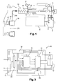
- the transmission system 3 is a simple clutch.
- the actuator 2 comprises in this example a housing 4 cooperating with the housing of an electric machine 6.
- the housing can be attached to the powertrain or the chassis of a vehicle.
- the housing 4 can receive a reducer 7 driven in rotation by the output shaft 8 of the electric machine 6, and a roto-linear motion transformation system 9.
- the gear 7 here has a fixed transmission ratio.
- the reducer 7 may comprise one or two reduction stages.
- the value of the transmission ratio of the gearbox is in the example considered determined according to the maximum force imposed by the transmission system 3 on the actuator 2, so as to reduce the electromagnetic torque to be applied to the rotor of the machine 6 when it maintains the transmission system 3 in a given state.
- the housing 4 also contains in the example considered an electronic card 10 for controlling the operation of the electric machine 6 so that the actuator 2 can have at least two distinct modes of operation.
- this command consists in modifying the torque constant of the electric machine 6 so that it can take at least two distinct values.
- a connector 11 is also carried by the housing 4, to allow the electrical connection of the electronic card 10 to a source of electrical energy which is for example the battery of the onboard network of the vehicle.
- the connector 11 may also allow the electronic card 10 to be connected to the vehicle's CAN (Controller Area Network) bus.
- the control of the electric machine 6 is thus allowed from the engine control unit (ECU) of the vehicle, the latter including implementing a monitoring software of the transmission system 3.
- ECU Engine control unit
- the housing can also receive a position sensor 12 of a movable element of the actuator 2, for example a rotor position sensor of the electric machine 6.
- This sensor 12 may or may not be carried by the electronic card 10.
- the the processing part of this sensor is for example carried by the card 10 while the measuring part of this sensor 12 is disposed at the rotor of the electric machine 6.
- the roto-linear motion transformation system 9 is for example a ball screw, a nut screw or a planetary bearing screw.
- the system 9 can thus be as described in the application filed by the Applicant on October 2, 2013 in France under the number 13 59544 whose contents are incorporated in this application by reference ..
- the system 9 allows, from rotary movement transmitted by the gear 7, to move in translation a piston 13 of a transmitter cylinder 14 for changing the state of the clutch 3.
- the receiving cylinder 18 of the example comprises an annular piston 20 coaxial with the axis of rotation X of the clutch 3.
- This annular piston 20 is in this example connected to a ball bearing 21 which moves in translation along the axis X the diaphragm of the clutch 3, for example via a fork.
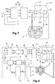
- the figure 3 functionally represents the electronic card 10. As shown in FIG. figure 3 , the electronic card 10 integrates control means of the electric machine 6 and, in the example considered, it cooperates with the sensor 12 which is external to the card 10.
- the card 10 is connected to the connector 11 which, as already mentioned, allows the transmission to the card of both power signals and control signals.
- the card 10 comprises in the example considered a module 30 for managing the power supplies of the card 10.
- This module 30 is electrically powered via the connector 11 by a source of electrical energy of the vehicle, for example the battery of the onboard network .
- the module 30 is, as shown, configured to generate power signals for electrically powering the various components of the card 10, as well as the position sensor 12 of the rotor of the electric machine 6.
- the card 10 may further comprise, as shown on the figure 3 , a static converter 31, a control system 32 of the static converter 31, a management module 33 of the communication on the CAN bus, and a current sensor 35 in the electrical machine 6.
- the module 30 can generate power signals of different value for these different components 31 to 35.
- the static converter 31 comprises in the example in question three arms 40 connected in parallel, each arm 40 being mounted between a positive DC input 47 and a negative DC input 48 of the static converter 31.
- Each arm 40 comprises two switching cells 41 in series. separated from each other by a midpoint 42, each midpoint 42 allowing the electrical connection of the converter 31 to the electrical circuit of the armature of the electrical machine 6 via a branch 44.
- Each switching cell can form a bidirectional current switch, being for example formed by a field effect transistor.
- the static converter 31 is configured to electrically supply the armature of the electric machine from the electrical power supplied by the power supply management module 30 of the card 10.
- the control system 32 of the static converter 31 comprises for example one or more microcontrollers. This or these microcontrollers are configured to communicate with other elements of the electronic card 10. They are for example configured to receive and process data from the position sensor 12 of the rotor of the electric machine 6. These data are for example transmitted in analogue form or in the form of duty cycle values. The processing of these data by the control system 32 may make it possible to carry out a closed-loop control of the actuator 2, for example in current and / or in position and / or in force.
- the control system 32 can furthermore receive and process data from the current sensor 35 in the electrical machine 6, as well as other possible sensors carried by the card 10, in particular sensors making measurements of the temperature, the voltage, and the voltage. food.
- the control system 32 can still receive and process data from external sensors to the card and whose measurements are routed to the control system 32 via the connector 11 and the management module 33.
- the control system 32 can also receive and process, via the connector 11 and the management module 33, other information relating to the control of the actuator 2, for example from the ECU, which are then decoded by this control system 32.
- the measurements thus conveyed via the connector 11 may comprise input speed measurements of a vehicle gearbox.
- the measurements conveyed via the connector 11 can comprise secondary regime oil temperature measurements or position measurements of a shift lever. speeds.
- the control system 32 can also send data via the management module 33 and the connector 11 to the outside of the electronic card 10.
- control system 32 of the static converter 31 may have analog inputs, logic inputs, analog outputs as well as outputs managing logic signals or duty cycle values for controlling the cells. switch 41 of the static converter 31.
- the management module 33 comprises electronic elements configured to manage the communication on a multiplexed network bus and to transmit information conveyed by the link to the control system 32.
- the electric machine is a DC motor comprising two poles to the stator, each of these poles being formed by a permanent magnet.
- the electrical circuit of the armature which is here the rotor, is connected via a collector 50 and brushes 51 and 52 to the midpoint 42 of each arm 40.
- each blade 51 or 52 allows the connection via a branch 44 at a midpoint 42 of an arm 40.
- the static converter 31 is a DC / DC voltage converter.
- the torque constant K is then not ⁇ not e ⁇ ⁇ 2 ⁇ .
- the invention proposes, according to the first example of implementation of the invention, to add a third brush 53 and a third arm 40 to the static converter 31.
- the latter is then in the form of three half-decks in H.
- the addition of a Third brush 53 makes it possible to vary the number of turns of the electrical circuit of the rotor traversed by the electric current I between two midpoints 42 of the static converter 31.
- the first 51 and the second brushes 52 are here arranged in the same way as the two brushes described with reference to the Figures 4a and 4b that is to say that when the current I flows between the first 51 and the second blade 52 in the electric circuit of the rotor, this current flows through all the turns of this electric circuit.
- the third blade 53 is arranged such that when the current I flows between the third blade 53 and one of the first blade 51 and the second blade 52 in the electric circuit of the rotor, this current travels only a part of the turns of the electrical circuit of the rotor.
- the current supplying the electric winding of the rotor is conveyed by the third brush 53, so that the constant can be modified.
- torque K of the electric machine 6 by changing the number of turns traveled in the electrical circuit of the rotor by this current.
- the torque constant K is then higher when the static converter 31 is controlled so that the current flows in the electrical circuit of the rotor between the first 51 and the second blade 52 when the flow of current in the electrical circuit of the rotor involves the third broom 53.
- the third brush 53 is arranged so that, when it cooperates with the collector 50 of the DC machine 6, the current I flowing between the third 53 and the first brush 51 in the
- the electrical circuit of the rotor travels a number of turns equal to that it travels when it flows between the third 53 and the second blade 52 in the electrical circuit of the rotor.
- the number of turns traversed by the current when the third brush 53 conveys said current is here equal to half the total number of turns in the electrical circuit of the rotor which is traversed by the current I between the first 51 and the second 52 brush.
- the curves 111 and 121 reflect the existence in this case of a second value of torque constant lower than the high value of the torque constant of the case of the figure 4 .
- the curves 111 and 121 correspond to a transient operating mode of the actuator 2.
- the third blade 53 is arranged in such a way that the current I flowing between the third 53 and the first blade 51 in the electric circuit of the rotor travels a first number n 1 of turns different from a second one. number n 2 of turns it travels as it travels between the third 53 and the second 52 broom in said electrical circuit.
- the first number n 1 of turns is for example greater than the number n 2 of turns.
- the first number n 1 is for example equal to 2/3 of the total number of turns of the electrical winding of the rotor as the current flows between the first 51 and the second blade 52, while the second number n 2 is equal to 1 / 3 of said total number of turns.
- the values n 1 and n 2 respectively correspond to two low values of torque constant K, one being smaller than the other.
- curves 130, 131 and 132 representing the speed of the machine as a function of the torque T
- curves 140, 141 and 142 representing the current flowing through the electrical circuit of the rotor as a function of the torque T.
- Curves 130 and 140 which correspond to the control of the static converter 31 so that the electric current flowing through the electrical circuit of the rotor flows between the first 51 and the second blade 52, are respectively identical to the curves 100 and 101 of the figure 4b .
- These curves correspond to a control of the electric machine so that the actuator 2 is in an operating mode in which it maintains the transmission system 3 in state or in which it moves slowly.
- the curves 131 and 141 reflect the existence in this case of a first low torque constant value, while the curves 132 and 142 reflect the existence of a second value of low torque constant. These two pairs of curves correspond to configurations in which the actuator 2 moves rapidly, transiently.
- the figure 7 represents the control system 32, the static converter 31, and the dc machine of the example of the figure 5 or the example of the figure 6 .
- the control system 32 here comprises a control circuit 60 generating for certain switching cells 41 a voltage level to be applied to said cell, so as to modify the current path in the electric circuit of the rotor.
- This control circuit 60 receives, as input, duty cycle values, the identification of the switching cells 41 to be controlled, and, if necessary, the desired direction for the displacement of the actuator 2. On the basis of these inputs, the control circuit 60 determines the voltage levels to be applied to the switching cells 41 concerned.
- a quadruple of switching cells 41 that is to say the switching cells 41 of two of the arms 40, is controlled to obtain the desired operating mode of the actuator 2. For example, it would be desirable for the actuator 2 to move, thereby controlling the switching cells 41 surrounding the midpoint 42 connected to the third brush 53 and the switching cells surrounding one of the midpoint 42 connected to the first brush 51 and the point middle 42 surrounding the second broom 42.
- the current controller 61 On the basis of these inputs, the current controller 61 generates the setpoints for the control circuit 60.
- the electric machine 6 is a synchronous machine which is here with permanent magnet rotor.
- the static converter 31 is here a three-phase inverter, each arm 40 being associated with the control of a phase of the electrical circuit of the armature, which is here the stator.
- the control system 32 is configured to apply to the static converter 31 a vector control.
- a vector control For this, the Clarke and Park transforms, known to those skilled in the art, are used.
- the control system 32 interacts here with the position sensor 12, which is in the example considered a Hall effect sensor, and with the current sensor 35 which makes it possible to determine the value of the current in two of the phases of the electrical circuit of the stator.
- the three-phase system is here balanced, we can deduce the value of the current in the last phase of the electric circuit of the stator, so that we know the value of the current in each phase of the stator.
- control system 32 is configured to receive and process the data from these sensors 12 and 35.
- the control system 32 comprises an observer 70 with unknown input, receiving the values transmitted by the Hall effect sensor.
- the output of this observer 70 is a precise measurement of the electric angle of the rotor.
- the Clarke transformer is applied via a block 71 to the current in each phase of the electrical machine 6, and the outputs of this block 72 are received at the input of a block 73 which, using the value of the angle Electrical rotor provided by the observer 70, applies to these outputs the Park transform.
- the components in the Park reference frame of the current I flowing in the electrical winding of the stator are then received at the input of a current controller 75 which also receives as input a setpoint value for the internal angle ⁇ of the machine and a value I sp of current setpoint in the electric circuit of the stator, for example conveyed via the CAN link.
- the current controller 75 determines the components U d and Uq in the Park reference frame of the control voltage of the electric machine 6.
- the control voltage thus determined by this current controller aims to vary the internal angle ⁇ of the machine. Since the torque constant K is in this example equal to 3 2 ⁇ P ⁇ ⁇ ⁇ sin ⁇ , by varying the value of this internal angle, that is by defluxing the synchronous machine 6, the value of the torque constant of the machine 6 is varied, and therefore the value of this constant can be chosen. better suited to the desired operating mode of the actuator 2.
- the inverter 31 is controlled so that the internal angle ⁇ has a value of 90 ° when it is desired to maintain or slowly move the actuator, and the inverter 31 is controlled in such a way that to reduce the value of this internal angle when it is desired to obtain a rapid displacement of the actuator 2.
- Two blocks 81 and 82 successively apply to this control voltage the inverse transforms of Park and Clarke to obtain the control voltages of each phase of the electric machine 6.
- a control circuit 83 generates on the basis of these control voltages. the duty cycle values to be applied to the switching cells of the inverter 31 so as to apply these control voltages to each phase of the electric machine.
- the control system 32 of the exemplary embodiments of the invention described above can be configured to apply an auxiliary command when a failure occurs.
- This failure may be internal to the actuator 2, or affect the transmission system 3, or more generally affect an element of the propulsion system of the vehicle or more generally affect a vehicle element.
- this auxiliary control consists for example in acting on the switching cells of the static converter 31 so that the switching cell 41 of each arm 40 connecting the midpoint 42 and the positive continuous input 47 of the converter 31 is non-conducting, and that the switching cell 41 of said arm 40 connecting the midpoint 42 and the negative DC input 48 is passing. The electric machine is then disconnected from the source of electrical energy.
- the auxiliary command consists, for example, in disabling all of the switching cells 41 of the static converter 31.
- the method may comprise a step 90 of initialization of the actuator 2. This step may make it possible to determine the initial electrical angle of the rotor of the electric machine 6.
- this step may consist of applying an arbitrary voltage to the stator of the machine 6 to orient the rotor in a preferred direction and to set the observer 70 to zero.
- the actuator may be deactivated, the power supply then being interrupted.
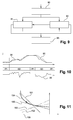
- the figure 10 represents on the one hand on a curve 94 the set value for the position of the actuator 92 as determined for example by the engine control unit of the vehicle, and on a curve 95 the actual position of this actuator 2.
- the fact that the torque constant K has a high value during the steps 91 allows a reduced power consumption, while the fact that this torque constant K has at least a low value during the steps 92 allows rapid movement of the actuator 2 to respond to the instructions satisfactorily.
- the curves 150 and 152, respectively 151 and 153, correspond to the case where the torque constant K has a high value, respectively low.
- the fixed reduction ratio is represented by the line 155.
- the point of intersection between the curves 155 and 154 corresponds to the minimum displacement to be achieved with the gear 7 whose reduction ratio value has been determined as previously mentioned.
- the point of intersection between the curve 152 and the straight line 155 defines the current supplying the electric circuit of the armature when the torque constant K has the high value, while the intersection between the curve 151 and the straight line 155 makes it possible to define the number of revolutions of the electric machine 6 when the torque constant K has the low value, this number of revolutions being performed for a duration corresponding to the desired travel time on the output stroke of the actuator 2.
- the doublet formed by the curves 150 and 152 does not allow the actuator 2 to follow the imposed instruction but allows to consume only a reduced current.
- the control system 32 to obtain this value for the torque constant is thus particularly suitable for an operating mode of the actuator 2 corresponding to a maintenance of the transmission system 3 in a given state or a slow movement of the actuator 2.
- the doublet formed by the curves 151 and 153 allows the actuator 2 to follow the imposed instruction but requires a significant current consumption by the electric machine 6.
- the control system 32 to obtain this value for the torque constant is thus particularly adapted to a transient operating mode of the actuator 2 corresponding to a rapid displacement of the actuator 2.
- the actuator 2 thus has two distinct modes of operation despite the fact that the gear 7 has a fixed value ratio.
- the actuator and the transmission system according to the invention may form an assembly intended to be interposed between a vehicle propulsion heat engine and the vehicle gearbox.
- this assembly is intended to be interposed between a vehicle propulsion engine and a gearbox associated with a rotating electrical machine.
- two sets each comprising the actuator according to the invention and the transmission system may be used, one of the sets being for example disposed on the heat engine side and the other set being disposed on the gearbox side.
- the two sets can be associated with an electric propulsion motor, for example a rotating electrical machine.
- the transmission system on the thermal engine side then makes it possible to couple or uncouple in rotation the crankshaft of the heat engine to the rotor of the rotating electrical machine.
- the transmission system on the gearbox side then makes it possible to couple or uncouple the rotor of the rotating electrical machine to an input shaft of the gearbox.
Description
La présente invention concerne un actionneur électrique pour système de transmission de véhicule.The present invention relates to an electric actuator for a vehicle transmission system.
L'invention s'applique notamment, mais non exclusivement, à l'actionnement d'un embrayage simple ou double dont l'état au repos peut être normalement embrayé ou normalement débrayé, à l'actionnement d'un synchroniseur de boîte de vitesses pour transmission manuelle, à l'actionnement d'une boîte de vitesses robotisée, à l'actionnement d'une boîte de vitesses manuelle à double embrayage, ou encore à l'actionnement d'un embrayage de couplage d'un moteur thermique avec une machine électrique lorsque ces deux derniers font partie d'une chaîne de propulsion d'un véhicule hybride.The invention applies particularly, but not exclusively, to the actuation of a single or double clutch whose idle state can be normally engaged or normally disengaged, the actuation of a gearbox synchronizer for manual transmission, when actuating a robotized gearbox, the actuation of a manual gearbox with a double clutch, or the actuation of a coupling clutch of a heat engine with a machine when the latter two are part of a propulsion system of a hybrid vehicle.
Un tel système de transmission est supposé avoir plusieurs configurations : une configuration dans laquelle il permet la transmission d'un mouvement, c'est-à-dire qu'il est dans l'état embrayé, et une configuration dans laquelle cette transmission ne s'effectue pas, c'est-à-dire qu'il est dans l'état débrayé. L'actionneur électrique permet alors, via un moteur électrique, le maintien du système de transmission dans l'une au moins de ces configurations et le passage de l'une à l'autre de ces configurations.Such a transmission system is supposed to have several configurations: a configuration in which it allows the transmission of a movement, that is to say that it is in the engaged state, and a configuration in which this transmission does not occur. does not perform, that is to say it is in the disengaged state. The electric actuator then allows, via an electric motor, the maintenance of the transmission system in at least one of these configurations and the transition from one to the other of these configurations.
Le maintien par l'actionneur du système de transmission dans une configuration nécessite l'exercice par ce dernier d'un couple de maintien sur le système de transmission, et l'exercice de ce couple est lié à l'alimentation électrique du moteur de l'actionneur par un courant de maintien. Pour réduire la taille de la source d'énergie électrique dédiée à l'alimentation électrique du moteur, il importe que ce courant de maintien soit peu élevé. En outre, ce courant de maintien étant susceptible de générer par effet Joule un échauffement dans le moteur, la réduction de ce courant permet de réduire les risques d'usure prématurée de l'actionneur, voire de destruction par incendie de ce dernier. Ce courant de maintien I pouvant être lié par une constante K au couple électromagnétique T exercé sur le moteur électrique selon la relation T=K*I, cela impose de dimensionner le moteur de sorte que la constante K ait une valeur élevée.The actuator maintains the transmission system in a configuration requires the exercise by the latter of a holding torque on the transmission system, and the exercise of this torque is related to the power supply of the engine of the transmission. actuator by a holding current. To reduce the size of the electrical power source dedicated to the power supply of the motor, it is important that this holding current is low. In addition, this holding current is likely to generate by Joule effect heating in the engine, the reduction of this current reduces the risk of premature wear of the actuator, or even destruction by fire of the latter. Since this holding current I can be linked by a constant K to the electromagnetic torque T exerted on the electric motor according to the relation T = K * I, this makes it necessary to size the motor so that the constant K has a high value.
Le passage du système de transmission de l'une à l'autre des configurations ci-dessus doit être effectué rapidement afin de répondre de façon satisfaisante à une consigne. Pour obtenir une telle rapidité, le moteur doit permettre d'obtenir des vitesses élevées, ce qui nécessite une constante K de valeur peu élevée.The passage of the transmission system from one to the other of the above configurations must be carried out quickly in order to respond satisfactorily to a set point. To obtain such rapidity, the motor must allow to obtain high speeds, which requires a constant K of low value.
L'obtention d'un actionneur électrique permettant de réduire le courant de maintien tout en répondant de façon satisfaisante aux consignes dynamiques suppose ainsi le respect d'exigences contradictoires.Obtaining an electric actuator to reduce the holding current while responding satisfactorily to the dynamic instructions and assumes the fulfillment of conflicting requirements.
Dans ce but, il est connu d'associer un moteur électrique de petite taille avec un réducteur de rapport variable mécaniquement pour adapter la vitesse et le courant du moteur électrique en fonction des consignes, et avec un système de rattrapage d'usure du système de transmission. Il est par ailleurs connu d'associer un moteur électrique de petite taille avec un réducteur de rapport fixe, avec un système élastique fournissant ponctuellement au moteur l'effort nécessaire, et avec un système de rattrapage d'usure du système de transmission.For this purpose, it is known to associate a small electric motor with a gearbox mechanically variable to adapt the speed and current of the electric motor in according to the instructions, and with a wear-compensating system of the transmission system. It is also known to associate a small electric motor with a fixed ratio reducer, with an elastic system occasionally providing the engine with the necessary effort, and with a wear compensating system of the transmission system.
De telles solutions sont complexes à réaliser et nécessitent l'ajout de pièces spécifiques dont un système de rattrapage d'usure du système de transmission, étant en conséquence coûteuses et encombrantes.Such solutions are complex to achieve and require the addition of specific parts including a wear-compensating system of the transmission system, being consequently expensive and cumbersome.
- une machine électrique comprenant un induit et un inducteur,
- un convertisseur statique comprenant une pluralité de cellules de commutation, le convertisseur statique étant disposé de manière à relier électriquement le circuit électrique de l'induit à une source d'énergie électrique, et
- un système de commande des cellules de commutation du convertisseur statique.
- an electric machine comprising an armature and an inductor,
- a static converter comprising a plurality of switching cells, the static converter being arranged to electrically connect the electrical circuit of the armature to a source of electrical energy, and
- a control system of the switching cells of the static converter.
L'invention vise à permettre de bénéficier d'un actionneur électrique pour système de transmission qui permette de concilier les exigences mentionnées précédemment tout en remédiant aux inconvénients des solutions connues.The aim of the invention is to make it possible to benefit from an electric actuator for a transmission system which makes it possible to reconcile the aforementioned requirements while overcoming the drawbacks of known solutions.
L'invention y parvient, selon l'un de ses aspects, à l'aide d'un actionneur pour système de transmission de véhicule, comprenant :
- une machine électrique comprenant un induit et un inducteur, la machine étant telle que la relation entre une grandeur représentative du couple électromagnétique T exercé sur la machine et une grandeur représentative du courant I circulant dans le circuit électrique de l'induit fasse intervenir une constante K, K étant la constante de couple de la machine électrique,
- un convertisseur statique comprenant une pluralité de cellules de commutation, le convertisseur statique étant disposé de manière à relier électriquement le circuit électrique de l'induit à une source d'énergie électrique, et
- un système de commande des cellules de commutation du convertisseur statique, ledit système étant configuré de manière que la constante de couple K de la machine électrique puisse prendre au moins deux valeurs distinctes selon la commande appliquée auxdites cellules.
- an electric machine comprising an armature and an inductor, the machine being such that the relation between a quantity representative of the electromagnetic torque T exerted on the machine and a quantity representative of the current I flowing in the electrical circuit of the armature involves a constant K K being the torque constant of the electric machine,
- a static converter comprising a plurality of switching cells, the static converter being arranged to electrically connect the electrical circuit of the armature to a source of electrical energy, and
- a control system of the switching cells of the static converter, said system being configured such that the torque constant K of the electrical machine can take at least two distinct values according to the command applied to said cells.
Dans le cas d'une machine synchro réluctante le couple électromagnétique est alors proportionnel au courant élevé au carré, l'invention reste valide et applicable même dans ce cas là.In the case of a reluctant synchro machine the electromagnetic torque is then proportional to the current squared, the invention remains valid and applicable even in this case.
La relation ci-dessus peut être une relation linéaire ou affine entre le couple électromagnétique T exercé sur la machine et le courant I circulant dans le circuit électrique de l'induit, par exemple dans le cas où la machine électrique est une machine à courant continu comme on le verra par la suite. La relation s'exprime alors
T = K × I + T 0 où T0 est nul, le cas échéant.The above relationship may be a linear or affine relationship between the electromagnetic torque T exerted on the machine and the current I flowing in the electrical circuit of the armature, for example in the case where the electric machine is a dc machine. as we will see later. The relationship is expressed then
T = K × I + T 0 where T 0 is zero, if any.
En variante, la relation ci-dessus peut être une relation linéaire ou affine entre le couple électromagnétique T exercé sur la machine et un courant I', image par une ou plusieurs transformées mathématiques, par exemple de Clarke et de Park, du courant I circulant dans le circuit électrique de l'induit, par exemple dans le cas où la machine électrique est une machine synchrone, comme on le verra par la suite.Alternatively, the above relationship may be a linear or affine relationship between the electromagnetic torque T exerted on the machine and a current I ', image by one or more mathematical transforms, for example of Clarke and Park, of the circulating current I in the electrical circuit of the armature, for example in the case where the electric machine is a synchronous machine, as will be seen later.
La relation s'exprime alors
T = K × I' + T 0' où T0' est nul, le cas échéant.The relationship is expressed then
T = K × I '+ T 0 ' where T 0 'is zero, if any.
En variante encore, la relation ci-dessus peut être une relation carrée entre le couple électromagnétique T exercé sur la machine et le courant I circulant dans le circuit électrique de l'induit, par exemple dans le cas où la machine électrique est une machine synchro-reluctante, comme on le verra par la suite.As a further variant, the above relationship may be a square relationship between the electromagnetic torque T exerted on the machine and the current I flowing in the electric circuit of the armature, for example in the case where the electric machine is a synchro machine. -reluctante, as we will see later.
La relation s'exprime alors
- T = K × I 2 + T 0 " où T0" est nul, le cas échéant.
- T = K × I 2 + T 0 " where T 0 " is zero, if any.
Chaque valeur de la constante de couple peut correspondre à un mode de fonctionnement différent de l'actionneur. Le passage de l'un à l'autre de ces modes de fonctionnement s'obtient alors en modifiant la commande des cellules de commutation. Autrement dit, contrairement aux solutions selon l'art antérieur, la possibilité pour l'actionneur d'avoir au moins deux modes de fonctionnement différents ne nécessite pas le recours à une architecture matérielle complexe et l'utilisation sélective de certains des éléments de cette architecture selon le mode de fonctionnement souhaité pour l'actionneur. Une seule et même architecture matérielle dont on modifie lorsque nécessaire la commande permet selon l'invention de bénéficier d'un actionneur à au moins deux modes de fonctionnement distincts.Each value of the torque constant may correspond to a mode of operation different from the actuator. The transition from one to the other of these modes of operation is then obtained by modifying the control of the switching cells. In other words, unlike the solutions according to the prior art, the possibility for the actuator to have at least two different modes of operation does not require the use of a complex hardware architecture and the selective use of some of the elements of this architecture according to the desired operating mode for the actuator. One and the same hardware architecture which is modified when necessary control allows according to the invention to benefit from an actuator with at least two distinct modes of operation.
Le système de commande peut être configuré de manière à ce que la constante de couple K de la machine électrique ait une valeur élevée, de manière à permettre de réduire la valeur du courant alimentant la machine électrique, sans pour autant affecter la valeur du couple exercé par l'actionneur sur le système de transmission. Cette valeur élevée convient par exemple pour maintenir en état le système de transmission ou pour déplacer lentement l'actionneur.The control system can be configured such that the torque constant K of the electric machine has a high value, so as to reduce the value of the current supplying the electric machine, without affecting the value of the torque exerted by the actuator on the transmission system. This high value is suitable for example to maintain the transmission system in state or to slowly move the actuator.
L'actionneur peut comprendre un réducteur et ce dernier peut présenter un rapport de réduction fixe, choisi en fonction de l'effort maximal imposé par le système de transmission sur l'actionneur, de manière à réduire le couple électromagnétique devant être appliqué au rotor de la machine électrique lorsqu'elle maintient le système de transmission dans un état donné.The actuator may comprise a gearbox and the latter may have a fixed gear ratio, chosen according to the maximum force imposed by the transmission system on the actuator, so as to reduce the electromagnetic torque to be applied to the rotor of the gearbox. the electric machine when it maintains the transmission system in a given state.
Ce rapport fixe de réduction permet avantageusement de réaliser le compromis entre :
- la réduction la plus important possible de la valeur du couple électromagnétique correspondant à l'effort maximal imposé par le système de transmission et mentionné ci-dessus, et
- une course ou un nombre de révolutions minimal permettant de parcourir la course d'actionnement de l'actionneur de sa position de repos vers une position où il maintient le système de transmission dans l'état donné en un temps qui soit le plus faible possible.
- the largest possible reduction in the value of the electromagnetic torque corresponding to the maximum force imposed by the transmission system and mentioned above, and
- a minimum stroke or number of revolutions enabling the actuator actuation stroke to be traversed from its rest position to a position where it maintains the transmission system in the given state in as short a time as possible.
Cette valeur fixe pour le rapport de réduction permet par exemple de réduire de 25 % à 50% la valeur du couple électromagnétique permettant ledit maintien par rapport à la valeur de couple électromagnétique à fournir par l'actionneur avec un réducteur permettant de réaliser le déplacement de l'actionneur de sa position de repos jusqu'à la position de maintien dans un temps imparti situé par exemple entre 80 et 150ms pour un embrayage entre 30 et 60ms pour un actionneur pour synchroniseur. Avec un tel réducteur, on peut encore diminuer la valeur du courant nécessaire lorsque l'actionneur est dans ce mode de fonctionnement. En effet, la valeur de couple que doit exercer l'actionneur étant réduite, pour une même valeur élevée de la constante de couple K, la valeur du courant alimentant la machine électrique est encore réduite. Ainsi, la valeur du courant prélevé sur une source d'énergie électrique est abaissée de manière significative. La valeur élevée de la constante de couple K, associée à la valeur du rapport de réduction du réducteur, peut permettre de ne prélever pour l'alimentation de la machine électrique qu'un courant de 1A à 2A à la source d'énergie électrique, par exemple la batterie du réseau de bord du véhicule.This fixed value for the reduction ratio makes it possible, for example, to reduce by 25% to 50% the value of the electromagnetic torque allowing said holding with respect to the value of electromagnetic torque to be supplied by the actuator with a reduction gear enabling the displacement of the actuator from its rest position to the holding position in an allotted time, for example between 80 and 150 ms for a clutch between 30 and 60 ms for a synchronizer actuator. With such a reducer, it is possible to further reduce the value of the current required when the actuator is in this mode of operation. Indeed, the torque value that must exert the actuator being reduced, for the same high value of the torque constant K, the value of the current supplying the electric machine is further reduced. Thus, the value of the current drawn from a source of electrical energy is lowered significantly. The high value of the torque constant K, associated with the value of the reduction ratio of the gearbox, can make it possible to take for the power supply of the electric machine only a current of 1A to 2A at the source of electrical energy, for example the battery of the on-board vehicle network.
La réduction de 25% à 50% de ladite valeur du couple de maintien par le choix du rapport de réduction entraine néanmoins une démultiplication de la course à parcourir au niveau du moteur pour déplacer l'actionneur de sa position de repos à la position dans laquelle il maintient le système de transmission dans l'état donné. Pour ne pas allonger le temps nécessaire au déplacement selon cette course de l'actionneur, il faudrait une machine électrique capable de tourner deux à quatre fois plus rapidement Le système de commande peut être configuré de manière à ce que la constante de couple K de la machine électrique ait au moins une valeur faible. Cette ou ces valeurs faibles peuvent correspondre à un mode de fonctionnement étant un déplacement rapide de l'actionneur, par exemple pour suivre une variation de consigne. Dans ce mode de fonctionnement de l'actionneur, le courant électrique alimentant la machine électrique est plus important. Ce mode de fonctionnement peut correspondre à un fonctionnement transitoire de l'actionneur.The reduction of 25% to 50% of said value of the holding torque by the choice of the reduction ratio nevertheless leads to a reduction in the travel to be made at the motor to move the actuator from its rest position to the position in which it keeps the transmission system in the given state. In order not to lengthen the time required for this movement of the actuator, it would be necessary to have an electric machine capable of rotating two to four times faster. The control system can be configured so that the torque constant K of the electric machine has at least a low value. This or these low values can correspond to a mode of operation being a rapid movement of the actuator, for example to follow a setpoint variation. In this mode of operation of the actuator, the electric current supplying the electric machine is more important. This operating mode can correspond to a transient operation of the actuator.
Lorsque la valeur fixe du rapport de réduction est choisie comme mentionné ci-dessus, la réduction de 25% à 50% de la valeur du couple de maintien que cette valeur fixe de rapport de réduction entraîne provoque une démultiplication de la course à parcourir au niveau du moteur pour déplacer l'actionneur de sa position de repos à la position dans laquelle il maintient le système de transmission dans l'état donné. Pour ne pas allonger le temps nécessaire au déplacement selon cette course de l'actionneur, il faudrait une machine électrique capable de tourner deux à quatre fois plus rapidement. La commande des cellules de commutation de manière à ce que la constante de couple prenne la valeur faible, en permettant de faire tourner le moteur deux à quatre fois plus vite qu'avec la valeur élevée, permet de régler ce problème.When the fixed value of the reduction ratio is chosen as mentioned above, the reduction of 25% to 50% of the value of the holding torque that this fixed value of reduction ratio causes causes a reduction in the amount of travel to be made at motor to move the actuator from its rest position to the position in which it maintains the transmission system in the given state. In order not to lengthen the time required for movement according to this stroke of the actuator, an electric machine would have to be able to turn two to four times faster. Controlling the switching cells so that the torque constant takes the low value, allowing the motor to run two to four times faster than the high value, solves this problem.
Le système de commande peut être configuré pour limiter le courant alimentant la machine électrique lors du démarrage de cette dernière, de manière à éviter un échauffement excessif dans la machine électrique ou la démagnétisation d'aimants permanents pouvant être utilisés dans la machine électrique.The control system may be configured to limit the current supplied to the electrical machine when the machine is started, so as to avoid excessive heating in the electric machine or demagnetization of permanent magnets that can be used in the electric machine.
Cette limitation du courant peut être ajustée en fonction de l'état thermique de la machine électrique et de la caractéristique de magnétisation des aimants permanents, cet état thermique pouvant être déterminé à partie d'une mesure de température et/ou à partir d'un modèle de température comme décrit dans le document
Le convertisseur statique peut comprendre trois bras montés en parallèle, chaque bras comprenant deux cellules de commutation en série séparées entre elles par un point milieu, chaque point milieu permettant la connexion électrique du convertisseur au circuit électrique de l'induit.The static converter may comprise three arms mounted in parallel, each arm comprising two switching cells in series separated from each other by a midpoint, each midpoint allowing the electrical connection of the converter to the electrical circuit of the armature.
Selon un premier exemple de mise en oeuvre de l'invention, la machine électrique est une machine à courant continu, ladite machine comprenant trois balais, chaque balai étant relié à un des points milieux du convertisseur statique. La machine électrique peut comprendre uniquement deux pôles au stator.According to a first example of implementation of the invention, the electrical machine is a DC machine, said machine comprising three brushes, each brush being connected to one of the midpoints of the static converter. The electric machine may comprise only two poles to the stator.
Selon ce premier exemple de mise en oeuvre de l'invention, les balais peuvent être disposés de manière à ce que, lorsqu'ils coopèrent avec le collecteur de la machine à courant continu :
- lorsque le courant circule entre le premier et le deuxième balai dans le circuit électrique de l'induit, ledit courant parcourt la totalité des spires du circuit électrique de l'induit, et
- lorsque le courant circule entre le troisième balai et l'un du premier et du deuxième balai dans le circuit électrique de l'induit, ledit courant ne parcourt qu'une partie des spires du circuit électrique de l'induit.
- when the current flows between the first and second brushes in the electric circuit of the armature, said current flows through all the turns of the electric circuit of the armature, and
- when the current flows between the third brush and one of the first and second brushes in the electrical circuit of the armature, said current travels only part of the turns of the electric circuit of the armature.
Ainsi, en commandant le convertisseur statique de manière à ce que le courant circule entre le premier et le deuxième balai dans le circuit électrique de l'induit, ou de manière à ce que cette circulation du courant dans le circuit électrique de l'induit se fasse entre l'un du premier et du deuxième balai et le troisième balai, on modifie le nombre de spires du circuit électrique de l'induit parcourues par ce courant.Thus, by controlling the static converter so that the current flows between the first and the second blade in the electric circuit of the armature, or so that this flow of current in the electrical circuit of the armature is between one of the first and the second broom and the third broom, the number of turns of the electrical circuit of the armature traversed by this current is modified.
Les spires du circuit électrique de l'induit parcourues par le courant électrique lorsqu'il circule entre le premier et le troisième balai peuvent former, avec les spires du circuit électrique de l'induit parcourues par le courant électrique lorsqu'il circule entre le deuxième et le troisième balai, une partition au sens mathématique des spires du circuit électrique de l'induit parcourues par le courant électrique lorsqu'il circule entre le premier et le deuxième balai.The turns of the electric circuit of the armature traversed by the electric current when it circulates between the first and the third blade can form, with the turns of the electrical circuit of the armature traversed by the electric current when it flows between the second and the third broom, a partition in the mathematical sense of the turns of the electrical circuit of the armature traversed by the electric current when it flows between the first and the second broom.
Du fait que la relation entre le couple électromagnétique T exercé sur la machine à courant continu et le courant I circulant dans le circuit électrique de l'induit est ![]()
- n étant le nombre de spires parcourues par le courant électrique dans le circuit électrique de l'induit,
- ne étant le nombre d'encoches du rotor, et
- Φ étant le flux magnétique dans l'entrefer de la machine à courant continu,
- la constante de couple K vaut alors

- where n is the number of turns traveled by the electric current in the electrical circuit of the armature,
- n e is the number of rotor slots, and
- Φ being the magnetic flux in the gap of the dc machine,
- the torque constant K is then worth
Ainsi, selon que le courant électrique circule ou non via le troisième balai, le nombre de spires du circuit électrique de l'induit parcouru par ce courant est modifié, de sorte que la valeur de la constante de couple K est modifiée.Thus, depending on whether or not the electric current flows via the third brush, the number of turns of the electric circuit of the armature traversed by this current is modified, so that the value of the torque constant K is modified.
La constante de couple est ainsi plus élevée lorsque le convertisseur statique est commandé de manière à ce que le courant circule dans le circuit électrique de l'induit entre le premier et le deuxième balai que lorsque la circulation du courant dans le circuit électrique de l'induit fait intervenir le troisième balai.The torque constant is thus higher when the static converter is controlled so that the current flows in the electrical circuit of the armature between the first and the second brush when the flow of current in the electrical circuit of the induced involves the third broom.
Selon un premier sous-exemple de ce premier exemple de mise en oeuvre de l'invention, les balais sont disposés de manière à ce que, lorsqu'ils coopèrent avec le collecteur de la machine à courant continu, le courant circulant entre le troisième et le premier balai dans le circuit électrique de l'induit parcourt un nombre de spires égal à celui qu'il parcourt lorsqu'il circule entre le troisième et le deuxième balai dans le circuit électrique de l'induit.According to a first sub-example of this first example of implementation of the invention, the brushes are arranged so that, when they cooperate with the collector of the DC machine, the current flowing between the third and the first broom in the electrical circuit of the armature travels a number of turns equal to that it travels when it flows between the third and the second broom in the electrical circuit of the armature.
Selon ce premier sous-exemple, le nombre de spires parcourues par le courant électrique dans le circuit électrique de l'induit est ainsi le même dès lors que le troisième balai achemine ce courant, que l'autre balai utilisé pour acheminer le courant dans le circuit électrique de l'induit soit le premier ou le deuxième balai. Dans ce cas, on obtient une première valeur de constante de couple lorsque le convertisseur statique est commandé de manière à ce que le courant circule dans le circuit électrique de l'induit entre le premier et le deuxième balai, et une deuxième valeur de constante de couple, inférieure à la première, lorsque le convertisseur statique est commandé de manière à ce que le courant circule dans le circuit électrique de l'induit entre le premier balai et le troisième balai ou entre le deuxième balai et le troisième balai.According to this first sub-example, the number of turns traversed by the electric current in the electrical circuit of the armature is thus the same when the third broom carries this current, the other broom used to route the current in the electrical circuit of the armature is the first or the second broom. In this case, a first torque constant value is obtained when the static converter is controlled so that the current flows in the electrical circuit of the armature between the first and the second blade, and a second value of constant of torque, less than the first, when the static converter is controlled so that the current flows in the electrical circuit of the armature between the first blade and the third blade or between the second blade and the third blade.
On peut ainsi dans ce cas n'obtenir que deux valeurs possibles pour la constante de couple, de sorte qu'il existe une seule valeur élevée, correspondant au mode de fonctionnement de l'actionneur permettant le maintien en état du système de transmission ou permettant le déplacement lent de l'actionneur, et qu'il n'existe qu'une seule valeur faible, pour le mode de fonctionnement transitoire de l'actionneur.In this case, it is possible to obtain only two possible values for the torque constant, so that there is only one high value corresponding to the operating mode of the actuator making it possible to maintain the transmission system in state or to allow the transmission system to remain in state. the slow movement of the actuator, and that there is only one low value, for the transient operating mode of the actuator.
Ce premier sous-exemple avec seulement deux valeurs distinctes pour la constante de couple de la machine électrique est adapté au cas où le couple que doit exercer l'actionneur pour amener le système de transmission de l'état accouplé à l'état désaccouplé est sensiblement du même ordre que le couple que l'actionneur doit exercer pour amener le système de transmission de l'état désaccouplé à l'état accouplé. C'est par exemple le cas lorsque le système de transmission est un synchroniseur d'une boîte de vitesses.This first sub-example with only two distinct values for the torque constant of the electric machine is adapted to the case where the torque that the actuator must exert to bring the transmission system of the state coupled to the uncoupled state is substantially of the same order as the torque that the actuator must exert to bring the transmission system from the uncoupled state to the coupled state. This is for example the case when the transmission system is a synchronizer of a gearbox.
Selon un deuxième sous-exemple de ce premier exemple de mise en oeuvre de l'invention, les balais sont disposés de manière à ce que, lorsqu'ils coopèrent avec le collecteur de la machine à courant continu, le courant circulant entre le troisième et le premier balai dans le circuit électrique de l'induit parcourt un premier nombre de spires différent d'un deuxième nombre de spires parcourues par ledit courant lorsqu'il circule entre le troisième et le deuxième balai dans le circuit électrique de l'induit.According to a second sub-example of this first example of implementation of the invention, the brushes are arranged so that, when they cooperate with the collector of the DC machine, the current flowing between the third and the first blade in the electrical circuit of the armature travels a first number of turns different from a second number of turns traversed by said current when it flows between the third and the second blade in the electrical circuit of the armature.
Selon ce deuxième sous-exemple, le nombre de spires parcourues par le courant électrique dans le circuit électrique de l'induit est différent lorsque le troisième balai achemine ce courant électrique, selon que l'autre balai utilisé pour acheminer le courant dans le circuit électrique de l'induit est le premier ou le deuxième balai. Le nombre de spires parcourues par le courant électrique dans le circuit électrique de l'induit est par exemple supérieur lorsque le courant circule entre le premier et le troisième balai que lorsque le courant circule entre le deuxième et le troisième balai.According to this second sub-example, the number of turns traveled by the electric current in the electrical circuit of the armature is different when the third blade carries this electric current, depending on whether the other blade used to route the current in the electrical circuit armature is the first or the second broom. The number of turns traveled by the electric current in the electrical circuit of the armature is for example greater when the current flows between the first and the third brush as when the current flows between the second and third brush.
Dans ce cas, on obtient une première valeur de constante de couple lorsque le convertisseur statique est commandé de manière à ce que le courant circule dans le circuit électrique de l'induit entre le premier et le deuxième balai, une deuxième valeur de constante de couple, inférieure à la première, lorsque le convertisseur statique est commandé de manière à ce que le courant circule dans le circuit électrique de l'induit entre le premier balai et le troisième balai, et une troisième valeur de constante de couple, inférieure à la deuxième, lorsque le convertisseur statique est commandé de manière à ce que le courant circule dans le circuit électrique de l'induit entre le deuxième balai et le troisième balai.In this case, a first torque constant value is obtained when the static converter is controlled so that the current flows in the electrical circuit of the armature between the first and the second blade, a second torque constant value. , lower than the first, when the static converter is controlled so that the current flows in the electrical circuit of the armature between the first brush and the third brush, and a third value of torque constant, less than the second , when the static converter is controlled so that the current flows in the electrical circuit of the armature between the second blade and the third blade.
On peut ainsi dans ce cas obtenir trois valeurs possibles pour la constante de couple, de sorte qu'il existe une seule valeur élevée, correspondant au mode de fonctionnement de l'actionneur permettant le maintien en état du système de transmission ou permettant le déplacement lent de l'actionneur, et qu'il existe deux valeurs faibles, pour des modes de fonctionnement transitoires différents.It is thus possible in this case to obtain three possible values for the torque constant, so that there is only one high value, corresponding to the operating mode of the actuator making it possible to maintain the transmission system in state or to allow slow movement. of the actuator, and that there are two weak values, for different transient modes of operation.
On positionne par exemple le troisième balai afin que, lorsque le convertisseur statique est commandé de manière à ce que le courant circule dans le circuit électrique de l'induit entre le premier balai et le troisième balai, le nombre de spires parcourues par le courant électrique soit égal à 2/3 du nombre de spires du circuit électrique de l'induit parcouru par le courant lorsqu'il circule entre le premier et le deuxième balai. Le troisième balai est également positionné de telle sorte que, lorsque le convertisseur statique est commandé de manière à ce que le courant circule dans le circuit électrique entre le deuxième balai et le troisième balai, le nombre de spires parcourues par le courant électrique soit égal à 1/3 du nombre de spires du circuit électrique de l'induit parcouru par le courant lorsqu'il circule entre le premier et le deuxième balai.For example, the third blade is positioned so that, when the static converter is controlled so that the current flows in the electrical circuit of the armature between the first blade and the third blade, the number of turns traversed by the electric current is equal to 2/3 of the number of turns of the electrical circuit of the armature traversed by the current when it flows between the first and the second blade. The third broom is also positioned such so that when the static converter is controlled so that the current flows in the electrical circuit between the second brush and the third brush, the number of turns traversed by the electric current is equal to 1/3 of the number of turns of the electrical circuit of the armature traversed by the current when it flows between the first and the second blade.
L'existence de trois valeurs distinctes pour la constante de couple de la machine à courant continu peut notamment être avantageuse lorsque le système de transmission est un embrayage simple ou double. En effet, dans un tel cas, les frottements et des phénomènes d'hystérésis ont pour conséquence que le couple que l'actionneur doit fournir n'est pas le même lorsque ce dernier doit amener l'embrayage dans l'état embrayé ou dans l'état débrayé. La possibilité d'obtenir deux valeurs de constante faibles distinctes permet ainsi un comportement dynamique satisfaisant de l'actionneur pour ces deux modes différents.The existence of three distinct values for the torque constant of the DC machine may be particularly advantageous when the transmission system is a single or double clutch. Indeed, in such a case, the friction and hysteresis phenomena have the consequence that the torque that the actuator must provide is not the same when the latter must bring the clutch in the engaged state or in the state disengaged. The possibility of obtaining two distinct low constant values thus allows a satisfactory dynamic behavior of the actuator for these two different modes.
Dans le cas où le système de transmission est un embrayage simple, la deuxième valeur de la constante de couple K peut être utilisée pour amener l'embrayage dans l'état accouplé, tandis que la troisième valeur de la constante de couple K peut être utilisée pour amener l'embrayage dans l'état désaccouplé, et tandis que la première valeur de la constante de couple K peut être utilisée pour maintenir l'embrayage dans l'état désaccouplé.In the case where the transmission system is a single clutch, the second value of the torque constant K can be used to bring the clutch into the coupled state, while the third value of the torque constant K can be used to bring the clutch into the uncoupled state, and while the first value of the torque constant K can be used to keep the clutch in the uncoupled state.
Dans le cas où le système de transmission est un embrayage double, dont l'état au repos est l'état désaccouplé, la deuxième valeur de la constante de couple K, ie la valeur faible la plus grande, peut être utilisée pour amener l'embrayage dans l'état désaccouplé, tandis que la troisième valeur de la constante de couple K, ie la valeur faible la plus petite, peut être utilisée pour amener l'embrayage dans l'état accouplé, et tandis que la première valeur de la constante de couple K peut être utilisée pour maintenir l'embrayage dans l'état accouplé.In the case where the transmission system is a double clutch, whose idle state is the uncoupled state, the second value of the torque constant K, ie the smallest largest value, can be used to bring the clutch in the uncoupled state, while the third value of the torque constant K, ie the smallest small value, can be used to bring the clutch into the coupled state, and while the first value of the constant torque K can be used to keep the clutch in the coupled state.
Selon ce premier exemple de mise en oeuvre de l'invention, le système de commande des cellules de commutation est configuré de manière à permettre au moins :
- de commander les cellules de commutation du convertisseur statique de manière à ce que le courant circulant dans le circuit électrique de l'induit circule également dans le premier balai, le deuxième balai, et une partie des bras aux points milieux desquels sont reliés lesdits balais, et
- de commander les cellules de commutation du convertisseur statique de manière à ce que le courant circulant dans le circuit électrique de l'induit circule également dans le troisième balai et dans l'un du premier et du deuxième balai, et une partie des bras aux points milieux desquels sont reliés lesdits balais.
- to control the switching cells of the static converter so that the current flowing in the electric circuit of the armature also circulates in the first blade, the second blade, and part of the arms at the midpoints of which are connected said brushes, and
- to control the switching cells of the static converter so that the current flowing in the electric circuit of the armature also circulates in the third brush and in one of the first and second brushes, and a part of the arms at the points the media of which are connected said brushes.
L'actionneur peut comprendre un organe de mesure du courant circulant entre le point milieu d'un bras et le balai auquel il est relié, et un organe de mesure du courant circulant entre le point milieu d'un autre bras et le balai auquel il est relié. Ces organes de mesure du courant permettent une commande en boucle fermée des cellules de commutation du convertisseur statique.The actuator may comprise a device for measuring the current flowing between the midpoint of an arm and the brush to which it is connected, and a device for measuring the current flowing between the point middle of another arm and the broom to which it is connected. These current measuring devices allow closed-loop control of the switching cells of the static converter.
Selon un deuxième exemple de mise en oeuvre de l'invention, la machine électrique est une machine synchrone et le convertisseur statique forme un onduleur triphasé. La machine synchrone peut être une machine à rotor à aimants permanents ou une machine à rotor bobiné. Il peut encore s'agit d'une machine à courant continu sans balai (désignée par « BLDC » en anglais). De telles machines sont plus robustes et peuvent présenter des performances supérieures à celles des machines à courant continu.According to a second example of implementation of the invention, the electrical machine is a synchronous machine and the static converter forms a three-phase inverter. The synchronous machine may be a permanent magnet rotor machine or a wound rotor machine. It may still be a brushless direct current machine (designated "BLDC" in English). Such machines are more robust and can perform better than those of DC machines.
Dans une telle machine, la constante de couple K dépend de l'angle interne de la machine, lequel est l'angle défini entre le flux rotorique dans la machine et le flux généré par le champ tournant statorique. Le système de commande des cellules de commutation peut, selon ce deuxième exemple de mise en oeuvre de l'invention, être configuré pour appliquer une commande vectorielle aux cellules de commutation de l'onduleur triphasé, ladite commande permettant que l'angle interne de la machine prenne au moins deux valeurs distinctes.In such a machine, the torque constant K depends on the internal angle of the machine, which is the angle defined between the rotor flow in the machine and the flux generated by the stator rotating field. The control system of the switching cells can, according to this second example of implementation of the invention, be configured to apply a vector control to the switching cells of the three-phase inverter, said command allowing the internal angle of the machine takes at least two distinct values.
En utilisant les transformées de Clarke et de Park, l'équation liant le couple électromagnétique exercé sur le rotor de la machine électrique et le module du vecteur courant dans le repère de Park est : ![]()
- P étant le nombre de paires de pôles du stator de la machine synchrone,
- Φ étant le flux magnétique dans l'entrefer de la machine,
- Ψ étant l'angle interne de la machine, et
- I' étant tel que

- Where P is the number of stator pole pairs of the synchronous machine,
- Φ being the magnetic flux in the gap of the machine,
- Ψ being the internal angle of the machine, and
- I being such that
Ainsi, en commandant le système de commande des cellules de commutation de manière à faire varier la valeur de l'angle interne ψ de la machine synchrone, c'est-à-dire en défluxant cette machine synchrone, on fait varier la valeur de la constante de couple K qui est égale à ![]()
![]()
La valeur élevée de la constante de couple K est par exemple obtenue lorsque l'on commande les cellules de commutation du convertisseur statique de manière à ce que l'angle ψ soit égal à 90°.The high value of the torque constant K is for example obtained when the switching cells of the static converter are controlled so that the angle ψ is equal to 90 °.
Il peut être avantageux que le rapport entre la valeur élevée de la constante de couple et la valeur faible de ladite constante soit égal à 3, par exemple lorsque le système de transmission est un embrayage simple ou double, ou que ce rapport soit égal à 2, par exemple lorsque le système de transmission est une boîte de vitesses. La valeur faible de la constante de couple K est obtenue en commandant les cellules de commutation du convertisseur statique de manière à ce que l'angle interne de la machine soit égal à 19,3°, lorsque l'on souhaite un rapport de 3 entre les valeurs de constante de couple, et que cet angle interne soit égal à 30°, lorsque l'on souhaite un rapport de 2 entre les valeurs de constante de couple.It can be advantageous if the ratio between the high value of the torque constant and the low value of said constant is equal to 3, for example when the transmission system is a single or double clutch, or that this ratio is equal to 2, for example when the transmission system is a gearbox. The low value of the torque constant K is obtained by controlling the switching cells of the static converter so that the internal angle of the machine is equal to 19.3 °, when it is desired a ratio of 3 between the torque constant values, and that this internal angle is equal to 30 °, when it is desired a ratio of 2 between the torque constant values.
Le cas échéant, la commande vectorielle des cellules de commutation du convertisseur statique peut permettre que la constante de couple K prenne exactement deux ou trois, voire plus, valeurs distinctes.If necessary, the vector control of the switching cells of the static converter may allow the torque constant K to take exactly two or three or more distinct values.
Selon ce deuxième exemple de mise en oeuvre de l'invention, l'actionneur peut comprendre un organe de mesure du courant circulant une des phases du stator de la machine synchrone, et un organe de mesure du courant circulant dans une autre des phases dudit stator. Le système triphasé étant équilibré, la connaissance du courant dans deux des phases permet de déterminer l'ensemble des courants statoriques. On peut ainsi réaliser une commande vectorielle en boucle fermée.According to this second example of implementation of the invention, the actuator may comprise a device for measuring the current flowing through one of the phases of the stator of the synchronous machine, and a device for measuring the current flowing in another phase of said stator. . The three-phase system being balanced, the knowledge of the current in two of the phases makes it possible to determine all the stator currents. It is thus possible to achieve a closed-loop vector control.
La machine synchrone peut être associée à trois capteurs à effet Hall disposés à 120°.The synchronous machine can be associated with three Hall effect sensors arranged at 120 °.
Selon les deux exemples de mise en oeuvre de l'invention ci-dessus, le système de commande peut être configuré de manière à appliquer une commande auxiliaire lorsqu'il reçoit une information relative à l'existence d'une défaillance. Cette commande auxiliaire peut agir sur les cellules de commutation du convertisseur statique de manière à ce que la cellule de commutation de chaque bras reliant le point milieu et l'entrée continue positive du convertisseur statique soit non passante, et à ce que la cellule de commutation de chaque bras reliant le point milieu et l'entrée continue négative du convertisseur statique soit passante. La machine électrique est alors déconnectée de la source d'énergie électrique, étant au contraire bouclée sur elle-même. On accroît ainsi la sûreté de l'actionneur puisque le moteur de ce dernier est freiné s'il est entraîné par la charge, comme cela se produit dans le cas où le système de transmission est un embrayage simple avec un état au repos accouplé, et qui est dans l'état désaccouplé lorsque la défaillance se produit. Un décollage brutal non souhaité du véhicule est ainsi évité et/ou minimisé.According to the two exemplary embodiments of the invention above, the control system may be configured to apply an auxiliary command when it receives information relating to the existence of a failure. This auxiliary command can act on the switching cells of the static converter so that the switching cell of each arm connecting the midpoint and the positive DC input of the static converter is non-conducting, and that the switching cell each arm connecting the midpoint and the negative continuous input of the static converter is passing. The electric machine is then disconnected from the source of electrical energy, being on the contrary looped on itself. This increases the safety of the actuator since the motor of the latter is braked if it is driven by the load, as happens in the case where the transmission system is a simple clutch with a coupled idle state, and which is in the uncoupled state when the failure occurs. An undesired brutal takeoff of the vehicle is thus avoided and / or minimized.
Dans le cas par exemple où la défaillance concerne une des cellules de commutation reliant le point milieu d'un bras à l'entrée continue positive du convertisseur statique, cette cellule de commutation étant bloquée en mode passant, la commande auxiliaire peut alors :
- commander les autres cellules de commutation reliant les autres points milieux à l'entrée continue positive du convertisseur de manière à ce qu'elles soient passantes, et
- commander les cellules de commutation reliant les points milieux à l'entrée continue négative du convertisseur statique de manière à ce qu'elles soient non passantes,
- controlling the other switching cells connecting the other midpoints to the positive DC input of the converter so that they are passing, and
- controlling the switching cells connecting the mid-points to the negative continuous input of the static converter so that they are non-conducting,
Lorsque la défaillance concerne une cellule de commutation reliant un point milieu à l'entrée continue négative du convertisseur statique et que cette cellule est bloquée en mode passant, une commande symétrique de celle qui vient d'être décrite peut être appliquée.When the fault concerns a switching cell connecting a midpoint to the negative DC input of the static converter and this cell is blocked in the on mode, a symmetrical control of that just described can be applied.
Lorsque la défaillance concerne une des cellules de commutation et que cette dernière est bloquée à l'état non passant, la commande auxiliaire peut se faire en commandant les cellules de commutation reliées à l'entrée continue du convertisseur statique à laquelle la cellule de commutation victime de la défaillance n'est pas reliée..When the fault concerns one of the switching cells and the latter is blocked in the off state, the auxiliary command can be done by controlling the switching cells connected to the DC input of the static converter to which the victim switching cell of the failure is not connected ..
En variante, et notamment dans le cas où le système de transmission est un double embrayage dont l'état au repos est l'état désaccouplé, la commande auxiliaire peut consister à rendre non passant l'ensemble des cellules de commutation du convertisseur statique, afin d'accélérer le passage du système de transmission dans l'état désaccouplé.As a variant, and especially in the case where the transmission system is a double clutch whose rest state is the uncoupled state, the auxiliary command may consist of making all the switching cells of the static converter turn off, so that to accelerate the passage of the transmission system in the uncoupled state.
Dans tout ce qui précède, la défaillance peut se rapporter à l'actionneur, au système de transmission, plus globalement à la chaîne de propulsion du véhicule, voire même plus globalement au véhicule.In all the foregoing, the failure may relate to the actuator, to the transmission system, more generally to the propulsion system of the vehicle, or even more generally to the vehicle.
Dans tout ce qui précède, lorsque la machine électrique est tournante, l'actionneur peut comprendre un organe de mesure de la position angulaire du rotor de la machine électrique tournante.In all of the above, when the electrical machine is rotating, the actuator may comprise a member for measuring the angular position of the rotor of the rotating electrical machine.
L'invention n'est pas limitée aux exemples de machines électriques mentionnés ci-dessus. Elle s'applique également à des actionneurs pour systèmes de transmission fonctionnant à l'aide d'une machine asynchrone, d'une machine à reluctance variable ou synchro-reluctante, ou d'une machine synchrone auto-pilotée.The invention is not limited to the examples of electrical machines mentioned above. It also applies to actuators for transmission systems operating using an asynchronous machine, a variable reluctance machine or synchro-reluctant, or a self-driven synchronous machine.
L'invention a encore pour objet, selon un autre de ses aspects, un actionneur pour système de transmission de véhicule, comprenant :
- une machine électrique,
- un convertisseur statique comprenant une pluralité de cellules de commutation, le convertisseur statique étant disposé de manière à relier électriquement le circuit électrique de l'induit à une source d'énergie électrique, et
- un système de commande des cellules de commutation du convertisseur statique, ledit système étant configuré de manière à permettre un defluxage de la machine électrique pour que la constante de couple de ladite machine électrique puisse prendre au moins deux valeurs distinctes.
- an electric machine,
- a static converter comprising a plurality of switching cells, the static converter being arranged to electrically connect the electrical circuit of the armature to a source of electrical energy, and
- a control system of the switching cells of the static converter, said system being configured to allow defluxing of the electrical machine so that the torque constant of said electrical machine can take at least two distinct values.
Tout ou partie des caractéristiques mentionnées ci-dessus s'applique à cet autre aspect de l'inventionAll or some of the features mentioned above apply to this other aspect of the invention
L'invention a encore pour objet, selon un autre de ses aspects, un ensemble, comprenant :
- un actionneur tel que défini ci-dessus, et
- un système de transmission de véhicule, ledit système comprenant un organe apte à être déplacé par l'actionneur.
- an actuator as defined above, and
- a vehicle transmission system, said system comprising a member adapted to be moved by the actuator.
L'actionneur peut comprendre un élément d'actionnement configuré pour déplacer ledit organe du système de transmissionThe actuator may include an actuating element configured to move said transmission system member
L'organe apte à être déplacé par l'actionneur peut être un diaphragme d'embrayage ou un cylindre émetteur, par exemple.The member adapted to be moved by the actuator may be a clutch diaphragm or a transmitter cylinder, for example.
Le système de transmission peut être l'un embrayage à sec, d'un double embrayage à sec et d'un synchroniseur de boîte de vitesses.The transmission system can be a dry clutch, a dual dry clutch and a transmission synchronizer.
L'invention a encore pour objet, selon un autre de ses aspects, un procédé de commande d'un actionneur tel que défini ci-dessus, procédé dans lequel la commande des cellules de commutation du convertisseur statique permet que la valeur de la constante de couple prenne au moins une valeur élevée et au moins une valeur faible.According to another of its aspects, the subject of the invention is also a method of controlling an actuator as defined above, in which the control of the switching cells of the static converter allows the value of the constant of couple takes at least one high value and at least one low value.
Le procédé peut comprendre l'étape selon laquelle on commande les cellules de commutation de manière à ce que la constante de couple prenne la valeur élevée lorsque l'actionneur maintient le système de transmission dans un état donné.The method may include the step of controlling the switching cells so that the torque constant takes the high value when the actuator maintains the transmission system in a given state.
Cet état donné peut être l'état accouplé ou dans l'état désaccouplé du système de transmission. Le maintien du système de transmission dans cet état par l'actionneur se traduit pour l'actionneur par le fait que la consigne de position de ce dernier n'évolue plus et par le fait que son déplacement est terminé.This given state may be the coupled state or in the uncoupled state of the transmission system. Maintaining the transmission system in this state by the actuator is reflected for the actuator in that the position of the latter setting no longer evolves and in that its movement is completed.
Lorsque le système de transmission est un embrayage simple ou double dont l'état au repos est l'état accouplé, les cellules de commutation peuvent être commandées de manière à ce que la constante de couple prenne la valeur élevée pour que l'actionneur maintienne le système de transmission dans l'état désaccouplé.When the transmission system is a single or dual clutch whose idle state is the coupled state, the switching cells can be controlled so that the torque constant takes the high value for the actuator to maintain the transmission system in the uncoupled state.
Lorsque le système de transmission est un embrayage simple ou double dont l'état au repos est l'état désaccouplé, les cellules de commutation peuvent être commandées de manière à ce que la constante de couple prenne la valeur élevée pour que l'actionneur maintienne le système de transmission dans l'état accouplé.When the transmission system is a single or dual clutch whose idle state is the uncoupled state, the switching cells can be controlled so that the torque constant takes the high value for the actuator to maintain the transmission system in the coupled state.
Le procédé peut comprendre l'étape selon laquelle on commande les cellules de commutation de manière à ce que la constante de couple prenne la valeur faible pour déplacer l'actionneur. Cette étape peut être effectuée à la réception d'une consigne de déplacement et peut permettre de modifier l'état du système de transmission.The method may include the step of controlling the switch cells such that the torque constant takes the low value to move the actuator. This step can be performed upon receipt of a displacement instruction and can make it possible to modify the state of the transmission system.
Comme mentionné précédemment, le système de commande peut être configuré de manière à ce que la constante de couple puisse prendre une seule valeur élevée et au moins deux, notamment seulement deux, valeurs faibles. Le système de transmission peut être un embrayage, et les cellules de commutation peuvent être commandées de manière à ce que la constante de couple prenne l'une des valeurs faibles pour amener le système de transmission dans l'état désaccouplé et les cellules de commutation peuvent être commandées de manière à ce que la constante de couple prenne l'autre des valeurs faibles pour amener le système de transmission dans l'état accouplé.As mentioned previously, the control system can be configured so that the torque constant can take a single high value and at least two, especially only two, low values. The transmission system can be a clutch, and the switching cells can be controlled in such a way that the torque constant take one of the low values to bring the transmission system into the uncoupled state and the switching cells can be controlled in such a way that the torque constant takes the other of the low values to bring the transmission system into the coupled state.
Dans le cas où le système de transmission est un embrayage simple dont l'état au repos est l'état accouplé, la valeur faible la plus grande de la constante de couple peut être utilisée pour amener l'embrayage dans l'état accouplé, tandis que la valeur faible la plus petite de la constante de couple peut être utilisée pour amener l'embrayage dans l'état désaccouplé.In the case where the transmission system is a single clutch whose idle state is the coupled state, the largest low value of the torque constant can be used to bring the clutch into the coupled state, while that the smallest small value of the torque constant can be used to bring the clutch into the uncoupled state.
Dans le cas où le système de transmission est un embrayage double, la valeur faible la plus grande de la constante de couple peut être utilisée pour amener l'embrayage dans l'état désaccouplé, tandis que la valeur faible la plus petite de la constante de couple peut être utilisée pour amener l'embrayage dans l'état accouplé.In the case where the transmission system is a double clutch, the largest low value of the torque constant can be used to bring the clutch into the uncoupled state, while the smallest value of the constant of the torque can be used to bring the clutch into the coupled state.
Comme mentionné précédemment, le système de commande peut être configuré de manière à ce que la constante de couple puisse prendre une seule valeur élevée et une seule valeur faible. C'est par exemple le cas où le système de transmission est un synchroniseur de boîte de vitesses, auquel cas la commande des cellules de commutation de manière à ce que la constante de couple prenne la valeur élevée peut correspondre à la phase de synchronisation dudit synchroniseur. Cette phase peut consister à synchroniser les vitesses en amont et en aval dudit synchroniseur.As mentioned previously, the control system can be configured so that the torque constant can take a single high value and a single low value. This is for example the case where the transmission system is a gearbox synchronizer, in which case the control of the switching cells so that the torque constant takes the high value can correspond to the synchronization phase of said synchronizer . This phase may consist of synchronizing the speeds upstream and downstream of said synchronizer.
Toujours lorsque le système de transmission est un synchroniseur de boîte de vitesses, la commande des cellules de commutation de manière à ce que la constante de couple prenne la valeur faible peut correspondre aux phases de déplacement hors phase de synchronisation dudit synchroniseur.Still when the transmission system is a transmission synchronizer, the control of the switching cells so that the torque constant takes the low value can correspond to the phases of out of phase synchronization of said synchronizer.
Selon le procédé ci-dessus, le système de commande peut être configuré de manière à appliquer une commande auxiliaire aux cellules de commutation lorsque ce système de commande reçoit une information relative à l'existence d'une défaillance.According to the above method, the control system may be configured to apply auxiliary control to the switching cells when the control system receives information relating to the existence of a failure.
Le système de transmission est par exemple un embrayage simple ou double, dont l'état au repos est l'état accouplé, la commande auxiliaire peut agir sur les cellules de commutation du convertisseur statique de manière à ce que :
- la cellule de commutation de chaque bras reliant le point milieu et l'entrée continue positive, respectivement négative, du convertisseur statique soit non passante, et
- la cellule de commutation de chaque bras reliant le point milieu et l'entrée continue négative, respectivement positive, du convertisseur statique soit passante, de manière à freiner la machine électrique lorsqu'elle est entraînée par la charge du système de transmission.
- the switching cell of each arm connecting the mid-point and the positive continuous input, respectively negative, of the static converter is non-conducting, and
- the switching cell of each arm connecting the mid-point and the negative continuous input, respectively positive, of the static converter is passing, so as to brake the electric machine when it is driven by the load of the transmission system.
En variante, le système de transmission est un embrayage simple ou double, dont l'état au repos est l'état désaccouplé, et la commande auxiliaire agit sur les cellules de commutation du convertisseur statique de manière à rendre non passant l'ensemble desdites cellules de commutation du convertisseur statique, afin de ne pas freiner la machine électrique lorsqu'elle est entraînée par la charge du système de transmission.In a variant, the transmission system is a single or double clutch, whose rest state is the uncoupled state, and the auxiliary control acts on the switching cells of the static converter so as to make all of said cells non-passing. of switching of the static converter, so as not to brake the electric machine when it is driven by the load of the transmission system.
L'invention pourra être mieux comprise à la lecture d'exemples non limitatifs de mise en oeuvre de celle-ci et à l'examen du dessin annexé sur lequel :
- la
figure 1 est une représentation cinématique d'un ensemble comprenant un actionneur selon un exemple de mise en oeuvre de l'invention et le système de transmission avec lequel il interagit, - la
figure 2 est une vue en élévation de l'ensemble de lafigure 1 , - la
figure 3 représente un exemple de carte électronique utilisée pour la réalisation d'un actionneur selon un exemple de mise en oeuvre de l'invention, - la
figure 4a représente un convertisseur statique permettant l'alimentation électrique d'une machine à courant continu et ladite machine à courant continu selon l'art antérieur, et lafigure 4b est un graphe représentant la vitesse de la machine et le courant alimentant cette dernière, en fonction du couple électromagnétique appliqué sur la machine, - la
figure 5a représente un convertisseur statique permettant l'alimentation électrique d'une machine à courant continu et ladite machine d'un actionneur selon un premier sous-exemple d'un premier exemple de mise en oeuvre de l'invention, et lafigure 5b est un graphe représentant la vitesse de la machine et le courant alimentant cette dernière, en fonction du couple électromagnétique appliqué sur la machine, - la
figure 6a représente un convertisseur statique permettant l'alimentation électrique d'une machine à courant continu et ladite machine d'un actionneur selon un deuxième sous-exemple du premier exemple de mise en oeuvre de l'invention, et lafigure 6b est un graphe représentant la vitesse de la machine et le courant alimentant cette dernière, en fonction du couple électromagnétique appliqué sur la machine, - la
figure 7 complète lafigure 5a ou lafigure 6a en y ajoutant un système de commande du convertisseur statique, - la
figure 8 représente un système de commande, un convertisseur statique et une machine synchrone d'un actionneur selon un deuxième exemple de mise en oeuvre de l'invention, - la
figure 9 représente sous forme de schémas blocs un procédé de commande de l'actionneur selon les deux exemples de mise en oeuvre décrits ci-dessus, - la
figure 10 permet de visualiser simultanément la position de l'actionneur et l'alimentation électrique de la machine électrique de cet actionneur, et - la
figure 11 est un graphe représentant différentes grandeurs illustrant l'effet des premier et deuxième exemples de mise en oeuvre de l'invention.
- the
figure 1 is a kinematic representation of an assembly comprising an actuator according to an exemplary implementation of the invention and the transmission system with which it interacts, - the
figure 2 is an elevation view of the whole of thefigure 1 , - the
figure 3 represents an example of an electronic card used for producing an actuator according to an exemplary implementation of the invention, - the
figure 4a represents a static converter allowing the power supply of a DC machine and said DC machine according to the prior art, and thefigure 4b is a graph representing the speed of the machine and the current supplying it, as a function of the electromagnetic torque applied to the machine, - the
figure 5a represents a static converter allowing the power supply of a DC machine and said machine an actuator according to a first sub-example of a first embodiment of the invention, and thefigure 5b is a graph representing the speed of the machine and the current supplying it, as a function of the electromagnetic torque applied to the machine, - the
figure 6a represents a static converter allowing the power supply of a DC machine and said machine an actuator according to a second sub-example of the first embodiment of the invention, and thefigure 6b is a graph representing the speed of the machine and the current supplying it, as a function of the electromagnetic torque applied to the machine, - the
figure 7 complete thefigure 5a or thefigure 6a by adding a control system of the static converter, - the
figure 8 represents a control system, a static converter and a synchronous machine of an actuator according to a second example of implementation of the invention, - the
figure 9 represents, in the form of block diagrams, a control method of the actuator according to the two implementation examples described above, - the
figure 10 allows to simultaneously view the position of the actuator and the power supply of the electric machine of this actuator, and - the
figure 11 is a graph representing different quantities illustrating the effect of the first and second examples of implementation of the invention.
On a représenté sur la
L'actionneur 2 comprend dans cet exemple un boîtier 4 coopérant avec le carter d'une machine électrique 6. Le boîtier peut être fixé sur le groupe moto-propulseur ou sur le châssis d'un véhicule.The
Le boîtier 4 peut recevoir un réducteur 7 entraîné en rotation par l'arbre de sortie 8 de la machine électrique 6, et un système 9 de transformation de mouvement roto-linéaire. Le réducteur 7 présente ici un rapport de transmission fixe. Le réducteur 7 peut comprendre un ou deux étages de réduction. La valeur du rapport de transmission du réducteur est dans l'exemple considéré déterminée en fonction de l'effort maximal imposé par le système de transmission 3 sur l'actionneur 2, de manière à réduire le couple électromagnétique devant être appliqué au rotor de la machine électrique 6 lorsqu'elle maintient le système de transmission 3 dans un état donné.The housing 4 can receive a
Le boîtier 4 contient aussi dans l'exemple considéré une carte électronique 10 permettant de commander le fonctionnement de la machine électrique 6 de manière à ce que l'actionneur 2 puisse présenter au moins deux modes de fonctionnements distincts. Comme on le verra par la suite, cette commande consiste à modifier la constante de couple de la machine électrique 6 de manière à ce que celle-ci puisse prendre au moins deux valeurs distinctes.The housing 4 also contains in the example considered an
Un connecteur 11 est également porté par le boîtier 4, pour permettre la connexion électrique de la carte électronique 10 à une source d'énergie électrique qui est par exemple la batterie du réseau de bord du véhicule. Le connecteur 11 peut également permettre de connecter la carte électronique 10 au bus CAN (Controller Area Network) du véhicule. On permet ainsi la commande de la machine électrique 6 à partir de l'unité de contrôle moteur (ECU) du véhicule, cette dernière mettant notamment en oeuvre un logiciel de supervision du système de transmission 3.A
Le boîtier peut aussi recevoir un capteur 12 de position d'un élément mobile de l'actionneur 2, par exemple un capteur de position du rotor de la machine électrique 6. Ce capteur 12 peut ou non être porté par la carte électronique 10. La partie de traitement de ce capteur est par exemple portée par la carte 10 tandis que la partie de mesure de ce capteur 12 est disposée au niveau du rotor de la machine électrique 6.The housing can also receive a
Le système 9 de transformation de mouvement roto-linéaire est par exemple une vis à billes, une vis écrou ou une vis à roulements planétaires. Le système 9 peut ainsi être tel que décrit dans la demande déposée par la Demanderesse le 2 octobre 2013 en France sous le numéro 13 59544 dont le contenu est incorporé à la présente demande par référence.. Le système 9 permet, à partir du mouvement rotatif transmis par le réducteur 7, de déplacer en translation un piston 13 d'un cylindre émetteur 14 permettant de modifier l'état de l'embrayage 3.The roto-linear
Le déplacement de ce piston 13 sur une première course, dite course morte, met à découvert un orifice 15 qui relie la chambre 16 du cylindre émetteur 14 à un réservoir hydraulique basse pression 17. Le déplacement du piston 13 sur une deuxième course, dite course active, permet de recouvrir cet orifice, de sorte que le fluide contenu dans la chambre 16 du cylindre émetteur 14 peut être déplacé par le piston 13 vers un cylindre récepteur 18, via une canalisation hydraulique 19. Le cylindre récepteur 18 de l'exemple considéré comprend un piston annulaire 20 coaxial à l'axe de rotation X de l'embrayage 3. Ce piston annulaire 20 est dans l'exemple considéré relié à un roulement à billes 21 qui vient déplacer en translation selon l'axe X le diaphragme de l'embrayage 3, par exemple via une fourchette.The displacement of this
La
La carte 10 est reliée au connecteur 11 qui, comme déjà mentionné, permet l'acheminement à la carte à la fois de signaux de puissance et de signaux de commande.The
La carte 10 comprend dans l'exemple considéré un module 30 de gestion des alimentations électriques de la carte 10. Ce module 30 est électriquement alimenté via le connecteur 11 par une source d'énergie électrique du véhicule, par exemple la batterie du réseau de bord. Le module 30 est, comme représenté, configuré pour générer des signaux de puissance permettant d'alimenter électriquement les différents composants de la carte 10, ainsi que le capteur de position 12 du rotor de la machine électrique 6.The
La carte 10 peut encore comprendre, comme représenté sur la
Le convertisseur statique 31 comprend dans l'exemple considéré trois bras 40 montés en parallèle, chaque bras 40 étant monté entre une entrée continue positive 47 et une entrée continue négative 48 du convertisseur statique 31. Chaque bras 40 comprend deux cellules de commutation 41 en série séparées entre elles par un point milieu 42, chaque point milieu 42 permettant la connexion électrique du convertisseur 31 au circuit électrique de l'induit de la machine électrique 6 via une branche 44. Chaque cellule de commutation peut former un interrupteur bidirectionnel en courant, étant par exemple formée par un transistor à effet de champ.The
Le convertisseur statique 31 est configuré pour alimenter électriquement l'induit de la machine électrique à partir de la puissance électrique fournie par le module 30 de gestion des alimentations électriques de la carte 10.The
Le système de commande 32 du convertisseur statique 31 comprend par exemple un ou plusieurs microcontrôleurs. Ce ou ces microcontrôleurs sont configurés pour communiquer avec d'autres éléments de la carte électronique 10. Ils sont par exemple configurés pour recevoir et traiter des données en provenance du capteur de position 12 du rotor de la machine électrique 6. Ces données sont par exemple transmises sous forme analogique ou sous forme de valeurs de rapport cyclique. Le traitement de ces données par le système de commande 32 peut permettre de réaliser une commande en boucle fermée de l'actionneur 2 par exemple en courant et/ou en position et/ou en effort.The
Le système de commande 32 peut en outre recevoir et traiter des données du capteur 35 du courant dans la machine électrique 6, ainsi que d'autres capteurs éventuels portés par la carte 10, notamment des capteurs effectuant des mesures de température, de tension d'alimentation. Le système de commande 32 peut encore recevoir et traiter des données provenant de capteurs externes à la carte et dont les mesures sont acheminées au système de commande 32 via le connecteur 11 et le module de gestion 33.The
Le système de commande 32 peut également recevoir et traiter, via le connecteur 11 et le module de gestion 33, d'autres informations relatives à la commande de l'actionneur 2, par exemple issues de l'ECU, qui sont alors décodées par ce système de commande 32.The
Dans le cas où l'actionneur 2 interagit avec un embrayage, les mesures ainsi acheminées via le connecteur 11 peuvent comprendre des mesures de vitesse d'entrée d'une boîte de vitesse du véhicule. Dans le cas où l'actionneur 2 est un actionneur de passage ou de sélection de vitesses, les mesures acheminées via le connecteur 11 peuvent comprendre des mesures de température d'huile de régime secondaire ou des mesures de position d'un levier de passage des vitesses.In the case where the
Le système de commande 32 peut également envoyer des données via le module de gestion 33 et le connecteur 11 vers l'extérieur de la carte électronique 10.The
Afin de réaliser les différentes communications ci-dessus, le système de commande 32 du convertisseur statique 31 peut présenter des entrées analogiques, des entrées logiques, des sorties analogiques ainsi que des sorties gérant des signaux logiques ou des valeurs de rapport cyclique pour commander les cellules de commutation 41 du convertisseur statique 31.In order to carry out the various communications above, the
Le module de gestion 33 comprend des éléments électroniques configurés pour gérer la communication sur un bus réseau multiplexé et pour transmettre des informations véhiculées par la liaison au système de commande 32.The
On va maintenant décrire plus précisément en référence aux
Selon ce premier exemple de mise en oeuvre de l'invention, la machine électrique est un moteur à courant continu comprenant deux pôles au stator, chacun de ces pôles étant formé par un aimant permanent. Le circuit électrique de l'induit, qui est ici le rotor, est relié via un collecteur 50 et des balais 51 et 52 au point milieu 42 de chaque bras 40. Plus précisément, chaque balai 51 ou 52 permet la connexion via une branche 44 à un point milieu 42 d'un bras 40. Toujours selon ce premier exemple de mise en oeuvre de l'invention, le convertisseur statique 31 est un convertisseur de tension continu/continu.According to this first example of implementation of the invention, the electric machine is a DC motor comprising two poles to the stator, each of these poles being formed by a permanent magnet. The electrical circuit of the armature, which is here the rotor, is connected via a
Dans l'exemple de la ![]()
- n étant le nombre de spires parcourues par le courant électrique dans le circuit électrique de l'induit,
- ne étant le nombre d'encoches du rotor,
- Φ étant le flux magnétique dans l'entrefer de la machine à courant continu,
- where n is the number of turns traveled by the electric current in the electrical circuit of the armature,
- n e is the number of rotor slots,
- Φ being the magnetic flux in the gap of the dc machine,
La constante de couple K vaut alors ![]()
![]()
Dans le cas où la machine électrique 6 et le convertisseur statique 31 sont tels que représentés sur la
Pour remédier à cet inconvénient, l'invention propose, selon le premier exemple de mise en oeuvre de l'invention, d'ajouter un troisième balai 53 et un troisième bras 40 au convertisseur statique 31. Ce dernier se présente alors sous la forme de trois demi-ponts en H. L'ajout d'un troisième balai 53 permet de faire varier le nombre de spires du circuit électrique du rotor parcourues par le courant électrique I entre deux points milieux 42 du convertisseur statique 31.To remedy this drawback, the invention proposes, according to the first example of implementation of the invention, to add a
Le premier 51 et le deuxième balais 52 sont ici disposés de la même façon que les deux balais décrits en référence aux
Le troisième balai 53 est disposé de telle sorte que lorsque le courant I circule entre le troisième balai 53 et l'un du premier 51 et du deuxième 52 balai dans le circuit électrique du rotor, ce courant ne parcourt qu'une partie des spires du circuit électrique du rotor. Ainsi, selon la commande appliquée par le système de commande 32 aux cellules de commutation 41 du convertisseur statique 31, la courant alimentant l'enroulement électrique du rotor est acheminé par le troisième balai 53, de sorte que l'on peut modifier la constante de couple K de la machine électrique 6 en modifiant le nombre de spires parcourues dans le circuit électrique du rotor par ce courant. La constante de couple K est alors plus élevée lorsque le convertisseur statique 31 est commandé de manière à ce que le courant circule dans le circuit électrique du rotor entre le premier 51 et le deuxième 52 balai que lorsque la circulation du courant dans le circuit électrique du rotor fait intervenir le troisième balai 53.The
On va décrire en référence aux
Comme on peut le voir sur la
Les courbes 111 et 121 traduisent l'existence dans ce cas d'une deuxième valeur de constante de couple plus faible que la valeur élevée de la constante de couple du cas de la
On va maintenant décrire en référence aux
Le premier nombre n1 de spires est par exemple supérieur au nombre n2 de spires. Le premier nombre n1 est par exemple égal à 2/3 du nombre de spires total de l'enroulement électrique du rotor que le courant parcourt entre le premier 51 et le deuxième 52 balai, tandis que le deuxième nombre n2 est égal à 1/3 dudit nombre de spires total. Aux valeurs n1 et n2 correspondent respectivement deux valeurs faibles de constante de couple K, l'une étant plus petite que l'autre.The first number n 1 of turns is for example greater than the number n 2 of turns. The first number n 1 is for example equal to 2/3 of the total number of turns of the electrical winding of the rotor as the current flows between the first 51 and the
Selon ce deuxième sous-exemple, on obtient :
- une valeur élevée de la constante de couple K lorsque le convertisseur statique 31 est commandé de manière à ce que le courant I circule dans le circuit électrique du rotor entre le premier 51 et le deuxième 52 balai,
- une première valeur faible de la constante de couple K lorsque le convertisseur statique 31 est commandé de manière à ce que le courant I circule dans le circuit électrique du rotor entre le
premier balai 51 et le troisième balai 53, et - une deuxième valeur faible de la constante de couple K, plus petite que la première valeur faible, lorsque le convertisseur statique 31 est commandé de manière à ce que le courant I circule dans le circuit électrique du rotor entre le deuxième balai 52 et le troisième balai 53.
- a high value of the torque constant K when the
static converter 31 is controlled so that the current I flows in the electric circuit of the rotor between the first 51 and thesecond blade 52, - a first low value of the torque constant K when the
static converter 31 is controlled so that the current I flows in the electric circuit of the rotor between thefirst blade 51 and thethird blade 53, and - a second low value of the torque constant K, smaller than the first low value, when the
static converter 31 is controlled so that the current I flows in the electrical circuit of the rotor between thesecond blade 52 and thethird blade 53.
On peut ainsi dans ce cas obtenir trois valeurs possibles pour la constante de couple.In this case, it is possible to obtain three possible values for the torque constant.
Comme on peut le voir sur la
Les courbes 131et 141 traduisent l'existence dans ce cas d'une première valeur de constante de couple faible, tandis que les courbes 132 et 142 traduisent l'existence d'une deuxième valeur de constante de couple faible. Ces deux couples de courbe correspondent à des configurations dans lesquelles l'actionneur 2 se déplace rapidement, en transitoire.The
La présence de deux valeurs faibles pour la constante de couple K permet de traiter de façon satisfaisante le cas où le sens de déplacement de l'actionneur 2 impose des contraintes particulières au couple que ce dernier doit exercer sur le système de transmission 3. Chaque valeur faible de la constante de couple K peut alors être dédiée à un sens de déplacement de l'actionneur 2.The presence of two weak values for the torque constant K makes it possible to satisfactorily deal with the case where the direction of movement of the
La
Selon les consignes générées, un quadruplet de cellules de commutation 41, c'est-à-dire les cellules de commutation 41 de deux des bras 40, est commandé pour obtenir le mode de fonctionnement souhaité de l'actionneur 2. Si l'on souhaite par exemple que l'actionneur 2 se déplace, on commandera ainsi les cellules de commutation 41 entourant le point milieu 42 relié au troisième balai 53 et les cellules de commutation entourant l'un du point milieu 42 relié au premier balai 51 et du point milieu 42 entourant le deuxième balai 42.According to the instructions generated, a quadruple of switching
Le système de commande 32 comprend encore dans l'exemple considéré un contrôleur de courant 61 recevant en entrée :
- une consigne de vitesse pour l'actionneur 2,
- une consigne de courant dans le circuit électrique du rotor, et
- les valeurs de courant dans au moins deux
branches 44, mesurées à l'aide du capteur 35 déjà mentionné.
- a speed setpoint for the
actuator 2, - a current setpoint in the electrical circuit of the rotor, and
- the current values in at least two
branches 44, measured using thesensor 35 already mentioned.
Sur la base de ces entrées, le contrôleur de courant 61 génère les consignes pour le circuit de commande 60.On the basis of these inputs, the
On va maintenant décrire en référence à la
Le système de commande 32 est configuré pour appliquer au convertisseur statique 31 une commande vectorielle. Pour cela, les transformées de Clarke et de Park, connues de l'homme du métier, sont utilisées.The
L'équation liant le couple électromagnétique exercé sur le rotor de la machine électrique et le module du vecteur courant dans le repère de Park est : ![]()
- P étant le nombre de paires de pôles du stator de la machine synchrone,
- Φ étant le flux magnétique dans l'entrefer de la machine,
- Ψ étant l'angle interne de la machine, c'est-à-dire l'angle défini entre le flux rotorique dans la machine et le flux généré par le champ tournant statorique, et
- I' étant tel que

- Where P is the number of stator pole pairs of the synchronous machine,
- Φ being the magnetic flux in the gap of the machine,
- Ψ being the internal angle of the machine, that is to say the angle defined between the rotor flux in the machine and the flux generated by the stator rotating field, and
- I being such that
Comme on peut le voir sur la
Dans cet exemple, le système de commande 32 est configuré pour recevoir et traiter les données issues de ces capteurs 12 et 35. Le système de commande 32 comprend un observateur 70 à entrée inconnue, recevant les valeurs transmises par le capteur à effet Hall. La sortie de cet observateur 70 est une mesure précise de l'angle électrique du rotor.In this example, the
On applique via un bloc 71 la transformée de Clarke au courant dans chaque phase de la machine électrique 6, puis les sorties de ce bloc 72 sont reçues en entrée d'un bloc 73 qui, à l'aide de la valeur de l'angle électrique du rotor fournie par l'observateur 70, applique à ces sorties la transformée de Park. Les composantes dans le référentiel de Park du courant I circulant dans l'enroulement électrique du stator sont alors reçues en entrée d'un contrôleur de courant 75 qui reçoit également comme entrée une valeur de consigne pour l'angle interne Ψ de la machine et une valeur Isp de consigne de courant dans le circuit électrique du stator, par exemple acheminée via la liaison CAN.The Clarke transformer is applied via a
Sur la base d'une comparaison entre les valeurs de consigne et les valeurs issues des mesures effectuées par les capteurs 12 et 35, le contrôleur de courant 75 détermine les composantes Ud et Uq dans le référentiel de Park de la tension de commande de la machine électrique 6.On the basis of a comparison between the set values and the values resulting from the measurements made by the
La tension de commande ainsi déterminée par ce contrôleur de courant vise à faire varier l'angle interne Ψ de la machine. Etant donné que la constante de couple K est dans cet exemple égale à ![]()
![]()
On peut par exemple defluxer ou non la machine électrique 6 selon que l'on souhaite que l'actionneur 2 soit :
- dans un mode de fonctionnement dans lequel l'actionneur 2 se déplace rapidement, ou
- dans un mode de fonctionnement dans lequel l'actionneur 2 se déplace lentement ou dans lequel il maintient le système de
transmission 3 dans un état donné.
- in an operating mode in which the
actuator 2 moves rapidly, or - in an operating mode in which the
actuator 2 moves slowly or in which it maintains thetransmission system 3 in a given state.
On commande par exemple l'onduleur 31 de manière à ce que l'angle interne Ψ ait une valeur de 90° lorsque l'on souhaite obtenir un maintien ou un déplacement lent de l'actionneur, et on commande l'onduleur 31 de manière à réduire la valeur de cet angle interne lorsque l'on souhaite obtenir un déplacement rapide de l'actionneur 2.For example, the
A un angle interne Ψ égal à 90° correspond une valeur élevée de la constante de couple K, tandis que lorsque l'angle interne Ψ est inférieur à 90°, par exemple égal à 30°, la constante de couple K a une valeur faible. Le cas échéant, le défluxage de la machine électrique 6 peut permettre d'obtenir plusieurs valeurs faibles distinctes.At an internal angle Ψ equal to 90 ° corresponds to a high value of the torque constant K, whereas when the internal angle Ψ is less than 90 °, for example equal to 30 °, the torque constant K has a low value. . If necessary, the defluxing of the
Deux blocs 81 et 82 appliquent ensuite successivement à cette tension de commande les transformées inverses de Park et de Clarke pour obtenir les tensions de commande de chaque phase de la machine électrique 6. Un circuit de commande 83 génère sur la base de ces tensions de commande les valeurs de rapport cyclique à appliquer aux cellules de commutation de l'onduleur 31 de manière à appliquer ces tensions de commande à chaque phase de la machine électrique.Two
Le système de commande 32 des exemples de mise en oeuvre de l'invention décrits ci-dessus peut être configuré de manière à appliquer une commande auxiliaire lorsqu'une défaillance survient. Cette défaillance peut être interne à l'actionneur 2, ou affecter le système de transmission 3, ou plus globalement affecter un élément de la chaîne de propulsion du véhicule ou plus globalement affecter un élément du véhicule.The
Lorsque le système de transmission 3 est un embrayage simple, cette commande auxiliaire consiste par exemple à agir sur les cellules de commutation du convertisseur statique 31 de manière à ce que la cellule de commutation 41 de chaque bras 40 reliant le point milieu 42 et l'entrée continue positive 47 du convertisseur 31 soit non passante, et à ce que la cellule de commutation 41 dudit bras 40 reliant le point milieu 42 et l'entrée continue négative 48 soit passante. La machine électrique est alors déconnectée de la source d'énergie électrique.When the
Lorsque le système de transmission 3 est un double embrayage, la commande auxiliaire consiste par exemple à rendre non passant l'ensemble des cellules de commutation 41 du convertisseur statique 31.When the
On a représenté sur la
A la réception d'une consigne via le bus CAN, l'actionneur 2 est :
- soit commandé selon une étape 91 afin que la constante de couple K prenne une valeur élevée, de manière à ce que l'actionneur soit dans un mode de fonctionnement de maintien en état du système de
transmission 3 ou soumis à un déplacement lent, - soit commandé selon une étape 92 afin que la constante de couple K prenne une valeur faible, de manière à ce que l'actionneur soit dans un mode de fonctionnement dans lequel il est soumis à un déplacement rapide.
- is controlled according to a
step 91 so that the torque constant K takes a high value, so that the actuator is in a maintenance mode of operation of thetransmission system 3 or subjected to a slow movement, - is controlled in a
step 92 so that the torque constant K takes a low value, so that the actuator is in an operating mode in which it is subject to rapid movement.
Lors d'une étape ultérieure 93, l'actionneur peut être désactivé, l'alimentation électrique étant alors interrompue.In a
La
En regard de ces positions sont représentés le mode de fonctionnement de l'actionnement qui correspond dans l'exemple considéré à une alternance des étapes 91 et 92 décrites en référence à la
Comme on peut le voir, le fait que la constante de couple K ait une valeur élevée lors des étapes 91 permet une consommation de courant réduite, tandis que le fait que cette constante de couple K ait au moins une valeur faible lors des étapes 92 permet un déplacement rapide de l'actionneur 2 pour répondre aux consignes de manière satisfaisante.As can be seen, the fact that the torque constant K has a high value during the
La
- le nombre de révolutions de la
machine électrique 6 parcourues lors de l'application d'une consigne de courant de type échelon pendant une durée déterminée, cette durée déterminée correspondant à la durée d'actionnement souhaitée pour un déplacement de la sortie de l'actionneur 2 donné et à un couple moyen exercé par la charge du système detransmission 3 sur lamachine 6 selon les courbes 150et 151, - le courant parcourant le circuit électrique du rotor en fonction de ce couple moyen selon les courbes 152
et 153, et - la charge de l'actionneur 2 en fonction de ce couple selon la courbe 154 qui représente une énergie de déplacement moyenne constante telle que le produit de la course de déplacement portée en ordonnée par le couple exercé sur la
machine électrique 6 soit constant.
- the number of revolutions of the
electrical machine 6 traversed during the application of a step-type current setpoint for a determined period of time, this determined duration corresponding to the desired actuation time for a displacement of the output of theactuator 2 given and a mean torque exerted by the load of thetransmission system 3 on themachine 6 according to thecurves - the current flowing through the electric circuit of the rotor as a function of this average torque along the
curves - the load of the
actuator 2 as a function of this torque according to thecurve 154 which represents a constant mean displacement energy such that the product of the displacement travel carried in ordinate by the torque exerted on theelectric machine 6 is constant.
Les courbes 150 et 152, respectivement 151 et 153, correspondent au cas où la constante de couple K a une valeur élevée, respectivement faible. Le rapport de réduction fixe est représenté par la droite 155.The
Le point d'intersection entre les courbes 155 et 154 correspond au déplacement minimum à réaliser avec le réducteur 7 dont la valeur de rapport de réduction a été déterminée comme mentionné préalablement.The point of intersection between the
Le point d'intersection entre la courbe 152 et la droite 155 définit le courant alimentant le circuit électrique de l'induit lorsque la constante de couple K a la valeur élevée, tandis que l'intersection entre la courbe 151 et la droite 155 permet de définir le nombre de révolutions de la machine électrique 6 lorsque la constante de couple K a la valeur faible, ce nombre de révolutions étant effectué pendant une durée correspondant au temps de déplacement souhaité sur la course de sortie de l'actionneur 2.The point of intersection between the
Comment on peut le voir, le doublet formé par les courbes 150 et 152 ne permet pas à l'actionneur 2 de suivre la consigne imposée mais permet de ne consommer qu'un courant réduit. La commande du système 32 permettant d'obtenir cette valeur pour la constante de couple est ainsi particulièrement adaptée à un mode de fonctionnement de l'actionneur 2 correspondant à un maintien du système de transmission 3 dans un état donné ou à un déplacement lent de l'actionneur 2.As can be seen, the doublet formed by the
Comment on peut par ailleurs le voir, le doublet formé par les courbes 151 et 153 permet à l'actionneur 2 de suivre la consigne imposée mais nécessite une consommation importante de courant par la machine électrique 6. La commande du système 32 permettant d'obtenir cette valeur pour la constante de couple est ainsi particulièrement adaptée à un mode de fonctionnement transitoire de l'actionneur 2 correspondant à un déplacement rapide de l'actionneur 2.As can also be seen, the doublet formed by the
L'actionneur 2 présente ainsi deux modes de fonctionnement distincts malgré le fait que le réducteur 7 ait un rapport de valeur fixe.The
L'invention n'est pas limitée aux exemples qui viennent d'être décrits.The invention is not limited to the examples which have just been described.
En particulier, bien que les exemples décrits n'aient fait mention que de machines électriques tournantes, l'invention s'applique aussi à un actionneur comprenant une machine électrique linéaire.In particular, although the examples described have mentioned only rotating electrical machines, the invention also applies to an actuator comprising a linear electric machine.
L'actionneur et le système de transmission selon l'invention peuvent former un ensemble destiné à être interposé entre un moteur thermique de propulsion de véhicule et la boîte de vitesses du véhicule.The actuator and the transmission system according to the invention may form an assembly intended to be interposed between a vehicle propulsion heat engine and the vehicle gearbox.
En variante, cet ensemble est destiné à être interposé entre un moteur thermique de propulsion de véhicule et une boîte de vitesses associée à une machine électrique tournante.Alternatively, this assembly is intended to be interposed between a vehicle propulsion engine and a gearbox associated with a rotating electrical machine.
En variante encore, deux ensembles comprenant chacun l'actionneur selon l'invention et le système de transmission peuvent être utilisés, l'un des ensembles étant par exemple disposé côté moteur thermique et l'autre ensemble étant disposé côté boîte de vitesses. Les deux ensembles peuvent être associés à un moteur électrique de propulsion, par exemple une machine électrique tournante. Le système de transmission côté moteur thermique permet alors d'accoupler ou de désaccoupler en rotation le vilebrequin du moteur thermique au rotor de la machine électrique tournante. Le système de transmission côté boîte de vitesses permet alors d'accoupler ou de désaccoupler le rotor de la machine électrique tournante à un arbre d'entrée de la boîte de vitesses.In another variant, two sets each comprising the actuator according to the invention and the transmission system may be used, one of the sets being for example disposed on the heat engine side and the other set being disposed on the gearbox side. The two sets can be associated with an electric propulsion motor, for example a rotating electrical machine. The transmission system on the thermal engine side then makes it possible to couple or uncouple in rotation the crankshaft of the heat engine to the rotor of the rotating electrical machine. The transmission system on the gearbox side then makes it possible to couple or uncouple the rotor of the rotating electrical machine to an input shaft of the gearbox.
On peut par exemple mettre en évidence l'effet apporté par l'invention en comparant sur un banc les grandeurs suivantes dans deux modes de fonctionnement distincts de l'actionneur, l'un de ces modes correspondant à un anti-calage ou débrayage d'urgence :
- position de la sortie de l'actionneur,
- courant électrique alimentant le moteur électrique,
- couple exercé par la charge du système de transmission sur la machine électrique de l'actionneur 3.
- position of the actuator output,
- electric current supplying the electric motor,
- torque exerted by the load of the transmission system on the electric machine of the
actuator 3.
Claims (15)
- Actuator (2) for a vehicle transmission system (3), comprising:- an electrical machine (6) comprising an armature and a field winding, the machine (6) being such that the relationship between a quantity representative of the electromagnetic torque (T) exerted on the machine (6) and a quantity representative of the current (I) circulating in the electrical circuit of the armature involves a constant (K), (K) being the torque constant of the electrical machine (6),- a solid state converter (31) comprising a plurality of switching cells (41), the solid state converter (31) being arranged so as to electrically link the electrical circuit of the armature to a source of electrical energy, and- a control system (32) for the switching cells (41) of the solid state converter (31), said system being configured in such a way that the torque constant (K) of the electrical machine (6) can take at least two distinct values according to the control applied to said cells (41) .
- Actuator according to Claim 1, comprising a reduction gear (7) exhibiting a fixed reduction ratio.
- Actuator according to Claim 1 or 2, the solid state converter (31) comprising three arms (40) mounted in parallel, each arm (40) comprising two switching cells (41) in series separated from one another by a midpoint (42), each midpoint (42) allowing the electrical connection of the converter (31) to the electrical circuit of the armature.
- Actuator according to any one of the preceding claims, the electrical machine (6) is a direct current machine comprising three brushes (51, 52, 53), each brush being linked to one of the midpoints (42) of the solid state converter (31).
- Actuator according to Claim 4, the brushes (51, 52, 53) being arranged in such a way that, when they cooperate with the collector (50) of the direct current machine (6):- when the current (I) circulates between the first (51) and the second (52) brushes in the electrical circuit of the armature, said current passes through all the turns of the electrical circuit of the armature, and- when the current (I) circulates between the third brush (53) and either the first (51) or the second (52) brush in the electrical circuit of the armature, said current passes through only some of the turns of the electrical circuit of the armature.
- Actuator according to Claim 5, the brushes (51, 52, 53) being arranged in such a way that, when they cooperate with the collector (50) of the direct current machine (6), the current (I) circulating between the third (53) and the first (51) brushes in the electrical circuit of the armature passes through a number of turns equal to that that it passes through when it circulates between the third (53) and the second (52) brushes in the electrical circuit of the armature.
- Actuator according to Claim 5, the brushes (51, 52, 53) being arranged in such a way that, when they cooperate with the collector (50) of the direct current machine (6), the current (I) circulating between the third (53) and the first (51) brushes in the electrical circuit of the armature passes through a first number of turns (n1) different from a second number of turns (n2) passed through by said current (I) when it circulates between the third (53) and the second (52) brushes in the electrical circuit of the armature.
- Actuator according to any one of Claims 4 to 7, the control system (32) of the switching cells (41) being configured in such a way as to make it possible at least:- to control the switching cells (41) in such a way that the current (I) circulating in the electrical circuit of the armature circulates also in the first brush (51), the second brush (52), and a part of the arms to the midpoints (42) of which said brushes (51, 52) are linked, and- to control the switching cells (41) in such a way that the current (I) circulating in the electrical circuit of the armature circulates also in the third brush (53) and in either the first (51) or the second (52) brush, and a part of the arms to the midpoints (42) of which said brushes (51, 52, 53) are linked.
- Actuator according to Claim 3, the electrical machine (6) being a synchronous machine and the solid state converter (31) forming a three-phase inverter.
- Actuator according to Claim 9, the control system (32) of the switching cells (41) being configured to apply a vector command to the switching cells (41) of the three-phase inverter (31), said command making it possible for the internal angle (ψ of the machine to take at least two distinct values.
- Assembly, comprising:- an actuator (2) according to any one of the preceding claims, and- a vehicle transmission system (3), said system (3) comprising a member that can be displaced by the actuator (2).
- Method for controlling an actuator (2), the actuator being according to any one of the preceding claims, a method in which the control of the switching cells (41) of the solid state converter (31) makes it possible for the value of the torque constant (K) of the electrical machine (6) to take at least one high value and at least one low value.
- Method according to Claim 12, comprising the step (91) according to which the switching cells (41) are controlled in such a way that the torque constant (K) takes the high value when the actuator (2) keeps the transmission system (3) in a given state.
- Method according to Claim 12 or 13, comprising the step (92) according to which the switching cells (41) are controlled in such a way that the torque constant (K) takes the low value to displace the actuator (2).
- Method according to Claim 14, in which the transmission system (3) is a single or double clutch, the state of which at rest is the coupled state, and in which the switching cells (41) are controlled in such a way that the torque constant (K) takes the high value for the actuator (2) to keep the transmission system (3) in the uncoupled state, or
in which the transmission system (3) is a single or double clutch of which the state at rest is the uncoupled state, and in which the switching cells (41) are controlled in such a way that the torque constant (K) takes the high value for the actuator (2) to keep the transmission system (3) in the coupled state.
Applications Claiming Priority (1)
| Application Number | Priority Date | Filing Date | Title |
|---|---|---|---|
| FR1359775A FR3011698B1 (en) | 2013-10-09 | 2013-10-09 | ELECTRIC ACTUATOR FOR VEHICLE TRANSMISSION SYSTEM |
Publications (2)
| Publication Number | Publication Date |
|---|---|
| EP2860869A1 EP2860869A1 (en) | 2015-04-15 |
| EP2860869B1 true EP2860869B1 (en) | 2016-11-09 |
Family
ID=49817009
Family Applications (1)
| Application Number | Title | Priority Date | Filing Date |
|---|---|---|---|
| EP14187369.5A Active EP2860869B1 (en) | 2013-10-09 | 2014-10-01 | Electric actuator for vehicle transmission system |
Country Status (6)
| Country | Link |
|---|---|
| US (1) | US10221901B2 (en) |
| EP (1) | EP2860869B1 (en) |
| KR (1) | KR102195098B1 (en) |
| CN (1) | CN104632926B (en) |
| FR (1) | FR3011698B1 (en) |
| IN (1) | IN2014DE02863A (en) |
Families Citing this family (12)
| Publication number | Priority date | Publication date | Assignee | Title |
|---|---|---|---|---|
| US9810020B2 (en) * | 2011-03-11 | 2017-11-07 | Lutron Electronics Co., Inc. | Motorized window treatment |
| DE102015015697A1 (en) * | 2015-12-04 | 2017-06-08 | Audi Ag | Method for controlling an electric machine for driving a motor vehicle and motor vehicle |
| FR3044800B1 (en) * | 2015-12-07 | 2018-08-17 | Valeo Schalter Und Sensoren Gmbh | DEVICE AND METHOD FOR ASSISTING DRIVING |
| FR3054938A1 (en) * | 2016-08-05 | 2018-02-09 | Valeo Embrayages | ELECTRIC ACTUATOR FOR VEHICLE TRANSMISSION SYSTEM |
| FR3062758B1 (en) * | 2017-02-09 | 2020-11-06 | Valeo Equip Electr Moteur | PROCESS FOR CONTROLLING A ROTATING ELECTRIC MACHINE DURING A FULL WAVE TYPE MODULATION CHANGE TO A PULSE WIDTH MODULATION |
| FR3069597B1 (en) | 2017-07-31 | 2019-08-23 | Valeo Embrayages | CLUTCH ACTUATOR |
| FR3069594B1 (en) | 2017-07-31 | 2019-08-23 | Valeo Embrayages | CLUTCH ACTUATOR |
| FR3069595B1 (en) | 2017-07-31 | 2019-08-23 | Valeo Embrayages | CLUTCH ACTUATOR |
| DE102018121960A1 (en) * | 2018-09-10 | 2020-03-12 | Knorr-Bremse Systeme für Nutzfahrzeuge GmbH | Device for decoupling and protection against compensation currents in a redundant system for autonomous driving |
| FR3104656B1 (en) | 2019-12-17 | 2021-11-26 | FTE automotive | Clutch actuator |
| FR3121804A1 (en) * | 2021-04-12 | 2022-10-14 | Valeo Equipements Electriques Moteur | Device for controlling an inverter/rectifier |
| WO2022218736A1 (en) * | 2021-04-12 | 2022-10-20 | Valeo Equipements Electriques Moteur | Device for controlling an inverter/rectifier |
Family Cites Families (28)
| Publication number | Priority date | Publication date | Assignee | Title |
|---|---|---|---|---|
| FR1359544A (en) | 1963-06-05 | 1964-04-24 | Mohn & Co G M B H | Wall calendar with separate sheets supported in a top rail |
| US3469166A (en) * | 1966-10-31 | 1969-09-23 | Ford Motor Co | Direct current motor speed control |
| JPS5615155A (en) * | 1979-07-16 | 1981-02-13 | Ricoh Co Ltd | Driving method of magnet-field type motor |
| DE3674768D1 (en) | 1985-07-26 | 1990-11-08 | Fujitsu Ltd | REVERSE DEVICE FOR FAST SWITCHING FORWARD OR REVERSE GEAR IN VEHICLE EQUIPPED WITH AUTOMATIC GEARBOX. |
| US5362222A (en) * | 1993-08-31 | 1994-11-08 | Cincinnati Milacron Inc. | Injection molding machine having a vector controlled AC drive system |
| US5959430A (en) * | 1997-03-07 | 1999-09-28 | Kabushiki Kaisha Toshiba | Power conversion system |
| JP2002171778A (en) * | 2000-09-25 | 2002-06-14 | Aisin Seiki Co Ltd | Device for suppressing and controlling vibrations of electric motor and designing technique in suppression and control of the vibrations of the electric motor |
| FR2896354B1 (en) * | 2006-01-19 | 2011-07-15 | Valeo Embrayages | DEVICE FOR ADAPTIVELY CONTROLLING AN ACTUATOR, IN PARTICULAR A CLUTCH OR A GEARBOX |
| JP4747968B2 (en) * | 2006-06-30 | 2011-08-17 | トヨタ自動車株式会社 | Motor drive device |
| JP4274210B2 (en) * | 2006-08-08 | 2009-06-03 | いすゞ自動車株式会社 | Output shaft reduction type dual clutch transmission |
| JP5220293B2 (en) * | 2006-09-11 | 2013-06-26 | カヤバ工業株式会社 | Motor control device, motor control method, and actuator |
| FR2911698B1 (en) * | 2007-01-24 | 2009-07-10 | Airbus France Sas | DEVICE FOR CONTROLLING ELECTROMECHANICAL ACTUATOR. |
| EP2125469A2 (en) * | 2007-02-01 | 2009-12-02 | Fallbrook Technologies Inc. | System and methods for control of transmission and/or prime mover |
| JP5047279B2 (en) * | 2007-05-30 | 2012-10-10 | 三菱電機株式会社 | Vehicle steering system |
| JP4900292B2 (en) * | 2008-03-13 | 2012-03-21 | トヨタ自動車株式会社 | Control device for vehicle drive device |
| US8981696B2 (en) * | 2009-01-16 | 2015-03-17 | International Business Machines Corporation | Dynamic reconfiguration-switching of windings in an electric motor in an electric vehicle |
| US8288979B2 (en) * | 2009-01-16 | 2012-10-16 | International Business Machines Corporation | Motor control mechanism for electric vehicles |
| FR2951033B1 (en) | 2009-10-06 | 2012-03-16 | Valeo Embrayages | METHOD FOR ESTIMATING THE STATOR TEMPERATURE AND THE ROTOR OF A ROTATING ELECTRIC MACHINE IN REAL TIME. |
| US20130046426A1 (en) * | 2010-05-18 | 2013-02-21 | Hiroyuki Tsukashima | Vehicle control system |
| US8319458B2 (en) * | 2010-06-17 | 2012-11-27 | GM Global Technology Operations LLC | Vehicular electrical system and method for controlling an inverter during motor deceleration |
| US9139108B2 (en) * | 2010-11-19 | 2015-09-22 | Toyota Jidosha Kabushiki Kaisha | Control device and control method for electric powered vehicle |
| WO2012070156A1 (en) * | 2010-11-26 | 2012-05-31 | トヨタ自動車株式会社 | Control device for vehicle driving device |
| EP2733299B1 (en) * | 2011-03-11 | 2015-09-02 | Lutron Electronics Co., Inc. | Motorized window treatment |
| EP2747272B1 (en) * | 2011-08-18 | 2020-10-14 | Hitachi Construction Machinery Co., Ltd. | Motor control device and work machine using same |
| JP5329685B2 (en) * | 2011-12-22 | 2013-10-30 | 本田技研工業株式会社 | Vehicle drive device |
| JP5886734B2 (en) * | 2012-01-10 | 2016-03-16 | 本田技研工業株式会社 | Electric vehicle |
| DE102012210652A1 (en) * | 2012-06-22 | 2013-12-24 | Robert Bosch Gmbh | Method and device for driving an inverter |
| US9065362B2 (en) * | 2013-06-21 | 2015-06-23 | Ford Global Technologies, Llc | Determination of hysteresis controller band for IPMSM-based drive system |
-
2013
- 2013-10-09 FR FR1359775A patent/FR3011698B1/en active Active
-
2014
- 2014-10-01 EP EP14187369.5A patent/EP2860869B1/en active Active
- 2014-10-07 KR KR1020140134969A patent/KR102195098B1/en active IP Right Grant
- 2014-10-08 IN IN2863DE2014 patent/IN2014DE02863A/en unknown
- 2014-10-08 US US14/509,677 patent/US10221901B2/en active Active
- 2014-10-09 CN CN201410729742.8A patent/CN104632926B/en active Active
Non-Patent Citations (1)
| Title |
|---|
| None * |
Also Published As
| Publication number | Publication date |
|---|---|
| FR3011698A1 (en) | 2015-04-10 |
| EP2860869A1 (en) | 2015-04-15 |
| CN104632926B (en) | 2019-02-12 |
| KR102195098B1 (en) | 2020-12-24 |
| US20150096863A1 (en) | 2015-04-09 |
| CN104632926A (en) | 2015-05-20 |
| FR3011698B1 (en) | 2015-10-23 |
| US10221901B2 (en) | 2019-03-05 |
| IN2014DE02863A (en) | 2015-07-03 |
| KR20150041746A (en) | 2015-04-17 |
Similar Documents
| Publication | Publication Date | Title |
|---|---|---|
| EP2860869B1 (en) | Electric actuator for vehicle transmission system | |
| FR2954254A1 (en) | METHOD AND SYSTEM FOR DISENGAGING AN ELECTRIC MACHINE ON A VEHICLE RUNNING TRAIN, IN PARTICULAR A HYBRID MOTOR VEHICLE | |
| FR2818315A1 (en) | CONTROL METHOD AND DEVICE FOR DETERMINING THE CRANKSHAFT ANGLE OF AN INTERNAL COMBUSTION ENGINE, AND DRIVE TRAIN | |
| EP3044481B1 (en) | System for controlling an automated transmission | |
| EP3253983B1 (en) | Electric actuator for vehicle transmission system | |
| WO2018024989A1 (en) | Electrical actuator for vehicle transmission system | |
| EP3360709B1 (en) | Corrector of a speed control system of a rotary electrical machine | |
| FR2995569A1 (en) | Method for monitoring actuator of electric powertrain for controlling transmission of electric traction machine equipped at e.g. electric car, involves controlling movement of actuator to store values of position sensor for end positions | |
| EP3350608A1 (en) | Method for limiting wear of electric motor brushes | |
| EP3361624B1 (en) | Method for controlling a rotary electrical machine during a full wave modulation change to a pulse width modulation | |
| FR3027078A1 (en) | ACTUATOR FOR TRANSMISSION SYSTEM | |
| EP3167543A2 (en) | Method for generating control signals for managing the operation of a synchronous motor, control device and actuator | |
| FR3045171A1 (en) | METHOD FOR MONITORING AN ELECTROMECHANICAL ACTUATION SYSTEM | |
| EP3651345A1 (en) | Method for reducing the detent torque produced by brushless type electric motors used simultaneously | |
| FR3051865A1 (en) | METHOD OF CALIBRATING A CLUTCH ACTUATOR AND ACTUATOR THUS OBTAINED | |
| FR2920732A1 (en) | Speed ratio change controlling method for hybrid vehicle, involves controlling electric machine such that machine applies torque in direction ensuring optimal speed synchronization | |
| FR3108807A1 (en) | Electric brushless machine with variable FEM | |
| FR3138860A1 (en) | minimization of the motor torque of a synchronous machine with a wound rotor during thermal pre-conditioning of the battery | |
| FR3128598A1 (en) | Method for automatic setting of an angular position sensor | |
| WO2008139069A2 (en) | System for stopping/restarting an engine with alternator-starter | |
| FR2787856A1 (en) | METHOD AND DEVICE FOR CONTROLLING AN AUTOMATIC GEARBOX SWITCHING MECHANISM | |
| FR3079370A1 (en) | METHOD FOR COMPENSATING THE DEAD TIME DURATION OF AN INVERTER OF A ROTATING ELECTRIC MACHINE | |
| FR2816724A1 (en) | Interface between electronic programmer and motor control unit has speed, sense of rotation and returned speed units which adapt universal programmer signals to requirements of particular motor | |
| EP2815121A1 (en) | Device and method for starting a motor vehicle combustion engine equipped with a voltage measurement system | |
| EP2815122A1 (en) | Device for starting a heat engine of a motor vehicle equipped with a displacement sensor, and associated method |
Legal Events
| Date | Code | Title | Description |
|---|---|---|---|
| PUAI | Public reference made under article 153(3) epc to a published international application that has entered the european phase |
Free format text: ORIGINAL CODE: 0009012 |
|
| 17P | Request for examination filed |
Effective date: 20141001 |
|
| AK | Designated contracting states |
Kind code of ref document: A1 Designated state(s): AL AT BE BG CH CY CZ DE DK EE ES FI FR GB GR HR HU IE IS IT LI LT LU LV MC MK MT NL NO PL PT RO RS SE SI SK SM TR |
|
| AX | Request for extension of the european patent |
Extension state: BA ME |
|
| GRAP | Despatch of communication of intention to grant a patent |
Free format text: ORIGINAL CODE: EPIDOSNIGR1 |
|
| RIC1 | Information provided on ipc code assigned before grant |
Ipc: B60L 15/20 20060101ALI20160603BHEP Ipc: B60L 11/14 20060101ALI20160603BHEP Ipc: B60L 15/02 20060101ALI20160603BHEP Ipc: H02P 6/08 20060101AFI20160603BHEP Ipc: F16D 28/00 20060101ALI20160603BHEP Ipc: B60L 3/00 20060101ALI20160603BHEP Ipc: H02P 7/00 20160101ALI20160603BHEP Ipc: B60L 1/00 20060101ALI20160603BHEP Ipc: H02P 7/03 20160101ALI20160603BHEP |
|
| INTG | Intention to grant announced |
Effective date: 20160705 |
|
| GRAS | Grant fee paid |
Free format text: ORIGINAL CODE: EPIDOSNIGR3 |
|
| GRAA | (expected) grant |
Free format text: ORIGINAL CODE: 0009210 |
|
| AK | Designated contracting states |
Kind code of ref document: B1 Designated state(s): AL AT BE BG CH CY CZ DE DK EE ES FI FR GB GR HR HU IE IS IT LI LT LU LV MC MK MT NL NO PL PT RO RS SE SI SK SM TR |
|
| REG | Reference to a national code |
Ref country code: GB Ref legal event code: FG4D Free format text: NOT ENGLISH |
|
| REG | Reference to a national code |
Ref country code: AT Ref legal event code: REF Ref document number: 844733 Country of ref document: AT Kind code of ref document: T Effective date: 20161115 Ref country code: CH Ref legal event code: EP |
|
| REG | Reference to a national code |
Ref country code: IE Ref legal event code: FG4D Free format text: LANGUAGE OF EP DOCUMENT: FRENCH |
|
| REG | Reference to a national code |
Ref country code: DE Ref legal event code: R096 Ref document number: 602014004729 Country of ref document: DE |
|
| PG25 | Lapsed in a contracting state [announced via postgrant information from national office to epo] |
Ref country code: LV Free format text: LAPSE BECAUSE OF FAILURE TO SUBMIT A TRANSLATION OF THE DESCRIPTION OR TO PAY THE FEE WITHIN THE PRESCRIBED TIME-LIMIT Effective date: 20161109 |
|
| REG | Reference to a national code |
Ref country code: LT Ref legal event code: MG4D |
|
| REG | Reference to a national code |
Ref country code: NL Ref legal event code: MP Effective date: 20161109 |
|
| REG | Reference to a national code |
Ref country code: AT Ref legal event code: MK05 Ref document number: 844733 Country of ref document: AT Kind code of ref document: T Effective date: 20161109 |
|
| PG25 | Lapsed in a contracting state [announced via postgrant information from national office to epo] |
Ref country code: SE Free format text: LAPSE BECAUSE OF FAILURE TO SUBMIT A TRANSLATION OF THE DESCRIPTION OR TO PAY THE FEE WITHIN THE PRESCRIBED TIME-LIMIT Effective date: 20161109 Ref country code: NO Free format text: LAPSE BECAUSE OF FAILURE TO SUBMIT A TRANSLATION OF THE DESCRIPTION OR TO PAY THE FEE WITHIN THE PRESCRIBED TIME-LIMIT Effective date: 20170209 Ref country code: GR Free format text: LAPSE BECAUSE OF FAILURE TO SUBMIT A TRANSLATION OF THE DESCRIPTION OR TO PAY THE FEE WITHIN THE PRESCRIBED TIME-LIMIT Effective date: 20170210 Ref country code: NL Free format text: LAPSE BECAUSE OF FAILURE TO SUBMIT A TRANSLATION OF THE DESCRIPTION OR TO PAY THE FEE WITHIN THE PRESCRIBED TIME-LIMIT Effective date: 20161109 Ref country code: LT Free format text: LAPSE BECAUSE OF FAILURE TO SUBMIT A TRANSLATION OF THE DESCRIPTION OR TO PAY THE FEE WITHIN THE PRESCRIBED TIME-LIMIT Effective date: 20161109 |
|
| PG25 | Lapsed in a contracting state [announced via postgrant information from national office to epo] |
Ref country code: FI Free format text: LAPSE BECAUSE OF FAILURE TO SUBMIT A TRANSLATION OF THE DESCRIPTION OR TO PAY THE FEE WITHIN THE PRESCRIBED TIME-LIMIT Effective date: 20161109 Ref country code: PL Free format text: LAPSE BECAUSE OF FAILURE TO SUBMIT A TRANSLATION OF THE DESCRIPTION OR TO PAY THE FEE WITHIN THE PRESCRIBED TIME-LIMIT Effective date: 20161109 Ref country code: HR Free format text: LAPSE BECAUSE OF FAILURE TO SUBMIT A TRANSLATION OF THE DESCRIPTION OR TO PAY THE FEE WITHIN THE PRESCRIBED TIME-LIMIT Effective date: 20161109 Ref country code: ES Free format text: LAPSE BECAUSE OF FAILURE TO SUBMIT A TRANSLATION OF THE DESCRIPTION OR TO PAY THE FEE WITHIN THE PRESCRIBED TIME-LIMIT Effective date: 20161109 Ref country code: RS Free format text: LAPSE BECAUSE OF FAILURE TO SUBMIT A TRANSLATION OF THE DESCRIPTION OR TO PAY THE FEE WITHIN THE PRESCRIBED TIME-LIMIT Effective date: 20161109 Ref country code: AT Free format text: LAPSE BECAUSE OF FAILURE TO SUBMIT A TRANSLATION OF THE DESCRIPTION OR TO PAY THE FEE WITHIN THE PRESCRIBED TIME-LIMIT Effective date: 20161109 Ref country code: PT Free format text: LAPSE BECAUSE OF FAILURE TO SUBMIT A TRANSLATION OF THE DESCRIPTION OR TO PAY THE FEE WITHIN THE PRESCRIBED TIME-LIMIT Effective date: 20170309 Ref country code: IS Free format text: LAPSE BECAUSE OF FAILURE TO SUBMIT A TRANSLATION OF THE DESCRIPTION OR TO PAY THE FEE WITHIN THE PRESCRIBED TIME-LIMIT Effective date: 20170309 |
|
| PG25 | Lapsed in a contracting state [announced via postgrant information from national office to epo] |
Ref country code: DK Free format text: LAPSE BECAUSE OF FAILURE TO SUBMIT A TRANSLATION OF THE DESCRIPTION OR TO PAY THE FEE WITHIN THE PRESCRIBED TIME-LIMIT Effective date: 20161109 Ref country code: RO Free format text: LAPSE BECAUSE OF FAILURE TO SUBMIT A TRANSLATION OF THE DESCRIPTION OR TO PAY THE FEE WITHIN THE PRESCRIBED TIME-LIMIT Effective date: 20161109 Ref country code: CZ Free format text: LAPSE BECAUSE OF FAILURE TO SUBMIT A TRANSLATION OF THE DESCRIPTION OR TO PAY THE FEE WITHIN THE PRESCRIBED TIME-LIMIT Effective date: 20161109 Ref country code: SK Free format text: LAPSE BECAUSE OF FAILURE TO SUBMIT A TRANSLATION OF THE DESCRIPTION OR TO PAY THE FEE WITHIN THE PRESCRIBED TIME-LIMIT Effective date: 20161109 Ref country code: EE Free format text: LAPSE BECAUSE OF FAILURE TO SUBMIT A TRANSLATION OF THE DESCRIPTION OR TO PAY THE FEE WITHIN THE PRESCRIBED TIME-LIMIT Effective date: 20161109 |
|
| REG | Reference to a national code |
Ref country code: DE Ref legal event code: R097 Ref document number: 602014004729 Country of ref document: DE |
|
| PG25 | Lapsed in a contracting state [announced via postgrant information from national office to epo] |
Ref country code: BG Free format text: LAPSE BECAUSE OF FAILURE TO SUBMIT A TRANSLATION OF THE DESCRIPTION OR TO PAY THE FEE WITHIN THE PRESCRIBED TIME-LIMIT Effective date: 20170209 Ref country code: SM Free format text: LAPSE BECAUSE OF FAILURE TO SUBMIT A TRANSLATION OF THE DESCRIPTION OR TO PAY THE FEE WITHIN THE PRESCRIBED TIME-LIMIT Effective date: 20161109 |
|
| PLBE | No opposition filed within time limit |
Free format text: ORIGINAL CODE: 0009261 |
|
| STAA | Information on the status of an ep patent application or granted ep patent |
Free format text: STATUS: NO OPPOSITION FILED WITHIN TIME LIMIT |
|
| 26N | No opposition filed |
Effective date: 20170810 |
|
| REG | Reference to a national code |
Ref country code: FR Ref legal event code: PLFP Year of fee payment: 4 |
|
| PG25 | Lapsed in a contracting state [announced via postgrant information from national office to epo] |
Ref country code: SI Free format text: LAPSE BECAUSE OF FAILURE TO SUBMIT A TRANSLATION OF THE DESCRIPTION OR TO PAY THE FEE WITHIN THE PRESCRIBED TIME-LIMIT Effective date: 20161109 |
|
| PG25 | Lapsed in a contracting state [announced via postgrant information from national office to epo] |
Ref country code: MC Free format text: LAPSE BECAUSE OF FAILURE TO SUBMIT A TRANSLATION OF THE DESCRIPTION OR TO PAY THE FEE WITHIN THE PRESCRIBED TIME-LIMIT Effective date: 20161109 |
|
| REG | Reference to a national code |
Ref country code: CH Ref legal event code: PL |
|
| REG | Reference to a national code |
Ref country code: IE Ref legal event code: MM4A |
|
| PG25 | Lapsed in a contracting state [announced via postgrant information from national office to epo] |
Ref country code: LU Free format text: LAPSE BECAUSE OF NON-PAYMENT OF DUE FEES Effective date: 20171001 Ref country code: LI Free format text: LAPSE BECAUSE OF NON-PAYMENT OF DUE FEES Effective date: 20171031 Ref country code: CH Free format text: LAPSE BECAUSE OF NON-PAYMENT OF DUE FEES Effective date: 20171031 |
|
| REG | Reference to a national code |
Ref country code: BE Ref legal event code: MM Effective date: 20171031 |
|
| PG25 | Lapsed in a contracting state [announced via postgrant information from national office to epo] |
Ref country code: BE Free format text: LAPSE BECAUSE OF NON-PAYMENT OF DUE FEES Effective date: 20171031 |
|
| PG25 | Lapsed in a contracting state [announced via postgrant information from national office to epo] |
Ref country code: MT Free format text: LAPSE BECAUSE OF FAILURE TO SUBMIT A TRANSLATION OF THE DESCRIPTION OR TO PAY THE FEE WITHIN THE PRESCRIBED TIME-LIMIT Effective date: 20161109 |
|
| REG | Reference to a national code |
Ref country code: FR Ref legal event code: PLFP Year of fee payment: 5 |
|
| PG25 | Lapsed in a contracting state [announced via postgrant information from national office to epo] |
Ref country code: IE Free format text: LAPSE BECAUSE OF NON-PAYMENT OF DUE FEES Effective date: 20171001 |
|
| PG25 | Lapsed in a contracting state [announced via postgrant information from national office to epo] |
Ref country code: HU Free format text: LAPSE BECAUSE OF FAILURE TO SUBMIT A TRANSLATION OF THE DESCRIPTION OR TO PAY THE FEE WITHIN THE PRESCRIBED TIME-LIMIT; INVALID AB INITIO Effective date: 20141001 |
|
| PG25 | Lapsed in a contracting state [announced via postgrant information from national office to epo] |
Ref country code: CY Free format text: LAPSE BECAUSE OF FAILURE TO SUBMIT A TRANSLATION OF THE DESCRIPTION OR TO PAY THE FEE WITHIN THE PRESCRIBED TIME-LIMIT Effective date: 20161109 |
|
| PG25 | Lapsed in a contracting state [announced via postgrant information from national office to epo] |
Ref country code: MK Free format text: LAPSE BECAUSE OF FAILURE TO SUBMIT A TRANSLATION OF THE DESCRIPTION OR TO PAY THE FEE WITHIN THE PRESCRIBED TIME-LIMIT Effective date: 20161109 |
|
| PG25 | Lapsed in a contracting state [announced via postgrant information from national office to epo] |
Ref country code: TR Free format text: LAPSE BECAUSE OF FAILURE TO SUBMIT A TRANSLATION OF THE DESCRIPTION OR TO PAY THE FEE WITHIN THE PRESCRIBED TIME-LIMIT Effective date: 20161109 |
|
| PG25 | Lapsed in a contracting state [announced via postgrant information from national office to epo] |
Ref country code: AL Free format text: LAPSE BECAUSE OF FAILURE TO SUBMIT A TRANSLATION OF THE DESCRIPTION OR TO PAY THE FEE WITHIN THE PRESCRIBED TIME-LIMIT Effective date: 20161109 |
|
| P01 | Opt-out of the competence of the unified patent court (upc) registered |
Effective date: 20230528 |
|
| PGFP | Annual fee paid to national office [announced via postgrant information from national office to epo] |
Ref country code: GB Payment date: 20231019 Year of fee payment: 10 |
|
| PGFP | Annual fee paid to national office [announced via postgrant information from national office to epo] |
Ref country code: IT Payment date: 20231009 Year of fee payment: 10 Ref country code: FR Payment date: 20231023 Year of fee payment: 10 Ref country code: DE Payment date: 20231011 Year of fee payment: 10 |