EP2860869B1 - Elektrisches Stellglied für Übertragungssystem eines Fahrzeugs - Google Patents
Elektrisches Stellglied für Übertragungssystem eines Fahrzeugs Download PDFInfo
- Publication number
- EP2860869B1 EP2860869B1 EP14187369.5A EP14187369A EP2860869B1 EP 2860869 B1 EP2860869 B1 EP 2860869B1 EP 14187369 A EP14187369 A EP 14187369A EP 2860869 B1 EP2860869 B1 EP 2860869B1
- Authority
- EP
- European Patent Office
- Prior art keywords
- actuator
- machine
- current
- armature
- electrical circuit
- Prior art date
- Legal status (The legal status is an assumption and is not a legal conclusion. Google has not performed a legal analysis and makes no representation as to the accuracy of the status listed.)
- Active
Links
- 230000005540 biological transmission Effects 0.000 title claims description 107
- 230000009467 reduction Effects 0.000 claims description 18
- 238000000034 method Methods 0.000 claims description 17
- 230000001360 synchronised effect Effects 0.000 claims description 16
- 238000004804 winding Methods 0.000 claims description 4
- 239000007787 solid Substances 0.000 claims 7
- 230000001747 exhibiting effect Effects 0.000 claims 1
- 230000003068 static effect Effects 0.000 description 71
- 230000033001 locomotion Effects 0.000 description 17
- 244000007853 Sarothamnus scoparius Species 0.000 description 16
- 230000004907 flux Effects 0.000 description 13
- 238000006073 displacement reaction Methods 0.000 description 12
- 238000005259 measurement Methods 0.000 description 9
- 230000008569 process Effects 0.000 description 5
- 230000001052 transient effect Effects 0.000 description 5
- 239000003638 chemical reducing agent Substances 0.000 description 4
- 235000021183 entrée Nutrition 0.000 description 4
- 230000005355 Hall effect Effects 0.000 description 3
- 238000004891 communication Methods 0.000 description 3
- 230000009977 dual effect Effects 0.000 description 3
- 230000000694 effects Effects 0.000 description 3
- 238000012423 maintenance Methods 0.000 description 3
- PXFBZOLANLWPMH-UHFFFAOYSA-N 16-Epiaffinine Natural products C1C(C2=CC=CC=C2N2)=C2C(=O)CC2C(=CC)CN(C)C1C2CO PXFBZOLANLWPMH-UHFFFAOYSA-N 0.000 description 2
- 241001080024 Telles Species 0.000 description 2
- 230000008901 benefit Effects 0.000 description 2
- 238000010438 heat treatment Methods 0.000 description 2
- 238000012545 processing Methods 0.000 description 2
- 230000009466 transformation Effects 0.000 description 2
- 230000007704 transition Effects 0.000 description 2
- 238000013519 translation Methods 0.000 description 2
- 230000002457 bidirectional effect Effects 0.000 description 1
- 238000009529 body temperature measurement Methods 0.000 description 1
- 230000008878 coupling Effects 0.000 description 1
- 238000010168 coupling process Methods 0.000 description 1
- 238000005859 coupling reaction Methods 0.000 description 1
- 230000006378 damage Effects 0.000 description 1
- 230000005347 demagnetization Effects 0.000 description 1
- 238000010586 diagram Methods 0.000 description 1
- 230000005669 field effect Effects 0.000 description 1
- 239000012530 fluid Substances 0.000 description 1
- 235000013305 food Nutrition 0.000 description 1
- 230000005415 magnetization Effects 0.000 description 1
- 238000005192 partition Methods 0.000 description 1
- 230000002028 premature Effects 0.000 description 1
- 238000011144 upstream manufacturing Methods 0.000 description 1
Images


Classifications
-
- F—MECHANICAL ENGINEERING; LIGHTING; HEATING; WEAPONS; BLASTING
- F16—ENGINEERING ELEMENTS AND UNITS; GENERAL MEASURES FOR PRODUCING AND MAINTAINING EFFECTIVE FUNCTIONING OF MACHINES OR INSTALLATIONS; THERMAL INSULATION IN GENERAL
- F16D—COUPLINGS FOR TRANSMITTING ROTATION; CLUTCHES; BRAKES
- F16D28/00—Electrically-actuated clutches
-
- B—PERFORMING OPERATIONS; TRANSPORTING
- B60—VEHICLES IN GENERAL
- B60L—PROPULSION OF ELECTRICALLY-PROPELLED VEHICLES; SUPPLYING ELECTRIC POWER FOR AUXILIARY EQUIPMENT OF ELECTRICALLY-PROPELLED VEHICLES; ELECTRODYNAMIC BRAKE SYSTEMS FOR VEHICLES IN GENERAL; MAGNETIC SUSPENSION OR LEVITATION FOR VEHICLES; MONITORING OPERATING VARIABLES OF ELECTRICALLY-PROPELLED VEHICLES; ELECTRIC SAFETY DEVICES FOR ELECTRICALLY-PROPELLED VEHICLES
- B60L1/00—Supplying electric power to auxiliary equipment of vehicles
- B60L1/003—Supplying electric power to auxiliary equipment of vehicles to auxiliary motors, e.g. for pumps, compressors
-
- B—PERFORMING OPERATIONS; TRANSPORTING
- B60—VEHICLES IN GENERAL
- B60L—PROPULSION OF ELECTRICALLY-PROPELLED VEHICLES; SUPPLYING ELECTRIC POWER FOR AUXILIARY EQUIPMENT OF ELECTRICALLY-PROPELLED VEHICLES; ELECTRODYNAMIC BRAKE SYSTEMS FOR VEHICLES IN GENERAL; MAGNETIC SUSPENSION OR LEVITATION FOR VEHICLES; MONITORING OPERATING VARIABLES OF ELECTRICALLY-PROPELLED VEHICLES; ELECTRIC SAFETY DEVICES FOR ELECTRICALLY-PROPELLED VEHICLES
- B60L15/00—Methods, circuits, or devices for controlling the traction-motor speed of electrically-propelled vehicles
- B60L15/02—Methods, circuits, or devices for controlling the traction-motor speed of electrically-propelled vehicles characterised by the form of the current used in the control circuit
- B60L15/025—Methods, circuits, or devices for controlling the traction-motor speed of electrically-propelled vehicles characterised by the form of the current used in the control circuit using field orientation; Vector control; Direct Torque Control [DTC]
-
- B—PERFORMING OPERATIONS; TRANSPORTING
- B60—VEHICLES IN GENERAL
- B60L—PROPULSION OF ELECTRICALLY-PROPELLED VEHICLES; SUPPLYING ELECTRIC POWER FOR AUXILIARY EQUIPMENT OF ELECTRICALLY-PROPELLED VEHICLES; ELECTRODYNAMIC BRAKE SYSTEMS FOR VEHICLES IN GENERAL; MAGNETIC SUSPENSION OR LEVITATION FOR VEHICLES; MONITORING OPERATING VARIABLES OF ELECTRICALLY-PROPELLED VEHICLES; ELECTRIC SAFETY DEVICES FOR ELECTRICALLY-PROPELLED VEHICLES
- B60L15/00—Methods, circuits, or devices for controlling the traction-motor speed of electrically-propelled vehicles
- B60L15/20—Methods, circuits, or devices for controlling the traction-motor speed of electrically-propelled vehicles for control of the vehicle or its driving motor to achieve a desired performance, e.g. speed, torque, programmed variation of speed
-
- B—PERFORMING OPERATIONS; TRANSPORTING
- B60—VEHICLES IN GENERAL
- B60L—PROPULSION OF ELECTRICALLY-PROPELLED VEHICLES; SUPPLYING ELECTRIC POWER FOR AUXILIARY EQUIPMENT OF ELECTRICALLY-PROPELLED VEHICLES; ELECTRODYNAMIC BRAKE SYSTEMS FOR VEHICLES IN GENERAL; MAGNETIC SUSPENSION OR LEVITATION FOR VEHICLES; MONITORING OPERATING VARIABLES OF ELECTRICALLY-PROPELLED VEHICLES; ELECTRIC SAFETY DEVICES FOR ELECTRICALLY-PROPELLED VEHICLES
- B60L3/00—Electric devices on electrically-propelled vehicles for safety purposes; Monitoring operating variables, e.g. speed, deceleration or energy consumption
- B60L3/0023—Detecting, eliminating, remedying or compensating for drive train abnormalities, e.g. failures within the drive train
- B60L3/0061—Detecting, eliminating, remedying or compensating for drive train abnormalities, e.g. failures within the drive train relating to electrical machines
-
- B—PERFORMING OPERATIONS; TRANSPORTING
- B60—VEHICLES IN GENERAL
- B60L—PROPULSION OF ELECTRICALLY-PROPELLED VEHICLES; SUPPLYING ELECTRIC POWER FOR AUXILIARY EQUIPMENT OF ELECTRICALLY-PROPELLED VEHICLES; ELECTRODYNAMIC BRAKE SYSTEMS FOR VEHICLES IN GENERAL; MAGNETIC SUSPENSION OR LEVITATION FOR VEHICLES; MONITORING OPERATING VARIABLES OF ELECTRICALLY-PROPELLED VEHICLES; ELECTRIC SAFETY DEVICES FOR ELECTRICALLY-PROPELLED VEHICLES
- B60L3/00—Electric devices on electrically-propelled vehicles for safety purposes; Monitoring operating variables, e.g. speed, deceleration or energy consumption
- B60L3/0023—Detecting, eliminating, remedying or compensating for drive train abnormalities, e.g. failures within the drive train
- B60L3/0084—Detecting, eliminating, remedying or compensating for drive train abnormalities, e.g. failures within the drive train relating to control modules
-
- B—PERFORMING OPERATIONS; TRANSPORTING
- B60—VEHICLES IN GENERAL
- B60L—PROPULSION OF ELECTRICALLY-PROPELLED VEHICLES; SUPPLYING ELECTRIC POWER FOR AUXILIARY EQUIPMENT OF ELECTRICALLY-PROPELLED VEHICLES; ELECTRODYNAMIC BRAKE SYSTEMS FOR VEHICLES IN GENERAL; MAGNETIC SUSPENSION OR LEVITATION FOR VEHICLES; MONITORING OPERATING VARIABLES OF ELECTRICALLY-PROPELLED VEHICLES; ELECTRIC SAFETY DEVICES FOR ELECTRICALLY-PROPELLED VEHICLES
- B60L50/00—Electric propulsion with power supplied within the vehicle
- B60L50/10—Electric propulsion with power supplied within the vehicle using propulsion power supplied by engine-driven generators, e.g. generators driven by combustion engines
- B60L50/16—Electric propulsion with power supplied within the vehicle using propulsion power supplied by engine-driven generators, e.g. generators driven by combustion engines with provision for separate direct mechanical propulsion
-
- H—ELECTRICITY
- H02—GENERATION; CONVERSION OR DISTRIBUTION OF ELECTRIC POWER
- H02P—CONTROL OR REGULATION OF ELECTRIC MOTORS, ELECTRIC GENERATORS OR DYNAMO-ELECTRIC CONVERTERS; CONTROLLING TRANSFORMERS, REACTORS OR CHOKE COILS
- H02P6/00—Arrangements for controlling synchronous motors or other dynamo-electric motors using electronic commutation dependent on the rotor position; Electronic commutators therefor
- H02P6/08—Arrangements for controlling the speed or torque of a single motor
-
- H—ELECTRICITY
- H02—GENERATION; CONVERSION OR DISTRIBUTION OF ELECTRIC POWER
- H02P—CONTROL OR REGULATION OF ELECTRIC MOTORS, ELECTRIC GENERATORS OR DYNAMO-ELECTRIC CONVERTERS; CONTROLLING TRANSFORMERS, REACTORS OR CHOKE COILS
- H02P7/00—Arrangements for regulating or controlling the speed or torque of electric DC motors
- H02P7/03—Arrangements for regulating or controlling the speed or torque of electric DC motors for controlling the direction of rotation of DC motors
- H02P7/05—Arrangements for regulating or controlling the speed or torque of electric DC motors for controlling the direction of rotation of DC motors by means of electronic switching
-
- B—PERFORMING OPERATIONS; TRANSPORTING
- B60—VEHICLES IN GENERAL
- B60L—PROPULSION OF ELECTRICALLY-PROPELLED VEHICLES; SUPPLYING ELECTRIC POWER FOR AUXILIARY EQUIPMENT OF ELECTRICALLY-PROPELLED VEHICLES; ELECTRODYNAMIC BRAKE SYSTEMS FOR VEHICLES IN GENERAL; MAGNETIC SUSPENSION OR LEVITATION FOR VEHICLES; MONITORING OPERATING VARIABLES OF ELECTRICALLY-PROPELLED VEHICLES; ELECTRIC SAFETY DEVICES FOR ELECTRICALLY-PROPELLED VEHICLES
- B60L2210/00—Converter types
- B60L2210/10—DC to DC converters
-
- B—PERFORMING OPERATIONS; TRANSPORTING
- B60—VEHICLES IN GENERAL
- B60L—PROPULSION OF ELECTRICALLY-PROPELLED VEHICLES; SUPPLYING ELECTRIC POWER FOR AUXILIARY EQUIPMENT OF ELECTRICALLY-PROPELLED VEHICLES; ELECTRODYNAMIC BRAKE SYSTEMS FOR VEHICLES IN GENERAL; MAGNETIC SUSPENSION OR LEVITATION FOR VEHICLES; MONITORING OPERATING VARIABLES OF ELECTRICALLY-PROPELLED VEHICLES; ELECTRIC SAFETY DEVICES FOR ELECTRICALLY-PROPELLED VEHICLES
- B60L2210/00—Converter types
- B60L2210/40—DC to AC converters
-
- B—PERFORMING OPERATIONS; TRANSPORTING
- B60—VEHICLES IN GENERAL
- B60L—PROPULSION OF ELECTRICALLY-PROPELLED VEHICLES; SUPPLYING ELECTRIC POWER FOR AUXILIARY EQUIPMENT OF ELECTRICALLY-PROPELLED VEHICLES; ELECTRODYNAMIC BRAKE SYSTEMS FOR VEHICLES IN GENERAL; MAGNETIC SUSPENSION OR LEVITATION FOR VEHICLES; MONITORING OPERATING VARIABLES OF ELECTRICALLY-PROPELLED VEHICLES; ELECTRIC SAFETY DEVICES FOR ELECTRICALLY-PROPELLED VEHICLES
- B60L2220/00—Electrical machine types; Structures or applications thereof
- B60L2220/10—Electrical machine types
- B60L2220/12—Induction machines
-
- B—PERFORMING OPERATIONS; TRANSPORTING
- B60—VEHICLES IN GENERAL
- B60L—PROPULSION OF ELECTRICALLY-PROPELLED VEHICLES; SUPPLYING ELECTRIC POWER FOR AUXILIARY EQUIPMENT OF ELECTRICALLY-PROPELLED VEHICLES; ELECTRODYNAMIC BRAKE SYSTEMS FOR VEHICLES IN GENERAL; MAGNETIC SUSPENSION OR LEVITATION FOR VEHICLES; MONITORING OPERATING VARIABLES OF ELECTRICALLY-PROPELLED VEHICLES; ELECTRIC SAFETY DEVICES FOR ELECTRICALLY-PROPELLED VEHICLES
- B60L2220/00—Electrical machine types; Structures or applications thereof
- B60L2220/10—Electrical machine types
- B60L2220/14—Synchronous machines
-
- B—PERFORMING OPERATIONS; TRANSPORTING
- B60—VEHICLES IN GENERAL
- B60L—PROPULSION OF ELECTRICALLY-PROPELLED VEHICLES; SUPPLYING ELECTRIC POWER FOR AUXILIARY EQUIPMENT OF ELECTRICALLY-PROPELLED VEHICLES; ELECTRODYNAMIC BRAKE SYSTEMS FOR VEHICLES IN GENERAL; MAGNETIC SUSPENSION OR LEVITATION FOR VEHICLES; MONITORING OPERATING VARIABLES OF ELECTRICALLY-PROPELLED VEHICLES; ELECTRIC SAFETY DEVICES FOR ELECTRICALLY-PROPELLED VEHICLES
- B60L2240/00—Control parameters of input or output; Target parameters
- B60L2240/40—Drive Train control parameters
- B60L2240/42—Drive Train control parameters related to electric machines
- B60L2240/421—Speed
-
- B—PERFORMING OPERATIONS; TRANSPORTING
- B60—VEHICLES IN GENERAL
- B60L—PROPULSION OF ELECTRICALLY-PROPELLED VEHICLES; SUPPLYING ELECTRIC POWER FOR AUXILIARY EQUIPMENT OF ELECTRICALLY-PROPELLED VEHICLES; ELECTRODYNAMIC BRAKE SYSTEMS FOR VEHICLES IN GENERAL; MAGNETIC SUSPENSION OR LEVITATION FOR VEHICLES; MONITORING OPERATING VARIABLES OF ELECTRICALLY-PROPELLED VEHICLES; ELECTRIC SAFETY DEVICES FOR ELECTRICALLY-PROPELLED VEHICLES
- B60L2240/00—Control parameters of input or output; Target parameters
- B60L2240/40—Drive Train control parameters
- B60L2240/42—Drive Train control parameters related to electric machines
- B60L2240/423—Torque
-
- B—PERFORMING OPERATIONS; TRANSPORTING
- B60—VEHICLES IN GENERAL
- B60L—PROPULSION OF ELECTRICALLY-PROPELLED VEHICLES; SUPPLYING ELECTRIC POWER FOR AUXILIARY EQUIPMENT OF ELECTRICALLY-PROPELLED VEHICLES; ELECTRODYNAMIC BRAKE SYSTEMS FOR VEHICLES IN GENERAL; MAGNETIC SUSPENSION OR LEVITATION FOR VEHICLES; MONITORING OPERATING VARIABLES OF ELECTRICALLY-PROPELLED VEHICLES; ELECTRIC SAFETY DEVICES FOR ELECTRICALLY-PROPELLED VEHICLES
- B60L2240/00—Control parameters of input or output; Target parameters
- B60L2240/40—Drive Train control parameters
- B60L2240/42—Drive Train control parameters related to electric machines
- B60L2240/425—Temperature
-
- B—PERFORMING OPERATIONS; TRANSPORTING
- B60—VEHICLES IN GENERAL
- B60L—PROPULSION OF ELECTRICALLY-PROPELLED VEHICLES; SUPPLYING ELECTRIC POWER FOR AUXILIARY EQUIPMENT OF ELECTRICALLY-PROPELLED VEHICLES; ELECTRODYNAMIC BRAKE SYSTEMS FOR VEHICLES IN GENERAL; MAGNETIC SUSPENSION OR LEVITATION FOR VEHICLES; MONITORING OPERATING VARIABLES OF ELECTRICALLY-PROPELLED VEHICLES; ELECTRIC SAFETY DEVICES FOR ELECTRICALLY-PROPELLED VEHICLES
- B60L2270/00—Problem solutions or means not otherwise provided for
- B60L2270/10—Emission reduction
- B60L2270/14—Emission reduction of noise
- B60L2270/145—Structure borne vibrations
-
- Y—GENERAL TAGGING OF NEW TECHNOLOGICAL DEVELOPMENTS; GENERAL TAGGING OF CROSS-SECTIONAL TECHNOLOGIES SPANNING OVER SEVERAL SECTIONS OF THE IPC; TECHNICAL SUBJECTS COVERED BY FORMER USPC CROSS-REFERENCE ART COLLECTIONS [XRACs] AND DIGESTS
- Y02—TECHNOLOGIES OR APPLICATIONS FOR MITIGATION OR ADAPTATION AGAINST CLIMATE CHANGE
- Y02T—CLIMATE CHANGE MITIGATION TECHNOLOGIES RELATED TO TRANSPORTATION
- Y02T10/00—Road transport of goods or passengers
- Y02T10/60—Other road transportation technologies with climate change mitigation effect
- Y02T10/64—Electric machine technologies in electromobility
-
- Y—GENERAL TAGGING OF NEW TECHNOLOGICAL DEVELOPMENTS; GENERAL TAGGING OF CROSS-SECTIONAL TECHNOLOGIES SPANNING OVER SEVERAL SECTIONS OF THE IPC; TECHNICAL SUBJECTS COVERED BY FORMER USPC CROSS-REFERENCE ART COLLECTIONS [XRACs] AND DIGESTS
- Y02—TECHNOLOGIES OR APPLICATIONS FOR MITIGATION OR ADAPTATION AGAINST CLIMATE CHANGE
- Y02T—CLIMATE CHANGE MITIGATION TECHNOLOGIES RELATED TO TRANSPORTATION
- Y02T10/00—Road transport of goods or passengers
- Y02T10/60—Other road transportation technologies with climate change mitigation effect
- Y02T10/70—Energy storage systems for electromobility, e.g. batteries
-
- Y—GENERAL TAGGING OF NEW TECHNOLOGICAL DEVELOPMENTS; GENERAL TAGGING OF CROSS-SECTIONAL TECHNOLOGIES SPANNING OVER SEVERAL SECTIONS OF THE IPC; TECHNICAL SUBJECTS COVERED BY FORMER USPC CROSS-REFERENCE ART COLLECTIONS [XRACs] AND DIGESTS
- Y02—TECHNOLOGIES OR APPLICATIONS FOR MITIGATION OR ADAPTATION AGAINST CLIMATE CHANGE
- Y02T—CLIMATE CHANGE MITIGATION TECHNOLOGIES RELATED TO TRANSPORTATION
- Y02T10/00—Road transport of goods or passengers
- Y02T10/60—Other road transportation technologies with climate change mitigation effect
- Y02T10/7072—Electromobility specific charging systems or methods for batteries, ultracapacitors, supercapacitors or double-layer capacitors
-
- Y—GENERAL TAGGING OF NEW TECHNOLOGICAL DEVELOPMENTS; GENERAL TAGGING OF CROSS-SECTIONAL TECHNOLOGIES SPANNING OVER SEVERAL SECTIONS OF THE IPC; TECHNICAL SUBJECTS COVERED BY FORMER USPC CROSS-REFERENCE ART COLLECTIONS [XRACs] AND DIGESTS
- Y02—TECHNOLOGIES OR APPLICATIONS FOR MITIGATION OR ADAPTATION AGAINST CLIMATE CHANGE
- Y02T—CLIMATE CHANGE MITIGATION TECHNOLOGIES RELATED TO TRANSPORTATION
- Y02T10/00—Road transport of goods or passengers
- Y02T10/60—Other road transportation technologies with climate change mitigation effect
- Y02T10/72—Electric energy management in electromobility
Definitions
- the present invention relates to an electric actuator for a vehicle transmission system.
- the invention applies particularly, but not exclusively, to the actuation of a single or double clutch whose idle state can be normally engaged or normally disengaged, the actuation of a gearbox synchronizer for manual transmission, when actuating a robotized gearbox, the actuation of a manual gearbox with a double clutch, or the actuation of a coupling clutch of a heat engine with a machine when the latter two are part of a propulsion system of a hybrid vehicle.
- Such a transmission system is supposed to have several configurations: a configuration in which it allows the transmission of a movement, that is to say that it is in the engaged state, and a configuration in which this transmission does not occur. does not perform, that is to say it is in the disengaged state.
- the electric actuator then allows, via an electric motor, the maintenance of the transmission system in at least one of these configurations and the transition from one to the other of these configurations.
- the actuator maintains the transmission system in a configuration requires the exercise by the latter of a holding torque on the transmission system, and the exercise of this torque is related to the power supply of the engine of the transmission. actuator by a holding current.
- this holding current is low.
- the aim of the invention is to make it possible to benefit from an electric actuator for a transmission system which makes it possible to reconcile the aforementioned requirements while overcoming the drawbacks of known solutions.
- the above relationship may be a linear or affine relationship between the electromagnetic torque T exerted on the machine and the current I flowing in the electrical circuit of the armature, for example in the case where the electric machine is a dc machine. as we will see later.
- T K ⁇ I + T 0 where T 0 is zero, if any.
- the above relationship may be a linear or affine relationship between the electromagnetic torque T exerted on the machine and a current I ', image by one or more mathematical transforms, for example of Clarke and Park, of the circulating current I in the electrical circuit of the armature, for example in the case where the electric machine is a synchronous machine, as will be seen later.
- T K ⁇ I '+ T 0 ' where T 0 'is zero, if any.
- the above relationship may be a square relationship between the electromagnetic torque T exerted on the machine and the current I flowing in the electric circuit of the armature, for example in the case where the electric machine is a synchro machine. -reluctante, as we will see later.
- Each value of the torque constant may correspond to a mode of operation different from the actuator.
- the transition from one to the other of these modes of operation is then obtained by modifying the control of the switching cells.
- the possibility for the actuator to have at least two different modes of operation does not require the use of a complex hardware architecture and the selective use of some of the elements of this architecture according to the desired operating mode for the actuator.
- One and the same hardware architecture which is modified when necessary control allows according to the invention to benefit from an actuator with at least two distinct modes of operation.
- the control system can be configured such that the torque constant K of the electric machine has a high value, so as to reduce the value of the current supplying the electric machine, without affecting the value of the torque exerted by the actuator on the transmission system.
- This high value is suitable for example to maintain the transmission system in state or to slowly move the actuator.
- the actuator may comprise a gearbox and the latter may have a fixed gear ratio, chosen according to the maximum force imposed by the transmission system on the actuator, so as to reduce the electromagnetic torque to be applied to the rotor of the gearbox. the electric machine when it maintains the transmission system in a given state.
- This fixed value for the reduction ratio makes it possible, for example, to reduce by 25% to 50% the value of the electromagnetic torque allowing said holding with respect to the value of electromagnetic torque to be supplied by the actuator with a reduction gear enabling the displacement of the actuator from its rest position to the holding position in an allotted time, for example between 80 and 150 ms for a clutch between 30 and 60 ms for a synchronizer actuator.
- a reducer it is possible to further reduce the value of the current required when the actuator is in this mode of operation. Indeed, the torque value that must exert the actuator being reduced, for the same high value of the torque constant K, the value of the current supplying the electric machine is further reduced. Thus, the value of the current drawn from a source of electrical energy is lowered significantly.
- the high value of the torque constant K associated with the value of the reduction ratio of the gearbox, can make it possible to take for the power supply of the electric machine only a current of 1A to 2A at the source of electrical energy, for example the battery of the on-board vehicle network.
- the reduction of 25% to 50% of said value of the holding torque by the choice of the reduction ratio nevertheless leads to a reduction in the travel to be made at the motor to move the actuator from its rest position to the position in which it keeps the transmission system in the given state.
- the control system can be configured so that the torque constant K of the electric machine has at least a low value.
- This or these low values can correspond to a mode of operation being a rapid movement of the actuator, for example to follow a setpoint variation. In this mode of operation of the actuator, the electric current supplying the electric machine is more important. This operating mode can correspond to a transient operation of the actuator.
- the reduction of 25% to 50% of the value of the holding torque that this fixed value of reduction ratio causes causes a reduction in the amount of travel to be made at motor to move the actuator from its rest position to the position in which it maintains the transmission system in the given state.
- an electric machine would have to be able to turn two to four times faster. Controlling the switching cells so that the torque constant takes the low value, allowing the motor to run two to four times faster than the high value, solves this problem.
- the control system may be configured to limit the current supplied to the electrical machine when the machine is started, so as to avoid excessive heating in the electric machine or demagnetization of permanent magnets that can be used in the electric machine.
- This limitation of the current can be adjusted according to the thermal state of the electric machine and the magnetization characteristic of the permanent magnets, this thermal state being able to be determined from a measurement of temperature and / or from a temperature model as described in the document FR 2,951,033 .
- the static converter may comprise three arms mounted in parallel, each arm comprising two switching cells in series separated from each other by a midpoint, each midpoint allowing the electrical connection of the converter to the electrical circuit of the armature.
- the electrical machine is a DC machine, said machine comprising three brushes, each brush being connected to one of the midpoints of the static converter.
- the electric machine may comprise only two poles to the stator.
- the static converter controls the static converter so that the current flows between the first and the second blade in the electric circuit of the armature, or so that this flow of current in the electrical circuit of the armature is between one of the first and the second broom and the third broom, the number of turns of the electrical circuit of the armature traversed by this current is modified.
- the turns of the electric circuit of the armature traversed by the electric current when it circulates between the first and the third blade can form, with the turns of the electrical circuit of the armature traversed by the electric current when it flows between the second and the third broom, a partition in the mathematical sense of the turns of the electrical circuit of the armature traversed by the electric current when it flows between the first and the second broom.
- the torque constant is thus higher when the static converter is controlled so that the current flows in the electrical circuit of the armature between the first and the second brush when the flow of current in the electrical circuit of the induced involves the third broom.
- the brushes are arranged so that, when they cooperate with the collector of the DC machine, the current flowing between the third and the first broom in the electrical circuit of the armature travels a number of turns equal to that it travels when it flows between the third and the second broom in the electrical circuit of the armature.
- the number of turns traversed by the electric current in the electrical circuit of the armature is thus the same when the third broom carries this current, the other broom used to route the current in the electrical circuit of the armature is the first or the second broom.
- a first torque constant value is obtained when the static converter is controlled so that the current flows in the electrical circuit of the armature between the first and the second blade, and a second value of constant of torque, less than the first, when the static converter is controlled so that the current flows in the electrical circuit of the armature between the first blade and the third blade or between the second blade and the third blade.
- This first sub-example with only two distinct values for the torque constant of the electric machine is adapted to the case where the torque that the actuator must exert to bring the transmission system of the state coupled to the uncoupled state is substantially of the same order as the torque that the actuator must exert to bring the transmission system from the uncoupled state to the coupled state. This is for example the case when the transmission system is a synchronizer of a gearbox.
- the brushes are arranged so that, when they cooperate with the collector of the DC machine, the current flowing between the third and the first blade in the electrical circuit of the armature travels a first number of turns different from a second number of turns traversed by said current when it flows between the third and the second blade in the electrical circuit of the armature.
- the number of turns traveled by the electric current in the electrical circuit of the armature is different when the third blade carries this electric current, depending on whether the other blade used to route the current in the electrical circuit armature is the first or the second broom.
- the number of turns traveled by the electric current in the electrical circuit of the armature is for example greater when the current flows between the first and the third brush as when the current flows between the second and third brush.
- a first torque constant value is obtained when the static converter is controlled so that the current flows in the electrical circuit of the armature between the first and the second blade, a second torque constant value. , lower than the first, when the static converter is controlled so that the current flows in the electrical circuit of the armature between the first brush and the third brush, and a third value of torque constant, less than the second , when the static converter is controlled so that the current flows in the electrical circuit of the armature between the second blade and the third blade.
- the third blade is positioned so that, when the static converter is controlled so that the current flows in the electrical circuit of the armature between the first blade and the third blade, the number of turns traversed by the electric current is equal to 2/3 of the number of turns of the electrical circuit of the armature traversed by the current when it flows between the first and the second blade.
- the third broom is also positioned such so that when the static converter is controlled so that the current flows in the electrical circuit between the second brush and the third brush, the number of turns traversed by the electric current is equal to 1/3 of the number of turns of the electrical circuit of the armature traversed by the current when it flows between the first and the second blade.
- the existence of three distinct values for the torque constant of the DC machine may be particularly advantageous when the transmission system is a single or double clutch. Indeed, in such a case, the friction and hysteresis phenomena have the consequence that the torque that the actuator must provide is not the same when the latter must bring the clutch in the engaged state or in the state disengaged. The possibility of obtaining two distinct low constant values thus allows a satisfactory dynamic behavior of the actuator for these two different modes.
- the second value of the torque constant K can be used to bring the clutch into the coupled state, while the third value of the torque constant K can be used to bring the clutch into the uncoupled state, and while the first value of the torque constant K can be used to keep the clutch in the uncoupled state.
- the second value of the torque constant K ie the smallest largest value
- the third value of the torque constant K ie the smallest small value
- the first value of the constant torque K can be used to keep the clutch in the coupled state
- the actuator may comprise a device for measuring the current flowing between the midpoint of an arm and the brush to which it is connected, and a device for measuring the current flowing between the point middle of another arm and the broom to which it is connected. These current measuring devices allow closed-loop control of the switching cells of the static converter.
- the electrical machine is a synchronous machine and the static converter forms a three-phase inverter.
- the synchronous machine may be a permanent magnet rotor machine or a wound rotor machine. It may still be a brushless direct current machine (designated "BLDC" in English). Such machines are more robust and can perform better than those of DC machines.
- the torque constant K depends on the internal angle of the machine, which is the angle defined between the rotor flow in the machine and the flux generated by the stator rotating field.
- the control system of the switching cells can, according to this second example of implementation of the invention, be configured to apply a vector control to the switching cells of the three-phase inverter, said command allowing the internal angle of the machine takes at least two distinct values.
- the high value of the torque constant K is for example obtained when the switching cells of the static converter are controlled so that the angle ⁇ is equal to 90 °.
- the ratio between the high value of the torque constant and the low value of said constant is equal to 3, for example when the transmission system is a single or double clutch, or that this ratio is equal to 2, for example when the transmission system is a gearbox.
- the low value of the torque constant K is obtained by controlling the switching cells of the static converter so that the internal angle of the machine is equal to 19.3 °, when it is desired a ratio of 3 between the torque constant values, and that this internal angle is equal to 30 °, when it is desired a ratio of 2 between the torque constant values.
- the vector control of the switching cells of the static converter may allow the torque constant K to take exactly two or three or more distinct values.
- the actuator may comprise a device for measuring the current flowing through one of the phases of the stator of the synchronous machine, and a device for measuring the current flowing in another phase of said stator.
- the three-phase system being balanced, the knowledge of the current in two of the phases makes it possible to determine all the stator currents. It is thus possible to achieve a closed-loop vector control.
- the synchronous machine can be associated with three Hall effect sensors arranged at 120 °.
- the control system may be configured to apply an auxiliary command when it receives information relating to the existence of a failure.
- This auxiliary command can act on the switching cells of the static converter so that the switching cell of each arm connecting the midpoint and the positive DC input of the static converter is non-conducting, and that the switching cell each arm connecting the midpoint and the negative continuous input of the static converter is passing.
- the electric machine is then disconnected from the source of electrical energy, being on the contrary looped on itself.
- This increases the safety of the actuator since the motor of the latter is braked if it is driven by the load, as happens in the case where the transmission system is a simple clutch with a coupled idle state, and which is in the uncoupled state when the failure occurs. An undesired brutal takeoff of the vehicle is thus avoided and / or minimized.
- the auxiliary command can be done by controlling the switching cells connected to the DC input of the static converter to which the victim switching cell of the failure is not connected .
- the auxiliary command may consist of making all the switching cells of the static converter turn off, so that to accelerate the passage of the transmission system in the uncoupled state.
- the failure may relate to the actuator, to the transmission system, more generally to the propulsion system of the vehicle, or even more generally to the vehicle.
- the actuator when the electrical machine is rotating, the actuator may comprise a member for measuring the angular position of the rotor of the rotating electrical machine.
- the invention is not limited to the examples of electrical machines mentioned above. It also applies to actuators for transmission systems operating using an asynchronous machine, a variable reluctance machine or synchro-reluctant, or a self-driven synchronous machine.
- the actuator may include an actuating element configured to move said transmission system member
- the member adapted to be moved by the actuator may be a clutch diaphragm or a transmitter cylinder, for example.
- the transmission system can be a dry clutch, a dual dry clutch and a transmission synchronizer.
- the subject of the invention is also a method of controlling an actuator as defined above, in which the control of the switching cells of the static converter allows the value of the constant of couple takes at least one high value and at least one low value.
- the method may include the step of controlling the switching cells so that the torque constant takes the high value when the actuator maintains the transmission system in a given state.
- This given state may be the coupled state or in the uncoupled state of the transmission system. Maintaining the transmission system in this state by the actuator is reflected for the actuator in that the position of the latter setting no longer evolves and in that its movement is completed.
- the switching cells can be controlled so that the torque constant takes the high value for the actuator to maintain the transmission system in the uncoupled state.
- the switching cells can be controlled so that the torque constant takes the high value for the actuator to maintain the transmission system in the coupled state.
- the method may include the step of controlling the switch cells such that the torque constant takes the low value to move the actuator. This step can be performed upon receipt of a displacement instruction and can make it possible to modify the state of the transmission system.
- control system can be configured so that the torque constant can take a single high value and at least two, especially only two, low values.
- the transmission system can be a clutch, and the switching cells can be controlled in such a way that the torque constant take one of the low values to bring the transmission system into the uncoupled state and the switching cells can be controlled in such a way that the torque constant takes the other of the low values to bring the transmission system into the coupled state.
- the transmission system is a single clutch whose idle state is the coupled state
- the largest low value of the torque constant can be used to bring the clutch into the coupled state, while that the smallest small value of the torque constant can be used to bring the clutch into the uncoupled state.
- the largest low value of the torque constant can be used to bring the clutch into the uncoupled state, while the smallest value of the constant of the torque can be used to bring the clutch into the coupled state.
- control system can be configured so that the torque constant can take a single high value and a single low value.
- the transmission system is a gearbox synchronizer, in which case the control of the switching cells so that the torque constant takes the high value can correspond to the synchronization phase of said synchronizer .
- This phase may consist of synchronizing the speeds upstream and downstream of said synchronizer.
- the control of the switching cells so that the torque constant takes the low value can correspond to the phases of out of phase synchronization of said synchronizer.
- control system may be configured to apply auxiliary control to the switching cells when the control system receives information relating to the existence of a failure.
- the transmission system is a single or double clutch, whose rest state is the uncoupled state, and the auxiliary control acts on the switching cells of the static converter so as to make all of said cells non-passing. of switching of the static converter, so as not to brake the electric machine when it is driven by the load of the transmission system.
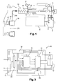
- the transmission system 3 is a simple clutch.
- the actuator 2 comprises in this example a housing 4 cooperating with the housing of an electric machine 6.
- the housing can be attached to the powertrain or the chassis of a vehicle.
- the housing 4 can receive a reducer 7 driven in rotation by the output shaft 8 of the electric machine 6, and a roto-linear motion transformation system 9.
- the gear 7 here has a fixed transmission ratio.
- the reducer 7 may comprise one or two reduction stages.
- the value of the transmission ratio of the gearbox is in the example considered determined according to the maximum force imposed by the transmission system 3 on the actuator 2, so as to reduce the electromagnetic torque to be applied to the rotor of the machine 6 when it maintains the transmission system 3 in a given state.
- the housing 4 also contains in the example considered an electronic card 10 for controlling the operation of the electric machine 6 so that the actuator 2 can have at least two distinct modes of operation.
- this command consists in modifying the torque constant of the electric machine 6 so that it can take at least two distinct values.
- a connector 11 is also carried by the housing 4, to allow the electrical connection of the electronic card 10 to a source of electrical energy which is for example the battery of the onboard network of the vehicle.
- the connector 11 may also allow the electronic card 10 to be connected to the vehicle's CAN (Controller Area Network) bus.
- the control of the electric machine 6 is thus allowed from the engine control unit (ECU) of the vehicle, the latter including implementing a monitoring software of the transmission system 3.
- ECU Engine control unit
- the housing can also receive a position sensor 12 of a movable element of the actuator 2, for example a rotor position sensor of the electric machine 6.
- This sensor 12 may or may not be carried by the electronic card 10.
- the the processing part of this sensor is for example carried by the card 10 while the measuring part of this sensor 12 is disposed at the rotor of the electric machine 6.
- the roto-linear motion transformation system 9 is for example a ball screw, a nut screw or a planetary bearing screw.
- the system 9 can thus be as described in the application filed by the Applicant on October 2, 2013 in France under the number 13 59544 whose contents are incorporated in this application by reference ..
- the system 9 allows, from rotary movement transmitted by the gear 7, to move in translation a piston 13 of a transmitter cylinder 14 for changing the state of the clutch 3.
- the receiving cylinder 18 of the example comprises an annular piston 20 coaxial with the axis of rotation X of the clutch 3.
- This annular piston 20 is in this example connected to a ball bearing 21 which moves in translation along the axis X the diaphragm of the clutch 3, for example via a fork.
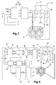
- the figure 3 functionally represents the electronic card 10. As shown in FIG. figure 3 , the electronic card 10 integrates control means of the electric machine 6 and, in the example considered, it cooperates with the sensor 12 which is external to the card 10.
- the card 10 is connected to the connector 11 which, as already mentioned, allows the transmission to the card of both power signals and control signals.
- the card 10 comprises in the example considered a module 30 for managing the power supplies of the card 10.
- This module 30 is electrically powered via the connector 11 by a source of electrical energy of the vehicle, for example the battery of the onboard network .
- the module 30 is, as shown, configured to generate power signals for electrically powering the various components of the card 10, as well as the position sensor 12 of the rotor of the electric machine 6.
- the card 10 may further comprise, as shown on the figure 3 , a static converter 31, a control system 32 of the static converter 31, a management module 33 of the communication on the CAN bus, and a current sensor 35 in the electrical machine 6.
- the module 30 can generate power signals of different value for these different components 31 to 35.
- the static converter 31 comprises in the example in question three arms 40 connected in parallel, each arm 40 being mounted between a positive DC input 47 and a negative DC input 48 of the static converter 31.
- Each arm 40 comprises two switching cells 41 in series. separated from each other by a midpoint 42, each midpoint 42 allowing the electrical connection of the converter 31 to the electrical circuit of the armature of the electrical machine 6 via a branch 44.
- Each switching cell can form a bidirectional current switch, being for example formed by a field effect transistor.
- the static converter 31 is configured to electrically supply the armature of the electric machine from the electrical power supplied by the power supply management module 30 of the card 10.
- the control system 32 of the static converter 31 comprises for example one or more microcontrollers. This or these microcontrollers are configured to communicate with other elements of the electronic card 10. They are for example configured to receive and process data from the position sensor 12 of the rotor of the electric machine 6. These data are for example transmitted in analogue form or in the form of duty cycle values. The processing of these data by the control system 32 may make it possible to carry out a closed-loop control of the actuator 2, for example in current and / or in position and / or in force.
- the control system 32 can furthermore receive and process data from the current sensor 35 in the electrical machine 6, as well as other possible sensors carried by the card 10, in particular sensors making measurements of the temperature, the voltage, and the voltage. food.
- the control system 32 can still receive and process data from external sensors to the card and whose measurements are routed to the control system 32 via the connector 11 and the management module 33.
- the control system 32 can also receive and process, via the connector 11 and the management module 33, other information relating to the control of the actuator 2, for example from the ECU, which are then decoded by this control system 32.
- the measurements thus conveyed via the connector 11 may comprise input speed measurements of a vehicle gearbox.
- the measurements conveyed via the connector 11 can comprise secondary regime oil temperature measurements or position measurements of a shift lever. speeds.
- the control system 32 can also send data via the management module 33 and the connector 11 to the outside of the electronic card 10.
- control system 32 of the static converter 31 may have analog inputs, logic inputs, analog outputs as well as outputs managing logic signals or duty cycle values for controlling the cells. switch 41 of the static converter 31.
- the management module 33 comprises electronic elements configured to manage the communication on a multiplexed network bus and to transmit information conveyed by the link to the control system 32.
- the electric machine is a DC motor comprising two poles to the stator, each of these poles being formed by a permanent magnet.
- the electrical circuit of the armature which is here the rotor, is connected via a collector 50 and brushes 51 and 52 to the midpoint 42 of each arm 40.
- each blade 51 or 52 allows the connection via a branch 44 at a midpoint 42 of an arm 40.
- the static converter 31 is a DC / DC voltage converter.
- the torque constant K is then not ⁇ not e ⁇ ⁇ 2 ⁇ .
- the invention proposes, according to the first example of implementation of the invention, to add a third brush 53 and a third arm 40 to the static converter 31.
- the latter is then in the form of three half-decks in H.
- the addition of a Third brush 53 makes it possible to vary the number of turns of the electrical circuit of the rotor traversed by the electric current I between two midpoints 42 of the static converter 31.
- the first 51 and the second brushes 52 are here arranged in the same way as the two brushes described with reference to the Figures 4a and 4b that is to say that when the current I flows between the first 51 and the second blade 52 in the electric circuit of the rotor, this current flows through all the turns of this electric circuit.
- the third blade 53 is arranged such that when the current I flows between the third blade 53 and one of the first blade 51 and the second blade 52 in the electric circuit of the rotor, this current travels only a part of the turns of the electrical circuit of the rotor.
- the current supplying the electric winding of the rotor is conveyed by the third brush 53, so that the constant can be modified.
- torque K of the electric machine 6 by changing the number of turns traveled in the electrical circuit of the rotor by this current.
- the torque constant K is then higher when the static converter 31 is controlled so that the current flows in the electrical circuit of the rotor between the first 51 and the second blade 52 when the flow of current in the electrical circuit of the rotor involves the third broom 53.
- the third brush 53 is arranged so that, when it cooperates with the collector 50 of the DC machine 6, the current I flowing between the third 53 and the first brush 51 in the
- the electrical circuit of the rotor travels a number of turns equal to that it travels when it flows between the third 53 and the second blade 52 in the electrical circuit of the rotor.
- the number of turns traversed by the current when the third brush 53 conveys said current is here equal to half the total number of turns in the electrical circuit of the rotor which is traversed by the current I between the first 51 and the second 52 brush.
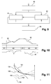
- the curves 111 and 121 reflect the existence in this case of a second value of torque constant lower than the high value of the torque constant of the case of the figure 4 .
- the curves 111 and 121 correspond to a transient operating mode of the actuator 2.
- the third blade 53 is arranged in such a way that the current I flowing between the third 53 and the first blade 51 in the electric circuit of the rotor travels a first number n 1 of turns different from a second one. number n 2 of turns it travels as it travels between the third 53 and the second 52 broom in said electrical circuit.
- the first number n 1 of turns is for example greater than the number n 2 of turns.
- the first number n 1 is for example equal to 2/3 of the total number of turns of the electrical winding of the rotor as the current flows between the first 51 and the second blade 52, while the second number n 2 is equal to 1 / 3 of said total number of turns.
- the values n 1 and n 2 respectively correspond to two low values of torque constant K, one being smaller than the other.
- curves 130, 131 and 132 representing the speed of the machine as a function of the torque T
- curves 140, 141 and 142 representing the current flowing through the electrical circuit of the rotor as a function of the torque T.
- Curves 130 and 140 which correspond to the control of the static converter 31 so that the electric current flowing through the electrical circuit of the rotor flows between the first 51 and the second blade 52, are respectively identical to the curves 100 and 101 of the figure 4b .
- These curves correspond to a control of the electric machine so that the actuator 2 is in an operating mode in which it maintains the transmission system 3 in state or in which it moves slowly.
- the curves 131 and 141 reflect the existence in this case of a first low torque constant value, while the curves 132 and 142 reflect the existence of a second value of low torque constant. These two pairs of curves correspond to configurations in which the actuator 2 moves rapidly, transiently.
- the figure 7 represents the control system 32, the static converter 31, and the dc machine of the example of the figure 5 or the example of the figure 6 .
- the control system 32 here comprises a control circuit 60 generating for certain switching cells 41 a voltage level to be applied to said cell, so as to modify the current path in the electric circuit of the rotor.
- This control circuit 60 receives, as input, duty cycle values, the identification of the switching cells 41 to be controlled, and, if necessary, the desired direction for the displacement of the actuator 2. On the basis of these inputs, the control circuit 60 determines the voltage levels to be applied to the switching cells 41 concerned.
- a quadruple of switching cells 41 that is to say the switching cells 41 of two of the arms 40, is controlled to obtain the desired operating mode of the actuator 2. For example, it would be desirable for the actuator 2 to move, thereby controlling the switching cells 41 surrounding the midpoint 42 connected to the third brush 53 and the switching cells surrounding one of the midpoint 42 connected to the first brush 51 and the point middle 42 surrounding the second broom 42.
- the current controller 61 On the basis of these inputs, the current controller 61 generates the setpoints for the control circuit 60.
- the electric machine 6 is a synchronous machine which is here with permanent magnet rotor.
- the static converter 31 is here a three-phase inverter, each arm 40 being associated with the control of a phase of the electrical circuit of the armature, which is here the stator.
- the control system 32 is configured to apply to the static converter 31 a vector control.
- a vector control For this, the Clarke and Park transforms, known to those skilled in the art, are used.
- the control system 32 interacts here with the position sensor 12, which is in the example considered a Hall effect sensor, and with the current sensor 35 which makes it possible to determine the value of the current in two of the phases of the electrical circuit of the stator.
- the three-phase system is here balanced, we can deduce the value of the current in the last phase of the electric circuit of the stator, so that we know the value of the current in each phase of the stator.
- control system 32 is configured to receive and process the data from these sensors 12 and 35.
- the control system 32 comprises an observer 70 with unknown input, receiving the values transmitted by the Hall effect sensor.
- the output of this observer 70 is a precise measurement of the electric angle of the rotor.
- the Clarke transformer is applied via a block 71 to the current in each phase of the electrical machine 6, and the outputs of this block 72 are received at the input of a block 73 which, using the value of the angle Electrical rotor provided by the observer 70, applies to these outputs the Park transform.
- the components in the Park reference frame of the current I flowing in the electrical winding of the stator are then received at the input of a current controller 75 which also receives as input a setpoint value for the internal angle ⁇ of the machine and a value I sp of current setpoint in the electric circuit of the stator, for example conveyed via the CAN link.
- the current controller 75 determines the components U d and Uq in the Park reference frame of the control voltage of the electric machine 6.
- the control voltage thus determined by this current controller aims to vary the internal angle ⁇ of the machine. Since the torque constant K is in this example equal to 3 2 ⁇ P ⁇ ⁇ ⁇ sin ⁇ , by varying the value of this internal angle, that is by defluxing the synchronous machine 6, the value of the torque constant of the machine 6 is varied, and therefore the value of this constant can be chosen. better suited to the desired operating mode of the actuator 2.
- the inverter 31 is controlled so that the internal angle ⁇ has a value of 90 ° when it is desired to maintain or slowly move the actuator, and the inverter 31 is controlled in such a way that to reduce the value of this internal angle when it is desired to obtain a rapid displacement of the actuator 2.
- Two blocks 81 and 82 successively apply to this control voltage the inverse transforms of Park and Clarke to obtain the control voltages of each phase of the electric machine 6.
- a control circuit 83 generates on the basis of these control voltages. the duty cycle values to be applied to the switching cells of the inverter 31 so as to apply these control voltages to each phase of the electric machine.
- the control system 32 of the exemplary embodiments of the invention described above can be configured to apply an auxiliary command when a failure occurs.
- This failure may be internal to the actuator 2, or affect the transmission system 3, or more generally affect an element of the propulsion system of the vehicle or more generally affect a vehicle element.
- this auxiliary control consists for example in acting on the switching cells of the static converter 31 so that the switching cell 41 of each arm 40 connecting the midpoint 42 and the positive continuous input 47 of the converter 31 is non-conducting, and that the switching cell 41 of said arm 40 connecting the midpoint 42 and the negative DC input 48 is passing. The electric machine is then disconnected from the source of electrical energy.
- the auxiliary command consists, for example, in disabling all of the switching cells 41 of the static converter 31.
- the method may comprise a step 90 of initialization of the actuator 2. This step may make it possible to determine the initial electrical angle of the rotor of the electric machine 6.
- this step may consist of applying an arbitrary voltage to the stator of the machine 6 to orient the rotor in a preferred direction and to set the observer 70 to zero.
- the actuator may be deactivated, the power supply then being interrupted.
- the figure 10 represents on the one hand on a curve 94 the set value for the position of the actuator 92 as determined for example by the engine control unit of the vehicle, and on a curve 95 the actual position of this actuator 2.
- the fact that the torque constant K has a high value during the steps 91 allows a reduced power consumption, while the fact that this torque constant K has at least a low value during the steps 92 allows rapid movement of the actuator 2 to respond to the instructions satisfactorily.
- the curves 150 and 152, respectively 151 and 153, correspond to the case where the torque constant K has a high value, respectively low.
- the fixed reduction ratio is represented by the line 155.
- the point of intersection between the curves 155 and 154 corresponds to the minimum displacement to be achieved with the gear 7 whose reduction ratio value has been determined as previously mentioned.
- the point of intersection between the curve 152 and the straight line 155 defines the current supplying the electric circuit of the armature when the torque constant K has the high value, while the intersection between the curve 151 and the straight line 155 makes it possible to define the number of revolutions of the electric machine 6 when the torque constant K has the low value, this number of revolutions being performed for a duration corresponding to the desired travel time on the output stroke of the actuator 2.
- the doublet formed by the curves 150 and 152 does not allow the actuator 2 to follow the imposed instruction but allows to consume only a reduced current.
- the control system 32 to obtain this value for the torque constant is thus particularly suitable for an operating mode of the actuator 2 corresponding to a maintenance of the transmission system 3 in a given state or a slow movement of the actuator 2.
- the doublet formed by the curves 151 and 153 allows the actuator 2 to follow the imposed instruction but requires a significant current consumption by the electric machine 6.
- the control system 32 to obtain this value for the torque constant is thus particularly adapted to a transient operating mode of the actuator 2 corresponding to a rapid displacement of the actuator 2.
- the actuator 2 thus has two distinct modes of operation despite the fact that the gear 7 has a fixed value ratio.
- the actuator and the transmission system according to the invention may form an assembly intended to be interposed between a vehicle propulsion heat engine and the vehicle gearbox.
- this assembly is intended to be interposed between a vehicle propulsion engine and a gearbox associated with a rotating electrical machine.
- two sets each comprising the actuator according to the invention and the transmission system may be used, one of the sets being for example disposed on the heat engine side and the other set being disposed on the gearbox side.
- the two sets can be associated with an electric propulsion motor, for example a rotating electrical machine.
- the transmission system on the thermal engine side then makes it possible to couple or uncouple in rotation the crankshaft of the heat engine to the rotor of the rotating electrical machine.
- the transmission system on the gearbox side then makes it possible to couple or uncouple the rotor of the rotating electrical machine to an input shaft of the gearbox.
Landscapes
- Engineering & Computer Science (AREA)
- Power Engineering (AREA)
- Mechanical Engineering (AREA)
- Transportation (AREA)
- Life Sciences & Earth Sciences (AREA)
- Sustainable Development (AREA)
- Sustainable Energy (AREA)
- General Engineering & Computer Science (AREA)
- Physics & Mathematics (AREA)
- Electromagnetism (AREA)
- Electric Propulsion And Braking For Vehicles (AREA)
- Hybrid Electric Vehicles (AREA)
Claims (15)
- Stellglied (2) für ein Fahrzeugantriebssystem (3), umfassend:- eine elektrische Maschine (6), die einen Anker und einen Stator umfasst, wobei die Maschine (6) derart ist, dass die Beziehung zwischen einer repräsentativen Größe des elektromagnetischen Drehmoments (T), das auf der Maschine (6) ausgeübt wird, und einer repräsentativen Größe des Stroms (I), der in dem Stromkreis des Ankers fließt, eine Konstante (K) zustande kommen lässt, wobei (K) die Drehmomentkonstante der elektrischen Maschine (6) ist,- einen statischen Umformer (31), der eine Vielzahl von Umrichterzellen (41) umfasst, wobei der statische Umformer (31) in einer Weise angeordnet ist, den Stromkreis des Ankers mit einer Quelle elektrischer Energie elektrisch zu verbinden, und- ein Steuerungssystem (32) der Umrichterzellen (41) des statischen Umformers (31), wobei das System in einer Weise konfiguriert ist, dass die Drehmomentkonstante (K) der elektrischen Maschine (6) zumindest zwei verschiedene Werte gemäß dem auf die Zellen (41) angewendeten Steuern annehmen kann.
- Stellglied nach Anspruch 1, umfassend ein Getriebe (7), das eine eingestellte feste Untersetzung aufweist.
- Stellglied nach Anspruch 1 oder 2, wobei der statische Umformer (31) drei Schenkel (40) umfasst, die parallel angebracht sind, wobei jeder Schenkel (40) zwei Umrichterzellen (41) in Reihe umfasst, die untereinander durch einen Mittelleiter (42) getrennt sind, wobei jeder Mittelleiter (42) die elektrische Verbindung des Umformers (31) zum Stromkreis des Ankers erlaubt.
- Stellglied nach einem der vorhergehenden Ansprüche, wobei die elektrische Maschine (6) eine Gleichstrommaschine ist, die drei Bürsten (51, 52, 53) umfasst, wobei jede Bürste mit einem der Mittelleiter (42) des statischen Umformers (31) verbunden ist.
- Stellglied nach Anspruch 4, wobei die Bürsten (51, 52, 53) in einer Weise angeordnet sind, damit, wenn sie mit dem Kollektor (50) der Gleichstrommaschine (6) zusammenwirken:- wenn der Strom (I) zwischen der ersten (51) und der zweiten (52) Bürste im Stromkreis des Ankers fließt, der Strom alle Windungen des Ankerstromkreises durchfließt, und,- wenn der Strom (I) zwischen der dritten Bürste (53) und der ersten (51) oder der zweiten (52) Bürste in dem Ankerstromkreis fließt, der Strom nur einen Teil der Windungen des Ankerstromkreises durchfließt.
- Stellglied nach Anspruch 5, wobei die Bürsten (51, 52, 53) in einer Weise angeordnet sind, damit, wenn sie mit dem Kollektor (50) der Gleichstrommaschine (6) zusammenwirken, der Strom (I), der zwischen der dritten (53) und der ersten (51) Bürste in dem Ankerstromkreis fließt, eine Windungszahl gleich der durchfließt, die er durchfließt, wenn er zwischen der dritten (53) und der zweiten (52) Bürste in dem Ankerstromkreis fließt.
- Stellglied nach Anspruch 5, wobei die Bürsten (51, 52, 53) in einer Weise angeordnet sind, damit, wenn sie mit dem Kollektor (50) der Gleichstrommaschine (6) zusammenwirken, der Strom (I), der zwischen der dritten (53) und der ersten (51) Bürste in dem Ankerstromkreis fließt, eine erste Windungszahl (n1) durchfließt, die sich von einer zweiten, vom Strom (I) durchflossenen Windungszahl (n2) unterscheidet, wenn er zwischen der dritten (53) und der zweiten (52) Bürste in dem Ankerstromkreis fließt.
- Stellglied nach einem der Ansprüche 4 bis 7, wobei das Steuerungssystem (32) der Umrichterzellen (41) in einer Weise konfiguriert ist, um mindestens Folgendes zu erlauben:- die Umrichterzellen (41) in einer Weise zu steuern, dass der Strom (I), der in dem Ankerstromkreis fließt, gleichermaßen in der ersten Bürste (51), der zweiten Bürste (52), und einem Teil der Schenkel zu den Mittelleitern (42), mit denen die Bürsten (51, 52) verbunden sind, fließt, und- die Umrichterzellen (41) in einer Weise zu steuern, dass der Strom (I), der in dem Ankerstromkreis fließt, gleichermaßen in der dritten Bürste (53) und in der ersten (51) oder der zweiten Bürste (52) und einem Teil der Schenkel zu den Mittelleitern (42), mit denen die Bürsten (51, 52, 53) verbunden sind, fließt.
- Stellglied nach Anspruch 3, wobei die elektrische Maschine (6) eine Synchronmaschine ist und der statische Umformer (31) einen Dreiphasen-Wechselrichter bildet.
- Stellglied nach Anspruch 9, wobei das Steuerungssystem (32) der Umrichterzellen (41) zum Anwenden einer Vektorsteuerung auf die Umrichterzellen (41) des Dreiphasen-Wechselrichters (31) konfiguriert ist, wobei das Steuern erlaubt, dass der Pol-Innenwinkel (Ψ) der Maschine zumindest zwei verschiedene Werte annimmt.
- Anordnung, umfassend:- ein Stellglied (2) nach einem der vorhergehenden Ansprüche, und- ein Fahrzeugantriebssystem (3), wobei das System (3) ein Organ umfasst, das geeignet ist, durch das Stellglied (2) verschoben zu werden.
- Verfahren zum Steuern eines Stellglieds (2) nach einem der vorhergehenden Ansprüche, in welchem Verfahren das Steuern der Umrichterzellen (41) des statischen Umformers (31) erlaubt, dass der Wert der Drehmomentkonstante (K) der elektrischen Maschine (6) zumindest einen hohen Wert und zumindest einen niedrigen Wert annimmt.
- Verfahren nach Anspruch 12, umfassend den Schritt (91), nach dem die Umrichterzellen (41) in einer Weise gesteuert werden, dass die Drehmomentkonstante (K) den hohen Wert annimmt, wenn das Stellglied (2) das Antriebssystem (3) in einem gegebenen Zustand hält.
- Verfahren nach Anspruch 12 oder 13, umfassend den Schritt (92), nach dem die Umrichterzellen (41) in einer Weise gesteuert werden, dass die Drehmomentkonstante (K) den niedrigen Wert annimmt, um das Stellglied (2) zu verschieben.
- Verfahren nach Anspruch 14, in dem das Antriebssystem (3) eine Einzel- oder Doppelkupplung ist, deren Ruhezustand der eingekuppelte Zustand ist, und in dem die Umrichterzellen (41) in einer Weise gesteuert werden, dass die Drehmomentkonstante (K) den hohen Wert annimmt, damit das Stellglied (2) das Antriebssystem (3) in dem ausgekuppelten Zustand hält, oder in dem das Antriebssystem (3) eine Einzel- oder Doppelkupplung ist, deren Ruhezustand der ausgekuppelte Zustand ist und in dem die Umrichterzellen (41) in einer Weise gesteuert werden, dass die Drehmomentkonstante (K) den hohen Wert annimmt, damit das Stellglied (2) das Antriebssystem (3) in dem eingekuppelten Zustand hält.
Applications Claiming Priority (1)
| Application Number | Priority Date | Filing Date | Title |
|---|---|---|---|
| FR1359775A FR3011698B1 (fr) | 2013-10-09 | 2013-10-09 | Actionneur electrique pour systeme de transmission de vehicule |
Publications (2)
| Publication Number | Publication Date |
|---|---|
| EP2860869A1 EP2860869A1 (de) | 2015-04-15 |
| EP2860869B1 true EP2860869B1 (de) | 2016-11-09 |
Family
ID=49817009
Family Applications (1)
| Application Number | Title | Priority Date | Filing Date |
|---|---|---|---|
| EP14187369.5A Active EP2860869B1 (de) | 2013-10-09 | 2014-10-01 | Elektrisches Stellglied für Übertragungssystem eines Fahrzeugs |
Country Status (6)
| Country | Link |
|---|---|
| US (1) | US10221901B2 (de) |
| EP (1) | EP2860869B1 (de) |
| KR (1) | KR102195098B1 (de) |
| CN (1) | CN104632926B (de) |
| FR (1) | FR3011698B1 (de) |
| IN (1) | IN2014DE02863A (de) |
Families Citing this family (13)
| Publication number | Priority date | Publication date | Assignee | Title |
|---|---|---|---|---|
| US9810020B2 (en) | 2011-03-11 | 2017-11-07 | Lutron Electronics Co., Inc. | Motorized window treatment |
| US10655386B2 (en) * | 2011-03-11 | 2020-05-19 | Lutron Technology Company Llc | Motorized window treatment |
| DE102015015697A1 (de) * | 2015-12-04 | 2017-06-08 | Audi Ag | Verfahren zur Ansteuerung einer elektrischen Maschine für den Antrieb eines Kraftfahrzeugs und Kraftfahrzeug |
| FR3044800B1 (fr) * | 2015-12-07 | 2018-08-17 | Valeo Schalter Und Sensoren Gmbh | Dispositif et procede d'assistance a la conduite |
| FR3054938A1 (fr) * | 2016-08-05 | 2018-02-09 | Valeo Embrayages | Actionneur electrique pour systeme de transmission de vehicule |
| FR3062758B1 (fr) * | 2017-02-09 | 2020-11-06 | Valeo Equip Electr Moteur | Procede de commande d'une machine electrique tournante lors d'un changement de modulation de type pleine onde vers une modulation de largeur d'impulsion |
| FR3069594B1 (fr) | 2017-07-31 | 2019-08-23 | Valeo Embrayages | Actionneur d'embrayage |
| FR3069597B1 (fr) | 2017-07-31 | 2019-08-23 | Valeo Embrayages | Actionneur d'embrayage |
| FR3069595B1 (fr) | 2017-07-31 | 2019-08-23 | Valeo Embrayages | Actionneur d'embrayage |
| DE102018121960A1 (de) * | 2018-09-10 | 2020-03-12 | Knorr-Bremse Systeme für Nutzfahrzeuge GmbH | Vorrichtung zur Entkopplung und zum Schutz vor Ausgleichsströmen in einem redundanten System für autonomes Fahren |
| FR3104656B1 (fr) | 2019-12-17 | 2021-11-26 | FTE automotive | Actionneur d’embrayage |
| FR3121804B1 (fr) * | 2021-04-12 | 2024-08-30 | Valeo Equip Electr Moteur | Dispositif de commande d’un onduleur/redresseur |
| US20240223049A1 (en) * | 2021-04-12 | 2024-07-04 | Valeo Equipements Electriques Moteur | Device for controlling an inverter/rectifier |
Family Cites Families (28)
| Publication number | Priority date | Publication date | Assignee | Title |
|---|---|---|---|---|
| FR1359544A (fr) | 1963-06-05 | 1964-04-24 | Mohn & Co G M B H | Calendrier mural à feuilles séparées supportées dans une traverse supérieure |
| US3469166A (en) * | 1966-10-31 | 1969-09-23 | Ford Motor Co | Direct current motor speed control |
| JPS5615155A (en) * | 1979-07-16 | 1981-02-13 | Ricoh Co Ltd | Driving method of magnet-field type motor |
| EP0231393B1 (de) * | 1985-07-26 | 1990-10-03 | Kabushiki Kaisha Toyoda Jidoshokki Seisakusho | Umsteuervorrichtung zum schnellen umschalten von vorwärts- oder rückwärtsgang bei mit automatischem getriebe ausgestattetem fahrzeug |
| US5362222A (en) * | 1993-08-31 | 1994-11-08 | Cincinnati Milacron Inc. | Injection molding machine having a vector controlled AC drive system |
| US5959430A (en) * | 1997-03-07 | 1999-09-28 | Kabushiki Kaisha Toshiba | Power conversion system |
| JP2002171778A (ja) * | 2000-09-25 | 2002-06-14 | Aisin Seiki Co Ltd | 電動モータの振動抑制制御装置及び電動モータの振動抑制制御における設計手法 |
| FR2896354B1 (fr) * | 2006-01-19 | 2011-07-15 | Valeo Embrayages | Dispositif de commande adaptative d'un actionneur, en particulier d'embrayage ou de boite de vitesses |
| JP4747968B2 (ja) * | 2006-06-30 | 2011-08-17 | トヨタ自動車株式会社 | モータ駆動装置 |
| JP4274210B2 (ja) * | 2006-08-08 | 2009-06-03 | いすゞ自動車株式会社 | 出力軸減速式デュアルクラッチ変速機 |
| JP5220293B2 (ja) * | 2006-09-11 | 2013-06-26 | カヤバ工業株式会社 | モータ制御装置、モータ制御方法およびアクチュエータ |
| FR2911698B1 (fr) * | 2007-01-24 | 2009-07-10 | Airbus France Sas | Dispositif de commande d'actionneur electromecanique. |
| EP2125469A2 (de) * | 2007-02-01 | 2009-12-02 | Fallbrook Technologies Inc. | System und verfahren zur getriebe- und/oder antriebsmotorsteuerung |
| KR101037250B1 (ko) * | 2007-05-30 | 2011-05-26 | 미쓰비시덴키 가부시키가이샤 | 차량용 조타 장치 |
| JP4900292B2 (ja) * | 2008-03-13 | 2012-03-21 | トヨタ自動車株式会社 | 車両用駆動装置の制御装置 |
| US8981696B2 (en) * | 2009-01-16 | 2015-03-17 | International Business Machines Corporation | Dynamic reconfiguration-switching of windings in an electric motor in an electric vehicle |
| US8288979B2 (en) * | 2009-01-16 | 2012-10-16 | International Business Machines Corporation | Motor control mechanism for electric vehicles |
| FR2951033B1 (fr) | 2009-10-06 | 2012-03-16 | Valeo Embrayages | Procede d'estimation en temps reel de la temperature du stator et du rotor d'une machine electrique tournante. |
| EP2573909B1 (de) * | 2010-05-18 | 2016-03-30 | Toyota Jidosha Kabushiki Kaisha | Fahrzeugsteuerungssystem |
| US8319458B2 (en) * | 2010-06-17 | 2012-11-27 | GM Global Technology Operations LLC | Vehicular electrical system and method for controlling an inverter during motor deceleration |
| US9139108B2 (en) * | 2010-11-19 | 2015-09-22 | Toyota Jidosha Kabushiki Kaisha | Control device and control method for electric powered vehicle |
| CN103228515B (zh) * | 2010-11-26 | 2015-05-20 | 丰田自动车株式会社 | 车辆用驱动装置的控制装置 |
| WO2012125414A2 (en) * | 2011-03-11 | 2012-09-20 | Lutron Electronics Co., Inc. | Motorized window treatment |
| CN103858332B (zh) * | 2011-08-18 | 2017-02-15 | 日立建机株式会社 | 电机控制装置 |
| JP5329685B2 (ja) * | 2011-12-22 | 2013-10-30 | 本田技研工業株式会社 | 車両用駆動装置 |
| JP5886734B2 (ja) * | 2012-01-10 | 2016-03-16 | 本田技研工業株式会社 | 電動車両 |
| DE102012210652A1 (de) * | 2012-06-22 | 2013-12-24 | Robert Bosch Gmbh | Verfahren und Vorrichtung zum Ansteuern eines Wechselrichters |
| US9065362B2 (en) * | 2013-06-21 | 2015-06-23 | Ford Global Technologies, Llc | Determination of hysteresis controller band for IPMSM-based drive system |
-
2013
- 2013-10-09 FR FR1359775A patent/FR3011698B1/fr active Active
-
2014
- 2014-10-01 EP EP14187369.5A patent/EP2860869B1/de active Active
- 2014-10-07 KR KR1020140134969A patent/KR102195098B1/ko active IP Right Grant
- 2014-10-08 IN IN2863DE2014 patent/IN2014DE02863A/en unknown
- 2014-10-08 US US14/509,677 patent/US10221901B2/en active Active
- 2014-10-09 CN CN201410729742.8A patent/CN104632926B/zh active Active
Non-Patent Citations (1)
| Title |
|---|
| None * |
Also Published As
| Publication number | Publication date |
|---|---|
| KR20150041746A (ko) | 2015-04-17 |
| FR3011698A1 (fr) | 2015-04-10 |
| CN104632926B (zh) | 2019-02-12 |
| CN104632926A (zh) | 2015-05-20 |
| IN2014DE02863A (de) | 2015-07-03 |
| KR102195098B1 (ko) | 2020-12-24 |
| EP2860869A1 (de) | 2015-04-15 |
| US20150096863A1 (en) | 2015-04-09 |
| FR3011698B1 (fr) | 2015-10-23 |
| US10221901B2 (en) | 2019-03-05 |
Similar Documents
| Publication | Publication Date | Title |
|---|---|---|
| EP2860869B1 (de) | Elektrisches Stellglied für Übertragungssystem eines Fahrzeugs | |
| FR2954254A1 (fr) | Procede et systeme de desaccouplement d'une machine electrique sur un train roulant de vehicule, notamment d'un vehicule automobile hybride | |
| FR2818315A1 (fr) | Procede et dispositif de commande pour determiner l'angle vilebrequin d'un moteur a combustion interne, et train d'entrainement | |
| EP3044481B1 (de) | System zur steuerung eines automatisierten getriebes | |
| EP3651345A1 (de) | Reduzierungsverfahren des rastmoments, das von gleichzeitig verwendeten bürstenlosen elektrischen motoren erzeugt wird | |
| EP3253983B1 (de) | Elektrischer stellantrieb für ein fahrzeuggetriebesystem | |
| FR2998529A1 (fr) | Procede et dispositif correspondant d'accouplement entre un arbre d'un moteur electrique et un arbre de roue d'un vehicule automobile a traction electrique ou hybride | |
| WO2018024989A1 (fr) | Actionneur electrique pour systeme de transmission de vehicule | |
| EP3361624B1 (de) | Steuerverfahren einer elektrisch umlaufenden maschine bei einem wechsel der modulation vom typ vollwelle zu einer pulsweitenmodulation | |
| EP3360709B1 (de) | Korrektor der drehzahlregelung einer elektrisch umlaufenden maschine | |
| FR2995569A1 (fr) | Procede de controle pour un actionneur de commande de la transmission d'une machine electrique de traction | |
| EP3350608A1 (de) | Verfahren zum begrenzen des verschleisses von elektromotorbürsten | |
| FR3027078A1 (fr) | Actionneur pour systeme de transmission | |
| FR3045171A1 (fr) | Procede de surveillance d'un systeme d'actionnement electromecanique | |
| FR3023659A1 (fr) | Procede de generation de signaux de commande pour gerer le fonctionnement d’un moteur synchrone, dispositif de controle et actionneur | |
| FR3051865A1 (fr) | Procede de calibrage d'un actionneur d'embrayage et actionneur ainsi obtenu | |
| FR2920732A1 (fr) | Procede de pilotage d'un changement de rapport de vitesses d'un vehicule hybride. | |
| FR3108807A1 (fr) | Machine électrique sans balai à FEM variable | |
| FR3138860A1 (fr) | minimisation du couple moteur d’une machine synchrone à rotor bobiné lors du pré-conditionnement thermique de la batterie | |
| FR3128598A1 (fr) | Procédé de calage automatique d'un capteur de position angulaire | |
| FR2915532A1 (fr) | Systeme d'arret/relance moteur a alterno-demarreur | |
| FR3079370A1 (fr) | Procede de compensation de duree de temps morts d'un onduleur d'une machine electrique tournante. | |
| FR3086129A1 (fr) | Moteur electrique rotatif a rapport poids-puissance optimise | |
| FR2843248A1 (fr) | Procede de commande de fonctionnement synchronise d'au moins deux moteurs electriques polyphases | |
| EP2815121A1 (de) | Vorrichtung und verfahren zum starten eines kraftfahrzeug-verbrennungsmotors mit einem spannungsmesssystem |
Legal Events
| Date | Code | Title | Description |
|---|---|---|---|
| PUAI | Public reference made under article 153(3) epc to a published international application that has entered the european phase |
Free format text: ORIGINAL CODE: 0009012 |
|
| 17P | Request for examination filed |
Effective date: 20141001 |
|
| AK | Designated contracting states |
Kind code of ref document: A1 Designated state(s): AL AT BE BG CH CY CZ DE DK EE ES FI FR GB GR HR HU IE IS IT LI LT LU LV MC MK MT NL NO PL PT RO RS SE SI SK SM TR |
|
| AX | Request for extension of the european patent |
Extension state: BA ME |
|
| GRAP | Despatch of communication of intention to grant a patent |
Free format text: ORIGINAL CODE: EPIDOSNIGR1 |
|
| RIC1 | Information provided on ipc code assigned before grant |
Ipc: B60L 15/20 20060101ALI20160603BHEP Ipc: B60L 11/14 20060101ALI20160603BHEP Ipc: B60L 15/02 20060101ALI20160603BHEP Ipc: H02P 6/08 20060101AFI20160603BHEP Ipc: F16D 28/00 20060101ALI20160603BHEP Ipc: B60L 3/00 20060101ALI20160603BHEP Ipc: H02P 7/00 20160101ALI20160603BHEP Ipc: B60L 1/00 20060101ALI20160603BHEP Ipc: H02P 7/03 20160101ALI20160603BHEP |
|
| INTG | Intention to grant announced |
Effective date: 20160705 |
|
| GRAS | Grant fee paid |
Free format text: ORIGINAL CODE: EPIDOSNIGR3 |
|
| GRAA | (expected) grant |
Free format text: ORIGINAL CODE: 0009210 |
|
| AK | Designated contracting states |
Kind code of ref document: B1 Designated state(s): AL AT BE BG CH CY CZ DE DK EE ES FI FR GB GR HR HU IE IS IT LI LT LU LV MC MK MT NL NO PL PT RO RS SE SI SK SM TR |
|
| REG | Reference to a national code |
Ref country code: GB Ref legal event code: FG4D Free format text: NOT ENGLISH |
|
| REG | Reference to a national code |
Ref country code: AT Ref legal event code: REF Ref document number: 844733 Country of ref document: AT Kind code of ref document: T Effective date: 20161115 Ref country code: CH Ref legal event code: EP |
|
| REG | Reference to a national code |
Ref country code: IE Ref legal event code: FG4D Free format text: LANGUAGE OF EP DOCUMENT: FRENCH |
|
| REG | Reference to a national code |
Ref country code: DE Ref legal event code: R096 Ref document number: 602014004729 Country of ref document: DE |
|
| PG25 | Lapsed in a contracting state [announced via postgrant information from national office to epo] |
Ref country code: LV Free format text: LAPSE BECAUSE OF FAILURE TO SUBMIT A TRANSLATION OF THE DESCRIPTION OR TO PAY THE FEE WITHIN THE PRESCRIBED TIME-LIMIT Effective date: 20161109 |
|
| REG | Reference to a national code |
Ref country code: LT Ref legal event code: MG4D |
|
| REG | Reference to a national code |
Ref country code: NL Ref legal event code: MP Effective date: 20161109 |
|
| REG | Reference to a national code |
Ref country code: AT Ref legal event code: MK05 Ref document number: 844733 Country of ref document: AT Kind code of ref document: T Effective date: 20161109 |
|
| PG25 | Lapsed in a contracting state [announced via postgrant information from national office to epo] |
Ref country code: SE Free format text: LAPSE BECAUSE OF FAILURE TO SUBMIT A TRANSLATION OF THE DESCRIPTION OR TO PAY THE FEE WITHIN THE PRESCRIBED TIME-LIMIT Effective date: 20161109 Ref country code: NO Free format text: LAPSE BECAUSE OF FAILURE TO SUBMIT A TRANSLATION OF THE DESCRIPTION OR TO PAY THE FEE WITHIN THE PRESCRIBED TIME-LIMIT Effective date: 20170209 Ref country code: GR Free format text: LAPSE BECAUSE OF FAILURE TO SUBMIT A TRANSLATION OF THE DESCRIPTION OR TO PAY THE FEE WITHIN THE PRESCRIBED TIME-LIMIT Effective date: 20170210 Ref country code: NL Free format text: LAPSE BECAUSE OF FAILURE TO SUBMIT A TRANSLATION OF THE DESCRIPTION OR TO PAY THE FEE WITHIN THE PRESCRIBED TIME-LIMIT Effective date: 20161109 Ref country code: LT Free format text: LAPSE BECAUSE OF FAILURE TO SUBMIT A TRANSLATION OF THE DESCRIPTION OR TO PAY THE FEE WITHIN THE PRESCRIBED TIME-LIMIT Effective date: 20161109 |
|
| PG25 | Lapsed in a contracting state [announced via postgrant information from national office to epo] |
Ref country code: FI Free format text: LAPSE BECAUSE OF FAILURE TO SUBMIT A TRANSLATION OF THE DESCRIPTION OR TO PAY THE FEE WITHIN THE PRESCRIBED TIME-LIMIT Effective date: 20161109 Ref country code: PL Free format text: LAPSE BECAUSE OF FAILURE TO SUBMIT A TRANSLATION OF THE DESCRIPTION OR TO PAY THE FEE WITHIN THE PRESCRIBED TIME-LIMIT Effective date: 20161109 Ref country code: HR Free format text: LAPSE BECAUSE OF FAILURE TO SUBMIT A TRANSLATION OF THE DESCRIPTION OR TO PAY THE FEE WITHIN THE PRESCRIBED TIME-LIMIT Effective date: 20161109 Ref country code: ES Free format text: LAPSE BECAUSE OF FAILURE TO SUBMIT A TRANSLATION OF THE DESCRIPTION OR TO PAY THE FEE WITHIN THE PRESCRIBED TIME-LIMIT Effective date: 20161109 Ref country code: RS Free format text: LAPSE BECAUSE OF FAILURE TO SUBMIT A TRANSLATION OF THE DESCRIPTION OR TO PAY THE FEE WITHIN THE PRESCRIBED TIME-LIMIT Effective date: 20161109 Ref country code: AT Free format text: LAPSE BECAUSE OF FAILURE TO SUBMIT A TRANSLATION OF THE DESCRIPTION OR TO PAY THE FEE WITHIN THE PRESCRIBED TIME-LIMIT Effective date: 20161109 Ref country code: PT Free format text: LAPSE BECAUSE OF FAILURE TO SUBMIT A TRANSLATION OF THE DESCRIPTION OR TO PAY THE FEE WITHIN THE PRESCRIBED TIME-LIMIT Effective date: 20170309 Ref country code: IS Free format text: LAPSE BECAUSE OF FAILURE TO SUBMIT A TRANSLATION OF THE DESCRIPTION OR TO PAY THE FEE WITHIN THE PRESCRIBED TIME-LIMIT Effective date: 20170309 |
|
| PG25 | Lapsed in a contracting state [announced via postgrant information from national office to epo] |
Ref country code: DK Free format text: LAPSE BECAUSE OF FAILURE TO SUBMIT A TRANSLATION OF THE DESCRIPTION OR TO PAY THE FEE WITHIN THE PRESCRIBED TIME-LIMIT Effective date: 20161109 Ref country code: RO Free format text: LAPSE BECAUSE OF FAILURE TO SUBMIT A TRANSLATION OF THE DESCRIPTION OR TO PAY THE FEE WITHIN THE PRESCRIBED TIME-LIMIT Effective date: 20161109 Ref country code: CZ Free format text: LAPSE BECAUSE OF FAILURE TO SUBMIT A TRANSLATION OF THE DESCRIPTION OR TO PAY THE FEE WITHIN THE PRESCRIBED TIME-LIMIT Effective date: 20161109 Ref country code: SK Free format text: LAPSE BECAUSE OF FAILURE TO SUBMIT A TRANSLATION OF THE DESCRIPTION OR TO PAY THE FEE WITHIN THE PRESCRIBED TIME-LIMIT Effective date: 20161109 Ref country code: EE Free format text: LAPSE BECAUSE OF FAILURE TO SUBMIT A TRANSLATION OF THE DESCRIPTION OR TO PAY THE FEE WITHIN THE PRESCRIBED TIME-LIMIT Effective date: 20161109 |
|
| REG | Reference to a national code |
Ref country code: DE Ref legal event code: R097 Ref document number: 602014004729 Country of ref document: DE |
|
| PG25 | Lapsed in a contracting state [announced via postgrant information from national office to epo] |
Ref country code: BG Free format text: LAPSE BECAUSE OF FAILURE TO SUBMIT A TRANSLATION OF THE DESCRIPTION OR TO PAY THE FEE WITHIN THE PRESCRIBED TIME-LIMIT Effective date: 20170209 Ref country code: SM Free format text: LAPSE BECAUSE OF FAILURE TO SUBMIT A TRANSLATION OF THE DESCRIPTION OR TO PAY THE FEE WITHIN THE PRESCRIBED TIME-LIMIT Effective date: 20161109 |
|
| PLBE | No opposition filed within time limit |
Free format text: ORIGINAL CODE: 0009261 |
|
| STAA | Information on the status of an ep patent application or granted ep patent |
Free format text: STATUS: NO OPPOSITION FILED WITHIN TIME LIMIT |
|
| 26N | No opposition filed |
Effective date: 20170810 |
|
| REG | Reference to a national code |
Ref country code: FR Ref legal event code: PLFP Year of fee payment: 4 |
|
| PG25 | Lapsed in a contracting state [announced via postgrant information from national office to epo] |
Ref country code: SI Free format text: LAPSE BECAUSE OF FAILURE TO SUBMIT A TRANSLATION OF THE DESCRIPTION OR TO PAY THE FEE WITHIN THE PRESCRIBED TIME-LIMIT Effective date: 20161109 |
|
| PG25 | Lapsed in a contracting state [announced via postgrant information from national office to epo] |
Ref country code: MC Free format text: LAPSE BECAUSE OF FAILURE TO SUBMIT A TRANSLATION OF THE DESCRIPTION OR TO PAY THE FEE WITHIN THE PRESCRIBED TIME-LIMIT Effective date: 20161109 |
|
| REG | Reference to a national code |
Ref country code: CH Ref legal event code: PL |
|
| REG | Reference to a national code |
Ref country code: IE Ref legal event code: MM4A |
|
| PG25 | Lapsed in a contracting state [announced via postgrant information from national office to epo] |
Ref country code: LU Free format text: LAPSE BECAUSE OF NON-PAYMENT OF DUE FEES Effective date: 20171001 Ref country code: LI Free format text: LAPSE BECAUSE OF NON-PAYMENT OF DUE FEES Effective date: 20171031 Ref country code: CH Free format text: LAPSE BECAUSE OF NON-PAYMENT OF DUE FEES Effective date: 20171031 |
|
| REG | Reference to a national code |
Ref country code: BE Ref legal event code: MM Effective date: 20171031 |
|
| PG25 | Lapsed in a contracting state [announced via postgrant information from national office to epo] |
Ref country code: BE Free format text: LAPSE BECAUSE OF NON-PAYMENT OF DUE FEES Effective date: 20171031 |
|
| PG25 | Lapsed in a contracting state [announced via postgrant information from national office to epo] |
Ref country code: MT Free format text: LAPSE BECAUSE OF FAILURE TO SUBMIT A TRANSLATION OF THE DESCRIPTION OR TO PAY THE FEE WITHIN THE PRESCRIBED TIME-LIMIT Effective date: 20161109 |
|
| REG | Reference to a national code |
Ref country code: FR Ref legal event code: PLFP Year of fee payment: 5 |
|
| PG25 | Lapsed in a contracting state [announced via postgrant information from national office to epo] |
Ref country code: IE Free format text: LAPSE BECAUSE OF NON-PAYMENT OF DUE FEES Effective date: 20171001 |
|
| PG25 | Lapsed in a contracting state [announced via postgrant information from national office to epo] |
Ref country code: HU Free format text: LAPSE BECAUSE OF FAILURE TO SUBMIT A TRANSLATION OF THE DESCRIPTION OR TO PAY THE FEE WITHIN THE PRESCRIBED TIME-LIMIT; INVALID AB INITIO Effective date: 20141001 |
|
| PG25 | Lapsed in a contracting state [announced via postgrant information from national office to epo] |
Ref country code: CY Free format text: LAPSE BECAUSE OF FAILURE TO SUBMIT A TRANSLATION OF THE DESCRIPTION OR TO PAY THE FEE WITHIN THE PRESCRIBED TIME-LIMIT Effective date: 20161109 |
|
| PG25 | Lapsed in a contracting state [announced via postgrant information from national office to epo] |
Ref country code: MK Free format text: LAPSE BECAUSE OF FAILURE TO SUBMIT A TRANSLATION OF THE DESCRIPTION OR TO PAY THE FEE WITHIN THE PRESCRIBED TIME-LIMIT Effective date: 20161109 |
|
| PG25 | Lapsed in a contracting state [announced via postgrant information from national office to epo] |
Ref country code: TR Free format text: LAPSE BECAUSE OF FAILURE TO SUBMIT A TRANSLATION OF THE DESCRIPTION OR TO PAY THE FEE WITHIN THE PRESCRIBED TIME-LIMIT Effective date: 20161109 |
|
| PG25 | Lapsed in a contracting state [announced via postgrant information from national office to epo] |
Ref country code: AL Free format text: LAPSE BECAUSE OF FAILURE TO SUBMIT A TRANSLATION OF THE DESCRIPTION OR TO PAY THE FEE WITHIN THE PRESCRIBED TIME-LIMIT Effective date: 20161109 |
|
| P01 | Opt-out of the competence of the unified patent court (upc) registered |
Effective date: 20230528 |
|
| PGFP | Annual fee paid to national office [announced via postgrant information from national office to epo] |
Ref country code: GB Payment date: 20231019 Year of fee payment: 10 |
|
| PGFP | Annual fee paid to national office [announced via postgrant information from national office to epo] |
Ref country code: IT Payment date: 20231009 Year of fee payment: 10 Ref country code: FR Payment date: 20231023 Year of fee payment: 10 Ref country code: DE Payment date: 20231011 Year of fee payment: 10 |