EP2860459A1 - Bedienanordnung für ein Haushaltsgerät und Haushaltsgerät - Google Patents
Bedienanordnung für ein Haushaltsgerät und Haushaltsgerät Download PDFInfo
- Publication number
- EP2860459A1 EP2860459A1 EP20140180746 EP14180746A EP2860459A1 EP 2860459 A1 EP2860459 A1 EP 2860459A1 EP 20140180746 EP20140180746 EP 20140180746 EP 14180746 A EP14180746 A EP 14180746A EP 2860459 A1 EP2860459 A1 EP 2860459A1
- Authority
- EP
- European Patent Office
- Prior art keywords
- radiation
- receiving
- transmitting
- operating
- operating arrangement
- Prior art date
- Legal status (The legal status is an assumption and is not a legal conclusion. Google has not performed a legal analysis and makes no representation as to the accuracy of the status listed.)
- Granted
Links
Images
Classifications
-
- F—MECHANICAL ENGINEERING; LIGHTING; HEATING; WEAPONS; BLASTING
- F24—HEATING; RANGES; VENTILATING
- F24C—DOMESTIC STOVES OR RANGES ; DETAILS OF DOMESTIC STOVES OR RANGES, OF GENERAL APPLICATION
- F24C7/00—Stoves or ranges heated by electric energy
- F24C7/08—Arrangement or mounting of control or safety devices
- F24C7/082—Arrangement or mounting of control or safety devices on ranges, e.g. control panels, illumination
- F24C7/085—Arrangement or mounting of control or safety devices on ranges, e.g. control panels, illumination on baking ovens
-
- F—MECHANICAL ENGINEERING; LIGHTING; HEATING; WEAPONS; BLASTING
- F24—HEATING; RANGES; VENTILATING
- F24C—DOMESTIC STOVES OR RANGES ; DETAILS OF DOMESTIC STOVES OR RANGES, OF GENERAL APPLICATION
- F24C7/00—Stoves or ranges heated by electric energy
- F24C7/08—Arrangement or mounting of control or safety devices
- F24C7/082—Arrangement or mounting of control or safety devices on ranges, e.g. control panels, illumination
-
- H—ELECTRICITY
- H03—ELECTRONIC CIRCUITRY
- H03K—PULSE TECHNIQUE
- H03K17/00—Electronic switching or gating, i.e. not by contact-making and –breaking
- H03K17/94—Electronic switching or gating, i.e. not by contact-making and –breaking characterised by the way in which the control signals are generated
- H03K17/965—Switches controlled by moving an element forming part of the switch
- H03K17/968—Switches controlled by moving an element forming part of the switch using opto-electronic devices
-
- H—ELECTRICITY
- H03—ELECTRONIC CIRCUITRY
- H03K—PULSE TECHNIQUE
- H03K2217/00—Indexing scheme related to electronic switching or gating, i.e. not by contact-making or -breaking covered by H03K17/00
- H03K2217/94—Indexing scheme related to electronic switching or gating, i.e. not by contact-making or -breaking covered by H03K17/00 characterised by the way in which the control signal is generated
- H03K2217/94057—Rotary switches
- H03K2217/94063—Rotary switches with optical detection
Definitions
- the present invention relates to an operating arrangement for a household appliance and a household appliance, such as a hob or gas stove.
- Operating arrangements often include moving parts, such as control knobs, slides or buttons, so that the user can set operating states of the household appliance.
- the setting selected by a user must be converted into mechanical or electrical signals in order to adapt an operating state of the household appliance accordingly.
- rotary control knobs for example, have been coupled to potentiometers that provide an electrical signal to other control devices in response to the set resistance.
- switches have also been used as parts of operating arrangements.
- coding discs have been provided between an LED as emitter and a photoreceptor as receiver. Depending on a position of the coding disc which lies between the photoreceptor and the LED emitter, further control signals can be generated.
- a rotatable control knob has been provided with a coding disc which is rotatable between a transmitter / receiver arrangement for light.
- an operating arrangement for a household appliance comprises a transmitting element for generating a transmitting radiation, a receiving element for detecting a receiving radiation and a radiation guiding element which is movably arranged such that a transmission of the transmitting radiation is changed by the transmitting element in the direction of the receiving element in dependence on a position of an operating element of the household appliance ,
- the transmitting element and the receiving element are arranged in particular on the same side with respect to the Strahlungsleitelements.
- a particularly low height results from the fact that the transmitting and the receiving element, for example, are arranged side by side and results in a height only from the height of the individual transmitting and receiving elements.
- a smaller installation space is required, because the construction heights of the transmitting and receiving elements do not add to the radiation guide element therebetween, which is, for example, a coding disk.
- the transmitting element and the receiving element are arranged next to one another and, for example, point in the same direction.
- the radiation guide is opposite to the transmitting and receiving element.
- the transmitting element and the receiving element are arranged relative to one another in such a way that, in no operating situation of the household appliance, direct radiation reaches from the transmitting element to the receiving element.
- a transmission from the radiation of the transmitting element to the receiving element takes place insofar exclusively by means of the radiation guiding element.
- the transmission element has, for example, a preferred direction for emitting the transmission radiation
- the reception element has a preferred direction for detecting the reception radiation.
- at an implementation as a light transmitter and light sensor have the two preferred directions, for example, to the radiation guide.
- the radiation guide element is configured, for example, in the manner of a cover element such that, depending on the position of the control element, radiation transport from the transmission element to the reception element is prevented or released. If, for example, the radiation-conducting element covers the transmitting or receiving element, no radiation can be transmitted between the transmitting and receiving element.
- the radiation guide for the transmitting and / or receiving radiation is at least partially impermeable. If, in particular, the radiation guide element is coupled to an operating element which is movable, the position can be detected as a function of the position of the operating element and thus of the radiation guide element and converted into a corresponding signal for an operating state.
- the radiation guiding element is set up such that, depending on the position of the operating element, the transmission radiation is directed by the transmitting element in the direction of the receiving element.
- a deflection can take place for example by a radiation line, such as an optical conductor, or a reflection of the transmission radiation to the receiving element out.
- a radiation line such as an optical conductor
- a reflection of the transmission radiation to the receiving element out one can speak of a deflecting element, which is either partially transparent to the transmitting and / or receiving radiation or, depending on the position of the operating element, reflects the transmitting radiation and to the receiving element.
- the radiation guide as a wavelength shifter, ie the receiving element receives in response to a position of the control element, on which, for example, the radiation guide is arranged as a wavelength shifter, in dependence the position of different wavelengths.
- position or a rotation angle of the operating element can be closed.
- the transmitting element and the receiving element are arranged side by side on a common carrier plate.
- the carrier plate may be, for example, a circuit board or printed circuit board.
- the radiation guide is arranged to be movable relative to the carrier plate, the transmitting element and the receiving element.
- the radiation guide is in particular coupled to a control element or is part of the same.
- the transmitting element is arranged to radiate the transmission radiation away from the carrier plate substantially perpendicularly.
- the receiving element may in particular be set up to detect the receiving radiation substantially perpendicular to the carrier plate.
- the transmitting element may emit the radiation away from the carrier plate, and the receiving element substantially detects or detects radiation that radiates perpendicular to the carrier plate.
- the operating arrangement can furthermore comprise an evaluation device, which is coupled to the receiving element and is set up to generate a control signal for the household appliance as a function of the detected receiving radiation.
- the control signal can be further processed, for example, to set an operating mode of the household appliance.
- a control signal is also understood to be a signal which merely indicates the position or position of the respective operating element.
- the operating element is assigned a plurality of pairs of transmitting and receiving elements. It is for example conceivable that a single radiation guide is arranged on a control element, which moves in the operation of the control element via pairs of transmitting and receiving elements. In this respect, individual receive signals from the receiving elements to a control device are guided, so that it can be detected over which of the several pairs of transmitting and receiving elements, the radiation guide is present.
- the transmitting and / or receiving radiation is optical radiation, and in particular infrared radiation.
- optical radiation and in particular infrared radiation.
- a household appliance for example a gas hob or a gas stove, which has an operating arrangement as described above.
- an operating mode of the household appliance is set in dependence on the control signal.
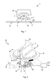
- the Fig. 1 shows a schematic representation of an embodiment of an operating arrangement for a household appliance.
- the operating arrangement 1 comprises a transmitting element 2 for transmitting radiation L and a receiving element 3 for receiving radiation L '.
- the transmitting element 2 is, for example, an LED or a light source which emits radiation in a substantially directional manner. It may be, for example, an infrared LED.
- the receiving element 3 is, for example, an infrared sensor that can detect infrared radiation. One can also speak of a transmitter / receiver arrangement or emitter sensor arrangement.
- the transmitting element 2 and the receiving element 3 are arranged adjacent to one another on a carrier plate 5.
- Fig. 1 is a preferred direction D1 for the transmission of transmission radiation L starting from the transmitting element 2 and a preferred direction D2 to be detected or detected for receiving light L 'for the receiving element 3 indicated.
- the carrier plate 5 is, for example, a circuit board, which may comprise a further wiring or additional elements.
- the operating arrangement 1 moreover comprises a radiation guiding element 4.
- the radiation guide 4 allows a deflection of the in the orientation of the Fig. 1 upwardly emitted light L in practically opposite direction as the receiving light L '.
- the diversion is in the Fig. 1 indicated by the dashed arrow.
- the transmitted light L or the transmission radiation can only reach the receiving element 3 when the radiation guide 4 is positioned accordingly.
- the deflection can be done for example by a material embodiment of the deflection or radiation guide 4.
- the deflection can be accomplished by reflection or light conduction within the deflection element 4. Also conceivable is a reflection on the underside of the deflecting element 4 from the transmitting element 2 to the receiving element 3.
- the radiation guiding element 4 in a comb-like manner, for example, such that in the method via the transmitting or receiving element 2, 3 the respective area which is set up for emitting or receiving light is covered.
- the deflection element 4 depending on a position of the radiation guide 4 relative to the transmitting and receiving elements 2, 3 can be seen where the deflection element 4 is located.
- Fig. 1 For example, conventional infrared or light emitting diodes as transmitting elements 2 have a relatively low height h compared to their lateral extent b. In this respect, transmitting elements are usually flatter than wide. Similarly, infrared sensors or light / photosensitive sensors as receiving elements 3 are shallower than their height h.
- the Strahlungsleitelement which can be configured as covering or deflecting element 4, for example, attached to a control knob, the rotatable or otherwise is mobile.
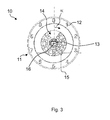
- FIG. 2 and 3 Representations of another embodiment of an operating arrangement for a household appliance are shown.
- the Fig. 2 shows a perspective view and the Fig. 3 a plan view of the further embodiment.
- the further embodiment for an operating arrangement 10 comprises an operating element 6, for example a control knob, which comprises a handling element 7 as a handle and a disc-shaped base plate 8.
- Position markers 9 are provided on one side of the handling element 7, so that an operator moves the control knob in the manner of a pointer along a scale 12, which in the Fig. 3 is indicated, can adjust.
- the respective household appliance such as a gas cooker or a gas hob
- Fig. 3 In the Fig. 3 can be seen in the representation of the control arrangement with the control knob removed, the shaft or axis 13, which defines the axis of rotation 16.
- the angle ⁇ indicates the angular position of the rotary knob 6.
- a radiation guide 4 At the bottom of the disc 8 is a radiation guide 4, as for example with respect to the Fig. 1 was explained.
- Below the movable rotary knob 6 and thus of the movable Strahlungsleitiatas 4 a plurality of pairs 15 of transmitting and receiving elements 2, 3 are provided.
- the pairs 15 are arranged around the circumference below the disc 8 at different angular positions, for example according to the scale 12 circular.
- the respective pairs 15 of transmitting / receiving and receiving elements 2, 3 are provided on a printed circuit board 5.
- the respective transmitting / receiving elements 2, 3 provide received signals to an evaluation device 17, which supplies one or more control signals CT for the household appliance. Depending on which transmit / receive pair 15 the radiation guide element 4 is present, a corresponding receive signal is supplied to the evaluation device 17.
- the radiation guide 4, as shown in the Fig. 2 is shown, the two cover with 2, 3 designated transmit and receive elements.
- the respective receiving element 3 delivers a signal to the evaluation device 17 as a function of the detected radiation which originates from the transmitting element 2.
- the proposed operating arrangement 1, 10 has a particularly low height, so that the support plate can be arranged as a board 5 with the transmitting and receiving elements 2, 3 arranged very close thereto, for example, below a hob plate. This results in a total of particularly flat cooktops or in particular flat Einbaukochmulden.
- the infrared sensors have heights h of less than 5 mm.
- the transmitting and / or receiving devices or elements are less than 2 mm. In this respect, a particularly flat configuration with a low overall height for the operating arrangement 1, 10 results.
- the deflecting, covering or radiation-guiding section 4 arranged on the underside of the control knob 6 extends through an opening 14 in the plane designed, for example, as a scale plate. It is with the help of several pairs 15 of transmitting and receiving elements 2, 3 particularly easy to detect many positions of control knobs 6 or other controls that are mobile.
- An encoding can also with the help of one or more Strahlungsleitieri 4, which are arranged on the control element 6, achieve.
- the receiving elements 3 can provide signals in response to a received radiation or received light intensity or wavelength.
- the radiation guide elements 4 can be configured as a filter, so that a changed position of the radiation guide 4 above the pair 15 of transmitting and Receiving element 2, 3 leads to an altered transmission of the transmitted light to the receiver. This change is then an indicator of the position of the control element 6.
- control signals CT are supplied by the evaluation device 17 to further, for example electronic controls of the household appliance.
- the operating mode set by the operator is set, for example, a heating power of a gas burner, which may be indicated by the scale 12.
- the radiation guide may be part of the control. It is conceivable that the radiation guide is integrated into the control.
Landscapes
- Engineering & Computer Science (AREA)
- Chemical & Material Sciences (AREA)
- Combustion & Propulsion (AREA)
- Mechanical Engineering (AREA)
- General Engineering & Computer Science (AREA)
- Selective Calling Equipment (AREA)
- Electric Stoves And Ranges (AREA)
- Arrangement Of Elements, Cooling, Sealing, Or The Like Of Lighting Devices (AREA)
Abstract
Description
- Die vorliegende Erfindung betrifft eine Bedienanordnung für ein Haushaltsgerät und ein Haushaltsgerät, wie beispielsweise ein Kochfeld oder Gasherd.
- Bedienanordnungen umfassen häufig bewegliche Teile, wie beispielsweise Bedienknebel, Schieber oder Taster, damit der Benutzer Betriebszustände des Haushaltsgeräts einstellen kann. Bei einer Bedienanordnung muss dann die von einem Nutzer gewählte Einstellung in mechanische oder elektrische Signale umgewandelt werden, um einen Betriebszustand des Haushaltsgeräts entsprechend anzupassen. In der Vergangenheit sind beispielsweise drehbare Bedienknöpfe an Potentiometer gekoppelt worden, die in Abhängigkeit von dem eingestellten Widerstand ein elektrisches Signal an weitere Steuereinrichtungen lieferte. Darüber hinaus sind auch Schalter als Teile von Bedienanordnungen verwendet worden.
- Es ist dabei wünschenswert, den häufig knappen Bauraum in Haushaltsgeräten günstig zu nutzen. Es wurde daher vorgeschlagen, optische Kopplungen zu verwenden. Dabei sind beispielsweise zwischen einer LED als Emitter und einem Photorezeptor als Empfänger Codierscheiben vorgesehen worden. In Abhängigkeit von einer Stellung der Codierscheibe, die zwischen dem Photorezeptor und dem LED-Emitter liegt, können weitere Steuersignale erzeugt werden. In Zusammenhang mit einem Herd ist beispielsweise in der
WO 2013/041518 A1 ein drehbarer Bedienknebel mit einer Codierscheibe ausgestattet worden, die zwischen einer Sende-/Empfängeranordnung für Licht drehbar ist. - Nachteilig hat sich die erforderliche Bauhöhe, welches sich aus den Dimensionen von Codierscheibe, Lichterzeuger oder Lichtquelle und Photorezeptor ergibt. Ferner erfordert eine auf einer Achse des Drehknebels aufgesetzte Codierscheibe meist eine Öffnung in einer Kochfeldplatte oder einem Verblendelement.
- Vor diesem Hintergrund ist es eine Aufgabe der vorliegenden Erfindung, eine verbesserte Bedienanordnung für ein Haushaltsgerät bereitzustellen.
- Demgemäß wird eine Bedienanordnung für ein Haushaltsgerät vorgeschlagen. Die Bedienanordnung umfasst ein Sendeelement zum Erzeugen einer Sendestrahlung, ein Empfangselement zum Erfassen einer Empfangsstrahlung und ein Strahlungsleitelement, welches derart beweglich angeordnet ist, dass in Abhängigkeit von einer Stellung eines Bedienelements des Haushaltsgeräts eine Übertragung der Sendestrahlung von dem Sendeelement in Richtung zu dem Empfangselement verändert wird. Das Sendeelement und das Empfangselement sind dabei insbesondere auf derselben Seite bezüglich des Strahlungsleitelements angeordnet.
- Bei der Bedienanordnung ergibt sich eine besonders niedrige Bauhöhe dadurch, dass das Sende- und das Empfangselement beispielsweise nebeneinander angeordnet sind und sich eine Bauhöhe lediglich aus der Höhe der einzelnen Sende- und Empfangselemente ergibt. Im Vergleich zu den bekannten optischen Codierern als Bedienanordnungen wird ein geringerer Bauraum benötigt, denn die Bauhöhen der Sende- und Empfangselemente addieren sich nicht mit dem dazwischen liegenden Strahlungsleitelement, das beispielsweise eine Codierscheibe ist.
- Durch die Verwendung von Sende- und/oder Empfangsstrahlung, die beispielsweise ein entsprechend transparentes Verblendelement oder eine Kochfeldplatte durchdringen kann, ist eine Kopplung des Strahlungsleitelementes mit dem Sende- und Empfangselement ohne Durchbrechen des Verblendelements oder der Kochfeldplatte möglich.
- In Ausführungsformen sind das Sendeelement und das Empfangselement nebeneinander angeordnet und weisen beispielsweise in dieselbe Richtung. Das Strahlungsleitelement liegt dem Sende- und Empfangselement gegenüber.
- In Ausführungsformen sind das Sendeelement und das Empfangselement derart zueinander angeordnet, dass in keiner Betriebssituation des Haushaltsgerätes eine direkte Strahlung von dem Sendeelement zu dem Empfangselement gelangt. Eine Übertragung von der Strahlung des Sendeelements zum Empfangselement erfolgt insofern ausschließlich mit Hilfe des Strahlungsleitelements. Das Sendeelement hat z.B. eine Vorzugsrichtung für eine Abstrahlung der Sendestrahlung, und das Empfangselement hat eine Vorzugsrichtung für ein Erfassen der Empfangsstrahlung. Bei einer Implementierung als Lichtsender und Lichtsensor weisen die beiden Vorzugsrichtungen beispielsweise zu dem Strahlungsleitelement.
- In Ausführungsformen ist das Strahlungsleitelement beispielsweise in der Art eines Abdeckelements derart eingerichtet, dass in Abhängigkeit von der Stellung des Bedienelements ein Strahlungstransport von dem Sendeelement zu dem Empfangselement unterbunden oder freigegeben wird. Deckt beispielsweise das Strahlungsleitelement das Sende- oder Empfangselement ab, kann keine Strahlung zwischen Sende- und Empfangselement übertragen werden. Beispielsweise ist das Strahlungsleitelement für die Sende- und/oder Empfangsstrahlung zumindest teilweise undurchlässig. Ist insbesondere das Strahlungsleitelement an ein Bedienelement gekoppelt, welches beweglich ist, kann in Abhängigkeit von der Stellung des Bedienelementes und damit des Strahlungsleitelementes die Position erkannt werden und in ein entsprechendes Signal für einen Betriebszustand umgewandelt werden.
- Insofern ergibt sich die Möglichkeit einer Codierung aus der relativen Position von Sendeelement, Empfangselement und Strahlungsleitelement.
- In Ausführungsformen der Bedienanordnung ist das Strahlungsleitelement derart eingerichtet, dass in Abhängigkeit von der Stellung des Bedienelementes die Sendestrahlung von dem Sendeelement in Richtung zu dem Empfangselement gelenkt wird.
- Eine Umlenkung kann beispielsweise durch eine Strahlungsleitung, wie beispielsweise einen optischen Leiter, oder eine Reflexion der Sendestrahlung zum Empfangselement hin erfolgen. Insofern kann man von einem Umlenkelement sprechen, welches entweder für die Sende- und/oder Empfangsstrahlung teilweise transparent ist oder in Abhängigkeit von der Stellung des Bedienelements die Sendestrahlung und zu dem Empfangselement reflektiert.
- Darüber hinaus ist es auch möglich, das Strahlungsleitelement als einen Wellenlängenverschieber einzusetzen, d.h. das Empfangselement empfängt in Abhängigkeit von einer Stellung des Bedienelementes, an dem beispielsweise das Strahlungsleitelement als Wellenlängenverschieber angeordnet ist, in Abhängigkeit von der Stellung unterschiedliche Wellenlängen. Insofern kann in Abhängigkeit von dem empfangenen Licht bzw. der Lichtfrequenz oder der Wellenlänge auf eine Position, Stellung oder einen Drehwinkel des Bedienelements geschlossen werden.
- In Ausführungsformen der Bedienanordnung sind das Sendeelement und das Empfangselement nebeneinander auf einer gemeinsamen Trägerplatte angeordnet. Die Trägerplatte kann beispielsweise eine Platine oder Leiterplatte sein.
- Vorzugsweise ist das Strahlungsleitelement gegenüber von der Trägerplatte, dem Sendeelement und dem Empfangselement beweglich angeordnet. Das Strahlungsleitelement ist insbesondere an ein Bedienelement gekoppelt oder ist Teil desselben.
- In Ausführungsformen ist das Sendeelement eingerichtet, im Wesentlichen senkrecht die Sendestrahlung von der Trägerplatte weg abzustrahlen. Das Empfangselement kann insbesondere eingerichtet sein, die Empfangsstrahlung im Wesentlichen senkrecht zu der Trägerplatte zu erfassen. In Ausführungsformen kann das Sendeelement die Strahlung von der Trägerplatte weg emittieren, und das Empfangselement erfasst oder detektiert im Wesentlichen Strahlung, die senkrecht auf die Trägerplatte einstrahlt.
- Die Bedienanordnung kann darüber hinaus eine Auswerteeinrichtung umfassen, welche an das Empfangselement gekoppelt ist und eingerichtet ist, in Abhängigkeit von der erfassten Empfangsstrahlung ein Steuersignal für das Haushaltsgerät zu erzeugen. Das Steuersignal kann beispielsweise zur Einstellung eines Betriebsmodus des Haushaltsgerätes weiter verarbeitet werden. Unter einem Steuersignal wird auch ein Signal verstanden, das lediglich die Position oder Stellung des jeweiligen Bedienelementes anzeigt.
- In Ausführungsformen der Bedienanordnung sind dem Bedienelement mehrere Paare von Sende- und Empfangselementen zugeordnet. Es ist beispielswiese denkbar, dass ein einziges Strahlungsleitelement an einem Bedienelement angeordnet ist, welches bei der Betätigung des Bedienelementes über Paare von Sende- und Empfangselementen verfährt. Insofern können einzelne Empfangssignale von den Empfangselementen zu einer Steuereinrichtung geführt werden, so dass erkannt werden kann, über welchem der mehreren Paare von Sende- und Empfangselementen das Strahlungsleitelement vorliegt.
- Vorzugsweise ist die Sende- und/oder Empfangsstrahlung optische Strahlung, und insbesondere Infrarotstrahlung. Dann lassen sich leicht ein Infrarotsender und ein Infrarotsensor, die kompakt herstellbar sind, nebeneinander anordnen.
- Darüber hinaus wird ein Haushaltsgerät vorgeschlagen, beispielsweise ein Gaskochfeld oder ein Gasherd, welches eine Bedienanordnung wie vorbeschrieben aufweist. Vorzugsweise wird in Abhängigkeit von dem Steuersignal ein Betriebsmodus des Haushaltsgerätes eingestellt.
- Weitere mögliche Implementierungen der Erfindung umfassen auch nicht explizit genannte Kombinationen von zuvor oder im Folgenden bezüglich der Ausführungsbeispiele beschriebenen Merkmalen. Dabei wird der Fachmann auch Einzelaspekte als Verbesserungen oder Ergänzungen zu der jeweiligen Grundform der Bedienanordnung oder dem Haushaltsgerät hinzufügen.
- Weitere vorteilhafte Ausgestaltungen und Aspekte der Erfindung sind Gegenstand der Unteransprüche sowie der im Folgenden beschriebenen Ausführungsbeispiele der Erfindung. Im Weiteren wird die Erfindung anhand von bevorzugten Ausführungsformen unter Bezugnahme auf die beigelegten Figuren näher erläutert.
-
Fig. 1 zeigt eine schematische Darstellung einer Ausführungsform einer Bedienanordnung für ein Haushaltsgerät; -
Fig. 2 zeigt eine perspektivische Darstellung einer weiteren Ausführungsform einer Bedienanordnung für ein Haushaltsgerät; und -
Fig. 3 zeigt eine Draufsicht der Ausführungsform einer Bedienanordnung gemäßFig. 2 . - In den Figuren sind gleiche oder funktionsgleiche Elemente mit denselben Bezugszeichen versehen, sofern nichts anderes angegeben ist.
- Die
Fig. 1 zeigt eine schematische Darstellung einer Ausführungsform für eine Bedienanordnung für ein Haushaltsgerät. Die Bedienanordnung 1 umfasst dabei ein Sendeelement 2 für Sendestrahlung L und ein Empfangselement 3 für Empfangsstrahlung L'. Das Sendeelement 2 ist beispielsweise eine LED oder eine Lichtquelle, die im Wesentlichen gerichtet Strahlung abstrahlt. Es kann sich beispielsweise um eine Infrarot-LED handeln. Das Empfangselement 3 ist beispielsweise ein Infrarotsensor, der Infrarotstrahlung erkennen kann. Man kann auch von einer Sender-/Empfängeranordnung oder Emitter-Sensoranordnung sprechen. Das Sendeelement 2 und das Empfangselement 3 sind benachbart zueinander auf einer Trägerplatte 5 angeordnet. - In der
Fig. 1 ist eine Vorzugsrichtung D1 für das Aussenden von Sendestrahlung L ausgehend vom Sendeelement 2 und eine Vorzugsrichtung D2 für zu detektierendes oder erfassendes Empfangslicht L' für das Empfangselement 3 angedeutet. Bei der Trägerplatte 5 handelt es sich beispielsweise um eine Platine, die eine weitere Verdrahtung oder zusätzliche Elemente umfassen kann. Die Bedienanordnung 1 umfasst darüber hinaus ein Strahlungsleitelement 4. - Das Strahlungsleitelement 4 ermöglicht eine Umlenkung des in der Orientierung der
Fig. 1 nach oben ausgesendeten Lichts L in praktisch entgegengesetzter Richtung als Empfangslicht L'. Die Umlenkung ist in derFig. 1 über den gestrichelten Pfeil angedeutet. Insofern kann das Sendelicht L oder die Sendestrahlung nur zu dem Empfangselement 3 gelangen, wenn das Strahlungsleitelement 4 entsprechend positioniert ist. Die Umlenkung kann dabei beispielsweise durch eine materialmäßige Ausgestaltung des Umlenk- oder Strahlungsleitelementes 4 erfolgen. Die Umlenkung kann durch Reflektion oder Lichtleitung innerhalb des Umlenkelementes 4 vollzogen werden. Denkbar ist auch eine Reflektion an der Unterseite des Umlenkelementes 4 von dem Sendeelement 2 zum Empfangselement 3. - In einer alternativen Ausgestaltung ist es auch möglich, das Strahlungsleitelement 4 beispielsweise kammartig derart auszuführen, dass beim Verfahren über das Sende- oder Empfangselement 2, 3 die jeweilige Fläche, die zum Lichtaussenden oder -empfangen eingerichtet ist, abgedeckt wird. Insofern ist in Abhängigkeit von einer Position des Strahlungsleitelements 4 relativ zu den Sende- und Empfangselementen 2, 3 erkennbar, wo sich das Umlenkelement 4 befindet. Man erkennt anhand der
Fig. 1 , dass beispielsweise übliche Infrarot- oder lichtemittierende Dioden als Sendeelemente 2 eine relativ niedrige Bauhöhe h im Vergleich zu ihrer lateralen Ausdehnung b haben. Insofern sind Sendeelemente in der Regel flacher als breit. Ähnlich sind Infrarotsensoren oder licht-/ photosensitive Sensoren als Empfangselemente 3 flacher als ihre Bauhöhe h. Da die beiden Elemente 2, 3 nebeneinander angeordnet sind, ergibt sich so insgesamt eine besonders niedrige Bauhöhe für die Bedienanordnung 1. Das Strahlungsleitelement, welches als Abdeck- oder Umlenkelement 4 ausgestaltet sein kann, ist dabei beispielsweise an einem Bedienknebel befestigt, der drehbar oder anders beweglich ist. - In den
Fig. 2 und3 sind Darstellungen einer weiteren Ausführungsform einer Bedienanordnung für ein Haushaltsgerät dargestellt. - Die
Fig. 2 zeigt eine perspektivische Darstellung und dieFig. 3 eine Draufsicht der weiteren Ausführungsform. Dabei umfasst die weitere Ausführungsform für eine Bedienanordnung 10 ein Bedienelement 6, beispielsweise einen Bedienknebel, der ein Handhabungselement 7 als Griff und eine scheibenförmige Grundplatte 8 umfasst. Es sind Positionsmarkierungen 9 an einer Seite des Handhabungselements 7 vorgesehen, so dass ein Bediener den Bedienknebel in der Art eines Zeigers entlang einer Skala 12, die in derFig. 3 angedeutet ist, einstellen kann. Um die Bedienung des jeweiligen Haushaltsgerätes, beispielsweise eines Gasherdes oder eines Gaskochfeldes, zu ermöglichen, ist es notwendig, die Stellung und insbesondere die Winkelposition des Bedienknebels 7 bezüglich seiner Drehachse 16 zur Skala 12 zu erkennen. - In der
Fig. 3 erkennt man in der Darstellung der Bedienanordnung mit abgenommenem Bedienknebel die Welle oder Achse 13, welche die Rotationsachse 16 definiert. Der Winkel α zeigt die Winkelstellung des Drehknebels 6 an. An der Unterseite der Scheibe 8 ist ein Strahlungsleitelement 4, wie es beispielsweise bezüglich derFig. 1 erläutert wurde, vorgesehen. Unterhalb des beweglichen Drehknebels 6 und damit des beweglichen Strahlungsleitelementes 4 sind mehrere Paare 15 von Sende- und Empfangselementen 2, 3 vorgesehen. Die Paare 15 sind um den Umfang herum unterhalb der Scheibe 8 an verschiedenen Winkelpositionen beispielsweise gemäß der Skala 12 kreisförmig angeordnet. Die jeweiligen Paare 15 von Sende-/Empfangs- und Empfangselementen 2, 3 sind dabei auf einer Leiterplatte 5 vorgesehen. - Die jeweiligen Sende-/Empfangselemente 2, 3 liefern Empfangssignale an eine Auswerteeinrichtung 17, die eines oder mehrere Steuersignale CT für das Haushaltsgerät liefert. Je nachdem, oberhalb welchem Sende-/Empfangspaar 15 das Strahlungsleitelement 4 vorliegt, wird ein entsprechendes Empfangssignal an die Auswerteeinrichtung 17 geliefert. Beispielsweise kann das Strahlungsleitelement 4, wie es in der
Fig. 2 dargestellt ist, die beiden mit 2, 3 bezeichneten Sende- und Empfangselemente überdecken. Je nach Ausgestaltung des Strahlungsleitelements 4 liefert das jeweilige Empfangselement 3 ein Signal in Abhängigkeit von der erfassten Strahlung, die von dem Sendeelement 2 herrührt, an die Auswerteeinrichtung 17. - Die vorgeschlagene Bedienanordnung 1, 10 hat eine besonders niedrige Bauhöhe, so dass die Trägerplatte als Platine 5 mit den darauf angeordneten Sende- und Empfangselementen 2, 3 sehr nahe beispielsweise unterhalb einer Kochfeldplatte angeordnet werden kann. Dadurch ergeben sich insgesamt besonders flache Kochfelder oder insbesondere flache Einbaukochmulden. In Ausführungsformen haben die Infrarotsensoren Bauhöhen h von kleiner als 5 mm. Vorzugsweise sind die Sende-und/oder Empfangseinrichtungen bzw. -elemente niedriger als 2 mm. Insofern ergibt sich eine besonders flache Ausgestaltung mit niedriger Bauhöhe für die Bedienanordnung 1, 10.
- Man erkennt in der
Fig. 3 , dass der an der Unterseite des Bedienknebels 6 angeordnete Umlenk-, Abdeck- oder Strahlungsleitabschnitt 4 durch eine Öffnung 14 in der beispielsweise als Skalenplatte ausgestalteten Ebene verläuft. Es ist mit Hilfe von mehreren Paaren 15 von Sende- und Empfangselementen 2, 3 besonders einfach, viele Positionen von Bedienknebeln 6 oder auch anderen Bedienelementen, die beweglich sind, zu erfassen. - Eine Codierung, wie sie Codierscheiben vollziehen, lässt sich auch mit Hilfe einer oder mehrerer Strahlungsleitelemente 4, die an dem Bedienelement 6 angeordnet sind, erzielen. Beispielsweise können insbesondere die Empfangselemente 3 Signale in Abhängigkeit von einer Empfangsstrahlungs- oder Empfangslichtstärke oder Wellenlänge liefern. Die Strahlungsleitelemente 4 können als Filter ausgestaltet werden, so dass eine veränderte Position des Strahlungsleitelementes 4 oberhalb des Paares 15 von Sende-und Empfangselement 2, 3 zu einer veränderten Übertragung des Sendelichts zum Empfänger führt. Diese Veränderung ist dann ein Indikator für die Stellung des Bedienelementes 6.
- Schließlich werden die Steuersignale CT von der Auswerteeinrichtung 17 an weitere, beispielsweise elektronische Steuerungen des Haushaltsgerätes geliefert. In der Folge wird der vom Bediener eingestellte Betriebsmodus beispielsweise eine Heizleistung eines Gasbrenners, die durch die Skala 12 angegeben sein kann, eingestellt.
- Obwohl die Erfindung vorliegend anhand bevorzugter Ausführungsbeispiele beschrieben wurde, ist sie darauf nicht beschränkt, sondern vielfältig modifizierbar. Beispielsweise kann das Strahlungsleitelement Teil des Bedienelements sein. Denkbar ist, dass das Strahlungsleitelement in das Bedienelement integriert ist.
-
- 1
- Bedienanordnung
- 2
- Sendeelement
- 3
- Empfangselement
- 4
- Strahlungsleitelement
- 5
- Trägerplatte
- 6
- Bedienelement
- 7
- Handhabungsabschnitt
- 8
- Scheibe
- 9
- Markierung
- 10
- Bedienanordnung
- 11
- Skalenkranz
- 12
- Skala
- 13
- Welle/Achse
- 14
- Öffnung
- 15
- Sende- Empfangspaar
- 16
- Drehachse
- 17
- Auswerteeinrichtung
- b
- Breite
- CT
- Steuersignale
- D1, D2
- Vorzugsrichtung
- h
- Bauhöhe
- L
- Sendestrahlung
- L'
- Empfangsstrahlung
- α
- Drehwinkel
Claims (15)
- Bedienanordnung (1) für ein Haushaltsgerät, mit einem Sendeelement (2) zum Erzeugen einer Sendestrahlung (L), einem Empfangselement (3) zum Erfassen einer Empfangsstrahlung (L') und mit einem Strahlungsleitelement (4), welches derart beweglich angeordnet ist, dass in Abhängigkeit von einer Stellung eines Bedienelements (6) des Haushaltsgeräts eine Übertragung der Sendestrahlung (L) von dem Sendelement (2) in Richtung zu dem Empfangselements (3) verändert wird, wobei das Sendelement (2) und das Empfangselement (3) auf derselben Seite des Strahlungsleitelements (4) angeordnet sind.
- Bedienanordnung (1) nach Anspruch 1, dadurch gekennzeichnet, dass das Strahlungsleitelement (4) derart eingerichtet ist, dass in Abhängigkeit von der Stellung des Bedienelements (6) ein Strahlungstransport von dem Sendelement (2) zu dem Empfangselements (3) unterbunden oder freigegeben wird.
- Bedienanordnung (1) nach Anspruch 2, dadurch gekennzeichnet, dass das Strahlungsleitelement (4) für die Sende- und/oder Empfangsstrahlung (L, L') zumindest teilweise undurchlässig ist.
- Bedienanordnung (1) nach einem der Ansprüche 1 - 3, dadurch gekennzeichnet, dass das Strahlungsleitelement (4) derart eingerichtet ist, dass in Abhängigkeit von der Stellung des Bedienelements (6) die Sendestrahlung (L) von dem Sendelement (2) in Richtung zu dem Empfangselements (3) gelenkt wird.
- Bedienanordnung (1) nach einem der Ansprüche 1 - 4, dadurch gekennzeichnet, dass das Strahlungsleitelement (4) für die Sende- und/oder Empfangsstrahlung (L, L') zumindest teilweise transparent ist.
- Bedienanordnung (1) nach einem der Ansprüche 1 - 5, dadurch gekennzeichnet, dass das Strahlungsleitelement (4) eingerichtet ist, in Abhängigkeit von der Stellung des Bedienelements (6) die Sendestrahlung (L) in Richtung zu dem Empfangselements (3) zu reflektieren.
- Bedienanordnung (1) nach einem der Ansprüche 1 - 6, dadurch gekennzeichnet, dass das Sendeelement (2) und das Empfangselement (3) nebeneinander auf einer gemeinsamen Trägerplatte (5) angeordnet sind.
- Bedienanordnung (1) nach Anspruch 7, dadurch gekennzeichnet, dass das Strahlungsleitelement (4) gegenüber von der Trägerplatte (5), dem Sendeelement (2) und dem Empfangselement (3) beweglich angeordnet ist.
- Bedienanordnung (1) nach Anspruch 7 oder 8, dadurch gekennzeichnet, dass das Sendeelement (2) eingerichtet ist, im Wesentlichen senkrecht die Sendestrahlung (L) von der Trägerplatte (5) weg abzustrahlen.
- Bedienanordnung (1) nach einem der Ansprüche 7 - 9, dadurch gekennzeichnet, dass das Empfangselement (3) eingerichtet ist, die Empfangsstrahlung (L') im Wesentlichen senkrecht zu der Trägerplatte (5) zu erfassen.
- Bedienanordnung (1) nach einem der Ansprüche 1 - 10, ferner mit einer Auswerteeinrichtung (17), welche an das Empfangselement (3) gekoppelt ist und eingerichtet ist, in Abhängigkeit von der erfassten Empfangsstrahlung (L') ein Steuersignal für das Haushaltsgerät zu erzeugen.
- Bedienanordnung (1) nach einem der Ansprüche 1 - 11, ferner mit einem Bedienelement (6), an welches das Strahlungsleitelement (4) gekoppelt ist.
- Bedienanordnung (1) nach einem der Ansprüche 1 - 12, dadurch gekennzeichnet, dass dem Bedienelement (6) mehrere Paare (15) von Sende- und Empfangselementen (2, 3) zugeordnet sind.
- Bedienanordnung (1) nach einem der Ansprüche 1 - 13, dadurch gekennzeichnet, dass die Sende- und/oder Empfangsstrahlung (L, L') optische Strahlung, insbesondere Infrarotstrahlung ist.
- Haushaltsgerät, insbesondere Gaskochfeld, mit einer Bedienanordnung nach einem der Ansprüche 11 - 14, wobei das Haushaltsgerät eingerichtet ist, dass in Abhängigkeit von dem Steuersignal (CT) ein Betriebsmodus des Haushaltsgerätes eingestellt wird.
Applications Claiming Priority (1)
| Application Number | Priority Date | Filing Date | Title |
|---|---|---|---|
| ES201331297A ES2530544B1 (es) | 2013-09-03 | 2013-09-03 | Disposición de mando para aparato doméstico, y aparato doméstico |
Publications (2)
| Publication Number | Publication Date |
|---|---|
| EP2860459A1 true EP2860459A1 (de) | 2015-04-15 |
| EP2860459B1 EP2860459B1 (de) | 2021-03-17 |
Family
ID=51357738
Family Applications (1)
| Application Number | Title | Priority Date | Filing Date |
|---|---|---|---|
| EP14180746.1A Active EP2860459B1 (de) | 2013-09-03 | 2014-08-13 | Haushaltsgerät |
Country Status (2)
| Country | Link |
|---|---|
| EP (1) | EP2860459B1 (de) |
| ES (1) | ES2530544B1 (de) |
Cited By (1)
| Publication number | Priority date | Publication date | Assignee | Title |
|---|---|---|---|---|
| WO2018014926A1 (de) * | 2016-07-22 | 2018-01-25 | Diehl Ako Stiftung & Co. Kg | Drehbetätigungsvorrichtung |
Citations (5)
| Publication number | Priority date | Publication date | Assignee | Title |
|---|---|---|---|---|
| EP0797227A2 (de) * | 1996-03-20 | 1997-09-24 | E.G.O. ELEKTRO-GERÄTEBAU GmbH | Anordnung zur Steuerung von elektrischen ansteuerbaren Geräten |
| DE10314315A1 (de) * | 2003-03-29 | 2004-10-28 | Preh Gmbh | Bedienelement |
| DE102005049995A1 (de) * | 2005-10-12 | 2007-04-19 | E.G.O. Elektro-Gerätebau GmbH | Bedienvorrichtung für ein Elektrogerät und Bedienverfahren zur Bedienung eines Elektrogerätes |
| EP1947550A1 (de) * | 2006-12-29 | 2008-07-23 | BSH Bosch und Siemens Hausgeräte GmbH | Eingabevorrichtung für ein Haushaltsgerät |
| WO2013041518A1 (en) | 2011-09-19 | 2013-03-28 | BSH Bosch und Siemens Hausgeräte GmbH | Cooker, and combination of cooker and range hood |
Family Cites Families (8)
| Publication number | Priority date | Publication date | Assignee | Title |
|---|---|---|---|---|
| DE2649647C3 (de) * | 1976-10-29 | 1982-02-04 | Siemens AG, 1000 Berlin und 8000 München | Drehschalter |
| IT1273976B (it) * | 1995-02-27 | 1997-07-11 | Whirlpool Italia | Controllo a radiofrequenza delle sorgenti termiche elettriche di piani di cottura di vetroceramica |
| DE10212953B4 (de) * | 2002-03-19 | 2005-05-04 | E.G.O. Elektro-Gerätebau GmbH | Bedienvorrichtung für ein Elektrogerät |
| FR2861212B1 (fr) * | 2003-10-20 | 2006-03-03 | Valeo Climatisation | Tableau de commande pour planche de bord de vehicule automobile muni d'au moins un bouton rotatif de reglage a commande optique. |
| EP1907756B1 (de) * | 2005-07-25 | 2012-03-28 | Arçelik Anonim Sirketi | Kochvorrichtung |
| DE102006047471B4 (de) * | 2006-10-05 | 2009-05-28 | Preh Gmbh | Impulsgeber für ein Bedienelement in einem Kraftfahrzeug |
| CN102997286A (zh) * | 2011-09-19 | 2013-03-27 | 博西华电器(江苏)有限公司 | 灶具及其与抽油烟机的组合 |
| DE102013212815A1 (de) * | 2013-07-01 | 2015-01-08 | BSH Bosch und Siemens Hausgeräte GmbH | Bedienvorrichtung mit einem Bedienelement mit einem Haftelement an der Bedienelementunterseite sowie Haushaltsgerät mit einer derartigen Bedienvorrichtung |
-
2013
- 2013-09-03 ES ES201331297A patent/ES2530544B1/es not_active Expired - Fee Related
-
2014
- 2014-08-13 EP EP14180746.1A patent/EP2860459B1/de active Active
Patent Citations (5)
| Publication number | Priority date | Publication date | Assignee | Title |
|---|---|---|---|---|
| EP0797227A2 (de) * | 1996-03-20 | 1997-09-24 | E.G.O. ELEKTRO-GERÄTEBAU GmbH | Anordnung zur Steuerung von elektrischen ansteuerbaren Geräten |
| DE10314315A1 (de) * | 2003-03-29 | 2004-10-28 | Preh Gmbh | Bedienelement |
| DE102005049995A1 (de) * | 2005-10-12 | 2007-04-19 | E.G.O. Elektro-Gerätebau GmbH | Bedienvorrichtung für ein Elektrogerät und Bedienverfahren zur Bedienung eines Elektrogerätes |
| EP1947550A1 (de) * | 2006-12-29 | 2008-07-23 | BSH Bosch und Siemens Hausgeräte GmbH | Eingabevorrichtung für ein Haushaltsgerät |
| WO2013041518A1 (en) | 2011-09-19 | 2013-03-28 | BSH Bosch und Siemens Hausgeräte GmbH | Cooker, and combination of cooker and range hood |
Cited By (2)
| Publication number | Priority date | Publication date | Assignee | Title |
|---|---|---|---|---|
| WO2018014926A1 (de) * | 2016-07-22 | 2018-01-25 | Diehl Ako Stiftung & Co. Kg | Drehbetätigungsvorrichtung |
| EP3896400A1 (de) * | 2016-07-22 | 2021-10-20 | Diehl AKO Stiftung & Co. KG | Drehbetätigungsvorrichtung |
Also Published As
| Publication number | Publication date |
|---|---|
| ES2530544B1 (es) | 2015-12-15 |
| EP2860459B1 (de) | 2021-03-17 |
| ES2530544A1 (es) | 2015-03-03 |
Similar Documents
| Publication | Publication Date | Title |
|---|---|---|
| EP2434202B2 (de) | Operationsleuchte mit steriler Bedieneinrichtung | |
| DE112008000413B4 (de) | Kochfeld mit einem bewegbaren Heizelement | |
| EP2988573B1 (de) | Kochfeldeinrichtung und verfahren zum betreiben | |
| EP1775650A2 (de) | Bedienvorrichtung für ein Elektrogerät | |
| EP2263047B1 (de) | Kochstelle mit schaltervorrichtung | |
| DE10255676B4 (de) | Bedieneinheit für ein elektrisches Gerät | |
| EP2420734A1 (de) | Bedienvorrichtung für ein Hausgerät mit einer Energieversorgungseinrichtung sowie Hausgerät zum Zubereiten von Lebensmitteln mit einer derartigen Bedienvorrichtung | |
| EP2024686B1 (de) | Hausgerät, vorzugsweise kochfeld | |
| DE102013212815A1 (de) | Bedienvorrichtung mit einem Bedienelement mit einem Haftelement an der Bedienelementunterseite sowie Haushaltsgerät mit einer derartigen Bedienvorrichtung | |
| DE102014017833B4 (de) | Dunstabzugshaube | |
| DE602004011862T2 (de) | Betätigungsvorrichtung einer Kraftfahrzeugklimaanlage | |
| EP3488190B1 (de) | Drehbetätigungsvorrichtung | |
| DE102007021297A1 (de) | Kochfeld | |
| DE102005049995A1 (de) | Bedienvorrichtung für ein Elektrogerät und Bedienverfahren zur Bedienung eines Elektrogerätes | |
| EP2701031A2 (de) | Bedienelement und Bedieneinrichtung | |
| DE102010039559A1 (de) | Bedienvorrichtung für ein Hausgerät mit einer Energieversorgungseinrichtung sowie Hausgerät zum Zubereiten von Lebensmitteln mit einer derartigen Bedienvorrichtung | |
| EP2420735B1 (de) | Bedienvorrichtung für ein Hausgerät mit einer Energieversorgungseinrichtung sowie Hausgerät zum Zubereiten von Lebensmitteln mit einer derartigen Bedienvorrichtung | |
| EP2860459B1 (de) | Haushaltsgerät | |
| WO2020079625A1 (de) | Induktionsvorrichtung | |
| EP3115758B1 (de) | Abnehmbarer kochsensor | |
| DE102012200292A1 (de) | Bedieneinrichtung für ein Haushaltsgerät sowie Haushaltsgerät mit einer derartigen Bedieneinrichtung | |
| EP3868174A1 (de) | Induktionsvorrichtung | |
| EP2455669A2 (de) | Bedienvorrichtung für ein Hausgerät mit einer muldenförmigen Aufnahme sowie Hausgerät, insbesondere Kochfeld, mit einer derartigen Bedienvorrichtung | |
| DE102016108683A1 (de) | Kochsystem mit Kochgeschirr und Induktionskochfeld | |
| EP3951268B1 (de) | Verfahren zum betrieb eines kochfelds |
Legal Events
| Date | Code | Title | Description |
|---|---|---|---|
| PUAI | Public reference made under article 153(3) epc to a published international application that has entered the european phase |
Free format text: ORIGINAL CODE: 0009012 |
|
| 17P | Request for examination filed |
Effective date: 20140813 |
|
| AK | Designated contracting states |
Kind code of ref document: A1 Designated state(s): AL AT BE BG CH CY CZ DE DK EE ES FI FR GB GR HR HU IE IS IT LI LT LU LV MC MK MT NL NO PL PT RO RS SE SI SK SM TR |
|
| AX | Request for extension of the european patent |
Extension state: BA ME |
|
| R17P | Request for examination filed (corrected) |
Effective date: 20151015 |
|
| RBV | Designated contracting states (corrected) |
Designated state(s): AL AT BE BG CH CY CZ DE DK EE ES FI FR GB GR HR HU IE IS IT LI LT LU LV MC MK MT NL NO PL PT RO RS SE SI SK SM TR |
|
| STAA | Information on the status of an ep patent application or granted ep patent |
Free format text: STATUS: EXAMINATION IS IN PROGRESS |
|
| 17Q | First examination report despatched |
Effective date: 20161121 |
|
| GRAP | Despatch of communication of intention to grant a patent |
Free format text: ORIGINAL CODE: EPIDOSNIGR1 |
|
| STAA | Information on the status of an ep patent application or granted ep patent |
Free format text: STATUS: GRANT OF PATENT IS INTENDED |
|
| RIC1 | Information provided on ipc code assigned before grant |
Ipc: H03K 17/968 20060101ALI20200624BHEP Ipc: H03K 17/965 20060101ALI20200624BHEP Ipc: F24C 7/08 20060101AFI20200624BHEP |
|
| INTG | Intention to grant announced |
Effective date: 20200709 |
|
| GRAJ | Information related to disapproval of communication of intention to grant by the applicant or resumption of examination proceedings by the epo deleted |
Free format text: ORIGINAL CODE: EPIDOSDIGR1 |
|
| STAA | Information on the status of an ep patent application or granted ep patent |
Free format text: STATUS: EXAMINATION IS IN PROGRESS |
|
| GRAP | Despatch of communication of intention to grant a patent |
Free format text: ORIGINAL CODE: EPIDOSNIGR1 |
|
| STAA | Information on the status of an ep patent application or granted ep patent |
Free format text: STATUS: GRANT OF PATENT IS INTENDED |
|
| INTC | Intention to grant announced (deleted) | ||
| INTG | Intention to grant announced |
Effective date: 20201117 |
|
| GRAS | Grant fee paid |
Free format text: ORIGINAL CODE: EPIDOSNIGR3 |
|
| GRAA | (expected) grant |
Free format text: ORIGINAL CODE: 0009210 |
|
| STAA | Information on the status of an ep patent application or granted ep patent |
Free format text: STATUS: THE PATENT HAS BEEN GRANTED |
|
| AK | Designated contracting states |
Kind code of ref document: B1 Designated state(s): AL AT BE BG CH CY CZ DE DK EE ES FI FR GB GR HR HU IE IS IT LI LT LU LV MC MK MT NL NO PL PT RO RS SE SI SK SM TR |
|
| REG | Reference to a national code |
Ref country code: GB Ref legal event code: FG4D Free format text: NOT ENGLISH |
|
| REG | Reference to a national code |
Ref country code: CH Ref legal event code: EP |
|
| REG | Reference to a national code |
Ref country code: DE Ref legal event code: R096 Ref document number: 502014015390 Country of ref document: DE |
|
| REG | Reference to a national code |
Ref country code: IE Ref legal event code: FG4D Free format text: LANGUAGE OF EP DOCUMENT: GERMAN |
|
| REG | Reference to a national code |
Ref country code: AT Ref legal event code: REF Ref document number: 1372594 Country of ref document: AT Kind code of ref document: T Effective date: 20210415 |
|
| REG | Reference to a national code |
Ref country code: LT Ref legal event code: MG9D |
|
| PG25 | Lapsed in a contracting state [announced via postgrant information from national office to epo] |
Ref country code: HR Free format text: LAPSE BECAUSE OF FAILURE TO SUBMIT A TRANSLATION OF THE DESCRIPTION OR TO PAY THE FEE WITHIN THE PRESCRIBED TIME-LIMIT Effective date: 20210317 Ref country code: GR Free format text: LAPSE BECAUSE OF FAILURE TO SUBMIT A TRANSLATION OF THE DESCRIPTION OR TO PAY THE FEE WITHIN THE PRESCRIBED TIME-LIMIT Effective date: 20210618 Ref country code: FI Free format text: LAPSE BECAUSE OF FAILURE TO SUBMIT A TRANSLATION OF THE DESCRIPTION OR TO PAY THE FEE WITHIN THE PRESCRIBED TIME-LIMIT Effective date: 20210317 Ref country code: BG Free format text: LAPSE BECAUSE OF FAILURE TO SUBMIT A TRANSLATION OF THE DESCRIPTION OR TO PAY THE FEE WITHIN THE PRESCRIBED TIME-LIMIT Effective date: 20210617 Ref country code: NO Free format text: LAPSE BECAUSE OF FAILURE TO SUBMIT A TRANSLATION OF THE DESCRIPTION OR TO PAY THE FEE WITHIN THE PRESCRIBED TIME-LIMIT Effective date: 20210617 |
|
| REG | Reference to a national code |
Ref country code: NL Ref legal event code: MP Effective date: 20210317 |
|
| PG25 | Lapsed in a contracting state [announced via postgrant information from national office to epo] |
Ref country code: RS Free format text: LAPSE BECAUSE OF FAILURE TO SUBMIT A TRANSLATION OF THE DESCRIPTION OR TO PAY THE FEE WITHIN THE PRESCRIBED TIME-LIMIT Effective date: 20210317 Ref country code: LV Free format text: LAPSE BECAUSE OF FAILURE TO SUBMIT A TRANSLATION OF THE DESCRIPTION OR TO PAY THE FEE WITHIN THE PRESCRIBED TIME-LIMIT Effective date: 20210317 Ref country code: SE Free format text: LAPSE BECAUSE OF FAILURE TO SUBMIT A TRANSLATION OF THE DESCRIPTION OR TO PAY THE FEE WITHIN THE PRESCRIBED TIME-LIMIT Effective date: 20210317 |
|
| PG25 | Lapsed in a contracting state [announced via postgrant information from national office to epo] |
Ref country code: NL Free format text: LAPSE BECAUSE OF FAILURE TO SUBMIT A TRANSLATION OF THE DESCRIPTION OR TO PAY THE FEE WITHIN THE PRESCRIBED TIME-LIMIT Effective date: 20210317 |
|
| PG25 | Lapsed in a contracting state [announced via postgrant information from national office to epo] |
Ref country code: SM Free format text: LAPSE BECAUSE OF FAILURE TO SUBMIT A TRANSLATION OF THE DESCRIPTION OR TO PAY THE FEE WITHIN THE PRESCRIBED TIME-LIMIT Effective date: 20210317 Ref country code: LT Free format text: LAPSE BECAUSE OF FAILURE TO SUBMIT A TRANSLATION OF THE DESCRIPTION OR TO PAY THE FEE WITHIN THE PRESCRIBED TIME-LIMIT Effective date: 20210317 Ref country code: EE Free format text: LAPSE BECAUSE OF FAILURE TO SUBMIT A TRANSLATION OF THE DESCRIPTION OR TO PAY THE FEE WITHIN THE PRESCRIBED TIME-LIMIT Effective date: 20210317 Ref country code: CZ Free format text: LAPSE BECAUSE OF FAILURE TO SUBMIT A TRANSLATION OF THE DESCRIPTION OR TO PAY THE FEE WITHIN THE PRESCRIBED TIME-LIMIT Effective date: 20210317 |
|
| PG25 | Lapsed in a contracting state [announced via postgrant information from national office to epo] |
Ref country code: IS Free format text: LAPSE BECAUSE OF FAILURE TO SUBMIT A TRANSLATION OF THE DESCRIPTION OR TO PAY THE FEE WITHIN THE PRESCRIBED TIME-LIMIT Effective date: 20210717 Ref country code: PT Free format text: LAPSE BECAUSE OF FAILURE TO SUBMIT A TRANSLATION OF THE DESCRIPTION OR TO PAY THE FEE WITHIN THE PRESCRIBED TIME-LIMIT Effective date: 20210719 Ref country code: PL Free format text: LAPSE BECAUSE OF FAILURE TO SUBMIT A TRANSLATION OF THE DESCRIPTION OR TO PAY THE FEE WITHIN THE PRESCRIBED TIME-LIMIT Effective date: 20210317 Ref country code: ES Free format text: LAPSE BECAUSE OF FAILURE TO SUBMIT A TRANSLATION OF THE DESCRIPTION OR TO PAY THE FEE WITHIN THE PRESCRIBED TIME-LIMIT Effective date: 20210317 Ref country code: RO Free format text: LAPSE BECAUSE OF FAILURE TO SUBMIT A TRANSLATION OF THE DESCRIPTION OR TO PAY THE FEE WITHIN THE PRESCRIBED TIME-LIMIT Effective date: 20210317 Ref country code: SK Free format text: LAPSE BECAUSE OF FAILURE TO SUBMIT A TRANSLATION OF THE DESCRIPTION OR TO PAY THE FEE WITHIN THE PRESCRIBED TIME-LIMIT Effective date: 20210317 |
|
| REG | Reference to a national code |
Ref country code: DE Ref legal event code: R097 Ref document number: 502014015390 Country of ref document: DE |
|
| PLBE | No opposition filed within time limit |
Free format text: ORIGINAL CODE: 0009261 |
|
| STAA | Information on the status of an ep patent application or granted ep patent |
Free format text: STATUS: NO OPPOSITION FILED WITHIN TIME LIMIT |
|
| PG25 | Lapsed in a contracting state [announced via postgrant information from national office to epo] |
Ref country code: DK Free format text: LAPSE BECAUSE OF FAILURE TO SUBMIT A TRANSLATION OF THE DESCRIPTION OR TO PAY THE FEE WITHIN THE PRESCRIBED TIME-LIMIT Effective date: 20210317 Ref country code: AL Free format text: LAPSE BECAUSE OF FAILURE TO SUBMIT A TRANSLATION OF THE DESCRIPTION OR TO PAY THE FEE WITHIN THE PRESCRIBED TIME-LIMIT Effective date: 20210317 |
|
| 26N | No opposition filed |
Effective date: 20211220 |
|
| PG25 | Lapsed in a contracting state [announced via postgrant information from national office to epo] |
Ref country code: SI Free format text: LAPSE BECAUSE OF FAILURE TO SUBMIT A TRANSLATION OF THE DESCRIPTION OR TO PAY THE FEE WITHIN THE PRESCRIBED TIME-LIMIT Effective date: 20210317 |
|
| REG | Reference to a national code |
Ref country code: CH Ref legal event code: PL |
|
| PG25 | Lapsed in a contracting state [announced via postgrant information from national office to epo] |
Ref country code: MC Free format text: LAPSE BECAUSE OF FAILURE TO SUBMIT A TRANSLATION OF THE DESCRIPTION OR TO PAY THE FEE WITHIN THE PRESCRIBED TIME-LIMIT Effective date: 20210317 |
|
| REG | Reference to a national code |
Ref country code: BE Ref legal event code: MM Effective date: 20210831 |
|
| PG25 | Lapsed in a contracting state [announced via postgrant information from national office to epo] |
Ref country code: LI Free format text: LAPSE BECAUSE OF NON-PAYMENT OF DUE FEES Effective date: 20210831 Ref country code: CH Free format text: LAPSE BECAUSE OF NON-PAYMENT OF DUE FEES Effective date: 20210831 |
|
| PG25 | Lapsed in a contracting state [announced via postgrant information from national office to epo] |
Ref country code: IS Free format text: LAPSE BECAUSE OF FAILURE TO SUBMIT A TRANSLATION OF THE DESCRIPTION OR TO PAY THE FEE WITHIN THE PRESCRIBED TIME-LIMIT Effective date: 20210717 Ref country code: LU Free format text: LAPSE BECAUSE OF NON-PAYMENT OF DUE FEES Effective date: 20210813 |
|
| PG25 | Lapsed in a contracting state [announced via postgrant information from national office to epo] |
Ref country code: IE Free format text: LAPSE BECAUSE OF NON-PAYMENT OF DUE FEES Effective date: 20210813 Ref country code: FR Free format text: LAPSE BECAUSE OF NON-PAYMENT OF DUE FEES Effective date: 20210831 Ref country code: BE Free format text: LAPSE BECAUSE OF NON-PAYMENT OF DUE FEES Effective date: 20210831 |
|
| REG | Reference to a national code |
Ref country code: AT Ref legal event code: MM01 Ref document number: 1372594 Country of ref document: AT Kind code of ref document: T Effective date: 20210813 |
|
| PG25 | Lapsed in a contracting state [announced via postgrant information from national office to epo] |
Ref country code: AT Free format text: LAPSE BECAUSE OF NON-PAYMENT OF DUE FEES Effective date: 20210813 |
|
| REG | Reference to a national code |
Ref country code: DE Ref legal event code: R084 Ref document number: 502014015390 Country of ref document: DE |
|
| PG25 | Lapsed in a contracting state [announced via postgrant information from national office to epo] |
Ref country code: HU Free format text: LAPSE BECAUSE OF FAILURE TO SUBMIT A TRANSLATION OF THE DESCRIPTION OR TO PAY THE FEE WITHIN THE PRESCRIBED TIME-LIMIT; INVALID AB INITIO Effective date: 20140813 |
|
| PG25 | Lapsed in a contracting state [announced via postgrant information from national office to epo] |
Ref country code: CY Free format text: LAPSE BECAUSE OF FAILURE TO SUBMIT A TRANSLATION OF THE DESCRIPTION OR TO PAY THE FEE WITHIN THE PRESCRIBED TIME-LIMIT Effective date: 20210317 |
|
| PGFP | Annual fee paid to national office [announced via postgrant information from national office to epo] |
Ref country code: DE Payment date: 20230831 Year of fee payment: 10 |
|
| PG25 | Lapsed in a contracting state [announced via postgrant information from national office to epo] |
Ref country code: MK Free format text: LAPSE BECAUSE OF FAILURE TO SUBMIT A TRANSLATION OF THE DESCRIPTION OR TO PAY THE FEE WITHIN THE PRESCRIBED TIME-LIMIT Effective date: 20210317 |
|
| PG25 | Lapsed in a contracting state [announced via postgrant information from national office to epo] |
Ref country code: MT Free format text: LAPSE BECAUSE OF FAILURE TO SUBMIT A TRANSLATION OF THE DESCRIPTION OR TO PAY THE FEE WITHIN THE PRESCRIBED TIME-LIMIT Effective date: 20210317 |
|
| REG | Reference to a national code |
Ref country code: DE Ref legal event code: R119 Ref document number: 502014015390 Country of ref document: DE |
|
| PG25 | Lapsed in a contracting state [announced via postgrant information from national office to epo] |
Ref country code: DE Free format text: LAPSE BECAUSE OF NON-PAYMENT OF DUE FEES Effective date: 20250301 |
|
| PGFP | Annual fee paid to national office [announced via postgrant information from national office to epo] |
Ref country code: TR Payment date: 20250806 Year of fee payment: 12 Ref country code: IT Payment date: 20250829 Year of fee payment: 12 |
|
| PGFP | Annual fee paid to national office [announced via postgrant information from national office to epo] |
Ref country code: GB Payment date: 20250822 Year of fee payment: 12 |