EP2860139B1 - Apparatus and method for filling a flexible transport container with vouchers - Google Patents
Apparatus and method for filling a flexible transport container with vouchers Download PDFInfo
- Publication number
- EP2860139B1 EP2860139B1 EP13187856.3A EP13187856A EP2860139B1 EP 2860139 B1 EP2860139 B1 EP 2860139B1 EP 13187856 A EP13187856 A EP 13187856A EP 2860139 B1 EP2860139 B1 EP 2860139B1
- Authority
- EP
- European Patent Office
- Prior art keywords
- value
- note
- vane
- notes
- transport container
- Prior art date
- Legal status (The legal status is an assumption and is not a legal conclusion. Google has not performed a legal analysis and makes no representation as to the accuracy of the status listed.)
- Active
Links
- 238000000034 method Methods 0.000 title claims description 10
- 230000033001 locomotion Effects 0.000 claims description 11
- 230000005484 gravity Effects 0.000 claims description 8
- 230000000284 resting effect Effects 0.000 claims 2
- 230000015572 biosynthetic process Effects 0.000 description 3
- 239000002131 composite material Substances 0.000 description 1
- 230000001419 dependent effect Effects 0.000 description 1
- 238000011161 development Methods 0.000 description 1
- 230000018109 developmental process Effects 0.000 description 1
- 230000000694 effects Effects 0.000 description 1
- 229920001971 elastomer Polymers 0.000 description 1
- 239000000806 elastomer Substances 0.000 description 1
- 239000004744 fabric Substances 0.000 description 1
- 230000001771 impaired effect Effects 0.000 description 1
- 230000014759 maintenance of location Effects 0.000 description 1
- 230000000717 retained effect Effects 0.000 description 1
- 238000000926 separation method Methods 0.000 description 1
Images


Classifications
-
- B—PERFORMING OPERATIONS; TRANSPORTING
- B65—CONVEYING; PACKING; STORING; HANDLING THIN OR FILAMENTARY MATERIAL
- B65H—HANDLING THIN OR FILAMENTARY MATERIAL, e.g. SHEETS, WEBS, CABLES
- B65H29/00—Delivering or advancing articles from machines; Advancing articles to or into piles
- B65H29/38—Delivering or advancing articles from machines; Advancing articles to or into piles by movable piling or advancing arms, frames, plates, or like members with which the articles are maintained in face contact
- B65H29/40—Members rotated about an axis perpendicular to direction of article movement, e.g. star-wheels formed by S-shaped members
-
- B—PERFORMING OPERATIONS; TRANSPORTING
- B65—CONVEYING; PACKING; STORING; HANDLING THIN OR FILAMENTARY MATERIAL
- B65H—HANDLING THIN OR FILAMENTARY MATERIAL, e.g. SHEETS, WEBS, CABLES
- B65H29/00—Delivering or advancing articles from machines; Advancing articles to or into piles
- B65H29/38—Delivering or advancing articles from machines; Advancing articles to or into piles by movable piling or advancing arms, frames, plates, or like members with which the articles are maintained in face contact
- B65H29/46—Members reciprocated in rectilinear path
-
- B—PERFORMING OPERATIONS; TRANSPORTING
- B65—CONVEYING; PACKING; STORING; HANDLING THIN OR FILAMENTARY MATERIAL
- B65B—MACHINES, APPARATUS OR DEVICES FOR, OR METHODS OF, PACKAGING ARTICLES OR MATERIALS; UNPACKING
- B65B25/00—Packaging other articles presenting special problems
- B65B25/14—Packaging paper or like sheets, envelopes, or newspapers, in flat, folded, or rolled form
-
- B—PERFORMING OPERATIONS; TRANSPORTING
- B65—CONVEYING; PACKING; STORING; HANDLING THIN OR FILAMENTARY MATERIAL
- B65B—MACHINES, APPARATUS OR DEVICES FOR, OR METHODS OF, PACKAGING ARTICLES OR MATERIALS; UNPACKING
- B65B5/00—Packaging individual articles in containers or receptacles, e.g. bags, sacks, boxes, cartons, cans, jars
- B65B5/10—Filling containers or receptacles progressively or in stages by introducing successive articles, or layers of articles
- B65B5/106—Filling containers or receptacles progressively or in stages by introducing successive articles, or layers of articles by pushers
-
- B—PERFORMING OPERATIONS; TRANSPORTING
- B65—CONVEYING; PACKING; STORING; HANDLING THIN OR FILAMENTARY MATERIAL
- B65H—HANDLING THIN OR FILAMENTARY MATERIAL, e.g. SHEETS, WEBS, CABLES
- B65H29/00—Delivering or advancing articles from machines; Advancing articles to or into piles
- B65H29/20—Delivering or advancing articles from machines; Advancing articles to or into piles by contact with rotating friction members, e.g. rollers, brushes, or cylinders
- B65H29/22—Delivering or advancing articles from machines; Advancing articles to or into piles by contact with rotating friction members, e.g. rollers, brushes, or cylinders and introducing into a pile
-
- B—PERFORMING OPERATIONS; TRANSPORTING
- B65—CONVEYING; PACKING; STORING; HANDLING THIN OR FILAMENTARY MATERIAL
- B65H—HANDLING THIN OR FILAMENTARY MATERIAL, e.g. SHEETS, WEBS, CABLES
- B65H29/00—Delivering or advancing articles from machines; Advancing articles to or into piles
- B65H29/26—Delivering or advancing articles from machines; Advancing articles to or into piles by dropping the articles
-
- B—PERFORMING OPERATIONS; TRANSPORTING
- B65—CONVEYING; PACKING; STORING; HANDLING THIN OR FILAMENTARY MATERIAL
- B65H—HANDLING THIN OR FILAMENTARY MATERIAL, e.g. SHEETS, WEBS, CABLES
- B65H29/00—Delivering or advancing articles from machines; Advancing articles to or into piles
- B65H29/70—Article bending or stiffening arrangements
-
- B—PERFORMING OPERATIONS; TRANSPORTING
- B65—CONVEYING; PACKING; STORING; HANDLING THIN OR FILAMENTARY MATERIAL
- B65H—HANDLING THIN OR FILAMENTARY MATERIAL, e.g. SHEETS, WEBS, CABLES
- B65H31/00—Pile receivers
- B65H31/02—Pile receivers with stationary end support against which pile accumulates
-
- B—PERFORMING OPERATIONS; TRANSPORTING
- B65—CONVEYING; PACKING; STORING; HANDLING THIN OR FILAMENTARY MATERIAL
- B65H—HANDLING THIN OR FILAMENTARY MATERIAL, e.g. SHEETS, WEBS, CABLES
- B65H31/00—Pile receivers
- B65H31/04—Pile receivers with movable end support arranged to recede as pile accumulates
-
- B—PERFORMING OPERATIONS; TRANSPORTING
- B65—CONVEYING; PACKING; STORING; HANDLING THIN OR FILAMENTARY MATERIAL
- B65H—HANDLING THIN OR FILAMENTARY MATERIAL, e.g. SHEETS, WEBS, CABLES
- B65H31/00—Pile receivers
- B65H31/30—Arrangements for removing completed piles
- B65H31/309—Arrangements for removing completed piles by acting on one of the outermost articles for moving the pile of articles on edge along a surface, e.g. by pushing
-
- B—PERFORMING OPERATIONS; TRANSPORTING
- B65—CONVEYING; PACKING; STORING; HANDLING THIN OR FILAMENTARY MATERIAL
- B65H—HANDLING THIN OR FILAMENTARY MATERIAL, e.g. SHEETS, WEBS, CABLES
- B65H2301/00—Handling processes for sheets or webs
- B65H2301/40—Type of handling process
- B65H2301/42—Piling, depiling, handling piles
- B65H2301/421—Forming a pile
- B65H2301/4214—Forming a pile of articles on edge
- B65H2301/42146—Forming a pile of articles on edge by introducing articles from above
-
- B—PERFORMING OPERATIONS; TRANSPORTING
- B65—CONVEYING; PACKING; STORING; HANDLING THIN OR FILAMENTARY MATERIAL
- B65H—HANDLING THIN OR FILAMENTARY MATERIAL, e.g. SHEETS, WEBS, CABLES
- B65H2404/00—Parts for transporting or guiding the handled material
- B65H2404/10—Rollers
- B65H2404/11—Details of cross-section or profile
- B65H2404/111—Details of cross-section or profile shape
- B65H2404/1114—Paddle wheel
-
- B—PERFORMING OPERATIONS; TRANSPORTING
- B65—CONVEYING; PACKING; STORING; HANDLING THIN OR FILAMENTARY MATERIAL
- B65H—HANDLING THIN OR FILAMENTARY MATERIAL, e.g. SHEETS, WEBS, CABLES
- B65H2404/00—Parts for transporting or guiding the handled material
- B65H2404/60—Other elements in face contact with handled material
- B65H2404/66—Other elements in face contact with handled material rotating around an axis perpendicular to face of material
- B65H2404/661—Paddle wheel
-
- B—PERFORMING OPERATIONS; TRANSPORTING
- B65—CONVEYING; PACKING; STORING; HANDLING THIN OR FILAMENTARY MATERIAL
- B65H—HANDLING THIN OR FILAMENTARY MATERIAL, e.g. SHEETS, WEBS, CABLES
- B65H2405/00—Parts for holding the handled material
- B65H2405/20—Cassettes, holders, bins, decks, trays, supports or magazines for sheets stacked on edge
- B65H2405/21—Parts and details thereof
- B65H2405/212—Parts and details thereof end supports
-
- B—PERFORMING OPERATIONS; TRANSPORTING
- B65—CONVEYING; PACKING; STORING; HANDLING THIN OR FILAMENTARY MATERIAL
- B65H—HANDLING THIN OR FILAMENTARY MATERIAL, e.g. SHEETS, WEBS, CABLES
- B65H2405/00—Parts for holding the handled material
- B65H2405/30—Other features of supports for sheets
- B65H2405/31—Supports for sheets fully removable from the handling machine, e.g. cassette
- B65H2405/311—Supports for sheets fully removable from the handling machine, e.g. cassette and serving also as package
-
- B—PERFORMING OPERATIONS; TRANSPORTING
- B65—CONVEYING; PACKING; STORING; HANDLING THIN OR FILAMENTARY MATERIAL
- B65H—HANDLING THIN OR FILAMENTARY MATERIAL, e.g. SHEETS, WEBS, CABLES
- B65H2701/00—Handled material; Storage means
- B65H2701/10—Handled articles or webs
- B65H2701/19—Specific article or web
- B65H2701/1912—Banknotes, bills and cheques or the like
Definitions
- the invention relates to a device for filling a flexible transport container with sheet-shaped notes of value, with a feed unit which supplies the sheet-shaped notes one by one and successively an impeller with elastic wings, after which each wing continues a single note in a rotary motion and the banknote due to its gravity in a Collection area falls and rests edgewise on a base plate.
- a feed unit which supplies the sheet-shaped notes one by one and successively an impeller with elastic wings, after which each wing continues a single note in a rotary motion and the banknote due to its gravity in a Collection area falls and rests edgewise on a base plate.
- safebags For receiving banknotes, such as banknotes in ATMs, automatic cash systems or automatic cash safes thin-walled, flexible transport containers, so-called safebags, are used, in which the notes of value are similar to a plastic bag. Before the notes of value are transported into the transport container, they must be stacked so that the filling of the transport container takes place in batches. Forming the stacks of notes is critical because, on the one hand, the batching process must be relatively quick and, on the other hand, the delivery of notes of value to the stack must be clearly arranged to avoid confusion of the notes of value.
- WO 2013/079717 For stacking an impeller is used with elastic wings, wherein the subsidized note of value rests against a stack wall. If a value note stack is formed, the stack is conveyed to the opening of the transport container and stowed in it with the aid of a discharge unit. Between the transport container and the discharge unit, a closure unit in the form of a shutter device is arranged, which forms the stack wall in the closed state and in the opened state allows the stacked notes of value to pass to the transport container.
- notes of value in the loose composite of the stack can tilt in the transport movement to the transport container or undergo changes in position.
- the discharge unit has an elastic guide element connected to it, which guides the value note fed from the blade of the impeller downward and vertically downwards to the base plate.
- an elastic guide element connected to it, which guides the value note fed from the blade of the impeller downward and vertically downwards to the base plate.
- the elastic guide member on the discharge unit does not change the location of the bank note, but merely provides guidance in dropping the note due to its gravity. In this way, an orderly stack of notes of value arises in the collecting area, which can be moved by the discharge unit into the transport container.
- the guide element fastened to the removal unit gently presses against the last value note of the stack because of its elasticity, so that this stack changes from a loose state to a slightly denser state in which it is easier to move and retains its geometric shape. In this way, the reliability in the transport of the stack is further improved.
- the impeller comprises seen in the axial direction spaced apart impeller wheels whose wings are aligned in the axial direction with each other.
- the subdivision into sub-vane wheels allows a further reduction of the frictional force exerted on the note without impairing the function of the guide.
- the elastic guide element seen in the axial direction comprises guide fingers, which are spaced apart from each other and the spaces between the Operaerielizan are arranged opposite.
- the frictional force acting on the value note is further reduced without the Function of leadership is impaired. Due to the arrangement in the area between the sub-wing wheels, the guidance of the notes of value along the wings and along the guide fingers is improved in a combinatorial guiding effect.
- a method for filling a transport container with bills is specified.
- the notes of value are guided by a feed unit via an impeller to a collecting area and fall there due to their gravity vertically downwards and are edgewise on a bottom plate.
- the notes of value are guided along an elastic guide element, which is attached to the discharge unit.
- This discharge unit conveys a stack formed from notes in the open state of the closure unit for opening the thin-walled, flexible transport container, wherein the elastic guide element presses against the uppermost banknote of the stack.
- FIG. 1 shows a schematic side view of an apparatus 10 for feeding notes of value 12 to a thin-walled, flexible transport container 14.
- transport container 14 is, for example, a thin plastic bag in which the notes of value are taken 12 for later onward transport.
- a plastic bag for receiving banknotes 12 is often referred to as Safebag.
- the notes of value 12 are conveyed in the direction P1 via a feed unit 16 along conveyor rails 18, 20 through transport roller pairs 22, 24, 26.
- An impeller 28 having a plurality of blades 30 (two blades 30 in this example) further feed the bills of stock 12 arriving at the end of the conveyor rails 18, 20 as they rotate in the direction P3.
- a banknote 12 thus promoted is conveyed into the clearance area 32, it falls vertically downward due to its gravity to be collected in a collecting area 34.
- the note 12 is in this collection area 34 upright on a bottom plate 36.
- the first note 12 is applied to a stacking wall 38, which is formed by a shutter of the shutter unit 40.
- the stack wall 38 has a small angle to the vertical, so that the note 12 is slightly ajar.
- a discharge unit 42 which can be moved along the double arrow P2 has a front plate 44 which carries an elastic and flexible guide element 46 in its upper region.
- This guide element 46 is convexly curved from the perspective of the stack 31. If the note 12 due to its gravity falls down to the bottom plate 36, so it is guided by the guide member 46 so that the note 12 applies in the correct position to the stack wall 38 and to the last stacked banknote 12. Thus, the note 12 is guided on its falling down on the one hand by the wing 30 and on the other hand by the guide member 46.
- the stacking wall 38 moves upwards according to the principle of a shutter, with a shutter roller 41 moving upwards and a flexible sheet, for example a fabric sheet, with gentle unrolling on the first Wertschein the stack 31 rolls up.
- a shutter roller 41 moving upwards and a flexible sheet, for example a fabric sheet, with gentle unrolling on the first Wertschein the stack 31 rolls up.
- a flexible sheet for example a fabric sheet
- the discharge unit 42 moves in FIG. 1 to the right to convey the formed stack of notes 12 into this transport container 14.
- elastic guide member 46 fulfills a further function.
- the notes of value 12 in the stack 31 are loosely layered; in the movement of the discharge unit 42 to the right first presses the elastic guide element 46 against this stack 31 and compacts it.
- the stack 31 is more stable in shape and it is reliably supplied by the front plate 44 in the further movement of the discharge unit 42 to the transport container 14, without that bank notes 12 move.
- the discharge unit 42 according to the double arrow P2 to the left in FIG. 1 moves and there is a further formation of banknotes 12 to another stack.
- FIG. 2 shows in a perspective view of the impeller 28 with 5 spaced apart vane wheels whose wings 30a to 30e aligned with each other in the axial direction. They cooperate with guide fingers 46 a, 46 b, 46 c, which form the elastic guide element 46. When seen in plan view from above, these guide fingers 46a to 46c are arranged so as to face the gaps between the vanes 30a to 30e. In this way, reduced friction force is exerted on the respective bill 12 by the guide fingers 46a to 46c and the wings 30a to 30e.
- the guide fingers 46a to 46c and the wings 30a to 30e are made of elastic plastic, for example of an elastomer.
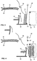
- FIGS. 3 to 5 show in a schematic representation of the stacking of the notes of value 12 and their transport in the For filling with notes of value 12, the transport container 14, for example, a kind of plastic bag, turned to the left, so that, as long as no notes of value are taken up in it 12, swept its inside out and its outside is directed inward.
- the transport container 14 is slipped over a closure frame 50, through which an opening is formed, through which the notes of value 12 are supplied to the transport container 14.
- opposing elements of the closure frame 50 are moved towards each other, whereby the opening of the transport container 14 is irreversibly closed.
- latching elements are provided, which engage in such a way for closing the transport container 14 that they are not destructively releasable again.
- notes of value 12 along guide rails 18, 20 are supplied to the impeller 28, the wings pass the notes of value 12, so that they rest edgewise on the bottom plate 36.
- the first bill of quantities 12 of the forming stack 31 abuts against the shutter of the shutter unit 40, which is in a closed position.
- the discharge unit 42 supports with its guide element 46, the formation of the stack 31.
- the spring force of the guide element 46 causes an ordered supply of the banknote 12 to the forming stack 31 (in practice, the guide element further arranged in the figure to the right towards the stack 31, which is not shown in the schematic drawing for reasons of clarity).
- the closure unit 40 is in the in FIG. 3 shown closed position so that it closes the stack 31 in the direction of the transport container 14.
- the associated blind forms the stack wall, on which the first note 12 of the stack 31 is based.
- the locking unit 40 is designed as a shutter device, wherein in the closed position, the shutter is largely fully unrolled.
- FIG. 4 shows a second operating state in which the shutter of the shutter unit 40 is rolled up and thus releases an opening in the closure frame 50.
- the discharge unit 42 is in FIG. 4 moved to the right and pushes, supported by the resilient guide member 46, the stack 31 through the opening formed into the transport unit 14, wherein the stack 31 presses against the inside turned inside out of the transport container 14 and thus everting it gradually, the inside points inwards and contacted the banknotes 12.
- FIG. 5 shows a third operating state in which the discharge unit 42 is moved back in the direction of the indicated arrow.
- the guide element 48 cushions the reverse pressure resulting from the driving of the discharge unit, so that the stack 31 reliably and in the correct position in the transport container remains.
- the shutter of the shutter unit 40 is partially unwound so that it is in a retaining position. In this position, the opening for the transport containers 14 is partially closed, to such an extent that the discharge unit 42 can retract to its original position.
- the stored in the transport container 14 notes of value 12 are retained in this retention position, whereby a safe storage of notes of value 12 in the transport container 14 is possible.
- the evacuation unit 42 continues to move back until it is in the position shown in FIG. 3 has reached, are again supplied in the notes of value 12 on the guide rails 18, 20 and stacked. For this purpose, the shutter of the shutter unit 40 is again left fully down to form a stack wall for the stack 31 to be formed.
Description
Die Erfindung betrifft eine Vorrichtung zum Befüllen eines flexiblen Transportbehälters mit blattförmigen Wertscheinen, mit einer Zuführeinheit, die die blattförmigen Wertscheine einzeln und nacheinander einem Flügelrad mit elastischen Flügeln zuführt, wonach jeder Flügel einen einzelnen Wertschein in einer Drehbewegung weiterführt und der Wertschein aufgrund seiner Schwerkraft in einen Sammelbereich fällt und dort hochkant auf einer Bodenplatte aufliegt. Eine derartige Vorrichtung ist aus der
Zur Aufnahme von Wertscheinen, beispielsweise Banknoten in Geldautomaten, automatischen Kassensystemen oder automatischen Tresorkassen werden dünnwandige, flexible Transportbehälter, sogenannte Safebags, eingesetzt, in denen die Wertscheine ähnlich wie in einem Plastikbeutel aufgenommen werden. Bevor die Wertscheine in den Transportbehälter transportiert werden, müssen diese gestapelt werden, so dass das Befüllen des Transportbehälters stapelweise erfolgt. Das Bilden der Stapel von Wertscheinen ist kritisch, denn einerseits muss der Stapelvorgang relativ schnell erfolgen und andererseits muss die Zuführung von Wertscheinen zu dem Stapel klar geordnet erfolgen, um ein Durcheinander der Wertscheine zu vermeiden.For receiving banknotes, such as banknotes in ATMs, automatic cash systems or automatic cash safes thin-walled, flexible transport containers, so-called safebags, are used, in which the notes of value are similar to a plastic bag. Before the notes of value are transported into the transport container, they must be stacked so that the filling of the transport container takes place in batches. Forming the stacks of notes is critical because, on the one hand, the batching process must be relatively quick and, on the other hand, the delivery of notes of value to the stack must be clearly arranged to avoid confusion of the notes of value.
Gemäß der eingangs erwähnten
In der Praxis hat sich gezeigt, dass bei einer schnellen Zuführung von Wertscheinen es geschehen kann, dass ein Wertschein verkantet oder nicht lagerichtig sich an den vorherigen Wertschein bei der Stapelbildung anlegt. Außerdem können Wertscheine im lockeren Verbund des Stapels bei der Transportbewegung zum Transportbehälter verkanten oder Lageänderungen erfahren.In practice, it has been shown that with a rapid delivery of notes of value, it can happen that a note is tilted or incorrectly applies itself to the previous note in the stack formation. In addition, notes of value in the loose composite of the stack can tilt in the transport movement to the transport container or undergo changes in position.
Es ist daher Aufgabe der Erfindung, eine Vorrichtung und ein Verfahren zum Befüllen eines dünnwandigen Transportbehälters mit Wertscheinen anzugeben, mit deren bzw. dessen Hilfe ein schnelles Stapeln von Wertscheinen zuverlässig möglich ist.It is therefore an object of the invention to provide a device and a method for filling a thin-walled transport container with banknotes, with their or whose help a quick stacking of notes of value is reliably possible.
Diese Aufgabe wird durch eine Vorrichtung mit den Merkmalen des Anspruchs 1 sowie durch ein Verfahren mit den Merkmalen des unabhängigen Verfahrensanspruchs gelöst. Vorteilhafte Weiterbildungen der Erfindung sind in den abhängigen Ansprüchen angegeben.This object is achieved by a device having the features of claim 1 and by a method having the features of the independent method claim. Advantageous developments of the invention are specified in the dependent claims.
Bei der Vorrichtung nach der Erfindung weist die Abführeinheit ein mit ihr verbundenes, elastisches Führungselement auf, das den vom Flügel des Flügelrads zugeführten und vertikal nach unten fallenden Wertschein nach unten zur Bodenplatte führt. Auf diese Weise erfolgt einerseits eine Führung des dem Stapel zugeführten Wertscheins durch den elastischen Flügel des Flügelrads im oberen Bereich des Wertscheins und zusätzlich eine Führung durch das elastische Führungselement im unteren Bereich des Wertscheins. Auf diese Weise ist eine Verlagerung oder ein Verkippen des zugeführten Wertscheins infolge der verbesserten Führung nicht möglich. Das Stapeln von Wertscheinen wird dadurch auch bei einer schnellen Zuführung von Wertscheinen zuverlässig und ordnungsgemäß erledigt. Die Elastizität von Flügel und Führungselement ist so gewählt, dass die auf den Wertschein wirkenden Reibungskräfte deutlich kleiner sind als die Gewichtskraft des Wertscheins. Dadurch wird verhindert, dass beim Weiterdrehen des Flügelrads die Hochkantlage des Wertscheins auf der Bodenplatte nicht verändert wird, auch dann nicht, wenn der Flügel bei seiner Weiterdrehung den Wertschein gegen den bereits vorhandenen Stapel drückt. In ähnlicher Weise verändert auch das elastische Führungselement an der Abführeinheit die Lage des Wertscheins nicht, sondern bildet lediglich eine Führung beim Herunterfallen des Wertscheins aufgrund seiner Schwerkraft. Auf diese Weise entsteht im Sammelbereich ein geordneter Stapel von Wertscheinen, der von der Abführeinheit in den Transportbehälter verschoben werden kann.In the device according to the invention, the discharge unit has an elastic guide element connected to it, which guides the value note fed from the blade of the impeller downward and vertically downwards to the base plate. In this way, on the one hand a guide of the stack supplied note of value through the elastic wing of the impeller in the upper part of the note and additionally a guide by the elastic guide element in the lower part of the note. In this way, a shift or tilting of the supplied note of value as a result of the improved guidance is not possible. The stacking of banknotes is thereby reliably and properly done even with a quick supply of banknotes. The elasticity of wing and guide element is chosen so that the friction forces acting on the value note are significantly smaller than the weight of the note. This prevents that the upright position of the note on the bottom plate is not changed during further rotation of the impeller, not even if the wing pushes the bill of exchange against the already existing stack in its further rotation. Likewise, the elastic guide member on the discharge unit does not change the location of the bank note, but merely provides guidance in dropping the note due to its gravity. In this way, an orderly stack of notes of value arises in the collecting area, which can be moved by the discharge unit into the transport container.
Wenn die Abführeinheit den Stapel an Wertscheinen im geöffneten Zustand der Verschlusseinheit zur Öffnung des Transportbehälters fördert, so drückt das an der Abführeinheit befestigte Führungselement aufgrund seiner Elastizität sanft gegen den letzten Wertschein des Stapels, so dass dieser Stapel aus einem lockeren Zustand in einen etwas dichteren Zustand gelangt, in welchem er leichter verschiebbar ist und seine geometrische Form beibehält. Auf diese Weise ist die Zuverlässigkeit beim Transport des Stapels weiter verbessert.When the discharge unit conveys the stack of banknotes in the opened state of the closure unit to the opening of the transport container, the guide element fastened to the removal unit gently presses against the last value note of the stack because of its elasticity, so that this stack changes from a loose state to a slightly denser state in which it is easier to move and retains its geometric shape. In this way, the reliability in the transport of the stack is further improved.
Gemäß einem Ausführungsbeispiel umfasst das Flügelrad in axialer Richtung gesehen voneinander beabstandete Teilflügelräder, deren Flügel in axialer Richtung gesehen miteinander fluchten. Die Aufteilung in Teilflügelräder ermöglicht eine weitere Verringerung der auf den Wertschein ausgeübten Reibungskraft, ohne dass hierbei die Funktion der Führung beeinträchtigt wird.According to one embodiment, the impeller comprises seen in the axial direction spaced apart impeller wheels whose wings are aligned in the axial direction with each other. The subdivision into sub-vane wheels allows a further reduction of the frictional force exerted on the note without impairing the function of the guide.
Vorteilhaft ist es, wenn das elastische Führungselement in axialer Richtung gesehen Führungsfinger umfasst, die voneinander beabstandet sind und den Zwischenräumen zwischen den Teilflügelrädern gegenüberliegend angeordnet sind. Durch das Aufteilen in Führungsfinger wird die auf den Wertschein wirkende Reibungskraft weiter verringert, ohne dass die Funktion der Führung beeinträchtigt wird. Aufgrund der Anordnung im Bereich zwischen den Teilflügelrädern wird die Führung der Wertscheine entlang der Flügel und entlang der Führungsfinger in einem kombinatorischen Führungseffekt verbessert.It is advantageous if the elastic guide element seen in the axial direction comprises guide fingers, which are spaced apart from each other and the spaces between the Teilflügelrädern are arranged opposite. By dividing into guide fingers, the frictional force acting on the value note is further reduced without the Function of leadership is impaired. Due to the arrangement in the area between the sub-wing wheels, the guidance of the notes of value along the wings and along the guide fingers is improved in a combinatorial guiding effect.
Vorteilhaft ist es, wenn das Führungselement bzw. die Führungsfinger vom Wertscheinstapel her gesehen konvex gebogen sind. Hierdurch werden die auf die Wertscheine wirkenden Reibungskräfte weiter verringert, ohne die Führungsfunktion einzuschränken.It is advantageous if the guide element or the guide fingers are bent convexly seen from the note stack. As a result, the frictional forces acting on the notes of value are further reduced without restricting the guiding function.
Gemäß einem weiteren Aspekt der Erfindung wird ein Verfahren zum Befüllen eines Transportbehälters mit Wertscheinen angegeben. Bei diesem Verfahren werden die Wertscheine von einer Zuführeinheit über ein Flügelrad zu einem Sammelbereich geführt und fallen dort aufgrund ihrer Schwerkraft vertikal nach unten und liegen hochkant auf einer Bodenplatte auf. Bei diesem Herunterfallen werden die Wertscheine entlang einem elastischen Führungselement geführt, welches an der Abführeinheit befestigt ist. Diese Abführeinheit fördert einen aus Wertscheinen gebildeten Stapel in geöffnetem Zustand der Verschlusseinheit zur Öffnung des dünnwandigen, flexiblen Transportbehälters, wobei das elastische Führungselement gegen den obersten Wertschein des Stapels drückt.According to a further aspect of the invention, a method for filling a transport container with bills is specified. In this method, the notes of value are guided by a feed unit via an impeller to a collecting area and fall there due to their gravity vertically downwards and are edgewise on a bottom plate. In this fall, the notes of value are guided along an elastic guide element, which is attached to the discharge unit. This discharge unit conveys a stack formed from notes in the open state of the closure unit for opening the thin-walled, flexible transport container, wherein the elastic guide element presses against the uppermost banknote of the stack.
Gemäß diesem Verfahren erfolgt ein zuverlässiges und sicheres Stapeln von Wertscheinen auch bei einer schnellen Zuführung von Wertscheinen. Außerdem wird eine kompakte Form des Wertscheinstapels erreicht, was bei der Förderung des Stapels in den Transportbehälter durch die Abführeinheit vorteilhaft ist.According to this method, a reliable and secure stacking of banknotes takes place even with a fast feed of notes of value. In addition, a compact form of the value note stack is achieved, which is advantageous in the promotion of the stack in the transport container through the discharge unit.
Weitere Merkmale und Vorteile der Erfindung ergeben sich aus der folgenden Beschreibung, die die Erfindung anhand von Ausführungsbeispielen in Zusammenhang mit den beigefügten Figuren näher erläutert. Es zeigen:
- Figur 1
- eine schematische Darstellung einer Vorrichtung zum Zuführen von Wertscheinen zu einem Transportbehälter,
Figur 2- eine perspektivische Ansicht des Flügelrades und der Abführeinheit,
- Figur 3
- eine schematische Darstellung der Vorrichtung nach
Figur 1 in einem ersten Betriebszustand, - Figur 4
- eine schematische Darstellung der Vorrichtung in einem zweiten Betriebszustand, bei dem ein Stapel von Wertscheinen in den Transportbehälter transportiert wird, und
- Figur 5
- eine schematische Darstellung der Vorrichtung in einem dritten Betriebszustand, bei dem die Abführeinheit zurückgezogen wird, um den ersten Betriebszustand zu erreichen.
- FIG. 1
- a schematic representation of an apparatus for supplying notes of value to a transport container,
- FIG. 2
- a perspective view of the impeller and the discharge unit,
- FIG. 3
- a schematic representation of the device according to
FIG. 1 in a first operating state, - FIG. 4
- a schematic representation of the device in a second operating state in which a stack of bills is transported into the transport container, and
- FIG. 5
- a schematic representation of the device in a third operating state in which the discharge unit is retracted to achieve the first operating state.
Die Wertscheine 12 werden in Richtung P1 über eine Zuführeinheit 16 entlang Förderschienen 18, 20 durch Transport-Rollenpaare 22, 24, 26 gefördert. Ein Flügelrad 28 mit mehreren Flügeln 30 (in diesem Beispiel zwei Flügel 30) fördern die am Ende der Förderschienen 18, 20 ankommenden Wertscheine 12 bei ihrer Drehbewegung in Richtung P3 weiter. Wenn ein so geförderter Wertscheine 12 in den Freiraumbereich 32 gefördert ist, so fällt er aufgrund seiner Schwerkraft vertikal nach unten, um in einem Sammelbereich 34 gesammelt zu werden. Der Wertschein 12 liegt in diesem Sammelbereich 34 hochkant auf einer Bodenplatte 36 auf. Der erste Wertschein 12 liegt an einer Stapelwand 38 an, die durch eine Jalousie der Verschlusseinheit 40 gebildet wird. Die Stapelwand 38 hat einen kleinen Winkel zur Vertikalen, so dass der Wertschein 12 leicht angelehnt ist. Bei der Weiterdrehung des Flügelrads 28 führt der Flügel 30 den zugeführten Wertschein dem sich bildenden Stapel 31 zu und drückt den jeweiligen Wertschein 12 leicht gegen den Stapel 31.The notes of
Eine entlang dem Doppelpfeil P2 bewegbare Abführeinheit 42 hat eine Frontplatte 44, welches in seinem oberen Bereich ein elastisches und biegsames Führungselement 46 trägt. Dieses Führungselement 46 ist aus Sicht des Stapels 31 konvex gewölbt. Wenn der Wertschein 12 aufgrund seiner Schwerkraft nach unten zur Bodenplatte 36 fällt, so wird er durch das Führungselement 46 geführt, so dass sich der Wertschein 12 lagerichtig an die Stapelwand 38 bzw. an den letzten gestapelten Wertschein 12 anlegt. Somit wird der Wertschein 12 bei seinem Herunterfallen einerseits durch den Flügel 30 und andererseits durch das Führungselement 46 geführt.A
Wenn der Stapel 31 von Wertscheinen 12 einen ausreichenden Umfang hat, z.B. 30 Wertscheine, so fährt die Stapelwand 38 nach dem Prinzip einer Jalousie nach oben, wobei eine Jalousierolle 41 nach oben fährt und eine flexible Bahn, beispielsweise eine Stoffbahn, mit sanftem Abrollen am ersten Wertschein des Stapels 31 aufrollt. Damit wird eine Öffnung zum Transportbehälter 14 freigegeben und die Abführeinheit 42 bewegt sich in
In den nachfolgenden Figuren werden gleiche Elemente gleich bezeichnet.In the following figures, the same elements are referred to the same.
Die
Wie im Zusammenhang mit
Die Vereinzelung der Wertscheine 12, die Zuführung über die Zuführeinheit 16, sowie der Antrieb des Flügelrads 28, der Abführeinheit 42, der Verschlusseinheit 40 und des Verschlussrahmens 50 erfolgt mit Hilfe einer Steuerung (nicht dargestellt), die auch die verschiedenen mechanischen Bewegungen synchronisiert. Ein Beispiel für eine solche Steuerung sowie weitere Details für die Verschlusseinheit 40 sind in der bereits erwähnten
- 1010
- Vorrichtung zum Zuführen von WertscheinenDevice for feeding notes of value
- 1212
- Wertscheinof notes
- 1414
- Transportbehältertransport container
- P1P1
- Richtungspfeilarrow
- 1616
- Zuführeinheitfeed
- 18, 2018, 20
- Förderschienenconveyor rails
- 22, 24, 2622, 24, 26
- Transport-RollenpaareTransport roller pairs
- 2828
- Flügelradimpeller
- 3030
- Flügelwing
- P3P3
- Richtungspfeilarrow
- 3131
- Stapelstack
- 3232
- FreiraumbereichClearance region
- 3434
- Sammelbereichcollecting area
- 3636
- Bodenplattebaseplate
- 3838
- Stapelwandstacking wall
- 4040
- Verschlusseinheitshutter unit
- P2P2
- Richtungspfeilarrow
- 4141
- Jalousierolleblind roller
- 4242
- Abführeinheitdischarge unit
- 4444
- Frontplattefront panel
- 4646
- Führungselementguide element
- 46a - 46c46a - 46c
- Führungsfingerguide fingers
- 5050
- Verschlussrahmenclosure frame
Claims (10)
- Device for filling a transport container (14) with sheet-like notes of value (12), comprising:a feeding unit (16) which feeds the sheet-like notes of value (12) individually and one after the other to a vane wheel (28) having elastic vanes (30), wherein each vane (30) forwards a note of value (12) in a rotary movement and the note of value (12) falls into a collecting area (34) due to its gravity and rests on edge on a bottom plate (36) in the collecting area,wherein, when the vane wheel (28) is rotated further, the vane (30) guides the note of value (12) resting on edge in the direction of a stacking wall (38),a closure unit (40) which forms the stacking wall (38) in a closed position and lets stacked notes of value (12) pass in the horizontal direction towards an opening of the thin-walled, flexible transport container (14) in an open position,and a removal unit (42) which conveys the stack (31) of notes of value (12) in the open state of the closure unit (40) to the opening of the transport container (14),characterized in that the removal unit (42) has an elastic guide element (46) mounted thereon which limits the movement of the note of value (12) fed by the vane (30) of the vane wheel (28) and falling vertically downwards.
- Device according to Claim 1, characterized in that, as viewed in the axial direction, the vane wheel (28) comprises spaced-apart partial vane wheels of which the vanes (30a-30e) are aligned with one another as viewed in the axial direction.
- Device according to Claim 2, characterized in that, as viewed in the axial direction, the elastic guide element (46) comprises guide fingers (46a, 46b, 46c) which, as viewed from above in plan view, are arranged opposite the spaces between the partial vane wheels.
- Device according to one of the preceding claims, characterized in that the guide element (46) or the guide fingers (46a, 46b, 46c) are convexly bent.
- Device according to one of the preceding claims, characterized in that there is a clearance (32) between the ends of the vanes (30; 30a-30e) and the boundary of the guide element (46) or the guide fingers (46a, 46b, 46c), which clearance allows the conveyed note of value (12) to fall downwardly onto the bottom plate (36) under its own gravity.
- Device according to one of the preceding claims, characterized in that the vane wheel (28) is arranged in such a way that the ends of the respective vane (30; 30a-30e) press the respective note of value (12) in its upper region against the stacking wall (38) or against the note of value (12) fed to the stack (31) when the vane wheel (28) is rotated further.
- Device according to one of the preceding claims, characterized in that the elastic guide element (46) is made of resilient plastic.
- Device according to one of the preceding claims, characterized in that the vanes (30; 30a-30e) of the vane wheel (28) are made of elastic plastic.
- Method for filling a transport container (14) with sheet-like notes of value (12),
in which a feeding unit (16) feeds the sheet-like notes of value (12) individually and one after the other to a vane wheel (28) having elastic vanes (30), wherein each vane (30) forwards a note of value (12) in a rotary movement and the note of value (12) falls into a collecting area (34) due to its gravity and rests on edge on a bottom plate (36) in the collecting area,
when the vane wheel (28) is rotated further, the vane (30) guides the note of value (12) resting on edge in the direction of a stacking wall (38),
a closure unit (40), which forms the stacking wall (38) in a closed position, lets stacked notes of value (12) pass in the horizontal direction towards an opening of the thin-walled, flexible transport container (14) in an open position,
a removal unit (42) conveys the stack (31) of notes of value (12) in the open state of the closure unit (40) to the opening of the transport container (14),
and in which the removal unit (42) has an elastic guide element (46) mounted thereon which limits the movement of the note of value (12) fed by the vane (30) of the vane wheel (28) and falling vertically downwards. - Method according to Claim 9, characterized in that the vane wheel (28) is arranged in such a way that the ends of the respective vane (30; 30a-30e) press the respective note of value (12) in its upper region against the stacking wall (38) or against the note of value (12) fed to the stack (31) when the vane wheel (28) is rotated further.
Priority Applications (3)
| Application Number | Priority Date | Filing Date | Title |
|---|---|---|---|
| EP13187856.3A EP2860139B1 (en) | 2013-10-09 | 2013-10-09 | Apparatus and method for filling a flexible transport container with vouchers |
| ES13187856.3T ES2576112T3 (en) | 2013-10-09 | 2013-10-09 | Device and procedure for filling a flexible transport container with valuable documents |
| US14/505,654 US9096404B2 (en) | 2013-10-09 | 2014-10-03 | Device and method for filling a flexible transport container with notes of value |
Applications Claiming Priority (1)
| Application Number | Priority Date | Filing Date | Title |
|---|---|---|---|
| EP13187856.3A EP2860139B1 (en) | 2013-10-09 | 2013-10-09 | Apparatus and method for filling a flexible transport container with vouchers |
Publications (2)
| Publication Number | Publication Date |
|---|---|
| EP2860139A1 EP2860139A1 (en) | 2015-04-15 |
| EP2860139B1 true EP2860139B1 (en) | 2016-03-16 |
Family
ID=49378079
Family Applications (1)
| Application Number | Title | Priority Date | Filing Date |
|---|---|---|---|
| EP13187856.3A Active EP2860139B1 (en) | 2013-10-09 | 2013-10-09 | Apparatus and method for filling a flexible transport container with vouchers |
Country Status (3)
| Country | Link |
|---|---|
| US (1) | US9096404B2 (en) |
| EP (1) | EP2860139B1 (en) |
| ES (1) | ES2576112T3 (en) |
Families Citing this family (10)
| Publication number | Priority date | Publication date | Assignee | Title |
|---|---|---|---|---|
| DE102011055992A1 (en) * | 2011-12-02 | 2013-06-06 | Wincor Nixdorf International Gmbh | Apparatus and method for filling a thin-walled transport container |
| DE102012022228A1 (en) * | 2012-11-14 | 2014-05-15 | Winkler + Dünnebier Gmbh | Method and apparatus for forming product stacks of folded or unfolded product blanks of paper, pulp or the like |
| EP2757535B1 (en) * | 2013-01-16 | 2017-08-16 | Wincor Nixdorf International GmbH | Device for filling a thin-walled transport container with vouchers |
| EP2778105B1 (en) * | 2013-03-11 | 2016-10-26 | Wincor Nixdorf International GmbH | Apparatus and method for filling a transport container with vouchers |
| US20180318994A1 (en) * | 2017-05-05 | 2018-11-08 | Apex Mfg. Co., Ltd. | Electric stapler |
| US20180318995A1 (en) * | 2017-05-05 | 2018-11-08 | Apex Mfg. Co., Ltd. | Electric stapler |
| JP6972767B2 (en) * | 2017-08-22 | 2021-11-24 | 富士フイルムビジネスイノベーション株式会社 | Image forming device |
| JP2019125239A (en) | 2018-01-18 | 2019-07-25 | グローリー株式会社 | Paper sheet storage device and paper sheet storage method |
| CN108516390B (en) * | 2018-03-30 | 2019-07-30 | 重庆华康印务有限公司 | A kind of invoice printed product collating unit |
| GB2573997A (en) * | 2018-05-17 | 2019-11-27 | Cash Dynamics Ltd | Banknote storage cassette and bag for storing banknotes |
Family Cites Families (25)
| Publication number | Priority date | Publication date | Assignee | Title |
|---|---|---|---|---|
| US1269673A (en) * | 1917-11-20 | 1918-06-18 | United Sealing Machine Company | Stacking mechanism. |
| US1778781A (en) * | 1928-12-22 | 1930-10-21 | Wood Newspaper Mach Corp | Delivery-belt-supporting means for folding machines |
| US4052053A (en) * | 1976-01-28 | 1977-10-04 | Fuji Giken Kabushiki Kaisha | Stacker drum of sheet accumulating device |
| SE7711413L (en) * | 1977-10-11 | 1979-04-12 | Lundblad Leif | DEVICE FOR DISTRIBUTING BLADES FROM A STORAGE OF BLADES TO AN OUTLET |
| US4150757A (en) * | 1978-01-23 | 1979-04-24 | International Business Machines Corporation | Plural document stacking and subsequent selective stack transporting apparatus |
| DE2901825A1 (en) * | 1979-01-18 | 1980-07-31 | Hauni Werke Koerber & Co Kg | DEVICE FOR APPLYING A LABEL TO PACKAGES OF THE TOBACCO PROCESSING INDUSTRY |
| US4275874A (en) * | 1979-02-21 | 1981-06-30 | Brandt-Pra, Inc. | Extended stacker |
| GB2236143B (en) | 1989-09-06 | 1993-09-01 | Timothy William Tod | Bank note cassette |
| US5421700A (en) * | 1993-04-29 | 1995-06-06 | Tension Envelope Corporation | Envelope flap up pick and place apparatus and method |
| WO1995023757A1 (en) * | 1994-03-03 | 1995-09-08 | Kabushiki Kaisha Ace Denken | Banknote storage device |
| NL1004930C2 (en) | 1997-01-04 | 1998-07-20 | Bavak Beveiligingsgroep Bv | Assembly for storing paper money in a holder, as well as holder and housing for such a holder. |
| JP2004508247A (en) | 2000-08-29 | 2004-03-18 | ボリューマティック リミテッド | Equipment for banknote storage and transport |
| JP2002211824A (en) * | 2001-01-19 | 2002-07-31 | Hitachi Ltd | Paper sheet handling device |
| US20110186488A1 (en) * | 2007-05-11 | 2011-08-04 | De La Rue Cash Systems Ab | Document Stacking Module |
| DE102008018961A1 (en) * | 2008-04-15 | 2009-10-29 | Wincor Nixdorf International Gmbh | Single-sheet handling device for entering rectangular single sheets into a container |
| DE102008023900A1 (en) | 2008-05-16 | 2009-11-19 | Wincor Nixdorf International Gmbh | Device for stacking banknotes, in particular banknotes |
| DE102008061530A1 (en) * | 2008-12-10 | 2010-06-17 | Wincor Nixdorf International Gmbh | Method for filling at least one thin-walled transport container with at least one valuable item and device for storing at least one valuable item |
| DE102009015047A1 (en) | 2009-03-26 | 2010-09-30 | Wincor Nixdorf International Gmbh | Device for filling a thin-walled transport container with notes of value |
| DE102009053155A1 (en) | 2009-11-06 | 2011-05-12 | Giesecke & Devrient Gmbh | Device for depositing sheet material in a disposable container |
| FR2961417A1 (en) * | 2010-06-17 | 2011-12-23 | Solystic | DEVICE FOR STACKING FLAT OBJECTS ON THE EDGE, ITS STEERING METHOD, AND POSTAL SORTING MACHINE EQUIPPED WITH AT LEAST ONE SUCH DEVICE |
| DE102011000790A1 (en) | 2011-02-17 | 2012-08-23 | Wincor Nixdorf International Gmbh | Device for handling notes of value with a delivery module with movable retention elements |
| GB2489694B (en) | 2011-04-04 | 2016-08-10 | Cash Dynamics Ltd | Sheet document stacking |
| DE102011055992A1 (en) | 2011-12-02 | 2013-06-06 | Wincor Nixdorf International Gmbh | Apparatus and method for filling a thin-walled transport container |
| CN102658991B (en) * | 2012-05-17 | 2014-12-31 | 广州广电运通金融电子股份有限公司 | Paper accumulation device |
| EP2757535B1 (en) | 2013-01-16 | 2017-08-16 | Wincor Nixdorf International GmbH | Device for filling a thin-walled transport container with vouchers |
-
2013
- 2013-10-09 EP EP13187856.3A patent/EP2860139B1/en active Active
- 2013-10-09 ES ES13187856.3T patent/ES2576112T3/en active Active
-
2014
- 2014-10-03 US US14/505,654 patent/US9096404B2/en active Active
Also Published As
| Publication number | Publication date |
|---|---|
| EP2860139A1 (en) | 2015-04-15 |
| US20150097332A1 (en) | 2015-04-09 |
| ES2576112T3 (en) | 2016-07-05 |
| US9096404B2 (en) | 2015-08-04 |
Similar Documents
| Publication | Publication Date | Title |
|---|---|---|
| EP2860139B1 (en) | Apparatus and method for filling a flexible transport container with vouchers | |
| EP2281282B1 (en) | Device for stacking securities, in particular bank notes | |
| EP2495174B1 (en) | Device for filling a thin-walled transport container with vouchers | |
| EP2785625B1 (en) | Apparatus for filling a thin-walled transport container | |
| EP2512964B1 (en) | Device for handling banknotes | |
| DE2315813B2 (en) | Device for stacking sheet material | |
| EP1620210B1 (en) | Method and device for orienting flat items of mail towards a narrow edge | |
| DE3517848A1 (en) | MACHINE FOR ACCEPTING, ISSUING AND REPUTING BANKNOTES | |
| EP3981718B1 (en) | Method and device for loading containers with packages | |
| EP2778105B1 (en) | Apparatus and method for filling a transport container with vouchers | |
| EP2757535B1 (en) | Device for filling a thin-walled transport container with vouchers | |
| EP2815994B1 (en) | Insertion device for flat articles, in particular insertion device for inserts and method for withdrawing flat goods from a stack | |
| DE10309096B3 (en) | Paper transport system for use in electrophotographic printing machine has guide rollers with arcuate guide plates picking up sheets from exit from printer and moving them to output stack | |
| DE2840430C2 (en) | Device for dispensing flat objects | |
| DE102009053442B4 (en) | Stacking device for stacking documents | |
| DE2318844A1 (en) | DISTRIBUTION MAGAZINE FOR DOCUMENTS, NOTES OR THE SAME | |
| DE3941477A1 (en) | DEVICE FOR DEPOSITING COPY SHEETS | |
| EP1704107B1 (en) | Spiral-compartment stacker | |
| EP3441334A1 (en) | Ticket dispenser | |
| DE202013003426U1 (en) | Envelope delivery device and its components | |
| DE2160772C3 (en) | Device for inserting printed matter, e.g. newspaper supplements, into other printed matter, e.g. newspapers | |
| DE2321135C3 (en) | Envelope filler | |
| CH710960A2 (en) | Method and collecting device for collecting sheet-like goods. | |
| DE1761792B (en) | Envelope filling machine | |
| DE2358944A1 (en) | RECEIVING AND SIZING DEVICE FOR CARD-SHAPED RECORDING MEDIA |
Legal Events
| Date | Code | Title | Description |
|---|---|---|---|
| PUAI | Public reference made under article 153(3) epc to a published international application that has entered the european phase |
Free format text: ORIGINAL CODE: 0009012 |
|
| 17P | Request for examination filed |
Effective date: 20131009 |
|
| AK | Designated contracting states |
Kind code of ref document: A1 Designated state(s): AL AT BE BG CH CY CZ DE DK EE ES FI FR GB GR HR HU IE IS IT LI LT LU LV MC MK MT NL NO PL PT RO RS SE SI SK SM TR |
|
| AX | Request for extension of the european patent |
Extension state: BA ME |
|
| REG | Reference to a national code |
Ref country code: DE Ref legal event code: R079 Ref document number: 502013002187 Country of ref document: DE Free format text: PREVIOUS MAIN CLASS: B65H0031020000 Ipc: B65B0025140000 |
|
| GRAP | Despatch of communication of intention to grant a patent |
Free format text: ORIGINAL CODE: EPIDOSNIGR1 |
|
| R17P | Request for examination filed (corrected) |
Effective date: 20151014 |
|
| RBV | Designated contracting states (corrected) |
Designated state(s): AL AT BE BG CH CY CZ DE DK EE ES FI FR GB GR HR HU IE IS IT LI LT LU LV MC MK MT NL NO PL PT RO RS SE SI SK SM TR |
|
| RIC1 | Information provided on ipc code assigned before grant |
Ipc: B65H 31/02 20060101ALI20151023BHEP Ipc: B65H 29/70 20060101ALI20151023BHEP Ipc: B65H 31/30 20060101ALI20151023BHEP Ipc: B65B 5/10 20060101ALI20151023BHEP Ipc: B65H 29/46 20060101ALI20151023BHEP Ipc: B65B 25/14 20060101AFI20151023BHEP |
|
| INTG | Intention to grant announced |
Effective date: 20151109 |
|
| GRAS | Grant fee paid |
Free format text: ORIGINAL CODE: EPIDOSNIGR3 |
|
| GRAA | (expected) grant |
Free format text: ORIGINAL CODE: 0009210 |
|
| AK | Designated contracting states |
Kind code of ref document: B1 Designated state(s): AL AT BE BG CH CY CZ DE DK EE ES FI FR GB GR HR HU IE IS IT LI LT LU LV MC MK MT NL NO PL PT RO RS SE SI SK SM TR |
|
| REG | Reference to a national code |
Ref country code: GB Ref legal event code: FG4D Free format text: NOT ENGLISH |
|
| REG | Reference to a national code |
Ref country code: CH Ref legal event code: EP |
|
| REG | Reference to a national code |
Ref country code: IE Ref legal event code: FG4D Free format text: LANGUAGE OF EP DOCUMENT: GERMAN |
|
| REG | Reference to a national code |
Ref country code: AT Ref legal event code: REF Ref document number: 780984 Country of ref document: AT Kind code of ref document: T Effective date: 20160415 |
|
| REG | Reference to a national code |
Ref country code: DE Ref legal event code: R096 Ref document number: 502013002187 Country of ref document: DE |
|
| REG | Reference to a national code |
Ref country code: SE Ref legal event code: TRGR Ref country code: ES Ref legal event code: FG2A Ref document number: 2576112 Country of ref document: ES Kind code of ref document: T3 Effective date: 20160705 |
|
| REG | Reference to a national code |
Ref country code: NL Ref legal event code: FP |
|
| REG | Reference to a national code |
Ref country code: LT Ref legal event code: MG4D |
|
| PG25 | Lapsed in a contracting state [announced via postgrant information from national office to epo] |
Ref country code: GR Free format text: LAPSE BECAUSE OF FAILURE TO SUBMIT A TRANSLATION OF THE DESCRIPTION OR TO PAY THE FEE WITHIN THE PRESCRIBED TIME-LIMIT Effective date: 20160617 Ref country code: HR Free format text: LAPSE BECAUSE OF FAILURE TO SUBMIT A TRANSLATION OF THE DESCRIPTION OR TO PAY THE FEE WITHIN THE PRESCRIBED TIME-LIMIT Effective date: 20160316 Ref country code: FI Free format text: LAPSE BECAUSE OF FAILURE TO SUBMIT A TRANSLATION OF THE DESCRIPTION OR TO PAY THE FEE WITHIN THE PRESCRIBED TIME-LIMIT Effective date: 20160316 Ref country code: NO Free format text: LAPSE BECAUSE OF FAILURE TO SUBMIT A TRANSLATION OF THE DESCRIPTION OR TO PAY THE FEE WITHIN THE PRESCRIBED TIME-LIMIT Effective date: 20160616 |
|
| PG25 | Lapsed in a contracting state [announced via postgrant information from national office to epo] |
Ref country code: LV Free format text: LAPSE BECAUSE OF FAILURE TO SUBMIT A TRANSLATION OF THE DESCRIPTION OR TO PAY THE FEE WITHIN THE PRESCRIBED TIME-LIMIT Effective date: 20160316 Ref country code: LT Free format text: LAPSE BECAUSE OF FAILURE TO SUBMIT A TRANSLATION OF THE DESCRIPTION OR TO PAY THE FEE WITHIN THE PRESCRIBED TIME-LIMIT Effective date: 20160316 Ref country code: RS Free format text: LAPSE BECAUSE OF FAILURE TO SUBMIT A TRANSLATION OF THE DESCRIPTION OR TO PAY THE FEE WITHIN THE PRESCRIBED TIME-LIMIT Effective date: 20160316 |
|
| REG | Reference to a national code |
Ref country code: FR Ref legal event code: PLFP Year of fee payment: 4 |
|
| PG25 | Lapsed in a contracting state [announced via postgrant information from national office to epo] |
Ref country code: PL Free format text: LAPSE BECAUSE OF FAILURE TO SUBMIT A TRANSLATION OF THE DESCRIPTION OR TO PAY THE FEE WITHIN THE PRESCRIBED TIME-LIMIT Effective date: 20160316 Ref country code: IS Free format text: LAPSE BECAUSE OF FAILURE TO SUBMIT A TRANSLATION OF THE DESCRIPTION OR TO PAY THE FEE WITHIN THE PRESCRIBED TIME-LIMIT Effective date: 20160716 Ref country code: EE Free format text: LAPSE BECAUSE OF FAILURE TO SUBMIT A TRANSLATION OF THE DESCRIPTION OR TO PAY THE FEE WITHIN THE PRESCRIBED TIME-LIMIT Effective date: 20160316 |
|
| PG25 | Lapsed in a contracting state [announced via postgrant information from national office to epo] |
Ref country code: SK Free format text: LAPSE BECAUSE OF FAILURE TO SUBMIT A TRANSLATION OF THE DESCRIPTION OR TO PAY THE FEE WITHIN THE PRESCRIBED TIME-LIMIT Effective date: 20160316 Ref country code: RO Free format text: LAPSE BECAUSE OF FAILURE TO SUBMIT A TRANSLATION OF THE DESCRIPTION OR TO PAY THE FEE WITHIN THE PRESCRIBED TIME-LIMIT Effective date: 20160316 Ref country code: CZ Free format text: LAPSE BECAUSE OF FAILURE TO SUBMIT A TRANSLATION OF THE DESCRIPTION OR TO PAY THE FEE WITHIN THE PRESCRIBED TIME-LIMIT Effective date: 20160316 Ref country code: PT Free format text: LAPSE BECAUSE OF FAILURE TO SUBMIT A TRANSLATION OF THE DESCRIPTION OR TO PAY THE FEE WITHIN THE PRESCRIBED TIME-LIMIT Effective date: 20160718 Ref country code: SM Free format text: LAPSE BECAUSE OF FAILURE TO SUBMIT A TRANSLATION OF THE DESCRIPTION OR TO PAY THE FEE WITHIN THE PRESCRIBED TIME-LIMIT Effective date: 20160316 |
|
| REG | Reference to a national code |
Ref country code: DE Ref legal event code: R097 Ref document number: 502013002187 Country of ref document: DE |
|
| PLBE | No opposition filed within time limit |
Free format text: ORIGINAL CODE: 0009261 |
|
| STAA | Information on the status of an ep patent application or granted ep patent |
Free format text: STATUS: NO OPPOSITION FILED WITHIN TIME LIMIT |
|
| PG25 | Lapsed in a contracting state [announced via postgrant information from national office to epo] |
Ref country code: DK Free format text: LAPSE BECAUSE OF FAILURE TO SUBMIT A TRANSLATION OF THE DESCRIPTION OR TO PAY THE FEE WITHIN THE PRESCRIBED TIME-LIMIT Effective date: 20160316 |
|
| 26N | No opposition filed |
Effective date: 20161219 |
|
| PG25 | Lapsed in a contracting state [announced via postgrant information from national office to epo] |
Ref country code: BE Free format text: LAPSE BECAUSE OF NON-PAYMENT OF DUE FEES Effective date: 20161031 Ref country code: BG Free format text: LAPSE BECAUSE OF FAILURE TO SUBMIT A TRANSLATION OF THE DESCRIPTION OR TO PAY THE FEE WITHIN THE PRESCRIBED TIME-LIMIT Effective date: 20160616 |
|
| PG25 | Lapsed in a contracting state [announced via postgrant information from national office to epo] |
Ref country code: SI Free format text: LAPSE BECAUSE OF FAILURE TO SUBMIT A TRANSLATION OF THE DESCRIPTION OR TO PAY THE FEE WITHIN THE PRESCRIBED TIME-LIMIT Effective date: 20160316 |
|
| REG | Reference to a national code |
Ref country code: CH Ref legal event code: PL |
|
| REG | Reference to a national code |
Ref country code: IE Ref legal event code: MM4A |
|
| PG25 | Lapsed in a contracting state [announced via postgrant information from national office to epo] |
Ref country code: CH Free format text: LAPSE BECAUSE OF NON-PAYMENT OF DUE FEES Effective date: 20161031 Ref country code: LI Free format text: LAPSE BECAUSE OF NON-PAYMENT OF DUE FEES Effective date: 20161031 |
|
| PG25 | Lapsed in a contracting state [announced via postgrant information from national office to epo] |
Ref country code: LU Free format text: LAPSE BECAUSE OF NON-PAYMENT OF DUE FEES Effective date: 20161009 |
|
| REG | Reference to a national code |
Ref country code: FR Ref legal event code: PLFP Year of fee payment: 5 |
|
| PG25 | Lapsed in a contracting state [announced via postgrant information from national office to epo] |
Ref country code: IE Free format text: LAPSE BECAUSE OF NON-PAYMENT OF DUE FEES Effective date: 20161009 |
|
| REG | Reference to a national code |
Ref country code: BE Ref legal event code: MM Effective date: 20161031 |
|
| PG25 | Lapsed in a contracting state [announced via postgrant information from national office to epo] |
Ref country code: HU Free format text: LAPSE BECAUSE OF FAILURE TO SUBMIT A TRANSLATION OF THE DESCRIPTION OR TO PAY THE FEE WITHIN THE PRESCRIBED TIME-LIMIT; INVALID AB INITIO Effective date: 20131009 |
|
| PG25 | Lapsed in a contracting state [announced via postgrant information from national office to epo] |
Ref country code: MK Free format text: LAPSE BECAUSE OF FAILURE TO SUBMIT A TRANSLATION OF THE DESCRIPTION OR TO PAY THE FEE WITHIN THE PRESCRIBED TIME-LIMIT Effective date: 20160316 Ref country code: CY Free format text: LAPSE BECAUSE OF FAILURE TO SUBMIT A TRANSLATION OF THE DESCRIPTION OR TO PAY THE FEE WITHIN THE PRESCRIBED TIME-LIMIT Effective date: 20160316 Ref country code: MC Free format text: LAPSE BECAUSE OF FAILURE TO SUBMIT A TRANSLATION OF THE DESCRIPTION OR TO PAY THE FEE WITHIN THE PRESCRIBED TIME-LIMIT Effective date: 20160316 Ref country code: MT Free format text: LAPSE BECAUSE OF FAILURE TO SUBMIT A TRANSLATION OF THE DESCRIPTION OR TO PAY THE FEE WITHIN THE PRESCRIBED TIME-LIMIT Effective date: 20160316 |
|
| REG | Reference to a national code |
Ref country code: FR Ref legal event code: PLFP Year of fee payment: 6 |
|
| PG25 | Lapsed in a contracting state [announced via postgrant information from national office to epo] |
Ref country code: AL Free format text: LAPSE BECAUSE OF FAILURE TO SUBMIT A TRANSLATION OF THE DESCRIPTION OR TO PAY THE FEE WITHIN THE PRESCRIBED TIME-LIMIT Effective date: 20160316 Ref country code: TR Free format text: LAPSE BECAUSE OF FAILURE TO SUBMIT A TRANSLATION OF THE DESCRIPTION OR TO PAY THE FEE WITHIN THE PRESCRIBED TIME-LIMIT Effective date: 20160316 |
|
| PGFP | Annual fee paid to national office [announced via postgrant information from national office to epo] |
Ref country code: NL Payment date: 20190925 Year of fee payment: 7 Ref country code: SE Payment date: 20190923 Year of fee payment: 7 Ref country code: IT Payment date: 20190918 Year of fee payment: 7 |
|
| REG | Reference to a national code |
Ref country code: AT Ref legal event code: MM01 Ref document number: 780984 Country of ref document: AT Kind code of ref document: T Effective date: 20181009 |
|
| PG25 | Lapsed in a contracting state [announced via postgrant information from national office to epo] |
Ref country code: AT Free format text: LAPSE BECAUSE OF NON-PAYMENT OF DUE FEES Effective date: 20181009 |
|
| PGFP | Annual fee paid to national office [announced via postgrant information from national office to epo] |
Ref country code: ES Payment date: 20191104 Year of fee payment: 7 |
|
| REG | Reference to a national code |
Ref country code: SE Ref legal event code: EUG |
|
| REG | Reference to a national code |
Ref country code: NL Ref legal event code: MM Effective date: 20201101 |
|
| PG25 | Lapsed in a contracting state [announced via postgrant information from national office to epo] |
Ref country code: NL Free format text: LAPSE BECAUSE OF NON-PAYMENT OF DUE FEES Effective date: 20201101 |
|
| PG25 | Lapsed in a contracting state [announced via postgrant information from national office to epo] |
Ref country code: SE Free format text: LAPSE BECAUSE OF NON-PAYMENT OF DUE FEES Effective date: 20201010 |
|
| PG25 | Lapsed in a contracting state [announced via postgrant information from national office to epo] |
Ref country code: IT Free format text: LAPSE BECAUSE OF NON-PAYMENT OF DUE FEES Effective date: 20201009 |
|
| REG | Reference to a national code |
Ref country code: ES Ref legal event code: FD2A Effective date: 20220120 |
|
| PG25 | Lapsed in a contracting state [announced via postgrant information from national office to epo] |
Ref country code: ES Free format text: LAPSE BECAUSE OF NON-PAYMENT OF DUE FEES Effective date: 20201010 |
|
| REG | Reference to a national code |
Ref country code: FR Ref legal event code: PLFP Year of fee payment: 10 |
|
| REG | Reference to a national code |
Ref country code: GB Ref legal event code: 732E Free format text: REGISTERED BETWEEN 20230323 AND 20230329 |
|
| REG | Reference to a national code |
Ref country code: GB Ref legal event code: 732E Free format text: REGISTERED BETWEEN 20230525 AND 20230601 |
|
| REG | Reference to a national code |
Ref country code: DE Ref legal event code: R081 Ref document number: 502013002187 Country of ref document: DE Owner name: DIEBOLD NIXDORF SYSTEMS GMBH, DE Free format text: FORMER OWNER: WINCOR NIXDORF INTERNATIONAL GMBH, 33106 PADERBORN, DE |
|
| PGFP | Annual fee paid to national office [announced via postgrant information from national office to epo] |
Ref country code: GB Payment date: 20230920 Year of fee payment: 11 |
|
| PGFP | Annual fee paid to national office [announced via postgrant information from national office to epo] |
Ref country code: FR Payment date: 20230920 Year of fee payment: 11 |
|
| PGFP | Annual fee paid to national office [announced via postgrant information from national office to epo] |
Ref country code: DE Payment date: 20230920 Year of fee payment: 11 |