EP2859237B1 - Gear pump or hydraulic gear motor with helical toothing provided with hydraulic system for axial thrust balance. - Google Patents
Gear pump or hydraulic gear motor with helical toothing provided with hydraulic system for axial thrust balance. Download PDFInfo
- Publication number
- EP2859237B1 EP2859237B1 EP14728475.6A EP14728475A EP2859237B1 EP 2859237 B1 EP2859237 B1 EP 2859237B1 EP 14728475 A EP14728475 A EP 14728475A EP 2859237 B1 EP2859237 B1 EP 2859237B1
- Authority
- EP
- European Patent Office
- Prior art keywords
- toothed wheel
- shaft
- stage
- toothed
- wheel
- Prior art date
- Legal status (The legal status is an assumption and is not a legal conclusion. Google has not performed a legal analysis and makes no representation as to the accuracy of the status listed.)
- Active
Links
Images


Classifications
-
- F—MECHANICAL ENGINEERING; LIGHTING; HEATING; WEAPONS; BLASTING
- F04—POSITIVE - DISPLACEMENT MACHINES FOR LIQUIDS; PUMPS FOR LIQUIDS OR ELASTIC FLUIDS
- F04C—ROTARY-PISTON, OR OSCILLATING-PISTON, POSITIVE-DISPLACEMENT MACHINES FOR LIQUIDS; ROTARY-PISTON, OR OSCILLATING-PISTON, POSITIVE-DISPLACEMENT PUMPS
- F04C15/00—Component parts, details or accessories of machines, pumps or pumping installations, not provided for in groups F04C2/00 - F04C14/00
- F04C15/0042—Systems for the equilibration of forces acting on the machines or pump
-
- F—MECHANICAL ENGINEERING; LIGHTING; HEATING; WEAPONS; BLASTING
- F01—MACHINES OR ENGINES IN GENERAL; ENGINE PLANTS IN GENERAL; STEAM ENGINES
- F01C—ROTARY-PISTON OR OSCILLATING-PISTON MACHINES OR ENGINES
- F01C1/00—Rotary-piston machines or engines
- F01C1/08—Rotary-piston machines or engines of intermeshing engagement type, i.e. with engagement of co- operating members similar to that of toothed gearing
- F01C1/082—Details specially related to intermeshing engagement type machines or engines
- F01C1/084—Toothed wheels
-
- F—MECHANICAL ENGINEERING; LIGHTING; HEATING; WEAPONS; BLASTING
- F01—MACHINES OR ENGINES IN GENERAL; ENGINE PLANTS IN GENERAL; STEAM ENGINES
- F01C—ROTARY-PISTON OR OSCILLATING-PISTON MACHINES OR ENGINES
- F01C21/00—Component parts, details or accessories not provided for in groups F01C1/00 - F01C20/00
- F01C21/003—Systems for the equilibration of forces acting on the elements of the machine
-
- F—MECHANICAL ENGINEERING; LIGHTING; HEATING; WEAPONS; BLASTING
- F04—POSITIVE - DISPLACEMENT MACHINES FOR LIQUIDS; PUMPS FOR LIQUIDS OR ELASTIC FLUIDS
- F04C—ROTARY-PISTON, OR OSCILLATING-PISTON, POSITIVE-DISPLACEMENT MACHINES FOR LIQUIDS; ROTARY-PISTON, OR OSCILLATING-PISTON, POSITIVE-DISPLACEMENT PUMPS
- F04C15/00—Component parts, details or accessories of machines, pumps or pumping installations, not provided for in groups F04C2/00 - F04C14/00
- F04C15/0003—Sealing arrangements in rotary-piston machines or pumps
- F04C15/0023—Axial sealings for working fluid
- F04C15/0026—Elements specially adapted for sealing of the lateral faces of intermeshing-engagement type machines or pumps, e.g. gear machines or pumps
-
- F—MECHANICAL ENGINEERING; LIGHTING; HEATING; WEAPONS; BLASTING
- F04—POSITIVE - DISPLACEMENT MACHINES FOR LIQUIDS; PUMPS FOR LIQUIDS OR ELASTIC FLUIDS
- F04C—ROTARY-PISTON, OR OSCILLATING-PISTON, POSITIVE-DISPLACEMENT MACHINES FOR LIQUIDS; ROTARY-PISTON, OR OSCILLATING-PISTON, POSITIVE-DISPLACEMENT PUMPS
- F04C18/00—Rotary-piston pumps specially adapted for elastic fluids
- F04C18/08—Rotary-piston pumps specially adapted for elastic fluids of intermeshing-engagement type, i.e. with engagement of co-operating members similar to that of toothed gearing
- F04C18/12—Rotary-piston pumps specially adapted for elastic fluids of intermeshing-engagement type, i.e. with engagement of co-operating members similar to that of toothed gearing of other than internal-axis type
- F04C18/14—Rotary-piston pumps specially adapted for elastic fluids of intermeshing-engagement type, i.e. with engagement of co-operating members similar to that of toothed gearing of other than internal-axis type with toothed rotary pistons
- F04C18/16—Rotary-piston pumps specially adapted for elastic fluids of intermeshing-engagement type, i.e. with engagement of co-operating members similar to that of toothed gearing of other than internal-axis type with toothed rotary pistons with helical teeth, e.g. chevron-shaped, screw type
-
- F—MECHANICAL ENGINEERING; LIGHTING; HEATING; WEAPONS; BLASTING
- F04—POSITIVE - DISPLACEMENT MACHINES FOR LIQUIDS; PUMPS FOR LIQUIDS OR ELASTIC FLUIDS
- F04C—ROTARY-PISTON, OR OSCILLATING-PISTON, POSITIVE-DISPLACEMENT MACHINES FOR LIQUIDS; ROTARY-PISTON, OR OSCILLATING-PISTON, POSITIVE-DISPLACEMENT PUMPS
- F04C18/00—Rotary-piston pumps specially adapted for elastic fluids
- F04C18/08—Rotary-piston pumps specially adapted for elastic fluids of intermeshing-engagement type, i.e. with engagement of co-operating members similar to that of toothed gearing
- F04C18/12—Rotary-piston pumps specially adapted for elastic fluids of intermeshing-engagement type, i.e. with engagement of co-operating members similar to that of toothed gearing of other than internal-axis type
- F04C18/14—Rotary-piston pumps specially adapted for elastic fluids of intermeshing-engagement type, i.e. with engagement of co-operating members similar to that of toothed gearing of other than internal-axis type with toothed rotary pistons
- F04C18/18—Rotary-piston pumps specially adapted for elastic fluids of intermeshing-engagement type, i.e. with engagement of co-operating members similar to that of toothed gearing of other than internal-axis type with toothed rotary pistons with similar tooth forms
-
- F—MECHANICAL ENGINEERING; LIGHTING; HEATING; WEAPONS; BLASTING
- F04—POSITIVE - DISPLACEMENT MACHINES FOR LIQUIDS; PUMPS FOR LIQUIDS OR ELASTIC FLUIDS
- F04C—ROTARY-PISTON, OR OSCILLATING-PISTON, POSITIVE-DISPLACEMENT MACHINES FOR LIQUIDS; ROTARY-PISTON, OR OSCILLATING-PISTON, POSITIVE-DISPLACEMENT PUMPS
- F04C2/00—Rotary-piston machines or pumps
- F04C2/08—Rotary-piston machines or pumps of intermeshing-engagement type, i.e. with engagement of co-operating members similar to that of toothed gearing
- F04C2/082—Details specially related to intermeshing engagement type machines or pumps
- F04C2/084—Toothed wheels
-
- F—MECHANICAL ENGINEERING; LIGHTING; HEATING; WEAPONS; BLASTING
- F04—POSITIVE - DISPLACEMENT MACHINES FOR LIQUIDS; PUMPS FOR LIQUIDS OR ELASTIC FLUIDS
- F04C—ROTARY-PISTON, OR OSCILLATING-PISTON, POSITIVE-DISPLACEMENT MACHINES FOR LIQUIDS; ROTARY-PISTON, OR OSCILLATING-PISTON, POSITIVE-DISPLACEMENT PUMPS
- F04C2/00—Rotary-piston machines or pumps
- F04C2/08—Rotary-piston machines or pumps of intermeshing-engagement type, i.e. with engagement of co-operating members similar to that of toothed gearing
- F04C2/12—Rotary-piston machines or pumps of intermeshing-engagement type, i.e. with engagement of co-operating members similar to that of toothed gearing of other than internal-axis type
- F04C2/14—Rotary-piston machines or pumps of intermeshing-engagement type, i.e. with engagement of co-operating members similar to that of toothed gearing of other than internal-axis type with toothed rotary pistons
- F04C2/16—Rotary-piston machines or pumps of intermeshing-engagement type, i.e. with engagement of co-operating members similar to that of toothed gearing of other than internal-axis type with toothed rotary pistons with helical teeth, e.g. chevron-shaped, screw type
-
- F—MECHANICAL ENGINEERING; LIGHTING; HEATING; WEAPONS; BLASTING
- F04—POSITIVE - DISPLACEMENT MACHINES FOR LIQUIDS; PUMPS FOR LIQUIDS OR ELASTIC FLUIDS
- F04C—ROTARY-PISTON, OR OSCILLATING-PISTON, POSITIVE-DISPLACEMENT MACHINES FOR LIQUIDS; ROTARY-PISTON, OR OSCILLATING-PISTON, POSITIVE-DISPLACEMENT PUMPS
- F04C2/00—Rotary-piston machines or pumps
- F04C2/08—Rotary-piston machines or pumps of intermeshing-engagement type, i.e. with engagement of co-operating members similar to that of toothed gearing
- F04C2/12—Rotary-piston machines or pumps of intermeshing-engagement type, i.e. with engagement of co-operating members similar to that of toothed gearing of other than internal-axis type
- F04C2/14—Rotary-piston machines or pumps of intermeshing-engagement type, i.e. with engagement of co-operating members similar to that of toothed gearing of other than internal-axis type with toothed rotary pistons
- F04C2/18—Rotary-piston machines or pumps of intermeshing-engagement type, i.e. with engagement of co-operating members similar to that of toothed gearing of other than internal-axis type with toothed rotary pistons with similar tooth forms
-
- F—MECHANICAL ENGINEERING; LIGHTING; HEATING; WEAPONS; BLASTING
- F04—POSITIVE - DISPLACEMENT MACHINES FOR LIQUIDS; PUMPS FOR LIQUIDS OR ELASTIC FLUIDS
- F04C—ROTARY-PISTON, OR OSCILLATING-PISTON, POSITIVE-DISPLACEMENT MACHINES FOR LIQUIDS; ROTARY-PISTON, OR OSCILLATING-PISTON, POSITIVE-DISPLACEMENT PUMPS
- F04C29/00—Component parts, details or accessories of pumps or pumping installations, not provided for in groups F04C18/00 - F04C28/00
- F04C29/0021—Systems for the equilibration of forces acting on the pump
-
- F—MECHANICAL ENGINEERING; LIGHTING; HEATING; WEAPONS; BLASTING
- F04—POSITIVE - DISPLACEMENT MACHINES FOR LIQUIDS; PUMPS FOR LIQUIDS OR ELASTIC FLUIDS
- F04C—ROTARY-PISTON, OR OSCILLATING-PISTON, POSITIVE-DISPLACEMENT MACHINES FOR LIQUIDS; ROTARY-PISTON, OR OSCILLATING-PISTON, POSITIVE-DISPLACEMENT PUMPS
- F04C2240/00—Components
- F04C2240/50—Bearings
- F04C2240/56—Bearing bushings or details thereof
Landscapes
- Engineering & Computer Science (AREA)
- Mechanical Engineering (AREA)
- General Engineering & Computer Science (AREA)
- Physics & Mathematics (AREA)
- Fluid Mechanics (AREA)
- Rotary Pumps (AREA)
- Details And Applications Of Rotary Liquid Pumps (AREA)
- Hydraulic Motors (AREA)
- Gears, Cams (AREA)
- Gear Transmission (AREA)
Description
- The present invention relates to gear pumps and hydraulic gear motors, in particular to a hydraulic system used to balance the axial thrusts in pumps and hydraulic motors with external gears of bi-directional type or multiple stages, wherein helical gears are provided.
- Although specific reference is made to gear pumps hereinafter, the present invention also relates to hydraulic gear motors. Gear motors have the same construction as gear pumps, although they differ in the operating principle: whereas pumps are used to convert mechanical energy (torque applied to the drive shaft) into hydraulic energy (pressurized oil), motors are used to convert hydraulic energy (pressurized oil) into mechanical energy. The pressurized oil that is conveyed inside the hydraulic motor through one of the ports provided on the motor body acts on the toothed wheels by driving them into rotation; the torque is the output available at the shaft whereon a load is applied.
- External gear pumps are commonly used in numerous industrial sectors, such as the automotive, earthworks, automation and control industries.
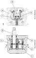
- As shown in
Figs. 1 and 1A , a gear pump generally comprises two mutually engaged toothed wheels (1, 2). The toothed wheels (1, 2) are disposed inside a case (3) in such a way to define an inlet fluid area and an outlet fluid area. - One of the toothed wheels, which is defined as driving wheel (1), receives motion from a drive shaft, whereas the other toothed wheel, which is defined as driven wheel (2), receives motion from the driving wheel (1) it engages with. The toothed wheels (1, 2) are joined to respective shafts (10, 20) revolvingly supported by supports or bushes (4, 5).
- In this description the term "front" refers to the side of the pump from which the shaft of the driving wheel protrudes, i.e. the inlet shaft that receives the rotation.
- The pump comprises a front bush (4) that revolvingly supports a front portion of the shafts of the toothed wheels and a rear bush (5) that revolvingly supports a rear portion of the shafts of the toothed wheels. Each bush is provided with two circular housings that revolvingly support a portion of the shafts of the two toothed wheels.
- A front flange (6) and a back lid (7) are fixed to the case (3) in such way to close the bushes (4, 5) and the toothed wheels (1, 2) inside a box composed of the case (3), the front flange (6) and the back lid (7). The front flange (6) is provided with an opening from which the shaft (10) of the driving wheel (1) comes out. Therefore a projecting portion (13) of the shaft of the driving wheel frontally protrudes from the front flange (6) in order to be connected to a drive shaft that transmits motion.
- Gear pumps are volumetric machines because the volume comprised between the compartments of the teeth of the two toothed wheels and the external case is transferred from the inlet area to the outlet area by means of the rotation of the toothed wheels. Different types of fluid can be used, as well as different outlet and/or inlet pressure and pump displacement values.
- The fluid used in the most typical application is oil, which is partially incompressible. Reference pressure values are typically the ambient pressure for the inlet pressure, whereas the outlet pressure reaches maximum values of 300 bar.
- As shown in the example of
Figs. 1 and 1A , the toothed wheels (1, 2) have a straight external toothing, the same dimensions and a unitary transmission ratio. - Referring to
Fig. 2 , if toothed wheels with straight toothing are used, during operation the toothed wheels transmit a transmission force (F) that can be decomposed into a radial transmission force component (Fr) (shown inFig. 2 ) directed in radial direction with respect to the axis of rotation of the toothed wheels and a transverse transmission force component (Ft) (not shown inFig. 2 ) directed in radial direction with respect to the axis of rotation of the toothed wheels. - Referring to
Fig. 2A , in these conditions, a pressure force (P) is generated in the inlet area (shown in bold in the left-hand side ofFig. 2A ), which acts on the surfaces of the toothed wheels. The resultant of the pressure force (P) can be likewise decomposed in two components: a radial pressure force component (Pr) and a transverse pressure force component (Pt). In such a case, no force in axial direction is exerted on the toothed wheels. -
- It must be noted that in order to correctly engage two helical toothed wheels with the same geometrical features, the inclination of the helix must have a discordant direction.
-
Figs. 3A ,3B ,3C and 3D disclose a gear pump with a driving wheel (1) and a driven wheel (2) with helical toothing. The use of toothed wheels with helical toothing generates axial loads or stress (Fa, Pa) during operation. The higher the helix angle βb of the helical toothing is, the higher said axial loads or stress (Fa, Pa) will be (Figs. 3A ,3B ). The generation of the axial stress (Fa, Pa) is caused by the projection of the transmission forces (Fa) and the pressure forces (Pa) acting on the sections of the toothed wheels along the axial direction. -
Fig. 3D shows the resultants (A, B) of all axial forces acting on the toothed wheels (1, 2), respectively. - If not opposed, the generation of the axial stress (A, B) considerably increases the specific pressure that is discharged on the bushes (4, 5), thus reducing both the mechanical efficiency because of losses by friction and the reliability and maximum pressure of the pump.
- The problem of balancing the axial loads can be solved in different ways.
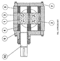
- Referring to
Fig. 4 , the use of bi-helical gears is known to solve the problem of balancing the axial loads, because the axial forces (A, B) are directly balanced on the toothed wheels. Such a solution is impaired by several drawbacks: in fact, the higher constructional complexity of the bi-helical toothed wheels, together with the higher accuracy required during the construction of the high-pressure gear pumps or motors, makes such a solution cost ineffective. - An alternative method used to balance the axial forces is disclosed in the patent
US3658452 , wherein a right-hand pump (i.e. a pump with driving shaft with clockwise rotating right-hand helix) and driven shaft with left-hand helix are used. - Referring to
Fig. 5 (which corresponds toFig. 1 ofUS3658452 ) the axial forces (A, B) acting on the driving and driven toothed wheels (11, 12) of the pump are both directed towards the back lid (16) and opposed by hydraulic pistons (51, 52) disposed at the ends of the toothed wheels, which exert contrast forces (A', B'). The hydraulic pistons (51, 52) are fed by means of passages (59, 60, 61) that connect the rear chambers (57 and 58) of the hydraulic pistons with the inlet area of the pump. The area of the hydraulic pistons (51, 52) must be suitably dimensioned in order to balance the axial forces (A, B). - The axial forces (A, B) acting on the toothed wheels are generated by the contribution of two factors: the axial component of the pressure (Pa) (
Fig. 3B ) and the axial component of the force (Fa) generated by the torque transmission from the driving wheel to the driven wheel (Fig. 3A ). Regardless of the direction of rotation and the direction of the helix used for the wheels, the forces (Pa and Fa) are always concordant on the driving wheel, whereas the forces (Pa and Fa) are always discordant on the driven wheel.

- If a pump with helical gears according to the prior art in right-hand rotation (clockwise-rotating driving shaft) is considered and a driving shaft with right-hand helix is used (
Fig. 5 ), at a known running speed, the absorbed torque at the driving shaft is:
- V = Displacement [cm3/rev]
- P = Pressure difference between inlet and outlet [bar]
- ηm = Hydro-mechanical output (experimentally obtainable value)
- Assuming that half of the torque is transferred to the fluid by the driving wheel during its pumping action, the torque transmitted to the driven wheel Mtcto is half of the total torque.

- The axial transmission force Fa generated by the helical toothed wheels is:

- Dp = Operating pitch diameter of toothed wheels [mm]
- β = Inclination angle of helix [°]
- Because of the known action and reaction principle, the force Fa acts on the driving and driven wheel with the same intensity, but with opposite direction.
- The axial force generated by the pressure Pa is the resultant of the pressure along the axial direction:

- h = Tooth height [mm]
- I = Ring width [mm]
- In view of the above, the force Pa has the same intensity and the same direction on both toothed wheels. According to the most typical dimensioning of the toothed wheels, Pa > Fa and consequently the forces F1 and F2 always have a concordant direction.
- The diameters ΦA and ΦB of the compensating pistons are obtained from the formulas (7) and (8):


- Both forces Fa and Pa linearly depend on the value of the inlet pressure P (see formulas (5) (6)). Consequently, after calculating the diameter of the compensating pistons, the axial forces are completely balanced at any value of the pressure P.
- The use of the compensating pistons is a rather inexpensive and easy-to-make solution because the work operations and the parts are simple and reliable. The precepts disclosed by the patent
US3658452 can solve the problem of balancing the axial forces only in case of monodirectional motors, in which the resultant forces A and B must be always directed towards the back lid (seeFig. 5 ), (i.e. in case of a right-hand pump with right-hand driving gear and left-hand driven gear, or in case of a left-hand pump with left-hand driving gear and right-hand driven gear). - However, some hydraulically controlled applications require the use of bi-directional or multiple stage hydraulic pumps or gears.
- The use of bidirectional pumps (with two flow directions) allows for inverting the rotation of the driving shaft, thus inverting the direction of the oil flow and the high and low pressure areas, inverting, for instance, the motion of hydraulic actuators. Likewise, the use of bidirectional motors is useful in the applications that require inverting the direction of the torque available at the outlet shaft of the hydraulic motor.
-
Fig. 6A shows the distribution of the axial forces in case of a bidirectional pump, in an operating condition in which the axial forces A and B are directed towards the front flange. In such a case, the solution disclosed inUS3658452 is not applicable because the inversion of the motion and of the inlet side with the outlet side results in the inversion of the axial forces (A, B) acting on the toothed wheels (1, 2), as shown inFig.6B . In such a case the axial forces (A, B) are directed towards the front flange (6) and not towards the back lid (7). Because of the inevitable projecting portion (13) of the shaft of the driving wheel (1) that protrudes from the front flange (6), the axial force (A) on the driving wheel (1) can no longer be balanced by means of a hydraulic piston, like in the solution shown inFig. 5 . - The same situation is found in a hydraulic motor with a high-pressure fluid inlet side and a low-pressure fluid outlet side. In such a case, there are no driving wheel and driven wheel, but simply a first toothed wheel (1) and a second toothed wheel (2). Moreover, the projecting portion of the shaft (13) is adapted to be connected to a load, not to a motor.
-
Fig. 7 shows a multiple two-stage pump comprising a front stage (SA) and a rear stage (SB). For the sake of clarity,Fig. 7 shows a two-stage pump, but the solution can be applied also to a higher number of stages. A multiple pump is necessary to connect multiple independent circuits to a single power take-off. In such a case the pumps are connected in parallel and the rear stage (SB) receives the necessary torque by means of a mechanical connection (500) (such as Oldham coupling or splined coupling), from the shaft of the driving wheel of the front stage (SA). Also in the case of multiple pumps, the solution disclosed in the patentUS3658452 is not applicable because an end portion (T) of the shaft of one of the toothed wheels of the front stage (SA) is engaged to transmit the motion to the rear stage (SB). In fact, the front stage (SA) cannot be provided with a closed back lid because the end portion (T) of the shaft of a toothed wheel must protrude in the back to transmit the motion to the rear stage (SB). - In general, the precepts disclosed by the patent
US3658452 are not applicable when the axial forces (A, B) are directed towards a side of the pump that is crossed by the shaft of a toothed wheel. - The
US 2 462 924claim 1. - The purpose of the present invention is to remedy the drawbacks of the prior art, by providing a hydraulic system to balance the axial forces in gear pumps or hydraulic motors with helical toothing of bidirectional or multiple stage type.
- This purpose is achieved according to the invention, with the characteristics claimed in the attached
independent claim 1. - Advantageous embodiments appear from the dependent claims.
- The gear pump or motor of the invention comprises:
- a first toothed wheel joined to a shaft,
- a second toothed wheel joined to a shaft and engaging with the first toothed wheel,
- supports that revolvingly support the shafts of the toothed wheels,
- a case that contains the supports and defining an inlet fluid duct and an outlet fluid duct,
- a front flange from which a protruding portion of shaft protrudes frontally, being connected to the shaft of the first toothed wheel, said protruding portion of shaft being adapted to be connected to a motor or a load, and
- a back lid fixed to the case,
- the toothing of said toothed wheels is of helical type.
- The gear pump or motor of the invention also comprises:
- an intermediate flange disposed between said case and said front flange, said intermediate flange comprising a first chamber connected by means of a connection duct to the inlet or outlet fluid duct;
- a compensating ring mounted in said first chamber of the intermediate flange and inserted on a portion of said shaft of the first toothed wheel, in such manner to compensate the axial forces imposed on the first toothed wheel and allow for motion transmission on the shaft of the first toothed wheel,
- The advantages of the compensation system of the axial forces applied to the gear pump or motor are evident. In fact, such a compensation system of the axial forces, by means of the compensating ring, allows for balancing the axial forces of the first gear and simultaneously transmitting the motion from the shaft of the first gear to another shaft.
- Additional characteristics of the invention will appear evident from the detailed description below, with reference to the attached drawings, which have an illustrative, not limitative purpose only, wherein:
-
Fig. 1 is an axial view of a gear pump with straight toothing according to the prior art; -
Fig. 1A is a cross-sectional view along section plane A-A ofFig. 1 ; -
Fig. 2 is the same view asFig. 1 , which shows the radial transmission forces; -
Fig. 2A is the same view asFig. 1A , which shows the radial and transverse pressure forces; -
Fig. 3A is an axial view of a gear pump with helical toothing, which shows the radial and axial transmission forces; -
Fig. 3B is the same view asFig. 3A , which shows the radial and axial pressure forces; -
Fig. 3C is the same view asFig. 3A , which shows the axial transmission and pressure forces when the pump is in left-hand rotation; -
Fig. 3D is the same view asFig. 3A , which shows the resultants of the axial transmission and pressure forces directed towards the back lid of the pump; -
Fig. 4 is an axial view of a bi-helical gear pump according to the prior art; -
Fig. 5 is an axial view of a helical gear pump according to the prior art, which corresponds toFig. 1 ofUS3658452 ; -
Fig. 6A is the same view asFig. 3C , which shows the axial transmission and axial pressure forces when the pump is in right-hand rotation; -
Fig. 6B is the same view asFig. 6A , which shows the resultants of the axial transmission and pressure forces directed towards the front flange of the pump; -
Fig. 7 is a diagrammatic exploded view of two stages of a multiple pump according to the prior art; -
Fig. 8 is an axial view that shows a gear pump of bi-directional type according to the present invention, wherein some high-pressure channels connected to the inlet duct of the pump are shown in bold; -
Fig. 9 is a cross-sectional view of the pump ofFig. 8 , wherein the inlet area is shown in bold; -
Fig. 10 is the same view asFig. 9 , after inverting the motion, wherein the inlet area is shown in bold; -
Fig. 11 is the same view asFig. 9 , after inverting the motion, wherein some high-pressure channels connected with the inlet duct of the pump are shown in bold; -
Fig. 11A is an axial exploded view of some elements of the compensation system of the axial thrusts of the pump ofFig. 11 ; -
Fig. 12 is an axial view of a multiple stage pump according to the present invention, comprising two stages; and -
Fig. 13 is an enlarged view of a detail ofFig. 12 , which shows the compensation system of the axial thrusts; and -
Fig. 14 is a partially axial view of a multiple stage pump according to the present invention, comprising three stages. - Referring to
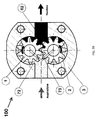
Figs. 8 to 11 , a bi-directional gear pump according to the invention is disclosed, being generally referred to with numeral (100). - Hereinafter elements that are identical or correspond to the elements described above are indicated with the same reference numbers, omitting their detailed description.
- The pump (100) comprises a first toothed wheel (1), a second toothed wheel (2), a back lid (7) in closing position and a front flange (6) from which a projecting portion (13) of the shaft protrudes frontally, being connected to the shaft (10) of the first toothed wheel (1). Both toothed wheels (1, 2) are provided with helical toothing.
- The projecting portion (13) of the shaft is connected to a motor (M) that can make a kinematic mechanism rotate in clockwise or anticlockwise direction. In such a case, the first toothed wheel (1) is the driving wheel and the second toothed wheel (2) is the driven wheel.
- With reference to
Fig. 9 , when the motor (M) makes the driving wheel (1) rotate in anticlockwise direction, an outlet area (high pressure), which is shown in bold, is generated in the left-hand side of the case (3), whereas an inlet area (low pressure) is generated in the right-hand side of the case (3). - With reference to
Fig. 8 , in such a case, respective axial forces (A, B) facing towards the back lid (7) are generated on the toothed wheels (1, 2). - The precepts of
patent US3658452 were followed to balance the axial forces (A, B) acting on the back lid (7). Two chambers (70,71) are obtained in the back lid (7), wherein a first piston (270) and a second piston (271) are disposed. The pistons (270, 271) axially actuate on the rear end border of the shafts (10, 20) of the toothed wheels (1, 2). - Two ducts (72, 73) are obtained in the back lid (7), which put the outlet chamber (shown in bold in
Fig. 9 ) of the pump in communication with the chambers (70, 71) of the two pistons (270, 271). In view of the above, the pistons (270, 271) push against the shafts (10, 20) of the toothed wheels, exercising forces (A', B') that balance the axial forces (A, B) acting on the toothed wheels. - With reference to
Fig. 10 , when the motor (M) inverts the rotation direction and puts the driving wheel (1) in clockwise rotation, an outlet area (high pressure), which is shown in bold, is generated in the right-hand side of the case (3), whereas an inlet area (low pressure) is generated in the left-hand side of the case (3). - With reference to
Fig. 11 , in such a case, respective axial forces (A, B) facing towards the front flange (6) are generated on the toothed wheels (1, 2). - An intermediate flange (8) is disposed between the case (3) and the front flange (6) in order to compensate said forces (A, B).
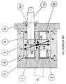
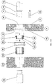
- With reference to
Fig. 11A , said intermediate flange (8) is provided with a through hole (85) in order to allow for the passage of an end portion (T) of the shaft (10) of the toothed driving wheel. - The intermediate flange (8) comprises a first chamber (80) with annular shape, obtained around the through hole (85) and a second chamber (81) with cylindrical shape, in axial position to the shaft (20) of the driven wheel (2).
- A duct (82) is obtained in the intermediate flange (82) that puts the two chambers (80, 81) in communication with the outlet duct of the pump (shown in bold in
Fig. 10 ). - A compensating ring (9) is provided in the first chamber (80). The compensating ring (9) is inserted on the end portion (T) of the shaft (10) of the driving wheel. To that end, a shoulder (15) is obtained in proximal position to the end portion (T) of the shaft of the driving wheel, against which the compensating ring (9) is stopped. Advantageously, the compensating ring (9) is splined on the end portion (T) of the shaft (10) to avoid undesired friction that may cause fluid leakage from the high-pressure area to the low-pressure area of the pump.
- The compensating ring (9) comprises a cylinder (90) and a collar (91) that radially protrudes outwards from the cylinder (90). The compensating ring (9) is internally empty and is provided with a through hole (92) to allow for the passage of the end portion (T) of the shaft of the driving wheel. The through hole (92) has a splined female section, whereas the end portion (T) of the shaft (10) has a splined male section.
- Two dynamic seals (95, 96) are disposed in the first chamber (80) of the intermediate flange (8) to support the compensating ring (9) in such way to eliminate possible leakage from the high-pressure areas to the low-pressure areas.
- A cylindrical piston (88) is disposed in the second chamber (81) of the intermediate flange.
- When the rotation direction of the toothed wheels is as shown in
Fig. 10 , the chambers (81, 80) of the intermediate flange are in communication with the outlet duct (high pressure), and consequently the fluid pushes the compensating ring (9) and the piston (88) in the direction of the arrows (A', B') (seeFig. 11 ) in such manner to compensate the axial forces (A, B) exerted on the gears. - With reference to
Fig. 11 , the collar (91) of the compensating ring has an external diameter (d1) and the cylinder (90) of the compensating ring has an external diameter (d2). - The annular area defined by the diameters d1 and d2 is such to completely compensate the axial force (A). The values of the diameters d1 and d2 are calculated with the formula (7) considering an annular section with equivalent area instead of a circular area. One of the diameters is fixed according to the constructional requirements and the other diameter is calculated with the following formula:

- The piston (88) has an external diameter (d3). The dimension (d3) of the piston (88) is such to completely compensate the axial force (B). The d3 value can be directly calculated from the following formula:

- According to a preferred embodiment of the present invention, the axial forces are balanced both on the shaft of the toothed driving wheel (1) and on the shaft of the toothed driven wheel (2), respectively by means of the compensating ring (9) and the piston (88). However, it must be considered that the resultant (A) of the axial thrusts on the shaft of the driving wheel (1) is much higher than the resultant (B) of the axial thrusts on the shaft of the driven wheel (2). Therefore the piston (88) is optional and may be omitted.
- As shown in
Figs. 8 and11 , the end portion (T) of the shaft of the driving wheel externally protrudes from the intermediate flange (8) and is connected by means of a mechanical connection (500) to a drive shaft (12) provided with said projecting portion (13) connected to the motor (M). - The mechanical connection (500) can be a splined coupling, an Oldham coupling or a coupling of any other type. The mechanical connection (500) is housed in a plate (501) that is stopped against the intermediate flange (8).
- An intermediate plate (600) whereon bearings (601) that revolvingly support the shaft (12) can be optionally provided. The intermediate plate (600) is disposed between the front flange (6) and the plate (501) that houses the mechanical connection (500).
- Although
Figs. 8 to 11 refer to a pump, said figures may also refer to a hydraulic motor wherein the pump outlet (high-pressure area) corresponds to the inlet of the motor fluid and the pump inlet (low-pressure area) corresponds to the discharge of the motor fluid. In the case of a hydraulic motor, there are no driving wheel and driven wheel, but simply a first toothed wheel (1) and a second toothed wheel (2). Moreover, the projecting portion of the shaft (13) is adapted to be connected to a load, not to a motor (M) -
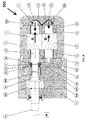
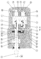
Figs. 12 ,13 illustrate a multiple gear pump (200). - The multiple gear pump (200) comprises a front stage (SA) and a rear stage (SB). Each stage comprises toothed wheels with helical toothing.
- The rear stage (SB) is the last stage of the pump and therefore is closed with the back lid (7), from which no shaft protrudes. A projecting portion (13) of the shaft frontally protrudes from the front flange (6) to be connected to a motor (M).
- The end portion (T) of the shaft of the driving toothed wheel of the front stage (SA) is connected to the end portion (T) of the shaft of the toothed driving wheel of the rear stage (SB) by means of the mechanical connection (500) housed in the plate (501) disposed between the two stages (SA, SB).
- In such a case, the toothed wheels of the front stage and of the rear stage are subject to respective axial forces (A, B, C, D), which are all directed towards the back lid (7).
- Consequently, the axial forces (C, D) on the toothed wheels of the rear stage (SB) are balanced by the action of the pistons (270, 271) disposed in the back lid (7).
- Instead, the axial forces (A, B) on the toothed wheels of the front stage (SA) are balanced by the action of the compensating ring (9) and of the piston (88) disposed in the intermediate flange (8). As shown in
Fig. 13 , the compensating ring (9) and the piston (88) generate respective axial forces (A', B') that compensate the axial forces (A, B) exerted on the toothed wheels (1, 2) of the front stage (SA). - The plate (501) that houses the mechanical connection (500) is disposed between the intermediate flange (8) and the rear stage (SB).
- Referring to
Fig. 14 , the multiple gear pump (200) may comprise one or more intermediate stages (SI) disposed between the front stage (SA) and the rear stage (SB). Each intermediate stage (SI) comprises a first toothed wheel (1) and a second toothed wheel (2) with helical toothing. The first toothed wheel (1) of the intermediate stage (SI) receives the motion from the end portion (T) of the shaft of the driving wheel (1) of the frontally positioned stage (SA) and in turn gives motion to a posterior stage (SB) by means of the mechanical connection (500) that connects the shaft of the first toothed wheel of the intermediate stage to the shaft of the first toothed wheel of the posterior stage (SB). - In such a case, an additional intermediate flange (8) is disposed between the case of the intermediate stage (SI) and the mechanical connection (500). The compensating ring (9) of the intermediate flange (8) compensates the axial thrust (A) of the first toothed wheel (1) of the intermediate stage (SI).
- Variations and modifications can be made to the present embodiments of the invention, within the reach of an expert of the field, while still falling within the scope of the invention.
Claims (11)
- A gear pump or hydraulic gear motor (100; 200) comprising- a first toothed wheel (1) joined to a shaft (10),- a second toothed wheel (2) joined to a shaft (20) and engaging with the first toothed wheel (1),- supports (4, 5) revolvingly supporting the shafts (10, 20) of the toothed wheels,- a case (3) containing the supports (4, 5) and defining an inlet fluid duct and an outlet fluid duct,- a front flange (6) from which a projecting portion (13) of shaft protrudes frontally, being connected to the shaft (10) of the first toothed wheel, said projecting portion (13) of shaft being adapted to be connected to a motor (M) or a load, and- a back lid (7) fixed to the case (3),
wherein- the toothing of said toothed wheels (1, 2) is of helical type,characterized in that it comprises:- an intermediate flange (8) disposed between said case (3) and said front flange (6), said intermediate flange (8) comprising a first chamber (80) connected by means of a connection duct (82) to the inlet or outlet fluid duct;- a compensating ring (9) mounted in said first chamber (80) of the intermediate flange and inserted on a portion (T) of said shaft (10) of the first toothed wheel, in such manner to compensate the axial forces (A) imposed on the first toothed wheel and allow for motion transmission on the shaft (10) of the first toothed wheel,wherein said compensating ring (9) comprises an internally empty cylinder (90) and a collar (91) radially protruding from the cylinder (90), wherein the external diameters (d1, d2) of cylinder (90) and collar (91) are selected in such manner to compensate the axial forces (A) imposed on the first toothed wheel. - The gear pump or hydraulic gear motor (100; 200) of claim 1, also comprising:- a second chamber (81) obtained in said intermediate flange (8) and connected by means of said connection duct (82) to the inlet or outlet fluid duct of the pump- a piston (88) mounted in said second chamber (81) of said intermediate flange in order to stop against one end of said shaft (20) of the second toothed wheel, in such manner to compensate the axial forces (B) imposed on said second toothed wheel.
- The gear pump or hydraulic gear motor (100; 200) of claim 1, wherein said portion (T) of the shaft of the first toothed wheel whereon said compensating ring (9) is inserted is an end portion (T) and the gear pump also comprises a mechanical connection (500) connecting said end portion (T) of the toothed driving wheel to another shaft (13; 10) for motion transmission.
- The gear pump or hydraulic gear motor (100; 200) of claim 1 or 2, wherein the compensating ring (9) is keyed on said portion (T) of the shaft of the driving wheel in such manner to eliminate relative friction.
- The gear pump or hydraulic gear motor (100; 200) of any one of the preceding claims, comprising dynamic seals (95, 96) disposed in said first chamber (80) of the intermediate flange (8) to support said compensating ring (9) in such manner to avoid leakage from high pressure areas towards low pressure areas.
- The gear pump or hydraulic gear motor (100; 200) of any one of the preceding claims, wherein said closing lid (7) comprises:- a first chamber (70) and a second chamber (71) connected by means of ducts (72, 73) to the inlet or outlet fluid duct;- a first piston (270) mounted in said first chamber (70) of the closing lid in order to stop against the end of the shaft (10) of the first toothed wheel (1), in such manner to compensate the axial forces (A; C) imposed on said first toothed wheel, and- a second piston (271) mounted in said second chamber (71) of the closing lid in order to stop against the end of the shaft (20) of the second toothed wheel (2), in such manner to compensate the axial forces (B; D) imposed on said second toothed wheel.
- The gear pump or hydraulic gear motor (100; 200) of any one of the preceding claims, additionally comprising a mechanical connection (500) connecting the shaft of the first toothed wheel (1) to a drive shaft (12) comprising said projecting portion (13) that protrudes from the front flange (6).
- The gear pump (100) of any one of the preceding claims, wherein said projecting portion (13) of the shaft is connected to a motor (M) in such manner that the first toothed wheel (1) is a driving wheel and the second toothed wheel (2) is a driven wheel.
- The hydraulic gear motor (200) of any one of claims 1 to 7, wherein said projecting portion (13) of the shaft is connected to a load.
- The gear pump or hydraulic gear motor (200) of any one of claims 1 to 7, wherein said gear pump or hydraulic gear motor is of multiple type and comprises- at least one front stage (SA) comprising a first toothed wheel (1) and a second toothed wheel (2),- a rear stage (SB) comprising a first toothed wheel (1) and a second toothed wheel (2) and said closing lid (7), and- a mechanical connection (500) connecting the shaft of the first toothed wheel (1) of the front stage (SA) to the shaft of the first toothed wheel (1) of the rear stage (SB),wherein said intermediate flange (8) is disposed between the case (3) of the front stage (SA) and the mechanical connection (500) and said compensating ring (9) of the intermediate flange compensates the axial thrust (A) of the first toothed wheel (1, 2) of the front stage (SA);
- The gear pump or hydraulic gear motor (200) of claim 10, also comprising at least one intermediate stage (SI) between the front stage (SA) and the rear stage (SB), each intermediate stage (SI) comprising a first toothed wheel (1) and a second toothed wheel (2) with helical toothing, the first toothed wheel (1) of the intermediate stage (SI) receiving motion from the end section (T) of the shaft of the driving wheel (1) of the front stage (SA) and moves the rear stage (SB) through a mechanical connection (500) connecting the shaft of the first toothed wheel of the intermediate stage (SI) to the shaft of the first toothed wheel of the rear stage (SB), wherein an additional intermediate flange (8) is disposed between the case of the intermediate stage (SI) and the mechanical connection (500), said additional intermediate flange (8) comprising a compensating ring (9) to compensate the axial thrust (A) of the first toothed wheel (1) of the intermediate stage (SI).
Applications Claiming Priority (2)
| Application Number | Priority Date | Filing Date | Title |
|---|---|---|---|
| IT000102A ITAN20130102A1 (en) | 2013-05-30 | 2013-05-30 | HYDRAULIC PUMP OR HYDRAULIC GEAR MOTOR WITH HELICAL TOOTH GEAR WITH HYDRAULIC SYSTEM FOR BALANCING OF AXIAL FORCES. |
| PCT/EP2014/060297 WO2014191253A1 (en) | 2013-05-30 | 2014-05-20 | Gear pump or hydraulic gear motor with helical toothing provided with hydraulic system for axial thrust balance. |
Publications (2)
| Publication Number | Publication Date |
|---|---|
| EP2859237A1 EP2859237A1 (en) | 2015-04-15 |
| EP2859237B1 true EP2859237B1 (en) | 2016-05-04 |
Family
ID=48951480
Family Applications (1)
| Application Number | Title | Priority Date | Filing Date |
|---|---|---|---|
| EP14728475.6A Active EP2859237B1 (en) | 2013-05-30 | 2014-05-20 | Gear pump or hydraulic gear motor with helical toothing provided with hydraulic system for axial thrust balance. |
Country Status (15)
| Country | Link |
|---|---|
| US (1) | US9567999B2 (en) |
| EP (1) | EP2859237B1 (en) |
| JP (1) | JP6074826B2 (en) |
| KR (1) | KR101664646B1 (en) |
| CN (1) | CN104379934B (en) |
| AU (1) | AU2014259589B2 (en) |
| DK (1) | DK2859237T3 (en) |
| ES (1) | ES2586413T3 (en) |
| HK (1) | HK1208717A1 (en) |
| IN (1) | IN2014MN02509A (en) |
| IT (1) | ITAN20130102A1 (en) |
| PL (1) | PL2859237T3 (en) |
| RU (1) | RU2598751C2 (en) |
| TW (1) | TWI621778B (en) |
| WO (1) | WO2014191253A1 (en) |
Cited By (1)
| Publication number | Priority date | Publication date | Assignee | Title |
|---|---|---|---|---|
| CN110345065A (en) * | 2018-04-05 | 2019-10-18 | 凯斯帕公司 | Pumping installations |
Families Citing this family (19)
| Publication number | Priority date | Publication date | Assignee | Title |
|---|---|---|---|---|
| KR101715677B1 (en) | 2015-09-17 | 2017-03-15 | (유)한독엘리베이터 | pressure gear pump |
| CN105805528A (en) * | 2016-03-16 | 2016-07-27 | 哈尔滨宏万智科技开发有限公司 | Gear oil pump with double transmission gear shafts |
| IT201600076227A1 (en) * | 2016-07-20 | 2018-01-20 | Settima Meccanica S R L Soc A Socio Unico | Bi-helical gear wheel with variable helix angle and non-encapsulating tooth profile for gear hydraulic equipment |
| US10808694B2 (en) * | 2016-08-15 | 2020-10-20 | Georgia Tech Research Corporation | Systems and devices for pumping and controlling high temperature fluids |
| JP6376197B2 (en) * | 2016-09-30 | 2018-08-22 | ダイキン工業株式会社 | Gear pump or gear motor |
| US10000895B2 (en) * | 2016-10-06 | 2018-06-19 | Caterpillar Inc. | Rotating hydraulic gear motor |
| CN106438680A (en) * | 2016-11-24 | 2017-02-22 | 北京航科发动机控制系统科技有限公司 | High-pressure gear pump bearing with sealing structure |
| CZ2017330A3 (en) * | 2017-06-08 | 2018-11-21 | Emil Brabec | A piston pump for liquids, especially for more viscous and pastelike media |
| CN108223361A (en) * | 2017-08-08 | 2018-06-29 | 河南航天液压气动技术有限公司 | A kind of electric fuel punp |
| DE102017218287B4 (en) * | 2017-10-12 | 2021-12-23 | Vitesco Technologies GmbH | Fuel pump and fuel delivery unit |
| CN108571445B (en) * | 2018-04-16 | 2019-08-13 | 宁波布赫懋鑫液压技术有限公司 | A kind of crescent gear pump with nose balance function |
| IT201800005956A1 (en) | 2018-06-01 | 2019-12-01 | VOLUMETRIC GEAR MACHINE WITH HELICAL TEETH | |
| US11060559B2 (en) * | 2018-06-11 | 2021-07-13 | Eaton Intelligent Power Limited | Bi-metallic journal bearing with additive manufactured sleeve |
| KR20200036183A (en) | 2018-09-28 | 2020-04-07 | 신진정밀(주) | Helical geared hydraulic pump having function for axial thrust balancing |
| CN110617213B (en) * | 2019-10-24 | 2021-06-04 | 山东大学 | Spiral tooth double-arc tooth-shaped hydraulic gear pump with dynamic and static pressure floating support at shaft end |
| RU195531U1 (en) * | 2019-11-18 | 2020-01-30 | Акционерное общество "Ярославский завод дизельной аппаратуры" | FUEL SUPPLY PUMP |
| CN111622946B (en) * | 2020-06-02 | 2022-02-01 | 安徽优源液压科技有限公司 | High-power gear oil pump |
| RU206547U1 (en) * | 2021-06-21 | 2021-09-15 | Сергей Иванович Никитин | GEAR PUMP |
| RU210280U1 (en) * | 2021-12-20 | 2022-04-05 | Сергей Иванович Никитин | GEAR PUMP |
Family Cites Families (17)
| Publication number | Priority date | Publication date | Assignee | Title |
|---|---|---|---|---|
| US2159744A (en) * | 1936-08-26 | 1939-05-23 | Brown & Sharpe Mfg | Gear pump |
| US2462924A (en) * | 1944-03-01 | 1949-03-01 | Equi Flow Inc | Gear tooth profile |
| US3164099A (en) * | 1961-08-09 | 1965-01-05 | Iyoi Hitosi | Toothed profiles of rotors of gear pump |
| US3104616A (en) * | 1961-08-14 | 1963-09-24 | Clark Equipment Co | Pressure loaded gear pump |
| US3658452A (en) * | 1969-11-18 | 1972-04-25 | Shimadzu Corp | Gear pump or motor |
| US4245969A (en) * | 1979-01-26 | 1981-01-20 | The Garrett Corporation | Pump |
| DE169307T1 (en) * | 1984-05-18 | 1986-07-24 | Nordson Corp., Amherst, Ohio | PUMP FOR HOT-MELT ADHESIVES WITH PERFORATING GEARS. |
| SE463682B (en) * | 1984-06-20 | 1991-01-07 | Imo Ab | HYDRAULIC SCREW MACHINE, PRELIMINALLY USED AS A PUMP INTENDED TO BE DOWN IN A DRILL |
| SU1629609A1 (en) * | 1989-03-30 | 1991-02-23 | Челябинский Политехнический Институт Им.Ленинского Комсомола | Adjustable gear pump |
| JPH0641755B2 (en) * | 1989-04-19 | 1994-06-01 | 日機装株式会社 | Canned inscribed gear pump |
| JP2512443Y2 (en) * | 1989-07-28 | 1996-10-02 | 帝人株式会社 | Gear pump for molten resin |
| US6887055B2 (en) * | 2002-10-25 | 2005-05-03 | Mario Antonio Morselli | Positive-displacement rotary pump |
| US20060039815A1 (en) * | 2004-08-18 | 2006-02-23 | Allan Chertok | Fluid displacement pump |
| US7300265B2 (en) * | 2005-09-12 | 2007-11-27 | Emerson Climate Technologies, Inc. | Flanged sleeve guide |
| US20070098586A1 (en) * | 2005-10-28 | 2007-05-03 | Autotronic Controls Corporation | Fuel pump |
| IT1390747B1 (en) * | 2008-08-12 | 2011-09-23 | Settima Flow Mechanisms Srl | ROTARY GEAR VOLUMETRIC PUMP |
| DE102009012853A1 (en) * | 2009-03-12 | 2010-09-16 | Robert Bosch Gmbh | Hydraulic gear machine |
-
2013
- 2013-05-30 IT IT000102A patent/ITAN20130102A1/en unknown
-
2014
- 2014-05-16 TW TW103117281A patent/TWI621778B/en active
- 2014-05-20 CN CN201480001562.6A patent/CN104379934B/en active Active
- 2014-05-20 IN IN2509MUN2014 patent/IN2014MN02509A/en unknown
- 2014-05-20 JP JP2015546067A patent/JP6074826B2/en active Active
- 2014-05-20 ES ES14728475.6T patent/ES2586413T3/en active Active
- 2014-05-20 DK DK14728475.6T patent/DK2859237T3/en active
- 2014-05-20 RU RU2015102102/06A patent/RU2598751C2/en active
- 2014-05-20 PL PL14728475.6T patent/PL2859237T3/en unknown
- 2014-05-20 EP EP14728475.6A patent/EP2859237B1/en active Active
- 2014-05-20 US US14/401,465 patent/US9567999B2/en active Active
- 2014-05-20 KR KR1020147032370A patent/KR101664646B1/en active IP Right Grant
- 2014-05-20 AU AU2014259589A patent/AU2014259589B2/en active Active
- 2014-05-20 WO PCT/EP2014/060297 patent/WO2014191253A1/en active Application Filing
-
2015
- 2015-09-24 HK HK15109372.2A patent/HK1208717A1/en unknown
Cited By (1)
| Publication number | Priority date | Publication date | Assignee | Title |
|---|---|---|---|---|
| CN110345065A (en) * | 2018-04-05 | 2019-10-18 | 凯斯帕公司 | Pumping installations |
Also Published As
| Publication number | Publication date |
|---|---|
| KR20150009973A (en) | 2015-01-27 |
| RU2598751C2 (en) | 2016-09-27 |
| BR112014030180A2 (en) | 2017-06-27 |
| RU2015102102A (en) | 2016-08-10 |
| HK1208717A1 (en) | 2016-03-11 |
| CN104379934A (en) | 2015-02-25 |
| CN104379934B (en) | 2016-08-31 |
| TW201512541A (en) | 2015-04-01 |
| IN2014MN02509A (en) | 2015-07-17 |
| EP2859237A1 (en) | 2015-04-15 |
| KR101664646B1 (en) | 2016-10-11 |
| DK2859237T3 (en) | 2016-08-15 |
| ITAN20130102A1 (en) | 2014-12-01 |
| ES2586413T3 (en) | 2016-10-14 |
| WO2014191253A1 (en) | 2014-12-04 |
| US20160265528A1 (en) | 2016-09-15 |
| AU2014259589A1 (en) | 2015-01-15 |
| US9567999B2 (en) | 2017-02-14 |
| AU2014259589B2 (en) | 2015-12-10 |
| JP6074826B2 (en) | 2017-02-08 |
| JP2016507686A (en) | 2016-03-10 |
| TWI621778B (en) | 2018-04-21 |
| PL2859237T3 (en) | 2016-11-30 |
Similar Documents
| Publication | Publication Date | Title |
|---|---|---|
| EP2859237B1 (en) | Gear pump or hydraulic gear motor with helical toothing provided with hydraulic system for axial thrust balance. | |
| RU2700840C2 (en) | Pump combined with two primary drives driven independently from each other (embodiments), and method of pump operation (embodiments) | |
| US8104375B2 (en) | Differential gear unit for motor vehicles comprising an active control mechanism for the driving force distribution | |
| KR101289498B1 (en) | Differential gear mechanism and improved axle retention arrangement therefor | |
| CN109416107B (en) | Transmission for a motor vehicle and drive train for a motor vehicle | |
| KR20060136333A (en) | Improved coupling device independent of differential speed | |
| US10487657B2 (en) | Hydraulic machine | |
| CN109424704B (en) | Transmission mechanism for single-wheel drive unit | |
| JPH07305685A (en) | Rotary gearing | |
| JP6086979B2 (en) | Gear pump | |
| US8596165B2 (en) | Multiple gear motor drive | |
| EP2954197B1 (en) | Hydraulic gear motor, gear pump and gearbox with continuously variable parameters. | |
| KR102519194B1 (en) | Limited slip differential for vehicles and electric drive apparatus including same | |
| CN107054054B (en) | Clutch device for a hybrid drive | |
| KR102519195B1 (en) | Limited slip differential for vehicles and electric drive apparatus including same | |
| BR112014030180B1 (en) | GEAR PUMP OR HYDRAULIC GEAR ENGINE WITH HELICOIDAL INDENTATION, EQUIPPED WITH HYDRAULIC SYSTEM FOR AXIAL PUSH BALANCE | |
| CN113853492B (en) | Transmission mechanism, in particular for a single-wheel drive unit | |
| US20240124049A1 (en) | Steering Transmission for Electromechanical Steering System for a Vehicle and Electromechanical Steering System for a Vehicle | |
| WO2000061947A9 (en) | Dual path hydraulic pump | |
| US20210268898A1 (en) | Hydrostatic drive system for vehicles | |
| KR20230102292A (en) | Variable speed fluid coupling be equipped with reduction gear | |
| EP2034184A2 (en) | Pumping Apparatus | |
| CN116085432A (en) | Gearbox and new energy engineering machinery | |
| US6524087B1 (en) | Hydrostatic planetary rotation machine having an orbiting rotary valve | |
| WO2017091099A1 (en) | Automotive hydraulic drive system |
Legal Events
| Date | Code | Title | Description |
|---|---|---|---|
| PUAI | Public reference made under article 153(3) epc to a published international application that has entered the european phase |
Free format text: ORIGINAL CODE: 0009012 |
|
| 17P | Request for examination filed |
Effective date: 20150109 |
|
| AK | Designated contracting states |
Kind code of ref document: A1 Designated state(s): AL AT BE BG CH CY CZ DE DK EE ES FI FR GB GR HR HU IE IS IT LI LT LU LV MC MK MT NL NO PL PT RO RS SE SI SK SM TR |
|
| AX | Request for extension of the european patent |
Extension state: BA ME |
|
| GRAP | Despatch of communication of intention to grant a patent |
Free format text: ORIGINAL CODE: EPIDOSNIGR1 |
|
| DAX | Request for extension of the european patent (deleted) | ||
| INTG | Intention to grant announced |
Effective date: 20160122 |
|
| REG | Reference to a national code |
Ref country code: HK Ref legal event code: DE Ref document number: 1208717 Country of ref document: HK |
|
| GRAS | Grant fee paid |
Free format text: ORIGINAL CODE: EPIDOSNIGR3 |
|
| GRAA | (expected) grant |
Free format text: ORIGINAL CODE: 0009210 |
|
| AK | Designated contracting states |
Kind code of ref document: B1 Designated state(s): AL AT BE BG CH CY CZ DE DK EE ES FI FR GB GR HR HU IE IS IT LI LT LU LV MC MK MT NL NO PL PT RO RS SE SI SK SM TR |
|
| REG | Reference to a national code |
Ref country code: GB Ref legal event code: FG4D |
|
| REG | Reference to a national code |
Ref country code: CH Ref legal event code: EP |
|
| REG | Reference to a national code |
Ref country code: AT Ref legal event code: REF Ref document number: 797157 Country of ref document: AT Kind code of ref document: T Effective date: 20160515 |
|
| REG | Reference to a national code |
Ref country code: FR Ref legal event code: PLFP Year of fee payment: 3 |
|
| REG | Reference to a national code |
Ref country code: IE Ref legal event code: FG4D |
|
| REG | Reference to a national code |
Ref country code: DE Ref legal event code: R096 Ref document number: 602014001824 Country of ref document: DE |
|
| REG | Reference to a national code |
Ref country code: RO Ref legal event code: EPE |
|
| REG | Reference to a national code |
Ref country code: DK Ref legal event code: T3 Effective date: 20160802 |
|
| REG | Reference to a national code |
Ref country code: SE Ref legal event code: TRGR |
|
| REG | Reference to a national code |
Ref country code: NL Ref legal event code: FP |
|
| REG | Reference to a national code |
Ref country code: LT Ref legal event code: MG4D |
|
| REG | Reference to a national code |
Ref country code: CH Ref legal event code: NV Representative=s name: OFFICE ERNEST T. FREYLINGER S.A., CH |
|
| REG | Reference to a national code |
Ref country code: NO Ref legal event code: T2 Effective date: 20160504 |
|
| REG | Reference to a national code |
Ref country code: ES Ref legal event code: FG2A Ref document number: 2586413 Country of ref document: ES Kind code of ref document: T3 Effective date: 20161014 |
|
| PG25 | Lapsed in a contracting state [announced via postgrant information from national office to epo] |
Ref country code: LT Free format text: LAPSE BECAUSE OF FAILURE TO SUBMIT A TRANSLATION OF THE DESCRIPTION OR TO PAY THE FEE WITHIN THE PRESCRIBED TIME-LIMIT Effective date: 20160504 Ref country code: FI Free format text: LAPSE BECAUSE OF FAILURE TO SUBMIT A TRANSLATION OF THE DESCRIPTION OR TO PAY THE FEE WITHIN THE PRESCRIBED TIME-LIMIT Effective date: 20160504 |
|
| PG25 | Lapsed in a contracting state [announced via postgrant information from national office to epo] |
Ref country code: RS Free format text: LAPSE BECAUSE OF FAILURE TO SUBMIT A TRANSLATION OF THE DESCRIPTION OR TO PAY THE FEE WITHIN THE PRESCRIBED TIME-LIMIT Effective date: 20160504 Ref country code: HR Free format text: LAPSE BECAUSE OF FAILURE TO SUBMIT A TRANSLATION OF THE DESCRIPTION OR TO PAY THE FEE WITHIN THE PRESCRIBED TIME-LIMIT Effective date: 20160504 Ref country code: PT Free format text: LAPSE BECAUSE OF FAILURE TO SUBMIT A TRANSLATION OF THE DESCRIPTION OR TO PAY THE FEE WITHIN THE PRESCRIBED TIME-LIMIT Effective date: 20160905 Ref country code: GR Free format text: LAPSE BECAUSE OF FAILURE TO SUBMIT A TRANSLATION OF THE DESCRIPTION OR TO PAY THE FEE WITHIN THE PRESCRIBED TIME-LIMIT Effective date: 20160805 Ref country code: LV Free format text: LAPSE BECAUSE OF FAILURE TO SUBMIT A TRANSLATION OF THE DESCRIPTION OR TO PAY THE FEE WITHIN THE PRESCRIBED TIME-LIMIT Effective date: 20160504 |
|
| PG25 | Lapsed in a contracting state [announced via postgrant information from national office to epo] |
Ref country code: SK Free format text: LAPSE BECAUSE OF FAILURE TO SUBMIT A TRANSLATION OF THE DESCRIPTION OR TO PAY THE FEE WITHIN THE PRESCRIBED TIME-LIMIT Effective date: 20160504 Ref country code: EE Free format text: LAPSE BECAUSE OF FAILURE TO SUBMIT A TRANSLATION OF THE DESCRIPTION OR TO PAY THE FEE WITHIN THE PRESCRIBED TIME-LIMIT Effective date: 20160504 |
|
| REG | Reference to a national code |
Ref country code: DE Ref legal event code: R097 Ref document number: 602014001824 Country of ref document: DE |
|
| PG25 | Lapsed in a contracting state [announced via postgrant information from national office to epo] |
Ref country code: SM Free format text: LAPSE BECAUSE OF FAILURE TO SUBMIT A TRANSLATION OF THE DESCRIPTION OR TO PAY THE FEE WITHIN THE PRESCRIBED TIME-LIMIT Effective date: 20160504 |
|
| PLBE | No opposition filed within time limit |
Free format text: ORIGINAL CODE: 0009261 |
|
| STAA | Information on the status of an ep patent application or granted ep patent |
Free format text: STATUS: NO OPPOSITION FILED WITHIN TIME LIMIT |
|
| 26N | No opposition filed |
Effective date: 20170207 |
|
| REG | Reference to a national code |
Ref country code: FR Ref legal event code: PLFP Year of fee payment: 4 |
|
| PG25 | Lapsed in a contracting state [announced via postgrant information from national office to epo] |
Ref country code: SI Free format text: LAPSE BECAUSE OF FAILURE TO SUBMIT A TRANSLATION OF THE DESCRIPTION OR TO PAY THE FEE WITHIN THE PRESCRIBED TIME-LIMIT Effective date: 20160504 |
|
| REG | Reference to a national code |
Ref country code: HK Ref legal event code: GR Ref document number: 1208717 Country of ref document: HK |
|
| REG | Reference to a national code |
Ref country code: FR Ref legal event code: PLFP Year of fee payment: 5 |
|
| PG25 | Lapsed in a contracting state [announced via postgrant information from national office to epo] |
Ref country code: HU Free format text: LAPSE BECAUSE OF FAILURE TO SUBMIT A TRANSLATION OF THE DESCRIPTION OR TO PAY THE FEE WITHIN THE PRESCRIBED TIME-LIMIT; INVALID AB INITIO Effective date: 20140520 |
|
| PG25 | Lapsed in a contracting state [announced via postgrant information from national office to epo] |
Ref country code: MT Free format text: LAPSE BECAUSE OF NON-PAYMENT OF DUE FEES Effective date: 20160531 Ref country code: CY Free format text: LAPSE BECAUSE OF FAILURE TO SUBMIT A TRANSLATION OF THE DESCRIPTION OR TO PAY THE FEE WITHIN THE PRESCRIBED TIME-LIMIT Effective date: 20160504 Ref country code: MK Free format text: LAPSE BECAUSE OF FAILURE TO SUBMIT A TRANSLATION OF THE DESCRIPTION OR TO PAY THE FEE WITHIN THE PRESCRIBED TIME-LIMIT Effective date: 20160504 Ref country code: IS Free format text: LAPSE BECAUSE OF FAILURE TO SUBMIT A TRANSLATION OF THE DESCRIPTION OR TO PAY THE FEE WITHIN THE PRESCRIBED TIME-LIMIT Effective date: 20160504 |
|
| PG25 | Lapsed in a contracting state [announced via postgrant information from national office to epo] |
Ref country code: AL Free format text: LAPSE BECAUSE OF FAILURE TO SUBMIT A TRANSLATION OF THE DESCRIPTION OR TO PAY THE FEE WITHIN THE PRESCRIBED TIME-LIMIT Effective date: 20160504 |
|
| REG | Reference to a national code |
Ref country code: AT Ref legal event code: UEP Ref document number: 797157 Country of ref document: AT Kind code of ref document: T Effective date: 20160504 |
|
| REG | Reference to a national code |
Ref country code: DE Ref legal event code: R081 Ref document number: 602014001824 Country of ref document: DE Owner name: MARZOCCHI POMPE S.P.A., IT Free format text: FORMER OWNER: MARZOCCHI POMPE S.P.A., CASALECCHIO DI RENO, IT |
|
| REG | Reference to a national code |
Ref country code: LU Ref legal event code: HC Owner name: MARZOCCHI POMPE S.P.A.; IT Free format text: FORMER OWNER: MARZOCCHI POMPE S.P.A. Effective date: 20211012 |
|
| REG | Reference to a national code |
Ref country code: NO Ref legal event code: CHAD Owner name: MARZOCCHI POMPE S.P.A., IT |
|
| P01 | Opt-out of the competence of the unified patent court (upc) registered |
Effective date: 20230510 |
|
| PGFP | Annual fee paid to national office [announced via postgrant information from national office to epo] |
Ref country code: LU Payment date: 20230525 Year of fee payment: 10 |
|
| PGFP | Annual fee paid to national office [announced via postgrant information from national office to epo] |
Ref country code: RO Payment date: 20230510 Year of fee payment: 10 Ref country code: NO Payment date: 20230519 Year of fee payment: 10 Ref country code: NL Payment date: 20230525 Year of fee payment: 10 Ref country code: MC Payment date: 20230522 Year of fee payment: 10 Ref country code: IT Payment date: 20230505 Year of fee payment: 10 Ref country code: IE Payment date: 20230518 Year of fee payment: 10 Ref country code: FR Payment date: 20230523 Year of fee payment: 10 Ref country code: ES Payment date: 20230613 Year of fee payment: 10 Ref country code: DK Payment date: 20230524 Year of fee payment: 10 Ref country code: DE Payment date: 20230530 Year of fee payment: 10 Ref country code: CZ Payment date: 20230517 Year of fee payment: 10 Ref country code: CH Payment date: 20230602 Year of fee payment: 10 Ref country code: BG Payment date: 20230525 Year of fee payment: 10 |
|
| PGFP | Annual fee paid to national office [announced via postgrant information from national office to epo] |
Ref country code: TR Payment date: 20230509 Year of fee payment: 10 Ref country code: SE Payment date: 20230524 Year of fee payment: 10 Ref country code: PL Payment date: 20230511 Year of fee payment: 10 Ref country code: AT Payment date: 20230519 Year of fee payment: 10 |
|
| PGFP | Annual fee paid to national office [announced via postgrant information from national office to epo] |
Ref country code: BE Payment date: 20230525 Year of fee payment: 10 |
|
| PGFP | Annual fee paid to national office [announced via postgrant information from national office to epo] |
Ref country code: GB Payment date: 20230523 Year of fee payment: 10 |