EP2858606B1 - Orthese - Google Patents
Orthese Download PDFInfo
- Publication number
- EP2858606B1 EP2858606B1 EP13728962.5A EP13728962A EP2858606B1 EP 2858606 B1 EP2858606 B1 EP 2858606B1 EP 13728962 A EP13728962 A EP 13728962A EP 2858606 B1 EP2858606 B1 EP 2858606B1
- Authority
- EP
- European Patent Office
- Prior art keywords
- orthosis
- pockets
- support area
- fastening means
- connecting element
- Prior art date
- Legal status (The legal status is an assumption and is not a legal conclusion. Google has not performed a legal analysis and makes no representation as to the accuracy of the status listed.)
- Active
Links
- 230000000284 resting effect Effects 0.000 claims 2
- 210000003414 extremity Anatomy 0.000 description 25
- 210000002683 foot Anatomy 0.000 description 9
- 210000002414 leg Anatomy 0.000 description 5
- 210000001699 lower leg Anatomy 0.000 description 5
- 238000011161 development Methods 0.000 description 4
- 230000018109 developmental process Effects 0.000 description 4
- 210000001503 joint Anatomy 0.000 description 3
- 239000000463 material Substances 0.000 description 3
- 230000015572 biosynthetic process Effects 0.000 description 2
- 238000006073 displacement reaction Methods 0.000 description 2
- 230000000694 effects Effects 0.000 description 2
- 238000005755 formation reaction Methods 0.000 description 2
- 230000033001 locomotion Effects 0.000 description 2
- 230000002441 reversible effect Effects 0.000 description 2
- 210000002303 tibia Anatomy 0.000 description 2
- 238000009423 ventilation Methods 0.000 description 2
- 229920002430 Fibre-reinforced plastic Polymers 0.000 description 1
- 206010033799 Paralysis Diseases 0.000 description 1
- 208000006011 Stroke Diseases 0.000 description 1
- 230000006978 adaptation Effects 0.000 description 1
- 238000004026 adhesive bonding Methods 0.000 description 1
- 210000003423 ankle Anatomy 0.000 description 1
- 210000000544 articulatio talocruralis Anatomy 0.000 description 1
- 244000309466 calf Species 0.000 description 1
- 210000000038 chest Anatomy 0.000 description 1
- 238000010276 construction Methods 0.000 description 1
- 239000011151 fibre-reinforced plastic Substances 0.000 description 1
- 210000003127 knee Anatomy 0.000 description 1
- 238000004519 manufacturing process Methods 0.000 description 1
- 210000003789 metatarsus Anatomy 0.000 description 1
- 238000000465 moulding Methods 0.000 description 1
- 230000036316 preload Effects 0.000 description 1
- 230000001012 protector Effects 0.000 description 1
- 238000009958 sewing Methods 0.000 description 1
- 238000004904 shortening Methods 0.000 description 1
- 208000011580 syndromic disease Diseases 0.000 description 1
- 239000004753 textile Substances 0.000 description 1
- 210000000689 upper leg Anatomy 0.000 description 1
- 230000003313 weakening effect Effects 0.000 description 1
- 238000003466 welding Methods 0.000 description 1
Images


Classifications
-
- A—HUMAN NECESSITIES
- A61—MEDICAL OR VETERINARY SCIENCE; HYGIENE
- A61F—FILTERS IMPLANTABLE INTO BLOOD VESSELS; PROSTHESES; DEVICES PROVIDING PATENCY TO, OR PREVENTING COLLAPSING OF, TUBULAR STRUCTURES OF THE BODY, e.g. STENTS; ORTHOPAEDIC, NURSING OR CONTRACEPTIVE DEVICES; FOMENTATION; TREATMENT OR PROTECTION OF EYES OR EARS; BANDAGES, DRESSINGS OR ABSORBENT PADS; FIRST-AID KITS
- A61F5/00—Orthopaedic methods or devices for non-surgical treatment of bones or joints; Nursing devices; Anti-rape devices
- A61F5/01—Orthopaedic devices, e.g. splints, casts or braces
- A61F5/0102—Orthopaedic devices, e.g. splints, casts or braces specially adapted for correcting deformities of the limbs or for supporting them; Ortheses, e.g. with articulations
- A61F5/0127—Orthopaedic devices, e.g. splints, casts or braces specially adapted for correcting deformities of the limbs or for supporting them; Ortheses, e.g. with articulations for the feet
-
- A—HUMAN NECESSITIES
- A61—MEDICAL OR VETERINARY SCIENCE; HYGIENE
- A61F—FILTERS IMPLANTABLE INTO BLOOD VESSELS; PROSTHESES; DEVICES PROVIDING PATENCY TO, OR PREVENTING COLLAPSING OF, TUBULAR STRUCTURES OF THE BODY, e.g. STENTS; ORTHOPAEDIC, NURSING OR CONTRACEPTIVE DEVICES; FOMENTATION; TREATMENT OR PROTECTION OF EYES OR EARS; BANDAGES, DRESSINGS OR ABSORBENT PADS; FIRST-AID KITS
- A61F5/00—Orthopaedic methods or devices for non-surgical treatment of bones or joints; Nursing devices; Anti-rape devices
- A61F5/01—Orthopaedic devices, e.g. splints, casts or braces
Definitions
- the invention relates to an orthosis with a support area which has fastening means in order to apply the orthosis to a limb, the support area having oppositely oriented receiving areas which are provided medially and laterally.
- Orthoses are used to stabilize limbs and can be arranged across joints. Orthoses are used, among other things, to ensure or support a desired sequence of movements, to support the supporting apparatus, to limit the range of motion of joints or to apply a certain force to a limb.
- fastening means are used, which are usually designed as straps or belts. These straps or belts are attached to frame parts, for example glued or riveted.
- the WO 2009/092348 A1 relates to an arm abduction orthosis with a body frame provided for support on the thorax of an orthotic user, on which fastening means for fixing the body frame to the orthotic user are arranged.
- a support device for supporting an arm of the orthotic user is hingedly attached to the body frame.
- the frame is fixed to the support device using fasteners.
- the support device has a support frame with two spaced-apart frame profiles, between which a support material is arranged, the support frame being supported on the body frame via at least one support element.
- the US-A-5,584,072 relates to a hip protector with a hip belt and a thigh belt, which are connected to one another via a cushion holder.
- Soft upholstery cushions can be incorporated or inserted into the upholstery receptacle.
- the US 2011/0306911 A1 relates to a knee orthosis with medially and laterally arranged support rails, each of which has two legs that are articulated to one another.
- the support rails are on the outside of an elastic base body set in pockets, the opening of which face each other.
- the WO 02/083040 A1 which discloses the preamble of claim 1, relates to an ankle-foot orthosis having a foot part in the upwardly extending strut which is connected to the footplate and attachment means for attaching the orthosis to a leg.
- the strut forks into two branches that are located on either side of the tibia.
- the orthosis is held on the leg by means of a strap that is attached to the two upper ends of the branches with a Velcro fastener. The strap is fixed on itself.
- the U.S. 2,712,310 A relates to an orthosis for a fall-foot syndrome with a foot shell which is worn in a shoe from which two lateral spring rods extend medially and laterally along one leg.
- the upper ends of the spring bars are inserted into downwardly open pockets which are sewn onto a belt that encircles a lower leg.
- the object of the present invention is to provide an orthosis which is easy to manufacture and clean and which ensures that the orthosis is securely attached to the limb.
- the orthosis according to the invention with a support area which has fastening means to apply the orthosis to a limb, provides that the support area has oppositely oriented, medially and laterally provided receiving areas, for example in the form of projections, and that on the fastening means pockets for receiving the receiving areas are arranged.
- the pockets are connected to one another via a reversibly fixable connecting element; this connecting element is preferably guided over the support area, so that the pockets and thus the fastening means are prevented from slipping down from the receiving areas.
- Receiving areas or projections are positive locking elements formed on the dimensionally stable support area of the orthosis, which can be inserted into pockets that are arranged on the fastening means, the connecting element being designed as a belt wrapping around the support area and the limbs.
- the pockets enable, on the one hand, a secure fixing of the fastening means due to the opposing orientation of the projections and, on the other hand, a simple removal of the fastening means from the support area by removing the receiving areas from the pockets and removing the fastening means. This makes it possible, for example, to wash the fastening means or to use alternative fastening means that are better adapted to the shape of the limb, for example.
- the fastening means is advantageously part of a padding or has padding which is arranged on the side of the orthosis facing the pad. In this way, on the one hand, the fixing of the orthosis on the limb is secured and, on the other hand, the fixing of the padding on the support area.
- the reversible arrangement of the upholstery on the support area has the advantage that the upholstery can also be exchanged and adapted to the wishes or circumstances of the respective patient.
- the pockets are advantageously arranged medially and laterally so that it is easier to put on the orthosis.
- a further development of the invention provides that the laterally arranged pockets and / or receiving areas are longer than the medially arranged pockets and / or receiving areas. This ensures that when the crop is guided from medial to lateral, the forces acting in the circumferential direction result in the laterally formed receiving areas not being able to slide out of the pockets.
- the arrangement with laterally deeper pockets and longer receiving areas has the effect that even in the event of a rotation in the circumferential direction by the length of the medial receiving areas or medial pockets and the lateral receiving areas continue to remain in the lateral pockets. This prevents the receiving areas from being pulled out of the pockets.
- the support area is advantageously designed in the manner of a shell or channel, so that an essentially flat contact is formed around the limb.
- the shell-like or channel-like configuration makes it possible to simply place the orthosis on the limb and then to fix it to the limb using the fastening means.
- the shell-like or channel-like configuration can be provided with openings in order to enable ventilation and possibly to save weight.
- a further development of the invention provides that the connecting element is designed to be elastic, thereby enabling the pockets to be pretensioned towards one another.
- the preload is achieved when the connecting element is stretched before the fastening of the connecting element on the pockets.
- the pockets are then drawn onto the receiving areas and held there under a bias.
- the connecting element can be part of the fastening means, for example a pocket can be formed by the connecting element, for example a medially arranged pocket, so that the connecting element can be guided over the support element on the outside.
- the receiving areas are arranged between the connecting element and the fastening means and pushed into the pocket formed by the connecting element and the fastening means.
- a fixing device for the connecting element can be arranged on the outside of at least one pocket, for example in the form of fleece and hook areas.
- the connecting element can be designed as a belt wrapping around the support area and the limbs without having a fixing device on the outside a pocket is set.
- the connecting element bridges a free space between the receiving areas from lateral to medial.
- the belt guide thus runs from the medial pocket via the lateral pocket back to the medial pocket or the medial projection, as a result of which the limb is completely wrapped around.
- the free space between the receiving areas is the space into which the limb is inserted.
- the longitudinal extension of the support area which generally corresponds to the longitudinal extension of the limb, can be designed to be elastic around an axis parallel to the longitudinal extension, so that the support area can be adapted in the medial direction and in the lateral direction. Deformations going beyond this are advantageously not permitted by the support area, so that a secure support of the support area and thus the fixing of the orthosis to the limbs are possible.
- the orthosis furthermore has a support area which is connected to the support area and is supported on the limb.
- the support area is advantageously arranged across the joints, so that, for example, in the case of a foot orthosis, the support area is that area on which the foot is placed, while the support area is that area of the orthosis that is supported on the lower leg.
- the support area and the support area can be connected to one another in an articulated manner, alternatively it is provided that a more or less rigid connection is present between the two areas, whereby a relative displacement of the support area to the support area is possible within the scope of the material elasticity.
- the receiving areas can be designed as projections.
- the receiving areas enable the pockets to be fixed on the orthosis by inserting these areas into the pockets. It can be medial and lateral respectively a receiving area or projection or also several receiving areas or projections can be provided, so that either one pocket or several pockets are present medially and laterally.
- the receiving areas extend medially and laterally to the rear from the support area so that they can be received in the pockets. If the support area is designed like a channel and has straight-walled edges, the receiving areas are designed as projections which protrude and protrude from the edges. It is also possible and envisaged that the respective receiving area is formed by a molding that adjoins the support area.
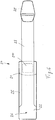
- an orthosis in the form of a so-called ankle-foot orthosis is shown, with a support area 10, a fastening means 20 and a support area 30 which is connected to the support area 10 via a connecting element 40.
- the connecting element 40 is designed as a dimensionally stable, essentially rigid element that allows only a slight displacement of the support area 10 relative to the support area 30.
- the support area 30 and the support area 10 are coupled to one another via an articulated connection, which is designed, for example, as a spring, in which the predominant deformation in the sagittal plane when a load is in the anterior-posterior direction in an area around the natural ankle joint.
- the support area 30 is designed as a flat sole plate which essentially follows the outer contour of a foot or a shoe.
- the illustrated embodiment is formed in one piece from a fiber-reinforced plastic.
- the support area 10 rests against the shin of the orthotic user and at least partially encloses the shin medially and laterally.
- the contour of the support area 10 is essentially channel-shaped or shell-shaped and can have recesses or perforations in order to enable improved ventilation of the shin bone area.
- the fastening means 20 is arranged, which is also provided with padding 25 so that the hard, shell-like construction of the support area 10 does not come into direct contact with the lower leg comes.
- both medially and laterally receiving areas 11, 12 in the form of projections or tabs are arranged, which in the Figure 1 cannot be seen.
- the receiving areas 11, 12 or projections are formed at the proximal end and distal end of the support area 10 and, when in the applied state, point backwards for the orthotic user.
- the receiving areas 11, 12 are referred to as projections, which is also to be understood as a design in which formations adjoining the supporting area 10 are suitable to be accommodated in pockets 21, 22 in order to effect a form-fitting fixation of the upholstery.
- FIG 2 is the orthosis 1 according to Figure 1 shown in an open, non-applied state, in which the two receiving areas 12 formed as projections from a vertical line of the support area 10 are shown on the medial side as a dashed line. Corresponding receiving areas 11 and pockets 21 are provided on the lateral side of the support area 10.
- fastening means 20 On the fastening means 20 pockets 21, 22 are formed, into which the projections 11, 12 are inserted. By pushing the projections 11, 12 into the pockets 21, 22, the fastening means 20 is fixed on the support area 10.
- the lateral pockets 21 are deeper than the medial pockets 22, and it is also provided that the lateral projections 11 are longer than the medial projections 12, the depth of the pockets 21, 22 being equal to the lengths of the projections 11, 12 corresponds.
- the exemplary embodiment provides two pockets 21, 22 and two projections 11, 12 medially and laterally, which are offset from one another in the longitudinal direction so that two proximal and two distal pairings of pockets 21, 22 and projections 11, 12 result.
- only one pocket can be provided medially and laterally and fixed to a corresponding receiving area.
- connecting elements 23, 24 are provided both on the proximal edge and on the distal edge of the support area 10, by means of which the orthosis 1 is fixed to the limb.
- the connecting elements 23, 24 are fastened on the medial side to the fastening means 20 with the formation of the medial pockets 22, for example welded, glued or sewn on.
- the connecting element 23, 24 embodied as a belt is guided along the outside of the support area 10 and is fixed on the outside of the lateral pocket 21, for example by means of a Velcro fastener.
- the medial and lateral pockets 21, 22 are pretensioned towards one another in the circumferential direction, so that the pockets 21, 22, which are open to the front, cannot slide down from the rearward-facing projections 11, 12 .
- the respective connecting element 23, 24 is then guided around the rear of the limb, not shown, from lateral to medial and fixed there on a fixing device 26, 27.
- the connecting element 23, 24 is thus guided once around the orthosis and the limb, the free end being fixed on the outside of the medial pocket.
- connecting elements 23, 24 for example, locking elements 28, 29 in the form of removable Velcro elements are attached, which can be fixed on the outside of the locking element 23, 24 or on fleece areas of the fixing devices 26, 27 on the outside of the medial pockets 22.
- the fixing on the connecting elements 23, 24 and on the fixing devices 26, 27 is reversible.
- the connecting elements 23, 24 can be flexible and be inelastic, flexible and elastic as well as only regionally elastic; it is also possible for the connecting element 23, 24 to be reversibly fixed to the fastening means 20, for example by means of Velcro fasteners.
- the connecting element 23, 24 bridges the free space within the shell-like support area 10 from lateral to medial.
- the support area 10 can allow the projections 11, 12 to be deformed towards one another, so that an adaptation to the dimensions of the limb on which the orthosis is to be placed can take place.
- the setting can take place via the circumferential force applied via the connecting elements 23, 24.
- the embodiment shown is particularly advantageous for patients who are paralyzed on one side or who are weakened on one side. If the connecting element 23 is guided from medial to lateral, stretched and fixed under tension on a lateral pocket 21, the orthosis can be securely fixed using the hand that is not affected by the weakening, in that the connecting element 23, 24 is then passed through and behind the limb there is a locking on the medial side.
- the fastening means 20 can also be designed as a one-piece element or as a multi-part, permanently interconnected element that has a cushioning function.
- the medial and lateral projections 11, 12 form auto-adaptive side wings which automatically adapt to the shape of the limb as a result of the circumferential force applied by the connecting element 23, 24.
- the orthotic user can grip the connecting element 23, 24 from the side with the unaffected side while sitting and simply pull it medially and there on the hooks and Velcro areas 26, 27 are set.
- FIG. 3 a variant of the invention is shown.
- the support area 10 and the support area 30 are connected to one another by a separate connecting element 40.
- the support area 30 provides elevations 35 on the edge, which prevent the foot from slipping medially and laterally from the support area 30.
- the elevations 35 are formed beginning in the area of the metatarsus and extend into the heel area in order to avoid slipping out to the rear if necessary.
- the connecting element 40 is designed as a spring to allow the support area 10 to be displaced relative to the support area 30, for example when walking, the spring action of the connecting element 40 moving the foot of the orthotic user back into the starting position after relief.
- the fastening means 20 according to FIG Figures 1 and 2 not shown.
- the entire rearwardly facing edge of the support area 10 is designed as a respective receiving area 11, 12.
- the medial and lateral pocket 22, 21 of the fastening means 20, not shown, thus accommodates an edge of the support area 10 extending over the entire height, so that a total of two pockets 21, 22 are present on the lateral side of the fastening means 20, which the rearward the ends of the support area 10 showing.
- the connecting elements 23, 24 can be arranged at different heights of the fastening means, that is, a proximal connecting means 23 and a distal connecting means 24.
- a proximal connecting means 23 and a distal connecting means 24.
- only one connecting means is provided, which is from the medial side frontally over the support area and the lateral Side of the support area is guided posteriorly around the lower leg in order to then be fixed again on the lateral side of the fastening means 20.
- the orthosis 1 has a support area 30 in the form of a flat sole for a foot or shoe, a spring element as a connecting element 40 and a support area 10 which is designed dorsally so that the support area 10 abuts occurs on the calf and not on the shin of the orthotic user.
- the orthotic 1 is designed in one piece; there is basically the possibility that the connecting element 40, the support area 30 and the support area 10 are designed separately and are connected to one another for the assembly of the orthotic 1.
- the upholstery 25 is arranged, which lies in front of the U-shaped, forwardly open support area 10 and cushions the possibly sharp edges of the dimensionally stable material.
- the padding 25 can protrude at the edges of the support area 10.
- the connecting element 40 is arranged medially on the support area and runs obliquely dorsally and proximally from the arch of the foot, that is obliquely backwards and upwards, and is guided upwards dorsally on the leg, the ankle area advantageously being left free.
- the fastening means 20 is fixed to receiving areas 11, 12 of the support area 10 via pockets 21, 22.
- the lateral receiving area 11 and the lateral pocket 21 are shown.
- the front end of the support area 10 is inserted into a pocket of the fastening means 20.
- the medial pocket is formed from the padding 25 and the connecting element 23 sewn, welded or glued onto it.
- the connecting element 23 is then led around dorsally on the outside of the support area 10 and fixed to a Velcro fastener 210 on the outside of the lateral pocket 21. This fixation can take place under a pretensioning of the elastically formed connecting element 23, so that the fastening means 20 via the pockets 21 on the support areas 11 is set securely and permanently.
- the then still open entry for the lower leg is then closed by the connecting element 23, which is passed over the shin of the orthotic user and is fixed with the locking element 28 on the medial outside of the fastening means 20, for example a fleece area on the outside of the medial pocket.
- FIG. 5 shows the fastening means 20 in an individual representation spread out flat.
- the padding 25 as a base is provided with the connecting element 23 on the outside.
- the connecting element 23 has at its in the Figure 5 left end on a spread that corresponds to the width of the padding 25.
- the connecting element 23 is attached to the upholstery 25 at the edges, so that a pocket 22 is formed for receiving the receiving area (not shown).
- a fixing device 26 in the form of a Velcro fastener or a fleece area can be arranged and designed on the outside of the pocket 22 in order to fix the locking element 28 attached to the opposite end thereon on the outside.
- the connecting element 23 extends in the direction of the other end of the upholstery 25, on which a separate pocket 21 is formed by sewing, welding or gluing a textile or the like.
- a closure element 210 in the form of a Velcro fastener is applied, fastened or formed in order to fix the connecting element 23, which is provided with a fleece layer, for example.
- the locking element 23, which is designed as a Y-element is fixed via a further Velcro fastener, so that the connecting element 23, which is provided with a fleece layer on both sides, can be received and fixed by the locking elements designed as hook elements on the locking element 28.
Description
- Die Erfindung betrifft eine Orthese mit einem Abstützbereich, der Befestigungsmittel aufweist, um die Orthese an einer Gliedmaße anzulegen, wobei der Abstützbereich einander entgegengesetzt orientierte Aufnahmebereiche aufweist, die medial und lateral vorgesehen sind..
- Orthesen dienen zur Stabilisierung von Gliedmaßen und können gelenkübergreifend angeordnet sein. Orthesen dienen unter anderem zur Sicherstellung oder Unterstützung eines gewünschten Bewegungsablaufes, zur Unterstützung des Stützapparates, zur Begrenzung des Bewegungsumfanges von Gelenken oder zur Beaufschlagung einer Gliedmaße mit einer bestimmten Kraft. Zur Festlegung einer Orthese an einer Gliedmaße werden Befestigungsmittel eingesetzt, die in der Regel als Riemen oder Gurt ausgebildet sind. Diese Riemen oder Gurte sind an Rahmenteilen befestigt, beispielsweise angeklebt oder vernietet.
- Die
WO 2009/092348 A1 betrifft eine Armabduktionsorthese mit einem zur Abstützung an dem Thorax eines Orthesennutzers vorgesehenen Körperrahmen, an dem Befestigungsmittel zur Fixierung des Körperrahmens an dem Orthesennutzer angeordnet sind. Eine Auflageeinrichtung zur Auflage eines Armes des Orthesennutzers ist gelenkig an dem Körperrahmen befestigt. Der Rahmen wird über Befestigungsmittel an der Auflageeinrichtung festgelegt. Die Auflageeinrichtung weist einen Abstützurahmen mit zwei zueinander beabstandeten Rahmenprofilen auf, zwischen denen ein Auflagematerial angeordnet ist, wobei sich der Abstützrahmen an dem Körperrahmen über zumindest ein Stützelement abstützt. - Die
US-A-5,584,072 betrifft einen Hüftschutz mit einem Hüftgurt und einem Oberschenkelgurt, die über eine Polsteraufnahme miteinander verbunden sind. In der Polsteraufnahme können weiche Polsterkissen eingearbeitet oder eingesteckt sein. - Die
US 2011/0306911 A1 betrifft eine Knieorthese mit medial und lateral angeordneten Stützschienen, die jeweils zwei gelenkig miteinander verbundene Schenkel aufweisen. Die Stützschienen sind auf der Außenseite eines elastischen Grundkörpers in Taschen festgelegt, deren Öffnung einander gegenüberliegen. - Die
WO 02/083040 A1 - Die
US 2,712,310 A betrifft eine Orthese bei einem Fall-Fuß-Syndrom mit einer Fußschale, die in einem Schuh getragen wird, von der aus sich zwei seitliche Federstäbe medial und lateral an einem Bein entlang erstrecken. Die oberen Enden der Federstäbe sind in nach unten geöffneten Taschen eingeführt, die auf einem einen unterschenkelumschließenden Gurt angenäht sind. - Aufgabe der vorliegenden Erfindung ist es, eine Orthese bereitzustellen, die einfach herzustellen und zu reinigen ist und eine sichere Festlegung der Orthese an der Gliedmaße gewährleistet.
- Erfindungsgemäß wird diese Aufgabe durch eine Orthese mit den Merkmalen des Hauptanspruches gelöst. Vorteilhafte Ausgestaltungen und Weiterbildungen der Erfindung sind in den Unteransprüchen, der Beschreibung und den Figuren offenbart. Die erfindungsgemäße Orthese mit einem Abstützbereich, der Befestigungsmittel aufweist, um die Orthese an einer Gliedmaße anzulegen, sieht vor, dass der Abstützbereich einander entgegengesetzt orientierte, medial und lateral vorgesehene Aufnahmebereiche, z.B. in Gestalt von Vorsprüngen, aufweist und dass an dem Befestigungsmittel Taschen zur Aufnahme der Aufnahmebereiche angeordnet sind. Die Taschen sind über ein reversibel festlegbares Verbindungselement miteinander verbunden, bevorzugt ist dieses Verbindungselement über den Abstützbereich geführt, so dass ein Herunterrutschen der Taschen und damit des Befestigungsmittels von den Aufnahmebereichen verhindert wird. Durch die einander entgegengesetzt orientierten Aufnahmebereiche oder Vorsprünge werden Formschlusselemente an dem formstabilen Abstützbereich der Orthese ausgebildet, die in Taschen eingeführt werden können, die an dem Befestigungsmittel angeordnet sind, wobei das Verbindungselement als ein den Abstützbereich und die Gliedmaße umschlingender Gurt ausgebildet ist. Die Taschen ermöglichen einerseits eine sichere Festlegung des Befestigungsmittels aufgrund der entgegengesetzten Orientierung der Vorsprünge und andererseits eine einfache Entfernung des Befestigungsmittels von dem Abstützbereich, indem die Aufnahmebereiche aus den Taschen entfernt und das Befestigungsmittel abgenommen werden kann. Dadurch ist es möglich, die Befestigungsmittel beispielsweise zu waschen oder alternative Befestigungsmittel zu verwenden, die beispielsweise an die Form der Gliedmaße besser angepasst sind.
- Das Befestigungsmittel ist vorteilhafterweise Teil einer Polsterung oder weist eine Polsterung auf, die auf der dem Polster zugewandten Seite der Orthese angeordnet ist. Dadurch wird einerseits die Festlegung der Orthese an der Gliedmaße gesichert und andererseits die Festlegung der Polsterung an dem Abstützbereich. Die reversible Anordnung der Polsterung an dem Abstützbereich hat den Vorteil, dass auch die Polsterung ausgewechselt und an die Wünsche oder Gegebenheiten des jeweiligen Patienten angepasst werden kann.
- Die Taschen sind vorteilhafterweise medial und lateral angeordnet, so dass ein erleichtertes Anlegen der Orthese möglich ist.
- Eine Weiterbildung der Erfindung sieht vor, dass die lateral angeordneten Taschen und/oder Aufnahmebereiche länger als die medial angeordneten Taschen und/oder Aufnahmebereiche sind. Dadurch wird gewährleistet, dass bei einer Gutführung von medial nach lateral die in Umfangsrichtung wirkenden Kräfte dazu führen, dass die lateral ausgebildeten Aufnahmebereiche nicht aus den Taschen heraus gleiten können. Die Anordnung mit lateral tieferen Taschen und längeren Aufnahmebereichen bewirkt, dass selbst bei einer Verdrehung in Umfangsrichtung um die Länge der medialen Aufnahmebereiche oder medialen Taschen und die lateralen Aufnahmebereiche weiterhin in den lateralen Taschen verbleiben. Dadurch wird ein Ausziehen der Aufnahmebereiche aus den Taschen vermieden.
- Der Abstützbereich ist vorteilhafterweise schalenartig oder rinnenartig ausgebildet, so dass sich eine im Wesentlichen flächige Anlage um die Gliedmaße herum ausgebildet. Durch die schalenartige oder rinnenartige Ausgestaltung ist es möglich, die Orthese einfach auf die Gliedmaße aufzulegen und anschließend über die Befestigungsmittel an der Gliedmaße festzulegen. Die schalenartige oder rinnenartige Ausgestaltung kann mit Durchbrüchen versehen sein, um eine Belüftung zu ermöglichen und gegebenenfalls Gewicht zu sparen.
- Eine Weiterbildung der Erfindung sieht vor, dass das Verbindungselement elastisch ausgebildet ist und dadurch eine Vorspannung der Taschen in Richtung aufeinander zu ermöglicht wird. Die Vorspannung wird dann erreicht, wenn vor der Festlegung des Verbindungselementes auf den Taschen das Verbindungselement gedehnt wird. Die Taschenwerden dann auf die Aufnahmebereiche gezogen und dort unter einer Vorspannung gehalten.
- Das Verbindungselement kann Teil des Befestigungsmittels sein, beispielsweise kann durch das Verbindungselement eine Tasche ausgebildet sein, beispielsweise eine medial angeordnete Tasche, so dass das Verbindungselement außen über das Abstützelement geführt werden kann. Die Aufnahmebereiche sind dabei zwischen dem Verbindungselement und dem Befestigungsmittel angeordnet und in die durch das Verbindungselement und das Befestigungsmittel ausgebildete Tasche eingeschoben.
- Auf der Außenseite zumindest einer Tasche kann eine Fixiereinrichtung für das Verbindungselement angeordnet sein, beispielsweise in Gestalt von Flausch- und Hakenbereichen. Dadurch ist es möglich, dass das Verbindungselement als ein den Abstützbereich und die Gliedmaße umschlingender Gurt ausgebildet sein kann, der gleichzeitig eine Fixierung der Taschen an dem Abstützelement bewirkt. Bei einer elastischen Ausgestaltung des Gurtes kann die Vorspannung der Taschen aufeinander zu über den Gurt gewährleistet sein. Es ist auch vorgesehen, dass das Verbindungselement als ein den Abstützbereich und die Gliedmaße umschlingender Gurt ausgebildet sein kann, ohne dass es über eine Fixiereinrichtung auf der Außenseite einer Tasche festgelegt ist.
- Im angelegten Zustand ist vorgesehen, dass das Verbindungselement einen Freiraum zwischen den Aufnahmebereichen von lateral nach medial überbrückt. Die Gurtführung verläuft somit von der medialen Tasche über die laterale Tasche zurück zur medialen Tasche oder dem medialen Vorsprung, wodurch eine vollständige Umschlingung der Gliedmaße erreicht wird. Der Freiraum zwischen den Aufnahmebereichen ist bei einer rinnenartigen oder schalenartigen Ausgestaltung derjenige Raum, in den die Gliedmaße eingeführt wird.
- Der Abstützbereich kann in seiner Längserstreckung, die in der Regel der Längserstreckung der Gliedmaße entspricht, elastisch um eine Achse parallel zu der Längserstreckung ausgebildet sein, so dass sich eine Anpassbarkeit in Medialrichtung und Lateralrichtung durch den Abstützbereich realisieren lässt. Darüber hinausgehende Verformungen werden vorteilhafterweise von dem Abstützbereich nicht zugelassen, so dass eine sichere Abstützung des Abstützbereiches und dadurch die Festlegung der Orthese an den Gliedmaßen möglich sind.
- Eine Weiterbildung der Erfindung sieht vor, dass die Orthese weiterhin einen Auflagebereich aufweist, der mit dem Abstützbereich verbunden ist und sich an der Gliedmaße abstützt. Der Auflagebereich ist vorteilhafterweise gelenkübergreifend angeordnet, so dass beispielsweise bei einer Fußorthese der Auflagebereich derjenige Bereich ist, auf den der Fuß aufgestellt wird, während der Abstützbereich derjenige Bereich der Orthese ist, der sich an dem Unterschenkel abstützt.
- Der Auflagebereich und der Abstützbereich können gelenkig miteinander verbunden sein, alternativ ist vorgesehen, dass eine mehr oder weniger starre Verbindung zwischen beiden Bereichen vorliegt, wobei eine Relativverlagerung des Auflagebereiches zu dem Abstützbereich im Rahmen der Materialelastizität möglich ist.
- Die Aufnahmebereiche können als Vorsprünge ausgebildet sein. Die Aufnahmebereiche ermöglichen es, dass die Taschen an der Orthese festgelegt werden, indem diese Bereiche in die Taschen eingeführt werden. Es kann medial und lateral jeweils ein Aufnahmebereich oder Vorsprung oder auch mehrere Aufnahmebereiche oder Vorsprünge vorgesehen sein, so dass entweder eine Tasche oder mehrere Taschen medial und lateral vorhanden sind. Die Aufnahmebereiche erstrecken sich von dem Abstützbereich medial und lateral nach hinten, so dass eine Aufnahme in den Taschen möglich ist. Wenn der Abstützbereich rinnenartig ausgebildet ist und geradwandige Ränder aufweist, sind die Aufnahmebereiche als Vorsprünge ausgebildet, die von den Rändern abstehen und hervorragen. Es ist auch möglich und vorgesehen, dass der jeweilige Aufnahmebereich von einer Ausformung ausgebildet wird, die sich an den Abstützbereich anschließt.
- Nachfolgend werden Ausführungsbeispiele der Erfindung anhand der beigefügten Figuren näher erläutert. Es zeigen:
- Figur 1
- - eine Orthese mit geschlossenen Verbindungselementen; sowie
- Figur 2
- - eine Orthese gemäß
Figur 1 mit offenen Verbindungselementen; - Figur 3 -
- eine Variante der Erfindung;
- Figur 4 -
- eine Orthese mit dorsalem Abstützbereich; sowie
- Figur 5 -
- ein Befestigungsmittel in Einzeldarstellung.
- In der
Figur 1 ist eine Orthese in Gestalt einer sogenannten Ankle-Foot-Orthese (A-FO) dargestellt, mit einem Abstützbereich 10, einem Befestigungsmittel 20 und einem Auflagebereich 30, der mit dem Abstützbereich 10 über ein Verbindungselement 40 verbunden ist. Das Verbindungselement 40 ist im dargestellten Ausführungsbeispiel als formstabiles, im Wesentlichen starres Element ausgebildet, das nur eine geringfügige Verlagerung des Abstützbereiches 10 relativ zu dem Auflagebereich 30 zulässt. Alternativ dazu ist es überwiegend vorgesehen, dass der Auflagebereich 30 und der Abstützbereich 10 über eine gelenkige Verbindung miteinander gekoppelt sind, die beispielsweise als eine Feder ausgestaltet ist, bei der die überwiegende Verformung in der Sagittalebene bei einer Belastung in anterior-posterior-Richtung in einem Bereich um das natürliche Knöchelgelenk erfolgt. Der Auflagebereich 30 ist als flache Sohlenplatte ausgebildet, die im Wesentlichen der äußeren Kontur eines Fußes oder eines Schuhs folgt. Das dargestellte Ausführungsbeispiel ist aus einem faserverstärkten Kunststoff einstückig ausgebildet. - Der Abstützbereich 10 liegt im angelegten Zustand an dem Schienbein des Orthesennutzers an und umschließt das Schienbein medial und lateral zumindest teilweise. Die Kontur des Abstützbereiches 10 ist im Wesentlichen rinnenförmig oder schalenförmig und kann Ausnehmungen oder Durchbrechungen aufweisen, um eine verbesserte Belüftung des Schienbeinbereiches zu ermöglichen. Auf der Innenseite des Abstützbereiches 10, die im angelegten Zustand dem Orthesennutzer zugewandt ist, ist das Befestigungsmittel 20 angeordnet, das gleichzeitig mit einer Polsterung 25 versehen ist, so dass es nicht zu einer direkten Anlage der harten, schalenartigen Konstruktion des Abstützbereiches 10 an dem Unterschenkel kommt.
- An dem Abstützbereich 10 sind sowohl medial als auch lateral Aufnahmebereiche 11, 12 in Gestalt von Vorsprüngen oder Laschen angeordnet, die in der
Figur 1 nicht zu erkennen sind. Die Aufnahmebereiche 11, 12 oder Vorsprünge sind am proximalen Ende und distalen Ende des Abstützbereiches 10 ausgebildet und weisen im angelegten Zustand für den Orthesennutzer nach hinten. Nachfolgend wird von den Aufnahmebereichen 11, 12 als Vorsprünge gesprochen, worunter auch eine Ausbildung zu verstehen ist, bei der an den Abstützbereich 10 anschließende Ausformungen geeignet sind, in Taschen 21, 22 aufgenommen zu werden, um eine formschlüssige Festlegung der Polsterung zu bewirken. In derFigur 2 ist die Orthese 1 gemäßFigur 1 in einem geöffneten, nicht angelegten Zustand dargestellt, in dem auch die beiden als Vosprünge von einer vertikalen Linie des Abstützbereiches 10 ausgebildeten Aufnahmebereiche 12 auf der medialen Seite als Strichlinie gezeigt sind. Korrespondierende Aufnahmebereiche 11 und Taschen 21 sind auf der lateralen Seite des Abstützbereiches 10 vorgesehen. - An dem Befestigungsmittel 20 sind Taschen 21, 22 ausgebildet, in die die Vorsprünge 11, 12 eingeschoben sind. Durch das Einschieben der Vorsprünge 11, 12 in die Taschen 21, 22 wird das Befestigungsmittel 20 an dem Abstützbereich 10 festgelegt.
- Dabei ist vorgesehen, dass die lateralen Taschen 21 tiefer als die medialen Taschen 22 sind, ebenso ist vorgesehen, dass die lateralen Vorsprünge 11 länger als die medialen Vorsprünge 12 sind, wobei die Tiefe der Taschen 21, 22 zu den Längen der Vorsprünge 11, 12 korrespondiert. Das Ausführungsbeispiels sieht medial und lateral jeweils zwei Taschen 21, 22 und zwei Vorsprünge 11, 12 vor, die in Längserstreckung versetzt zueinander angeordnet sind, so dass sich zwei proximale und zwei distale Paarungen von Taschen 21, 22 und Vorsprüngen 11, 12 ergeben. Alternativ kann auch nur jeweils eine Tasche medial und lateral vorgesehen und an einem korrespondierenden Aufnahmebereich festgelegt sein.
- An dem Befestigungsmittel 20 sind sowohl am proximalen Rand als auch am distalen Rand des Abstützbereiches 10 Verbindungselemente 23, 24 vorgesehen, über die eine Festlegung der Orthese 1 an der Gliedmaße erfolgt. Die Verbindungselement 23, 24 sind auf der Medialseite an dem Befestigungsmittel 20 unter Ausbildung der medialen Taschen 22 befestigt, beispielsweise angeschweißt, angeklebt oder angenäht. Von der medialen Tasche 22 ist das als Gurt ausgeführte Verbindungselement 23, 24 außen auf der Außenseite des Abstützbereiches 10 entlang geführt und außen an der lateralen Tasche 21 festgelegt, beispielsweise durch einen Klettverschluss. Bei einer elastischen Ausgestaltung des gurtartigen Verbindungselementes 23, 24 werden die medialen und lateralen Taschen 21, 22 in Umfangsrichtung aufeinander zu mit einer Vorspannung beaufschlagt, so dass die nach vorne offenen Taschen 21, 22 nicht von den nach hinten weisenden Vorsprüngen 11, 12 heruntergleiten können. Zum weiteren Festlegen der Orthese 1 wird dann das jeweilige Verbindungselement 23, 24 um die nicht dargestellte Gliedmaße hinten herum von lateral nach medial geführt und dort auf einer Fixiereinrichtung 26, 27 festgelegt. Das Verbindungselement 23, 24 ist somit einmal um die Orthese und die Gliedmaße herumgeführt, wobei das freie Ende auf der Außenseite der medialen Tasche festgelegt wird. An dem freien Ende des Verbindungselementes 23, 24 sind beispielsweise Verriegelungselemente 28, 29 in Gestalt abnehmbarer Klettelemente befestigt, die auf der Außenseite des Verriegelungselementes 23, 24 bzw. auf Flauschbereichen der Fixiereinrichtungen 26, 27 außen auf den medialen Taschen 22 festgelegt werden können. Die Festlegung an den Verbindungselementen 23, 24 und auf den Fixiereinrichtungen 26, 27 erfolgt reversibel. Die Verbindungselemente 23, 24 können flexibel und unelastisch, flexibel und elastisch sowie nur bereichsweise elastisch sein, ebenfalls ist es möglich, dass das Verbindungselement 23, 24 reversibel an dem Befestigungsmittel 20 festgelegt ist, beispielsweise durch Klettverschlüsse.
- Im angelegten Zustand, wie in der
Figur 1 dargestellt, überbrückt das Verbindungselement 23, 24 den Freiraum innerhalb des schalenartigen Abstützbereiches 10 von lateral nach medial. Der Abstützbereich 10 kann eine Verformung der Vorsprünge 11, 12 in Richtung aufeinander zu zulassen, so dass eine Anpassung an die Abmessungen der Gliedmaße, an die die Orthese anzulegen ist, erfolgen kann. Die Einstellung kann dabei über die über die Verbindungselemente 23, 24 aufgebrachte Umfangskraft erfolgen. - Die dargestellte Ausführungsform ist besonders vorteilhaft für Patienten, die halbseitig gelähmt sind oder eine halbseitige Schwächung aufweisen. Wird das Verbindungselement 23 von medial nach lateral geführt, gedehnt und unter Spannung auf einer lateralen Tasche 21 festgelegt, kann über die nicht von der Schwächung betroffene Hand eine sichere Festlegung der Orthese dadurch erfolgen, dass das Verbindungselement 23, 24 anschließend hinter der Gliedmaße hindurchgeführt und eine Verriegelung auf der Medialseite erfolgt.
- Das Befestigungsmittel 20 kann auch als einteiliges Element oder als ein mehrteiliges, dauerhaft miteinander verbundenes Element ausgebildet sein, das eine Polsterfunktion aufweist. Die medialen und lateralen Vorsprünge 11, 12 bilden autoadaptive Seitenflügel, die sich durch die Umfangskraft, die durch das Verbindungselement 23, 24 aufgebracht wird, selbstständig an die Form der Gliedmaße anpasst.
- Durch Y-Klettbänder 28, 29 als Hakenbereiche ist es möglich, die als Gurte ausgeführten Verbindungselemente 23, 24 einfach zu kürzen, indem die Y-Klettbänder von den mit Flausch versehenden Verbindungselementen 23, 24 entfernt, die Länge auf das gewünschte Maß gekürzt und anschließend wieder aufgebracht werden.
- Insbesondere bei Schlaganfallpatienten ist zu beachten, dass diese nur die nicht betroffene Körperseite zum Anziehen bzw. Anlegen der Orthese einsetzen können.
- Durch die laterale Anordnung der Verbindungselemente 23, 24 und die Führung von lateral nach medial zum Befestigen kann der Orthesennutzer im Sitzen mit der nicht betroffenen Seite das Verbindungselement 23, 24 von lateral greifen und einfach nach medial gezogen und dort an den dort versehenen Haken- und Flauschbereichen 26, 27 festgelegt werden.
- In der
Figur 3 ist eine Variante der Erfindung dargestellt. Der Abstützbereich 10 und der Auflagebereich 30 sind durch ein separates Verbindungselement 40 miteinander verbunden. Der Auflagebereich 30 sieht neben einer flachen Sohle am Rand Erhöhungen 35 vor, die ein mediales und laterales Verrutschen des Fußes von dem Auflagebereich 30 verhindern. Im dargestellten Ausführungsbeispiel sind die Erhöhungen 35 im Bereich des Mittelfußes beginnend ausgebildet und erstrecken sich bis in den Fersenbereich, um gegebenenfalls ein Herausrutschen nach hinten zu vermeiden. Das Verbindungselement 40 ist als Feder ausgestaltet, um eine Verlagerung des Abstützbereiches 10 relativ zu dem Auflagebereich 30 zuzulassen, beispielsweise beim Gehen, wobei durch die Federwirkung des Verbindungselementes 40 der Fuß des Orthesennutzers nach Entlastung zurück in die Ausgangsposition bewegt wird. In dem Ausführungsbeispiel gemäßFigur 3 ist das Befestigungsmittel 20 gemäß derFiguren 1 und 2 nicht dargestellt. Im Gegensatz zu den medialen und lateralen Aufnahmebereichen 11, 12, die als Vorsprünge oder Laschen ausgebildet sind, ist im Ausführungsbeispiel gemäßFigur 3 der gesamte nach hinten weisende Rand des Abstützbereiches 10 als jeweiliger Aufnahmebereich 11, 12 ausgebildet. Die mediale und laterale Tasche 22, 21 des nicht dargestellten Befestigungsmittels 20 nimmt somit einen sich über die gesamte Höhe erstreckenden Rand des Abstützbereiches 10 auf, so dass insgesamt zwei Taschen 21, 22 auf der lateralen Seite des Befestigungsmittels 20 vorhanden sind, die die nach hinten zeigenden Enden des Abstützbereiches 10 aufnehmen. Die Verbindungselemente 23, 24 können an unterschiedlichen Höhen des Befestigungsmittels angeordnet sein, also ein proximales Verbindungsmittel 23 und ein distales Verbindungsmittel 24. Grundsätzlich ist es auch möglich, dass nur ein Verbindungsmittel vorgesehen ist, das von der medialen Seite frontal über den Abstützbereich und die laterale Seite des Abstützbereiches posterior um den Unterschenkel herum geführt wird, um dann wieder an der lateralen Seite des Befestigungsmittels 20 festgelegt zu werden. - In der
Figur 4 ist eine weitere Variante der Erfindung dargestellt, bei der die Orthese 1 einen Auflagebereich 30 in Gestalt einer flachen Sohle für einen Fuß oder Schuh, ein Federelement als Verbindungselement 40 und einen Abstützbereich 10 aufweist, der dorsal ausgeführt ist, so dass eine Anlage des Abstützbereiches 10 an der Wade und nicht an dem Schienbein des Orthesennutzers erfolgt. Die Orthese 1 ist im dargestellten Ausführungsbeispiel einteilig ausgebildet, grundsätzlich besteht die Möglichkeit, dass das Verbindungselement 40, der Auflagebereich 30 und der Abstützbereich 10 separat ausgeführt und zur Montage der Orthese 1 miteinander verbunden sind. - Auf der dem Nutzer zugewandten Innenseite des Abstützbereiches 10 ist die Polsterung 25 angeordnet, die sich vor den U-förmig gebildeten, nach vorne offenen Abstützbereich 10 legt und die gegebenenfalls scharfen Kanten des formstabilen Materials abpolstert. Die Polsterung 25 kann an den Rändern des Abstützbereiches 10 überstehen.
- Das Verbindungselement 40 ist medial an dem Auflagebereich angeordnet und verläuft vom Fußgewölbe schräg nach dorsal und proximal, also schräg nach hinten und oben und wird dorsal an dem Bein nach oben geführt, wobei der Knöchelbereich vorteilhafterweise freigelassen wird.
- Das Befestigungsmittel 20 ist wie in den oben beschriebenen Ausführungsformen über Taschen 21, 22 an Aufnahmebereichen 11, 12 des Abstützbereiches 10 festgelegt. In der
Figur 4 sind nur der laterale Aufnahmebereich 11 und die laterale Tasche 21 gezeigt. Auf der medialen Seite ist das vordere Ende des Abstützbereiches 10 in einer Tasche des Befestigungsmittels 20 eingeführt. Die mediale Tasche ist aus der Polsterung 25 und dem darauf aufgenähten, aufgeschweißten oder aufgeklebten Verbindungselement 23 gebildet. Das Verbindungselement 23 ist dann dorsal auf der Außenseite des Abstützbereiches 10 herumgeführt und an einem Klettverschluss 210 auf der Außenseite der lateralen Tasche 21 fixiert. Diese Fixierung kann unter einer Vorspannung des elastisch ausgebildeten Verbindungselementes 23 erfolgen, so dass das Befestigungsmittel 20 über die Taschen 21 an den Abstützbereichen 11 sicher und dauerhaft festgelegt ist. Der dann noch offene Einstieg für den Unterschenkel wird dann durch das Verbindungselement 23 geschlossen, der über das Schienbein des Orthesennutzers hinweg geführt und mit dem Verriegelungselement 28 auf der medialen Außenseite des Befestigungsmittels 20, beispielsweise einem Flauschbereich auf der Außenseite der medialen Tasche, festgelegt wird. -
Figur 5 zeigt das Befestigungsmittel 20 in Einzeldarstellung flach ausgebreitet. Die Polsterung 25 als Basis ist mit dem Verbindungselement 23 auf der Außenseite versehen. Das Verbindungselement 23 weist an seinem in derFigur 5 linken Ende eine Verbreitung auf, die der Breite der Polsterung 25 entspricht. Im Bereich dieser Verbreiterung ist das Verbindungselement 23 an der Polsterung 25 an den Rändern befestigt, so dass eine Tasche 22 zur Aufnahme des nicht dargestellten Aufnahmebereiches ausgebildet wird. Auf der Außenseite der Tasche 22 kann eine Fixiereinrichtung 26 in Gestalt eines Klettverschlusses oder eines Flauschbereiches angeordnet und ausgebildet sein, um das an dem gegenüberliegenden Ende befestigte Verriegelungselement 28 außenseitig darauf festzulegen. - Von der Tasche 22 erstreckt sich das Verbindungselement 23 in Richtung auf das andere Ende der Polsterung 25, an der eine separate Tasche 21 durch Aufnähen, Aufschweißen oder Kleben eines Textils oder dergleichen ausgebildet ist. Auf der Außenseite der Tasche 21, die im angelegten Zustand lateral angeordnet ist, ist ein Verschlusselement 210 in Gestalt eines Klettverschlusses aufgebracht, befestigt oder ausgebildet, um das beispielsweise mit einer Flauschschicht versehene Verbindungselement 23 daran festzulegen. An dem Ende des Verbindungselementes 23 ist über einen weiteren Klettverschluss das Verriegelungselement 23 festgelegt, das als Y-Element ausgebildet ist, so dass das beidseitig mit einer Flauschschicht versehene Verbindungselement 23 von den als Hakenelemente ausgebildeten Verschlusselementen an dem Verriegelungselement 28 aufgenommen und festgelegt werden kann.
Claims (14)
- Orthese mit einem Abstützbereich (10), der Befestigungsmittel (20) aufweist, um die Orthese (1) an einer Gliedmaße anzulegen, wobei der Abstützbereich einander entgegengesetzt orientierte Aufnahmebereiche (11, 12) aufweist, wobei die Aufnahmebereiche (11, 12) medial und lateral vorgesehen sind, dadurch gekennzeichnet, dass an dem Befestigungsmittel (20) Taschen (21, 22) zur Aufnahme der Aufnahmebereiche (11, 12) angeordnet sind, die Taschen (21, 22) über ein reversibel festlegbares Verbindungselement (23, 24) miteinander verbunden sind und das Verbindungselement (23, 24) als ein den Abstützbereich (10) und die Gliedmaße umschlingender Gurt ausgebildet ist.
- Orthese nach Anspruch 1, dadurch gekennzeichnet, dass das Befestigungsmittel (20) Teil einer Polsterung (25) ist, die auf der dem Nutzer zugewandten Seite der Orthese (1) angeordnet ist.
- Orthese nach Anspruch 1 oder 2, dadurch gekennzeichnet, dass die Taschen (21, 22) medial und lateral angeordnet sind.
- Orthese nach Anspruch 3, dadurch gekennzeichnet, dass die lateral angeordneten Taschen (21) und/oder Aufnahmebereiche (11) länger als die medial angeordneten Taschen (22) und/oder Aufnahmebereiche (12) sind.
- Orthese nach einem der voranstehenden Ansprüche, dadurch gekennzeichnet, dass der Abstützbereich (10) schalenartig oder rinnenartig ausgebildet ist.
- Orthese nach Anspruch 1, dadurch gekennzeichnet, dass das Verbindungselement (23, 24) elastisch ausgebildet ist und eine Vorspannung der Taschen (21, 22) in Richtung aufeinander zu ermöglicht.
- Orthese nach einem der voranstehenden Ansprüche, dadurch gekennzeichnet, dass das Verbindungselement (23, 24) Teil des Befestigungsmittels (20) ist.
- Orthese nach einem der voranstehenden Ansprüche, dadurch gekennzeichnet, dass auf der Außenseite zumindest einer Tasche (21, 22) eine Fixiereinrichtung (26, 27) für das Verbindungselement (23, 24) angeordnet ist.
- Orthese nach einem der voranstehenden Ansprüche, dadurch gekennzeichnet, dass an dem Befestigungsmittel (10) Flausch- und Hakenbereiche (26, 27, 28, 29) vorhanden sind.
- Orthese nach einem der voranstehenden Ansprüche, dadurch gekennzeichnet, dass das Verbindungselement (23, 24) einen Freiraum (15) zwischen den Aufnahmebereichen (11, 12) von lateral nach medial überbrückt.
- Orthese nach einem der voranstehenden Ansprüche, dadurch gekennzeichnet, dass der Abstützbereich (10) eine Längserstreckung aufweist und elastisch um eine Achse parallel zu der Längserstreckung ausgebildet ist.
- Orthese nach einem der voranstehenden Ansprüche, dadurch gekennzeichnet, dass ein Auflagebereich (30) der Orthese (1) mit dem Abstützbereich (10) verbunden ist und sich an der Gliedmaße abstützt.
- Orthese nach Anspruch 12, dadurch gekennzeichnet, dass der Auflagebereich (30) und der Abstützbereich (10) gelenkig miteinander verbunden sind.
- Orthese nach einem der voranstehenden Ansprüche, dadurch gekennzeichnet, dass die Aufnahmebereiche (11, 12) als Vorsprünge ausgebildet sind.
Applications Claiming Priority (2)
| Application Number | Priority Date | Filing Date | Title |
|---|---|---|---|
| DE102012011467A DE102012011467A1 (de) | 2012-06-12 | 2012-06-12 | Orthese |
| PCT/EP2013/001665 WO2013185895A1 (de) | 2012-06-12 | 2013-06-06 | Orthese |
Publications (2)
| Publication Number | Publication Date |
|---|---|
| EP2858606A1 EP2858606A1 (de) | 2015-04-15 |
| EP2858606B1 true EP2858606B1 (de) | 2021-06-02 |
Family
ID=48626396
Family Applications (1)
| Application Number | Title | Priority Date | Filing Date |
|---|---|---|---|
| EP13728962.5A Active EP2858606B1 (de) | 2012-06-12 | 2013-06-06 | Orthese |
Country Status (7)
| Country | Link |
|---|---|
| US (1) | US20150150709A1 (de) |
| EP (1) | EP2858606B1 (de) |
| CN (1) | CN104363863B (de) |
| DE (1) | DE102012011467A1 (de) |
| LT (1) | LT2858606T (de) |
| RU (1) | RU2636900C2 (de) |
| WO (1) | WO2013185895A1 (de) |
Families Citing this family (7)
| Publication number | Priority date | Publication date | Assignee | Title |
|---|---|---|---|---|
| US11083614B2 (en) * | 2014-09-19 | 2021-08-10 | SpringStep AFO, Inc. | Ankle-foot orthosis and method of manufacture |
| US10561514B2 (en) | 2015-12-10 | 2020-02-18 | Ossur Iceland Ehf | Orthotic system |
| US11872151B2 (en) | 2017-05-12 | 2024-01-16 | Ast Design, Llc | Method of manufacturing an ankle foot orthosis |
| US11484426B2 (en) | 2017-05-12 | 2022-11-01 | Ast Design, Llc | Foot ankle orthoses |
| US11857448B2 (en) | 2018-02-02 | 2024-01-02 | Otto Bock Healthcare Lp | Methods and apparatus for treating osteoarthritis of the knee |
| RU2770607C1 (ru) * | 2021-02-19 | 2022-04-19 | РЕХАРД ТЕХНОЛОДЖИС ГмбХ | Ортез |
| DE102021006129A1 (de) * | 2021-12-13 | 2023-06-15 | plus medica OT GmbH | Orthopädietechnische Einrichtung und Verfahren zum Herstellen |
Citations (2)
| Publication number | Priority date | Publication date | Assignee | Title |
|---|---|---|---|---|
| US2712310A (en) * | 1953-08-24 | 1955-07-05 | Cosmo L Invidiato | Drop-foot brace |
| WO2002083040A1 (en) * | 2001-04-18 | 2002-10-24 | Camp Scandinavia Ab | Ankle-foot orthosis |
Family Cites Families (23)
| Publication number | Priority date | Publication date | Assignee | Title |
|---|---|---|---|---|
| US1598504A (en) * | 1925-06-13 | 1926-08-31 | Earl R Pierce | Ankle brace |
| US3827431A (en) * | 1972-04-03 | 1974-08-06 | I Pecorella | Orthopedic appliance having detachable fastening means |
| DE3622321A1 (de) * | 1986-07-03 | 1988-01-07 | Sanitaetshaus Otto Humann Nach | Orthese zur stabilisierung des fusses |
| US4928670A (en) * | 1988-12-06 | 1990-05-29 | Delorenzo Richard | Human knee joint stabilizing orthosis with semi-rigid, substantial encasement means for lower leg |
| US5226875A (en) * | 1991-12-02 | 1993-07-13 | James Johnson | Athletic footwear with integral ankle support |
| US5584072A (en) * | 1995-08-09 | 1996-12-17 | Bill H. Kim | Hip protector |
| US5626557A (en) * | 1996-01-11 | 1997-05-06 | D'mannco, Inc | Knee brace having an inflatable bladder and exterior support element |
| US5733249A (en) * | 1996-03-26 | 1998-03-31 | Katzin, Deceased; Leonard | Deformable orthosis |
| US5897515A (en) * | 1997-02-05 | 1999-04-27 | Light Weight Support Ab | Ankle-foot orthosis |
| US5857989A (en) * | 1997-11-24 | 1999-01-12 | Smith, Iii; Kirby | Dynamic orthopedic knee brace assembly |
| RU2140230C1 (ru) * | 1998-07-17 | 1999-10-27 | Ивановская государственная медицинская академия | Аппарат на голеностопный сустав |
| WO2000025708A1 (en) * | 1998-11-03 | 2000-05-11 | Throwright Llc | Elbow brace for teaching baseball throwing |
| DE10240121B4 (de) * | 2002-08-30 | 2010-09-02 | Vitus Maria Huber | Orthopädische Vorrichtung zur Korrektur von Zehenfehlstellungen |
| DE60315698T2 (de) * | 2002-11-07 | 2008-06-05 | Ossur Hf | FUßGELENKORTHOSE |
| US6976972B2 (en) * | 2003-09-09 | 2005-12-20 | Scott Orthotic Labs, Inc. | Suspension walker |
| US7618386B2 (en) * | 2004-07-22 | 2009-11-17 | Nordt Development Co., Llc | Two-component compression collar clamp for arm or leg |
| ITMI20051313A1 (it) * | 2005-07-12 | 2007-01-13 | Sports & Supports Ltd | Tutore per ginocchio |
| DE102008005729B4 (de) * | 2008-01-23 | 2009-11-05 | Otto Bock Healthcare Gmbh | Armabduktionsorthese |
| CN201445580U (zh) * | 2009-04-22 | 2010-05-05 | 常熟市第二人民医院 | 前置式踝足矫形器 |
| DE102009038517B4 (de) * | 2009-08-25 | 2016-06-16 | Peter Zours | Baukastensystem zur Zusammenstellung einer Orthese für ein Knie und Verfahren zum Umbau einer Orthese aus diesem Baukastensystem |
| RU90985U1 (ru) * | 2009-09-21 | 2010-01-27 | Александр Анатольевич Стеклов | Ортез для нижней конечности из полимерных материалов |
| US8753301B2 (en) * | 2010-06-11 | 2014-06-17 | Phong Tran | Adjustable resistance joint brace |
| FR2970865B1 (fr) * | 2011-01-31 | 2013-02-08 | Gibaud | Ceinture de soutien lombaire |
-
2012
- 2012-06-12 DE DE102012011467A patent/DE102012011467A1/de not_active Withdrawn
-
2013
- 2013-06-06 US US14/406,822 patent/US20150150709A1/en not_active Abandoned
- 2013-06-06 WO PCT/EP2013/001665 patent/WO2013185895A1/de active Application Filing
- 2013-06-06 RU RU2014154070A patent/RU2636900C2/ru active
- 2013-06-06 EP EP13728962.5A patent/EP2858606B1/de active Active
- 2013-06-06 CN CN201380030984.1A patent/CN104363863B/zh active Active
- 2013-06-06 LT LTEPPCT/EP2013/001665T patent/LT2858606T/lt unknown
Patent Citations (2)
| Publication number | Priority date | Publication date | Assignee | Title |
|---|---|---|---|---|
| US2712310A (en) * | 1953-08-24 | 1955-07-05 | Cosmo L Invidiato | Drop-foot brace |
| WO2002083040A1 (en) * | 2001-04-18 | 2002-10-24 | Camp Scandinavia Ab | Ankle-foot orthosis |
Also Published As
| Publication number | Publication date |
|---|---|
| DE102012011467A1 (de) | 2013-12-12 |
| EP2858606A1 (de) | 2015-04-15 |
| WO2013185895A1 (de) | 2013-12-19 |
| US20150150709A1 (en) | 2015-06-04 |
| RU2636900C2 (ru) | 2017-11-28 |
| CN104363863B (zh) | 2017-02-22 |
| CN104363863A (zh) | 2015-02-18 |
| LT2858606T (lt) | 2021-09-10 |
| RU2014154070A (ru) | 2016-07-27 |
Similar Documents
| Publication | Publication Date | Title |
|---|---|---|
| EP2858606B1 (de) | Orthese | |
| EP0627205B1 (de) | Sprunggelenkorthese | |
| DE4412765C2 (de) | Gelenkorthese, insbesondere Knieorthese mit fluidisch aussteifbaren Taschen | |
| EP2329800B9 (de) | Kniegelenkorthese | |
| EP2612631B1 (de) | Stützbandage | |
| EP0991381B1 (de) | Vorrichtung zur stabilisierung eines gelenks | |
| EP2219568B1 (de) | Sprunggelenkorthesensystem | |
| DE69932091T2 (de) | Orthese und verfahren zu ihrem gebrauch | |
| DE102009038517B4 (de) | Baukastensystem zur Zusammenstellung einer Orthese für ein Knie und Verfahren zum Umbau einer Orthese aus diesem Baukastensystem | |
| EP3143972B1 (de) | Knöchel-fuss-orthese | |
| DE10143067A1 (de) | Kniegelenkorthese | |
| DE212010000006U1 (de) | Orthopädische Vorrichtung | |
| DE69831010T2 (de) | Knöchel-fuss orthese | |
| EP0567673A1 (de) | Kniegelenkorthese | |
| EP1093779B1 (de) | Bandage zur Entlastung der Muskulatur beim Muskelfaserriss | |
| DE19941368A1 (de) | Orthese | |
| EP3328323A1 (de) | Prothesenschafthaltevorrichtung und system aus prothesenschaft und prothesenschafthaltevorrichtung | |
| EP2666445B1 (de) | Sprunggelenkorthese | |
| EP3068351B1 (de) | Orthese | |
| EP3854357B1 (de) | Kniegelenkbandage | |
| DE102021119666A1 (de) | Orthese | |
| DE202020100382U1 (de) | Kniegelenkbandage | |
| DE102019135179A1 (de) | Orthese | |
| DE202020100383U1 (de) | Kniegelenkbandage | |
| DE102019135178A1 (de) | Orthese |
Legal Events
| Date | Code | Title | Description |
|---|---|---|---|
| PUAI | Public reference made under article 153(3) epc to a published international application that has entered the european phase |
Free format text: ORIGINAL CODE: 0009012 |
|
| 17P | Request for examination filed |
Effective date: 20150112 |
|
| AK | Designated contracting states |
Kind code of ref document: A1 Designated state(s): AL AT BE BG CH CY CZ DE DK EE ES FI FR GB GR HR HU IE IS IT LI LT LU LV MC MK MT NL NO PL PT RO RS SE SI SK SM TR |
|
| AX | Request for extension of the european patent |
Extension state: BA ME |
|
| RIN1 | Information on inventor provided before grant (corrected) |
Inventor name: LJUBIMIR, BORIS Inventor name: SCHMITT, ALEXANDER |
|
| RIN1 | Information on inventor provided before grant (corrected) |
Inventor name: LJUBIMIR, BORIS Inventor name: SCHMITT, ALEXANDER |
|
| 17Q | First examination report despatched |
Effective date: 20150706 |
|
| DAX | Request for extension of the european patent (deleted) | ||
| STAA | Information on the status of an ep patent application or granted ep patent |
Free format text: STATUS: EXAMINATION IS IN PROGRESS |
|
| RAP1 | Party data changed (applicant data changed or rights of an application transferred) |
Owner name: OTTOBOCK SE & CO. KGAA |
|
| GRAP | Despatch of communication of intention to grant a patent |
Free format text: ORIGINAL CODE: EPIDOSNIGR1 |
|
| STAA | Information on the status of an ep patent application or granted ep patent |
Free format text: STATUS: GRANT OF PATENT IS INTENDED |
|
| INTG | Intention to grant announced |
Effective date: 20201215 |
|
| GRAS | Grant fee paid |
Free format text: ORIGINAL CODE: EPIDOSNIGR3 |
|
| GRAA | (expected) grant |
Free format text: ORIGINAL CODE: 0009210 |
|
| STAA | Information on the status of an ep patent application or granted ep patent |
Free format text: STATUS: THE PATENT HAS BEEN GRANTED |
|
| REG | Reference to a national code |
Ref country code: CH Ref legal event code: EP |
|
| AK | Designated contracting states |
Kind code of ref document: B1 Designated state(s): AL AT BE BG CH CY CZ DE DK EE ES FI FR GB GR HR HU IE IS IT LI LT LU LV MC MK MT NL NO PL PT RO RS SE SI SK SM TR |
|
| REG | Reference to a national code |
Ref country code: GB Ref legal event code: FG4D Free format text: NOT ENGLISH |
|
| REG | Reference to a national code |
Ref country code: AT Ref legal event code: REF Ref document number: 1397743 Country of ref document: AT Kind code of ref document: T Effective date: 20210615 |
|
| REG | Reference to a national code |
Ref country code: IE Ref legal event code: FG4D Free format text: LANGUAGE OF EP DOCUMENT: GERMAN |
|
| REG | Reference to a national code |
Ref country code: DE Ref legal event code: R096 Ref document number: 502013015748 Country of ref document: DE |
|
| REG | Reference to a national code |
Ref country code: NL Ref legal event code: FP |
|
| REG | Reference to a national code |
Ref country code: SE Ref legal event code: TRGR |
|
| PG25 | Lapsed in a contracting state [announced via postgrant information from national office to epo] |
Ref country code: FI Free format text: LAPSE BECAUSE OF FAILURE TO SUBMIT A TRANSLATION OF THE DESCRIPTION OR TO PAY THE FEE WITHIN THE PRESCRIBED TIME-LIMIT Effective date: 20210602 Ref country code: BG Free format text: LAPSE BECAUSE OF FAILURE TO SUBMIT A TRANSLATION OF THE DESCRIPTION OR TO PAY THE FEE WITHIN THE PRESCRIBED TIME-LIMIT Effective date: 20210902 Ref country code: HR Free format text: LAPSE BECAUSE OF FAILURE TO SUBMIT A TRANSLATION OF THE DESCRIPTION OR TO PAY THE FEE WITHIN THE PRESCRIBED TIME-LIMIT Effective date: 20210602 |
|
| PG25 | Lapsed in a contracting state [announced via postgrant information from national office to epo] |
Ref country code: RS Free format text: LAPSE BECAUSE OF FAILURE TO SUBMIT A TRANSLATION OF THE DESCRIPTION OR TO PAY THE FEE WITHIN THE PRESCRIBED TIME-LIMIT Effective date: 20210602 Ref country code: GR Free format text: LAPSE BECAUSE OF FAILURE TO SUBMIT A TRANSLATION OF THE DESCRIPTION OR TO PAY THE FEE WITHIN THE PRESCRIBED TIME-LIMIT Effective date: 20210903 Ref country code: LV Free format text: LAPSE BECAUSE OF FAILURE TO SUBMIT A TRANSLATION OF THE DESCRIPTION OR TO PAY THE FEE WITHIN THE PRESCRIBED TIME-LIMIT Effective date: 20210602 Ref country code: PL Free format text: LAPSE BECAUSE OF FAILURE TO SUBMIT A TRANSLATION OF THE DESCRIPTION OR TO PAY THE FEE WITHIN THE PRESCRIBED TIME-LIMIT Effective date: 20210602 Ref country code: NO Free format text: LAPSE BECAUSE OF FAILURE TO SUBMIT A TRANSLATION OF THE DESCRIPTION OR TO PAY THE FEE WITHIN THE PRESCRIBED TIME-LIMIT Effective date: 20210902 |
|
| PG25 | Lapsed in a contracting state [announced via postgrant information from national office to epo] |
Ref country code: ES Free format text: LAPSE BECAUSE OF FAILURE TO SUBMIT A TRANSLATION OF THE DESCRIPTION OR TO PAY THE FEE WITHIN THE PRESCRIBED TIME-LIMIT Effective date: 20210602 Ref country code: RO Free format text: LAPSE BECAUSE OF FAILURE TO SUBMIT A TRANSLATION OF THE DESCRIPTION OR TO PAY THE FEE WITHIN THE PRESCRIBED TIME-LIMIT Effective date: 20210602 Ref country code: PT Free format text: LAPSE BECAUSE OF FAILURE TO SUBMIT A TRANSLATION OF THE DESCRIPTION OR TO PAY THE FEE WITHIN THE PRESCRIBED TIME-LIMIT Effective date: 20211004 Ref country code: SM Free format text: LAPSE BECAUSE OF FAILURE TO SUBMIT A TRANSLATION OF THE DESCRIPTION OR TO PAY THE FEE WITHIN THE PRESCRIBED TIME-LIMIT Effective date: 20210602 Ref country code: SK Free format text: LAPSE BECAUSE OF FAILURE TO SUBMIT A TRANSLATION OF THE DESCRIPTION OR TO PAY THE FEE WITHIN THE PRESCRIBED TIME-LIMIT Effective date: 20210602 Ref country code: CZ Free format text: LAPSE BECAUSE OF FAILURE TO SUBMIT A TRANSLATION OF THE DESCRIPTION OR TO PAY THE FEE WITHIN THE PRESCRIBED TIME-LIMIT Effective date: 20210602 Ref country code: EE Free format text: LAPSE BECAUSE OF FAILURE TO SUBMIT A TRANSLATION OF THE DESCRIPTION OR TO PAY THE FEE WITHIN THE PRESCRIBED TIME-LIMIT Effective date: 20210602 |
|
| REG | Reference to a national code |
Ref country code: CH Ref legal event code: PL |
|
| REG | Reference to a national code |
Ref country code: DE Ref legal event code: R097 Ref document number: 502013015748 Country of ref document: DE |
|
| REG | Reference to a national code |
Ref country code: BE Ref legal event code: MM Effective date: 20210630 |
|
| PG25 | Lapsed in a contracting state [announced via postgrant information from national office to epo] |
Ref country code: MC Free format text: LAPSE BECAUSE OF FAILURE TO SUBMIT A TRANSLATION OF THE DESCRIPTION OR TO PAY THE FEE WITHIN THE PRESCRIBED TIME-LIMIT Effective date: 20210602 Ref country code: LU Free format text: LAPSE BECAUSE OF NON-PAYMENT OF DUE FEES Effective date: 20210606 |
|
| PLBE | No opposition filed within time limit |
Free format text: ORIGINAL CODE: 0009261 |
|
| STAA | Information on the status of an ep patent application or granted ep patent |
Free format text: STATUS: NO OPPOSITION FILED WITHIN TIME LIMIT |
|
| PG25 | Lapsed in a contracting state [announced via postgrant information from national office to epo] |
Ref country code: LI Free format text: LAPSE BECAUSE OF NON-PAYMENT OF DUE FEES Effective date: 20210630 Ref country code: IE Free format text: LAPSE BECAUSE OF NON-PAYMENT OF DUE FEES Effective date: 20210606 Ref country code: DK Free format text: LAPSE BECAUSE OF FAILURE TO SUBMIT A TRANSLATION OF THE DESCRIPTION OR TO PAY THE FEE WITHIN THE PRESCRIBED TIME-LIMIT Effective date: 20210602 Ref country code: CH Free format text: LAPSE BECAUSE OF NON-PAYMENT OF DUE FEES Effective date: 20210630 |
|
| 26N | No opposition filed |
Effective date: 20220303 |
|
| PG25 | Lapsed in a contracting state [announced via postgrant information from national office to epo] |
Ref country code: AL Free format text: LAPSE BECAUSE OF FAILURE TO SUBMIT A TRANSLATION OF THE DESCRIPTION OR TO PAY THE FEE WITHIN THE PRESCRIBED TIME-LIMIT Effective date: 20210602 |
|
| PG25 | Lapsed in a contracting state [announced via postgrant information from national office to epo] |
Ref country code: BE Free format text: LAPSE BECAUSE OF NON-PAYMENT OF DUE FEES Effective date: 20210630 |
|
| REG | Reference to a national code |
Ref country code: AT Ref legal event code: MM01 Ref document number: 1397743 Country of ref document: AT Kind code of ref document: T Effective date: 20210606 |
|
| PGFP | Annual fee paid to national office [announced via postgrant information from national office to epo] |
Ref country code: TR Payment date: 20220603 Year of fee payment: 10 |
|
| PG25 | Lapsed in a contracting state [announced via postgrant information from national office to epo] |
Ref country code: AT Free format text: LAPSE BECAUSE OF NON-PAYMENT OF DUE FEES Effective date: 20210606 |
|
| PG25 | Lapsed in a contracting state [announced via postgrant information from national office to epo] |
Ref country code: HU Free format text: LAPSE BECAUSE OF FAILURE TO SUBMIT A TRANSLATION OF THE DESCRIPTION OR TO PAY THE FEE WITHIN THE PRESCRIBED TIME-LIMIT; INVALID AB INITIO Effective date: 20130606 |
|
| PG25 | Lapsed in a contracting state [announced via postgrant information from national office to epo] |
Ref country code: CY Free format text: LAPSE BECAUSE OF FAILURE TO SUBMIT A TRANSLATION OF THE DESCRIPTION OR TO PAY THE FEE WITHIN THE PRESCRIBED TIME-LIMIT Effective date: 20210602 |
|
| PGFP | Annual fee paid to national office [announced via postgrant information from national office to epo] |
Ref country code: NL Payment date: 20230620 Year of fee payment: 11 Ref country code: LT Payment date: 20230525 Year of fee payment: 11 Ref country code: FR Payment date: 20230619 Year of fee payment: 11 Ref country code: DE Payment date: 20230620 Year of fee payment: 11 |
|
| PGFP | Annual fee paid to national office [announced via postgrant information from national office to epo] |
Ref country code: SE Payment date: 20230622 Year of fee payment: 11 |
|
| PGFP | Annual fee paid to national office [announced via postgrant information from national office to epo] |
Ref country code: IT Payment date: 20230630 Year of fee payment: 11 Ref country code: GB Payment date: 20230622 Year of fee payment: 11 |