EP2858472B1 - Distributing device for granular material, in particular seeding device - Google Patents
Distributing device for granular material, in particular seeding device Download PDFInfo
- Publication number
- EP2858472B1 EP2858472B1 EP13734975.9A EP13734975A EP2858472B1 EP 2858472 B1 EP2858472 B1 EP 2858472B1 EP 13734975 A EP13734975 A EP 13734975A EP 2858472 B1 EP2858472 B1 EP 2858472B1
- Authority
- EP
- European Patent Office
- Prior art keywords
- housing
- paddle
- grains
- conveying
- seeds
- Prior art date
- Legal status (The legal status is an assumption and is not a legal conclusion. Google has not performed a legal analysis and makes no representation as to the accuracy of the status listed.)
- Not-in-force
Links
Images


Classifications
-
- A—HUMAN NECESSITIES
- A01—AGRICULTURE; FORESTRY; ANIMAL HUSBANDRY; HUNTING; TRAPPING; FISHING
- A01C—PLANTING; SOWING; FERTILISING
- A01C7/00—Sowing
- A01C7/04—Single-grain seeders with or without suction devices
-
- A—HUMAN NECESSITIES
- A01—AGRICULTURE; FORESTRY; ANIMAL HUSBANDRY; HUNTING; TRAPPING; FISHING
- A01C—PLANTING; SOWING; FERTILISING
- A01C7/00—Sowing
- A01C7/04—Single-grain seeders with or without suction devices
- A01C7/042—Single-grain seeders with or without suction devices using pneumatic means
Definitions
- the present invention relates to a distribution unit for granular material such as seeds, fertilizer o. The like. It relates in particular to a sowing unit with the features of independent claim 1.
- Distribution devices for granular material, in particular seed drills are known in numerous design variants.
- the grain is conveyed by means of an air flow to which the grains are metered.
- the serving as a carrier medium air flow is supplied to a manifold that can open into a plurality of hose lines, which can eventually end in juxtaposed crowds of seeder.
- the dosage of the grains allows the variation of the volume flow of applied grains.
- Other ways to influence the dosage of the grains in the individual lines that lead to the droves usually do not exist.
- the grains can be fed regularly to the air flow. However, the consistency of the grain feed during air-assisted transport is more or less affected, so that the grain deposition on the coulters often uneven, which can lead to disadvantages in the stand allocation of individual plants.
- a device for stabilizing a good flow of a drill or seeder is from the DE 196 36 787 C1 known.
- it is intended to stabilize the particle, granule or grain distances in the region of a volumetric grain conveying, so that the grains can be deposited in extensive separation.
- the grain conveying in a she liber after a metering unit or in the coulter takes place via a cascade composed of channels cascade or - Unit. or a distribution channel, over which the particles or grains are separated and strung by repeated changes of direction.
- the discharge line should be designed as a multi-part distribution line, the individual line elements are each arranged obliquely to each other that the individual particles arranged by the influence of gravity behind one another and flow out in a zig-zag, at least the end-side conduit element has a channel-shaped cross-section.
- a device which can be used universally for different grain sizes and types of seeds for separating and dispensing granular material, in particular a single-grain sowing device, is furthermore disclosed in US Pat DE 36 33 955 A1 disclosed.
- a rotating narrow hollow cylinder with cell-forming recesses at its open End face, a fixed outer cover and a disposed within the hollow cylinder cover ring proposed.
- a reservoir is separated from the hollow cylinder by a wall having an opening for the passage of a limited amount of material to be separated.
- a length of the recesses forming the cells should be two or more times the length of the grains to be separated.
- a suction opening is provided near a rear boundary surface of the recesses.
- the rapidly rotating hollow cylinder picks up a few grains per recess from the grain supply, with the outer cover covering the recesses in the filling zone and preventing the grains from falling out.
- the centrifugal force pushes the grains into the recesses while a brush scraper removes excess grains that fall back into the supply.
- An additional pneumatic wiper can support this grain singling. At the point of discharge, the negative pressure is cut off, so that the grains are discharged from the recesses by centrifugal force and gravity.
- the DE 38 22 437 A1 also discloses a Gutleit adopted for such Einzelkornsä painen that should ensure that excess Gutteilchen stripped from the recesses and deflected in such a way that they are completely supplied to the stock of goods.
- FIG. 1 Another Einzelkorndosiervorraum for Einzelkornaussaat of grain is from the DE 41 16 724 A1 known.
- moving singling openings for adding individual grains are formed by spoon-shaped openings in a thin-walled lateral surface of a rotating cylinder open to one side.
- the spoon-shaped openings overlap with a slot of a housing enclosing the cylinder, from which the suction openings for sucking and for the occasional transport of the seeds are formed.
- the DE 22 17 513 C3 discloses a single grain metering device with a rotating distributor disc having two annular rings with openings for aspirating individual grains. A scraper ensures that only one hole of an opening pair of the two rings is loaded with a grain, which can then be discharged.
- the CN 100 998 281 B discloses a Verteilaggregat according to the preamble of claim 1.
- the known metering devices are either modified Einzelkornsäaggregate, although allow precise grain separation, but limited in their processing capacity and in their grain volume flow over volumetric metering seed drills and / or are complex and prone to failure in their structure and function.
- the known accessories which are intended to improve the regular delivery of seeds in volumetric metering machines, however, do not reach the singulation quality of conventional Einzelkornsäaggregate zoom.
- a primary object of the invention is to improve the delivery accuracy and / or the grain distances in a volumetric grain promotion so far that it approaches the Korndosierung in terms of their singling quality of a single-grain metering or ideally achieved this, while a high grain volume flow should be possible.
- These specifications are intended to be achieved with a simple, robust and interference-prone design, and a simple function characteristic of volumetric metering seed drills.
- the object of the invention is achieved with the subject matter of the independent claim.
- a distribution unit for granular material such as seeds, fertilizer o. The like.
- the distribution unit according to the invention comprises a housing in a cylindrical shape with at least one inlet opening for receiving and for transporting granular material or transported seeds and an outlet opening for discharging the granular Guts or the seeds at substantially regular intervals from each other.
- the unit comprises a conveyor located in the housing with at least one rotating, approximately axially and radially arranged to the inside of the housing or extending conveyor element for detecting, handling, promotion and / or alignment or grouping of the granular material or the seeds.
- the grains are preferably directed at a certain speed into the housing so that they can be steered, passed and placed in regular arrangement after passing through the inlet opening with the aid of the resulting centrifugal forces and the inner housing design. So the grains are using the speed-related centrifugal forces on an inner shell region of the housing held and can crowd there and align against each other and in a line arrange or line up at an angle corresponding to an angular position between the lateral surface and the radial conveying element.
- the goal of this alignment is to discharge at the end of this array only a single grain through the outlet opening, wherein the respective following grains are always released at largely constant intervals and / or grain intervals and discharged from the housing.
- the arrangement and grouping of the grains rapidly conveyed through the housing furthermore leads to them being guided in a predefined path along the lateral surface of the inner side of the housing and leaving the outlet opening approximately tangentially at the end of the singulation process.
- linear grain orientation may, in particular, mean a grain orientation parallel to the surface of the conveyor element or parallel to the longitudinal extension direction of the housing.
- the housing may in particular have a cylindrical, optionally also a unilaterally tapered inner circumferential surface.
- other housing contours are conceivable, for example. An elliptical or with other contour tapering or widening inside the housing.
- the inner surface of the housing should have no pronounced steps or edges, which could oppose the grain transport or the grain flow increased resistance.
- a preferred embodiment of the distribution unit according to the invention is acted upon by an air flow guided through the inlet opening, which at the same time conveys the granular material or the seeds and also leaves the housing again through the outlet opening.
- This air flow also serves to keep the grains in the housing in motion and to steer and convey on their intended path.
- the grains can be fed from a central container through the inlet.
- smaller intermediate containers can be provided for the grains, which are assigned to each distribution or separation unit.
- the metered addition of the grains to the carrying air stream can also take place.
- the air flow, with which the grains are brought then passes through the doser or the aggregate and carries the delivered grains in or after delivery on.
- the air flow can advantageously ensure that the grains can continue to flow through the meter even when the conveyor element is at a standstill with the carrying air flow.
- the grain conveying may also be purely mechanical, in particular by the rotational movement of the conveying element, which forces the grains within the housing in a circular or spiral movement and thereby provides the desired separation when the grains discharged through the outlet opening become.
- the rotating conveyor element may in particular have an electric motor drive, which allows an adjustment of the rotational speed as needed.
- Each conveyed grain passes through the outlet before the grain discharge a circular motion or a spiral path of movement which covers an angle of at least 360 degrees, being held by the at least one conveying element on an approximately cylindrical or conically shaped lateral surface and at the same time a slight axial Feed in the direction of the grain output at the outlet learns.
- it makes sense if the feeding of the grains at least in the region of the outlet opening for the last grain -. for the just released grain - is given by a leading contour.
- Verteilaggregats has proven, in which the inner circumferential surface of the housing has a structuring in the form of a continuous spiral or track, which extends from one end face to the opposite end side or a portion thereof.
- this spiral-like structuring may have a continuous constant pitch or also sections of respectively different pitches, wherein the pitch towards the outlet opening is preferably greater than in the area of the inlet opening.
- the groove width formed thereby resulting from this patterning may usefully be tuned to the grain size so that the grains through the helical grooves formed with the patterning, as it were be steered and guided until they pass one by one the outlet opening.
- the structuring may also be narrower or have a smaller pitch, since there As a rule, the grains aggregate more strongly anyway and form a kind of buffer, so that a direct steering of each individual grain on the guideway formed by the structuring is not equally required as in the direction of the grain outlet.
- the cleaning effect of the structuring has been found because it can effectively prevent the adhesion and retention of impurities and foreign substances. While such foreign matter as, for example, grass blades on a smooth, unstructured wall are difficult to take along, the structuring in connection with the constant grain movement ensures the entrainment of all such impurities and foreign matter, so that they are discharged from the housing without further disturbances.
- a characteristic feature of the distributor is that almost all the grains in the dispenser are in motion, this movement being effected by the conveyor and / or the air flow. Due to its special type of grain conveying, the dosing device is able to easily compensate for short fluctuations or irregularities in the grain inflow and thus to fulfill a buffer function if the grain volume flow in the feeder fluctuates or suddenly decreases.
- a concrete embodiment of the granular material distribution unit according to the invention such as seeds, fertilizer o.
- the like. which may be in particular a sowing unit of a distributor or seeder, has a housing with a cylindrical inner surface and at least one opening therein opening for an air flow and granular material conveyed therein on.
- the housing rotates concentrically a conveyor for the carried in the air flow granular material and promotes this to at least one outlet opening, which connects approximately tangentially to the inner circumferential surface.
- the conveying device has at least one paddle-like conveying element which strikes along the inner lateral surface.
- the inner circumferential surface of the housing has a structuring in the form of a continuous spiral, which extends from one end face to the opposite end face.
- the spiral-like structuring is directed in the direction of rotation of the conveyor in the direction of the outlet opening and opens there.
- the spiral-like structuring begins in the direction of rotation of the conveyor in the region of the inlet opening and thus connects the inlet and the outlet opening, so that the grains carried by the air flow pass through the inlet opening, ordered by the conveyor in conjunction with the spiral-like structuring of the walls and made uniform and finally leave the outlet as a largely uniform crop flow of grains.
- a further variant of the distribution unit according to the invention provides that a longitudinal side of the at least one paddle-like conveying element extends parallel to the longitudinal direction of the housing, wherein a narrow side of the conveying element is usually shorter than the longitudinal side and, for example. Measures less than half of the inner diameter of the housing.
- the rotary conveyor may comprise two, three, four or more similar or differently shaped paddle-like conveying elements, each equally spaced from each other on a central shaft.
- the paddle-like conveying elements can each be resiliently suspended (if necessary also resiliently) on the central shaft, so that they can escape with increased resistance.
- the grain conveying may possibly be improved by the fact that the at least one paddle-like conveying element has a concave curvature in the direction of rotation.
- the at least one paddle-like conveying element has a small distance to the inner circumferential surface of the housing, which is smaller than half of the smallest grain diameter of the spreading material to be delivered.
- the distance of the conveyor elements or conveyor paddle to the wall should not be less than a minimum to prevent Klemmerscheinept, especially in the case of foreign matter or impurities in the housing. However, the distance should not be too large, so that no grains between the housing wall and the outer peripheral edge of the conveying elements or paddles advised and can be trapped there, which could lead to disturbances in grain transport and congestion.
- One Distance of about 0.2 to 0.5 mm to the wall, in particular of about 0.3 mm has proven to be suitable in practice.
- the at least one paddle-like conveying element in the interest of a high distribution and separation quality should extend in its width over part of the outlet opening so that it is swept over by the rotating conveyor.
- the speed of rotation and the number of paddle-like conveying elements expediently depend on the respectively extracted and separated seed.
- the use of a single conveying element or conveying paddle has proven to be useful for sowing rapeseed, which should also rotate relatively slowly.
- sowing wheat have two oppositely arranged conveying elements or redesignpaddel that rotate relatively quickly - eg. With a frequency of about 25 to 50 Hz - proven to be a useful construction variant. With two conveying elements, this results in a grain frequency in the delivery of about 50 to 100 Hz.
- a central shaft of the conveyor may, for example, be driven by an electric motor.
- the paddle-like conveying elements can be driven in a simple drive variant of the conveyor via the air flow through the inlet opening into the housing.
- the paddles can be driven by an electric motor for a higher delivery accuracy, wherein in the interest of a constant and equidistant grain output modulation of the drive speed is not desirable, but only an adaptation to the driving speed of the associated carrier machine (eg the drill).
- the conveyor ensures only the air flow that enters through the inlet opening in the housing and carries the grains for driving the conveyor or the conveyor elements, which inevitably with a loss of storage accuracy connected is. However, this can be acceptable depending on the application and at least partially offset by the very simple and inexpensive construction of the sowing unit, which in this case comprises only a very few parts.
- the invention also includes a multi-row distribution machine for granular material such as seeds, fertilizer or the like, in particular a distribution or seed drill which has a plurality of juxtaposed distribution units according to one of the embodiments described above.
- the inner circumferential surface in which the conveyor rotates, does not necessarily have to be cylindrically shaped, but can also taper on one side.
- the conveying elements of the rotating conveyor can be adapted with a corresponding inclination to such a conical inner surface, that their distance from the wall is uniformly small.
- the spiral-shaped structuring of the inner circumferential surface may also be adapted to such a shape or, depending on the embodiment, may also be missing, wherein the pitch of the structuring may remain constant over the conically tapering inner diameter of the housing. Irrespective of the shaping of the inner circumferential surface, it may be useful to adapt the pitch or dimensioning of the structuring to the grain sizes typically used and / or to the volume flow of conveyed grains.
- the inner lateral surface can also be cylindrical and have a smooth, non-structured inner casing, wherein a conveying direction of the grain good is to be ensured solely by the air flow and / or by a slight inclination of the conveying element (for example a slight screw shape).
- the distribution unit defined by the present invention serves as uniform as possible and as required or configuration or mode of operation also the isolated delivery of granular material such as seeds, fertilizer, etc.
- a distribution unit so thus usually meant a sowing unit of a distribution or seed drill.
- sowing machine several similar sowing units are usually arranged side by side, so that a multi-row sowing is possible.
- Verteilaggregats or Saggregats each comprise a cylindrical housing with a cylindrical inner surface and an opening into the housing inlet opening for an air flow transported by this and transported into the housing granular material or seeds.
- the cylindrical housing may have an elongated shape such that the length of the cylindrical shape is greater than the diameter of the housing.
- the housing may also be made relatively short, so that its diameter may possibly be greater than its length between the end faces of the cylindrical shape.
- the inlet opening opens tangentially at one of the two opposite end faces of the cylinder formed by the housing into the housing, so that the air flow can also enter tangentially into the housing interior.
- a connecting piece o. The like.
- the housing which is the end face opposite the inlet opening, there is an outlet opening of the distribution or sowing unit, which in turn is arranged tangentially to the cylindrical inner surface of the housing, so that the inlet opening and the outlet or discharge opening either parallel to each other are arranged or that at least their central axes lie in parallel planes.
- the sowing or Verteilaggregat invention comprises an aid that facilitates or improves the homogenization of the registered in the flow of air into the housing interior Verteilgut or carried by the air flow of seeds.
- a rotating there conveyor inside the housing, which can rotate concentrically in the housing or concentric with the cylindrical housing inner surface.
- the rotating conveyor serves not only the transport of the carried in the air flow granular material or of the Air flow transported seeds, but also the homogenization of the goods or grain transport within the housing, as its rotation on the one hand brakes the grains that are too fast, but on the other hand also entrains and accelerates those grains that are braked strongly within the housing.
- the flowing into the housing through the inlet opening air flow and the rotating conveyor promote the seeds to the outlet opening, which connects approximately tangentially to the inner surface of the housing and the example.
- a coulter o. The like. Lead or there can lead.
- the conveying device can have a plurality of paddle-like conveying elements which strike along the inner lateral surface of the housing and which are fastened opposite to a shaft which rotates concentrically in the housing.
- at least one such paddle-like conveying element is present, which rotates in the housing, wherein no sliding contact of the conveying element with the Gescouseinnenmantel components makes sense, but a slight distance, but should not let pass any grains.
- two, three or four such paddle-like conveying elements are arranged on the shaft, each uniformly spaced or evenly distributed.
- the conveyor is normally not formed by closed blades, which form the conveying elements in a star-shaped arrangement, but rather has conveying elements which have a parallel or slightly inclined to the central axis of the conveyor arranged slide portion which reaches almost to the inner circumferential surface of the cylindrical housing.
- the length of the conveyor may optionally be designed so that the mouth region of the air inlet is not or only partially swept over, so that the conveying elements is spaced apart from the edge of the corresponding end face of the housing. Such a design can improve the distribution of the grains in the housing interior.
- the conveying elements may optionally sweep the outlet opening, since there the grains are to be discharged equidistantly from the housing, which is facilitated by a uniformly rotating conveyor and correspondingly uniformly over the outlet stroking conveyor elements.
- the paddle-like conveying elements of the conveyor ensure distribution and equalization of the crop flow to grains, which may tend to accumulate in the vicinity of the inlet opening, but are ideally lined up by the rotating movement of the conveying elements in such a way that the Grains singly and at regular intervals and in constant dispensing direction discharged through the outlet opening, whereby the object of the present invention - the equalization of a flow for the individual delivery of grains - can be largely fulfilled.
- the rotating within the housing conveyor can optionally be offset by means of the entering through the inlet opening into the housing of the distribution unit air flow in rotation, so have a passive drive.
- the conveyor rotated by an external drive, optionally in controllable speed of rotation.
- an electric motor drive can be suitable, which can be arranged on the outside of the housing of the Verteilaggregats.
- hydrostatic drives or belt drives with central drive motor are conceivable.
- Another useful option of the present invention may be to provide the inner circumferential surface of the housing with a structuring in the form of a continuous spiral.
- a structuring in the form of a continuous spiral.
- Such a helical structuring can, for example, from a first end face, on which the connecting piece is arranged with the inlet opening, to the opposite end face on which the outlet opening is located rich.
- this optional spiral-like structuring is directed in the direction of rotation of the conveyor in the direction of the outlet opening and opens there.
- the spiral-like structuring can thus begin in the direction of rotation of the conveyor in the region of the inlet opening and thus connects the inlet opening with the outlet opening, so that the grains carried by the air flow pass through the inlet opening through the connecting piece, of the paddle-like conveying elements of the rotating conveyor in conjunction with the ordered spiral-like structuring of the walls and evened out and finally leave the outlet as a largely uniform and ideally isolated product stream of seeds.
- the aforementioned spiral-like structuring may optionally have different pitch sections and be divided into a deceleration and separation windings.
- the delay thread provided with a smaller thread pitch is located near the inlet and at the first end face, while the adjoining separating thread can have a greater pitch in the direction of the outlet and the second end face, so that the individual threads have a width approximately equal to the width Diameter of the grains to be separated corresponds, so that they are guided in the threads.
- Other designs are conceivable, for example, a structuring, in a defined distance begins from the inlet end of the housing and / or not quite extends to the opposite end side and / or has variable groove depths, etc.
- the uniformly rotating paddle-like conveying elements of the conveyor in connection with the running through the housing uniform air flow and possibly the optional to be understood spiral structuring of the inner surface of the housing effect a homogenization of the crop (on grains, seeds, etc.) which ideally leads to an equidistant delivery of the grains or the granular material at the outlet.
- the sowing or Verteilaggregat invention provides a uniform grain separation high quality, if not too many grains are transported in the air flow or a too high speed applied to the rotating shaft.
- the grain conveying or the grain transport may still be partially disordered, so that an optimal distribution of all grains on the respective conveying elements has not yet been achieved.
- Some of the grains are typically still uncontrollably swirled around in the housing, wherein they are normally all located on the inner circumferential surface due to the centrifugal forces acting after passing through the inlet opening and there perform a circular or spiral movement in the direction of rotation of the shaft. After multiple circular movements and approach to the outlet usually no grains are in the housing, which are not moved by the conveyor elements and rest there so that they in ideal tangential movement as a single stream through the outlet opening downwards (or depending on the direction Outlet opening obliquely or horizontally) are discharged from the housing.
- This ramp may optionally have a rectilinear course and provide for a tangential grain movement through the outlet opening.
- the ramp may in principle be shaped differently and, for example, have a curved in the direction of the central axis of the housing course, which can deflect the grains after the tangential detachment movement in an axial movement, for example.
- Parallel to the longitudinal direction of the housing extends. Basically, the grains can be impressed in this way almost any direction in which they can leave the case.
- the design of the paddle-like conveyor elements ensures a sufficient free cross-section in the housing interior between the inlet opening and the outlet opening so that, if necessary, a portion of the conveyed grains may be guided past the conveying elements between the central shaft and the clearance between the shaft and the conveying elements disposed thereon, whereby the grains can leave the housing through the outlet.
- the longitudinal sides of the paddle-like conveying elements extend approximately parallel to the longitudinal direction of the housing and the shaft and thereby have a width extending over several tracks or grooves of the spiral-shaped structuring extends.
- the radially extending in the housing narrow sides of the conveying elements are significantly shorter than the longitudinal sides and measure less than one third of the inner diameter of the housing in the illustrated embodiment.
- the conveying elements of the rotating conveyor may have a slightly helical course in a direction parallel to the shaft, whereby the axial feed of the grains is given in the direction of the housing outlet and is specifically supported.
- the surfaces of the paddle-like conveying elements are curved in the direction of their longitudinal sides in such a way that a helical contour results, in which an acute angle between the longitudinal extension direction of the housing and the surface of the conveying elements is formed.
- the thread-like structuring of the inner circumferential surface may possibly be dispensed with, since the helical contour of the conveying elements provides for the axial grain feed.
- a radially inwardly projecting edge forms an axial feed limitation or guidance over the inner lateral surface, so that only the respectively first arrayed grain leaves the dosing device.
- the slight axial feed can also be done by the air flow, and or the constant feeding of grains and the resulting slight self-displacement.
- combinations of helical conveying elements and thread-like structuring of different shape and depth are possible and useful.
- the conveyor elements are particularly well suited for grain singling in wheat, while differently shaped conveying elements can be used for oilseed rape. Again, other variants may be suitable, for example, for soy or similarly shaped grains.
- individual variants of the conveying elements may each be provided with counterweights, so that it may be possible to dispense with spring elements in the region of the pivotal mounting of the conveying elements on the shaft.
- the molded counterweights can provide for the radial alignment of the conveying elements with rapid rotation of the shaft, while the conveying elements easily dodge in a clogging or resistance occurring, give way and / or can fold against the feed direction.
- the rotating conveyor may for example.
- variants are equally possible in which only one conveying element rotates or in which three, four or more similar or differently shaped paddle-like conveying elements are provided, which are each arranged uniformly spaced from each other on the central shaft and pivotally mounted.
- a variant with four at an angle of 90 ° to each other standing conveying elements are possible, which are arranged evenly distributed on the shaft.
- the mentioned variant with only one conveying element can be used, for example, for the separation of oilseed rape.
- Such a single conveying element can also cooperate with semicircular discs, which prevent a direct flow through the small rapeseed grains in the housing. The very small rapeseed grains are thus delayed at the discs designed as baffles and prevented from pushing uncontrollably to the exit.
- one of the semicircular disks rotating with the shaft can be arranged between the inlet opening opening axially into the first end side of the housing and the conveying element rotating at a distance from the front side, while a second disk can be arranged in the vicinity of the outlet opening located in the second end side.
- the second disc can cover a circular segment of, for example, 270 °, so that the rapeseed grains located in the housing are effectively prevented from reaching the outlet prematurely before being there be delivered in isolated form.
- the paddle-like conveying elements can each be suspended resiliently on the central shaft, so that they can escape with increased resistance.
- the corresponding pivoting mechanisms are preferably each a pivotal movement of the conveying elements to a defined pivoting angle, as soon as they are blocked by too many grains, foreign matter such as stones, wood o. The like. This will prevent damage.
- counterweights can also provide for the approximately radial orientation of the conveyor elements and for their evasive movements as required.
- each conveyor element may also have an optional contouring to understand, for example.
- a kink or a concave curvature can have a beneficial effect on the grain promotion.
- the paddle-like conveying elements in the interest of a high distribution and separation quality should extend in width over part of the outlet opening, so that they are swept by the conveyor elements with rotating conveyor and the uniformly distributed Good is ejected almost tangentially.
- the central shaft of the conveyor can, for example, be driven by an electric motor, which corresponds to an active drive of the conveyor.
- the central shaft of the conveyor or the rotatable conveying elements can also be driven via the air flow guided into the housing through the inlet opening, which corresponds to a passive drive.
- Verteilaggregats may possibly be dispensed with a central shaft.
- the grains by a rotating housing section with crosspiece and a fixed turn through the housing in the axial direction to the grain exit or to Outlet opening to be transported.
- the turns are firmly connected to the fixed housing part and / or to the fixed grain exit.
- the grains are forced by the rotational centrifugal forces to the outside to the inner circumferential surface of the rotating housing portion.
- the rotating crossbar provides for advancing the grains in the direction of rotation along the circumference of the housing, while the fixed turns of the non-rotating spiral provide axial advancement in the direction from the inlet to the outlet.
- the distance of the spiral turns of the inner circumferential surface of the rotating housing portion must be at least slightly smaller than the smallest grain diameter, while the thread pitch of the turns can be configured as needed.
- the pitch can be based on the grain size, the desired feed in connection with the rotational speed of the cross bar and other sheparameter.
- the two end sides of the housing are normally closed.
- FIGS. 1 to 25 For the same or equivalent elements of the invention are in the FIGS. 1 to 25 in each case identical reference numerals used. Furthermore, for the sake of clarity, only reference symbols are shown in the individual figures, which are required for the description of the respective figure. The illustrated embodiments are merely examples of how the device or method of the invention may be configured and are not an exhaustive limitation.
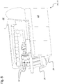
- FIGS. 1 and 2 each show perspective views of a first embodiment of a Verteilaggregates 10 according to the invention, which is provided for as uniform as possible, ideally for isolated delivery of granular material, in particular of seeds 12, fertilizer, etc.
- the distribution unit 10 may thus in the embodiment shown, a sowing unit 11 a distributor or sowing machine (not shown), in which normally a plurality of such sowing units 11 are arranged side by side for multi-row sowing.
- the distribution unit 10 or sowing unit 11 comprises an elongated housing 14 with a cylindrical inner surface 16 and an opening into the housing 14 inlet opening 18 for an air flow 20 with transported from this and transported into the housing 14 granular material or grains 12.
- the inlet opening 18 is Part of a connecting piece 22, which sits outside of the housing 14 and opens tangentially into this.
- a conveyor 24 mounted there, which can rotate concentrically there and the transport of the carried in the air flow 20 granular material or transported by this seed 12 is used.
- the air flow 20 and the rotating conveyor 24 promote the seeds 12 to an outlet opening 26 which connects approximately tangentially to the inner circumferential surface 16, as for example.
- the Fig. 4 ff clarify.
- the conveying device 24 has two paddle-like conveying elements 28 which strike along the inner lateral surface 16 and which are fastened opposite to a shaft 30 rotating concentrically in the housing 14.
- FIGS. 4 to 6 can recognize the paddle-like conveying elements 28 of the conveyor 24 for distribution and equalization of the crop flow of grains 12, although in the vicinity of the inlet opening 18 to first Can agglomerate 13 ( Fig. 5 . Fig. 6
- these are ideally lined up by the rotating movement of the conveying elements 28 in a manner such that the grains 12 are discharged through the outlet opening 26 individually and at constant intervals and in a constant dispensing direction ( Fig. 4 ), whereby the object of the present invention - the equalization of a good flow for the occasional delivery of grains - can be fulfilled as far as possible.
- Fig. 8 also discloses another option of the present invention.
- the inner circumferential surface 16 of the housing 14 may have a structuring 32 in the form of a continuous spiral, as in Fig. 3 and in Fig. 8 is recognizable.
- the spiral-shaped structuring 32 extends from a first end face 34, on which the connecting piece 22 is arranged, to the opposite end face 36, on which the outlet opening 26 is located.
- the spiral-like structure 32 is directed in the direction of rotation 38 of the conveyor 24 in the direction of the outlet opening 26 and opens there.
- the spiral-like structure 32 begins in the direction of rotation 38 of the conveyor 24 (see. Fig.
- the aforementioned spiral-like structure 32 may optionally have different pitch sections and be divided into a deceleration and separation winding.
- the delay thread provided with a smaller thread pitch is located near the inlet 18 and at the first end face 34, while the adjoining separating thread has a greater pitch in the direction of the outlet 26 and the second end face 36, so that the individual threads have approximately one width that corresponds to the diameter of the grains 12, so that they are guided in the threads.
- FIGS. 9 to 13 let recognize how the uniformly rotating paddle-like conveying elements 28 of the conveyor 24 in connection with the running through the housing 14 uniform air flow 20 and possibly the (optional) spiral structure 32 of the inner circumferential surface 16 of the housing 14 a homogenization of the flow of material 40 (at Grains, seeds 12, etc.), which in the ideal case leads to an equidistant discharge at the outlet 26.
- the sowing unit according to the invention provides a uniform grain separation of high quality, if not too many grains 12 are transported in the air flow 20 and an excessively high speed applied to the rotating shaft 30.
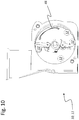
- the presentation of the Fig. 10 shows the promotion of the grains 12 in the vicinity of the inlet opening 18, which is still partially disordered and has not yet led to an optimal distribution of all grains on the respective conveyor elements 28.
- Some of the grains 12 are still uncontrollably swirled around in the housing 14, wherein they are normally all on the inner circumferential surface 16 due to the centrifugal forces acting after passing through the inlet opening 18 and there perform a circular or spiral movement 48 in the direction of rotation 38 of the shaft 30.
- After multiple circular movements 48 and approaching the outlet opening 26 are normally no more grains 12 in the housing 14, which are not moved by the conveying elements 28 and abut there ( Fig. 12 ), so that they are discharged in an ideal tangential movement 50 as a separate material flow 40 through the outlet opening 26 down from the housing 14 ( Fig. 12 . Fig. 13 . Fig. 14 ).
- the individual arrangement of the grains 12 on the conveying elements 28 in the vicinity of the outlet opening 26 normally ensures that only one grain 12 at each passing of the end section of each conveying element 28 pointing in the direction of the second end face 36 onto a ramp 52 leading tangentially away from the inner circumferential surface 16 is derived to the outlet 26 ( Fig. 13 ).
- This ramp 52 can optionally be in Fig. 13 have shown contour and provide for a tangential grain movement 50 through the outlet opening 26.
- the ramp 52 can, however, in principle also be shaped differently and, for example, the in Fig. 14 shown curved profile 54 which deflects the grains 12 after the tangential detachment movement 50 in an axial movement 56 which is parallel to the longitudinal direction of the housing 14 extends.
- the design of the paddle-like conveying elements 28 ensures a sufficient free cross-section in the housing interior between the inlet port 18 and the Outlet opening 26, so that possibly a portion of the conveyed grains 12 past the conveying elements 28 between the central shaft 30 and the space between the shaft 30 and the conveying elements 28 arranged thereon be guided and leave the housing 14 through the outlet 26.
- the longitudinal sides 42 of the paddle-like conveying elements 28 extend parallel to the longitudinal direction of the housing 14 and the shaft 30 and have a width extending over several tracks or grooves of the spiral structure 32 extends. As the FIGS. 1 to 14 can be seen, the radially extending in the housing 14 narrow sides 44 of the conveying elements 28 are significantly shorter than the longitudinal sides 42 and measure less than one third of the inner diameter of the housing 14 in the illustrated embodiment.
- FIGS. 15 to 17 show a further embodiment of the Verteilaggregats 10 and the sowing unit 11, in which the conveying elements 28 of the rotating conveyor 24 have a slightly helical course in the direction parallel to the shaft 30, whereby the axial feed of the grains is given in the direction of the housing outlet 26.
- the surfaces of the paddle-like conveying elements 28 are curved in the direction of their longitudinal sides 42 in such a way that a helical contour results, in which an acute angle between the longitudinal extension direction of the housing and the surface of the conveying elements 28 is formed. This curved contour is particularly good in Fig. 17 recognizable.
- the thread-like structuring of the inner circumferential surface 16 can be dispensed with, since the helical contour of the conveying elements 28 ensures the axial grain feed.
- the slight axial feed can also be done by the air flow, and or the constant feeding of grains and the resulting slight self-displacement.
- combinations of helical conveying elements and thread-like structuring of different shape and depth are possible and useful.
- FIGS. 18a and 18b show various alternative embodiments of the conveying elements 28, which can be designed and dimensioned differently depending on the material to be separated. So that can be done in Fig. 18a
- the conveying element 28a shown on the left can be used particularly well for grain singulation in wheat, while, for example, the conveying element 28b depicted next to it can be used for oilseed rape.
- the further variants 28c, 28d and 28e may be suitable, for example, for soya or similarly shaped grains.
- variants of the conveying elements 28 are each provided with counterweights 58, so that, if necessary, can be dispensed with spring elements in the region of the pivotal mounting of the conveying elements 28 on the shaft 30.
- the molded counterweights 58 may rather provide for the radial alignment of the conveyor elements 28 with rapid rotation of the shaft 30, while they can easily avoid dips or resistance occurring.
- the conveying element 28f may be used for wheat, while the variant 28h may be suitable for rapeseed, for example.
- the variant 28i shows a helical course, as he already in the FIGS. 15 to 17 is shown.
- the rotating conveyor 24 may have two oppositely disposed conveying elements 28 which are anchored to the shaft 30 via a suitable attachment.
- the rotating conveyor 24 may have two oppositely disposed conveying elements 28 which are anchored to the shaft 30 via a suitable attachment.
- the conveying element 28 rotates ( Fig. 20 ) or in which three, four or more similar or differently shaped paddle-like conveying elements 28 are provided, which are each arranged uniformly spaced from each other on the central shaft 30.
- the Fig. 19 shows, for example, a variant with four at an angle of each 90 ° to each other standing conveying elements 28, which are arranged uniformly distributed on the shaft 30.
- the corresponding Fig. 18b can be configured, for example, can be used for the separation of rapeseed.
- the conveying element 28 shown there can also interact with semicircular disks 60 and 62, which prevent a direct flow through the small rapeseed grains in the housing 14. The very small rapeseed grains are thus delayed at the discs 60 and 62 designed as baffle plates and prevented from pushing uncontrollably to the exit 26.
- one of the semicircular and rotating with the shaft 30 discs 60 between the axially opening into the first end face 34 of the housing 14 inlet opening 18 and spaced from the end face 34 rotating conveyor element 28 may be arranged, while a second disc 62 in the vicinity of in the second end face 36 located outlet opening 26 may be arranged. While the first disc 60 covers a circle segment of about 180 ° in the embodiment shown, the second disc 62 can cover a circular segment of, for example, 270 °, so that the rapeseed grains contained in the housing 14 are effectively prevented from reaching the outlet prematurely, before they are delivered there in isolated form.
- the paddle-like conveying elements 28 can each be suspended resiliently on the central shaft 30, so that they can escape with increased resistance.
- the FIGS. 4 to 12 . Fig. 16 . 17 and 19 let corresponding pivot mechanisms 46 recognize that preferably allow a pivoting movement of the conveying elements 28 by a defined pivoting angle as soon as they are blocked by too many grains, by foreign matter such as stones, wood o. The like. This will prevent damage.
- the resilient suspension on the shaft 30 and counterweights 58 can provide for the alignment of the conveying elements 28 and for their evasive movements.
- each conveying element 28 may have a contouring, for example a kink or a concave curvature (cf. FIGS. 15-17 ). Such contouring can have a beneficial effect on the grain promotion.
- the paddle-like conveying elements 28 in the interest of a high distribution and separation quality should extend in width across a portion of the outlet opening 26, so that they are swept by the conveyor elements 28 with rotating conveyor 24 and the Verteilgut is ejected almost tangentially.
- the central shaft 30 of the conveyor 24 may, for example, be driven by an electric motor.
- the central shaft 30 of the conveyor 24 or the rotatable conveying elements 28 may also be driven via the air flow 20 conducted into the housing 14 through the inlet opening 18.
- FIGS. 22 to 25 show a further alternative embodiment of the Verteilaggregats 10, which is dispensed with a central shaft.
- the grains 12 are conveyed by a rotating housing portion 70 with transverse web 68 and a fixed turn 66 through the housing 14 in the axial direction to the grain exit or to the outlet opening 26.
- the windings 66 are fixedly connected to the stationary housing part 72 and / or to the stationary grain exit 26.
- the grains 12 are urged by the rotational centrifugal forces to the outside to the inner circumferential surface 16 of the rotating housing portion 66.
- the rotating crossbar 68 provides for advancing movement of the grains 12 in the direction of rotation along the circumference of the housing, while the stationary windings 66 of the non-rotating scroll 64 provide axial advancement in the direction from the inlet 18 to the outlet 26.
- the spacing of the spiral turns 66 from the inner circumferential surface 16 of the rotating housing section 70 must be at least slightly smaller than the smallest grain diameter, while the pitch of the turns 66 may be configured as needed. The pitch can be based on the grain size, the desired feed in connection with the rotational speed of the crosspiece 68 and other sheparameter.
Description
Die vorliegende Erfindung betrifft ein Verteilaggregat für körniges Gut wie Samenkörner, Dünger o. dgl. Sie betrifft insbesondere ein Säaggregat mit den Merkmalen des unabhängigen Anspruchs 1.The present invention relates to a distribution unit for granular material such as seeds, fertilizer o. The like. It relates in particular to a sowing unit with the features of independent claim 1.
Verteilvorrichtungen für körniges Gut wie insbesondere Sämaschinen sind in zahlreichen Ausführungsvarianten bekannt. Herkömmlicherweise erfolgt die Kornförderung mit Hilfe eines Luftstromes, dem die Körner zudosiert werden. Anschließend wird der als Trägermedium dienende Luftstrom einem Verteiler zugeführt, der in eine Mehrzahl von Schlauchleitungen münden kann, die schließlich in nebeneinander angeordneten Scharen der Sämaschine enden können. Die Dosierung der Körner ermöglicht die Variation des Volumenstroms an ausgebrachten Körnern. Weitere Möglichkeiten, auf die Dosierung der Körner in den einzelnen Leitungen, die zu den Scharen führen, Einfluss zu nehmen, bestehen in der Regel nicht. Die Körner können zwar dem Luftstrom regelmäßig zugeführt werden. Allerdings wird die Stetigkeit der Kornzuführung während des luftunterstützten Transports mehr oder weniger beeinträchtigt, so dass die Kornablage an den Säscharen oftmals ungleichmäßig erfolgt, was zu Nachteilen bei der Standraumzuteilung der einzelnen Pflanzen führen kann.Distribution devices for granular material, in particular seed drills, are known in numerous design variants. Conventionally, the grain is conveyed by means of an air flow to which the grains are metered. Subsequently, the serving as a carrier medium air flow is supplied to a manifold that can open into a plurality of hose lines, which can eventually end in juxtaposed crowds of seeder. The dosage of the grains allows the variation of the volume flow of applied grains. Other ways to influence the dosage of the grains in the individual lines that lead to the droves, usually do not exist. The grains can be fed regularly to the air flow. However, the consistency of the grain feed during air-assisted transport is more or less affected, so that the grain deposition on the coulters often uneven, which can lead to disadvantages in the stand allocation of individual plants.
Eine Einrichtung zur Verstetigung eines Gutstromes einer Drill- bzw. Sämaschine ist aus der
Eine für unterschiedliche Korngrößen und Samenarten universell einsetzbare Vorrichtung zum Vereinzeln und Abgeben von körnigem Gut, insbesondere eine Einzelkornsävorrichtung ist weiterhin in der
Die
Eine weitere Einzelkorndosiervorrichtung zur Einzelkornaussaat von Getreide ist aus der
Auch die
Bei den bekannten Dosiereinrichtungen handelt es sich entweder um modifizierte Einzelkornsäaggregate, die zwar eine präzise Kornvereinzelung erlauben, die aber gegenüber volumetrisch dosierenden Drillmaschinen in ihrer Verarbeitungskapazität und in ihrem Kornvolumenstrom begrenzt sind und/oder in ihrem Aufbau und ihrer Funktion aufwändig und störanfällig sind. Die bekannt gewordenen Zusatzgeräte, welche die regelmäßige Abgabe der Saatkörner bei volumetrisch dosierenden Maschinen verbessern sollen, reichen hingegen nicht an die Vereinzelungsqualität herkömmlicher Einzelkornsäaggregate heran.The known metering devices are either modified Einzelkornsäaggregate, although allow precise grain separation, but limited in their processing capacity and in their grain volume flow over volumetric metering seed drills and / or are complex and prone to failure in their structure and function. The known accessories, which are intended to improve the regular delivery of seeds in volumetric metering machines, however, do not reach the singulation quality of conventional Einzelkornsäaggregate zoom.
Ein vorrangiges Ziel der Erfindung besteht darin, die Abgabegenauigkeit und/oder die Kornabstände bei einer volumetrischen Kornförderung soweit zu verbessern, dass sich damit die Korndosierung hinsichtlich ihrer Vereinzelungsqualität einer Einzelkorndosierung annähert oder diese im Idealfall erreicht, wobei gleichzeitig ein hoher Kornvolumenstrom ermöglicht sein soll. Diese Vorgaben sollen mit einem einfachen, robusten und für Störungen wenig anfälligen Aufbau und einer einfachen Funktion, wie er/sie für volumetrisch dosierende Drillmaschinen charakteristisch ist/sind, erreicht werden.A primary object of the invention is to improve the delivery accuracy and / or the grain distances in a volumetric grain promotion so far that it approaches the Korndosierung in terms of their singling quality of a single-grain metering or ideally achieved this, while a high grain volume flow should be possible. These specifications are intended to be achieved with a simple, robust and interference-prone design, and a simple function characteristic of volumetric metering seed drills.
Das Ziel der Erfindung wird mit dem Gegenstand des unabhängigen Anspruchs erreicht. Merkmale vorteilhafter Weiterbildungen der Erfindung ergeben sich aus den abhängigen Ansprüchen. Zur Erreichung des genannten Ziels schlägt die Erfindung ein Verteilaggregat für körniges Gut wie Samenkörner, Dünger o. dgl. mit den nachfolgend erläuterten Merkmalen vor, das insbesondere als Säaggregat einer Verteil- oder Sämaschine eingesetzt werden kann. Das erfindungsgemäße Verteilaggregat umfasst ein Gehäuse in einer zylindrischen Form mit wenigstens einer Einlassöffnung zur Aufnahme und für die Beförderung körnigen Gutes oder beförderter Samenkörner sowie einer Auslassöffnung zur Abgabe des körnigen Guts bzw. der Samenkörner in weitgehend regelmäßigen Abständen voneinander. Weiterhin umfasst das Aggregat eine im Gehäuse befindliche Fördereinrichtung mit wenigstens einem rotierenden, ungefähr axial und radial zur Innenseite des Gehäuses angeordneten bzw. verlaufenden Förderelement zur Erfassung, Handhabung, Förderung und/oder Aufreihung bzw. Gruppierung des körnigen Gutes bzw. der Samenkörner. Die Körner werden vorzugsweise mit einer gewissen Geschwindigkeit in das Gehäuse geleitet, so dass sie nach dem Passieren der Einlassöffnung mit Hilfe der dabei entstehenden Fliehkräfte sowie der inneren Gehäusegestaltung gelenkt, geleitet und in regelmäßige Anordnung gebracht werden können. So werden die Körner mit Hilfe der geschwindigkeitsbedingten Fliehkräfte an einem Innenmantelbereich des Gehäuses gehalten und können sich dort drängen und gegeneinander ausrichten und in einer Linie ordnen bzw. in einem Winkel aufreihen, der einer Winkelstellung zwischen der Mantelfläche und dem radialen Förderelement entspricht. Das Ziel dieser Ausrichtung besteht darin, am Ende dieser Aufreihung jeweils nur ein einzelnes Korn durch die Auslassöffnung zu entlassen, wobei die jeweils folgenden Körner immer in weitgehend konstanten Zeitabständen und/oder Kornabständen freigegeben und vom Gehäuse abgegeben werden. Die Anordnung und Gruppierung der schnell durch das Gehäuse geförderten Körner führt weiterhin dazu, dass diese in einer vordefinierten Bahn an der Mantelfläche der Gehäuseinnenseite entlang geführt und am Ende des Vereinzelungsprozesses die Auslassöffnung annähernd tangential verlassen.The object of the invention is achieved with the subject matter of the independent claim. Features of advantageous developments of the invention will become apparent from the dependent claims. To achieve the above object, the invention proposes a distribution unit for granular material such as seeds, fertilizer o. The like. With the features explained below, which can be used in particular as a sowing unit of a distribution or seed drill. The distribution unit according to the invention comprises a housing in a cylindrical shape with at least one inlet opening for receiving and for transporting granular material or transported seeds and an outlet opening for discharging the granular Guts or the seeds at substantially regular intervals from each other. Furthermore, the unit comprises a conveyor located in the housing with at least one rotating, approximately axially and radially arranged to the inside of the housing or extending conveyor element for detecting, handling, promotion and / or alignment or grouping of the granular material or the seeds. The grains are preferably directed at a certain speed into the housing so that they can be steered, passed and placed in regular arrangement after passing through the inlet opening with the aid of the resulting centrifugal forces and the inner housing design. So the grains are using the speed-related centrifugal forces on an inner shell region of the housing held and can crowd there and align against each other and in a line arrange or line up at an angle corresponding to an angular position between the lateral surface and the radial conveying element. The goal of this alignment is to discharge at the end of this array only a single grain through the outlet opening, wherein the respective following grains are always released at largely constant intervals and / or grain intervals and discharged from the housing. The arrangement and grouping of the grains rapidly conveyed through the housing furthermore leads to them being guided in a predefined path along the lateral surface of the inner side of the housing and leaving the outlet opening approximately tangentially at the end of the singulation process.
Bei dem erfindungsgemäßen Verteilaggregat ist es weiterhin von Vorteil, wenn sich die vom Förderelement transportierten oder mitgenommenen Körner im Gehäuse nicht in einer zu dichten Packung zusammenballen, sondern mindestens einen einseitigen Freiraum haben oder bilden, um dadurch überschüssige Körner abdrängen zu können, damit sich am Förderelement eine annähernd lineare Kornausrichtung ausbilden kann. Mit linearer Kornausrichtung kann in diesem Zusammenhang insbesondere eine Kornausrichtung parallel zur Oberfläche des Förderelements bzw. parallel zur Längserstreckungsrichtung des Gehäuses gemeint sein. Die Aufreihung am Förderelement bzw. im Innenmantelbereich des Gehäuses erfährt. einen leichten gerichteten Vorschub in eine axiale Richtung, um die Position des jeweils gezielt abgeführten Kornes sicher zu besetzen und um keine Lücken zu lassen, die zu unregelmäßigen Kornabständen führen würden.In the Verteilaggregat invention, it is also advantageous if the transported or entrained by the conveying element grains in the housing do not agglomerate in a too dense package, but at least have a one-sided space or form to thereby be able to push away excess grains, so on the conveyor element can form an approximately linear grain orientation. In this context, linear grain orientation may, in particular, mean a grain orientation parallel to the surface of the conveyor element or parallel to the longitudinal extension direction of the housing. The arrangement on the conveyor element resp . experiences in the inner shell region of the housing. a slight directed feed in an axial direction to safely occupy the position of each targeted grain and to leave no gaps, which would lead to irregular grain intervals.
Das Gehäuse kann insbesondere eine zylindrische, wahlweise auch eine einseitig konisch zulaufende Innenmantelfläche aufweisen. Darüber hinaus sind auch andere Gehäusekonturen denkbar, bspw. eine sich elliptisch oder mit anderer Kontur verjüngende oder erweiternde Gehäuseinnenseite. Die Innenmantelfläche des Gehäuses sollte hingegen keine ausgeprägten Stufen oder Kanten aufweisen, die dem Korntransport bzw. dem Kornfluss erhöhten Widerstand entgegensetzen könnten.The housing may in particular have a cylindrical, optionally also a unilaterally tapered inner circumferential surface. In addition, other housing contours are conceivable, for example. An elliptical or with other contour tapering or widening inside the housing. The inner surface of the housing, however, should have no pronounced steps or edges, which could oppose the grain transport or the grain flow increased resistance.
Eine bevorzugte Ausführungsvariante des erfindungsgemäßen Verteilaggregats ist mit einer durch die Einlassöffnung geführten Luftströmung beaufschlagt, die gleichzeitig das körnige Gut oder die Samenkörner fördert und das Gehäuse auch wieder durch die Auslassöffnung verlässt. Diese Luftströmung dient gleichzeitig dazu, die Körner im Gehäuse in Bewegung zu halten und auf ihrer vorgesehenen Bahn zu lenken und zu befördern. Die Körner können aus einem zentralen Behälter durch den Einlass herangeführt werden. Wahlweise können für die Körner auch kleinere Zwischenbehälter vorgesehen sein, die jedem Verteil- oder Vereinzelungsaggregat zugeordnet sind. Dort kann ggf. auch die Zudosierung der Körner zum tragenden Luftstrom erfolgen. Der Luftstrom, mit dem die Körner herangeführt werden, führt anschließend durch den Dosierer bzw. das Aggregat und trägt die abgegebenen Körner in der oder nach der Abgabe weiter. Der Luftstrom kann in vorteilhafter Weise dafür sorgen, dass die Körner auch bei einem Stillstand des Förderelementes mit dem tragenden Luftstrom weiterhin den Dosierer durchströmen können.A preferred embodiment of the distribution unit according to the invention is acted upon by an air flow guided through the inlet opening, which at the same time conveys the granular material or the seeds and also leaves the housing again through the outlet opening. This air flow also serves to keep the grains in the housing in motion and to steer and convey on their intended path. The grains can be fed from a central container through the inlet. Optionally, smaller intermediate containers can be provided for the grains, which are assigned to each distribution or separation unit. There If necessary, the metered addition of the grains to the carrying air stream can also take place. The air flow, with which the grains are brought, then passes through the doser or the aggregate and carries the delivered grains in or after delivery on. The air flow can advantageously ensure that the grains can continue to flow through the meter even when the conveyor element is at a standstill with the carrying air flow.
Anstelle der Verwendung eines tragenden Luftstroms kann die Kornförderung auch rein mechanisch erfolgen, insbesondere durch die Rotationsbewegung des Förderelements, das die Körner innerhalb des Gehäuses in eine kreis- oder spiralförmige Bewegung zwingt und dadurch für die gewünschte Vereinzelung sorgt, wenn die Körner durch die Auslassöffnung abgegeben werden. Hierbei kann das rotierende Förderelement insbesondere einen elektromotorischen Antrieb aufweisen, der je nach Bedarf eine Anpassung der Umdrehungsgeschwindigkeit ermöglicht.Instead of using a carrying air stream, the grain conveying may also be purely mechanical, in particular by the rotational movement of the conveying element, which forces the grains within the housing in a circular or spiral movement and thereby provides the desired separation when the grains discharged through the outlet opening become. Here, the rotating conveyor element may in particular have an electric motor drive, which allows an adjustment of the rotational speed as needed.
Jedes geförderte Korn durchläuft vor der Kornabgabe durch den Auslass eine Kreisbewegung bzw. eine spiralförmige Bewegungsbahn, die einen Winkel von mindestens 360 Grad abdeckt, wobei es von dem wenigstens einen Förderelement auf einer annähernd zylindrischen bzw. konisch gestalteten Mantelfläche gehalten wird und gleichzeitig einen leichten axialen Vorschub in Richtung zur Kornabgabe am Auslass erfährt. In diesem Zusammenhang ist es sinnvoll, wenn der Vorschub der Körner zumindest im Bereich der Auslassöffnung für das letzte Korn - d.h. für das gerade abgegebene Korn - durch eine führende Kontur vorgegeben ist.Each conveyed grain passes through the outlet before the grain discharge a circular motion or a spiral path of movement which covers an angle of at least 360 degrees, being held by the at least one conveying element on an approximately cylindrical or conically shaped lateral surface and at the same time a slight axial Feed in the direction of the grain output at the outlet learns. In this context, it makes sense if the feeding of the grains at least in the region of the outlet opening for the last grain -. for the just released grain - is given by a leading contour.
Als besonders vorteilhaft hat sich ein weiteres Ausstattungsmerkmal des erfindungsgemäßen Verteilaggregats erwiesen, bei dem die Innenmantelfläche des Gehäuses eine Strukturierung in Gestalt einer durchgängigen Spirale oder Führungsbahn aufweist, die von einer Stirnseite zur gegenüber liegenden Stirnseite oder einen Teilabschnitt davon reicht. Wahlweise kann diese spiralartige Strukturierung eine durchgängige konstante Steigung oder auch Abschnitte jeweils unterschiedlicher Steigungen aufweisen, wobei die Steigung zur Auslassöffnung hin vorzugsweise größer ist als im Bereich der Einlassöffnung. Wenn die Steigung in Richtung zur bzw. in zunehmender Nähe zur Auslassöffnung größer wird, so kann die dadurch gebildete Rillenbreite, die sich aus dieser Strukturierung ergibt, sinnvollerweise auf die Korngröße abgestimmt sein, so dass die Körner durch die mit der Strukturierung gebildeten spiralförmigen Rillen gleichsam gelenkt und geführt werden, bis sie einzeln nacheinander die Auslassöffnung passieren. Im vorderen Bereich, näher zum Einlass hin, kann die Strukturierung ggf. auch enger sein bzw. eine geringere Steigung aufweisen, da sich dort in aller Regel die Körner ohnehin stärker zusammenballen und einen Art Puffer bilden, so dass eine direkte Lenkung jedes einzelnen Kornes auf der durch die Strukturierung gebildeten Führungsbahn noch nicht gleichermaßen erforderlich ist wie in Richtung zum Kornauslass hin.Particularly advantageous is another feature of the invention Verteilaggregats has proven, in which the inner circumferential surface of the housing has a structuring in the form of a continuous spiral or track, which extends from one end face to the opposite end side or a portion thereof. Optionally, this spiral-like structuring may have a continuous constant pitch or also sections of respectively different pitches, wherein the pitch towards the outlet opening is preferably greater than in the area of the inlet opening. As the pitch increases toward or in increasing proximity to the outlet opening, the groove width formed thereby resulting from this patterning may usefully be tuned to the grain size so that the grains through the helical grooves formed with the patterning, as it were be steered and guided until they pass one by one the outlet opening. In the front area, closer to the inlet, the structuring may also be narrower or have a smaller pitch, since there As a rule, the grains aggregate more strongly anyway and form a kind of buffer, so that a direct steering of each individual grain on the guideway formed by the structuring is not equally required as in the direction of the grain outlet.
Als sinnvolle Größenordnungen für die Steigungen haben sich bspw. Maße von ca. 6 bis 7 mm je Windung am Ausgang und ca. 3 bis 3,5 mm je Windung am Eingang für die Aussaat von Weizensamen erwiesen. Je nach Korngröße sind auch andere Steigungsmaße möglich und sinnvoll.For example, dimensions of about 6 to 7 mm per turn at the exit and about 3 to 3.5 mm per turn at the entrance for the sowing of wheat seeds have proven to be sensible orders of magnitude for the gradients. Depending on the grain size, other pitch dimensions are possible and useful.
Als besonderer vorteilhaft hat sich die Reinigungswirkung der Strukturierung herausgestellt, da sie das Anhaften und Verbleiben von Verunreinigungen und Fremdstoffen effektiv unterbinden kann. Während solche Fremdstoffe wie bspw. Grashalme an einer glatten, unstrukturierten Wand nur schwer mitgenommen werden, sorgt die Strukturierung im Zusammenhang mit der ständigen Kornbewegung für die Mitnahme aller solcher Verunreinigungen und Fremdstoffe, so dass sie ohne weitere Störungen aus dem Gehäuse ausgetragen werden.As a particular advantage, the cleaning effect of the structuring has been found because it can effectively prevent the adhesion and retention of impurities and foreign substances. While such foreign matter as, for example, grass blades on a smooth, unstructured wall are difficult to take along, the structuring in connection with the constant grain movement ensures the entrainment of all such impurities and foreign matter, so that they are discharged from the housing without further disturbances.
Ein charakteristisches Merkmal des Verteilaggregats besteht darin, dass nahezu alle Körner im Dosierer in Bewegung sind, wobei diese Bewegung durch das Förderelement und/oder den Luftstrom bewirkt ist. Der Dosierer ist durch seine besondere Art der Kornförderung problemlos in der Lage, kurze Schwankungen oder Unregelmäßigkeiten im Kornzustrom auszugleichen und damit eine Pufferfunktion zu erfüllen, wenn der Kornvolumenstrom in der Zuführung schwanken sollte oder plötzlich abnimmt.A characteristic feature of the distributor is that almost all the grains in the dispenser are in motion, this movement being effected by the conveyor and / or the air flow. Due to its special type of grain conveying, the dosing device is able to easily compensate for short fluctuations or irregularities in the grain inflow and thus to fulfill a buffer function if the grain volume flow in the feeder fluctuates or suddenly decreases.
Die bspw. als gleichmäßig rotierende paddelartige Förderelemente ausgebildete Fördereinrichtung im Gehäuse ermöglicht im Zusammenhang mit der gleichmäßigen Luftströmung und der spiralförmigen Strukturierung der Innenmantelfläche des Gehäuses eine Vergleichmäßigung des Gutstroms (an Körnern, Saatkörnern etc.), die zu einer äquidistanten Abgabe am Auslass führt, was wiederum mit der gleichmäßigen und präzise einzuhaltenden Abgabegeschwindigkeit und Abgaberichtung für eine sehr gleichmäßige Kornvereinzelung sorgen kann.The example. As a uniformly rotating paddle-like conveying elements formed conveyor in the housing allows in connection with the uniform air flow and the spiral patterning of the inner circumferential surface of the housing equalization of the crop (on grains, seeds, etc.), which leads to an equidistant discharge at the outlet, which In turn, with the uniform and precise to be observed dispensing speed and dispensing direction can ensure a very uniform grain separation.
Eine konkrete Ausgestaltung des erfindungsgemäßen Verteilaggregats für körniges Gut wie Samenkörner, Dünger o. dgl., das insbesondere ein Säaggregat einer Verteil- oder Sämaschine sein kann, weist ein Gehäuse mit zylindrischer Innenmantelfläche und wenigstens einer darin mündenden Einlassöffnung für eine Luftströmung und darin befördertem körnigen Gut auf. Im Gehäuse rotiert konzentrisch eine Fördereinrichtung für das in der Luftströmung getragene körnige Gut und fördert dies zur wenigstens einen Auslassöffnung, die annähernd tangential an die Innenmantelfläche anschließt. Die Fördereinrichtung weist wenigstens ein an der Innenmantelfläche entlang streichendes paddelartiges Förderelement auf. Zudem weist die Innenmantelfläche des Gehäuses eine Strukturierung in Gestalt einer durchgängigen Spirale auf, die von einer Stirnseite zur gegenüber liegenden Stirnseite reicht. Die spiralartige Strukturierung ist in Umdrehungsrichtung der Fördereinrichtung in Richtung zur Auslassöffnung gerichtet und mündet dort. Die spiralartige Strukturierung beginnt in Umdrehungsrichtung der Fördereinrichtung im Bereich der Einlassöffnung und verbindet auf diese Weise die Einlass- mit der Auslassöffnung, so dass die vom Luftstrom getragenen Körner die Einlassöffnung passieren, von der Fördereinrichtung in Verbindung mit der spiralartigen Strukturierung der Wände geordnet und vergleichmäßigt werden und schließlich die Auslassöffnung als weitgehend gleichmäßigen Gutstrom an Körnern verlassen.A concrete embodiment of the granular material distribution unit according to the invention such as seeds, fertilizer o. The like., Which may be in particular a sowing unit of a distributor or seeder, has a housing with a cylindrical inner surface and at least one opening therein opening for an air flow and granular material conveyed therein on. The housing rotates concentrically a conveyor for the carried in the air flow granular material and promotes this to at least one outlet opening, which connects approximately tangentially to the inner circumferential surface. The conveying device has at least one paddle-like conveying element which strikes along the inner lateral surface. In addition, the inner circumferential surface of the housing has a structuring in the form of a continuous spiral, which extends from one end face to the opposite end face. The spiral-like structuring is directed in the direction of rotation of the conveyor in the direction of the outlet opening and opens there. The spiral-like structuring begins in the direction of rotation of the conveyor in the region of the inlet opening and thus connects the inlet and the outlet opening, so that the grains carried by the air flow pass through the inlet opening, ordered by the conveyor in conjunction with the spiral-like structuring of the walls and made uniform and finally leave the outlet as a largely uniform crop flow of grains.
Eine weitere Variante des erfindungsgemäßen Verteilaggregats sieht vor, dass eine Längsseite des wenigstens einen paddelartigen Förderelementes sich parallel zur Längserstreckungsrichtung des Gehäuses erstreckt, wobei eine Schmalseite des Förderelementes normalerweise kürzer ist als die Längsseite und bspw. weniger als die Hälfte des Innendurchmessers des Gehäuses misst. Wahlweise kann die rotierende Fördereinrichtung zwei, drei, vier oder mehr gleichartig oder unterschiedlich geformte paddelartige Förderelemente aufweisen, die jeweils gleichmäßig voneinander beabstandet an einer zentralen Welle angeordnet sind. Um Blockaden zu vermeiden, können die paddelartigen Förderelemente jeweils nachgiebig (ggf. auch federnd) an der zentralen Welle aufgehängt sein, so dass sie bei erhöhtem Widerstand ausweichen können.A further variant of the distribution unit according to the invention provides that a longitudinal side of the at least one paddle-like conveying element extends parallel to the longitudinal direction of the housing, wherein a narrow side of the conveying element is usually shorter than the longitudinal side and, for example. Measures less than half of the inner diameter of the housing. Optionally, the rotary conveyor may comprise two, three, four or more similar or differently shaped paddle-like conveying elements, each equally spaced from each other on a central shaft. In order to avoid blockages, the paddle-like conveying elements can each be resiliently suspended (if necessary also resiliently) on the central shaft, so that they can escape with increased resistance.
Die Kornförderung kann ggf. dadurch verbessert werden, dass das wenigstens eine paddelartige Förderelement in Umdrehungsrichtung eine konkave Wölbung aufweist. Zudem ist es sinnvoll, wenn das wenigstens eine paddelartige Förderelement einen geringen Abstand zur Innenmantelfläche des Gehäuses aufweist, der kleiner ist als die Hälfte des kleinsten Korndurchmessers des auszubringenden Verteilgutes. Der Abstand der Förderelemente oder Förderpaddel zur Wand sollte ein Mindestmaß nicht unterschreiten, um Klemmerscheinungen zu verhindern, insbesondere bei in das Gehäuse geratenen Fremdstoffen oder Verunreinigungen. Der Abstand sollte allerdings auch nicht zu groß sein, damit keinesfalls Körner zwischen die Gehäusewand und die äußere Umfangskante der Förderelemente oder -paddel geraten und dort eingeklemmt werden können, was zu Störungen im Korntransport und zu Stauungen führen könnte. Ein Abstand von ca. 0,2 bis 0,5 mm zur Wand, insbesondere von ca. 0,3 mm, hat sich in der Praxis als tauglich erwiesen.The grain conveying may possibly be improved by the fact that the at least one paddle-like conveying element has a concave curvature in the direction of rotation. In addition, it is useful if the at least one paddle-like conveying element has a small distance to the inner circumferential surface of the housing, which is smaller than half of the smallest grain diameter of the spreading material to be delivered. The distance of the conveyor elements or conveyor paddle to the wall should not be less than a minimum to prevent Klemmerscheinungen, especially in the case of foreign matter or impurities in the housing. However, the distance should not be too large, so that no grains between the housing wall and the outer peripheral edge of the conveying elements or paddles advised and can be trapped there, which could lead to disturbances in grain transport and congestion. One Distance of about 0.2 to 0.5 mm to the wall, in particular of about 0.3 mm, has proven to be suitable in practice.
Außerdem sollte das wenigstens eine paddelartige Förderelement im Interesse einer hohen Verteil- und Vereinzelungsqualität in seiner Breite über einen Teil der Auslassöffnung reichen, so dass diese bei rotierender Fördereinrichtung überstrichen wird. Durch Einströmung einer gleichmäßigen, nicht pulsierenden Luftströmung mit ungefähr konstantem Volumenstrom an Luft und an mitgenommenen Körnern in das Gehäuseinnere mit der darin rotierenden Fördereinrichtung wird ein funktionierendes Einzelkornsäaggregat zur Verfügung gestellt, bei dem die Körner vereinzelt und in gleichmäßigen Abständen voneinander durch die Auslassöffnung abgegeben werden. Der erwähnte Volumenstrom an Luft kann wahlweise auch von der Fahrgeschwindigkeit der Zugmaschine abhängig gemacht werden. Zudem kann ein separater Antrieb des Förderelements ggf. entfallen, so dass dieses nur passiv vom Luftvolumenstrom in Rotation versetzt wird.In addition, the at least one paddle-like conveying element in the interest of a high distribution and separation quality should extend in its width over part of the outlet opening so that it is swept over by the rotating conveyor. By flowing a uniform, non-pulsating air flow with approximately constant volume flow of air and entrained grains into the housing interior with the conveyor rotating therein, a functioning Einzelkornsäaggregat is provided, in which the grains are separated and discharged at equal intervals from each other through the outlet. The mentioned volume flow of air can optionally be made dependent on the driving speed of the tractor. In addition, a separate drive of the conveyor element may be omitted, so that this is only passively offset by the air flow in rotation.
Die Umdrehungsgeschwindigkeit und die Anzahl der paddelartigen Förderelemente richtet sich sinnvollerweise nach dem jeweils geförderten und vereinzelten Saatgut. So hat sich bspw. für die Aussaat von Raps die Verwendung eines einzelnen Förderelements bzw. Förderpaddel als sinnvoll herausgestellt, das zudem relativ langsam rotieren sollte. Bei der Aussaat von Weizen haben sich jedoch zwei gegenüber liegend angeordnete Förderelemente bzw. Förderpaddel, die relativ schnell rotieren - bspw. mit einer Frequenz von ca. 25 bis 50 Hz - als sinnvolle Bauvariante herausgestellt. Bei zwei Förderelementen ergibt sich daraus eine Kornfrequenz bei der Abgabe von ca. 50 bis 100 Hz.The speed of rotation and the number of paddle-like conveying elements expediently depend on the respectively extracted and separated seed. Thus, for example, the use of a single conveying element or conveying paddle has proven to be useful for sowing rapeseed, which should also rotate relatively slowly. When sowing wheat, however, have two oppositely arranged conveying elements or Förderpaddel that rotate relatively quickly - eg. With a frequency of about 25 to 50 Hz - proven to be a useful construction variant. With two conveying elements, this results in a grain frequency in the delivery of about 50 to 100 Hz.
Eine zentrale Welle der Fördereinrichtung kann bspw. elektromotorisch angetrieben sein. Wahlweise können die paddelartigen Förderelemente bei einer einfachen Antriebsvariante der Fördereinrichtung auch über die durch die Einlassöffnung ins Gehäuse geleitete Luftströmung angetrieben sein. Die Paddel können für eine höhere Abgabegenauigkeit wahlweise elektromotorisch angetrieben sein, wobei im Interesse einer konstanten und äquidistanten Kornabgabe eine Modulierung der Antriebsdrehzahl nicht wünschenswert ist, sondern lediglich eine Anpassung an die Fahrgeschwindigkeit der zugehörigen Trägermaschine (z.B. der Sämaschine). Bei einem je nach gewünschter Ablagepräzision durchaus sinnvollen Verzicht auf einen motorischen Antrieb der Fördereinrichtung sorgt nur der Luftstrom, der durch die Einlassöffnung in das Gehäuse tritt und die Körner mitträgt, für den Antrieb der Fördereinrichtung bzw. der Förderelemente, was zwangsläufig mit einem Verlust der Ablagegenauigkeit verbunden ist. Allerdings kann dies je nach Anwendungsfall akzeptabel sein und zumindest teilweise durch den sehr einfachen und kostengünstigen Aufbau des Säaggregats, das in diesem Fall nur sehr wenige Teile umfasst, wettgemacht werden.A central shaft of the conveyor may, for example, be driven by an electric motor. Optionally, the paddle-like conveying elements can be driven in a simple drive variant of the conveyor via the air flow through the inlet opening into the housing. The paddles can be driven by an electric motor for a higher delivery accuracy, wherein in the interest of a constant and equidistant grain output modulation of the drive speed is not desirable, but only an adaptation to the driving speed of the associated carrier machine (eg the drill). In a depending on the desired filing precision quite meaningful abandonment of a motor drive the conveyor ensures only the air flow that enters through the inlet opening in the housing and carries the grains for driving the conveyor or the conveyor elements, which inevitably with a loss of storage accuracy connected is. However, this can be acceptable depending on the application and at least partially offset by the very simple and inexpensive construction of the sowing unit, which in this case comprises only a very few parts.
Die Erfindung umfasst neben dem Verteilaggregat auch eine mehrreihige Verteilmaschine für körniges Gut wie Samenkörner, Dünger o. dgl., insbesondere eine Verteil- oder Sämaschine, die mehrere nebeneinander angeordnete, gleichartige Verteilaggregate gemäß einer der zuvor beschriebenen Ausführungsvarianten aufweist.In addition to the distribution unit, the invention also includes a multi-row distribution machine for granular material such as seeds, fertilizer or the like, in particular a distribution or seed drill which has a plurality of juxtaposed distribution units according to one of the embodiments described above.
Es sei nochmals ergänzend an dieser Stelle erwähnt, dass die Innenmantelfläche, in der die Fördereinrichtung rotiert, nicht zwingend zylindrisch geformt sein muss, sondern auch einseitig konisch zulaufen kann. Die Förderelemente der rotierenden Fördereinrichtung können mit einer entsprechenden Schrägstellung so an eine solche konische Innenmantelfläche angepasst sein, dass ihr Abstand zur Wand gleichmäßig klein ist. Die spiralförmige Strukturierung der Innenmantelfläche kann ebenfalls an eine solche Formgebung angepasst sein oder je nach Ausführungsvariante auch fehlen kann, wobei die Steigung der Strukturierung über den sich konisch verjüngenden Innendurchmesser des Gehäuses konstant bleiben kann. Unabhängig von der Formgebung der Innenmantelfläche kann es sinnvoll sein, die Steigung oder Dimensionierung der Strukturierung an die typischerweise verwendeten Korngrößen und/oder an den Volumenstrom an geförderten Körnern anzupassen. Die Innenmantelfläche kann wahlweise auch zylindrisch sein und einen glatten, nicht strukturierten Innenmantel aufweisen, wobei eine Förderrichtung des Korngutes alleine durch den Luftstrom und/oder durch eine leichte Schrägstellung des Förderelementes (z.B. leichte Schneckenform) zu gewährleisten ist.It should be mentioned again at this point that the inner circumferential surface, in which the conveyor rotates, does not necessarily have to be cylindrically shaped, but can also taper on one side. The conveying elements of the rotating conveyor can be adapted with a corresponding inclination to such a conical inner surface, that their distance from the wall is uniformly small. The spiral-shaped structuring of the inner circumferential surface may also be adapted to such a shape or, depending on the embodiment, may also be missing, wherein the pitch of the structuring may remain constant over the conically tapering inner diameter of the housing. Irrespective of the shaping of the inner circumferential surface, it may be useful to adapt the pitch or dimensioning of the structuring to the grain sizes typically used and / or to the volume flow of conveyed grains. Optionally, the inner lateral surface can also be cylindrical and have a smooth, non-structured inner casing, wherein a conveying direction of the grain good is to be ensured solely by the air flow and / or by a slight inclination of the conveying element (for example a slight screw shape).
Im Folgenden werden nochmals die wichtigsten und einige ergänzende Aspekte der vorliegenden Erfindung wiederholt, wobei insbesondere die denkbaren Varianten der konkreten Gestaltung des erfindungsgemäßen Verteilaggragats mit ihren konstruktiven Details erläutert werden. Das mit der vorliegenden Erfindung definierte Verteilaggregat dient der möglichst gleichmäßigen und je nach Bedarf bzw. Konfiguration bzw. Betriebsmodus auch der vereinzelten Abgabe von körnigem Gut wie bspw. Samenkörnern, Dünger etc. Wenn somit im vorliegenden Zusammenhang von einem Verteilaggregat die Rede ist, so ist damit in aller Regel ein Säaggregat einer Verteil- oder Sämaschine gemeint. Bei einer solchen Sämaschine sind normalerweise mehrere gleichartige Säaggregate nebeneinander angeordnet, so dass eine mehrreihige Aussaat ermöglicht ist.In the following, the most important and some additional aspects of the present invention will be repeated, wherein in particular the conceivable variants of the specific design of the distributor agglutinate according to the invention will be explained with their design details. The distribution unit defined by the present invention serves as uniform as possible and as required or configuration or mode of operation also the isolated delivery of granular material such as seeds, fertilizer, etc. Thus, if in the present context of a distribution unit is mentioned, so thus usually meant a sowing unit of a distribution or seed drill. In such a sowing machine several similar sowing units are usually arranged side by side, so that a multi-row sowing is possible.
Alle von der Erfindung umfassten Bauvarianten des erfindungsgemäßen Verteilaggregats oder Säaggregats umfassen jeweils ein zylindrisches Gehäuse mit einer zylindrischen Innenmantelfläche und einer in das Gehäuse mündenden Einlassöffnung für eine Luftströmung mit von dieser transportiertem und in das Gehäuse befördertem körnigem Gut bzw. Samenkörner. Das zylindrische Gehäuse kann eine längliche Form aufweisen, so dass die Länge der Zylinderform größer ist als der Durchmesser des Gehäuses. Wahlweise jedoch kann das Gehäuse auch relativ kurz ausgeführt sein, so dass sein Durchmesser ggf. größer sein kann als seine Länge zwischen den Stirnseiten der Zylinderform. Unabhängig von der Länge des zylindrischen Gehäuses mündet die Einlassöffnung tangential an einer der beiden gegenüber liegenden Stirnseiten des durch das Gehäuse gebildeten Zylinders in das Gehäuse, so dass die Luftströmung ebenfalls tangential in das Gehäuseinnere eintreten kann. Normalerweise ist ein Anschlussstutzen o. dgl. vorgesehen, der die Einlassöffnung enthält und der außen am Gehäuse sitzt und tangential in dieses mündet. An der anderen Stirnseite des Gehäuses, welche der Stirnseite mit der Einlassöffnung gegenüber liegt, befindet sich eine Auslassöffnung des Verteil- oder Säaggregats, die wiederum tangential zur zylindrischen Innenmantelfläche des Gehäuses angeordnet ist, so dass die Einlassöffnung und die Auslass- oder Abgabeöffnung entweder parallel zueinander angeordnet sind oder dass zumindest ihre Mittelachsen in parallelen Ebenen liegen. Bei einer senkrecht von oben in das Gehäuse mündenden Einlassöffnung und einer senkrecht nach unten aus dem Gehäuse führenden Auslassöffnung sind deren Mittelachsen parallel zueinander angeordnet, was aber deshalb nicht zwingend gegeben sein muss, da es für die einwandfreie Funktion des Verteil- oder Säaggregats weder zwingend erforderlich ist, dass die Einlassöffnung senkrecht nach unten verläuft noch dass die Auslassöffnung senkrecht nach unten gerichtet ist. Beide Öffnungen können wahlweise auch in einem Winkel zur Vertikalen oder Horizontalen verlaufen. Unbedingt sinnvoll im Interesse einer einwandfreien Funktion der Gutvereinzelung oder Saatkornvereinzelung und/oder der gleichmäßigen Kornabgabe sind jeweils tangentiale Übergänge zwischen der zylindrischen Gehäuseinnenkontur und den Einlass- und Auslassöffnungen.All of the invention encompassed construction variants of the invention Verteilaggregats or Säaggregats each comprise a cylindrical housing with a cylindrical inner surface and an opening into the housing inlet opening for an air flow transported by this and transported into the housing granular material or seeds. The cylindrical housing may have an elongated shape such that the length of the cylindrical shape is greater than the diameter of the housing. Optionally, however, the housing may also be made relatively short, so that its diameter may possibly be greater than its length between the end faces of the cylindrical shape. Regardless of the length of the cylindrical housing, the inlet opening opens tangentially at one of the two opposite end faces of the cylinder formed by the housing into the housing, so that the air flow can also enter tangentially into the housing interior. Normally, a connecting piece o. The like. Provided that contains the inlet opening and the outside sits on the housing and opens tangentially into this. At the other end of the housing, which is the end face opposite the inlet opening, there is an outlet opening of the distribution or sowing unit, which in turn is arranged tangentially to the cylindrical inner surface of the housing, so that the inlet opening and the outlet or discharge opening either parallel to each other are arranged or that at least their central axes lie in parallel planes. In the case of a vertical inlet opening into the housing from the top and an outlet opening leading vertically downwards from the housing, their central axes are arranged parallel to one another, which, however, does not necessarily have to be given, since it is not absolutely necessary for the proper function of the distribution or sowing unit is that the inlet opening runs vertically downwards, that the outlet opening is directed vertically downwards. Both openings can optionally also extend at an angle to the vertical or horizontal. Definitely useful in the interest of a perfect function of the separating or seed separation and / or the uniform grain delivery are each tangential transitions between the cylindrical housing inner contour and the inlet and outlet openings.
Weiterhin umfasst das erfindungsgemäße Sä- oder Verteilaggregat ein Hilfsmittel, das die Vergleichmäßigung des in der Luftströmung in das Gehäuseinnere eingetragenen Verteilguts oder der von der Luftströmung getragenen Samenkörner erleichtert oder verbessert. So befindet sich im Inneren des Gehäuses eine dort rotierend gelagerte Fördereinrichtung, die konzentrisch im Gehäuse bzw. konzentrisch zur zylindrischen Gehäuseinnenfläche rotieren kann. Die rotierende Fördereinrichtung dient nicht nur dem Transport des in der Luftströmung getragenen körnigen Gutes bzw. der von der Luftströmung transportierten Samenkörner, sondern auch der Vergleichmäßigung des Gut- oder Korntransports innerhalb des Gehäuses, da seine Rotation einerseits die Körner bremst, die zu schnell sind, andererseits aber auch solche Körner mitnimmt und beschleunigt, die innerhalb des Gehäuses stark abgebremst werden. Die in das Gehäuse durch die Einlassöffnung einströmende Luftströmung und die rotierende Fördereinrichtung fördern die Samenkörner zur Auslassöffnung, die annähernd tangential an die Innenmantelfläche des Gehäuses anschließt und die bspw. zu einer in den Boden führenden Saatleitung, einem Säschar o. dgl. führen bzw. dort münden kann. Die Fördereinrichtung kann mehrere an der Innenmantelfläche des Gehäuses entlang streichende paddelartige Förderelemente aufweisen, die gegenüber liegend an einer konzentrisch im Gehäuse rotierenden Welle befestigt sind. Wahlweise ist mindestens ein solches paddelartiges Förderelement vorhanden, das im Gehäuse rotiert, wobei kein schleifender Kontakt des Förderelements mit der Gehäuseinnenmantelfläche sinnvoll ist, sondern ein geringfügiger Abstand, der jedoch keine Körner passieren lassen sollte. Typischerweise sind zwei, drei oder vier solche paddelartigen Förderelemente an der Welle angeordnet, und zwar jeweils gleichmäßig voneinander beabstandet bzw. in gleichmäßiger Verteilung.Furthermore, the sowing or Verteilaggregat invention comprises an aid that facilitates or improves the homogenization of the registered in the flow of air into the housing interior Verteilgut or carried by the air flow of seeds. Thus, there is a rotating there conveyor inside the housing, which can rotate concentrically in the housing or concentric with the cylindrical housing inner surface. The rotating conveyor serves not only the transport of the carried in the air flow granular material or of the Air flow transported seeds, but also the homogenization of the goods or grain transport within the housing, as its rotation on the one hand brakes the grains that are too fast, but on the other hand also entrains and accelerates those grains that are braked strongly within the housing. The flowing into the housing through the inlet opening air flow and the rotating conveyor promote the seeds to the outlet opening, which connects approximately tangentially to the inner surface of the housing and the example. To a leading into the ground seed line, a coulter o. The like. Lead or there can lead. The conveying device can have a plurality of paddle-like conveying elements which strike along the inner lateral surface of the housing and which are fastened opposite to a shaft which rotates concentrically in the housing. Optionally, at least one such paddle-like conveying element is present, which rotates in the housing, wherein no sliding contact of the conveying element with the Gehäuseinnenmantelfläche makes sense, but a slight distance, but should not let pass any grains. Typically, two, three or four such paddle-like conveying elements are arranged on the shaft, each uniformly spaced or evenly distributed.
Der Begriff der paddelartigen Förderelemente drückt aus, wie die Gestaltung der Förderelemente sein kann. So ist die Fördereinrichtung normalerweise nicht durch geschlossene Schaufeln gebildet, welche in sternförmiger Anordnung die Förderelemente bilden, sondern weist vielmehr Förderelemente auf, die einen parallel oder leicht schräg zur Mittelachse der Fördereinrichtung angeordneten Schieberabschnitt aufweisen, der knapp bis an die Innenmantelfläche des zylindrischen Gehäuses reicht. Die Länge der Fördereinrichtung kann wahlweise so gestaltet sein, dass der Mündungsbereich des Lufteinlasses nicht oder nur teilweise überstrichen wird, so dass die Förderelemente randseitig von der entsprechenden Stirnseite des Gehäuses beabstandet ist. Eine solche Gestaltung kann die Verteilung der Körner im Gehäuseinnenraum verbessern. Auslassseitig können die Förderelemente ggf. die Auslassöffnung überstreichen, da dort die Körner äquidistant aus dem Gehäuse entlassen werden sollen, was durch eine gleichmäßig rotierende Fördereinrichtung und entsprechend gleichmäßig über den Auslass streichende Förderelemente erleichtert wird. Auf diese Weise sorgen die paddelartigen Förderelemente der Fördereinrichtung für eine Verteilung und Vergleichmäßigung des Gutstroms an Körnern, die zwar in Nähe der Einlassöffnung zunächst zu Zusammenballungen neigen können, jedoch durch die rotierende Bewegung der Förderelemente im Idealfall in einer Weise an diesen aufgereiht werden, dass die Körner einzeln und in gleichbleibenden Abständen und in konstanter Abgaberichtung durch die Auslassöffnung abgegeben werden, wodurch das Ziel der vorliegenden Erfindung - die Vergleichmäßigung eines Gutstromes zur vereinzelten Abgabe von Körnern -weitestgehend erfüllt werden kann.The concept of paddle-like conveying elements expresses how the design of the conveying elements can be. Thus, the conveyor is normally not formed by closed blades, which form the conveying elements in a star-shaped arrangement, but rather has conveying elements which have a parallel or slightly inclined to the central axis of the conveyor arranged slide portion which reaches almost to the inner circumferential surface of the cylindrical housing. The length of the conveyor may optionally be designed so that the mouth region of the air inlet is not or only partially swept over, so that the conveying elements is spaced apart from the edge of the corresponding end face of the housing. Such a design can improve the distribution of the grains in the housing interior. On the outlet side, the conveying elements may optionally sweep the outlet opening, since there the grains are to be discharged equidistantly from the housing, which is facilitated by a uniformly rotating conveyor and correspondingly uniformly over the outlet stroking conveyor elements. In this way, the paddle-like conveying elements of the conveyor ensure distribution and equalization of the crop flow to grains, which may tend to accumulate in the vicinity of the inlet opening, but are ideally lined up by the rotating movement of the conveying elements in such a way that the Grains singly and at regular intervals and in constant dispensing direction discharged through the outlet opening, whereby the object of the present invention - the equalization of a flow for the individual delivery of grains - can be largely fulfilled.
Die innerhalb des Gehäuses rotierende Fördereinrichtung kann wahlweise mit Hilfe des durch die Einlassöffnung in das Gehäuse des Verteilaggregats eintretenden Luftstroms in Rotation versetzt werden, also über einen passiven Antrieb verfügen. Es ist jedoch auch möglich, die Fördereinrichtung durch einen externen Antrieb rotieren zu lassen, wahlweise in steuerbarer Umdrehungsgeschwindigkeit. Hierfür kann sich bspw. ein elektromotorischer Antrieb eignen, der außen am Gehäuse des Verteilaggregats angeordnet sein kann. Auch hydrostatische Antriebe oder Riemenantriebe mit zentralem Antriebsmotor sind denkbar.The rotating within the housing conveyor can optionally be offset by means of the entering through the inlet opening into the housing of the distribution unit air flow in rotation, so have a passive drive. However, it is also possible to have the conveyor rotated by an external drive, optionally in controllable speed of rotation. For this purpose, for example, an electric motor drive can be suitable, which can be arranged on the outside of the housing of the Verteilaggregats. Also hydrostatic drives or belt drives with central drive motor are conceivable.
Eine weitere sinnvolle Option der vorliegenden Erfindung kann darin bestehen, die Innenmantelfläche des Gehäuses mit einer Strukturierung in Gestalt einer durchgängigen Spirale auszustatten. Eine solche spiralförmige Strukturierung kann bspw. von einer ersten Stirnseite, an welcher der Anschlussstutzen mit der Einlassöffnung angeordnet ist, zur gegenüber liegenden Stirnseite, an welcher sich die Auslassöffnung befindet, reichen. Zudem ist diese optionale spiralartige Strukturierung in Umdrehungsrichtung der Fördereinrichtung in Richtung zur Auslassöffnung gerichtet und mündet dort. Die spiralartige Strukturierung kann somit in Umdrehungsrichtung der Fördereinrichtung im Bereich der Einlassöffnung beginnen und verbindet auf diese Weise die Einlassöffnung mit der Auslassöffnung, so dass die vom Luftstrom getragenen Körner die Einlassöffnung durch den Anschlussstutzen passieren, von den paddelartigen Förderelementen der rotierenden Fördereinrichtung in Verbindung mit der spiralartigen Strukturierung der Wände geordnet und vergleichmäßigt werden und schließlich die Auslassöffnung als weitgehend gleichmäßigen und idealerweise vereinzelten Gutstrom an Samenkörnern verlassen. Die erwähnte spiralartige Strukturierung kann ggf. unterschiedliche Steigungsabschnitte aufweisen und in eine Verzögerungs- und Vereinzelungswindung unterteilt sein. Hierbei befindet sich das mit geringerer Gewindesteigung ausgestattete Verzögerungsgewinde nahe beim Einlass und bei der ersten Stirnseite, während das sich daran anschließende Vereinzelungsgewinde in Richtung zum Auslass und zur zweiten Stirnseite eine größere Steigung aufweisen kann, so dass die einzelnen Gewindegänge ungefähr eine Breite aufweisen, die dem Durchmesser der zu vereinzelnden Körner entspricht, so dass diese in den Gewindegängen geführt werden. Auch andere Gestaltungen sind denkbar, bspw. eine Strukturierung, die in einer definierten Entfernung von der Einlassstirnseite des Gehäuses beginnt und/oder nicht ganz bis zur gegenüber liegenden Stirnseite reicht und/oder variable Furchentiefen aufweist etc.Another useful option of the present invention may be to provide the inner circumferential surface of the housing with a structuring in the form of a continuous spiral. Such a helical structuring can, for example, from a first end face, on which the connecting piece is arranged with the inlet opening, to the opposite end face on which the outlet opening is located rich. In addition, this optional spiral-like structuring is directed in the direction of rotation of the conveyor in the direction of the outlet opening and opens there. The spiral-like structuring can thus begin in the direction of rotation of the conveyor in the region of the inlet opening and thus connects the inlet opening with the outlet opening, so that the grains carried by the air flow pass through the inlet opening through the connecting piece, of the paddle-like conveying elements of the rotating conveyor in conjunction with the ordered spiral-like structuring of the walls and evened out and finally leave the outlet as a largely uniform and ideally isolated product stream of seeds. The aforementioned spiral-like structuring may optionally have different pitch sections and be divided into a deceleration and separation windings. In this case, the delay thread provided with a smaller thread pitch is located near the inlet and at the first end face, while the adjoining separating thread can have a greater pitch in the direction of the outlet and the second end face, so that the individual threads have a width approximately equal to the width Diameter of the grains to be separated corresponds, so that they are guided in the threads. Other designs are conceivable, for example, a structuring, in a defined distance begins from the inlet end of the housing and / or not quite extends to the opposite end side and / or has variable groove depths, etc.
Mit der oben erläuterten Gestaltung können die gleichmäßig rotierenden paddelartigen Förderelemente der Fördereinrichtung im Zusammenhang mit der durch das Gehäuse verlaufenden gleichmäßigen Luftströmung und ggf. der optional zu verstehenden spiralförmigen Strukturierung der Innenmantelfläche des Gehäuses eine Vergleichmäßigung des Gutstroms (an Körnern, Saatkörnern etc.) bewirken, die im Idealfall zu einer äquidistanten Abgabe der Körner bzw. des körnigen Guts am Auslass führt. Auf diese Weise liefert das erfindungsgemäße Sä- oder Verteilaggregat eine gleichmäßige Kornvereinzelung hoher Qualität, sofern in der Luftströmung nicht zu viele Körner transportiert werden bzw. eine zu hohe Drehzahl an der rotierenden Welle anliegt.With the above-described configuration, the uniformly rotating paddle-like conveying elements of the conveyor in connection with the running through the housing uniform air flow and possibly the optional to be understood spiral structuring of the inner surface of the housing effect a homogenization of the crop (on grains, seeds, etc.) which ideally leads to an equidistant delivery of the grains or the granular material at the outlet. In this way, the sowing or Verteilaggregat invention provides a uniform grain separation high quality, if not too many grains are transported in the air flow or a too high speed applied to the rotating shaft.
Im Bereich bzw. in Nähe der Einlassöffnung kann die Kornförderung bzw. der Korntransport ggf. noch teilweise ungeordnet, so dass noch nicht eine optimale Verteilung aller Körner an den jeweiligen Förderelementen erreicht wurde. Einige der Körner werden typischerweise noch unkontrolliert im Gehäuse herumgewirbelt, wobei sie sich aufgrund der nach dem Passieren der Einlassöffnung wirkenden Zentrifugalkräfte normalerweise allesamt an der Innenmantelfläche befinden und dort eine kreisförmige oder spiralförmige Bewegung in Umdrehungsrichtung der Welle ausführen. Nach mehrfachen Kreisbewegungen und Annäherung an die Auslassöffnung befinden sich normalerweise keine Körner mehr im Gehäuse, die nicht von den Förderelementen bewegt werden und dort anliegen, so dass sie in idealer tangentialer Bewegung als vereinzelter Gutstrom durch die Auslassöffnung nach unten (bzw. je nach Richtung der Auslassöffnung schräg oder horizontal) aus dem Gehäuse abgegeben werden.In the region or in the vicinity of the inlet opening, the grain conveying or the grain transport may still be partially disordered, so that an optimal distribution of all grains on the respective conveying elements has not yet been achieved. Some of the grains are typically still uncontrollably swirled around in the housing, wherein they are normally all located on the inner circumferential surface due to the centrifugal forces acting after passing through the inlet opening and there perform a circular or spiral movement in the direction of rotation of the shaft. After multiple circular movements and approach to the outlet usually no grains are in the housing, which are not moved by the conveyor elements and rest there so that they in ideal tangential movement as a single stream through the outlet opening downwards (or depending on the direction Outlet opening obliquely or horizontally) are discharged from the housing.
Die vereinzelte Aufreihung der Körner an den Förderelementen in Nähe der Auslassöffnung sorgt normalerweise dafür, dass bei jedem Passieren des in Richtung der zweiten Stirnseite zeigenden Endabschnitts jedes Förderelements nur genau ein Korn auf eine tangential von der Innenmantelfläche wegführende Rampe zum Auslass abgeleitet wird. Diese Rampe kann wahlweise einen geradlinigen Verlauf aufweisen und für eine tangentiale Kornbewegung durch die Auslassöffnung sorgen. Die Rampe kann prinzipiell jedoch auch anders geformt sein und bspw. einen in Richtung zur Mittelachse des Gehäuses gekrümmten Verlauf aufweisen, der die Körner nach der tangentialen Ablösebewegung in eine axiale Bewegung umlenken kann, die bspw. parallel zur Längserstreckungsrichtung des Gehäuses verläuft. Grundsätzlich kann den Körnern auf diese Weise eine nahezu beliebige Richtung aufgeprägt werden, in der sie das Gehäuse verlassen können.The occasional arrangement of the grains on the conveying elements in the vicinity of the outlet opening normally ensures that only one grain is discharged to the outlet tangent to the outlet tangentially away from the inner lateral surface each time the end section of each conveying element that faces the second end face passes. This ramp may optionally have a rectilinear course and provide for a tangential grain movement through the outlet opening. However, the ramp may in principle be shaped differently and, for example, have a curved in the direction of the central axis of the housing course, which can deflect the grains after the tangential detachment movement in an axial movement, for example. Parallel to the longitudinal direction of the housing extends. Basically, the grains can be impressed in this way almost any direction in which they can leave the case.
Sollte die Drehzahl der Fördereinrichtung für die Menge an befördertem Gut bzw. einströmender Luft nicht mehr ausreichen oder sollte die Fördereinrichtung bei einem auftretenden Störungsfall zum Stillstand kommen, sorgt die Gestaltung der paddelartigen Förderelemente für einen ausreichenden frei bleibenden Querschnitt im Gehäuseinneren zwischen der Einlassöffnung und der Auslassöffnung, so dass ggf. ein Teil der beförderten Körner an den Förderelementen vorbei zwischen der zentralen Welle und dem Freiraum zwischen der Welle und den daran angeordneten Förderelementen geführt werden kann, wodurch die Körner das Gehäuse durch den Auslass verlassen können. Um dies zu gewährleisten und damit die Betriebssicherheit aufrecht erhalten zu können und damit die Verstopfungsgefahr zu reduzieren, erstrecken sich die Längsseiten der paddelartigen Förderelemente ungefähr parallel zur Längserstreckungsrichtung des Gehäuses und der Welle und weisen dabei eine Breite auf, die sich über mehrere Spuren oder Rillen der spiralförmigen Strukturierung erstreckt. Normalerweise sind die sich radial im Gehäuse erstreckenden Schmalseiten der Förderelemente deutlich kürzer als die Längsseiten und messen im gezeigten Ausführungsbeispiel weniger als ein Drittel des Innendurchmessers des Gehäuses.Should the speed of the conveyor for the quantity of transported good or inflowing air no longer be sufficient or should the conveyor come to a standstill in the event of a malfunction, the design of the paddle-like conveyor elements ensures a sufficient free cross-section in the housing interior between the inlet opening and the outlet opening so that, if necessary, a portion of the conveyed grains may be guided past the conveying elements between the central shaft and the clearance between the shaft and the conveying elements disposed thereon, whereby the grains can leave the housing through the outlet. To ensure this and thus to be able to maintain the reliability and thus reduce the risk of clogging, the longitudinal sides of the paddle-like conveying elements extend approximately parallel to the longitudinal direction of the housing and the shaft and thereby have a width extending over several tracks or grooves of the spiral-shaped structuring extends. Normally, the radially extending in the housing narrow sides of the conveying elements are significantly shorter than the longitudinal sides and measure less than one third of the inner diameter of the housing in the illustrated embodiment.
Gemäß einer abweichenden Ausführungsvariante des Verteilaggregats bzw. des Säaggregats können die Förderelemente der rotierenden Fördereinrichtung einen leicht wendelförmigen Verlauf in paralleler Richtung zur Welle aufweisen, wodurch der axiale Vorschub der Körner in Richtung zum Gehäuseauslass gegeben ist bzw. gezielt unterstützt wird. Hierbei sind die Oberflächen der paddelartigen Förderelemente in Richtung zu ihren Längsseiten in einer Weise gekrümmt, dass sich eine wendelförmige Kontur ergibt, bei der ein spitzer Winkel zwischen der Längserstreckungsrichtung des Gehäuses und der Oberfläche der Förderelemente gebildet ist. Bei einer solchen Variante kann ggf. auf die gewindeartige Strukturierung der Innenmantelfläche verzichtet werden, da die wendelartige Kontur der Förderelemente für den axialen Kornvorschub sorgt. Dabei bildet eine radial nach innen vorstehende Kante über die Innenmantelfläche eine axiale Vorschubsbegrenzung bzw. Führung, so dass nur das jeweils erste aufgereihte Korn den Dosierer verlässt. Der leichte axiale Vorschub kann ebenfalls durch die Luftströmung, und oder dem ständigen Zuführen von Körnern und die daraus resultierenden leichten Eigenverdrängung erfolgen. Selbstverständlich sind auch Kombinationen aus wendelförmigen Förderelementen und gewindeartiger Strukturierung unterschiedlicher Gestalt und Tiefe möglich und sinnvoll.According to a different embodiment of the distribution unit or the sowing unit, the conveying elements of the rotating conveyor may have a slightly helical course in a direction parallel to the shaft, whereby the axial feed of the grains is given in the direction of the housing outlet and is specifically supported. Here, the surfaces of the paddle-like conveying elements are curved in the direction of their longitudinal sides in such a way that a helical contour results, in which an acute angle between the longitudinal extension direction of the housing and the surface of the conveying elements is formed. In such a variant, the thread-like structuring of the inner circumferential surface may possibly be dispensed with, since the helical contour of the conveying elements provides for the axial grain feed. In this case, a radially inwardly projecting edge forms an axial feed limitation or guidance over the inner lateral surface, so that only the respectively first arrayed grain leaves the dosing device. The slight axial feed can also be done by the air flow, and or the constant feeding of grains and the resulting slight self-displacement. Of course, combinations of helical conveying elements and thread-like structuring of different shape and depth are possible and useful.
Auch hinsichtlich der Größe, Formgebung und gesamten Dimensionierung der einzelnen Förderelemente sind verschiedene Varianten möglich. Je nach Gestaltung, Größe und Kontur können sich die Förderelemente bspw. besonders gut für die Kornvereinzelung bei Weizen eignen, während anders gestaltete Förderelemente für Raps eingesetzt werden können. Wiederum andere, weiteren Varianten können sich bspw. für Soja oder ähnlich geformte Körner eignen. Wahlweise können einzelne Varianten der Förderelemente jeweils mit Gegengewichten versehen sein, so dass ggf. auf Federelemente im Bereich der Schwenklagerung der Förderelemente an der Welle verzichtet werden kann. Die angeformten Gegengewichte können vielmehr für die radiale Ausrichtung der Förderelemente bei schneller Drehung der Welle sorgen, während die Förderelemente bei einer auftretenden Verstopfung oder einem Widerstand problemlos ausweichen, nachgeben und/oder gegen die Vorschubrichtung umklappen können. Je nach Ausführungsvariante kann die rotierende Fördereinrichtung bspw. zwei gegenüber liegend angeordnete Förderelemente aufweisen, die über eine geeignete Befestigung an der Welle verankert sind, insbesondere mit einem federunterstützten oder durch Gegengewicht in ihrer Normallage gehaltenen Schwenklagerung. Es sind jedoch gleichermaßen Varianten möglich, bei denen nur ein Förderelement rotiert oder bei denen drei, vier oder mehr gleichartig oder unterschiedlich geformte paddelartige Förderelemente vorgesehen sind, die jeweils gleichmäßig voneinander beabstandet an der zentralen Welle angeordnet und schwenkbar gelagert sind. So ist bspw. eine Variante mit vier im Winkel von jeweils 90° zueinander stehenden Förderelementen möglich, die gleichmäßig verteilt an der Welle angeordnet sind.Also in terms of size, shape and overall dimensions of the individual conveyor elements different variants are possible. Depending on the design, Size and contour, the conveyor elements, for example, are particularly well suited for grain singling in wheat, while differently shaped conveying elements can be used for oilseed rape. Again, other variants may be suitable, for example, for soy or similarly shaped grains. Optionally, individual variants of the conveying elements may each be provided with counterweights, so that it may be possible to dispense with spring elements in the region of the pivotal mounting of the conveying elements on the shaft. Rather, the molded counterweights can provide for the radial alignment of the conveying elements with rapid rotation of the shaft, while the conveying elements easily dodge in a clogging or resistance occurring, give way and / or can fold against the feed direction. Depending on the embodiment, the rotating conveyor may for example. Have two oppositely disposed conveying elements, which are anchored via a suitable attachment to the shaft, in particular with a spring-supported or held by counterweight in its normal position pivotal mounting. However, variants are equally possible in which only one conveying element rotates or in which three, four or more similar or differently shaped paddle-like conveying elements are provided, which are each arranged uniformly spaced from each other on the central shaft and pivotally mounted. Thus, for example, a variant with four at an angle of 90 ° to each other standing conveying elements are possible, which are arranged evenly distributed on the shaft.
Die erwähnte Variante mit nur einem Förderelement, das unterschiedlich ausgestaltet sein kann, kann bspw. für die Vereinzelung von Raps eingesetzt werden. Ein solches einzelnes Förderelement kann darüber hinaus mit halbkreisförmigen Scheiben zusammenwirken, die ein direktes Durchströmen der kleinen Rapskörner im Gehäuse verhindern. Die sehr kleinen Rapskörner werden somit an den als Prallscheiben ausgebildeten Scheiben verzögert und daran gehindert, unkontrolliert zum Ausgang zu drängen. So kann eine der halbkreisförmigen und mit der Welle rotierenden Scheiben zwischen der axial in die erste Stirnseite des Gehäuses mündenden Einlassöffnung und dem beabstandet von der Stirnseite rotierenden Förderelement angeordnet sein, während eine zweite Scheibe in Nähe der in der zweiten Stirnseite befindlichen Auslassöffnung angeordnet sein kann. Während die erste Scheibe im gezeigten Ausführungsbeispiel ein Kreissegment von ca. 180° abdeckt, kann die zweite Scheibe ein Kreissegment von bspw. 270° abdecken, so dass die im Gehäuse befindlichen Rapskörner effektiv daran gehindert werden, vorzeitig den Auslass zu erreichen, bevor sie dort in vereinzelter Form abgegeben werden.The mentioned variant with only one conveying element, which can be designed differently, can be used, for example, for the separation of oilseed rape. Such a single conveying element can also cooperate with semicircular discs, which prevent a direct flow through the small rapeseed grains in the housing. The very small rapeseed grains are thus delayed at the discs designed as baffles and prevented from pushing uncontrollably to the exit. Thus, one of the semicircular disks rotating with the shaft can be arranged between the inlet opening opening axially into the first end side of the housing and the conveying element rotating at a distance from the front side, while a second disk can be arranged in the vicinity of the outlet opening located in the second end side. While the first disc in the embodiment shown covers a circular segment of approximately 180 °, the second disc can cover a circular segment of, for example, 270 °, so that the rapeseed grains located in the housing are effectively prevented from reaching the outlet prematurely before being there be delivered in isolated form.
Um Blockaden zu vermeiden, können die paddelartigen Förderelemente jeweils federnd an der zentralen Welle aufgehängt sein, so dass sie bei erhöhtem Widerstand ausweichen können. Die entsprechenden Schwenkmechanismen lassen vorzugweise jeweils eine Schwenkbewegung der Förderelemente um einen definierten Schwenkwinkel zu, sobald sie durch zu viele Körner, durch Fremdstoffe wie Steine, Holz o. dgl. blockiert werden. Auf diese Weise werden Beschädigungen verhindert. Wie oben erwähnt, können anstelle der federnden Aufhängung an der Welle auch Gegengewichte für die ungefähr radiale Ausrichtung der Förderelemente und für deren bedarfsweise Ausweichbewegungen sorgen.In order to avoid blockages, the paddle-like conveying elements can each be suspended resiliently on the central shaft, so that they can escape with increased resistance. The corresponding pivoting mechanisms are preferably each a pivotal movement of the conveying elements to a defined pivoting angle, as soon as they are blocked by too many grains, foreign matter such as stones, wood o. The like. This will prevent damage. As mentioned above, instead of the resilient suspension on the shaft, counterweights can also provide for the approximately radial orientation of the conveyor elements and for their evasive movements as required.
Die paddelartige Oberfläche jedes Förderelementes kann darüber hinaus eine optional zu verstehende Konturierung aufweisen, bspw. einen Knick oder eine konkave Wölbung. Eine solche Konturierung kann einen vorteilhaften Einfluss auf die Kornförderung haben. Zudem ist es sinnvoll, wenn die paddelartigen Förderelemente jeweils in möglichst geringen Abständen zur Innenmantelfläche des Gehäuses rotieren. Diese Abstände sollten kleiner sein als die Hälfte des kleinsten Korndurchmessers des auszubringenden Verteilgutes, so dass kein Verklemmen der Körner zwischen den Förderelementen und der Innenmantelfläche des Gehäuses droht. Außerdem sollten die paddelartigen Förderelemente im Interesse einer hohen Verteil- und Vereinzelungsqualität in ihrer Breite über einen Teil der Auslassöffnung reichen, so dass diese bei rotierender Fördereinrichtung von den Förderelementen überstrichen und das gleichmäßig verteilte Gut nahezu tangential ausgeschleudert wird. Durch Einströmung einer gleichmäßigen, nicht pulsierenden Luftströmung mit ungefähr konstantem Volumenstrom an Luft und an mitgenommenen Körnern in das Gehäuseinnere mit der darin rotierenden Fördereinrichtung wird ein funktionierendes Einzelkornsäaggregat zur Verfügung gestellt, bei dem die Körner vereinzelt und in gleichmäßigen Abständen voneinander durch die Auslassöffnung abgegeben werden.The paddle-like surface of each conveyor element may also have an optional contouring to understand, for example. A kink or a concave curvature. Such contouring can have a beneficial effect on the grain promotion. In addition, it makes sense if the paddle-like conveying elements in each case rotate in the shortest possible distances to the inner circumferential surface of the housing. These distances should be less than half of the smallest grain diameter of the spreading material to be delivered, so that no jamming of the grains between the conveying elements and the inner circumferential surface of the housing threatens. In addition, the paddle-like conveying elements in the interest of a high distribution and separation quality should extend in width over part of the outlet opening, so that they are swept by the conveyor elements with rotating conveyor and the uniformly distributed Good is ejected almost tangentially. By flowing a uniform, non-pulsating air flow with approximately constant volume flow of air and entrained grains into the housing interior with the conveyor rotating therein, a functioning Einzelkornsäaggregat is provided, in which the grains are separated and discharged at equal intervals from each other through the outlet.
Wie oben erwähnt, kann die zentrale Welle der Fördereinrichtung bspw. elektromotorisch angetrieben sein, was einem aktiven Antrieb der Fördereinrichtung entspricht. Wahlweise kann die zentrale Welle der Fördereinrichtung bzw. die drehbaren Förderelemente auch über die durch die Einlassöffnung ins Gehäuse geleitete Luftströmung angetrieben sein, was einem passiven Antrieb entspricht.As mentioned above, the central shaft of the conveyor can, for example, be driven by an electric motor, which corresponds to an active drive of the conveyor. Optionally, the central shaft of the conveyor or the rotatable conveying elements can also be driven via the air flow guided into the housing through the inlet opening, which corresponds to a passive drive.
Bei einer weiteren alternativen Ausführungsvariante des Verteilaggregats kann ggf. auf eine zentrale Welle verzichtet werden. Stattdessen können bei dieser Variante die Körner durch einen rotierenden Gehäuseabschnitt mit Quersteg und einer feststehenden Windung durch das Gehäuse in axialer Richtung zum Kornausgang bzw. zur Auslassöffnung befördert werden. Die gegenüber dem rotierenden Gehäuseabschnitt und dem Quersteg fest stehende Spirale mit Windungen konstanter Steigung, die in einem Abstand zur drehbaren Innenmantelfläche des rotierenden Gehäuseabschnittes angeordnet ist, schiebt die Körner axial zum Kornausgang. Die Windungen sind fest mit dem feststehenden Gehäuseteil und/oder mit dem feststehenden Kornausgang verbunden. Bei dieser Variante werden die Körner durch die rotationsbedingten Zentrifugalkräfte nach außen an die Innenmantelfläche des rotierenden Gehäuseabschnittes gedrängt. Der rotierende Quersteg sorgt für die Vorschubbewegung der Körner in Rotationsrichtung entlang des Gehäuseumfangs, während die ortsfesten Windungen der nicht rotierenden Spirale für einen axialen Vorschub in Richtung vom Einlass zum Auslass sorgen. Um dies zu erreichen, muss der Abstand der Spiralwindungen von der Innenmantelfläche des rotierenden Gehäuseabschnittes zumindest geringfügig geringer sein als der kleinste Korndurchmesser, während die Gewindesteigung der Windungen je nach Bedarf ausgestaltet sein kann. Die Steigung kann sich nach der Korngröße, dem gewünschten Vorschub im Zusammenhang mit der Umdrehungsgeschwindigkeit des Quersteges sowie weiterer Säparameter richten.In a further alternative embodiment of the Verteilaggregats may possibly be dispensed with a central shaft. Instead, in this variant, the grains by a rotating housing section with crosspiece and a fixed turn through the housing in the axial direction to the grain exit or to Outlet opening to be transported. The relative to the rotating housing portion and the transverse web fixed spiral with turns of constant pitch, which is arranged at a distance from the rotatable inner circumferential surface of the rotating housing portion, pushes the grains axially to the grain exit. The turns are firmly connected to the fixed housing part and / or to the fixed grain exit. In this variant, the grains are forced by the rotational centrifugal forces to the outside to the inner circumferential surface of the rotating housing portion. The rotating crossbar provides for advancing the grains in the direction of rotation along the circumference of the housing, while the fixed turns of the non-rotating spiral provide axial advancement in the direction from the inlet to the outlet. To achieve this, the distance of the spiral turns of the inner circumferential surface of the rotating housing portion must be at least slightly smaller than the smallest grain diameter, while the thread pitch of the turns can be configured as needed. The pitch can be based on the grain size, the desired feed in connection with the rotational speed of the cross bar and other Säparameter.
Es muss an dieser Stelle nicht gesondert erwähnt werden, dass bei allen oben beschriebenen Varianten die beiden Stirnseiten des Gehäuses normalerweise geschlossen sind. Wahlweise kann es darüber hinaus sinnvoll sein, das Gehäuse modular aufzubauen und aus mehreren Segmenten zusammenzusetzen, die als Ringe ausgebildet sind und eine unterschiedliche Gehäuselänge ermöglichen. Je nach "Fließverhalten" der Körner in der spiralförmigen Luftströmung kann ein kürzeres oder längeres Gehäuse günstiger für die Exaktheit der Kornvereinzelung sein. Werden mehrere Ringe aneinander gefügt, kann die Gehäuselänge durch die Anzahl der verbauten Ringe in gewünschter Weise variiert werden.It need not be mentioned separately at this point that in all the variants described above, the two end sides of the housing are normally closed. Optionally, it may also be useful to construct the housing modular and composed of several segments, which are designed as rings and allow a different housing length. Depending on the "flow behavior" of the grains in the spiral air flow, a shorter or longer housing may be more favorable for the accuracy of the grain separation. If several rings joined together, the housing length can be varied by the number of installed rings in the desired manner.
Im Folgenden sollen Ausführungsbeispiele die Erfindung und ihre Vorteile anhand der beigefügten Figuren näher erläutern. Die Größenverhältnisse der einzelnen Elemente zueinander in den Figuren entsprechen nicht immer den realen Größenverhältnissen, da einige Formen vereinfacht und andere Formen zur besseren Veranschaulichung vergrößert im Verhältnis zu anderen Elementen dargestellt sind.
-
Fig. 1 zeigt eine schematische Perspektivansicht einer Ausführungsvariante eines erfindungsgemäßen Verteilaggregats. -
Fig. 2 zeigt eine weitere Perspektivansicht der inFig. 1 gezeigten Variante des Verteilaggregats von schräg unten. -
Fig. 3 zeigt eine schematische Perspektivansicht des Verteilaggregats mit teilweise geöffnetem Gehäuse und darin rotierender Fördereinrichtung. -
Fig. 4 ,Fig. 5 undFig. 6 zeigen jeweils perspektivische Teillängsschnitte des Verteilaggregats gemäßFig. 1 . -
Fig. 7 zeigt einen schematischen Längsschnitt durch das Verteilaggregat und durch die zentrale Welle der rotierenden Fördereinrichtung. -
Fig. 8 zeigt einen weiteren perspektivischen Teillängsschnitt des Verteilaggregats. -
Fig. 9 zeigt eine Draufsicht auf eine Stirnseite des Verteilaggregats mit teilweise geöffneter Gehäusestirnseite. -
Fig. 10 zeigt eine weitere Draufsicht auf die gegenüber liegende Stirnseite des Verteilaggregats mit geöffnetem Gehäuse. -
Fig. 11 zeigt eine perspektivische Ansicht des einseitig offenen Gehäuses zur Verdeutlichung des Korntransports bei der Ablösung der Körner vom Gehäuse. -
Fig. 12 zeigt den Korntransport gemäßFig. 11 in einer Draufsicht. -
Fig. 13 zeigt die tangentiale Ablösung der einzelnen Körner vom Gehäuse in perspektivischer Darstellung. -
Fig. 14 zeigt eine alternative Ausführungsvariante des Gehäuses mit gekrümmter Führungsbahn an der Auslassöffnung zur Umlenkung der Körner. -
Fig. 15 ,Fig. 16 undFig. 17 zeigen jeweils perspektivische Teilschnittansichten einer weiteren Ausführungsvariante des Verteilaggregats mit angewinkelten Förderelementen zur Kornförderung. -
Fig. 18a zeigt fünf verschiedene Ausführungsvarianten der Förderelemente in Draufsicht (oben) und in perspektivischer Darstellung (darunter). -
Fig. 18b zeigt weitere vier verschiedene Ausführungsvarianten der Förderelemente in Draufsicht (oben) und in perspektivischer Darstellung (darunter). -
Fig. 19 zeigt eine Draufsicht einer Ausführungsvariante des Verteilaggregats mit vier konzentrisch an einer zentralen Welle angeordneten Förderelementen. -
Fig. 20 bis Fig. 25 zeigen in verschiedenen perspektivischen Ansichten weitere Varianten des Verteilaggregats.
-
Fig. 1 shows a schematic perspective view of an embodiment of a distribution unit according to the invention. -
Fig. 2 shows another perspective view of inFig. 1 shown variant of the Verteilaggregats obliquely from below. -
Fig. 3 shows a schematic perspective view of the Verteilaggregats with partially opened housing and therein rotating conveyor. -
Fig. 4 .Fig. 5 andFig. 6 each show perspective partial longitudinal sections of the Verteilaggregats according toFig. 1 , -
Fig. 7 shows a schematic longitudinal section through the Verteilaggregat and through the central shaft of the rotating conveyor. -
Fig. 8 shows a further perspective partial longitudinal section of the Verteilaggregats. -
Fig. 9 shows a plan view of an end face of the Verteilaggregats with partially open housing end face. -
Fig. 10 shows a further plan view of the opposite end face of the Verteilaggregats with open housing. -
Fig. 11 shows a perspective view of the one-sided open housing to illustrate the grain transport in the detachment of the grains from the housing. -
Fig. 12 shows the grain transport according toFig. 11 in a top view. -
Fig. 13 shows the tangential detachment of the individual grains from the housing in a perspective view. -
Fig. 14 shows an alternative embodiment of the housing with a curved guide track at the outlet opening for deflecting the grains. -
Fig. 15 .Fig. 16 andFig. 17 each show perspective partial sectional views of a further embodiment of the Verteilaggregats with angled conveying elements for grain promotion. -
Fig. 18a shows five different embodiments of the conveying elements in plan view (top) and in perspective view (below). -
Fig. 18b shows another four different embodiments of the conveying elements in plan view (top) and in perspective view (below). -
Fig. 19 shows a plan view of an embodiment of the Verteilaggregats with four concentrically arranged on a central shaft conveying elements. -
FIGS. 20 to 25 show in different perspective views of other variants of the Verteilaggregats.
Für gleiche oder gleich wirkende Elemente der Erfindung werden in den
Die schematischen Darstellungen der
Wie die
Wie dies die
Die perspektivische Darstellung der
Insbesondere die
Die Darstellung der
Die vereinzelte Aufreihung der Körner 12 an den Förderelementen 28 in Nähe der Auslassöffnung 26 sorgt normalerweise dafür, dass bei jedem Passieren des in Richtung der zweiten Stirnseite 36 zeigenden Endabschnitts jedes Förderelements 28 nur genau ein Korn 12 auf eine tangential von der Innenmantelfläche 16 wegführende Rampe 52 zum Auslass 26 abgeleitet wird (
Sollte es der Fall sein, dass die Drehzahl der Fördereinrichtung 24 nicht mehr ausreicht bzw. in einem Störungsfall das Drehen der Förderelemente 28 zum Stillstand kommt, sorgt die Gestaltung der paddelartigen Förderelemente 28 für einen ausreichenden frei bleibenden Querschnitt im Gehäuseinneren zwischen der Einlassöffnung 18 und der Auslassöffnung 26, so dass ggf. ein Teil der beförderten Körner 12 an den Förderelementen 28 vorbei zwischen der zentralen Welle 30 und dem Freiraum zwischen der Welle 30 und den daran angeordneten Förderelementen 28 geführt werden und das Gehäuse 14 durch den Auslass 26 verlassen können. Um dies zu gewährleisten und damit die Betriebssicherheit aufrecht erhalten zu können und damit die Verstopfungsgefahr zu reduzieren, erstrecken sich die Längsseiten 42 der paddelartigen Förderelemente 28 parallel zur Längserstreckungsrichtung des Gehäuses 14 und der Welle 30 und weisen dabei eine Breite auf, die sich über mehrere Spuren oder Rillen der spiralförmigen Strukturierung 32 erstreckt. Wie die
Die
Die
Die in
Wie es die
Die in
Um Blockaden zu vermeiden, können die paddelartigen Förderelemente 28 jeweils federnd an der zentralen Welle 30 aufgehängt sein, so dass sie bei erhöhtem Widerstand ausweichen können. Die
Die paddelartige Oberfläche jedes Förderelementes 28 kann eine Konturierung aufweisen, bspw. einen Knick oder eine konkave Wölbung (vgl.
Die zentrale Welle 30 der Fördereinrichtung 24 kann bspw. elektromotorisch angetrieben sein. Wahlweise kann die zentrale Welle 30 der Fördereinrichtung 24 bzw. die drehbaren Förderelemente 28 auch über die durch die Einlassöffnung 18 ins Gehäuse 14 geleitete Luftströmung 20 angetrieben sein.The
Die
Es muss an dieser Stelle nicht gesondert erwähnt werden, dass die beiden Stirnseiten 34 und 36 des Gehäuses 14 normalerweise geschlossen sind. Die entsprechenden Deckel fehlen in einigen der Darstellungen.It need not be mentioned separately at this point that the two end faces 34 and 36 of the
Die Erfindung wurde unter Bezugnahme auf eine bevorzugte Ausführungsform beschrieben. Es ist jedoch für einen Fachmann vorstellbar, dass Abwandlungen oder Änderungen der Erfindung gemacht werden können, ohne dabei den Schutzbereich der nachstehenden Ansprüche zu verlassen.The invention has been described with reference to a preferred embodiment. However, it will be apparent to those skilled in the art that modifications or changes may be made to the invention without departing from the scope of the following claims.
- 10 Verteilaggregat10 distribution unit
- 11 Säaggregat11 sowing unit
- 12 Korn, Samenkorn, Samenkörner12 seeds, seeds, seeds
- 13 Zusammenballung13 aggregation
- 14 Gehäuse14 housing
- 16 Innenmantelfläche16 inner lateral surface
- 18 Einlassöffnung18 inlet opening
- 20 Luftströmung20 air flow
- 22 Anschlussstutzen22 connecting pieces
- 24 Fördereinrichtung24 conveyor
- 26 Auslassöffnung26 outlet opening
- 28 Förderelement, paddelartiges Förderelement28 conveying element, paddle-like conveying element
- 30 Welle30 wave
- 32 Strukturierung, spiralartige/-förmige Strukturierung32 structuring, spiral-like structuring
- 34 erste Stirnseite34 first end face
- 36 zweite Stirnseite36 second end face
- 38 Umdrehungsrichtung (Welle, Fördereinrichtung)38 direction of rotation (shaft, conveyor)
- 40 vereinzelter Gutstrom40 isolated product stream
- 42 Längsseite42 long side
- 44 Schmalseite44 narrow side
- 46 Schwenkmechanismus46 pivoting mechanism
- 48 kreisförmige Bewegung48 circular movement
- 50 tangentiale Bewegung50 tangential movement
- 52 Rampe52 ramp
- 54 gekrümmter Verlauf54 curved course
- 56 axiale Bewegung56 axial movement
- 58 Gegengewicht58 counterweight
- 60 erste Scheibe60 first disc
- 62 zweite Scheibe62 second disc
- 64 Spirale64 spiral
- 66 Windung66 turns
- 68 Quersteg68 crossbar
- 70 rotierender Gehäuseabschnitt70 rotating housing section
- 72 feststehender Gehäuseabschnitt72 fixed housing section
Claims (13)
- A distribution unit (10) for granular material, such as seeds, (12), fertiliser, or the like, in particular a sowing unit (11) of a distribution machine or sowing machine, comprising a housing (14) in a cylindrical form, with at least one inlet opening (18) for the conveyance of granular material or conveyed seeds (12), and with an outlet opening (26), as well as with a rotating conveying means (24), with at least one rotating conveying element (28) for collecting the granular material or, as the case may be, the seeds (12), said conveying element (28) being disposed or running about axially and radially to the housing (14), wherein said seeds (12) are held to an inner cover area (16) of the housing (14) by centrifugal forces, where they cluster and align themselves against each other and arrange themselves in a row or line up, as the case may be, wherein the line-up at the conveying element (28) or, as the case may be, in the inner cover area (16) undergoes a slight, directed forward feed in an axial direction in order for the position of a specifically released seed (12) to be safely occupied such that in each case only one single seed (12) runs along the cover surface (16) in a predefined path at the end of the line-up and approximately tangentially leaves the outlet opening (26) at the end of the separation process, characterised in that the seeds (12) transported or carried along by the conveying element (28) have a free space at least on one side for pushing aside excess seeds (12) so that an approximately linear seed alignment can form at the conveying element (28).
- The distribution unit as recited in claim 1, with the housing (14) having an inner cover surface (16) that is cylindrical or that conically tapers on one side.
- The distribution unit as recited in claim 1 or 2 that is impinged by an air flow (20) directed through the inlet opening (18), with the air flow (20) conveying the granular material or the seeds (12), wherein the air flow (20), by which the seeds are advanced, leads through the metering device (10) and continues to carry the released seeds (12) in or downstream from the release.
- The distribution unit as recited in one of the claims 1 to 3, with each conveyed seed (12) undergoing a circular movement of at least 360 degrees prior to the seed release through the outlet (26), wherein the seed (12) is held by the at least one conveying element (28) to an approximately cylindrical cover surface (16) and simultaneously undergoes a slight axial forward feed toward the seed release at the outlet (26).
- The distribution unit as recited in one of the claims 1 to 4, with the conveying means (24) having at least one paddle-type conveying element (28) that brushes along the inner cover surface (16).
- The distribution unit as recited in one of the claims 1 to 5, with the forward feed of the seeds (12) being specified for the most recent seed by a guiding contour at least in the area of the outlet opening (26).
- The distribution unit as recited in one of the claims 1 to 6, with the inner cover surface (16) of the housing (14) having a structuring (32) in the shape of a continuous spiral or guideway, the structuring (32) reaching from one end face (34) to the oppositely located end face (36) or a partial section thereof, wherein the spiral-type structuring (32) begins in the area of the inlet opening (18) in direction of rotation (38) of the conveying means (24).
- The distribution unit as recited in claim 7, with the spiral-type structuring (32) having sections of in each case a different gradient, wherein the gradient toward the outlet opening (26) is greater than in the area of the inlet opening (18).
- The distribution unit as recited in claim 5 and in one of the claims 6 to 8, with a longitudinal side (42) of the at least one paddle-type conveying element (28) extending nearly parallel to the longitudinal extension direction of the housing (14), wherein a narrow side (44) of the conveying element (28) is shorter than the longitudinal side (42), and/or wherein the at least one paddle-type conveying element (28) reaches in its width across the outlet opening (26) such that said outlet opening is brushed over in the instance of the conveying means (24) rotating.
- The distribution unit as recited in claim 5 and in one of the claims 6 to 9, with the rotating conveying means (24) having two, three, four, or more similarly or differently formed paddle-type conveying elements (28), which are disposed at a central shaft (30) in each case evenly spaced apart from each other.
- The distribution unit as recited in claim 5 and in one of the claims 6 to 10, with the paddle-type conveying element (28) or, as the case may be, the paddle-type conveying elements (28) being in each case suspended resiliently and/or springily on the central shaft (30) so that it/they can evade in the instance of increased resistance.
- The distribution unit as recited in claim 5 and in one of the claims 6 to 11, with the paddle-type conveying element (28) or, as the case may be, the paddle-type conveying elements (28) of the conveying means (24) being electromotively driven.
- The distribution unit as recited in claim 5 and in one of the claims 6 to 12, with the paddle-type conveying element (28) or, as the case may be, the paddle-type conveying elements (28) of the conveying means (24) being driven by an air flow (20) conducted into the housing (14) by way of the inlet opening (18).
Applications Claiming Priority (2)
| Application Number | Priority Date | Filing Date | Title |
|---|---|---|---|
| DE201210105081 DE102012105081A1 (en) | 2012-06-12 | 2012-06-12 | Distribution unit for granular material, in particular sowing unit |
| PCT/EP2013/061896 WO2013186161A1 (en) | 2012-06-12 | 2013-06-10 | Distributing unit for granular material, in particular a seeding unit |
Publications (2)
| Publication Number | Publication Date |
|---|---|
| EP2858472A1 EP2858472A1 (en) | 2015-04-15 |
| EP2858472B1 true EP2858472B1 (en) | 2017-11-22 |
Family
ID=48771399
Family Applications (1)
| Application Number | Title | Priority Date | Filing Date |
|---|---|---|---|
| EP13734975.9A Not-in-force EP2858472B1 (en) | 2012-06-12 | 2013-06-10 | Distributing device for granular material, in particular seeding device |
Country Status (5)
| Country | Link |
|---|---|
| US (1) | US9591798B2 (en) |
| EP (1) | EP2858472B1 (en) |
| CA (1) | CA2876643C (en) |
| DE (1) | DE102012105081A1 (en) |
| WO (1) | WO2013186161A1 (en) |
Families Citing this family (15)
| Publication number | Priority date | Publication date | Assignee | Title |
|---|---|---|---|---|
| DE102013215182B4 (en) * | 2013-08-01 | 2019-07-25 | Horsch Maschinen Gmbh | Method for dosing granular material |
| DE102013215186A1 (en) * | 2013-08-01 | 2015-02-05 | Horsch Maschinen Gmbh | Process for dosing granular material and granular dosing device |
| DE102014110038A1 (en) | 2014-07-17 | 2016-01-21 | Amazonen-Werke H. Dreyer Gmbh & Co. Kg | Device and method for high-frequency seed separation |
| DE102015001896A1 (en) | 2015-02-26 | 2016-09-01 | Gerald Funck | Separation unit for granular material |
| DE102015114362A1 (en) | 2015-08-28 | 2017-03-02 | Horsch Maschinen Gmbh | coulter |
| MX2021013610A (en) | 2019-05-08 | 2022-02-21 | Prec Planting Llc | Seed orientation system for agricultural planters. |
| DE102021106439A1 (en) | 2021-03-17 | 2022-09-22 | Amazonen-Werke H. Dreyer SE & Co. KG | Granulate portioner for an agricultural spreading machine |
| CN117812997A (en) | 2021-07-28 | 2024-04-02 | 精密种植有限责任公司 | Aerodynamic and centrifugal seed orientation system for agricultural planter |
| WO2023062463A1 (en) | 2021-10-11 | 2023-04-20 | Precision Planting Llc | Seed accelerator |
| CA3226860A1 (en) | 2021-10-11 | 2023-04-20 | Precision Planting Llc | Seed receiver and path constrainer for an agricultural planter seed orientation system |
| GB202114710D0 (en) | 2021-10-14 | 2021-12-01 | Prec Planting Llc | Seed accelerator |
| CN113859546B (en) * | 2021-10-21 | 2023-05-09 | 四川农业大学 | Seed and fertilizer dual-purpose sowing device of multi-rotor plant protection unmanned aerial vehicle |
| DE102021127899A1 (en) * | 2021-10-27 | 2023-04-27 | Amazonen-Werke H. Dreyer SE & Co. KG | Conditioning device that can be operated without current for a pneumatic conveying system of an agricultural spreading machine |
| WO2023089408A1 (en) | 2021-11-16 | 2023-05-25 | Precision Planting Llc | Seed delivery device comprising a helical channel and related row unit and method |
| FR3134947A1 (en) * | 2022-04-28 | 2023-11-03 | Kuhn Sas | Device for accelerating at least one granular element, preferably a seed |
Family Cites Families (20)
| Publication number | Priority date | Publication date | Assignee | Title |
|---|---|---|---|---|
| US3107779A (en) * | 1963-10-22 | Naxon | ||
| US767762A (en) * | 1903-05-12 | 1904-08-16 | Robert Hawthorn Mcclelland | Contrivance for regulating the distribution or feed of grain, &c. |
| US1553539A (en) * | 1919-10-08 | 1925-09-15 | Fuller Lehigh Co | Conveying pulverized material |
| DE1027924B (en) | 1953-03-04 | 1958-04-10 | Hans Glas G M B H | Equal sowing device with a disc coulter, on which a seed spacer is arranged, from which the seed reaches a guide channel attached to the coulter |
| DE2217513C3 (en) * | 1971-04-14 | 1975-01-02 | Ateliers Ribouleau, Largeasse (Frankreich) | Distributor device on seed drills for dispensing individual grains |
| US3741717A (en) * | 1971-12-27 | 1973-06-26 | L Triplett | Grain treating apparatuses and processes of operation thereof |
| DD242547A1 (en) | 1985-11-14 | 1987-02-04 | Mech Landwirtsch Forschzent | DEVICE FOR ASSOCIATING AND DELIVERING GOOD GOOD |
| DD261948A1 (en) | 1987-07-14 | 1988-11-16 | Mech Landwirtsch Forschzent | GUTLEITEINRICHTUNG |
| DE3826321A1 (en) * | 1988-08-03 | 1990-02-08 | Deere & Co | Distribution device for spreading material |
| US5082141A (en) * | 1990-05-03 | 1992-01-21 | The United States Of America As Represented By The Secretary Of Agriculture | Device for singulating particles |
| DE4116724A1 (en) * | 1991-05-17 | 1992-11-19 | Harald Dipl Ing Hensel | Single-seed spacing device - sows seed of varying size and shape and has rotor with seed pockets inside casing with shaped slit |
| FR2708173B1 (en) | 1993-07-26 | 1995-09-29 | Ribouleau Ateliers | Distribution box for mechanical precision seed drill. |
| DE19636787C1 (en) | 1996-09-11 | 1998-04-02 | Univ Hohenheim | Leveling device for metering granules, in particular for use in a seed drill |
| US6062438A (en) * | 1998-04-20 | 2000-05-16 | Mars, Inc. | Apparatus for dispensing of bulk product |
| US6244388B1 (en) * | 1999-07-07 | 2001-06-12 | Sunny Die Casting, Inc. | Lube applicator for die cast machine plunger |
| US6112679A (en) * | 1999-07-19 | 2000-09-05 | Borstmayer; Darren | Liquid application unit for air seeders |
| DE10139947A1 (en) * | 2001-08-21 | 2003-03-06 | Kloeckner Haensel Proc Gmbh | Method and device for the continuous delivery of confectionery masses |
| CN100998281B (en) | 2006-12-23 | 2010-09-08 | 山西农业大学 | Multiple-head, special-shaped and spiral cell type intensive seeding apparatus for small-sized seeds |
| US20140058559A1 (en) * | 2010-03-24 | 2014-02-27 | Michael N. Haynes | Systems, Devices, and/or Methods for Dispensing |
| US8671857B2 (en) * | 2011-03-10 | 2014-03-18 | Cnh Canada, Ltd. | Variable geometry meter roller |
-
2012
- 2012-06-12 DE DE201210105081 patent/DE102012105081A1/en not_active Withdrawn
-
2013
- 2013-06-10 WO PCT/EP2013/061896 patent/WO2013186161A1/en active Application Filing
- 2013-06-10 CA CA2876643A patent/CA2876643C/en not_active Expired - Fee Related
- 2013-06-10 US US14/407,401 patent/US9591798B2/en not_active Expired - Fee Related
- 2013-06-10 EP EP13734975.9A patent/EP2858472B1/en not_active Not-in-force
Also Published As
| Publication number | Publication date |
|---|---|
| WO2013186161A1 (en) | 2013-12-19 |
| CA2876643C (en) | 2017-08-15 |
| US9591798B2 (en) | 2017-03-14 |
| US20150122162A1 (en) | 2015-05-07 |
| EP2858472A1 (en) | 2015-04-15 |
| CA2876643A1 (en) | 2013-12-19 |
| DE102012105081A1 (en) | 2013-12-12 |
Similar Documents
| Publication | Publication Date | Title |
|---|---|---|
| EP2858472B1 (en) | Distributing device for granular material, in particular seeding device | |
| EP3412126B1 (en) | Distribution device for granular material, in particular seeding device | |
| EP2168416B1 (en) | Single grain metering device | |
| EP2832200B1 (en) | Method for dosing a granular material and dosing device for granular materials | |
| EP3127414B1 (en) | Metering assembly for granular materials | |
| EP3440908B1 (en) | Single seed metering device for granular material with retrofit set | |
| WO2015014991A1 (en) | Method for metering granular material and metering device for granular material | |
| DE102015001896A1 (en) | Separation unit for granular material | |
| EP2910478A1 (en) | Metering device for tablets and method for metering tablets | |
| DE102015112813B4 (en) | Dosing unit and method for dosing granular material | |
| EP2974584B1 (en) | Device and method for high-frequency seed separation | |
| EP3135088B1 (en) | Dosing device for granular material with axial predosage | |
| DE102014111777A1 (en) | Dosing unit for granular material | |
| EP3340763B1 (en) | Metering device for granular material with a pre-metering unit | |
| EP3427563B1 (en) | Dosing device with predosage and axial feeding | |
| WO2005124029A1 (en) | Gritting device | |
| DE102015114148A1 (en) | Dosing device for granular material with lock | |
| DE102015010519A1 (en) | Eject accelerating device for isolated grains granular Guts, separation unit with this downstream ejection accelerating device and hereby equipped distribution device | |
| DE1937524U (en) | SAE DEVICE FOR SAWING HAIRED COTTON SEEDS. |
Legal Events
| Date | Code | Title | Description |
|---|---|---|---|
| PUAI | Public reference made under article 153(3) epc to a published international application that has entered the european phase |
Free format text: ORIGINAL CODE: 0009012 |
|
| 17P | Request for examination filed |
Effective date: 20141208 |
|
| AK | Designated contracting states |
Kind code of ref document: A1 Designated state(s): AL AT BE BG CH CY CZ DE DK EE ES FI FR GB GR HR HU IE IS IT LI LT LU LV MC MK MT NL NO PL PT RO RS SE SI SK SM TR |
|
| AX | Request for extension of the european patent |
Extension state: BA ME |
|
| RIN1 | Information on inventor provided before grant (corrected) |
Inventor name: HORSCH, THOMAS |
|
| DAX | Request for extension of the european patent (deleted) | ||
| 17Q | First examination report despatched |
Effective date: 20170403 |
|
| GRAP | Despatch of communication of intention to grant a patent |
Free format text: ORIGINAL CODE: EPIDOSNIGR1 |
|
| INTG | Intention to grant announced |
Effective date: 20170623 |
|
| GRAS | Grant fee paid |
Free format text: ORIGINAL CODE: EPIDOSNIGR3 |
|
| GRAA | (expected) grant |
Free format text: ORIGINAL CODE: 0009210 |
|
| AK | Designated contracting states |
Kind code of ref document: B1 Designated state(s): AL AT BE BG CH CY CZ DE DK EE ES FI FR GB GR HR HU IE IS IT LI LT LU LV MC MK MT NL NO PL PT RO RS SE SI SK SM TR |
|
| REG | Reference to a national code |
Ref country code: GB Ref legal event code: FG4D Free format text: NOT ENGLISH |
|
| REG | Reference to a national code |
Ref country code: CH Ref legal event code: EP |
|
| REG | Reference to a national code |
Ref country code: IE Ref legal event code: FG4D Free format text: LANGUAGE OF EP DOCUMENT: GERMAN |
|
| REG | Reference to a national code |
Ref country code: AT Ref legal event code: REF Ref document number: 947496 Country of ref document: AT Kind code of ref document: T Effective date: 20171215 |
|
| REG | Reference to a national code |
Ref country code: DE Ref legal event code: R096 Ref document number: 502013008882 Country of ref document: DE |
|
| REG | Reference to a national code |
Ref country code: SE Ref legal event code: TRGR |
|
| REG | Reference to a national code |
Ref country code: NL Ref legal event code: MP Effective date: 20171122 |
|
| REG | Reference to a national code |
Ref country code: LT Ref legal event code: MG4D |
|
| PG25 | Lapsed in a contracting state [announced via postgrant information from national office to epo] |
Ref country code: ES Free format text: LAPSE BECAUSE OF FAILURE TO SUBMIT A TRANSLATION OF THE DESCRIPTION OR TO PAY THE FEE WITHIN THE PRESCRIBED TIME-LIMIT Effective date: 20171122 Ref country code: NO Free format text: LAPSE BECAUSE OF FAILURE TO SUBMIT A TRANSLATION OF THE DESCRIPTION OR TO PAY THE FEE WITHIN THE PRESCRIBED TIME-LIMIT Effective date: 20180222 Ref country code: NL Free format text: LAPSE BECAUSE OF FAILURE TO SUBMIT A TRANSLATION OF THE DESCRIPTION OR TO PAY THE FEE WITHIN THE PRESCRIBED TIME-LIMIT Effective date: 20171122 Ref country code: FI Free format text: LAPSE BECAUSE OF FAILURE TO SUBMIT A TRANSLATION OF THE DESCRIPTION OR TO PAY THE FEE WITHIN THE PRESCRIBED TIME-LIMIT Effective date: 20171122 Ref country code: LT Free format text: LAPSE BECAUSE OF FAILURE TO SUBMIT A TRANSLATION OF THE DESCRIPTION OR TO PAY THE FEE WITHIN THE PRESCRIBED TIME-LIMIT Effective date: 20171122 |
|
| PG25 | Lapsed in a contracting state [announced via postgrant information from national office to epo] |
Ref country code: HR Free format text: LAPSE BECAUSE OF FAILURE TO SUBMIT A TRANSLATION OF THE DESCRIPTION OR TO PAY THE FEE WITHIN THE PRESCRIBED TIME-LIMIT Effective date: 20171122 Ref country code: RS Free format text: LAPSE BECAUSE OF FAILURE TO SUBMIT A TRANSLATION OF THE DESCRIPTION OR TO PAY THE FEE WITHIN THE PRESCRIBED TIME-LIMIT Effective date: 20171122 Ref country code: GR Free format text: LAPSE BECAUSE OF FAILURE TO SUBMIT A TRANSLATION OF THE DESCRIPTION OR TO PAY THE FEE WITHIN THE PRESCRIBED TIME-LIMIT Effective date: 20180223 Ref country code: BG Free format text: LAPSE BECAUSE OF FAILURE TO SUBMIT A TRANSLATION OF THE DESCRIPTION OR TO PAY THE FEE WITHIN THE PRESCRIBED TIME-LIMIT Effective date: 20180222 Ref country code: LV Free format text: LAPSE BECAUSE OF FAILURE TO SUBMIT A TRANSLATION OF THE DESCRIPTION OR TO PAY THE FEE WITHIN THE PRESCRIBED TIME-LIMIT Effective date: 20171122 |
|
| REG | Reference to a national code |
Ref country code: FR Ref legal event code: PLFP Year of fee payment: 6 |
|
| PG25 | Lapsed in a contracting state [announced via postgrant information from national office to epo] |
Ref country code: DK Free format text: LAPSE BECAUSE OF FAILURE TO SUBMIT A TRANSLATION OF THE DESCRIPTION OR TO PAY THE FEE WITHIN THE PRESCRIBED TIME-LIMIT Effective date: 20171122 Ref country code: EE Free format text: LAPSE BECAUSE OF FAILURE TO SUBMIT A TRANSLATION OF THE DESCRIPTION OR TO PAY THE FEE WITHIN THE PRESCRIBED TIME-LIMIT Effective date: 20171122 Ref country code: CY Free format text: LAPSE BECAUSE OF FAILURE TO SUBMIT A TRANSLATION OF THE DESCRIPTION OR TO PAY THE FEE WITHIN THE PRESCRIBED TIME-LIMIT Effective date: 20171122 Ref country code: CZ Free format text: LAPSE BECAUSE OF FAILURE TO SUBMIT A TRANSLATION OF THE DESCRIPTION OR TO PAY THE FEE WITHIN THE PRESCRIBED TIME-LIMIT Effective date: 20171122 Ref country code: SK Free format text: LAPSE BECAUSE OF FAILURE TO SUBMIT A TRANSLATION OF THE DESCRIPTION OR TO PAY THE FEE WITHIN THE PRESCRIBED TIME-LIMIT Effective date: 20171122 |
|
| REG | Reference to a national code |
Ref country code: DE Ref legal event code: R097 Ref document number: 502013008882 Country of ref document: DE |
|
| PG25 | Lapsed in a contracting state [announced via postgrant information from national office to epo] |
Ref country code: PL Free format text: LAPSE BECAUSE OF FAILURE TO SUBMIT A TRANSLATION OF THE DESCRIPTION OR TO PAY THE FEE WITHIN THE PRESCRIBED TIME-LIMIT Effective date: 20171122 Ref country code: RO Free format text: LAPSE BECAUSE OF FAILURE TO SUBMIT A TRANSLATION OF THE DESCRIPTION OR TO PAY THE FEE WITHIN THE PRESCRIBED TIME-LIMIT Effective date: 20171122 Ref country code: SM Free format text: LAPSE BECAUSE OF FAILURE TO SUBMIT A TRANSLATION OF THE DESCRIPTION OR TO PAY THE FEE WITHIN THE PRESCRIBED TIME-LIMIT Effective date: 20171122 Ref country code: IT Free format text: LAPSE BECAUSE OF FAILURE TO SUBMIT A TRANSLATION OF THE DESCRIPTION OR TO PAY THE FEE WITHIN THE PRESCRIBED TIME-LIMIT Effective date: 20171122 |
|
| PG25 | Lapsed in a contracting state [announced via postgrant information from national office to epo] |
Ref country code: MT Free format text: LAPSE BECAUSE OF FAILURE TO SUBMIT A TRANSLATION OF THE DESCRIPTION OR TO PAY THE FEE WITHIN THE PRESCRIBED TIME-LIMIT Effective date: 20171122 |
|
| PLBE | No opposition filed within time limit |
Free format text: ORIGINAL CODE: 0009261 |
|
| STAA | Information on the status of an ep patent application or granted ep patent |
Free format text: STATUS: NO OPPOSITION FILED WITHIN TIME LIMIT |
|
| 26N | No opposition filed |
Effective date: 20180823 |
|
| PG25 | Lapsed in a contracting state [announced via postgrant information from national office to epo] |
Ref country code: SI Free format text: LAPSE BECAUSE OF FAILURE TO SUBMIT A TRANSLATION OF THE DESCRIPTION OR TO PAY THE FEE WITHIN THE PRESCRIBED TIME-LIMIT Effective date: 20171122 |
|
| REG | Reference to a national code |
Ref country code: CH Ref legal event code: PL |
|
| GBPC | Gb: european patent ceased through non-payment of renewal fee |
Effective date: 20180610 |
|
| REG | Reference to a national code |
Ref country code: BE Ref legal event code: MM Effective date: 20180630 |
|
| REG | Reference to a national code |
Ref country code: IE Ref legal event code: MM4A |
|
| PG25 | Lapsed in a contracting state [announced via postgrant information from national office to epo] |
Ref country code: LU Free format text: LAPSE BECAUSE OF NON-PAYMENT OF DUE FEES Effective date: 20180610 Ref country code: MC Free format text: LAPSE BECAUSE OF FAILURE TO SUBMIT A TRANSLATION OF THE DESCRIPTION OR TO PAY THE FEE WITHIN THE PRESCRIBED TIME-LIMIT Effective date: 20171122 |
|
| PG25 | Lapsed in a contracting state [announced via postgrant information from national office to epo] |
Ref country code: LI Free format text: LAPSE BECAUSE OF NON-PAYMENT OF DUE FEES Effective date: 20180630 Ref country code: IE Free format text: LAPSE BECAUSE OF NON-PAYMENT OF DUE FEES Effective date: 20180610 Ref country code: CH Free format text: LAPSE BECAUSE OF NON-PAYMENT OF DUE FEES Effective date: 20180630 Ref country code: GB Free format text: LAPSE BECAUSE OF NON-PAYMENT OF DUE FEES Effective date: 20180610 |
|
| PG25 | Lapsed in a contracting state [announced via postgrant information from national office to epo] |
Ref country code: BE Free format text: LAPSE BECAUSE OF NON-PAYMENT OF DUE FEES Effective date: 20180630 |
|
| PGFP | Annual fee paid to national office [announced via postgrant information from national office to epo] |
Ref country code: DE Payment date: 20190619 Year of fee payment: 7 |
|
| REG | Reference to a national code |
Ref country code: AT Ref legal event code: MM01 Ref document number: 947496 Country of ref document: AT Kind code of ref document: T Effective date: 20180610 |
|
| PGFP | Annual fee paid to national office [announced via postgrant information from national office to epo] |
Ref country code: SE Payment date: 20190619 Year of fee payment: 7 Ref country code: FR Payment date: 20190619 Year of fee payment: 7 |
|
| PG25 | Lapsed in a contracting state [announced via postgrant information from national office to epo] |
Ref country code: AT Free format text: LAPSE BECAUSE OF NON-PAYMENT OF DUE FEES Effective date: 20180610 |
|
| PG25 | Lapsed in a contracting state [announced via postgrant information from national office to epo] |
Ref country code: TR Free format text: LAPSE BECAUSE OF FAILURE TO SUBMIT A TRANSLATION OF THE DESCRIPTION OR TO PAY THE FEE WITHIN THE PRESCRIBED TIME-LIMIT Effective date: 20171122 |
|
| PG25 | Lapsed in a contracting state [announced via postgrant information from national office to epo] |
Ref country code: PT Free format text: LAPSE BECAUSE OF FAILURE TO SUBMIT A TRANSLATION OF THE DESCRIPTION OR TO PAY THE FEE WITHIN THE PRESCRIBED TIME-LIMIT Effective date: 20171122 |
|
| PG25 | Lapsed in a contracting state [announced via postgrant information from national office to epo] |
Ref country code: MK Free format text: LAPSE BECAUSE OF NON-PAYMENT OF DUE FEES Effective date: 20171122 Ref country code: HU Free format text: LAPSE BECAUSE OF FAILURE TO SUBMIT A TRANSLATION OF THE DESCRIPTION OR TO PAY THE FEE WITHIN THE PRESCRIBED TIME-LIMIT; INVALID AB INITIO Effective date: 20130610 |
|
| PG25 | Lapsed in a contracting state [announced via postgrant information from national office to epo] |
Ref country code: AL Free format text: LAPSE BECAUSE OF FAILURE TO SUBMIT A TRANSLATION OF THE DESCRIPTION OR TO PAY THE FEE WITHIN THE PRESCRIBED TIME-LIMIT Effective date: 20171122 Ref country code: IS Free format text: LAPSE BECAUSE OF FAILURE TO SUBMIT A TRANSLATION OF THE DESCRIPTION OR TO PAY THE FEE WITHIN THE PRESCRIBED TIME-LIMIT Effective date: 20180322 |
|
| REG | Reference to a national code |
Ref country code: DE Ref legal event code: R119 Ref document number: 502013008882 Country of ref document: DE |
|
| PG25 | Lapsed in a contracting state [announced via postgrant information from national office to epo] |
Ref country code: FR Free format text: LAPSE BECAUSE OF NON-PAYMENT OF DUE FEES Effective date: 20200630 |
|
| PG25 | Lapsed in a contracting state [announced via postgrant information from national office to epo] |
Ref country code: DE Free format text: LAPSE BECAUSE OF NON-PAYMENT OF DUE FEES Effective date: 20210101 Ref country code: SE Free format text: LAPSE BECAUSE OF NON-PAYMENT OF DUE FEES Effective date: 20200611 |
|
| REG | Reference to a national code |
Ref country code: SE Ref legal event code: EUG |