EP2858063A1 - Beleuchtungsanordnung für Informationstafeln - Google Patents
Beleuchtungsanordnung für Informationstafeln Download PDFInfo
- Publication number
- EP2858063A1 EP2858063A1 EP13187493.5A EP13187493A EP2858063A1 EP 2858063 A1 EP2858063 A1 EP 2858063A1 EP 13187493 A EP13187493 A EP 13187493A EP 2858063 A1 EP2858063 A1 EP 2858063A1
- Authority
- EP
- European Patent Office
- Prior art keywords
- light
- module
- holding
- emitting diode
- lighting arrangement
- Prior art date
- Legal status (The legal status is an assumption and is not a legal conclusion. Google has not performed a legal analysis and makes no representation as to the accuracy of the status listed.)
- Granted
Links
Images



Classifications
-
- G—PHYSICS
- G09—EDUCATION; CRYPTOGRAPHY; DISPLAY; ADVERTISING; SEALS
- G09F—DISPLAYING; ADVERTISING; SIGNS; LABELS OR NAME-PLATES; SEALS
- G09F13/00—Illuminated signs; Luminous advertising
- G09F13/04—Signs, boards or panels, illuminated from behind the insignia
- G09F13/0409—Arrangements for homogeneous illumination of the display surface, e.g. using a layer having a non-uniform transparency
-
- G—PHYSICS
- G09—EDUCATION; CRYPTOGRAPHY; DISPLAY; ADVERTISING; SEALS
- G09F—DISPLAYING; ADVERTISING; SIGNS; LABELS OR NAME-PLATES; SEALS
- G09F13/00—Illuminated signs; Luminous advertising
- G09F13/20—Illuminated signs; Luminous advertising with luminescent surfaces or parts
- G09F13/22—Illuminated signs; Luminous advertising with luminescent surfaces or parts electroluminescent
-
- G—PHYSICS
- G09—EDUCATION; CRYPTOGRAPHY; DISPLAY; ADVERTISING; SEALS
- G09F—DISPLAYING; ADVERTISING; SIGNS; LABELS OR NAME-PLATES; SEALS
- G09F7/00—Signs, name or number plates, letters, numerals, or symbols; Panels or boards
- G09F7/18—Means for attaching signs, plates, panels, or boards to a supporting structure
-
- G—PHYSICS
- G09—EDUCATION; CRYPTOGRAPHY; DISPLAY; ADVERTISING; SEALS
- G09F—DISPLAYING; ADVERTISING; SIGNS; LABELS OR NAME-PLATES; SEALS
- G09F7/00—Signs, name or number plates, letters, numerals, or symbols; Panels or boards
- G09F7/18—Means for attaching signs, plates, panels, or boards to a supporting structure
- G09F2007/1873—Means for attaching signs, plates, panels, or boards to a supporting structure characterised by the type of sign
- G09F2007/1891—Means for attaching signs, plates, panels, or boards to a supporting structure characterised by the type of sign modular
-
- G—PHYSICS
- G09—EDUCATION; CRYPTOGRAPHY; DISPLAY; ADVERTISING; SEALS
- G09F—DISPLAYING; ADVERTISING; SIGNS; LABELS OR NAME-PLATES; SEALS
- G09F13/00—Illuminated signs; Luminous advertising
- G09F13/20—Illuminated signs; Luminous advertising with luminescent surfaces or parts
- G09F13/22—Illuminated signs; Luminous advertising with luminescent surfaces or parts electroluminescent
- G09F2013/222—Illuminated signs; Luminous advertising with luminescent surfaces or parts electroluminescent with LEDs
Definitions
- the invention relates to a lighting arrangement for information panels comprising a plurality of light sources, a lens through which light of the light sources is radiated.
- a generic lighting arrangement for information panels is from the US 4,905,390 A known. In particular, it serves to display information on the airfield of an airport.
- the lighting arrangement provides a substantially parallelepiped-shaped housing with two opposing openings as well as shutters associated with the openings for closing the openings.
- three spaced apart horizontally extending fluorescent tubes are provided as light sources.
- As part of the flaps light disks are provided. Through the lens through the light of the light sources is emitted. At least one area of the lens carries the information to be displayed.
- the object of the invention is to provide a scalable lighting arrangement for information panels, which is modular and can be made variable in size.
- the invention in conjunction with the preamble of claim 1, characterized in that an areally extended and oriented substantially parallel to the lens holding module and a plurality of light modules are provided, wherein the light modules each comprise at least one light emitting diode as a light source and Have optical element for shaping and redirecting light of the light emitting diode in the direction of the lens and wherein the light modules with the respective at least one light emitting diode and the optical element so spaced on the holding module can be fixed, that each light module is a substantially rectangular portion of the lens and through the entirety light modules a provided for displaying information area of the lens is completely and substantially homogeneously illuminated.
- the particular advantage of the invention is that a plurality of LED-based light modules for backlighting the lens is provided. Since each light module backlit a portion of the lens and the light modules together illuminate the area provided for displaying the information area of the lens, can be created by the number of horizontally or vertically adjacent light modules, a lighting arrangement of any size.
- the backlighting is in this case equally homogeneous, since each light module homogeneously illuminates its associated portion of the lens.
- the optical element designed to illuminate a substantially rectangular portion of the lens can be realized, for example, by a reflector, in particular a free-form surface reflector, which is assigned to the light-emitting diode.
- the reflector is, for example, shaped in such a way that light emitted by the at least one light-emitting diode is reflected in the direction of the lens and the required homogeneous light distribution is formed.
- a refractive optical system can be realized for the homogeneous illumination of the substantially rectangular partial region of the lens.
- the light module may comprise a carrier plate having the light-emitting diode and an electrical contact element which is connected in an electrically conductive manner to the at least one light-emitting diode.
- a module housing of the light module and as part of the module housing a cover plate covering the LED is provided with a light exit surface made of a light-transmitting material. The light emitted by the at least one light emitting diode and deflected at the optical element is emitted via the light exit surface.
- the carrier plate is supported in particular on the module housing of the light module.
- the light exit surface is formed optic. The light emitted by the at least one light-emitting diode in the direction of the light exit surface is deflected as it passes through the light exit surface, in particular bundled or scattered.
- the optical element of the light module is formed by the optically affected light exit surface of the lens.
- the optical light-emitting surface is realized as an optically effective part of the optical element.
- the optics is realized as part of the module housing. Overall, this reduces the number of components of the light module.
- the light module itself then includes only three functional components that are easy and inexpensive to install.
- An intermediate space formed between the module housing and the carrier plate and accommodating at least one light-emitting diode can be encapsulated by providing the seal in accordance with protection class IP64.
- the LED itself and the carrier plate are protected in this respect from the weather. The protection exists even if an outer housing of the lighting arrangement is damaged, for example, by rocks or other foreign bodies spun up at the start of an aircraft.
- At least one fastening element is provided on the light module for fixing the light module to the holding module.
- an elastically formed mounting arm is realized as a fastening element.
- At least two elastic fastening arms are preferably provided at a distance from one another on the light module.
- the holding module has at least two fastening longitudinal recesses formed at a corresponding distance, into which the light module with the fastening elements is inserted in the front.
- the light module is displaced linearly relative to the holding module in a predetermined by the orientation of the longitudinal recesses mounting direction, wherein the elastic support arms are guided by the Befest Trentsl Kunststoffsaus fundamentalisme and engage around the holding module.
- an electrical countercontact element which can be connected to the electrical contact elements of the light module is provided on the holding module per light module.
- the electrical mating contact element is provided on the holding module relative to the position of the Befest Trentsllindsaus principlelessness such that in the mounting position of the light module, the electrical contact between the electrical contact element of the light module on the one hand and provided on the holding module electrical mating contact element is made on the other.
- the electrical contact can be made without tools and directly in the assembly of the light module in a simple manner.
- a positioning means in particular a positioning nose, is formed on the light module.
- another positioning means in particular a positioning recess, is provided on the holding module per light module such that in the mounting position of the light module between the positioning means of the light module and the positioning means of the holding module an operative connection is established for the positive and / or frictional fixing of the light module to the holding module ,
- the positioning means on the light module and the holding module as by a stiffness or a mechanical locking a defined mounting position can be produced.
- the attachment of the light modules to the support module is thereby further simplified and incorrect assembly is prevented.
- the positioning can be realized via a stop.
- the holding module has a plurality of interconnected holding bodies. Per holding body of the holding module, for example, be set exactly one light module.
- the size of the lighting arrangement are set very variable and needs-based.
- the holding body for example, connected together or fixed to each other. It can be provided that the holding bodies are provided without spacing or at a distance from each other.
- mounting means can be provided on the holding bodies, which simplify the connection of the holding bodies with one another or the fixing of the holding bodies to a support frame of the holding module.
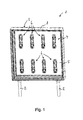
- the lighting arrangement 1 comprises a substantially cuboidal housing 3 with an opening closed by a lens 4 and a holding module 5 provided in the housing 3. On the holding module 5 is spaced from each other a plurality of light modules 6 fixed.
- the housing 3 comprises a shutter 4 which carries the lens 4.
- the closure flap is in particular held pivotably in relation to a frame 7 of the housing 3, so that when the closure flap is pivoted away the light modules 6 are accessible through the then released opening.
- the light modules 6 are provided for substantially homogeneous illumination of a region of the lens 4 provided for representing information.
- the detail view Fig. 2 makes it clear that each light module 6, a substantially rectangular portion 8 of the lens 4 is illuminated.
- the light modules 6 are set so far apart on the holding module 5 that is completely illuminated by the totality of the light modules 6 provided for the presentation of information area of the lens 4.
- the arrangement of the light modules 6 on the holding module 5 is preferably uniform or regular. Particularly preferably, the light modules 6 are arranged in a matrix-like manner on the holding module 5.
- the holding module 5 itself is, for example, disc-shaped and flat extending.
- the lens 4 and the holding module 5 are oriented substantially parallel to each other and have a constant distance.
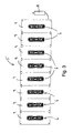
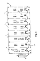
- the Fig. 3 and 4 show a holding module 5, which is formed from a plurality of identical holding body 9.
- the total of eight holding body 9 are joined together without spacing and each carry a light module 6.
- the holding module 5 formed from the plurality of holding bodies 9 has a common electrical connection element 10. Via the common electrical connection element 10 and a connecting line 11, the light modules 6 fixed to the holding bodies 9 are electrically contacted.
- the holding body 9, which are connected to the holding module 5, have a rectangular base.
- a size of the base area can correspond in particular to the size of the partial area 8 of the light disk 4 which is homogeneously illuminated by the light module 6 fixed to the individual holder body 9, when the holding body 9 is joined to the holding module 5 without spacing.
- the holding body 9 can be arranged one above the other in several rows.
- a plurality of light modules 6 can be fixed to a holding body 9.
- the Fig. 5 and 6 show a tool-free installation of the light module 6 on the holding body 9.
- the mounting position of the light module 6 on the holding body 7 is in Fig. 7 shown.
- a total of four designed according to the type of elastic fastening arms fasteners 12 are provided.
- a nose-shaped positioning means 13 is realized at a free end of the elastically formed attachment arms 12.
- the flat, extended holding body 9 has four fastening longitudinal recesses 14 and four positioning recesses 15.
- an electrical contact between an electrical contact element 17 provided on the light module 6 and an electrical counter contact element 18 fixed to the holding body 9 is produced.
- the mating contact element 18 is connected in an electrically conductive manner to the connection element 10 via the connection line 11.
- An electrical contacting of the light module 6 takes place insofar in the mounting position independently. Tools are not required for fixing the light module 6 on the holding body 9 nor for electrical contacting of the light module 6.
- the light module 6 itself comprises as essential components a support plate 19 with a plurality of light-emitting diodes 20 fixed thereon as light sources and with the electrical contact element 17, a module housing 21 and a seal 22 provided between the module housing 21 and the support plate 19.
- the module housing 21 has Part thereof a lens with a light exit surface made of an optically transparent material.
- An optical element 23 assigned to the light-emitting diodes 20 is designed as an example in the manner of a refractive optical system. The light emitted by the light-emitting diodes 20 is distributed by the optical element 23 such that the light module 6 associated sub-area 8 of the lens 4 is substantially homogeneously illuminated.
- the housing 3 of the lighting arrangement 1 may be formed as an encapsulated or sealed housing.
- the housing 3 can be designed as a housing 3 sealed in accordance with the protection class IP54, preferably in accordance with the protection class IP55.
- the fastening arms 12 of the light module 6 are provided on a rear side 25 of the light module 6 facing the holding bodies 9.
- the rear side 25 of the light module 6 is at least partially flat or for engagement with the holding body 9 just trained.
- One of the rear side 25 of the light module 6 opposite front side 26 thereof has the lens with the light exit surface.
- the size of the holding module 5 and in particular of the area provided for displaying information of the lens 4 can be selected almost completely free.
- the number of laterally adjacent or stacked light modules 6 can be selected according to the respective information requirements.
- a connection to the size of conventional bulbs, for example, to the length of commercially available fluorescent tubes is not required in this respect.
- the light module 6 is realized as an elongate light module 6 and the light module 6 is oriented vertically with regard to its elongate shape, this is merely an example.
- the light module 6 can be arbitrarily shaped in consideration of the optical or lighting requirements and, for example, fixed horizontally or in a different orientation on the holding module 5.
- the light module 6 is screwed or clipped to the holding module 5.
- the electrical contacting can take place in a separate assembly step before or after the fixing of the light module 6 to the holding module 5.
Landscapes
- Physics & Mathematics (AREA)
- General Physics & Mathematics (AREA)
- Engineering & Computer Science (AREA)
- Theoretical Computer Science (AREA)
- Arrangement Of Elements, Cooling, Sealing, Or The Like Of Lighting Devices (AREA)
- Non-Portable Lighting Devices Or Systems Thereof (AREA)
Abstract
Description
- Die Erfindung betrifft eine Beleuchtungsanordnung für Informationstafeln umfassend eine Mehrzahl von Lichtquellen, eine Lichtscheibe, durch die hindurch Licht der Lichtquellen abgestrahlt wird.
- Eine gattungsgemäße Beleuchtungsanordnung für Informationstafeln ist aus der
US 4,905,390 A bekannt. Sie dient insbesondere zur Anzeige von Informationen auf dem Flugfeld eines Flughafens. Die Beleuchtungsanordnung sieht ein im Wesentlichen quaderförmiges Gehäuse mit zwei gegenüberliegenden Öffnungen sowie den Öffnungen zugeordnete Verschlussklappen zum Verschließen der Öffnungen vor. In dem Gehäuse sind drei beabstandet zueinander angeordnete, horizontal erstreckte Leuchtstoffröhren als Lichtquellen vorgesehen. Als Teil der Verschlussklappen sind Lichtscheiben vorgesehen. Durch die Lichtscheibe hindurch wird das Licht der Lichtquellen abgestrahlt. Wenigstens ein Bereich der Lichtscheibe trägt die darzustellende Information. - Aufgabe der Erfindung ist es, eine skalierbare Beleuchtungsanordnung für Informationstafeln anzugeben, welche modular aufgebaut ist und hinsichtlich ihrer Größe variabel gestaltet werden kann.
- Zur Lösung der Aufgabe ist die Erfindung in Verbindung mit dem Oberbegriff des Patentanspruchs 1 dadurch gekennzeichnet, dass ein flächig erstrecktes und im Wesentlichen parallel zu der Lichtscheibe orientiertes Haltemodul sowie eine Mehrzahl von Lichtmodulen vorgesehen sind, wobei die Lichtmodule jeweils wenigstens eine Leuchtdiode als Lichtquelle und ein Optikelement zum Formen und Umlenken von Licht der Leuchtdiode in Richtung der Lichtscheibe aufweisen und wobei die Lichtmodule mit der jeweils wenigstens einen Leuchtdiode und dem Optikelement derart beabstandet an dem Haltemodul festlegbar sind, dass je Lichtmodul ein im Wesentlichen rechteckiger Teilbereich der Lichtscheibe und durch die Gesamtheit der Lichtmodule ein zur Darstellung von Informationen vorgesehener Bereich der Lichtscheibe vollständig und im Wesentlichen homogen ausgeleuchtet ist.
- Der besondere Vorteil der Erfindung besteht darin, dass eine Mehrzahl von LEDbasierten Lichtmodulen zur Hinterleuchtung der Lichtscheibe vorgesehen wird. Da jedes Lichtmodul einen Teilbereich der Lichtscheibe hinterleuchtet und die Lichtmodule gemeinsam den zur Darstellung der Information vorgesehenen Bereich der Lichtscheibe vollständig ausleuchten, kann durch die Anzahl der horizontal beziehungsweise vertikal benachbarten Lichtmodule eine Beleuchtungsanordnung beliebiger Größe geschaffen werden. Die Hinterleuchtung ist hierbei gleichermaßen homogen, da jedes Lichtmodul den ihm zugeordneten Teilbereich der Lichtscheibe homogen ausleuchtet. Das zur Ausleuchtung eines im Wesentlichen rechteckigen Teilbereichs der Lichtscheibe ausgebildete Optikelement kann beispielsweise durch einen Reflektor, insbesondere einen Freiformflächenreflektor, realisiert sein, welcher der Leuchtdiode zugeordnet ist. Der Reflektor ist beispielsweise so geformt, dass von der wenigstens einen Leuchtdiode abgestrahltes Licht in Richtung der Lichtscheibe reflektiert wird und die geforderte homogene Lichtverteilung geformt wird. Beispielsweise kann eine refraktive Optik realisiert sein zur homogenen Ausleuchtung des im Wesentlichen rechteckigen Teilbereichs der Lichtscheibe.
- Das Lichtmodul kann neben der wenigstens einen Leuchtdiode und dem Optikelement eine die Leuchtdiode aufweisende Trägerplatte sowie ein elektrisches Kontaktelement umfassen, welches elektrisch leitend mit der wenigstens einen Leuchtdiode verbunden ist. Ferner ist ein Modulgehäuse des Lichtmoduls und als Teil des Modulgehäuses eine die Leuchtdiode überdeckende Abschlussscheibe mit einer Lichtaustrittsfläche aus einem lichtdurchlässigen Werkstoff vorgesehen. Über die Lichtaustrittsfläche wird das von der wenigstens einen Leuchtdiode emittierte und an dem Optikelement umgelenkte Licht abgestrahlt. Die Trägerplatte ist insbesondere an dem Modulgehäuse des Lichtmoduls abgestützt. Beispielsweise ist die Lichtaustrittsfläche optikbehaftet ausgebildet. Das von der wenigstens einen Leuchtdiode in Richtung der Lichtaustrittsfläche abgesandte Licht wird beim Durchtreten der Lichtaustrittsfläche umgelenkt, insbesondere gebündelt beziehungsweise gestreut.
- Nach einer bevorzugten Ausführungsform der Erfindung ist das Optikelement des Lichtmoduls durch die optikbehaftete Lichtaustrittsfläche der Abschlussscheibe gebildet. Ebenso kann vorgesehen sein, dass die optikbehaftete Lichtaustrittsfläche als ein optisch wirksamer Teil des Optikelements realisiert ist. Vorteilhaft kann hierdurch auf das Vorsehen eines separaten Optikelements verzichtet werden. Stattdessen wird die Optik als Teil des Modulgehäuses realisiert. Insgesamt reduziert sich hierdurch die Anzahl der Bauteile des Lichtmoduls. Beispielsweise können als Bauteile des Lichtmoduls die mit der Leuchtdiode bestückte Trägerplatte, das Modulgehäuse sowie eine zwischen der Trägerplatte einerseits und dem Modulgehäuse andererseits vorgesehene Dichtung realisiert werden. Das Lichtmodul selbst umfasst dann lediglich drei Funktionskomponenten, die einfach und preisgünstig zu montieren sind.
- Ein zwischen dem Modulgehäuse und der Trägerplatte gebildeter, wenigstens eine Leuchtdiode aufnehmender Zwischenraum kann durch das Vorsehen der Dichtung gemäß der Schutzklasse IP64 gekapselt ausgebildet sein. Die Leuchtdiode selbst sowie die Trägerplatte sind insofern vor Witterungseinflüssen geschützt. Der Schutz besteht selbst dann, wenn ein äußeres Gehäuse der Beleuchtungsanordnung beispielsweise durch beim Start eines Flugzeugs aufgewirbelte Steine oder andere Fremdkörper beschädigt wird.
- Nach einer Weiterbildung der Erfindung ist an dem Lichtmodul wenigstens ein Befestigungselement vorgesehen zum Festlegen des Lichtmoduls an dem Haltemodul. Beispielsweise ist als Befestigungselement ein elastisch ausgebildeter Befestigungsarm realisiert. Bevorzugt werden wenigstens zwei elastische Befestigungsarme zueinander beabstandet an dem Lichtmodul vorgesehen. Das Haltemodul weist dabei für jedes Lichtmodul wenigstens zwei in korrespondierendem Abstand ausgebildete Befestigungslängsausnehmungen auf, in die das Lichtmodul mit den Befestigungselementen voran eingesetzt wird. Zum Verbringen des Lichtmoduls in eine Montageposition wird das Lichtmodul relativ zum Haltemodul in eine durch die Orientierung der Längsausnehmungen vorgegebene Montagerichtung linear verschoben, wobei die elastischen Haltearme durch die Befestigungslängsausnehmungen geführt werden und das Haltemodul umgreifen. Vorteilhaft ergibt sich hierdurch die Möglichkeit, die Lichtmodule in einfacher Weise an dem Haltemodul festzulegen. Es vereinfacht sich insofern die Montage der Beleuchtungsanordnung, und der Austausch von Lichtmodulen kann vor Ort auf dem Flugfeld schnell und sicher und insbesondere werkzeuglos durchgeführt werden.
- Nach einer Weiterbildung der Erfindung ist an dem Haltemodul je Lichtmodul ein mit den elektrischen Kontaktelementen des Lichtmoduls verbindbares elektrisches Gegenkontaktelement vorgesehen. Das elektrische Gegenkontaktelement ist an dem Haltemodul relativ zur Lage der Befestigungslängsausnehmungen derart vorgesehen, dass in der Montageposition des Lichtmoduls der elektrische Kontakt zwischen dem elektrischen Kontaktelement des Lichtmoduls einerseits und dem an dem Haltemodul vorgesehenen elektrischen Gegenkontaktelement andererseits hergestellt ist. Vorteilhaft kann auch die elektrische Kontaktierung werkzeuglos und unmittelbar bei der Montage des Lichtmoduls in einfacher Weise hergestellt werden. Zudem kann auf elektrische Steckkontakte verzichtet werden, bei denen die Gefahr einer Verpolung besteht beziehungsweise ein elektrischer Kontakt mangels mechanischer Verbindung der Steckkontakte unerkannt nicht hergestellt ist.
- Nach einer Weiterbildung der Erfindung ist an dem Lichtmodul ein Positioniermittel, insbesondere eine Positioniernase, ausgebildet. Weiter ist an dem Haltemodul je Lichtmodul ein weiteres Positioniermittel, insbesondere eine Positionierausnehmung, vorgesehen derart, dass in der Montageposition des Lichtmoduls zwischen dem Positioniermittel des Lichtmoduls und dem Positioniermittel des Haltemoduls eine Wirkverbindung hergestellt ist zum formschlüssigen und/oder kraftschlüssigen Festlegen des Lichtmoduls an dem Haltemodul. Vorteilhaft kann durch das Vorsehen der Positioniermittel an dem Lichtmodul und dem Haltemodul etwa durch eine Schwergängigkeit oder ein mechanisches Einrasten eine definierte Montageposition hergestellt werden. Die Befestigung der Lichtmodule an dem Haltemodul wird hierdurch weiter vereinfacht und einer Fehlmontage ist vorgebeugt. Beispielsweise kann die Positionierung über einen Anschlag realisiert werden.
- Nach einer Weiterbildung der Erfindung weist das Haltemodul eine Mehrzahl von miteinander verbundenen Haltekörpern auf. Je Haltekörper des Haltemoduls kann beispielsweise genau ein Lichtmodul festgelegt sein. Vorteilhaft kann durch das modulare Gestalten des Haltemoduls aus einer Mehrzahl von Haltekörpern die Größe der Beleuchtungsanordnung sehr variabel und bedarfsgerecht festgelegt werden. Die Haltekörper werden beispielsweise miteinander verbunden beziehungsweise aneinander festgelegt. Es kann vorgesehen sein, dass die Haltekörper abstandslos oder beabstandet zueinander vorgesehen werden. Insbesondere können an den Haltekörpern Montagemittel vorgesehen werden, welche das Verbinden der Haltekörper untereinander oder das Festlegen der Haltekörper an einem Traggerüst des Haltemoduls vereinfachen.
- Aus den weiteren Unteransprüchen und der nachfolgenden Beschreibung sind weitere Vorteile, Merkmale und Einzelheiten der Erfindung zu entnehmen. Dort erwähnte Merkmale können jeweils einzeln für sich oder auch in beliebiger Kombination erfindungswesentlich sein. Die Zeichnungen dienen lediglich beispielhaft der Klarstellung der Erfindung und haben keinen einschränkenden Charakter.
- Anhand der beigefügten Zeichnungen wird die Erfindung nachfolgend näher erläutert. Dabei zeigt:
- Fig. 1
- eine perspektivische Darstellung einer Informationstafel für ein Flugfeld mit einer erfindungsgemäßen Beleuchtungsanordnung,
- Fig. 2
- eine Aufsicht auf einen Teilbereich der Beleuchtungsanordnung nach
Fig. 1 , - Fig. 3
- eine Vorderansicht eines eine Mehrzahl von Haltekörpern aufweisenden Haltemoduls einer erfindungsgemäßen Beleuchtungsanordnung,
- Fig. 4
- eine Rückansicht des Haltemoduls nach
Fig. 3 , - Fig. 5
- eine Montagezeichnung eines Haltekörpers und eines hieran festzulegenden Lichtmoduls,
- Fig. 6
- eine Seitenansicht der Montagesituation nach
Fig. 5 und - Fig. 7
- eine perspektivische Teilschnittdarstellung eines an einem Haltekörper des Haltemoduls festgelegten Lichtmoduls.
- Eine Informationstafel nach den
Fig. 1 und2 wird beispielsweise auf dem Flugfeld verwendet zur Darstellung von Informationen. Als Teil der Informationstafel ist eine Beleuchtungsanordnung 1 vorgesehen sowie Füße 2 zum Aufstellen der Beleuchtungsanordnung 1. Die Beleuchtungsanordnung 1 umfasst ein im Wesentlichen quaderförmiges Gehäuse 3 mit einer durch eine Lichtscheibe 4 verschlossene Öffnung sowie ein in dem Gehäuse 3 vorgesehenes Haltemodul 5. An dem Haltemodul 5 ist zueinander beabstandet eine Mehrzahl von Lichtmodulen 6 festgelegt. Beispielsweise umfasst das Gehäuse 3 eine die Lichtscheibe 4 tragende Verschlussklappe. Die Verschlussklappe ist insbesondere schwenkbar in Bezug zu einem Rahmen 7 des Gehäuses 3 gehalten, sodass beim Wegschwenken der Verschlussklappe die Lichtmodule 6 durch die dann freigegebene Öffnung zugänglich sind. - Die Lichtmodule 6 sind vorgesehen zur im Wesentlichen homogenen Ausleuchtung eines zur Darstellung von Informationen vorgesehenen Bereichs der Lichtscheibe 4. Die Detailansicht nach
Fig. 2 macht deutlich, dass je Lichtmodul 6 ein im Wesentlichen rechteckiger Teilbereich 8 der Lichtscheibe 4 ausgeleuchtet wird. Die Lichtmodule 6 sind insofern derart beabstandet an dem Haltemodul 5 festgelegt, dass durch die Gesamtheit der Lichtmodule 6 der für die Darstellung von Informationen vorgesehene Bereich der Lichtscheibe 4 vollständig ausgeleuchtet ist. Die Anordnung der Lichtmodule 6 an dem Haltemodul 5 erfolgt insofern bevorzugt gleichmäßig beziehungsweise regelmäßig. Besonders bevorzugt werden die Lichtmodule 6 matrixartig an dem Haltemodul 5 angeordnet. Das Haltemodul 5 selbst ist beispielsweise scheibenförmig und flach erstreckt vorgesehen. Beispielsweise sind die Lichtscheibe 4 und das Haltemodul 5 im Wesentlichen parallel zueinander orientiert und weisen einen konstanten Abstand auf. - Die
Fig. 3 und4 zeigen ein Haltemodul 5, welches aus einer Mehrzahl identischer Haltekörper 9 gebildet ist. Die insgesamt acht Haltekörper 9 sind abstandslos aneinandergefügt und tragen jeweils ein Lichtmodul 6. Wie insbesondere aus der Rückansicht nachFig. 4 deutlich wird, weist das aus der Mehrzahl von Haltekörpern 9 gebildete Haltemodul 5 ein gemeinsames elektrisches Anschlusselement 10 auf. Über das gemeinsame elektrische Anschlusselement 10 und eine Anschlussleitung 11 sind die an den Haltekörpern 9 festgelegten Lichtmodule 6 elektrisch kontaktiert. - Die Haltekörper 9, die zu dem Haltemodul 5 verbunden sind, weisen eine rechteckige Grundfläche auf. Eine Größe der Grundfläche kann insbesondere beim abstandslosen Verbinden der Haltekörper 9 zum Haltemodul 5 zu der Größe des von dem an dem einzelnen Haltekörper 9 festgelegten Lichtmodul 6 homogen ausgeleuchteten Teilbereichs 8 der Lichtscheibe 4 korrespondieren. Selbstverständlich können die Haltekörper 9 in mehreren Reihen übereinander angeordnet werden.
- Nach einer nicht dargestellten Ausführungsform der Erfindung kann an einem Haltekörper 9 eine Mehrzahl von Lichtmodulen 6 festgelegt werden.
- Die
Fig. 5 und6 zeigen eine werkzeuglose Montage des Lichtmoduls 6 an dem Haltekörper 9. Die Montageposition des Lichtmoduls 6 an dem Haltekörper 7 ist inFig. 7 dargestellt. An dem Lichtmodul 6 sind zueinander beanstandet insgesamt vier nach Art elastischer Befestigungsarme ausgebildeter Befestigungselemente 12 vorgesehen. Ferner ist an einem freien Ende der elastisch ausgebildeten Befestigungsarme 12 ein nasenförmig ausgeformtes Positioniermittel 13 realisiert. Korrespondierend zu den Befestigungsarmen 12 und der Positioniernase 13 sind dem flach erstreckten Haltekörper 9 vier Befestigungslängsausnehmungen 14 sowie vier Positionierausnehmungen 15 vorgesehen. - Zum Festlegen des Lichtmoduls 6 an dem Haltekörper 9 wird dieses mit den elastischen Befestigungsarmen 12 voran in die Befestigungslängsausnehmungen 14 eingesetzt. Durch Linearverschiebung des Lichtmoduls 6 in eine Montagerichtung 16 wird das Lichtmodul 6 in eine Montageposition desselben verbracht. Hierbei umgreifen die elastischen Befestigungsarme 12 den Haltekörper 9. Zugleich greifen die Positionsnasen 13 des Lichtmoduls in den Positionierausnehmungen 15 des Haltekörpers 9. Es ergibt sich insofern eine definierte Montageposition für das Lichtmodul 6 an dem Haltekörper 9.
- In der Montageposition wird neben der mechanischen Festlegung des Lichtmoduls 6 an dem Haltekörper 9 des Haltemoduls 5 ein elektrischer Kontakt zwischen einem an dem Lichtmodul 6 vorgesehenen elektrischen Kontaktelement 17 und einem an dem Haltekörper 9 festgelegten elektrischen Gegenkontaktelement 18 hergestellt. Das Gegenkontaktelement 18 ist dabei über die Anschlussleitung 11 elektrisch leitend mit dem Anschlusselement 10 verbunden. Eine elektrische Kontaktierung des Lichtmoduls 6 erfolgt insofern in der Montageposition selbstständig. Werkzeuge sind weder zum Festlegen des Lichtmoduls 6 an dem Haltekörper 9 noch zur elektrischen Kontaktierung des Lichtmoduls 6 erforderlich.
- Das Lichtmodul 6 selbst umfasst als wesentliche Komponenten eine Trägerplatte 19 mit einer Mehrzahl von darauf festgelegten Leuchtdioden 20 als Lichtquellen und mit dem elektrischen Kontaktelement 17, ein Modulgehäuse 21 und eine zwischen dem Modulgehäuse 21 und der Trägerplatte 19 vorgesehene Dichtung 22. Das Modulgehäuse 21 weist als Teil desselben eine Abschlussscheibe mit einer Lichtaustrittsfläche aus einem optisch transparenten Werkstoff auf. Ein den Leuchtdioden 20 zugeordnetes Optikelement 23 ist exemplarisch nach Art einer refraktiven Optik ausgebildet. Das von den Leuchtdioden 20 ausgesandte Licht wird von dem Optikelement 23 derart verteilt, dass der dem Lichtmodul 6 zugeordnete Teilbereich 8 der Lichtscheibe 4 im Wesentlichen homogen ausgeleuchtet ist.
- Die zwischen der Trägerplatte 19 und dem Modulgehäuse 21 vorgesehene Dichtung 22 dichtet einen die Leuchtdiode 20 aufnehmenden Zwischenraum 24 des Lichtmoduls 6 nach Art der Schutzklasse IP64. Zusätzlich kann das Gehäuse 3 der Beleuchtungsanordnung 1 als gekapseltes beziehungsweise abgedichtetes Gehäuse ausgebildet sein. Beispielsweise kann das Gehäuse 3 - sofern die Öffnungen durch die Verschlussklappe geschlossen sind - als ein gemäß der Schutzklasse IP54, bevorzugt gemäß der Schutzklasse IP55 gedichtetes Gehäuse 3 ausgebildet sein.
- Die Befestigungsarme 12 des Lichtmoduls 6 sind auf einer den Haltekörpern 9 zugewandten Rückseite 25 des Lichtmoduls 6 vorgesehen. Die Rückseite 25 des Lichtmoduls 6 ist zur Anlage an dem Haltekörper 9 zumindest abschnittsweise flächig beziehungsweise eben ausgebildet. Eine der Rückseite 25 des Lichtmoduls 6 gegenüberliegende Vorderseite 26 desselben weist die Abschlussscheibe mit der Lichtaustrittsfläche auf.
- Unabhängig davon, ob das Haltemodul 5 einstückig ausgebildet ist oder durch eine Mehrzahl von miteinander verbundenen Haltekörpern 9 gebildet wird, können die Größe des Haltemoduls 5 und insbesondere des zur Darstellung von Informationen vorgesehenen Bereichs der Lichtscheibe 4 nahezu vollständig frei gewählt werden. Insbesondere kann die Anzahl der seitlich benachbarten beziehungsweise übereinander angeordneten Lichtmodule 6 entsprechend des jeweiligen Informationsbedarfs gewählt werden. Eine Bindung an die Größe konventioneller Leuchtmittel, beispielsweise an die Baulänge von handelsüblichen Leuchtstoffröhren, ist insofern nicht erforderlich.
- Sofern in den Ausführungsbeispielen das Lichtmodul 6 als langgestrecktes Lichtmodul 6 realisiert ist und das Lichtmodul 6 hinsichtlich seiner langgestreckten Form vertikal orientiert wird, ist dies lediglich beispielhaft. Selbstverständlich kann das Lichtmodul 6 bei Beachtung der optischen beziehungsweise lichttechnischen Erfordernisse beliebig geformt und beispielsweise horizontal oder in einer anderen Orientierung am Haltemodul 5 festgelegt werden.
- Nach einer nicht dargestellten Ausführungsform der Erfindung kann das Lichtmodul 6 an dem Haltemodul 5 verschraubt oder eingeklipst wird. Die elektrische Kontaktierung kann in einem separaten Montageschritt vor oder nach dem Festlegen des Lichtmoduls 6 an dem Haltemodul 5 erfolgen.
- Gleiche Bauteile und Bauteilfunktionen sind durch gleiche Bezugszeichen gekennzeichnet.
-
- 1
- Beleuchtungsanordnung
- 2
- Fuß
- 3
- Gehäuse
- 4
- Lichtscheibe
- 5
- Haltemodul
- 6
- Lichtmodul
- 7
- Rahmen
- 8
- Teilbereich
- 9
- Haltekörper
- 10
- Anschlusselement
- 11
- Anschlussleitung
- 12
- Befestigungsarm
- 13
- Positioniernase
- 14
- Befestigungslängsausnehmung
- 15
- Positionierausnehmung
- 16
- Montagerichtung
- 17
- elektrisches Kontaktelement
- 18
- elektrisches Gegenkontaktelement
- 19
- Trägerplatte
- 20
- Leuchtdiode
- 21
- Modulgehäuse
- 22
- Dichtung
- 23
- Optikelement
- 24
- Zwischenraum
- 25
- Rückseite
- 26
- Vorderseite
Claims (10)
- Beleuchtungsanordnung (1) für Informationstafeln umfassend- eine Mehrzahl von Lichtquellen (Leuchtdiode 20),- eine Lichtscheibe (4), durch die hindurch Licht der Lichtquellen (Leuchtdiode 20) abgestrahlt wird,dadurch gekennzeichnet, dass ein flächig erstrecktes und im Wesentlichen parallel zu der Lichtscheibe (4) orientiertes Haltemodul (5) sowie eine Mehrzahl von Lichtmodulen (6) vorgesehen sind,- wobei die Lichtmodule (6) jeweils wenigstens eine Leuchtdiode (20) als Lichtquelle und ein Optikelement (23) zum Formen und Umlenken von Licht der Leuchtdiode (20) in Richtung der Lichtscheibe (4) aufweisen und- wobei die Lichtmodule (6) mit der jeweils wenigstens einen Leuchtdiode (20) und dem Optikelement (23) derart beabstandet an dem Haltemodul (5) festlegbar sind, dass je Lichtmodul (6) ein im Wesentlichen rechteckiger Teilbereich (8) der Lichtscheibe (4) und durch die Gesamtheit der Lichtmodule (6) ein zur Darstellung von Informationen vorgesehener Bereich der Lichtscheibe (4) vollständig und im Wesentlichen homogen ausgeleuchtet ist.
- Beleuchtungsanordnung (1) nach Anspruch 1, dadurch gekennzeichnet, dass das Optikelement (23) des Lichtmoduls (6) durch eine optikbehaftete Lichtaustrittsfläche gebildet ist, welche an einer Abschlussscheibe eines Modulgehäuses (21) des Lichtmoduls (6) vorgesehen ist, und/oder das die optikbehaftete Lichtaustrittsfläche als ein optisch wirksamer Teil des Optikelements (23) realisiert.
- Beleuchtungsanordnung (1) nach Anspruch 1 oder 2, dadurch gekennzeichnet, dass das Modulgehäuse (21) des Lichtmoduls (6) und eine die wenigstens eine Leuchtdiode (20) tragenden Trägerplatte (19) wenigstens abschnittsweise geschlossen ausgebildet sind und dass zwischen der Trägerplatte (19) einerseits und dem Modulgehäuse (21) andererseits eine Dichtung (22) vorgesehen ist derart, dass ein zwischen dem Modulgehäuse (21) und der Trägerplatte (19) gebildeter, die wenigstens eine Leuchtdiode (20) aufnehmender Zwischenraum (24) nach Art eines gemäß der Schutzklasse IP64 gekapselten Zwischenraums (24) ausgebildet ist.
- Beleuchtungsanordnung (1) nach einem der Ansprüche 1 bis 3, dadurch gekennzeichnet, dass an dem Lichtmodul (6) wenigstens ein Befestigungselement, insbesondere ein elastisch ausgebildeter Befestigungsarm (12), vorgesehen ist zum Festlegen des Lichtmoduls (6) dem Haltemodul (5).
- Beleuchtungsanordnung (1) nach einem der Ansprüche 1 bis 4, dadurch gekennzeichnet, dass wenigstens zwei elastische Befestigungsarme (12) an dem Lichtmodul (6) zueinander beabstandet vorgesehen sind und dass an dem Haltemodul (5) je Lichtmodul (6) wenigstens zwei in korrespondierendem Abstand ausgebildete Befestigungslängsausnehmungen (14) derart vorgesehen sind, dass das Lichtmodul (6) zum Verbringen desselben in eine Montageposition mit den elastischen Befestigungsarmen (12) in die Befestigungslängsausnehmung (14) eingesetzt und durch Linearverschiebung in eine Montagerichtung (16) an dem Haltemodul (5) festgelegt wird, wobei die elastischen Befestigungsarme (12) durch die Befestigungslängsausnehmung (14) geführt sind und das Haltemodul (5) umgreifen.
- Beleuchtungsanordnung (1) nach einem der Ansprüche 1 bis 5, dadurch gekennzeichnet, dass das Lichtmodul (6) ein mit der wenigstens einen Leuchtdiode (20) leitend verbundenes Kontaktelement (17) aufweist und dass an dem Haltemodul (5) je Lichtmodul (6) ein mit dem elektrischen Kontaktelement (17) des Lichtmoduls (6) verbindbares elektrisches Gegenkontaktelement (18) vorgesehen ist, wobei das elektrische Gegenkontaktelement (18) an dem Haltemodul (5) relativ zu den Befestigungslängsausnehmungen (14) derart vorgesehen ist, dass in der Montageposition des Lichtmoduls (6) ein elektrischer Kontakt zwischen dem elektrischen Kontaktelement (17) des Lichtmoduls (6) und dem an dem Haltemodul (5) vorgesehenen elektrischen Gegenkontaktelement (18) hergestellt ist.
- Beleuchtungsanordnung (1) nach einem der Ansprüche 1 bis 6, dadurch gekennzeichnet, dass an dem Lichtmodul (6) ein Positioniermittel, insbesondere eine Positioniernase (13), ausgebildet ist und dass an dem Haltemodul (5) je Lichtmodul (6) ein weiteres Positioniermittel, insbesondere eine Positionierausnehmung (15), vorgesehen ist derart, dass in der Montageposition eine Wirkverbindung zwischen dem Positioniermittel (Positioniemase 13) des Lichtmoduls (6) und dem Positioniermittel (Positionierausnehmung 15) des Haltemoduls (5) hergestellt ist.
- Beleuchtungsanordnung (1) nach einem der Ansprüche 1 bis 7, dadurch gekennzeichnet, dass das Haltemodul (5) eine Mehrzahl von miteinander verbundenen Haltekörpern (9) aufweist und/oder dass je Haltekörper (9) des Haltemoduls (5) ein Lichtmodul (6) festgelegt ist.
- Beleuchtungsanordnung (1) nach Anspruch 8, dadurch gekennzeichnet, dass das Haltemodul (5) eine Mehrzahl identischer Haltekörper (9) aufweist.
- Beleuchtungsanordnung (1) nach einem der Ansprüche 1 bis 9, dadurch gekennzeichnet, dass das Lichtmodul (6) langgestreckt ausgebildet und bevorzugt vertikal orientiert an dem Haltemodul (5) festgelegt ist.
Priority Applications (2)
| Application Number | Priority Date | Filing Date | Title |
|---|---|---|---|
| EP13187493.5A EP2858063B1 (de) | 2013-10-07 | 2013-10-07 | Beleuchtungsanordnung für Informationstafeln |
| PCT/EP2014/067483 WO2015051938A1 (de) | 2013-10-07 | 2014-08-15 | Beleuchtungsanordnung für informationstafeln |
Applications Claiming Priority (1)
| Application Number | Priority Date | Filing Date | Title |
|---|---|---|---|
| EP13187493.5A EP2858063B1 (de) | 2013-10-07 | 2013-10-07 | Beleuchtungsanordnung für Informationstafeln |
Publications (2)
| Publication Number | Publication Date |
|---|---|
| EP2858063A1 true EP2858063A1 (de) | 2015-04-08 |
| EP2858063B1 EP2858063B1 (de) | 2021-07-28 |
Family
ID=49304775
Family Applications (1)
| Application Number | Title | Priority Date | Filing Date |
|---|---|---|---|
| EP13187493.5A Active EP2858063B1 (de) | 2013-10-07 | 2013-10-07 | Beleuchtungsanordnung für Informationstafeln |
Country Status (2)
| Country | Link |
|---|---|
| EP (1) | EP2858063B1 (de) |
| WO (1) | WO2015051938A1 (de) |
Citations (4)
| Publication number | Priority date | Publication date | Assignee | Title |
|---|---|---|---|---|
| US4905390A (en) | 1987-12-07 | 1990-03-06 | Johann Stilling | Illuminated display |
| JP2006145890A (ja) * | 2004-11-19 | 2006-06-08 | Avix Inc | 大画面led表示システム |
| EP2110802A2 (de) * | 2008-04-18 | 2009-10-21 | Lumination, LLC | LED-Lichtmotor |
| KR20120052071A (ko) * | 2010-11-15 | 2012-05-23 | 주식회사 테크자인라이트패널 | 광고용 패널의 조명모듈 설치구조 |
-
2013
- 2013-10-07 EP EP13187493.5A patent/EP2858063B1/de active Active
-
2014
- 2014-08-15 WO PCT/EP2014/067483 patent/WO2015051938A1/de not_active Ceased
Patent Citations (4)
| Publication number | Priority date | Publication date | Assignee | Title |
|---|---|---|---|---|
| US4905390A (en) | 1987-12-07 | 1990-03-06 | Johann Stilling | Illuminated display |
| JP2006145890A (ja) * | 2004-11-19 | 2006-06-08 | Avix Inc | 大画面led表示システム |
| EP2110802A2 (de) * | 2008-04-18 | 2009-10-21 | Lumination, LLC | LED-Lichtmotor |
| KR20120052071A (ko) * | 2010-11-15 | 2012-05-23 | 주식회사 테크자인라이트패널 | 광고용 패널의 조명모듈 설치구조 |
Also Published As
| Publication number | Publication date |
|---|---|
| WO2015051938A1 (de) | 2015-04-16 |
| EP2858063B1 (de) | 2021-07-28 |
Similar Documents
| Publication | Publication Date | Title |
|---|---|---|
| EP3114403B1 (de) | Leuchte mit auswechselbaren leuchtmodulen | |
| DE102014100640A1 (de) | Vorrichtigung zum Laden eines elektrisch betreibbaren Fahrzeugs | |
| DE102007010023A1 (de) | Fahrzeugleuchte | |
| DE4243175A1 (de) | Beleuchtungseinrichtung | |
| DE102021106644A1 (de) | Abdeckung für ein Leuchtmittel sowie Leuchte mit Abdeckung | |
| WO2018149741A1 (de) | Beleuchtungsvorrichtung für ein innenausstattungsteil | |
| DE102016123907A1 (de) | Eine Beleuchtungsvorrichtung, insbesondere eine Signallampe, für Kraftfahrzeuge | |
| EP2863114A1 (de) | LED-Flächenleuchte | |
| EP2851609B1 (de) | Beleuchtungseinrichtung | |
| DE102017128620B4 (de) | Modulare LED-Leuchte | |
| EP2123976B1 (de) | Einbauleuchte | |
| DE202014100951U1 (de) | Leuchte mit Trägerelement und lösbar befestigbarem Leuchtmodul | |
| EP1818698A1 (de) | Beleuchtungseinrichtung für ein reflektierendes Schild, beleuchtete Schildanordnung sowie Halter | |
| DE102014212918A1 (de) | Kraftfahrzeug-Beleuchtungseinrichtung | |
| EP2994693B1 (de) | Abdeckungselement für flächenleuchte | |
| DE102010032946A1 (de) | Kraftfahrzeug mit einem Innenraum, in dem eine Beleuchtungseinrichtung angeordnet ist | |
| DE202021101384U1 (de) | Abdeckung für ein Leuchtmittel sowie Leuchte mit Abdeckung | |
| DE202006003392U1 (de) | Fahrzeugleuchte | |
| EP2873913A1 (de) | LED-Leuchte | |
| EP2858063B1 (de) | Beleuchtungsanordnung für Informationstafeln | |
| WO2011128030A1 (de) | Led-modul mit passiv-led | |
| EP3100909B1 (de) | Einsatzfahrzeug, insbesondere feuerwehrfahrzeug | |
| DE102008016675A1 (de) | Leuchtanordnung mit einem Lichtleiter und Leuchtdioden | |
| DE202012009365U1 (de) | LED-Leuchte | |
| DE102016104221A1 (de) | LED-Leuchte mit Lichtlenkelement |
Legal Events
| Date | Code | Title | Description |
|---|---|---|---|
| PUAI | Public reference made under article 153(3) epc to a published international application that has entered the european phase |
Free format text: ORIGINAL CODE: 0009012 |
|
| 17P | Request for examination filed |
Effective date: 20131007 |
|
| AK | Designated contracting states |
Kind code of ref document: A1 Designated state(s): AL AT BE BG CH CY CZ DE DK EE ES FI FR GB GR HR HU IE IS IT LI LT LU LV MC MK MT NL NO PL PT RO RS SE SI SK SM TR |
|
| AX | Request for extension of the european patent |
Extension state: BA ME |
|
| R17P | Request for examination filed (corrected) |
Effective date: 20150601 |
|
| RBV | Designated contracting states (corrected) |
Designated state(s): AL AT BE BG CH CY CZ DE DK EE ES FI FR GB GR HR HU IE IS IT LI LT LU LV MC MK MT NL NO PL PT RO RS SE SI SK SM TR |
|
| 17Q | First examination report despatched |
Effective date: 20160401 |
|
| STAA | Information on the status of an ep patent application or granted ep patent |
Free format text: STATUS: EXAMINATION IS IN PROGRESS |
|
| RAP1 | Party data changed (applicant data changed or rights of an application transferred) |
Owner name: INDUPERM A/S |
|
| GRAP | Despatch of communication of intention to grant a patent |
Free format text: ORIGINAL CODE: EPIDOSNIGR1 |
|
| STAA | Information on the status of an ep patent application or granted ep patent |
Free format text: STATUS: GRANT OF PATENT IS INTENDED |
|
| INTG | Intention to grant announced |
Effective date: 20210406 |
|
| GRAS | Grant fee paid |
Free format text: ORIGINAL CODE: EPIDOSNIGR3 |
|
| GRAA | (expected) grant |
Free format text: ORIGINAL CODE: 0009210 |
|
| STAA | Information on the status of an ep patent application or granted ep patent |
Free format text: STATUS: THE PATENT HAS BEEN GRANTED |
|
| AK | Designated contracting states |
Kind code of ref document: B1 Designated state(s): AL AT BE BG CH CY CZ DE DK EE ES FI FR GB GR HR HU IE IS IT LI LT LU LV MC MK MT NL NO PL PT RO RS SE SI SK SM TR |
|
| REG | Reference to a national code |
Ref country code: GB Ref legal event code: FG4D Free format text: NOT ENGLISH |
|
| REG | Reference to a national code |
Ref country code: CH Ref legal event code: EP |
|
| REG | Reference to a national code |
Ref country code: AT Ref legal event code: REF Ref document number: 1415411 Country of ref document: AT Kind code of ref document: T Effective date: 20210815 |
|
| REG | Reference to a national code |
Ref country code: IE Ref legal event code: FG4D Free format text: LANGUAGE OF EP DOCUMENT: GERMAN |
|
| REG | Reference to a national code |
Ref country code: DE Ref legal event code: R096 Ref document number: 502013015849 Country of ref document: DE |
|
| REG | Reference to a national code |
Ref country code: LT Ref legal event code: MG9D |
|
| REG | Reference to a national code |
Ref country code: NL Ref legal event code: MP Effective date: 20210728 |
|
| PG25 | Lapsed in a contracting state [announced via postgrant information from national office to epo] |
Ref country code: HR Free format text: LAPSE BECAUSE OF FAILURE TO SUBMIT A TRANSLATION OF THE DESCRIPTION OR TO PAY THE FEE WITHIN THE PRESCRIBED TIME-LIMIT Effective date: 20210728 Ref country code: SE Free format text: LAPSE BECAUSE OF FAILURE TO SUBMIT A TRANSLATION OF THE DESCRIPTION OR TO PAY THE FEE WITHIN THE PRESCRIBED TIME-LIMIT Effective date: 20210728 Ref country code: LT Free format text: LAPSE BECAUSE OF FAILURE TO SUBMIT A TRANSLATION OF THE DESCRIPTION OR TO PAY THE FEE WITHIN THE PRESCRIBED TIME-LIMIT Effective date: 20210728 Ref country code: BG Free format text: LAPSE BECAUSE OF FAILURE TO SUBMIT A TRANSLATION OF THE DESCRIPTION OR TO PAY THE FEE WITHIN THE PRESCRIBED TIME-LIMIT Effective date: 20211028 Ref country code: RS Free format text: LAPSE BECAUSE OF FAILURE TO SUBMIT A TRANSLATION OF THE DESCRIPTION OR TO PAY THE FEE WITHIN THE PRESCRIBED TIME-LIMIT Effective date: 20210728 Ref country code: PT Free format text: LAPSE BECAUSE OF FAILURE TO SUBMIT A TRANSLATION OF THE DESCRIPTION OR TO PAY THE FEE WITHIN THE PRESCRIBED TIME-LIMIT Effective date: 20211129 Ref country code: NL Free format text: LAPSE BECAUSE OF FAILURE TO SUBMIT A TRANSLATION OF THE DESCRIPTION OR TO PAY THE FEE WITHIN THE PRESCRIBED TIME-LIMIT Effective date: 20210728 Ref country code: NO Free format text: LAPSE BECAUSE OF FAILURE TO SUBMIT A TRANSLATION OF THE DESCRIPTION OR TO PAY THE FEE WITHIN THE PRESCRIBED TIME-LIMIT Effective date: 20211028 Ref country code: ES Free format text: LAPSE BECAUSE OF FAILURE TO SUBMIT A TRANSLATION OF THE DESCRIPTION OR TO PAY THE FEE WITHIN THE PRESCRIBED TIME-LIMIT Effective date: 20210728 Ref country code: FI Free format text: LAPSE BECAUSE OF FAILURE TO SUBMIT A TRANSLATION OF THE DESCRIPTION OR TO PAY THE FEE WITHIN THE PRESCRIBED TIME-LIMIT Effective date: 20210728 |
|
| PG25 | Lapsed in a contracting state [announced via postgrant information from national office to epo] |
Ref country code: PL Free format text: LAPSE BECAUSE OF FAILURE TO SUBMIT A TRANSLATION OF THE DESCRIPTION OR TO PAY THE FEE WITHIN THE PRESCRIBED TIME-LIMIT Effective date: 20210728 Ref country code: LV Free format text: LAPSE BECAUSE OF FAILURE TO SUBMIT A TRANSLATION OF THE DESCRIPTION OR TO PAY THE FEE WITHIN THE PRESCRIBED TIME-LIMIT Effective date: 20210728 Ref country code: GR Free format text: LAPSE BECAUSE OF FAILURE TO SUBMIT A TRANSLATION OF THE DESCRIPTION OR TO PAY THE FEE WITHIN THE PRESCRIBED TIME-LIMIT Effective date: 20211029 |
|
| PG25 | Lapsed in a contracting state [announced via postgrant information from national office to epo] |
Ref country code: DK Free format text: LAPSE BECAUSE OF FAILURE TO SUBMIT A TRANSLATION OF THE DESCRIPTION OR TO PAY THE FEE WITHIN THE PRESCRIBED TIME-LIMIT Effective date: 20210728 |
|
| REG | Reference to a national code |
Ref country code: DE Ref legal event code: R097 Ref document number: 502013015849 Country of ref document: DE |
|
| REG | Reference to a national code |
Ref country code: DE Ref legal event code: R119 Ref document number: 502013015849 Country of ref document: DE |
|
| REG | Reference to a national code |
Ref country code: CH Ref legal event code: PL |
|
| PG25 | Lapsed in a contracting state [announced via postgrant information from national office to epo] |
Ref country code: SM Free format text: LAPSE BECAUSE OF FAILURE TO SUBMIT A TRANSLATION OF THE DESCRIPTION OR TO PAY THE FEE WITHIN THE PRESCRIBED TIME-LIMIT Effective date: 20210728 Ref country code: SK Free format text: LAPSE BECAUSE OF FAILURE TO SUBMIT A TRANSLATION OF THE DESCRIPTION OR TO PAY THE FEE WITHIN THE PRESCRIBED TIME-LIMIT Effective date: 20210728 Ref country code: RO Free format text: LAPSE BECAUSE OF FAILURE TO SUBMIT A TRANSLATION OF THE DESCRIPTION OR TO PAY THE FEE WITHIN THE PRESCRIBED TIME-LIMIT Effective date: 20210728 Ref country code: EE Free format text: LAPSE BECAUSE OF FAILURE TO SUBMIT A TRANSLATION OF THE DESCRIPTION OR TO PAY THE FEE WITHIN THE PRESCRIBED TIME-LIMIT Effective date: 20210728 Ref country code: CZ Free format text: LAPSE BECAUSE OF FAILURE TO SUBMIT A TRANSLATION OF THE DESCRIPTION OR TO PAY THE FEE WITHIN THE PRESCRIBED TIME-LIMIT Effective date: 20210728 Ref country code: AL Free format text: LAPSE BECAUSE OF FAILURE TO SUBMIT A TRANSLATION OF THE DESCRIPTION OR TO PAY THE FEE WITHIN THE PRESCRIBED TIME-LIMIT Effective date: 20210728 |
|
| PLBE | No opposition filed within time limit |
Free format text: ORIGINAL CODE: 0009261 |
|
| STAA | Information on the status of an ep patent application or granted ep patent |
Free format text: STATUS: NO OPPOSITION FILED WITHIN TIME LIMIT |
|
| REG | Reference to a national code |
Ref country code: BE Ref legal event code: MM Effective date: 20211031 |
|
| GBPC | Gb: european patent ceased through non-payment of renewal fee |
Effective date: 20211028 |
|
| PG25 | Lapsed in a contracting state [announced via postgrant information from national office to epo] |
Ref country code: MC Free format text: LAPSE BECAUSE OF FAILURE TO SUBMIT A TRANSLATION OF THE DESCRIPTION OR TO PAY THE FEE WITHIN THE PRESCRIBED TIME-LIMIT Effective date: 20210728 |
|
| 26N | No opposition filed |
Effective date: 20220429 |
|
| PG25 | Lapsed in a contracting state [announced via postgrant information from national office to epo] |
Ref country code: LU Free format text: LAPSE BECAUSE OF NON-PAYMENT OF DUE FEES Effective date: 20211007 Ref country code: IT Free format text: LAPSE BECAUSE OF FAILURE TO SUBMIT A TRANSLATION OF THE DESCRIPTION OR TO PAY THE FEE WITHIN THE PRESCRIBED TIME-LIMIT Effective date: 20210728 Ref country code: GB Free format text: LAPSE BECAUSE OF NON-PAYMENT OF DUE FEES Effective date: 20211028 Ref country code: DE Free format text: LAPSE BECAUSE OF NON-PAYMENT OF DUE FEES Effective date: 20220503 Ref country code: BE Free format text: LAPSE BECAUSE OF NON-PAYMENT OF DUE FEES Effective date: 20211031 |
|
| PG25 | Lapsed in a contracting state [announced via postgrant information from national office to epo] |
Ref country code: LI Free format text: LAPSE BECAUSE OF NON-PAYMENT OF DUE FEES Effective date: 20211031 Ref country code: CH Free format text: LAPSE BECAUSE OF NON-PAYMENT OF DUE FEES Effective date: 20211031 |
|
| PG25 | Lapsed in a contracting state [announced via postgrant information from national office to epo] |
Ref country code: FR Free format text: LAPSE BECAUSE OF NON-PAYMENT OF DUE FEES Effective date: 20211031 |
|
| PG25 | Lapsed in a contracting state [announced via postgrant information from national office to epo] |
Ref country code: IE Free format text: LAPSE BECAUSE OF NON-PAYMENT OF DUE FEES Effective date: 20211007 |
|
| REG | Reference to a national code |
Ref country code: AT Ref legal event code: MM01 Ref document number: 1415411 Country of ref document: AT Kind code of ref document: T Effective date: 20211007 |
|
| PG25 | Lapsed in a contracting state [announced via postgrant information from national office to epo] |
Ref country code: AT Free format text: LAPSE BECAUSE OF NON-PAYMENT OF DUE FEES Effective date: 20211007 |
|
| PG25 | Lapsed in a contracting state [announced via postgrant information from national office to epo] |
Ref country code: HU Free format text: LAPSE BECAUSE OF FAILURE TO SUBMIT A TRANSLATION OF THE DESCRIPTION OR TO PAY THE FEE WITHIN THE PRESCRIBED TIME-LIMIT; INVALID AB INITIO Effective date: 20131007 |
|
| PG25 | Lapsed in a contracting state [announced via postgrant information from national office to epo] |
Ref country code: CY Free format text: LAPSE BECAUSE OF FAILURE TO SUBMIT A TRANSLATION OF THE DESCRIPTION OR TO PAY THE FEE WITHIN THE PRESCRIBED TIME-LIMIT Effective date: 20210728 |
|
| PG25 | Lapsed in a contracting state [announced via postgrant information from national office to epo] |
Ref country code: MK Free format text: LAPSE BECAUSE OF FAILURE TO SUBMIT A TRANSLATION OF THE DESCRIPTION OR TO PAY THE FEE WITHIN THE PRESCRIBED TIME-LIMIT Effective date: 20210728 |
|
| PG25 | Lapsed in a contracting state [announced via postgrant information from national office to epo] |
Ref country code: TR Free format text: LAPSE BECAUSE OF FAILURE TO SUBMIT A TRANSLATION OF THE DESCRIPTION OR TO PAY THE FEE WITHIN THE PRESCRIBED TIME-LIMIT Effective date: 20210728 |
|
| PG25 | Lapsed in a contracting state [announced via postgrant information from national office to epo] |
Ref country code: MT Free format text: LAPSE BECAUSE OF FAILURE TO SUBMIT A TRANSLATION OF THE DESCRIPTION OR TO PAY THE FEE WITHIN THE PRESCRIBED TIME-LIMIT Effective date: 20210728 |