EP2858043B1 - Filling machine for liquid and pourable goods - Google Patents
Filling machine for liquid and pourable goods Download PDFInfo
- Publication number
- EP2858043B1 EP2858043B1 EP14187393.5A EP14187393A EP2858043B1 EP 2858043 B1 EP2858043 B1 EP 2858043B1 EP 14187393 A EP14187393 A EP 14187393A EP 2858043 B1 EP2858043 B1 EP 2858043B1
- Authority
- EP
- European Patent Office
- Prior art keywords
- transport
- container
- goods
- transport container
- storage
- Prior art date
- Legal status (The legal status is an assumption and is not a legal conclusion. Google has not performed a legal analysis and makes no representation as to the accuracy of the status listed.)
- Active
Links
- 238000011049 filling Methods 0.000 title claims description 47
- 239000007788 liquid Substances 0.000 title description 16
- 238000003860 storage Methods 0.000 claims description 74
- 238000004806 packaging method and process Methods 0.000 claims description 15
- 235000013305 food Nutrition 0.000 claims description 11
- 238000005303 weighing Methods 0.000 claims description 11
- 238000002372 labelling Methods 0.000 claims description 9
- 238000012546 transfer Methods 0.000 claims description 5
- 241001465754 Metazoa Species 0.000 claims description 2
- 238000005096 rolling process Methods 0.000 claims 1
- 239000000306 component Substances 0.000 description 14
- 238000002156 mixing Methods 0.000 description 11
- 238000000034 method Methods 0.000 description 9
- 239000000203 mixture Substances 0.000 description 9
- 239000004615 ingredient Substances 0.000 description 8
- 235000013339 cereals Nutrition 0.000 description 7
- XLYOFNOQVPJJNP-UHFFFAOYSA-N water Substances O XLYOFNOQVPJJNP-UHFFFAOYSA-N 0.000 description 4
- 238000011161 development Methods 0.000 description 3
- 239000012535 impurity Substances 0.000 description 3
- 235000011837 pasties Nutrition 0.000 description 3
- XEEYBQQBJWHFJM-UHFFFAOYSA-N Iron Chemical compound [Fe] XEEYBQQBJWHFJM-UHFFFAOYSA-N 0.000 description 2
- 235000013361 beverage Nutrition 0.000 description 2
- 235000009508 confectionery Nutrition 0.000 description 2
- 238000011109 contamination Methods 0.000 description 2
- 238000013461 design Methods 0.000 description 2
- 238000000605 extraction Methods 0.000 description 2
- 235000012041 food component Nutrition 0.000 description 2
- 239000005428 food component Substances 0.000 description 2
- 235000011389 fruit/vegetable juice Nutrition 0.000 description 2
- 230000006870 function Effects 0.000 description 2
- 235000012907 honey Nutrition 0.000 description 2
- 230000003993 interaction Effects 0.000 description 2
- 238000012423 maintenance Methods 0.000 description 2
- 238000005259 measurement Methods 0.000 description 2
- 238000003825 pressing Methods 0.000 description 2
- 241000282326 Felis catus Species 0.000 description 1
- 206010020751 Hypersensitivity Diseases 0.000 description 1
- 241000533293 Sesbania emerus Species 0.000 description 1
- 244000269722 Thea sinensis Species 0.000 description 1
- 244000299461 Theobroma cacao Species 0.000 description 1
- 235000009470 Theobroma cacao Nutrition 0.000 description 1
- 230000009471 action Effects 0.000 description 1
- 230000004913 activation Effects 0.000 description 1
- 208000026935 allergic disease Diseases 0.000 description 1
- 230000000172 allergic effect Effects 0.000 description 1
- 230000007815 allergy Effects 0.000 description 1
- 230000000712 assembly Effects 0.000 description 1
- 238000000429 assembly Methods 0.000 description 1
- 208000010668 atopic eczema Diseases 0.000 description 1
- 230000005540 biological transmission Effects 0.000 description 1
- 230000015572 biosynthetic process Effects 0.000 description 1
- 230000008859 change Effects 0.000 description 1
- 238000006243 chemical reaction Methods 0.000 description 1
- 238000004140 cleaning Methods 0.000 description 1
- 235000020965 cold beverage Nutrition 0.000 description 1
- 239000003086 colorant Substances 0.000 description 1
- 238000013500 data storage Methods 0.000 description 1
- 230000001419 dependent effect Effects 0.000 description 1
- 238000001514 detection method Methods 0.000 description 1
- 238000006073 displacement reaction Methods 0.000 description 1
- 238000001035 drying Methods 0.000 description 1
- 235000013399 edible fruits Nutrition 0.000 description 1
- 230000000694 effects Effects 0.000 description 1
- 235000013312 flour Nutrition 0.000 description 1
- 239000011888 foil Substances 0.000 description 1
- 239000007789 gas Substances 0.000 description 1
- 239000011521 glass Substances 0.000 description 1
- 239000008187 granular material Substances 0.000 description 1
- 235000012171 hot beverage Nutrition 0.000 description 1
- 230000002401 inhibitory effect Effects 0.000 description 1
- 238000009434 installation Methods 0.000 description 1
- 238000012432 intermediate storage Methods 0.000 description 1
- 229910052742 iron Inorganic materials 0.000 description 1
- 235000021056 liquid food Nutrition 0.000 description 1
- 239000000463 material Substances 0.000 description 1
- 239000011159 matrix material Substances 0.000 description 1
- 239000008267 milk Substances 0.000 description 1
- 235000013336 milk Nutrition 0.000 description 1
- 210000004080 milk Anatomy 0.000 description 1
- 230000003287 optical effect Effects 0.000 description 1
- 238000005457 optimization Methods 0.000 description 1
- 230000002085 persistent effect Effects 0.000 description 1
- 238000002360 preparation method Methods 0.000 description 1
- 230000008569 process Effects 0.000 description 1
- 238000012545 processing Methods 0.000 description 1
- 239000002994 raw material Substances 0.000 description 1
- 238000000926 separation method Methods 0.000 description 1
- 235000013599 spices Nutrition 0.000 description 1
- 238000003756 stirring Methods 0.000 description 1
- 239000000126 substance Substances 0.000 description 1
- 235000000346 sugar Nutrition 0.000 description 1
- 230000001960 triggered effect Effects 0.000 description 1
Images


Classifications
-
- G—PHYSICS
- G07—CHECKING-DEVICES
- G07F—COIN-FREED OR LIKE APPARATUS
- G07F11/00—Coin-freed apparatus for dispensing, or the like, discrete articles
- G07F11/02—Coin-freed apparatus for dispensing, or the like, discrete articles from non-movable magazines
- G07F11/04—Coin-freed apparatus for dispensing, or the like, discrete articles from non-movable magazines in which magazines the articles are stored one vertically above the other
- G07F11/16—Delivery means
- G07F11/165—Delivery means using xyz-picker or multi-dimensional article picking arrangements
-
- B—PERFORMING OPERATIONS; TRANSPORTING
- B01—PHYSICAL OR CHEMICAL PROCESSES OR APPARATUS IN GENERAL
- B01F—MIXING, e.g. DISSOLVING, EMULSIFYING OR DISPERSING
- B01F33/00—Other mixers; Mixing plants; Combinations of mixers
- B01F33/80—Mixing plants; Combinations of mixers
- B01F33/84—Mixing plants with mixing receptacles receiving material dispensed from several component receptacles, e.g. paint tins
-
- B—PERFORMING OPERATIONS; TRANSPORTING
- B67—OPENING, CLOSING OR CLEANING BOTTLES, JARS OR SIMILAR CONTAINERS; LIQUID HANDLING
- B67D—DISPENSING, DELIVERING OR TRANSFERRING LIQUIDS, NOT OTHERWISE PROVIDED FOR
- B67D1/00—Apparatus or devices for dispensing beverages on draught
- B67D1/08—Details
- B67D1/0889—Supports
- B67D1/0894—Supports for the vessel to be filled
-
- B—PERFORMING OPERATIONS; TRANSPORTING
- B67—OPENING, CLOSING OR CLEANING BOTTLES, JARS OR SIMILAR CONTAINERS; LIQUID HANDLING
- B67D—DISPENSING, DELIVERING OR TRANSFERRING LIQUIDS, NOT OTHERWISE PROVIDED FOR
- B67D3/00—Apparatus or devices for controlling flow of liquids under gravity from storage containers for dispensing purposes
- B67D3/0003—Apparatus or devices for controlling flow of liquids under gravity from storage containers for dispensing purposes provided with automatic fluid control means
- B67D3/0006—Apparatus or devices for controlling flow of liquids under gravity from storage containers for dispensing purposes provided with automatic fluid control means responsive to coded information provided on the neck or spout of the storage container, e.g. bar-code, magnets or transponder
-
- B—PERFORMING OPERATIONS; TRANSPORTING
- B67—OPENING, CLOSING OR CLEANING BOTTLES, JARS OR SIMILAR CONTAINERS; LIQUID HANDLING
- B67D—DISPENSING, DELIVERING OR TRANSFERRING LIQUIDS, NOT OTHERWISE PROVIDED FOR
- B67D3/00—Apparatus or devices for controlling flow of liquids under gravity from storage containers for dispensing purposes
- B67D3/0054—Mounting or arrangements of dispensing apparatus in shops or bar counters
-
- G—PHYSICS
- G07—CHECKING-DEVICES
- G07F—COIN-FREED OR LIKE APPARATUS
- G07F11/00—Coin-freed apparatus for dispensing, or the like, discrete articles
- G07F11/02—Coin-freed apparatus for dispensing, or the like, discrete articles from non-movable magazines
- G07F11/04—Coin-freed apparatus for dispensing, or the like, discrete articles from non-movable magazines in which magazines the articles are stored one vertically above the other
- G07F11/16—Delivery means
- G07F11/24—Rotary or oscillatory members
-
- G—PHYSICS
- G07—CHECKING-DEVICES
- G07F—COIN-FREED OR LIKE APPARATUS
- G07F13/00—Coin-freed apparatus for controlling dispensing or fluids, semiliquids or granular material from reservoirs
- G07F13/06—Coin-freed apparatus for controlling dispensing or fluids, semiliquids or granular material from reservoirs with selective dispensing of different fluids or materials or mixtures thereof
-
- G—PHYSICS
- G07—CHECKING-DEVICES
- G07F—COIN-FREED OR LIKE APPARATUS
- G07F13/00—Coin-freed apparatus for controlling dispensing or fluids, semiliquids or granular material from reservoirs
- G07F13/10—Coin-freed apparatus for controlling dispensing or fluids, semiliquids or granular material from reservoirs with associated dispensing of containers, e.g. cups or other articles
-
- B—PERFORMING OPERATIONS; TRANSPORTING
- B67—OPENING, CLOSING OR CLEANING BOTTLES, JARS OR SIMILAR CONTAINERS; LIQUID HANDLING
- B67D—DISPENSING, DELIVERING OR TRANSFERRING LIQUIDS, NOT OTHERWISE PROVIDED FOR
- B67D2210/00—Indexing scheme relating to aspects and details of apparatus or devices for dispensing beverages on draught or for controlling flow of liquids under gravity from storage containers for dispensing purposes
- B67D2210/00028—Constructional details
- B67D2210/00065—Constructional details related to the use of drinking cups or glasses
Landscapes
- Physics & Mathematics (AREA)
- General Physics & Mathematics (AREA)
- Engineering & Computer Science (AREA)
- Mechanical Engineering (AREA)
- Chemical & Material Sciences (AREA)
- Chemical Kinetics & Catalysis (AREA)
- Basic Packing Technique (AREA)
Description
Die Erfindung betrifft einen Selbstbedienungsautomaten als Abfüllautomaten, welcher schüttbare und/oder flüssige Waren in eine Endverpackung bereitstellt. So ist es mit der Erfindung möglich, einzelne Waren und/oder individuelle Rezepturen bestehend aus mehreren schüttbaren und/oder flüssigen Waren in Form eines Selbstbedienungsautomaten in eine Endverpackung bereitzustellen. Hierfür besteht für den Kunden bzw. Konsumenten ein virtuelles Shopsystem, um sich seine individuelle Zusammenstellung aus der Anzahl und Menge der zur Verfügung stehenden Waren auszuwählen. Dafür umfasst der Abfüllautomat mehrere austauschbare Vorratsbehälter mit einer ansteuerbaren Auslassöffnung. Die Abfüllung erfolgt in einen Transportbehälter der zugleich als Endverpackung durch eine Transportvorrichtung in mindestens zwei Dimensionen in seiner Position ortsveränderlich ist. Damit kann der Transportbehälter, wie beispielsweise ein Becher oder eine Flasche, direkt befüllt werden.The invention relates to a self-service machine as automatic filling, which provides pourable and / or liquid goods in a final packaging. Thus, it is possible with the invention to provide individual goods and / or individual recipes consisting of several pourable and / or liquid goods in the form of a self-service machine in a final package. For this purpose, there is a virtual shop system for the customer or consumer in order to select his individual composition from the number and quantity of the available goods. For the filling machine comprises several replaceable reservoir with a controllable outlet opening. The filling takes place in a transport container which is at the same time as a final packaging by a transport device in at least two dimensions in position displaceable. Thus, the transport container, such as a cup or a bottle, can be filled directly.
Abfüllvorrichtungen für flüssige und schüttbare Waren sind in unterschiedlichen Ausführungen bekannt.Filling devices for liquid and pourable goods are known in different designs.
Bekannte Abfüllautomaten sind insbesondere Getränkeautomaten. Kaffeeautomaten sind ggf. mit einem Mahlwerk und einem Wassererhitzer versehen. Der Kaffee wird in der Regel im Automat gebrüht und gelangt dann in den Transportbehälter. Zucker, Milch oder Kakao werden ggf. zugefügt. Ein verbesserter Kaffeeautomat wird im Dokument
Weiterhin beschreibt die
Die
Schließlich beschreibt die
Nachteilig an diesem Stand der Technik ist jeweils die Tatsache, dass die jeweiligen Komponenten innerhalb des Automaten durch Kanäle, Rohre, Rohrleitungen und andere feste Einbauten transportiert oder gefördert werden und somit in diese Kanäle, Rohre, Rohrleitungen und Einbauten gezwungener Maßen Rückstände der Lebensmittelkomponenten bleiben. Hierdurch können Schimmel oder andere durch Wechselwirkungen die Lebensmittelkomponenten und den Automaten beeinträchtigende Komplikationen auftreten, welche nur mit einer regelmäßigen und aufwendigen Reinigung vermeidbar sind.Finally, that describes
A disadvantage of this prior art is in each case the fact that the respective components are transported or conveyed within the machine through channels, pipes, pipelines and other fixed installations and thus remain in these channels, pipes, pipelines and internals of forced dimensions residues of the food components. As a result, mold or other complications that affect the food components and the machine through interactions can occur, which can only be avoided with regular and expensive cleaning.
Anspruch 1 offenbart die Erfindung. Die Ansprüche 2-9 offenbaren bevorzugte Ausführungsbeispiele. Der Erfindung liegt die Aufgabe zugrunde, einen Abfüllautomat für verschiedene Zutaten in mehreren die Waren beinhaltenden Behältern für flüssige und schüttbare Waren zu schaffen, wobei eine direkte Zutatenzuführung aus den die Waren beinhaltenden Behältern in eine dem Kunden übergebbare Verpackung erfolgen soll. Zudem soll der Automat wartungsarm und einfach zu bedienen sein, sowie einen sauberen und hygienischen Betrieb ermöglichen. Der Abfüllautomat soll darüber hinaus die Verwendung einer großen Zahl unterschiedlicher Waren bzw. Zutaten ermöglichen.
Die Erfindungsaufgabe wird mit den Merkmalen des Hauptanspruchs gelöst.
Der Abfüllautomat besteht aus mehreren, in mindestens zwei Dimensionen angeordneten, Vorratsbehälteraufnahmen zur Aufnahme von austauschbaren Vorratsbehältern. Die Vorratsbehälter können aus Mehrweg- oder Einweg-Verpackungen bestehen und sind mit einer ansteuerbaren bzw. bedienbaren Auslassöffnung versehen. Die Vorratsbehälter dienen der Bevorratung von flüssigen oder schüttbaren Waren. Die Auslassöffnungen sind jeweils unmittelbarer Bestandteil der Vorratsbehälter. Das Öffnen und Schließen der Auslassöffnung erfolgt mittels einer Betätigungsvorrichtung, welche als passives Bauteil oder als aktives Bauteil über eine Steuereinheit angesteuert wird. Die Auslassöffnungen können beispielsweise als Ventile, Schieber oder Klappen ausgeführt sein. Die Ansteuerung der Auslassöffnungen erfolgt über Betätigungsvorrichtungen, wie Stellzylinder, Nocken, elektromotorische oder elektromagnetische Stellorgane bzw. Hebel oder Vakuumsaugeinrichtungen. Die Vorratsbehälter sind regalartig, also in mindestens zwei Dimensionen angeordnet. Der Transportbehälter wird jeweils durch die automatische Transportvorrichtung zur entsprechenden Position der Auslassöffnung des betreffenden Vorratsbehälters bewegt. Dazu bewegt die Transportvorrichtung den Transportbehälter in den Dimensionen, in denen die Vorratsbehälter angeordnet sind. Dort erfolgt jeweils die Abgabe der Waren aus den Vorratsbehälter direkt in den jeweiligen Transportbehälter, sodass keine weiteren Teile im Abfüllautomaten in Kontakt mit der jeweiligen Ware kommen, also nur der Vorratsbehälter bzw. Transportbehälter als Endverpackung mit den Waren in Kontakt kommt. Hierdurch wird insbesondere bei Lebensmitteln und Tiernahrungsprodukten gewährleistet, dass keine Rückstände von anderen Waren beim Dosiervorgang in die Endverpackung geraten können. Die Steuerung der Bewegung durch die Transportvorrichtung erfolgt durch eine entsprechende Steuereinheit. Durch die direkte Führung des Transportbehälters zu den Auslassöffnungen der Vorratsbehälter wird gewährleistet, dass eine strikte Trennung der Zuführung der einzelnen Zutaten in den Transportbehälter erfolgt. Damit werden anhaltende, über den Wechselzyklus der Vorratsbehälter hinausgehende Verunreinigungen vermieden. Auf diese Weise kann es nicht zu unerwünschten Reaktionen und hygienischen Problemen kommen. Auch wird verhindert, dass unerwünschte Zutaten in die Transportbehälter kommen. Damit werden mögliche Probleme bei Allergikern vermieden. Auch wird der Wartungsaufwand reduziert. Der Abfüllautomat ist universell einsetzbar. Er kann für Heißgetränke, Kaltgetränke, schüttbare Waren wie Müslikomponenten, Mehl, gemahlenen Kaffee, Tee, flüssige und pastöse Produkte, wie Marmelade oder Honig, verwendet werden. Der Abfüllautomat kann insbesondere in Supermärkten und als Selbstbedienungsautomat zum Einsatz kommen. Eine Kombination mit anderen Automatenfunktionen wird ausdrücklich eingeschlossen. Es kann eine sehr große Anzahl von unterschiedlichen Waren zum Einsatz kommen. Ebenso ist die Erfindung für unterschiedlich große Vorratsbehälter und Transportbehälter nutzbar.
The invention task is solved with the features of the main claim.
The filling machine consists of several, arranged in at least two dimensions, reservoir receptacles for receiving replaceable storage containers. The storage containers may consist of reusable or disposable packaging and are provided with a controllable or operable outlet opening. The storage containers are used for the storage of liquid or pourable goods. The outlet openings are each an immediate part of the reservoir. The opening and closing of the outlet opening takes place by means of an actuating device which is controlled as a passive component or as an active component via a control unit. The outlet openings can be designed, for example, as valves, slides or flaps. The control of the outlet openings via actuators, such as actuating cylinders, cams, electromotive or electromagnetic actuators or levers or Vakuumsaugeinrichtungen. The reservoirs are like a shelf, so arranged in at least two dimensions. The transport container is in each case moved by the automatic transport device to the corresponding position of the outlet opening of the relevant storage container. For this purpose, the transport device moves the transport container in the dimensions in which the storage containers are arranged. There, the delivery of the goods from the storage container takes place directly in the respective transport container, so that no other parts in the automatic filling come into contact with the product, so only the reservoir or transport container comes as a final packaging with the goods in contact. As a result, it is ensured, in particular in the case of foodstuffs and animal food products, that no residues of other goods can fall into the final packaging during the dosing process. The control of the movement by the transport device is carried out by a corresponding control unit. The direct guidance of the transport container to the outlet openings of the storage container ensures that there is a strict separation of the supply of the individual ingredients in the transport container. Thus, persistent beyond the change cycle of the reservoir impurities are avoided. In this way it can not come to unwanted reactions and hygienic problems. It also prevents unwanted ingredients from getting into the transport containers. This avoids possible problems with allergic persons. Also, the maintenance is reduced. The filling machine is universally applicable. It can be used for hot drinks, cold drinks, pourable goods such as cereal components, flour, ground coffee, tea, liquid and pasty products such as jam or honey. The filling machine can be used in particular in supermarkets and as a self-service machine. A combination with other machine functions is expressly included. It can be used a very large number of different goods. Likewise, the invention for different sized reservoir and transport container is available.
Vorteilhafte Ausgestaltungen des Abfüllautomaten für flüssige und schüttbare Waren sind in den Unteransprüchen offenbart.Advantageous embodiments of the automatic filling machine for liquid and pourable goods are disclosed in the subclaims.
Die Bewegung der Transportvorrichtung des Abfüllautomaten wird durch Bewegungselemente ermöglicht. Ein erstes Bewegungselement realisiert die Variation in vertikaler Richtung. Ein zweites Bewegungselement ist für die Verschiebung in der horizontalen Richtung vorgesehen. Die Ansteuerung der den Bewegungselementen zugeordneten Stellantriebe erfolgt durch die Steuereinheit.The movement of the transport device of the filling machine is made possible by moving elements. A first movement element realizes the variation in the vertical direction. A second moving element is provided for shifting in the horizontal direction. The control of the movement elements associated actuators is controlled by the control unit.
Eine Aufnahmeeinheit für den Transportbehälter ist eine Halterung, ggf. um einen Greifer ergänzt, der beispielsweise als Bechergreifer ausgebildet ist. Eine weitere Möglichkeit der Vereinzelung der Transportbehälter besteht darin, dass seitlich am Rand des Transportbehälter zahnradähnliche Räder angeordnet sind, die durch Drehung jeweils den untere Transportbehälter am Rand nach unten drücken, so dass der Transportbehälter sich vom Transportbehälterstapel löst und in den Bechergreifer rutscht. So ist es mit der Vorrichtung möglich, den Transportbehälter als Endverpackung in Form eines Bechers oder einer Flasche, zunächst zu greifen und dann zu halten und schließlich führen zu können. Die Transportvorrichtung wird unmittelbar durch die Bewegungselemente positioniert.A receiving unit for the transport container is a holder, possibly supplemented by a gripper, which is designed for example as a cup gripper. Another way of separating the transport container is that gearwheel-like wheels are arranged laterally at the edge of the transport container, which press by rotation in each case the lower transport container at the edge downwards, so that the transport container is released from the transport container stack and slips into the cup gripper. Thus, it is possible with the device, the transport container as the final packaging in the form of a cup or a bottle, first to grab and then hold and eventually lead to. The transport device is positioned directly by the movement elements.
Bewegungselemente können beispielsweise Gewindestangen, Zahnriemen, Kettenantriebe, aber auch Hydraulik- oder Pneumatikzylinder sein. Die Antriebe der Bewegungselemente sind Stellantriebe wie Motoren, insbesondere Schrittmotoren oder Servomotoren, die durch das Zusammenwirken mit den Bewegungselementen die Transportvorrichtung entsprechend positionieren können. Entsprechend der eingesetzten Motoren ist ein offener oder geschlossener Regelkreis vorhanden. Ein erstes Bewegungselement realisiert die vertikale Bewegung, also in der Höhe. Ein zweites Bewegungselement sorgt für die horizontale Positionierung. Die Halterung bzw. Umlenkung der Bewegungselemente kann beispielsweise durch Anordnung in einem Führungsrahmen bzw. Halterahmen realisiert werden. Durch gleichzeitige Ansteuerung beider Bewegungselemente kann die Aufnahmeeinheit mit dem Transportbehälter auch eine diagonale Bewegung realisieren.Movement elements can be, for example, threaded rods, toothed belts, chain drives, but also hydraulic or pneumatic cylinders. The drives of the movement elements are actuators such as motors, in particular stepper motors or servomotors, which can position the transport device accordingly by the interaction with the movement elements. Depending on the motors used, there is an open or closed loop. A first movement element realizes the vertical movement, ie in height. A second movement element ensures horizontal positioning. The holder or deflection of the movement elements can be realized for example by arrangement in a guide frame or holding frame. By simultaneous control of both movement elements, the receiving unit with the transport container can also realize a diagonal movement.
Bei einer Ausgestaltung des Abfüllautomaten für flüssige und schüttbare Waren nach Anspruch 2 ist an der Aufnahmeeinheit der Transportvorrichtung mindestens eine Positionierungseinrichtung zur Positionierung des Transportbehälters relativ zum Vorratsbehälter bzw. der Auslassöffnung in mindestens einer Dimension vorhanden. Dazu ist die Positionierungseinrichtung mit der Steuereinheit verbunden und besitzt je nach Antrieb einen offenen oder geschlossenen Regelkreis. Diese Positionierungseinrichtung ermöglicht eine Feinjustierung des Transportbehälters in Bezug zur Auslassöffnung und wird mittels eines Servomotors oder Schrittmotors angetrieben. Die Feinjustierung betrifft insbesondere die Positionierung der Transportbehälter in einer dritten Dimension und ermöglicht eine Bewegung des Transportbehälters in der Tiefe. Diese Bewegung kann eine Schwenkbewegung oder geradlinige Bewegung sein. Somit können einmal die Transportbehälter in einer Ebene bewegt und in einer zweiten Ebene an die Auslassöffnungen herangeführt werden. Somit ist eine exakte Ausrichtung der Auslassöffnungen an den Vorratsbehältern in einer Ebene nicht erforderlich. Zum anderen können so auch mehrere Regalreihen, wie zwei gegenüberliegende Regale, eingebunden werden. Damit erhöht sich die Anzahl und Redundanz der verwendbaren Waren. Weiterhin kann die Positionierungseinrichtung so ausgeführt werden, dass Kipp- und Schwenkbewegungen ausgeführt werden können. Die Bewegung durch die Positionierungseinrichtung erfolgt analog durch entsprechend geeignete Bewegungselemente mit Stellantrieben. Weiterhin ist eine Betätigungsvorrichtung vorhanden, wobei die Betätigungsvorrichtung durch eine Steuereinheit ansteuerbar ist und die Auslassöffnung und gegebenenfalls zusätzliche Auslasshilfsmittel individuell betätigt. Bei einer aktiven Betätigungsvorrichtung wird durch die Aktivierung durch die Steuereinheit die Betätigungsvorrichtung die Auslassöffnung betätigen.In one embodiment of the automatic filling machine for liquid and pourable goods according to
Mögliche Ausführungen der Betätigungsvorrichtung für die Auslassöffnung sind die Betätigung einer mechanischen betätigbaren Klappe, eines Schiebers oder eines Ventils durch einen Hebel, welcher eine Schwenkbewegung oder Drehbewegung der Klappe oder Schiebers oder durch die Erzeugung eines Magnetfeldes, das mit einer als Magnetventil ausgeführten Auslassöffnung zusammenwirkt. Auch elektromechanische bzw. hydraulisch oder pneumatisch antreibbare Ventile, Klappen oder Schieber können zum Einsatz kommen. Die Auslassöffnungen sowie Ventile sind dabei Bestandteil des Vorratsbehälters, welche durch die Betätigungsvorrichtung betätigt werden, so dass keinerlei dauerhaft im Abfüllautomaten enthaltene Elemente mit den Waren in Kontakt kommen, also beim Austausch des Vorratsbehälters auch die Auslassöffnungen bzw. Ventile ausgetauscht werden und somit ein hohes hygienisches Merkmal erreicht wird. Alle zum Auslassen der Waren aus den Vorratsbehältern notwendigen Auslassöffnungen gehören zum Vorratsbehälter und werden fremdbetätigt.Possible embodiments of the actuator for the outlet opening are the actuation of a mechanically operable flap, a slider or a valve by a lever, which pivotal or rotational movement of the flap or slider or by the generation of a magnetic field, which cooperates with a designed as a solenoid valve outlet port. Electromechanical or hydraulically or pneumatically driven valves, flaps or slides can be used. The outlet openings and valves are part of the reservoir, which are actuated by the actuator, so that no permanently contained in the bottling machine elements come into contact with the goods, so when replacing the Reservoir and the outlet openings or valves are replaced and thus a high hygienic feature is achieved. All necessary for the omission of the goods from the reservoirs outlet openings belong to the reservoir and are operated externally.
Gemäß einer vorteilhaften Weiterbildung der Erfindung nach Anspruch 3 sind der Vorratsbehälter, die Aufnahmeeinheit, Vorratsbehälteraufnahme und/oder die Transportvorrichtung mit einer Entleerungshilfsvorrichtung versehen. Eine Entleerungshilfsvorrichtung ist z.B. eine Pressvorrichtung, um pastöse Waren herauszudrücken. Die Pressvorrichtung, beispielsweise als vorgespannter Feder, welche auf den Vorratsbehälter wirkt, leert den Vorratsbehälter, welcher, beispielsweise in Form eines Kartons mit darin liegendem Schlauch (Bag in Box), von außen zusammengedrückt wird. Eine weitere Entleerungshilfsvorrichtung kann eine Rüttelvorrichtung sein, die durch Vibrationen die Entleerung der Vorratsbehälter unterstützt. Die Vibrationen können beispielsweise durch eine Spule oder einem anderen an sich bekannten Vibrationselement, beispielswese durch Unwuchterzeugung, die für jede einzelne Halterung der Vorratsbehälter im Einfluss nehmenden Bereich oder nur an der Transportvorrichtung vorgesehen ist, ausgelöst werden. So erzeugt die Spule ein wechselndes Magnetfeld, auf das ein am Vorratsbehälter und/oder an dessen Halterung magnetisierbares Element in Schwingungen versetzt wird. Das Vibrationselement an der Transportvorrichtung steht hierbei im unmittelbaren Kontakt zum Vorratsbehälter und überträgt somit die Schwingungen. Die Frequenz der Schwingungen und die Lage der Schwingungen kann z.B. in Abhängigkeit vom Füllstand und/oder dem Inhalt der Vorratsbehälter variiert werden. Zweckmäßig sind dazu die Halterungen der Vorratsbehälter federnd gelagert.According to an advantageous embodiment of the invention according to claim 3, the reservoir, the receiving unit, reservoir receptacle and / or the transport device are provided with a discharge auxiliary device. An evacuation aid is e.g. a pressing device to push out pasty goods. The pressing device, for example, as a prestressed spring, which acts on the reservoir, empties the reservoir, which, for example in the form of a carton with lying therein hose (bag in box), is compressed from the outside. Another emptying auxiliary device may be a vibrating device, which supports the emptying of the reservoir by means of vibrations. The vibrations can be triggered, for example, by a coil or another known vibration element, for example, by unbalance generation, which is provided for each individual holder of the reservoir in influence or only on the transport device. Thus, the coil generates an alternating magnetic field to which a magnetizable on the reservoir and / or on its holder element is vibrated. The vibrating element on the transport device is in direct contact with the reservoir and thus transmits the vibrations. The frequency of the vibrations and the position of the vibrations can e.g. be varied depending on the level and / or the contents of the reservoir. Appropriately, the holders of the reservoir are resiliently mounted.
Einer Weiterführung der Erfindung gemäß Anspruch 4 entsprechend sind die Vorratsbehälter mit Codierungen versehen. An der Transportvorrichtung ist ein entsprechendes Lesegerät zum Auslesen der Codierungen vorgesehen. Codierungen können beispielsweise eindimensionale Codes, zweidimensionale Codes oder elektromagnetisch gespeicherte Codes sein, die von den entsprechenden Lesegeräten erfassbar sind. Die Codes bieten Informationen über die enthaltenen Waren und ggf. auch die Mengen und Mindesthaltbarkeitsdatum, Allergiehinweise etc. Über ein an der Transportvorrichtung angebrachtes Lesegerät sind die entsprechenden Codierungen auslesbar. In einer alternativen Ausführung können auch mehrere, an den Halterungen der Vorratsbehälter angebrachte Lesegeräte die entsprechenden Codierungen auslesen. Die gewonnenen Informationen werden in einem mit der Steuereinheit verbundenem Datenspeicher abgelegt. Durch eine Erfassung der Codierungen und Ablage der entsprechenden Positionen der Auslassöffnungen der Vorratsbehälter im Datenspeicher kann die Steuereinheit selbstlernend ausgeführt werden. So ist es möglich, dass schnell und in zweckmäßiger Reihenfolge die relevanten Vorratsbehälter entsprechend der gewünschten Zusammenstellung und dem jeweiligen Füllstand angesteuert werden können. Damit kann auch die Befüllzeit verkürzt werden. Ebenso müssen den Vorratsbehältern durch den Selbstlerneffekt nicht bestimmte Positionen fest zugeordnet sein. Weiterhin können Verfallsdatum, Anbruchdatum und andere Daten erfasst, gespeichert und für die hygienische Sicherheit der abgegebenen Waren verwendet werden. Ebenso kann mit der Erfassung des Mindesthaltbarkeitsdatums dafür gesorgt werden, dass entsprechende Vorratsbehälter vor der völligen Entleerung ausgetauscht werden oder aber abhängig von der gewünschten Menge bevorzugt entleert werden.According to a continuation of the invention according to
Indem nach der Offenbarung zumindest ein Vorratsbehälter in einer Vorratsbehälteraufnahme angeordnet ist, wird ein zuverlässiger Sitz des Vorratsbehälters insbesondere bei der Zuschaltung der Vibrationselemente erreicht. Zudem sind Lage und Position des Vorratsbehälters innerhalb des Gehäuses eindeutig. Vorgesehen sind entsprechende Vorratsbehälteraufnahmen, welche zumindest einen Vorratsbehälter aber auch zwei oder mehr aufnehmen können, wobei die Vorratsbehälter jeweils nebeneinander in einer Vorratsbehälteraufnahme angeordnet sind.By according to the disclosure, at least one reservoir is arranged in a reservoir receptacle, a reliable seat of the reservoir is achieved in particular when the vibration elements. In addition, the position and position of the reservoir within the housing are unique. Provided are corresponding reservoir receptacles, which can accommodate at least one reservoir but also two or more, wherein the reservoir are each arranged side by side in a reservoir receptacle.
Einer Ausgestaltung der Erfindung ist der Vorratsbehälter und/oder die Vorratsbehälteraufnahme jeweils in zumindest einer Dimension verschiebbar, und/oder kippbar, schwenkbar und/oder in Schwingungen versetzbar ausgeführt. Durch eine Verschiebung in der Tiefe kann die Auslassöffnung an den Transportbehälter herangeführt werden. Weiterhin können beispielsweise durch Kippbewegungen Waren in den Transportbehälter abgeben und damit die Funktion des Warenauslasses realisieren werden.In one embodiment of the invention, the storage container and / or the storage container receptacle are each displaceable in at least one dimension, and / or tiltable, pivotable and / or oscillatable. By a shift in depth, the outlet opening can be brought to the transport container. Furthermore, for example, by tilting deliver goods in the transport container and thus realize the function of Warenauslasses.
Ebenso können durch eine entsprechende Vorrichtung die jeweiligen Vorratsbehälter sowie die Vorratsbehälteraufnahme in Schwingungen versetzt werden, um damit Brückenbildungen des Inhalts zu verhindern und somit das Entleeren der Vorratsbehälter zu fördern. So ist es möglich, mittels der an sich im Gehäuse angeordneten und universell einsetzbaren Vorratsbehälteraufnahme, die Schwingungen durch die angeordneten Vibrationselemente gezielt und örtlich individuell auf den jeweiligen Vorratsbehälter einwirken zu lassen und somit die Entleerung je nach Inhalt zu begünstigen und zu dosieren. Die Bewegung der Vorratsbehälter bzw. der Vorratsbehälteraufnahme erfolgt durch entsprechend ansteuerbare Vorrichtungen die z.B. mit entsprechenden Stellantrieben, die an den Vorratsbehältern und/oder an der Transportvorrichtung oder an der Vorratsbehälteraufnahme angeordnet sind.Likewise, by a corresponding device, the respective storage container and the reservoir receptacle can be set in vibration in order to prevent bridging of the contents and thus to promote the emptying of the reservoir. Thus, it is possible, by means of arranged in the housing and universally applicable reservoir receptacle, the vibrations by the arranged vibrating elements targeted and locally individually act on the respective reservoir and thus favor the emptying depending on the content and metering. The movement of the storage container or of the storage container receptacle takes place by means of correspondingly controllable devices, e.g. with corresponding actuators, which are arranged on the storage containers and / or on the transport device or on the reservoir receptacle.
Als Auslassöffnungen können gemäß Anspruch 5 Dosiervorrichtungen zum Einsatz kommen, die eine präzise Dosierung der Waren ermöglichen. Dosiervorrichtungen können beispielsweise Schneckenförderer sein. Eine andere Ausführung einer Dosiervorrichtung ist ein durch Trennelemente geteilter Zylinder. In Teilabschnitte des Zylinders gelangt die Ware, wobei durch Weiterdrehen der Trennelemente der Inhalt der Teilabschnitte in den Transportbehälter abgegeben wird. Durch die Größe der Teilabschnitte kann die Größenordnung der zu dosierenden Mengen vorgegeben werden. Die Dosierelemente können somit zugleich als steuerbare Auslassöffnungen fungieren.As outlet openings according to
Gemäß einer Weiterbildung des Abfüllautomaten nach Anspruch 6 sind an den Vorratsbehältern und/oder dem Transportbehälter bzw. der Aufnahmeeinheit Wägeeinrichtungen angeordnet, die vorzugsweise mit der Steuereinrichtung verbunden sind. Damit kann ermittelt werden, welche Mengen jeweils abgegeben wurden, was für die Dosiereinrichtung, für die Preisermittlung und für die Inhaltsangabe relevant ist. Zugleich kann signalisiert werden, wenn Vorratsbehälter nachzufüllen bzw. auszutauschen sind. Selbstverständlich kann anstelle der Wägeeinrichtung auch eine Pegelmessung oder eine andere Ermittlung der Mengen vorgesehen werden.According to a development of the filling machine according to
Einer Ausgestaltung der Erfindung entsprechend Anspruch 7 ist der Abfüllautomat mit einer Verschließvorrichtung zum Verschließen des Transportbehälters, mit einerAn embodiment of the invention according to
Etikettiervorrichtung und/oder einer Bezahleinrichtung verbunden. Die Etikettiervorrichtung druckt Informationen zum abgefüllten Produkt wie Preis, Inhaltsangabe, Haltbarkeit auf ein Etikett oder unmittelbar auf den Transportbehälter. Die Etikettiervorrichtung ist dazu vorzugsweise mit der Steuereinrichtung verbunden.Labeling and / or a payment device connected. The labeling device prints information on the product being filled, such as price, contents, shelf-life on a label or directly on the transport container. The labeling device is preferably connected to the control device.
Die Bezahlvorrichtung kann beispielsweise als Münzautomat, Kartenlesegerät oder als eine andere elektronische Bezahleinrichtung ausgeführt sein. Damit ist der Abfüllautomat insbesondere auch als Selbstbedienungsautomat geeignet. Die Verschließvorrichtung verschließt den Transportbehälter beispielsweise mit einer Folie, einem Deckel oder einem Schraubverschluss. Diese sind dafür im Abfüllautomat entsprechend deponiert und werden entsprechend von der Verschließvorrichtung auf den Transportbehälter aufgesetzt und zuverlässig verschlossen. Ggf. können dabei auch den Verderb der Waren hemmende Substanzen wie Gase oder Flüssigkeiten dem Transportbehälter zugeführt werden. Der Transportbehälter ist somit zugleich die transportable Endverpackung, die dem Kunden übergeben wird.The payment device can be embodied, for example, as a coin-operated machine, card-reading device or as another electronic payment device. Thus, the filling machine is particularly suitable as a self-service machine. The closing device closes the transport container, for example, with a film, a lid or a screw cap. These are accordingly dumped in the filling machine and are placed accordingly by the closing device on the transport container and reliably closed. Possibly. can also the spoiling of the goods inhibiting substances such as gases or liquids are supplied to the transport container. The transport container is thus at the same time the transportable final packaging, which is handed over to the customer.
Das Verfahren der Offenbarung zur Entnahme von flüssigen und/oder schüttbaren Waren, die in mehreren mit einer Auslassöffnung versehenen Vorratsbehältern aufbewahrt sind, umfasst die folgenden Schritte:
- Auswahl einer gewünschte Ware oder Warenzusammenstellung mittels einer Eingabeeinheit
- Weiterleitung der Auswahl an die Steuereinheit,
- Bewegung der Transportvorrichtung mit Transportbehälter mittels einer Steuereinheit zu mindestens einem Vorratsbehälter, der die Ware enthält,
- direkte Ausgabe der Ware in den Transportbehälter,
- Bewegung des Transportbehälters mittels der Steuereinheit und der Transportvorrichtung zu einer Entnahmeöffnung zwecks Übergabe an den Benutzer.
- Selection of a desired product or assortment by means of an input unit
- Forwarding the selection to the control unit,
- Movement of the transport device with transport container by means of a control unit to at least one storage container containing the goods,
- direct delivery of the goods in the transport container,
- Movement of the transport container by means of the control unit and the transport device to a removal opening for the purpose of transfer to the user.
Die Schritte der Bewegung der Transportvorrichtung mit Transportbehälter zu einem Vorratsbehälter, der die Ware enthält und die direkte Ausgabe der Ware in den Transportbehälter wiederholen sich hierbei entsprechend der vorherigen Auswahl der Waren und der Anforderung des Benutzers oder Kunden.The steps of movement of the transport device with transport container to a storage container containing the goods and the direct issue of the goods in the transport container are repeated here according to the previous selection of goods and the request of the user or customer.
Eine Weiterbildung des Verfahrens nach Anspruch 11 schließt eine Messung des Gewicht und/oder des Volumens der ausgegeben Ware und/oder des Transportbehälters ein. Die Gewichtsermittlung der einzelnen abgegebenen Zutaten ermöglicht eine spezifische inhaltabhängige Preisermittlung. Zudem wird die gewünschte Dosierung genau ermittelt. Weiterhin ist somit möglich, die jeweilige Restmenge bzw. das jeweilige Restgewicht in den Vorratsbehältern zu berechnen.A development of the method according to claim 11 includes a measurement of the weight and / or the volume of the issued goods and / or the transport container. Determining the weight of the individual ingredients dispensed enables a specific content-dependent price determination. In addition, the desired dosage is accurately determined. Furthermore, it is thus possible to calculate the respective residual quantity or the respective residual weight in the storage containers.
Vorteilhaft erfolgt nach der Offenbarung bei zwei oder mehr mit gleichen Waren befüllten Vorratsbehältern die Auswahl und Entleerung der Vorratsbehälter anhand der vorhandenen und/oder gewünschten Menge und/oder anhand des vorhandenen und/oder gewünschten Gewichtes. Hierdurch wird einerseits im gegeben Falle eine vollständige Restentleerung erreicht und anderseits erfolgt die Befüllung aus jenem Vorratsbehälter, welcher dem Transportbehälter am nächsten ist. So wird eine schnelle Befüllung erreicht, da eine Wegeoptimierung möglich ist. Es lässt sich ein Optimum erreichen, wonach die Waren in den Vorratsbehältern eine möglichst kurze Standzeit haben und zudem Warenreste in den Vorratsbehältern vermieden werden. So erfolgt zudem nach einer Restentleerung des einen Vorratsbehälters mit einer Ware gegebenenfalls die weitere Befüllung beim nächsten noch befüllten Vorratsbehälter mit der jeweils gleichen Ware. So erfolgt die Befüllung des Transportbehälters 2 anhand der gemessenen Werte des Gewichtes und/oder des Volumens vorteilhaft für die Entleerung eines vollständig entleerbaren Vorratsbehälters. Die Entnahme und gegebenenfalls Entsorgung beschränkt sich auf entleerte Vorratsbehälter. Warenreste brauchen nicht entsorgt zu werden.Advantageously, according to the disclosure of two or more containers filled with the same goods, the selection and emptying of the storage container based on the existing and / or desired amount and / or based on the existing and / or desired weight. In this way, on the one hand in a given case, a complete emptying of the residue is achieved and, on the other hand, the filling takes place from that storage container, which is closest to the transport container. So a fast filling is achieved because a path optimization is possible. It is possible to achieve an optimum, according to which the goods in the storage containers have the shortest possible service life and, in addition, product residues in the storage containers are avoided. Thus, after a residual emptying of a storage container with a product optionally further filling at the next still filled reservoir with the same product. Thus, the filling of the
Die vorteilhafte Ausgestaltung eines Verfahrens umfasst die Zuschaltung von an den Vorratsbehältern und/oder an der Transportvorrichtung angeordneten Vibrationselementen. Durch die Vibrationen kann die Abgabe der Waren beschleunigt und begünstigt werden. Die Bildung von Warenbrücken in den Vorratsbehältern wird vermieden. Zudem wird die Dosierung verbessert, da die jeweiligen Waren kontrolliert abgegeben werden können.The advantageous embodiment of a method comprises the connection of arranged on the storage containers and / or on the transport device vibrating elements. By the vibrations, the delivery of goods can be accelerated and promoted. The formation of goods bridges in the storage containers is avoided. In addition, the dosage is improved because the respective goods can be delivered controlled.
Nach der Offenbarung wird der Transportbehälter durch einen Deckel, einen Schraubverschluss und/oder eine Folie verschlossen, wobei der Transportbehälter unverändert verschlossen wird oder vor dem Verschließen eine separate Ware oder Verpackungseinheit dem Transportbehälter zugeführt wird. Hierdurch wird die Verunreinigung der jeweiligen Ware, ein Auslaufen oder Verschütten oder die nachträglich Manipulation der Ware vermieden. Weiterhin lassen sich mit dem Deckel oder der Folie zusätzliche Waren getrennt von den übrigen Waren aber im verschlossenen Transportbehälter unterbringen. Ebenso lässt sich auf dem Deckel oder Schraubverschluss ein Informations-, Produkt- oder Warenaufdruck platzieren.According to the disclosure, the transport container is closed by a lid, a screw cap and / or a film, wherein the transport container is closed unchanged or before closing a separate product or packaging unit is supplied to the transport container. As a result, the contamination of the respective product, leakage or spillage or the subsequent manipulation of the product is avoided. Furthermore, can be with the lid or the film additional goods separated from the other goods but in the closed transport container accommodate. Likewise, an information, product or merchandise imprint can be placed on the lid or screw cap.
Bei der Weiterbildung des Verfahrens erfolgt vor der Ausgabe und Übergabe des Transportbehälters an die Entnahmeöffnung eine Etikettierung des Transportbehälter oder ein Etikettenaufkleber wird ausgedruckt und an die Entnahmeöffnung mit dem Transportbehälter ausgegeben oder ein Etikettenaufkleber wird ausgedruckt und auf den Transportbehälter oder den Deckel, den Schraubverschluss und/oder eine verschließende Folie aufgeklebt. Hierdurch wird neben den notwendigen Wareninformationen für den Kunden auch die Abrechnungsinformation dem Kunden zur Verfügung gestellt.In the development of the method takes place prior to the issue and transfer of the transport container to the removal opening labeling of the transport container or label sticker is printed and output to the removal opening with the transport container or a label sticker is printed and placed on the transport container or the lid, the screw cap and / or stuck on a closing foil. As a result, the billing information is provided to the customer in addition to the necessary goods information for the customer.
Mehrere Ausführungsbeispiele der Erfindung werden anhand der Zeichnungen näher erläutert. Es zeigen:
-
Fig. 1 eine Außenansicht auf einen Abfüllautomaten -
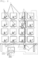
Fig. 2 eine schematische Darstellung eines Abfüllautomaten, -
Fig. 3 eine Ansicht eines Abfüllautomaten von vorn ohne Gehäuse mit Transportvorrichtung und Vorratsbehältern mit Gewindespindelstellantrieben, -
Fig. 4 eine räumliche Ansicht eines Abfüllautomaten ohne Gehäuse mit Transportvorrichtung und unterschiedlich großen Vorratsbehältern und Zahnriemenstellantrieben, -
Fig. 5 eine seitliche Ansicht eines Abfüllautomaten ohne Gehäuse mit Transportvorrichtung und Vorratsbehältern und Zahnriemenstellantrieben, -
Fig. 6 bis 8 perspektivische Detaildarstellungen eines Vorratsbehälters in einer Vorratsbehälteraufnahme mit vertikalem Bewegungselement, Aufnahmeeinheit und Transportbehälter, -
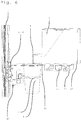
Fig. 9 eine perspektivische Detaildarstellung einer Transportvorrichtung mit Aufnahmeeinheit, Wägeeinrichtung und Betätigungsvorrichtung, -
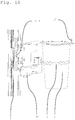
Fig. 10 eine perspektivische Detaildarstellung einer Transportvorrichtung mit Transportbehälter, Aufnahmeeinheit, Wägeeinrichtung und Betätigungsvorrichtung, -
Fig.11 eine perspektivische Detaildarstellung von oben von einer Transportvorrichtung mit Transportbehälter und Betätigungsvorrichtung sowie mit den Gewindespindelstellantrieben, -
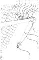
Fig. 12 eine perspektivische Detaildarstellung mit horizontalem und vertikalen Stellantrieben als Zahnriemenantrieb und mit Positionierungseinrichtung und -
Fig. 13 eine perspektivische Detaildarstellung mit horizontalem und vertikalen Stellantrieben als Gewindespindelantrieb und mit Transportbehälter, Aufnahmeeinheit und Positionierungseinrichtung.
-
Fig. 1 an exterior view of a bottling machine -
Fig. 2 a schematic representation of a bottling machine, -
Fig. 3 a view of a bottling machine from the front without housing with transport device and reservoirs with threaded spindle actuators, -
Fig. 4 a spatial view of a filling machine without housing with transport device and different sized reservoirs and timing belt actuators, -
Fig. 5 a side view of a filling machine without housing with transport device and reservoirs and timing belt actuators, -
Fig. 6 to 8 detailed perspective views of a storage container in a storage container receptacle with vertical movement element, receiving unit and transport container, -
Fig. 9 a detailed perspective view of a transport device with receiving unit, weighing device and actuator, -
Fig. 10 a detailed perspective view of a transport device with transport container, receiving unit, weighing device and actuator, -
Figure 11 a detailed perspective view of a transport device with transport container and actuator and with the threaded spindle actuators, -
Fig. 12 a detailed perspective view with horizontal and vertical actuators as a toothed belt drive and with positioning device and -
Fig. 13 a detailed perspective view with horizontal and vertical actuators as threaded spindle drive and with transport container, receiving unit and positioning device.
In
Der in
Die Transportvorrichtung 3 besitzt, wie in den
Die Bewegungselemente 8, 9 sind, wie in den
Die vertikale Bewegung ist, wie in den
Zusätzlich ist, wie in den
Eine passive Betätigungsvorrichtungen 17 kann, wie in den
Eine weitere zweckmäßige Ausführung ist eine Entleerungshilfsvorrichtung 10, die beispielsweise auf schlauchartige Vorratsbehälter 1 mit pastösem Inhalt, wie Honig bzw. Marmelade einen Druck ausübt, um die Entnahme der Waren zu ermöglichen. Weiterhin ist es vorgesehen, dass der Vorratsbehälter 1 oder die Vorratsbehälteraufnahme zum Entleeren angekippt wird. Als Entleerungshilfsvorrichtung 10 kommt ein Hebel in Betracht, welcher ein Kippen der Vorratsbehälteraufnahme 28 oder des Vorratsbehälter 1 bewirkt und somit den Vorschub der Ware aus dem Vorratsbehälter in die Endverpackung vereinfacht oder gegebenenfalls ermöglicht. Auch Vorrichtungen, welche die Vorratsbehälter 1 in Schwingungen oder Vibrationen versetzen, unterstützen die Entleerung. Solche Vibrationselemente 10 sind, wie in den
Die Vorratsbehälter 1 sind, wie in der
Die Auslassöffnungen 4 können, wie in
Die Transportbehälter 2 sind als Endverpackung oder Mitnamebehälter für den Kunden vorgesehen. Dazu werden die Transportbehälter 2 durch eine Etikettiervorrichtung 20 mit einem Etikett versehen, das die Inhaltsangabe mit Mengen und Preis sowie Haltbarkeit beinhalten kann. Die Daten werden im Zusammenwirken mit der Steuereinheit 12 und dem Datenspeicher 15 übernommen. Eine zweckmäßige Ausführung umfasst eine Bezahleinrichtung 21, die mit der Steuereinheit 12 und dem Datenspeicher 15 zusammenwirkt und einen autarken Betrieb als Selbstbedienungsautomat ermöglicht. Die Bezahleinrichtung 21 kann dabei für eine Bezahlung mit Bargeld und/oder bargeldlos ausgeführt sein.The
Der Inhalt der Transportbehälter 2 ist bei Bedarf mit einer an der Aufnahmeeinheit 5 angeordneten Mischvorrichtung mischbar. Die Mischvorrichtung können Schüttelvorrichtungen bzw. Rüttelvorrichtungen sein, welche von außen auf den Transportbehälter wirken und somit die einzelnen Waren bzw. Zutaten im Transportbehälter bzw. Becher vermischt. Eine Mischvorrichtung als Rührvorrichtung, beispielsweise in Form eines Kunststofflöffels, ist ebenso denkbar, würde jedoch mit dem Transportbehälter ausgegeben werden, da an dieser eine Verunreinigung zurückbliebe, welche aus hygienischer Sicht nicht gewollt ist.If necessary, the contents of the
Die Vorratsbehältern 1 können, wie in
Im Gehäuses 26 befindet sich, wie in den
Bei einer weiteren, nicht dargestellten Ausführung sind die Vibrationselemente 10 als Unwuchtmotoren direkt an den Vorratsbehälteraufnahmen 28 angeordnet. Die Vibrationselemente 10 lassen sich je nach Bedarf kontinuierlich oder gepulst betreiben bzw. ansteuern. Bei mehr als ein Vibrationselement 10 lassen sich diese gleichzeitig oder sequenziell oder in Gruppen ansteuern, um die Warenausgabe zu begünstigen und eventuelle Verstopfungen durch Brückenbildungen aufzulösen.In another embodiment, not shown, the
Die
Die
Die Bewegung des Transportbehälters 2 erfolgt durch das vertikale Bewegungselement 8 entlang der zugeordneten Gewindestange des Stellantriebs 7 in vertikaler Richtung. Die horizontale Bewegung wird durch das horizontale Bewegungselement 9 entlang der horizontalen Gewindestange 7 realisiert. Vorgesehen für die vertikalen und horizontalen Stellantriebe 7 sind ebenfalls lineare Direktantriebe, Linearmotoren sowie Riemenantriebe. Damit ist letztlich jeder Punkt der Matrix erreichbar. Somit sind auch Vorratsbehälter 1 unterschiedlicher Höhen und Breiten verwendbar, wobei die Transportvorrichtung 3 mit dem Transportbehälter 2 unter die entsprechenden Auslassöffnungen 4 der Vorratsbehälter 1 bewegt wird.The movement of the
Das Verfahren zur Nutzung des Abfüllautomaten 26 für flüssige und schüttbare Waren umfasst die Schritte:
- A) Auswahl der gewünschten Ware oder Waren mittels einer Eingabeeinheit 16 durch den Benutzer,
- B) Übermittlung der Auswahl an
eine Steuereinheit 12, - C) Ansteuerung einer der Transportvorrichtung 3
für den Transportbehälter 2 durch dieSteuereinheit 12, - D) Bewegung des
Transportbehälters 2 zu einem und ggf.weiteren Vorratsbehältern 1, - E) Abgabe der
Ware vom Vorratsbehälter 1 inden Transportbehälter 2 durch Ansteuerung der Auslassöffnung 4 und - F) Bewegung des
Transportbehälters 2 mittels der Steuereinheit 12 und der Transportvorrichtung 3 zu einer Entnahmeöffnung 6 zwecks Übergabe an den Benutzer.
- A) selection of the desired goods or goods by means of an
input unit 16 by the user, - B) transmission of the selection to a
control unit 12, - C) control of the transport device 3 for the
transport container 2 by thecontrol unit 12, - D) movement of the
transport container 2 to one and possiblyfurther storage containers 1, - E) delivery of the goods from the
storage container 1 in thetransport container 2 by controlling theoutlet opening 4 and - F) Movement of the
transport container 2 by means of thecontrol unit 12 and the transport device 3 to aremoval opening 6 for the purpose of transfer to the user.
Je nach Auswahl der Waren und der jeweiligen Menge und Zusammensetzung der Waren im Transportbehälter 2 wiederholen sich die Verfahrensschritte D und E.Depending on the selection of the goods and the respective quantity and composition of the goods in the
Weitere zweckmäßige Verfahrensschritte sind
- G) die
Entnahme eines Transportbehälters 2 aus einem Depot von Transportbehältern (vor D) H) Abwicklung der Bezahlung über eine Bezahleinrichtung 21 (nach A) - I) Ausdruck und ggf. Anbringen eines
Etiketts am Transportbehälter 2, Deckel, Schraubverschluss und/oder an der Folie mittels einer Etikettiervorrichtung 20 (nach A) - J) Mischen der
Waren im Transportbehälter 2 durch eine Mischvorrichtung (nach E) - K) Wägen des Inhalts des Transportbehälters 2 (parallel zu E),
- L) Einlegen zumindest einer weiteren separat verpackten Ware, vor dem Verschließen des Transportbehälters 2 (also vor F oder vor M) und
- M) Verschließen des
Transportbehälters 2 mit Deckel, einen Schraubverschluss und/oder einer Folie (vor F).
- G) the removal of a
transport container 2 from a depot of transport containers (before D) H) processing of the payment via a payment device 21 (according to A) - I) Printing out and optionally attaching a label to the
transport container 2, cover, screw cap and / or to the film by means of a labeling device 20 (according to A) - J) mixing the goods in the
transport container 2 by a mixing device (according to E) - K) weighing the contents of the transport container 2 (parallel to E),
- L) inserting at least one further separately packaged product, before closing the transport container 2 (ie before F or before M) and
- M) Closing the
transport container 2 with lid, a screw cap and / or a film (before F).
Als virtuelles Shopsystem kann auch mit Hilfe einer Software oder Homepage für beliebige PCs oder Smartphones eine Bedienoberfläche zur Verfügung gestellt werden, so dass der Konsument auch die Möglichkeit hat, sich seine individuelle Zusammenstellung unabhängig vom Eingabemodul des Automaten auswählen zu können. Das virtuelle Shopsystem reflektiert hierbei den Bestand der Waren die sich in dem Automaten in den Vorratsbehältern befinden. Die kommunikative Verbindung zwischen dem Abfüllautomaten 26 und des virtuellen Shops kann neben einer Datenverbindung über das Internet auch mit Hilfe des Lesens von Codes von einem Ausdruck oder von einem Smartphone-Display oder ähnlichem erfolgen. Hierfür ist der Automat mit einem Internetzugang und/oder einem Code-Scanner ausgestattet.As a virtual shop system, a user interface can also be made available for any PCs or smartphones with the aid of a software or homepage, so that the consumer also has the option of being able to select his individual composition independently of the input module of the machine. The virtual shop system reflects the inventory of goods that are in the vending machine in the storage containers. The communicative connection between the bottling
Die Waren sind Lebensmittel oder Tiernahrungsprodukte, evtl. auch Non-Food-Artikel. Ein Beispiel von schüttbaren Waren für Lebensmittel ist Müsli mit Müslikomponenten, wie Cerealien und gefriergetrockneten Früchten. Weitere Beispiele sind Süßigkeiten für eine einzelne Ausgabe oder als individuelle Süßigkeitenmischung, Kaffeebohnen für eine einzelne Ausgabe oder als individuelle Mischung, Zutaten für unterschiedlichen Backmischungen sowie Gewürze für eine einzelne Ausgabe oder als Gewürzmischungen. Beispiele von flüssigen Waren für Lebensmittel sind Säfte für eine einzelne Ausgabe oder als Saftmischungen und Cocktails. Beispiele von schüttbaren Waren für Tiernahrung sind Hundefutter, Katzenfutter und Vogelfutter. Als Non-Food Artikel kommen als schüttbare Waren beispielsweise Schrauben, Unterlegscheiben und Muttern in Betracht.The goods are food or pet food products, possibly also non-food items. An example of bulk food products is muesli with cereal components such as cereals and lyophilized fruits. Other examples are candy for a single dispensing or as an individual confectionery mix, coffee beans for a single dispensing or individual blending, ingredients for different blended blends, and single issue or spice blends. Examples of liquid food products are juices for a single issue or as juice blends and cocktails. Examples of pourable goods for pet food are dog food, cat food and bird food. As non-food items come as pourable goods such as screws, washers and nuts into consideration.
- 1 -1 -
- Vorratsbehälterreservoir
- 2 -2 -
- Transportbehältertransport container
- 3 -3 -
- Transportvorrichtungtransport device
- 4 -4 -
- Auslassöffnungoutlet
- 5 -5 -
- Aufnahmeeinheitrecording unit
- 6 -6 -
- Entnahmeöffnungremoval opening
- 7 -7 -
- Stellantriebactuator
- 8 -8th -
- Bewegungselementmover
- 9 -9 -
- Bewegungselementmover
- 10 -10 -
- Entleerungshilfsvorrichtung, VibrationselementDischarge aid, vibration element
- 12 -12 -
- Steuereinheitcontrol unit
- 13 -13 -
- Codierungenencodings
- 14 -14 -
- Lesegerätreader
- 15 -15 -
- Datenspeicherdata storage
- 16 -16 -
- Eingabeeinheit, Bedieneinheit, AnzeigeeinheitInput unit, operating unit, display unit
- 17 -17 -
- Betätigungsvorrichtungactuator
- 18 -18 -
- Dosiervorrichtungmetering
- 19 -19 -
- Wägeeinrichtungweighing
- 20 -20 -
- Etikettiervorrichtunglabeling
- 21 -21 -
- Bezahleinrichtungpaying means
- 23 -23 -
- Positionierungseinrichtungpositioning device
- 24 -24 -
- Motorantriebmotor drive
- 26 -26 -
- Gehäuse, AbfüllautomatHousing, filling machine
- 27 -27 -
- Regalbodenshelf
- 28 -28 -
- VorratsbehälteraufnahmeReservoir recording
- 29 -29 -
- Führungsschieneguide rail
Claims (7)
- Automatic filling machine (26) for a variety of different pourable foods or animal feed products as goods, where the goods are stored in several, interchangeable storage containers (1), which are arranged in shelf-type manner at least in two dimensions in that the storage containers (1) are fitted with an outlet opening (4) and arranged in a housing (26) and in that the housing (26) has a removal opening (6) and in that an input unit (16) is arranged on the filling device and where the input unit (16) is connected with a control unit (12), characterised in that,
at least one transport container (2) can be moved by a rolling/moving or sliding/moving transport device (3) due to the dimensions of the arrangement of the storage containers (1) so that the transport containers (2) can be transported to the storage containers (1) and/or their outlet openings (4) and the content of the storage containers (1) can be dispensed directly into the transport container (2), where the transport device (3) can be selected by the control unit (12) and where the transport container (2) constitutes the final packaging, where the housing (26) contains storage container retainers (28) where one, two or more storage containers (1) are each arranged in a storage container retainer (28) and the storage containers (1) and/or the storage container retainers (28) are designed to allow at least in one dimension sliding, tipping, swivelling and/or potentially vibrating, where the transport device (3) features a vibration element (10) as emptying assistance device (10) and where the vibration element (10) on the transport device (3) has immediate contact with the storage container (1) and transfers vibrations to the storage container (1), where the frequency of the vibrations transferred by the vibration element (10) of the transport device (3) and the position of the vibrations transferred by the vibration element (10) of the transport device (3) vary depending on the filling level and content of the storage containers (1). - Automatic filling machine according to claim 1,
characterised,
in that at least one positioning facility (23) for positioning of the transport container (2) relative to the storage container (1) in at least one dimension and/or at least one actuating device (17) for the outlet opening (4) is provided, where the positioning facility (23) is connected with the control unit (12) and the actuating device (17) may be connected with the control unit (12). - Automatic filling machine according to one of the claims 1 to 2,
characterised,
in that the storage container (1), the receiving unit (5) and/or storage container retainer (28) is provided with an emptying assistance device (10). - Automatic filling machine according to one of the claims 1 to 3,
characterised,
in that the storage containers (1) are equipped with codes (13) and on the receiving unit (5) or the transport device (3) a reading unit (14) for the code (13) is arranged where the information of the code (13) can be stored in a data store (15) connected with the control unit (12). - Automatic filling machine according to one of the claims 1 to 4,
characterised,
in that the outlet openings (4) are designed as metering devices (18). - Automatic filling machine according to one of the claims 1 to 5,
characterised,
in that on the storage containers (1), on the receiving unit (5) and/or the transport device (3) a weighing facility (19) is arranged, where the weighing facility (19) is connected with the control unit (12). - Automatic filling machine according to one of the claims 1 to 6,
characterised,
in that a closing device for closing the transport container, a labelling device (20) and/or payment facility (21) is provided, where the labelling device (20), the closing device and/or the payment facility (21) is connected with the control unit (12).
Applications Claiming Priority (1)
| Application Number | Priority Date | Filing Date | Title |
|---|---|---|---|
| DE102013110929 | 2013-10-01 |
Publications (2)
| Publication Number | Publication Date |
|---|---|
| EP2858043A1 EP2858043A1 (en) | 2015-04-08 |
| EP2858043B1 true EP2858043B1 (en) | 2018-01-31 |
Family
ID=51786780
Family Applications (1)
| Application Number | Title | Priority Date | Filing Date |
|---|---|---|---|
| EP14187393.5A Active EP2858043B1 (en) | 2013-10-01 | 2014-10-01 | Filling machine for liquid and pourable goods |
Country Status (3)
| Country | Link |
|---|---|
| EP (1) | EP2858043B1 (en) |
| DE (1) | DE102014114259A1 (en) |
| ES (1) | ES2667193T3 (en) |
Cited By (2)
| Publication number | Priority date | Publication date | Assignee | Title |
|---|---|---|---|---|
| CN110404468A (en) * | 2018-06-08 | 2019-11-05 | 克洛布股份公司 | The dispenser and correlation technique for preparing user-defined preparation by distributing fluid product |
| DE102021121866A1 (en) | 2021-08-24 | 2023-03-02 | Baskim Kaytas | Box module for beverage bags according to the bag-in-box system, receiving module for this and matrix arrangement of receiving modules |
Families Citing this family (8)
| Publication number | Priority date | Publication date | Assignee | Title |
|---|---|---|---|---|
| EP3239093A1 (en) * | 2016-04-25 | 2017-11-01 | Charles Seadon | Automatic beverage, drinks, and snacks dispenser |
| IT201600089191A1 (en) * | 2016-09-02 | 2018-03-02 | Velasquez Dante Daniel Cruz | MACHINE TO SUPPLY A PLURALITY OF FOOD LIQUIDS FOR THE CREATION OF A COCKTAIL |
| US10206478B1 (en) | 2018-04-18 | 2019-02-19 | CLiCS, LLC | Dye dispensing system |
| US11319151B2 (en) * | 2019-02-08 | 2022-05-03 | Abb Schweiz Ag | Automated storage and retrieval system |
| EP3722251A1 (en) * | 2019-04-12 | 2020-10-14 | Societe Anonyme des Eaux Minerales d'Evian Et en Abrege "S.A.E.M.E" | Liquid dispenser |
| US10783507B1 (en) | 2019-07-03 | 2020-09-22 | Spellbound Development Group, Inc. | Consumables dispensing system and method |
| JP7358851B2 (en) | 2019-08-30 | 2023-10-11 | 富士電機株式会社 | beverage dispensing equipment |
| CN113643474B (en) * | 2021-08-06 | 2022-08-02 | 彭敏燕 | Novel driven coin-feed vending machine and use method |
Family Cites Families (16)
| Publication number | Priority date | Publication date | Assignee | Title |
|---|---|---|---|---|
| NL7312482A (en) | 1972-09-15 | 1974-03-19 | ||
| FR2537307A1 (en) | 1982-07-02 | 1984-06-08 | Polyvend | CUP SEPARATOR MODULE AND AUTOMATIC DISPENSER EQUIPPED WITH THIS MODULE |
| US4526215A (en) * | 1983-07-14 | 1985-07-02 | Harrison William J | Apparatus for forming mixtures of fluids |
| IT1223978B (en) | 1988-12-07 | 1990-09-29 | Giuseppe Stefano Piana | PROCEDURE FOR THE PREPARATION OF A DRINK IN A DRINK DISTRIBUTOR MACHINE DISTRIBUTOR MACHINE IMPLEMENTING THE PROCEDURE AND AGITATOR DEVICE THAT CAN BE USED IN SUCH MACHINE |
| IT227060Y1 (en) * | 1992-12-15 | 1997-09-09 | Salce Elettromecc | IMPROVED VOLUMETRIC DOSER EQUIPPED WITH MOBILE PIPETTE LONG TWO DIMENSIONS OF A HOB AND MODULAR BASKETS |
| US5934344A (en) * | 1997-12-24 | 1999-08-10 | Pemla Technologies Inc. | Printing ink storage container and associated dispensing apparatus |
| IT1315218B1 (en) * | 1999-09-29 | 2003-02-03 | Ducale Macchine Da Caffe Di Sa | AUTOMATIC DISPENSER OF BEVERAGES IN GLASS AND RELATED METHOD FOR PREPARING THOSE |
| WO2004062776A1 (en) * | 2003-01-09 | 2004-07-29 | Nego 2000, S.C.L. | Machine for the preparation of creams |
| US7123989B2 (en) * | 2003-07-01 | 2006-10-17 | Asteres, Inc. | System and method for providing a random access and random load dispensing unit |
| CN101111870B (en) * | 2004-11-08 | 2013-01-09 | 朱莉·R·巴塞洛缪 | Automated customized cosmetic dispenser |
| JP2006244207A (en) * | 2005-03-04 | 2006-09-14 | Sanden Corp | Vending machine |
| DE102005044011A1 (en) | 2005-09-13 | 2007-03-22 | Satro Gmbh | Method of making a muesli preparation in a machine esp. a vending or dispensing machine |
| DE102005063197B4 (en) * | 2005-12-30 | 2008-02-07 | Gerhard Haas | Automated bearing assembly and method for storage and dispensing of drugs |
| DE102006049160B3 (en) | 2006-10-18 | 2008-02-28 | Bodensohn Präzision GmbH | Storage device for supplying articles carried in container, has support frame and linear unit, which is displaceable in direction of vertical axis inside support frame unit and arranged around the axis |
| EP2243706A1 (en) * | 2009-04-25 | 2010-10-27 | Nestec S.A. | A water fountain |
| DE102009050825A1 (en) | 2009-10-27 | 2011-04-28 | Natalie Stepanow | Automated cereal bar for retail use |
-
2014
- 2014-09-30 DE DE102014114259.4A patent/DE102014114259A1/en not_active Withdrawn
- 2014-10-01 EP EP14187393.5A patent/EP2858043B1/en active Active
- 2014-10-01 ES ES14187393.5T patent/ES2667193T3/en active Active
Non-Patent Citations (1)
| Title |
|---|
| None * |
Cited By (2)
| Publication number | Priority date | Publication date | Assignee | Title |
|---|---|---|---|---|
| CN110404468A (en) * | 2018-06-08 | 2019-11-05 | 克洛布股份公司 | The dispenser and correlation technique for preparing user-defined preparation by distributing fluid product |
| DE102021121866A1 (en) | 2021-08-24 | 2023-03-02 | Baskim Kaytas | Box module for beverage bags according to the bag-in-box system, receiving module for this and matrix arrangement of receiving modules |
Also Published As
| Publication number | Publication date |
|---|---|
| EP2858043A1 (en) | 2015-04-08 |
| ES2667193T3 (en) | 2018-05-10 |
| DE102014114259A1 (en) | 2015-04-02 |
Similar Documents
| Publication | Publication Date | Title |
|---|---|---|
| EP2858043B1 (en) | Filling machine for liquid and pourable goods | |
| DE60309723T2 (en) | METHOD, MACHINE AND PACK FOR THE MANUFACTURE AND TRANSPORT OF HOT AND COLD DRINKS | |
| DE69720939T2 (en) | Solid drug delivery device | |
| EP1622707B1 (en) | Device for dosing and mixing powdery materials | |
| EP2673197B1 (en) | Method and device for filling packages with a padding material in bulk material form | |
| WO2013057075A1 (en) | Automatic catering machine and method for operating it | |
| DE2727675A1 (en) | DEVICE FOR FILLING AND ASSEMBLING BEVERAGE PACK CUPS | |
| DE4016094A1 (en) | CUP DISPENSER FOR AN AUTOMATED BEVERAGE MAKING SYSTEM | |
| DE2036460A1 (en) | Bulk dispensing arrangement | |
| DE102014110866B4 (en) | Piece of furniture, especially a kitchenette | |
| DE102005021109A1 (en) | Final-stage packing machine has a product position sensor linked to drive unit | |
| JP2011065250A (en) | Bowl dish food vending machine | |
| EP0727078A1 (en) | Automatic terminal for distributing crates of drinks | |
| EP1617385B1 (en) | Method and system for storage, processing and dispensing of food products | |
| DE102010022799A1 (en) | Food vending machine for storing, cooling and heating food, has rotatable transportation platform e.g. round turntable, for transporting food to station in machine, and oven and/or infrared grille arranged at station | |
| DE3605921A1 (en) | Drinks vending machine | |
| EP1433381A1 (en) | Automated baking apparatus | |
| DE19940978A1 (en) | Automatic goods vending device uses robot transfer device for extracting required goods from store for transfer to delivery device | |
| WO2011050799A1 (en) | Vending and packing machine for loose foods | |
| EP3468911B1 (en) | Apparatus for the machine-controlled production of multi-component beverages | |
| EP1733654A1 (en) | Vending machine | |
| DE102022101671A1 (en) | Feeding unit, automated apparatus and method for food preparation | |
| AT524836B1 (en) | Food dispenser | |
| DE102021129540B4 (en) | Acceptance procedure for empties to be taken back and packages to be sent, package empties acceptance station and goods sales branch for this | |
| WO2020174089A1 (en) | Device and method for providing loose piece goods in separated form |
Legal Events
| Date | Code | Title | Description |
|---|---|---|---|
| PUAI | Public reference made under article 153(3) epc to a published international application that has entered the european phase |
Free format text: ORIGINAL CODE: 0009012 |
|
| 17P | Request for examination filed |
Effective date: 20141001 |
|
| AK | Designated contracting states |
Kind code of ref document: A1 Designated state(s): AL AT BE BG CH CY CZ DE DK EE ES FI FR GB GR HR HU IE IS IT LI LT LU LV MC MK MT NL NO PL PT RO RS SE SI SK SM TR |
|
| AX | Request for extension of the european patent |
Extension state: BA ME |
|
| R17P | Request for examination filed (corrected) |
Effective date: 20151006 |
|
| RBV | Designated contracting states (corrected) |
Designated state(s): AL AT BE BG CH CY CZ DE DK EE ES FI FR GB GR HR HU IE IS IT LI LT LU LV MC MK MT NL NO PL PT RO RS SE SI SK SM TR |
|
| 17Q | First examination report despatched |
Effective date: 20151124 |
|
| GRAP | Despatch of communication of intention to grant a patent |
Free format text: ORIGINAL CODE: EPIDOSNIGR1 |
|
| INTG | Intention to grant announced |
Effective date: 20170224 |
|
| GRAJ | Information related to disapproval of communication of intention to grant by the applicant or resumption of examination proceedings by the epo deleted |
Free format text: ORIGINAL CODE: EPIDOSDIGR1 |
|
| INTC | Intention to grant announced (deleted) | ||
| GRAP | Despatch of communication of intention to grant a patent |
Free format text: ORIGINAL CODE: EPIDOSNIGR1 |
|
| INTG | Intention to grant announced |
Effective date: 20170811 |
|
| GRAS | Grant fee paid |
Free format text: ORIGINAL CODE: EPIDOSNIGR3 |
|
| GRAA | (expected) grant |
Free format text: ORIGINAL CODE: 0009210 |
|
| AK | Designated contracting states |
Kind code of ref document: B1 Designated state(s): AL AT BE BG CH CY CZ DE DK EE ES FI FR GB GR HR HU IE IS IT LI LT LU LV MC MK MT NL NO PL PT RO RS SE SI SK SM TR |
|
| REG | Reference to a national code |
Ref country code: GB Ref legal event code: FG4D Free format text: NOT ENGLISH Ref country code: CH Ref legal event code: EP |
|
| REG | Reference to a national code |
Ref country code: AT Ref legal event code: REF Ref document number: 968004 Country of ref document: AT Kind code of ref document: T Effective date: 20180215 |
|
| REG | Reference to a national code |
Ref country code: IE Ref legal event code: FG4D Free format text: LANGUAGE OF EP DOCUMENT: GERMAN |
|
| REG | Reference to a national code |
Ref country code: DE Ref legal event code: R096 Ref document number: 502014007087 Country of ref document: DE |
|
| REG | Reference to a national code |
Ref country code: NL Ref legal event code: FP |
|
| REG | Reference to a national code |
Ref country code: ES Ref legal event code: FG2A Ref document number: 2667193 Country of ref document: ES Kind code of ref document: T3 Effective date: 20180510 |
|
| REG | Reference to a national code |
Ref country code: LT Ref legal event code: MG4D |
|
| PG25 | Lapsed in a contracting state [announced via postgrant information from national office to epo] |
Ref country code: NO Free format text: LAPSE BECAUSE OF FAILURE TO SUBMIT A TRANSLATION OF THE DESCRIPTION OR TO PAY THE FEE WITHIN THE PRESCRIBED TIME-LIMIT Effective date: 20180430 Ref country code: HR Free format text: LAPSE BECAUSE OF FAILURE TO SUBMIT A TRANSLATION OF THE DESCRIPTION OR TO PAY THE FEE WITHIN THE PRESCRIBED TIME-LIMIT Effective date: 20180131 Ref country code: LT Free format text: LAPSE BECAUSE OF FAILURE TO SUBMIT A TRANSLATION OF THE DESCRIPTION OR TO PAY THE FEE WITHIN THE PRESCRIBED TIME-LIMIT Effective date: 20180131 Ref country code: FI Free format text: LAPSE BECAUSE OF FAILURE TO SUBMIT A TRANSLATION OF THE DESCRIPTION OR TO PAY THE FEE WITHIN THE PRESCRIBED TIME-LIMIT Effective date: 20180131 |
|
| PG25 | Lapsed in a contracting state [announced via postgrant information from national office to epo] |
Ref country code: IS Free format text: LAPSE BECAUSE OF FAILURE TO SUBMIT A TRANSLATION OF THE DESCRIPTION OR TO PAY THE FEE WITHIN THE PRESCRIBED TIME-LIMIT Effective date: 20180531 Ref country code: BG Free format text: LAPSE BECAUSE OF FAILURE TO SUBMIT A TRANSLATION OF THE DESCRIPTION OR TO PAY THE FEE WITHIN THE PRESCRIBED TIME-LIMIT Effective date: 20180430 Ref country code: PL Free format text: LAPSE BECAUSE OF FAILURE TO SUBMIT A TRANSLATION OF THE DESCRIPTION OR TO PAY THE FEE WITHIN THE PRESCRIBED TIME-LIMIT Effective date: 20180131 Ref country code: SE Free format text: LAPSE BECAUSE OF FAILURE TO SUBMIT A TRANSLATION OF THE DESCRIPTION OR TO PAY THE FEE WITHIN THE PRESCRIBED TIME-LIMIT Effective date: 20180131 Ref country code: LV Free format text: LAPSE BECAUSE OF FAILURE TO SUBMIT A TRANSLATION OF THE DESCRIPTION OR TO PAY THE FEE WITHIN THE PRESCRIBED TIME-LIMIT Effective date: 20180131 Ref country code: RS Free format text: LAPSE BECAUSE OF FAILURE TO SUBMIT A TRANSLATION OF THE DESCRIPTION OR TO PAY THE FEE WITHIN THE PRESCRIBED TIME-LIMIT Effective date: 20180131 Ref country code: GR Free format text: LAPSE BECAUSE OF FAILURE TO SUBMIT A TRANSLATION OF THE DESCRIPTION OR TO PAY THE FEE WITHIN THE PRESCRIBED TIME-LIMIT Effective date: 20180501 |
|
| PG25 | Lapsed in a contracting state [announced via postgrant information from national office to epo] |
Ref country code: MT Free format text: LAPSE BECAUSE OF FAILURE TO SUBMIT A TRANSLATION OF THE DESCRIPTION OR TO PAY THE FEE WITHIN THE PRESCRIBED TIME-LIMIT Effective date: 20180131 |
|
| REG | Reference to a national code |
Ref country code: FR Ref legal event code: PLFP Year of fee payment: 5 |
|
| PG25 | Lapsed in a contracting state [announced via postgrant information from national office to epo] |
Ref country code: EE Free format text: LAPSE BECAUSE OF FAILURE TO SUBMIT A TRANSLATION OF THE DESCRIPTION OR TO PAY THE FEE WITHIN THE PRESCRIBED TIME-LIMIT Effective date: 20180131 Ref country code: AL Free format text: LAPSE BECAUSE OF FAILURE TO SUBMIT A TRANSLATION OF THE DESCRIPTION OR TO PAY THE FEE WITHIN THE PRESCRIBED TIME-LIMIT Effective date: 20180131 Ref country code: RO Free format text: LAPSE BECAUSE OF FAILURE TO SUBMIT A TRANSLATION OF THE DESCRIPTION OR TO PAY THE FEE WITHIN THE PRESCRIBED TIME-LIMIT Effective date: 20180131 |
|
| REG | Reference to a national code |
Ref country code: DE Ref legal event code: R097 Ref document number: 502014007087 Country of ref document: DE |
|
| PG25 | Lapsed in a contracting state [announced via postgrant information from national office to epo] |
Ref country code: CZ Free format text: LAPSE BECAUSE OF FAILURE TO SUBMIT A TRANSLATION OF THE DESCRIPTION OR TO PAY THE FEE WITHIN THE PRESCRIBED TIME-LIMIT Effective date: 20180131 Ref country code: SK Free format text: LAPSE BECAUSE OF FAILURE TO SUBMIT A TRANSLATION OF THE DESCRIPTION OR TO PAY THE FEE WITHIN THE PRESCRIBED TIME-LIMIT Effective date: 20180131 Ref country code: SM Free format text: LAPSE BECAUSE OF FAILURE TO SUBMIT A TRANSLATION OF THE DESCRIPTION OR TO PAY THE FEE WITHIN THE PRESCRIBED TIME-LIMIT Effective date: 20180131 Ref country code: DK Free format text: LAPSE BECAUSE OF FAILURE TO SUBMIT A TRANSLATION OF THE DESCRIPTION OR TO PAY THE FEE WITHIN THE PRESCRIBED TIME-LIMIT Effective date: 20180131 |
|
| PLBE | No opposition filed within time limit |
Free format text: ORIGINAL CODE: 0009261 |
|
| STAA | Information on the status of an ep patent application or granted ep patent |
Free format text: STATUS: NO OPPOSITION FILED WITHIN TIME LIMIT |
|
| 26N | No opposition filed |
Effective date: 20181102 |
|
| PG25 | Lapsed in a contracting state [announced via postgrant information from national office to epo] |
Ref country code: SI Free format text: LAPSE BECAUSE OF FAILURE TO SUBMIT A TRANSLATION OF THE DESCRIPTION OR TO PAY THE FEE WITHIN THE PRESCRIBED TIME-LIMIT Effective date: 20180131 |
|
| REG | Reference to a national code |
Ref country code: CH Ref legal event code: PL |
|
| GBPC | Gb: european patent ceased through non-payment of renewal fee |
Effective date: 20181001 |
|
| REG | Reference to a national code |
Ref country code: BE Ref legal event code: MM Effective date: 20181031 |
|
| PG25 | Lapsed in a contracting state [announced via postgrant information from national office to epo] |
Ref country code: MC Free format text: LAPSE BECAUSE OF FAILURE TO SUBMIT A TRANSLATION OF THE DESCRIPTION OR TO PAY THE FEE WITHIN THE PRESCRIBED TIME-LIMIT Effective date: 20180131 Ref country code: LU Free format text: LAPSE BECAUSE OF NON-PAYMENT OF DUE FEES Effective date: 20181001 |
|
| REG | Reference to a national code |
Ref country code: IE Ref legal event code: MM4A |
|
| PG25 | Lapsed in a contracting state [announced via postgrant information from national office to epo] |
Ref country code: CH Free format text: LAPSE BECAUSE OF NON-PAYMENT OF DUE FEES Effective date: 20181031 Ref country code: LI Free format text: LAPSE BECAUSE OF NON-PAYMENT OF DUE FEES Effective date: 20181031 Ref country code: BE Free format text: LAPSE BECAUSE OF NON-PAYMENT OF DUE FEES Effective date: 20181031 |
|
| PG25 | Lapsed in a contracting state [announced via postgrant information from national office to epo] |
Ref country code: IE Free format text: LAPSE BECAUSE OF NON-PAYMENT OF DUE FEES Effective date: 20181001 Ref country code: GB Free format text: LAPSE BECAUSE OF NON-PAYMENT OF DUE FEES Effective date: 20181001 |
|
| PG25 | Lapsed in a contracting state [announced via postgrant information from national office to epo] |
Ref country code: TR Free format text: LAPSE BECAUSE OF FAILURE TO SUBMIT A TRANSLATION OF THE DESCRIPTION OR TO PAY THE FEE WITHIN THE PRESCRIBED TIME-LIMIT Effective date: 20180131 |
|
| PG25 | Lapsed in a contracting state [announced via postgrant information from national office to epo] |
Ref country code: PT Free format text: LAPSE BECAUSE OF FAILURE TO SUBMIT A TRANSLATION OF THE DESCRIPTION OR TO PAY THE FEE WITHIN THE PRESCRIBED TIME-LIMIT Effective date: 20180131 Ref country code: HU Free format text: LAPSE BECAUSE OF FAILURE TO SUBMIT A TRANSLATION OF THE DESCRIPTION OR TO PAY THE FEE WITHIN THE PRESCRIBED TIME-LIMIT; INVALID AB INITIO Effective date: 20141001 |
|
| PG25 | Lapsed in a contracting state [announced via postgrant information from national office to epo] |
Ref country code: CY Free format text: LAPSE BECAUSE OF FAILURE TO SUBMIT A TRANSLATION OF THE DESCRIPTION OR TO PAY THE FEE WITHIN THE PRESCRIBED TIME-LIMIT Effective date: 20180131 Ref country code: MK Free format text: LAPSE BECAUSE OF NON-PAYMENT OF DUE FEES Effective date: 20180131 |
|
| PGFP | Annual fee paid to national office [announced via postgrant information from national office to epo] |
Ref country code: NL Payment date: 20231023 Year of fee payment: 10 |
|
| PGFP | Annual fee paid to national office [announced via postgrant information from national office to epo] |
Ref country code: ES Payment date: 20231117 Year of fee payment: 10 |
|
| PGFP | Annual fee paid to national office [announced via postgrant information from national office to epo] |
Ref country code: IT Payment date: 20231031 Year of fee payment: 10 Ref country code: FR Payment date: 20231023 Year of fee payment: 10 Ref country code: DE Payment date: 20231130 Year of fee payment: 10 Ref country code: AT Payment date: 20231019 Year of fee payment: 10 |