EP2857641A1 - Gas turbine engine system equipped with rankine cycle engine - Google Patents
Gas turbine engine system equipped with rankine cycle engine Download PDFInfo
- Publication number
- EP2857641A1 EP2857641A1 EP13772193.2A EP13772193A EP2857641A1 EP 2857641 A1 EP2857641 A1 EP 2857641A1 EP 13772193 A EP13772193 A EP 13772193A EP 2857641 A1 EP2857641 A1 EP 2857641A1
- Authority
- EP
- European Patent Office
- Prior art keywords
- working medium
- gas turbine
- compressor
- turbine engine
- intermediate cooler
- Prior art date
- Legal status (The legal status is an assumption and is not a legal conclusion. Google has not performed a legal analysis and makes no representation as to the accuracy of the status listed.)
- Granted
Links
Images


Classifications
-
- F—MECHANICAL ENGINEERING; LIGHTING; HEATING; WEAPONS; BLASTING
- F01—MACHINES OR ENGINES IN GENERAL; ENGINE PLANTS IN GENERAL; STEAM ENGINES
- F01K—STEAM ENGINE PLANTS; STEAM ACCUMULATORS; ENGINE PLANTS NOT OTHERWISE PROVIDED FOR; ENGINES USING SPECIAL WORKING FLUIDS OR CYCLES
- F01K23/00—Plants characterised by more than one engine delivering power external to the plant, the engines being driven by different fluids
- F01K23/02—Plants characterised by more than one engine delivering power external to the plant, the engines being driven by different fluids the engine cycles being thermally coupled
- F01K23/06—Plants characterised by more than one engine delivering power external to the plant, the engines being driven by different fluids the engine cycles being thermally coupled combustion heat from one cycle heating the fluid in another cycle
- F01K23/10—Plants characterised by more than one engine delivering power external to the plant, the engines being driven by different fluids the engine cycles being thermally coupled combustion heat from one cycle heating the fluid in another cycle with exhaust fluid of one cycle heating the fluid in another cycle
-
- F—MECHANICAL ENGINEERING; LIGHTING; HEATING; WEAPONS; BLASTING
- F01—MACHINES OR ENGINES IN GENERAL; ENGINE PLANTS IN GENERAL; STEAM ENGINES
- F01K—STEAM ENGINE PLANTS; STEAM ACCUMULATORS; ENGINE PLANTS NOT OTHERWISE PROVIDED FOR; ENGINES USING SPECIAL WORKING FLUIDS OR CYCLES
- F01K25/00—Plants or engines characterised by use of special working fluids, not otherwise provided for; Plants operating in closed cycles and not otherwise provided for
- F01K25/08—Plants or engines characterised by use of special working fluids, not otherwise provided for; Plants operating in closed cycles and not otherwise provided for using special vapours
-
- F—MECHANICAL ENGINEERING; LIGHTING; HEATING; WEAPONS; BLASTING
- F02—COMBUSTION ENGINES; HOT-GAS OR COMBUSTION-PRODUCT ENGINE PLANTS
- F02C—GAS-TURBINE PLANTS; AIR INTAKES FOR JET-PROPULSION PLANTS; CONTROLLING FUEL SUPPLY IN AIR-BREATHING JET-PROPULSION PLANTS
- F02C1/00—Gas-turbine plants characterised by the use of hot gases or unheated pressurised gases, as the working fluid
- F02C1/04—Gas-turbine plants characterised by the use of hot gases or unheated pressurised gases, as the working fluid the working fluid being heated indirectly
- F02C1/05—Gas-turbine plants characterised by the use of hot gases or unheated pressurised gases, as the working fluid the working fluid being heated indirectly characterised by the type or source of heat, e.g. using nuclear or solar energy
-
- F—MECHANICAL ENGINEERING; LIGHTING; HEATING; WEAPONS; BLASTING
- F02—COMBUSTION ENGINES; HOT-GAS OR COMBUSTION-PRODUCT ENGINE PLANTS
- F02C—GAS-TURBINE PLANTS; AIR INTAKES FOR JET-PROPULSION PLANTS; CONTROLLING FUEL SUPPLY IN AIR-BREATHING JET-PROPULSION PLANTS
- F02C6/00—Plural gas-turbine plants; Combinations of gas-turbine plants with other apparatus; Adaptations of gas- turbine plants for special use
- F02C6/18—Plural gas-turbine plants; Combinations of gas-turbine plants with other apparatus; Adaptations of gas- turbine plants for special use using the waste heat of gas-turbine plants outside the plants themselves, e.g. gas-turbine power heat plants
-
- F—MECHANICAL ENGINEERING; LIGHTING; HEATING; WEAPONS; BLASTING
- F02—COMBUSTION ENGINES; HOT-GAS OR COMBUSTION-PRODUCT ENGINE PLANTS
- F02C—GAS-TURBINE PLANTS; AIR INTAKES FOR JET-PROPULSION PLANTS; CONTROLLING FUEL SUPPLY IN AIR-BREATHING JET-PROPULSION PLANTS
- F02C7/00—Features, components parts, details or accessories, not provided for in, or of interest apart form groups F02C1/00 - F02C6/00; Air intakes for jet-propulsion plants
- F02C7/08—Heating air supply before combustion, e.g. by exhaust gases
-
- F—MECHANICAL ENGINEERING; LIGHTING; HEATING; WEAPONS; BLASTING
- F02—COMBUSTION ENGINES; HOT-GAS OR COMBUSTION-PRODUCT ENGINE PLANTS
- F02C—GAS-TURBINE PLANTS; AIR INTAKES FOR JET-PROPULSION PLANTS; CONTROLLING FUEL SUPPLY IN AIR-BREATHING JET-PROPULSION PLANTS
- F02C7/00—Features, components parts, details or accessories, not provided for in, or of interest apart form groups F02C1/00 - F02C6/00; Air intakes for jet-propulsion plants
- F02C7/12—Cooling of plants
- F02C7/14—Cooling of plants of fluids in the plant, e.g. lubricant or fuel
- F02C7/141—Cooling of plants of fluids in the plant, e.g. lubricant or fuel of working fluid
- F02C7/143—Cooling of plants of fluids in the plant, e.g. lubricant or fuel of working fluid before or between the compressor stages
-
- F—MECHANICAL ENGINEERING; LIGHTING; HEATING; WEAPONS; BLASTING
- F03—MACHINES OR ENGINES FOR LIQUIDS; WIND, SPRING, OR WEIGHT MOTORS; PRODUCING MECHANICAL POWER OR A REACTIVE PROPULSIVE THRUST, NOT OTHERWISE PROVIDED FOR
- F03G—SPRING, WEIGHT, INERTIA OR LIKE MOTORS; MECHANICAL-POWER PRODUCING DEVICES OR MECHANISMS, NOT OTHERWISE PROVIDED FOR OR USING ENERGY SOURCES NOT OTHERWISE PROVIDED FOR
- F03G6/00—Devices for producing mechanical power from solar energy
- F03G6/003—Devices for producing mechanical power from solar energy having a Rankine cycle
- F03G6/005—Binary cycle plants where the fluid from the solar collector heats the working fluid via a heat exchanger
-
- F—MECHANICAL ENGINEERING; LIGHTING; HEATING; WEAPONS; BLASTING
- F03—MACHINES OR ENGINES FOR LIQUIDS; WIND, SPRING, OR WEIGHT MOTORS; PRODUCING MECHANICAL POWER OR A REACTIVE PROPULSIVE THRUST, NOT OTHERWISE PROVIDED FOR
- F03G—SPRING, WEIGHT, INERTIA OR LIKE MOTORS; MECHANICAL-POWER PRODUCING DEVICES OR MECHANISMS, NOT OTHERWISE PROVIDED FOR OR USING ENERGY SOURCES NOT OTHERWISE PROVIDED FOR
- F03G6/00—Devices for producing mechanical power from solar energy
- F03G6/06—Devices for producing mechanical power from solar energy with solar energy concentrating means
- F03G6/064—Devices for producing mechanical power from solar energy with solar energy concentrating means having a gas turbine cycle, i.e. compressor and gas turbine combination
-
- F—MECHANICAL ENGINEERING; LIGHTING; HEATING; WEAPONS; BLASTING
- F03—MACHINES OR ENGINES FOR LIQUIDS; WIND, SPRING, OR WEIGHT MOTORS; PRODUCING MECHANICAL POWER OR A REACTIVE PROPULSIVE THRUST, NOT OTHERWISE PROVIDED FOR
- F03G—SPRING, WEIGHT, INERTIA OR LIKE MOTORS; MECHANICAL-POWER PRODUCING DEVICES OR MECHANISMS, NOT OTHERWISE PROVIDED FOR OR USING ENERGY SOURCES NOT OTHERWISE PROVIDED FOR
- F03G6/00—Devices for producing mechanical power from solar energy
- F03G6/06—Devices for producing mechanical power from solar energy with solar energy concentrating means
- F03G6/065—Devices for producing mechanical power from solar energy with solar energy concentrating means having a Rankine cycle
- F03G6/067—Binary cycle plants where the fluid from the solar collector heats the working fluid via a heat exchanger
-
- Y—GENERAL TAGGING OF NEW TECHNOLOGICAL DEVELOPMENTS; GENERAL TAGGING OF CROSS-SECTIONAL TECHNOLOGIES SPANNING OVER SEVERAL SECTIONS OF THE IPC; TECHNICAL SUBJECTS COVERED BY FORMER USPC CROSS-REFERENCE ART COLLECTIONS [XRACs] AND DIGESTS
- Y02—TECHNOLOGIES OR APPLICATIONS FOR MITIGATION OR ADAPTATION AGAINST CLIMATE CHANGE
- Y02E—REDUCTION OF GREENHOUSE GAS [GHG] EMISSIONS, RELATED TO ENERGY GENERATION, TRANSMISSION OR DISTRIBUTION
- Y02E10/00—Energy generation through renewable energy sources
- Y02E10/40—Solar thermal energy, e.g. solar towers
- Y02E10/46—Conversion of thermal power into mechanical power, e.g. Rankine, Stirling or solar thermal engines
-
- Y—GENERAL TAGGING OF NEW TECHNOLOGICAL DEVELOPMENTS; GENERAL TAGGING OF CROSS-SECTIONAL TECHNOLOGIES SPANNING OVER SEVERAL SECTIONS OF THE IPC; TECHNICAL SUBJECTS COVERED BY FORMER USPC CROSS-REFERENCE ART COLLECTIONS [XRACs] AND DIGESTS
- Y02—TECHNOLOGIES OR APPLICATIONS FOR MITIGATION OR ADAPTATION AGAINST CLIMATE CHANGE
- Y02E—REDUCTION OF GREENHOUSE GAS [GHG] EMISSIONS, RELATED TO ENERGY GENERATION, TRANSMISSION OR DISTRIBUTION
- Y02E20/00—Combustion technologies with mitigation potential
- Y02E20/14—Combined heat and power generation [CHP]
-
- Y—GENERAL TAGGING OF NEW TECHNOLOGICAL DEVELOPMENTS; GENERAL TAGGING OF CROSS-SECTIONAL TECHNOLOGIES SPANNING OVER SEVERAL SECTIONS OF THE IPC; TECHNICAL SUBJECTS COVERED BY FORMER USPC CROSS-REFERENCE ART COLLECTIONS [XRACs] AND DIGESTS
- Y02—TECHNOLOGIES OR APPLICATIONS FOR MITIGATION OR ADAPTATION AGAINST CLIMATE CHANGE
- Y02E—REDUCTION OF GREENHOUSE GAS [GHG] EMISSIONS, RELATED TO ENERGY GENERATION, TRANSMISSION OR DISTRIBUTION
- Y02E20/00—Combustion technologies with mitigation potential
- Y02E20/16—Combined cycle power plant [CCPP], or combined cycle gas turbine [CCGT]
Definitions
- the present invention relates to a combined-type gas turbine engine system equipped with a Rankine cycle engine which is driven by using exhaust heat from a gas turbine engine.
- Patent Document 1 JP Laid-open Patent Publication No. 2007-159225
- an object of the present invention is to provide a combined-type gas turbine engine system which achieves high efficiency by very effectively utilizing exhaust heat from a gas turbine engine.
- a gas turbine engine system includes: a compressor configured to compress a first working medium; a heater configured to heat the compressed first working medium utilizing an external heat source; a turbine configured to output power from the first working medium; an intermediate cooler provided at the compressor and configured to cool the first working medium compressed by a low-pressure compression part of the compressor and then supply the first working medium to a high-pressure compression part of the compressor; an exhaust heat boiler using as a heating medium an exhaust gas discharged from the turbine; and a Rankine cycle engine using the intermediate cooler and the exhaust heat boiler as heat sources and using a cooling medium of the intermediate cooler as a second working medium.
- the second working medium may be an organic substance
- the second working medium flowing from the intermediate cooler into the exhaust heat boiler may be a superheated gas.
- a solar heater configured to heat the first working medium utilizing sunlight as a heat source may be provided.
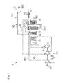
- FIG. 1 is a schematic configuration diagram showing a gas turbine engine system (hereinafter, referred to simply as "engine system") E according to an embodiment of the present invention.
- the engine system E includes a gas turbine engine unit GU and a Rankine cycle engine unit RU, and those engine units GU, RU drive respective loads such as generators GE1, GE2.
- the gas turbine engine unit GU includes a compressor 1 which compresses a first working medium M1, a combustor 3, which is a heater for heating the first working medium M1 compressed by the compressor 1, and a first turbine 5 which outputs power from the combusted first working medium M1.
- a compressor 1 which compresses a first working medium M1
- a combustor 3 which is a heater for heating the first working medium M1 compressed by the compressor 1
- a first turbine 5 which outputs power from the combusted first working medium M1.
- an air may be used as the first working medium M1.
- the compressor 1 includes a low-pressure compression part la and a high-pressure compression part 1b.
- An exhaust heat boiler 7 and an intermediate cooler 9 which cool the first working medium M1 compressed by the low-pressure compression part 1a are provided in series in this order between the low-pressure compression part 1a and the high-pressure compression part 1b.
- the exhaust heat boiler 7 will be described in detail later.
- the high-pressure first working medium M1 discharged from the compressor 1 passes through a regenerator 11 to be preheated therewith before flowing into the combustor 3, and then is sent to the combustor 3.
- the regenerator 11 is provided at an upstream portion within an exhaust duct 13 which forms a path for discharging an exhaust gas EG from the first turbine 5 to the outside, and preheats the first working medium M1 flowing from the compressor 1 toward the combustor 3 by using the heat of the high-temperature exhaust gas EG.
- the exhaust heat boiler 7 is provided on a downstream side of the regenerator 11 in the exhaust duct 13. The exhaust gas EG having passed through the regenerator 11 as a heating medium further passes through the exhaust heat boiler 7 as a heating medium and then is discharged to the outside.
- a second turbine 15 is driven by a second working medium M2 which has been heated into a gaseous state utilizing, as heat sources, the heat of the first working medium M1 passing through the intermediate cooler 9 and heat generated in the exhaust heat boiler 7.
- the second working medium M2 discharged from the second turbine 15 is condensed by a condenser 17, then passes through the intermediate cooler 9 and the exhaust heat boiler 7 again, and is supplied to the second turbine 15.
- the exhaust heat boiler 7 includes a steam generator 21 and a boiler drum 23.
- the second working medium M2 having passed through the condenser 17 ramifies to flow into the intermediate cooler 9 and an economizer 25.
- the economizer 25 is disposed at a downstream portion within the exhaust duct 13 and preheats the second working medium M2 utilizing the heat of the exhaust gas EG.
- the intermediate cooler 9 as described above, the first working medium M1 compressed by the low-pressure compression part 1a of the gas turbine unit GU acts as a medium to be cooled, namely, as a heating medium, and the second working medium M2 of the Rankine cycle engine unit RU is preheated utilizing the heat of the first working medium M1.
- the Rankine cycle engine unit RU of the present embodiment is configured as an organic Rankine cycle engine which uses an organic substance as the second working medium M2.
- a petroleum-based organic medium for example, butane or pentane, may be used.
- the second working medium M2 is a low-boiling-point organic medium, thus easily evaporates at the intermediate cooler 9, and is discharged as a superheated gas.
- the second working medium M2 preheated by the intermediate cooler 9 or the economizer 25 flows into the steam generator 21 of the exhaust heat boiler 7.
- the second working medium M2, which has become steam flows from the boiler drum 23 into a superheater 27.
- the design of the gas turbine engine unit GU is adjusted such that a pinch point which is a factor for limiting an amount of steam generated in the evaporation process of the Rankine cycle engine unit RU can be efficiently avoided, whereby it is possible to maximize the efficiency of the entire engine system E.
- a pressure ratio by the low-pressure compression part 1a is set so as to be higher than a value at which the efficiency of the gas turbine engine unit GU alone is maximized.
- the second working medium M2 when the second working medium M2 is preheated by the intermediate cooler 9 (indicated by a solid line) as shown in Fig. 3 , the quantity of flow of the first working medium M1 flowing through the intermediate cooler 9 is added to the exhaust gas EG as a heating medium, and thus an amount of change (decrease) in temperature with respect to an amount of exchanged heat at the heating medium side is decreased.
- an amount of heat exchangeable until reaching a pinch point is significantly increased, and an amount of generated steam is also increased.
- a solar heater 31 which uses sunlight SL as a heat source may be additionally provided at the upstream side of the combustor 3 as a heater which heats the first working medium M1 compressed by the compressor 1.
- the Rankine cycle engine unit RU may be configured as an ordinary steam turbine using water as the second working medium M2.
- the Rankine cycle engine unit RU is driven by using not only the exhaust heat from the first turbine 5 of the gas turbine engine unit GU but also the heat of the first working medium M1 passing through the compressor 1, and thus it is possible to obtain very high efficiency for the entire engine system E.
Abstract
Description
- This application is based on and claims Convention priority to Japanese patent application No.
2012-086211, filed April 5, 2012 - The present invention relates to a combined-type gas turbine engine system equipped with a Rankine cycle engine which is driven by using exhaust heat from a gas turbine engine.
- In recent years, as a solution to the environment problems or the energy problems, a distributed energy supply system has been proposed in which relatively small power plants are installed near electric power consumers and supply electric power. As one power source which is part of the distributed energy supply system, use of a middle-sized or small-sized gas turbine engine has been suggested (e.g., Patent Document 1). For a distributed power source, it is particularly an important issue to improve the efficiency.
- [Patent Document 1]
JP Laid-open Patent Publication No. 2007-159225 - However, as a method for improving the efficiency of a middle-sized or small-sized gas turbine, increasing of a temperature or increasing of a pressure ratio is difficult due to restrictions in size. In addition, conventionally, a regenerative cycle in which exhaust heat from a gas turbine is used for preheating a working gas is established, or a cogeneration system using exhaust heat from a gas turbine as a heat source for a steam turbine is established, thereby comprehensively improving the efficiency of the entire system. However, it is very difficult to further increase the efficiency by developing an engine with a low pressure ratio suitable for a regenerative cycle or developing a low-output and high-efficient steam turbine for use in a cogeneration system.
- Therefore, in order to solve the above-described problems, an object of the present invention is to provide a combined-type gas turbine engine system which achieves high efficiency by very effectively utilizing exhaust heat from a gas turbine engine.
- In order to achieve the above-described object, a gas turbine engine system according to the present invention includes: a compressor configured to compress a first working medium; a heater configured to heat the compressed first working medium utilizing an external heat source; a turbine configured to output power from the first working medium; an intermediate cooler provided at the compressor and configured to cool the first working medium compressed by a low-pressure compression part of the compressor and then supply the first working medium to a high-pressure compression part of the compressor; an exhaust heat boiler using as a heating medium an exhaust gas discharged from the turbine; and a Rankine cycle engine using the intermediate cooler and the exhaust heat boiler as heat sources and using a cooling medium of the intermediate cooler as a second working medium.
- With this configuration, not only the exhaust heat from the turbine of the gas turbine engine but also the heat of the working medium passing through the compressor are utilized to drive the Rankine cycle engine, and thus it is possible to obtain very high efficiency for the entire engine system.
- In one embodiment of the present invention, the second working medium may be an organic substance, and the second working medium flowing from the intermediate cooler into the exhaust heat boiler may be a superheated gas. With this configuration, by using an organic medium having a lower boiling point than that of water, it is possible to easily make the second working medium having passed through the intermediate cooler, into a superheated gas. As a result, the exhaust heat boiler serves as a superheater. Therefore, it is possible to obtain higher output than that in the case where water is used as the second working medium, and further high efficiency is obtained for the entire engine system.
- In one embodiment of the present invention, as the heater, a solar heater configured to heat the first working medium utilizing sunlight as a heat source may be provided. With this configuration, it is possible to increase the efficiency of the engine system while suppressing a load on the environment by using sunlight which is natural energy.
- Any combination of at least two constructions, disclosed in the appended claims and/or the specification and/or the accompanying drawings should be construed as included within the scope of the present invention. In particular, any combination of two or more of the appended claims should be equally construed as included within the scope of the present invention.
- In any event, the present invention will become more clearly understood from the following description of embodiments thereof, when taken in conjunction with the accompanying drawings. However, the embodiments and the drawings are given only for the purpose of illustration and explanation, and are not to be taken as limiting the scope of the present invention in any way whatsoever, which scope is to be determined by the appended claims. In the accompanying drawings, like reference numerals are used to denote like parts throughout the several views, and:
-
Fig. 1 is a block diagram showing a schematic configuration of a gas turbine engine system according to an embodiment of the present invention; -
Fig. 2 is a graph for explaining a configuration concept of the gas turbine engine system inFig. 1 ; -
Fig. 3 is a graph for explaining an advantageous effect of the gas turbine engine system inFig. 1 ; and -
Fig. 4 is a block diagram showing a modification of the gas turbine engine system inFig. 1 . - Hereinafter, embodiments of the present invention will be described with reference to the drawings.
Fig. 1 is a schematic configuration diagram showing a gas turbine engine system (hereinafter, referred to simply as "engine system") E according to an embodiment of the present invention. The engine system E includes a gas turbine engine unit GU and a Rankine cycle engine unit RU, and those engine units GU, RU drive respective loads such as generators GE1, GE2. - The gas turbine engine unit GU includes a
compressor 1 which compresses a first working medium M1, a combustor 3, which is a heater for heating the first working medium M1 compressed by thecompressor 1, and afirst turbine 5 which outputs power from the combusted first working medium M1. In the present embodiment, an air may be used as the first working medium M1. - The
compressor 1 includes a low-pressure compression part la and a high-pressure compression part 1b. Anexhaust heat boiler 7 and anintermediate cooler 9 which cool the first working medium M1 compressed by the low-pressure compression part 1a are provided in series in this order between the low-pressure compression part 1a and the high-pressure compression part 1b. Theexhaust heat boiler 7 will be described in detail later. By cooling the first working medium M1 compressed by the low-pressure compression part 1a utilizing theexhaust heat boiler 7 and theintermediate cooler 9, compression work to be done by the high-pressure compression part 1b is reduced, and therefore the efficiency is improved. The first working medium M1 flowing from the low-pressure compression part 1a toward the high-pressure compression part 1b may not be passed through theexhaust heat boiler 7 and may be cooled only by theintermediate cooler 9. - The high-pressure first working medium M1 discharged from the
compressor 1 passes through aregenerator 11 to be preheated therewith before flowing into the combustor 3, and then is sent to the combustor 3. Theregenerator 11 is provided at an upstream portion within anexhaust duct 13 which forms a path for discharging an exhaust gas EG from thefirst turbine 5 to the outside, and preheats the first working medium M1 flowing from thecompressor 1 toward the combustor 3 by using the heat of the high-temperature exhaust gas EG. Theexhaust heat boiler 7 is provided on a downstream side of theregenerator 11 in theexhaust duct 13. The exhaust gas EG having passed through theregenerator 11 as a heating medium further passes through theexhaust heat boiler 7 as a heating medium and then is discharged to the outside. - In the Rankine cycle engine unit RU, a
second turbine 15 is driven by a second working medium M2 which has been heated into a gaseous state utilizing, as heat sources, the heat of the first working medium M1 passing through theintermediate cooler 9 and heat generated in theexhaust heat boiler 7. The second working medium M2 discharged from thesecond turbine 15 is condensed by acondenser 17, then passes through theintermediate cooler 9 and theexhaust heat boiler 7 again, and is supplied to thesecond turbine 15. - The
exhaust heat boiler 7 includes asteam generator 21 and aboiler drum 23. The second working medium M2 having passed through thecondenser 17 ramifies to flow into theintermediate cooler 9 and aneconomizer 25. Theeconomizer 25 is disposed at a downstream portion within theexhaust duct 13 and preheats the second working medium M2 utilizing the heat of the exhaust gas EG. Meanwhile, in theintermediate cooler 9, as described above, the first working medium M1 compressed by the low-pressure compression part 1a of the gas turbine unit GU acts as a medium to be cooled, namely, as a heating medium, and the second working medium M2 of the Rankine cycle engine unit RU is preheated utilizing the heat of the first working medium M1. - The Rankine cycle engine unit RU of the present embodiment is configured as an organic Rankine cycle engine which uses an organic substance as the second working medium M2. Specifically, in this example, a petroleum-based organic medium, for example, butane or pentane, may be used. As described above, the second working medium M2 is a low-boiling-point organic medium, thus easily evaporates at the
intermediate cooler 9, and is discharged as a superheated gas. - The second working medium M2 preheated by the
intermediate cooler 9 or theeconomizer 25 flows into thesteam generator 21 of theexhaust heat boiler 7. Thesteam generator 21, which is disposed at the upstream side of theeconomizer 25 for preheating in theexhaust duct 13, heats and evaporates the second working medium M2 utilizing the heat of the exhaust gas EG. The second working medium M2, which has become steam, flows from theboiler drum 23 into asuperheater 27. Thesuperheater 27, which is disposed at the upstream side of thesteam generator 21 and at the downstream side of theregenerator 11 in theexhaust duct 13, further heats the second working medium M2 which has become steam, and supplies the second working medium M2 to thesecond turbine 15. It should be noted that theeconomizer 25 and thesuperheater 27 may be omitted. - In the above-described process, since a portion of the second working medium M2 flowing into the
exhaust heat boiler 7 is heated within theboiler drum 23 by the first working medium M1 from the low-pressure compression part 1a of thecompressor 1 as described above, it is possible to increase an amount of steam. Thus, it is possible to obtain very large output at the Rankine cycle engine unit RU, and high efficiency is obtained for the entire engine system E. - As described above, for using the two exhaust heat sources for the gas turbine engine unit GU in combination, for example, as shown in
Fig. 2 , by avoiding an optimum efficiency point for the gas turbine engine unit GU alone (the position between the low-pressure compression part 1a and the high-pressure compression part 1b at which position theintermediate cooler 9 is provided), the design of the gas turbine engine unit GU is adjusted such that a pinch point which is a factor for limiting an amount of steam generated in the evaporation process of the Rankine cycle engine unit RU can be efficiently avoided, whereby it is possible to maximize the efficiency of the entire engine system E. In the example ofFig. 2 , a pressure ratio by the low-pressure compression part 1a is set so as to be higher than a value at which the efficiency of the gas turbine engine unit GU alone is maximized. - In other words, when the second working medium M2 is preheated by the intermediate cooler 9 (indicated by a solid line) as shown in
Fig. 3 , the quantity of flow of the first working medium M1 flowing through theintermediate cooler 9 is added to the exhaust gas EG as a heating medium, and thus an amount of change (decrease) in temperature with respect to an amount of exchanged heat at the heating medium side is decreased. Thus, as compared to the case where the second working medium M2 is not preheated by the intermediate cooler 9 (indicated by a broken like), an amount of heat exchangeable until reaching a pinch point is significantly increased, and an amount of generated steam is also increased. - In addition, as a modification of the present embodiment, as shown in
Fig. 4 , asolar heater 31 which uses sunlight SL as a heat source may be additionally provided at the upstream side of the combustor 3 as a heater which heats the first working medium M1 compressed by thecompressor 1. By providing such a configuration and heating the first working medium M1 again by using the sunlight SL which is natural energy, the efficiency of the engine system E is further improved. It should be noted that the Rankine cycle engine unit RU may be configured as an ordinary steam turbine using water as the second working medium M2. - As described above, in the engine system E according to the present embodiment, the Rankine cycle engine unit RU is driven by using not only the exhaust heat from the
first turbine 5 of the gas turbine engine unit GU but also the heat of the first working medium M1 passing through thecompressor 1, and thus it is possible to obtain very high efficiency for the entire engine system E. - Although the present invention has been described above in connection with the embodiments thereof with reference to the accompanying drawings, numerous additions, changes, or deletions can be made without departing from the gist of the present invention. Accordingly, such additions, changes, or deletions are to be construed as included in the scope of the present invention.
-
- 1
- Compressor
- 3
- Combustor (Heater)
- 5
- First turbine
- 7
- Exhaust heat boiler
- 9
- Intermediate cooler
- 11
- Regenerator
- 13
- Exhaust duct
- 31
- Solar heater
- E
- Gas turbine engine system
- EG
- Exhaust gas
- GU
- Gas turbine engine unit
- RU
- Rankine cycle engine unit
- M1
- First working medium
- M2
- Second working medium
Claims (4)
- A gas turbine engine system comprising:a compressor configured to compress a first working medium;a heater configured to heat the compressed first working medium utilizing an external heat source;a turbine configured to output power from the first working medium;an intermediate cooler provided at the compressor and configured to cool the first working medium compressed by a low-pressure compression part of the compressor and supply the first working medium to a high-pressure compression part of the compressor;an exhaust heat boiler using as a heating medium an exhaust gas discharged from the turbine; anda Rankine cycle engine using the intermediate cooler and the exhaust heat boiler as a heat source and a cooling medium of the intermediate cooler as a second working medium.
- The gas turbine engine system as claimed in claim 1, wherein the second working medium is organic substance.
- The gas turbine engine system as claimed in claim 1, wherein the second working medium flowing from the intermediate cooler into the exhaust heat boiler is a superheated gas.
- The gas turbine engine system as claimed in claim 1 comprising, as the heater, a solar heater configured to heat the first working medium utilizing sunlight as a heat source.
Applications Claiming Priority (2)
| Application Number | Priority Date | Filing Date | Title |
|---|---|---|---|
| JP2012086211A JP5555276B2 (en) | 2012-04-05 | 2012-04-05 | Gas turbine engine device equipped with Rankine cycle engine |
| PCT/JP2013/060039 WO2013151028A1 (en) | 2012-04-05 | 2013-04-02 | Gas turbine engine system equipped with rankine cycle engine |
Publications (3)
| Publication Number | Publication Date |
|---|---|
| EP2857641A1 true EP2857641A1 (en) | 2015-04-08 |
| EP2857641A4 EP2857641A4 (en) | 2016-03-09 |
| EP2857641B1 EP2857641B1 (en) | 2018-11-14 |
Family
ID=49300509
Family Applications (1)
| Application Number | Title | Priority Date | Filing Date |
|---|---|---|---|
| EP13772193.2A Not-in-force EP2857641B1 (en) | 2012-04-05 | 2013-04-02 | Gas turbine engine system equipped with rankine cycle engine |
Country Status (6)
| Country | Link |
|---|---|
| US (1) | US9453434B2 (en) |
| EP (1) | EP2857641B1 (en) |
| JP (1) | JP5555276B2 (en) |
| CN (1) | CN104204427B (en) |
| CA (1) | CA2869380C (en) |
| WO (1) | WO2013151028A1 (en) |
Families Citing this family (13)
| Publication number | Priority date | Publication date | Assignee | Title |
|---|---|---|---|---|
| JP2013217214A (en) * | 2012-04-05 | 2013-10-24 | Kawasaki Heavy Ind Ltd | Gas turbine engine system using organic medium |
| WO2014158244A2 (en) | 2013-03-14 | 2014-10-02 | Rolls-Royce North American Technologies, Inc. | Intercooled gas turbine with closed combined power cycle |
| US20140331686A1 (en) * | 2013-05-08 | 2014-11-13 | Bechtel Power Corporation | Gas turbine combined cycle system |
| JP6267028B2 (en) * | 2014-03-24 | 2018-01-24 | 三菱日立パワーシステムズ株式会社 | Exhaust heat recovery device, gas turbine plant equipped with the same, and exhaust heat recovery method |
| JP6327941B2 (en) | 2014-05-15 | 2018-05-23 | 三菱重工業株式会社 | Gas turbine cycle equipment, CO2 recovery equipment for exhaust gas, and exhaust heat recovery method for combustion exhaust gas |
| ES2927226T3 (en) * | 2014-06-04 | 2022-11-03 | Pintail Power Llc | Managed Solar Hybrid Power Plant |
| CN104727868B (en) * | 2015-03-17 | 2016-06-01 | 西安热工研究院有限公司 | Coal-based Novel supercritical working medium multi-stage diffluence reheat-type efficient power generation system |
| EP3216989A1 (en) * | 2016-03-11 | 2017-09-13 | NEM Energy B.V. | Combined cycle power plant |
| CN107143391A (en) * | 2016-12-16 | 2017-09-08 | 华北电力大学 | A kind of new middle backheating gas turbine combined cycle system |
| US10941706B2 (en) | 2018-02-13 | 2021-03-09 | General Electric Company | Closed cycle heat engine for a gas turbine engine |
| CN109057898B (en) * | 2018-08-07 | 2023-10-20 | 西安热工研究院有限公司 | Gas-steam combined cycle waste heat utilization system based on carbon dioxide heat pump |
| FR3101378B1 (en) * | 2019-09-30 | 2021-10-15 | Psa Automobiles Sa | THERMODYNAMIC ELECTRIC ENERGY PRODUCTION SYSTEM INCLUDING A TURBOMACHINE AND A MACHINE IMPLEMENTING WATER VAPOR |
| AU2020101347B4 (en) * | 2020-07-13 | 2021-03-18 | Volt Power Group Limited | A waste heat recovery system |
Family Cites Families (30)
| Publication number | Priority date | Publication date | Assignee | Title |
|---|---|---|---|---|
| CH623888A5 (en) * | 1977-10-04 | 1981-06-30 | Bbc Brown Boveri & Cie | |
| US4896499A (en) * | 1978-10-26 | 1990-01-30 | Rice Ivan G | Compression intercooled gas turbine combined cycle |
| JPS5781104A (en) * | 1980-11-07 | 1982-05-21 | Setsuo Yamamoto | Composite cycle plant |
| DE3224577A1 (en) * | 1982-07-01 | 1984-01-05 | Rudolf Dr. 6800 Mannheim Wieser | Combined gas turbine/steam turbine plant |
| SU1521284A3 (en) | 1985-02-02 | 1989-11-07 | Проф.Др.-Инж.Др.-Инж. Е.Х.Клаус Книциа (Фирма) | Power plant |
| US4942736A (en) * | 1988-09-19 | 1990-07-24 | Ormat Inc. | Method of and apparatus for producing power from solar energy |
| JP2680674B2 (en) * | 1989-04-12 | 1997-11-19 | 財団法人電力中央研究所 | Ocean / waste heat temperature difference power generation system |
| JPH0476205A (en) | 1990-07-18 | 1992-03-11 | Toshiba Corp | Combined cycle electric power plant |
| DE4237665A1 (en) | 1992-11-07 | 1994-05-11 | Asea Brown Boveri | Method for operating a combination system |
| US6167706B1 (en) | 1996-01-31 | 2001-01-02 | Ormat Industries Ltd. | Externally fired combined cycle gas turbine |
| US5704209A (en) | 1994-02-28 | 1998-01-06 | Ormat Industries Ltd | Externally fired combined cycle gas turbine system |
| US5687570A (en) * | 1994-02-28 | 1997-11-18 | Ormat Industries Ltd. | Externally fired combined cycle gas turbine system |
| US5799490A (en) | 1994-03-03 | 1998-09-01 | Ormat Industries Ltd. | Externally fired combined cycle gas turbine |
| DE19615911A1 (en) | 1996-04-22 | 1997-10-23 | Asea Brown Boveri | Method for operating a combination system |
| DE19652349C2 (en) * | 1996-12-17 | 1999-04-22 | Reinhard Prof Dr Tech Leithner | Solar and low-temperature combined heating system Solico |
| JP3778225B2 (en) | 1997-02-18 | 2006-05-24 | 石川島播磨重工業株式会社 | Gas turbine power generator |
| JPH11247669A (en) | 1998-03-04 | 1999-09-14 | Mitsubishi Heavy Ind Ltd | Gas turbine combined cycle |
| JP2000204909A (en) * | 1999-01-11 | 2000-07-25 | Osaka Gas Co Ltd | Lng cryogenic power generation system |
| DE19943782C5 (en) | 1999-09-13 | 2015-12-17 | Siemens Aktiengesellschaft | Gas and steam turbine plant |
| JP3690972B2 (en) | 2000-08-08 | 2005-08-31 | 三菱重工業株式会社 | Steam cooled gas turbine |
| WO2002090747A2 (en) * | 2001-05-07 | 2002-11-14 | Battelle Memorial Institute | Heat energy utilization system |
| NL1020350C2 (en) | 2002-04-10 | 2003-10-13 | Henk Ouwerkerk | Steam and gas turbine installation. |
| JP2005214143A (en) * | 2004-01-30 | 2005-08-11 | Toshiba Corp | Combined cycle power generation plant combining steam turbine and waste heat collection boiler with regenerative type gas turbine plant |
| CN100402814C (en) * | 2005-01-20 | 2008-07-16 | 华南理工大学 | Smoke low-temperature residual heat utilization system with natural gas cooling-heating combined power device and operating method thereof |
| US20070017207A1 (en) | 2005-07-25 | 2007-01-25 | General Electric Company | Combined Cycle Power Plant |
| JP2007159225A (en) | 2005-12-02 | 2007-06-21 | Kawasaki Heavy Ind Ltd | Microgrid using high-performance secondary battery |
| JP4373420B2 (en) * | 2006-09-13 | 2009-11-25 | 株式会社日立製作所 | Combined power plant and closed air cooled gas turbine system |
| CN101984761A (en) * | 2007-06-06 | 2011-03-09 | 奥斯拉公司 | Combined cycle power plant |
| US8327641B2 (en) * | 2009-12-01 | 2012-12-11 | General Electric Company | System for generation of power using solar energy |
| DE102011116425A1 (en) | 2011-10-19 | 2012-05-03 | Daimler Ag | Range extension module for electrically operated vehicle, has generator coupled to internal combustion engine, where internal combustion engine is designed as gas turbine, and waste heat recovery circuit is thermally coupled to gas turbine |
-
2012
- 2012-04-05 JP JP2012086211A patent/JP5555276B2/en active Active
-
2013
- 2013-04-02 CN CN201380018481.2A patent/CN104204427B/en not_active Expired - Fee Related
- 2013-04-02 US US14/390,282 patent/US9453434B2/en active Active
- 2013-04-02 WO PCT/JP2013/060039 patent/WO2013151028A1/en active Application Filing
- 2013-04-02 CA CA2869380A patent/CA2869380C/en not_active Expired - Fee Related
- 2013-04-02 EP EP13772193.2A patent/EP2857641B1/en not_active Not-in-force
Also Published As
| Publication number | Publication date |
|---|---|
| JP2013217215A (en) | 2013-10-24 |
| EP2857641A4 (en) | 2016-03-09 |
| CN104204427B (en) | 2016-04-06 |
| CA2869380C (en) | 2016-10-11 |
| EP2857641B1 (en) | 2018-11-14 |
| WO2013151028A1 (en) | 2013-10-10 |
| CN104204427A (en) | 2014-12-10 |
| JP5555276B2 (en) | 2014-07-23 |
| US20150059341A1 (en) | 2015-03-05 |
| CA2869380A1 (en) | 2013-10-10 |
| US9453434B2 (en) | 2016-09-27 |
Similar Documents
| Publication | Publication Date | Title |
|---|---|---|
| US9453434B2 (en) | Gas turbine engine system equipped with Rankine cycle engine | |
| US20150075133A1 (en) | Gas turbine engine system that uses organic medium | |
| US8312703B2 (en) | Solar-thermal gas turbine generator | |
| AU2009339444B2 (en) | Conversion of combined cycle power plant to compressed air energy storage power plant | |
| US7810332B2 (en) | Gas turbine with heat exchanger for cooling compressed air and preheating a fuel | |
| US10683803B2 (en) | Compressed-air energy-storage system | |
| US8881528B2 (en) | System for the generation of mechanical and/or electrical energy | |
| CN107683366B (en) | Waste heat recovery simple cycle system and method | |
| US20130269334A1 (en) | Power plant with closed brayton cycle | |
| JP5982499B2 (en) | Power generation apparatus and method | |
| JP2010166805A (en) | Combined power augmentation system and method | |
| JP6793745B2 (en) | Combined cycle power plant | |
| US7975483B2 (en) | Steam power plant and also method for retrofitting a steam power plant | |
| US9074491B2 (en) | Steam cycle system with thermoelectric generator | |
| JP6417565B2 (en) | External combustion Brayton cycle engine using solar heat | |
| JP5933944B2 (en) | Integrated turbomachine oxygen plant | |
| RU101095U1 (en) | DETANDER-GENERATOR INSTALLATION | |
| JP2013007324A (en) | Gas turbine, and gas turbine combined cycle power generation equipment | |
| JP2019027387A (en) | Combined cycle power generation plant, and its operation method and modification method | |
| RU2006128067A (en) | METHOD FOR OPERATING ATOMIC STEAM TURBINE POWER INSTALLATION AND INSTALLATION FOR ITS IMPLEMENTATION | |
| US20130008173A1 (en) | Power generation assembly and method | |
| JP2014125987A (en) | Gas turbine system and method of operating the gas turbine system | |
| CZ29359U1 (en) | Arrangement of pressure limiting station for generation of cold and electric power |
Legal Events
| Date | Code | Title | Description |
|---|---|---|---|
| PUAI | Public reference made under article 153(3) epc to a published international application that has entered the european phase |
Free format text: ORIGINAL CODE: 0009012 |
|
| 17P | Request for examination filed |
Effective date: 20141105 |
|
| AK | Designated contracting states |
Kind code of ref document: A1 Designated state(s): AL AT BE BG CH CY CZ DE DK EE ES FI FR GB GR HR HU IE IS IT LI LT LU LV MC MK MT NL NO PL PT RO RS SE SI SK SM TR |
|
| AX | Request for extension of the european patent |
Extension state: BA ME |
|
| DAX | Request for extension of the european patent (deleted) | ||
| RA4 | Supplementary search report drawn up and despatched (corrected) |
Effective date: 20160205 |
|
| RIC1 | Information provided on ipc code assigned before grant |
Ipc: F02C 6/18 20060101ALI20160201BHEP Ipc: F01K 25/08 20060101ALI20160201BHEP Ipc: F03G 6/06 20060101ALI20160201BHEP Ipc: F02C 1/05 20060101ALI20160201BHEP Ipc: F02C 7/08 20060101ALI20160201BHEP Ipc: F03G 6/00 20060101ALI20160201BHEP Ipc: F02C 7/143 20060101ALI20160201BHEP Ipc: F01K 23/10 20060101AFI20160201BHEP |
|
| STAA | Information on the status of an ep patent application or granted ep patent |
Free format text: STATUS: EXAMINATION IS IN PROGRESS |
|
| 17Q | First examination report despatched |
Effective date: 20170220 |
|
| GRAP | Despatch of communication of intention to grant a patent |
Free format text: ORIGINAL CODE: EPIDOSNIGR1 |
|
| STAA | Information on the status of an ep patent application or granted ep patent |
Free format text: STATUS: GRANT OF PATENT IS INTENDED |
|
| INTG | Intention to grant announced |
Effective date: 20180531 |
|
| GRAS | Grant fee paid |
Free format text: ORIGINAL CODE: EPIDOSNIGR3 |
|
| GRAA | (expected) grant |
Free format text: ORIGINAL CODE: 0009210 |
|
| STAA | Information on the status of an ep patent application or granted ep patent |
Free format text: STATUS: THE PATENT HAS BEEN GRANTED |
|
| AK | Designated contracting states |
Kind code of ref document: B1 Designated state(s): AL AT BE BG CH CY CZ DE DK EE ES FI FR GB GR HR HU IE IS IT LI LT LU LV MC MK MT NL NO PL PT RO RS SE SI SK SM TR |
|
| REG | Reference to a national code |
Ref country code: CH Ref legal event code: EP Ref country code: AT Ref legal event code: REF Ref document number: 1065077 Country of ref document: AT Kind code of ref document: T Effective date: 20181115 |
|
| REG | Reference to a national code |
Ref country code: DE Ref legal event code: R096 Ref document number: 602013046747 Country of ref document: DE |
|
| REG | Reference to a national code |
Ref country code: IE Ref legal event code: FG4D |
|
| REG | Reference to a national code |
Ref country code: NL Ref legal event code: MP Effective date: 20181114 |
|
| REG | Reference to a national code |
Ref country code: LT Ref legal event code: MG4D |
|
| REG | Reference to a national code |
Ref country code: AT Ref legal event code: MK05 Ref document number: 1065077 Country of ref document: AT Kind code of ref document: T Effective date: 20181114 |
|
| PG25 | Lapsed in a contracting state [announced via postgrant information from national office to epo] |
Ref country code: ES Free format text: LAPSE BECAUSE OF FAILURE TO SUBMIT A TRANSLATION OF THE DESCRIPTION OR TO PAY THE FEE WITHIN THE PRESCRIBED TIME-LIMIT Effective date: 20181114 Ref country code: AT Free format text: LAPSE BECAUSE OF FAILURE TO SUBMIT A TRANSLATION OF THE DESCRIPTION OR TO PAY THE FEE WITHIN THE PRESCRIBED TIME-LIMIT Effective date: 20181114 Ref country code: IS Free format text: LAPSE BECAUSE OF FAILURE TO SUBMIT A TRANSLATION OF THE DESCRIPTION OR TO PAY THE FEE WITHIN THE PRESCRIBED TIME-LIMIT Effective date: 20190314 Ref country code: NO Free format text: LAPSE BECAUSE OF FAILURE TO SUBMIT A TRANSLATION OF THE DESCRIPTION OR TO PAY THE FEE WITHIN THE PRESCRIBED TIME-LIMIT Effective date: 20190214 Ref country code: BG Free format text: LAPSE BECAUSE OF FAILURE TO SUBMIT A TRANSLATION OF THE DESCRIPTION OR TO PAY THE FEE WITHIN THE PRESCRIBED TIME-LIMIT Effective date: 20190214 Ref country code: FI Free format text: LAPSE BECAUSE OF FAILURE TO SUBMIT A TRANSLATION OF THE DESCRIPTION OR TO PAY THE FEE WITHIN THE PRESCRIBED TIME-LIMIT Effective date: 20181114 Ref country code: LT Free format text: LAPSE BECAUSE OF FAILURE TO SUBMIT A TRANSLATION OF THE DESCRIPTION OR TO PAY THE FEE WITHIN THE PRESCRIBED TIME-LIMIT Effective date: 20181114 Ref country code: HR Free format text: LAPSE BECAUSE OF FAILURE TO SUBMIT A TRANSLATION OF THE DESCRIPTION OR TO PAY THE FEE WITHIN THE PRESCRIBED TIME-LIMIT Effective date: 20181114 Ref country code: LV Free format text: LAPSE BECAUSE OF FAILURE TO SUBMIT A TRANSLATION OF THE DESCRIPTION OR TO PAY THE FEE WITHIN THE PRESCRIBED TIME-LIMIT Effective date: 20181114 |
|
| PG25 | Lapsed in a contracting state [announced via postgrant information from national office to epo] |
Ref country code: SE Free format text: LAPSE BECAUSE OF FAILURE TO SUBMIT A TRANSLATION OF THE DESCRIPTION OR TO PAY THE FEE WITHIN THE PRESCRIBED TIME-LIMIT Effective date: 20181114 Ref country code: NL Free format text: LAPSE BECAUSE OF FAILURE TO SUBMIT A TRANSLATION OF THE DESCRIPTION OR TO PAY THE FEE WITHIN THE PRESCRIBED TIME-LIMIT Effective date: 20181114 Ref country code: RS Free format text: LAPSE BECAUSE OF FAILURE TO SUBMIT A TRANSLATION OF THE DESCRIPTION OR TO PAY THE FEE WITHIN THE PRESCRIBED TIME-LIMIT Effective date: 20181114 Ref country code: AL Free format text: LAPSE BECAUSE OF FAILURE TO SUBMIT A TRANSLATION OF THE DESCRIPTION OR TO PAY THE FEE WITHIN THE PRESCRIBED TIME-LIMIT Effective date: 20181114 Ref country code: PT Free format text: LAPSE BECAUSE OF FAILURE TO SUBMIT A TRANSLATION OF THE DESCRIPTION OR TO PAY THE FEE WITHIN THE PRESCRIBED TIME-LIMIT Effective date: 20190314 Ref country code: GR Free format text: LAPSE BECAUSE OF FAILURE TO SUBMIT A TRANSLATION OF THE DESCRIPTION OR TO PAY THE FEE WITHIN THE PRESCRIBED TIME-LIMIT Effective date: 20190215 |
|
| PG25 | Lapsed in a contracting state [announced via postgrant information from national office to epo] |
Ref country code: DK Free format text: LAPSE BECAUSE OF FAILURE TO SUBMIT A TRANSLATION OF THE DESCRIPTION OR TO PAY THE FEE WITHIN THE PRESCRIBED TIME-LIMIT Effective date: 20181114 Ref country code: PL Free format text: LAPSE BECAUSE OF FAILURE TO SUBMIT A TRANSLATION OF THE DESCRIPTION OR TO PAY THE FEE WITHIN THE PRESCRIBED TIME-LIMIT Effective date: 20181114 Ref country code: CZ Free format text: LAPSE BECAUSE OF FAILURE TO SUBMIT A TRANSLATION OF THE DESCRIPTION OR TO PAY THE FEE WITHIN THE PRESCRIBED TIME-LIMIT Effective date: 20181114 Ref country code: IT Free format text: LAPSE BECAUSE OF FAILURE TO SUBMIT A TRANSLATION OF THE DESCRIPTION OR TO PAY THE FEE WITHIN THE PRESCRIBED TIME-LIMIT Effective date: 20181114 |
|
| REG | Reference to a national code |
Ref country code: DE Ref legal event code: R097 Ref document number: 602013046747 Country of ref document: DE |
|
| PG25 | Lapsed in a contracting state [announced via postgrant information from national office to epo] |
Ref country code: SM Free format text: LAPSE BECAUSE OF FAILURE TO SUBMIT A TRANSLATION OF THE DESCRIPTION OR TO PAY THE FEE WITHIN THE PRESCRIBED TIME-LIMIT Effective date: 20181114 Ref country code: EE Free format text: LAPSE BECAUSE OF FAILURE TO SUBMIT A TRANSLATION OF THE DESCRIPTION OR TO PAY THE FEE WITHIN THE PRESCRIBED TIME-LIMIT Effective date: 20181114 Ref country code: RO Free format text: LAPSE BECAUSE OF FAILURE TO SUBMIT A TRANSLATION OF THE DESCRIPTION OR TO PAY THE FEE WITHIN THE PRESCRIBED TIME-LIMIT Effective date: 20181114 Ref country code: SK Free format text: LAPSE BECAUSE OF FAILURE TO SUBMIT A TRANSLATION OF THE DESCRIPTION OR TO PAY THE FEE WITHIN THE PRESCRIBED TIME-LIMIT Effective date: 20181114 |
|
| PLBE | No opposition filed within time limit |
Free format text: ORIGINAL CODE: 0009261 |
|
| STAA | Information on the status of an ep patent application or granted ep patent |
Free format text: STATUS: NO OPPOSITION FILED WITHIN TIME LIMIT |
|
| 26N | No opposition filed |
Effective date: 20190815 |
|
| PG25 | Lapsed in a contracting state [announced via postgrant information from national office to epo] |
Ref country code: SI Free format text: LAPSE BECAUSE OF FAILURE TO SUBMIT A TRANSLATION OF THE DESCRIPTION OR TO PAY THE FEE WITHIN THE PRESCRIBED TIME-LIMIT Effective date: 20181114 |
|
| REG | Reference to a national code |
Ref country code: CH Ref legal event code: PL |
|
| REG | Reference to a national code |
Ref country code: BE Ref legal event code: MM Effective date: 20190430 |
|
| PG25 | Lapsed in a contracting state [announced via postgrant information from national office to epo] |
Ref country code: MC Free format text: LAPSE BECAUSE OF FAILURE TO SUBMIT A TRANSLATION OF THE DESCRIPTION OR TO PAY THE FEE WITHIN THE PRESCRIBED TIME-LIMIT Effective date: 20181114 Ref country code: LU Free format text: LAPSE BECAUSE OF NON-PAYMENT OF DUE FEES Effective date: 20190402 |
|
| PG25 | Lapsed in a contracting state [announced via postgrant information from national office to epo] |
Ref country code: CH Free format text: LAPSE BECAUSE OF NON-PAYMENT OF DUE FEES Effective date: 20190430 Ref country code: LI Free format text: LAPSE BECAUSE OF NON-PAYMENT OF DUE FEES Effective date: 20190430 |
|
| PG25 | Lapsed in a contracting state [announced via postgrant information from national office to epo] |
Ref country code: FR Free format text: LAPSE BECAUSE OF NON-PAYMENT OF DUE FEES Effective date: 20190430 Ref country code: BE Free format text: LAPSE BECAUSE OF NON-PAYMENT OF DUE FEES Effective date: 20190430 |
|
| PG25 | Lapsed in a contracting state [announced via postgrant information from national office to epo] |
Ref country code: TR Free format text: LAPSE BECAUSE OF FAILURE TO SUBMIT A TRANSLATION OF THE DESCRIPTION OR TO PAY THE FEE WITHIN THE PRESCRIBED TIME-LIMIT Effective date: 20181114 |
|
| PG25 | Lapsed in a contracting state [announced via postgrant information from national office to epo] |
Ref country code: IE Free format text: LAPSE BECAUSE OF NON-PAYMENT OF DUE FEES Effective date: 20190402 |
|
| PG25 | Lapsed in a contracting state [announced via postgrant information from national office to epo] |
Ref country code: CY Free format text: LAPSE BECAUSE OF FAILURE TO SUBMIT A TRANSLATION OF THE DESCRIPTION OR TO PAY THE FEE WITHIN THE PRESCRIBED TIME-LIMIT Effective date: 20181114 |
|
| PGFP | Annual fee paid to national office [announced via postgrant information from national office to epo] |
Ref country code: GB Payment date: 20210318 Year of fee payment: 9 |
|
| PG25 | Lapsed in a contracting state [announced via postgrant information from national office to epo] |
Ref country code: HU Free format text: LAPSE BECAUSE OF FAILURE TO SUBMIT A TRANSLATION OF THE DESCRIPTION OR TO PAY THE FEE WITHIN THE PRESCRIBED TIME-LIMIT; INVALID AB INITIO Effective date: 20130402 Ref country code: MT Free format text: LAPSE BECAUSE OF FAILURE TO SUBMIT A TRANSLATION OF THE DESCRIPTION OR TO PAY THE FEE WITHIN THE PRESCRIBED TIME-LIMIT Effective date: 20181114 |
|
| PGFP | Annual fee paid to national office [announced via postgrant information from national office to epo] |
Ref country code: DE Payment date: 20210316 Year of fee payment: 9 |
|
| PG25 | Lapsed in a contracting state [announced via postgrant information from national office to epo] |
Ref country code: MK Free format text: LAPSE BECAUSE OF FAILURE TO SUBMIT A TRANSLATION OF THE DESCRIPTION OR TO PAY THE FEE WITHIN THE PRESCRIBED TIME-LIMIT Effective date: 20181114 |
|
| REG | Reference to a national code |
Ref country code: DE Ref legal event code: R119 Ref document number: 602013046747 Country of ref document: DE |
|
| GBPC | Gb: european patent ceased through non-payment of renewal fee |
Effective date: 20220402 |
|
| PG25 | Lapsed in a contracting state [announced via postgrant information from national office to epo] |
Ref country code: GB Free format text: LAPSE BECAUSE OF NON-PAYMENT OF DUE FEES Effective date: 20220402 Ref country code: DE Free format text: LAPSE BECAUSE OF NON-PAYMENT OF DUE FEES Effective date: 20221103 |