EP2857589A1 - Bursting protection systems for shaft covers - Google Patents
Bursting protection systems for shaft covers Download PDFInfo
- Publication number
- EP2857589A1 EP2857589A1 EP14185446.3A EP14185446A EP2857589A1 EP 2857589 A1 EP2857589 A1 EP 2857589A1 EP 14185446 A EP14185446 A EP 14185446A EP 2857589 A1 EP2857589 A1 EP 2857589A1
- Authority
- EP
- European Patent Office
- Prior art keywords
- cap
- manhole cover
- lid
- cover according
- opening
- Prior art date
- Legal status (The legal status is an assumption and is not a legal conclusion. Google has not performed a legal analysis and makes no representation as to the accuracy of the status listed.)
- Granted
Links
- 230000009172 bursting Effects 0.000 title description 3
- 239000011324 bead Substances 0.000 claims description 4
- 239000000463 material Substances 0.000 claims description 4
- XLYOFNOQVPJJNP-UHFFFAOYSA-N water Substances O XLYOFNOQVPJJNP-UHFFFAOYSA-N 0.000 abstract description 5
- 238000004880 explosion Methods 0.000 abstract description 2
- 230000006835 compression Effects 0.000 description 5
- 238000007906 compression Methods 0.000 description 5
- 230000008719 thickening Effects 0.000 description 4
- 229910001018 Cast iron Inorganic materials 0.000 description 3
- 238000007789 sealing Methods 0.000 description 3
- 230000006378 damage Effects 0.000 description 2
- 230000005764 inhibitory process Effects 0.000 description 2
- 238000003780 insertion Methods 0.000 description 2
- 230000037431 insertion Effects 0.000 description 2
- 238000004519 manufacturing process Methods 0.000 description 2
- 239000002184 metal Substances 0.000 description 2
- 229910052751 metal Inorganic materials 0.000 description 2
- 238000009420 retrofitting Methods 0.000 description 2
- 239000002352 surface water Substances 0.000 description 2
- 208000027418 Wounds and injury Diseases 0.000 description 1
- 230000007797 corrosion Effects 0.000 description 1
- 238000005260 corrosion Methods 0.000 description 1
- 230000001419 dependent effect Effects 0.000 description 1
- 230000000694 effects Effects 0.000 description 1
- 230000002706 hydrostatic effect Effects 0.000 description 1
- 238000002347 injection Methods 0.000 description 1
- 239000007924 injection Substances 0.000 description 1
- 208000014674 injury Diseases 0.000 description 1
- 230000014759 maintenance of location Effects 0.000 description 1
- 230000013011 mating Effects 0.000 description 1
- 238000000034 method Methods 0.000 description 1
- 238000005293 physical law Methods 0.000 description 1
Images


Classifications
-
- E—FIXED CONSTRUCTIONS
- E02—HYDRAULIC ENGINEERING; FOUNDATIONS; SOIL SHIFTING
- E02D—FOUNDATIONS; EXCAVATIONS; EMBANKMENTS; UNDERGROUND OR UNDERWATER STRUCTURES
- E02D29/00—Independent underground or underwater structures; Retaining walls
- E02D29/12—Manhole shafts; Other inspection or access chambers; Accessories therefor
- E02D29/14—Covers for manholes or the like; Frames for covers
- E02D29/1436—Covers for manholes or the like; Frames for covers with overflow or explosion control means, e.g. check or relief valves
Definitions
- the invention relates to a manhole cover or a corresponding attachment, which has a lid and a frame, wherein the lid can be applied watertight to the frame.
- Manhole covers usually comprise a lid and a frame, on which the lid rests in the closed state with at least one, formed on its underside contact surface.
- the lid is usually closed-shaped and cooperates with the frames to provide a watertight and odor-tight seal.
- the lids are usually made of cast iron, which allows a relatively inexpensive production and at the same time is sufficiently robust.
- the lids thus also withstand greater pressure loads, such as those caused by moving vehicles, stood without any problems.
- the use of cast iron leads to a relative high dead weight, which leads to a dense system on the frame and thus facilitates a gas-tight design.
- Gas-tight manhole covers are used, for example, in surface water-carrying duct systems.
- such channel systems are filled relatively quickly with water, wherein the air contained in the channel system is compressed and collects in raised areas of the channel system.
- Such sites are, for example, manhole shafts, which are usually closed day-waterproof and odor-tight.
- the invention is therefore based on the object to provide a manhole cover, which eliminates the disadvantages of the prior art and in particular allows a sufficiently fast-acting pressure relief of the channel system.
- this manhole cover can be retrofitted in existing systems without much effort.
- the manhole cover has a pressure relief device.
- the manhole cover provided a pressure relief, but integrated the pressure relief device in the manhole cover. Retrofitting existing systems can then be done by simply replacing the old manhole cover by a manhole cover according to the invention.
- the pressure relief then takes place, for example, at the highest point and is correspondingly effective.
- the pressure relief device opens only after exceeding a certain differential pressure, so that it is normally watertight and odor-tight in the normal case and at pressure from above.
- the lid has at least one opening in which the pressure relief device is arranged.
- the frame can be designed as usual. Retrofitting can then optionally be done by simply replacing the lid. Since the pressure relief device is arranged in an opening of the lid, the surface can be kept relatively low, so that even loads on the pressure relief device are kept low, for example by moving over the lid vehicles. In addition, the overall stability of the lid is only slightly affected.
- the opening can be arranged centrally in the lid.
- the cover may have a plurality of apertures, which are in particular arranged symmetrically and optionally on a circular line.
- the number and size of the openings depends, for example, with the theoretically expected pressure surges, which in turn depend on the design and size of the shafts or the channel system.
- radially extending ribs may be formed on an underside of the lid. These ribs can emanate in particular from a centrally formed on the bottom wall. The apertures may then be formed between the ribs so that the areas adjacent to the apertures are reinforced by the ribs.
- the wall surrounds them coaxially.
- the wall then ensures in the area of the opening for a high stability of the lid.
- the cover can be grasped relatively easily with a tool and the shaft cover can be opened. Also, the top of the lid may be textured to achieve high slip resistance
- the pressure relief device is designed as a cap whose outline is adapted to the shape of the opening and which is tightly inserted into the opening.
- the cap is held in the opening in such a way that an upper side of the cap is substantially flush with the upper side of the lid.
- the opening may in particular have a circular shape, wherein the cap also has a round shape. This makes a tight connection relatively easy to implement.
- the cap can be frictionally or non-positively held in the opening, in addition, a surmountable positive connection can be provided.
- the opening has inclined side edges, the cap being correspondingly conical at its edges.
- manufacturing tolerances can be compensated for and on the other hand it is prevented that the cap is pressed through the opening when pressure is applied from above.
- the inclined side edges jamming and allow for a compression of the cap in the opening a relatively simple ejection, as soon as a corresponding shaft-side pressure occurs.
- the cap can be kept in the desired position in the opening due to the inclined side edges, without a mechanical stop is required. Due to the simultaneous conical configuration of the edges of the cap, a relatively large surface contact is obtained, with the requirements of Tragigand38 and odor-tightness can be safely met.
- the cap has a base, from the inside of a circumferential, in particular cylindrical wall emanates.
- this wall increases the stability of the cap and, on the other hand, facilitates insertion of the cap into the opening.
- the cap is thus not only with its conical edges, but also with the wall at the side edges of the opening. This results in a good frictional and possibly non-positive retention of the cap in the opening.
- At least one outwardly projecting escapement is arranged on the wall, which is designed in particular as a circumferential bead.
- This inhibition is located in particular at a distance from the underside of the cap or the base surface, which corresponds to a thickness of the lid, so that the escapement is arranged on the underside of the lid.
- the cap is then additionally held in a form-fitting manner in the opening, wherein the escapement, however, is sufficiently easily deformable in order to be able to press the cap out of the opening when a correspondingly large shaft-side pressure occurs. Removal of the cap, for example, by a third party from the top of the lid is prevented by the inhibition but at least difficult.
- the cap has a plastic material.
- the cap is thus inexpensive to produce as an injection molded part.
- a plastic material corrosion resistant and has a relatively low density. Accordingly, a weight of the cap can be kept low, allowing a quick response to pressure surges due to low inertia. In addition, a risk of injury due to a flying cap is kept low.
- the cap is designed as a spring-loaded closure for the opening.
- the cap can then not completely remove from the lid when an increased pressure in the channel system occurs and therefore does not need to be replaced after the response.
- the spring load By the spring load a secure positioning of the cap is obtained in the opening, wherein the cap is loaded in the closing direction. This ensures good tightness.
- the cap is formed in particular of metal or cast iron
- the cap has on an inner side at least one pin, which is guided by a arranged on the underside of the lid cage, wherein the pin is arranged in particular centrally on the cap.
- the cap is then guided by means of the pin linearly relative to the lid, wherein the shaft-side pressure can act through the cage on the underside of the cap and thus loaded in the opening direction.
- the pin extends in particular perpendicular to the cover and axially to the opening, so that the cap can be pressed out without tilting out of the opening.
- the pin has a particular adjustable via a threaded mating stop, wherein a spring element between the stop and cage is clamped.
- a spring element between the stop and cage is clamped.
- an adjustable stop which is formed in the simplest case as a threaded nut
- the bias of the spring element and thus the pressure required to open the cap can be adjusted relatively easily.
- the spring element is in particular designed as a helical compression spring, through which the pin is guided. This results in a symmetrical introduction of force and a particularly space-saving arrangement.
- a thickening formed in particular of plastic can be formed on the inside of the cap. This thickening can strengthen the connection between the pin and cap and possibly cause a larger contact area with the side edges of the opening and thus increase the tightness.
- a simple positioning of the cap in the opening is achieved in that the cap rests on at least one protruding into the opening projection, wherein the projection is in particular formed circumferentially.
- the cap is then pulled by the spring element against the projection and held in a defined axial position.
- locking latches for fastening the lid to the frame are arranged on the underside of the lid.
- the frame then advantageously has recesses for the locking latch, wherein the locking latch and the recesses in particular form a bayonet closure.
- the lid can then be connected watertight and odor-tight with the frame.
- the lid can be pulled through the locking bolt in the direction of the frame to rest without play on the frame and to increase the tightness.
- the cover is movably connected to the locking latch, wherein the locking latch are loaded by spring elements in the direction of the lid.
- the entire lid can then be lifted from the frame at a sufficiently high shaft-side overpressure, so that the pressure can escape.
- About the spring elements can then adjust the amount of pressure relatively easy.
- the lid is pulled by the spring elements in the direction of the frame and thus ensures a tight seal between the frame and lid normally.
- the spring elements act in particular perpendicular to the extension of the lid.
- pins fixedly connected to the cover are guided through the locking bolt, wherein the pins have a particularly adjustable stop and a spring element is clamped between locking bolt and stop.
- the pins which extend in particular perpendicular to the lid, then cause a linear guide of the lid and prevent tilting of the lid when it is opened by shaft-side overpressure.
- the or the spring elements may be formed as helical compression springs surrounding the pins. This achieves a symmetrical introduction of force and a space-saving arrangement.
- a channel system 1 is shown in a heavy rainfall.
- Surface water from a road 2 passes through corresponding shafts 3, 4 in the channel system and is fed via channels 5, 6 a main channel 7.
- a dome shaft 8 is formed, which is closed with a watertight manhole cover 9, so that no surface water enters the channel system 1 from there.
- a lid 11 of a manhole cover according to the invention is shown.
- the circular lid has a structured top 12, in the recessed grips 13, 14 are diametrically opposed to each other.
- the lid 11 is further provided with round openings 15 which are arranged on a circular line.
- Fig. 3 the lid 11 is shown in side sectional view, each with a pressure relief device 16 is disposed in the openings 15. Furthermore, ribs 18 formed on an underside 17 of the lid 11 can be seen, which open into a centric, cylindrical wall 19. Locking latches 20 are arranged on the underside of the cover 11, wherein a total of four evenly distributed over the circumference of the lid 11 locking bolt 20 are provided, but in the illustration after Fig. 3 only two locking latch 20a, 20b can be seen. At the outer edge of the lid 11, this has on its underside 17 a circumferential contact surface 21 for abutment against a frame, not shown, of the manhole cover 9.
- Fig. 4 is a detail view too Fig. 3 shown.
- the pressure relief device 16 is arranged, which is designed in the form of a cap 22 which is pressed into the opening 15.
- the cap 22 can be destroyed in the manner of a bursting cap or ejected from the opening 15. This ensures a quick pressure reduction in the shaft.
- the cap 22 has a relatively thick base 23 with conical edges 24, wherein the edges 24 are inclined at the same angle as side edges 25 of the opening 15. Accordingly, between the edges 24 of the cap 22 and the side edges 25 of Opening 15 get a surface contact, which is sufficiently tragwasser- and odor-proof.
- the cap 22 terminates flush with the top 12 of the lid 11.
- the cap 11 On the underside, the cap 11 has a cylindrical wall 26, which has an outwardly projecting escapement 27 in the form of a circumferential bead on its end facing away from the base end.
- the wall 26 serves to facilitate insertion of the cap 22 in the opening 15 and comes with a lower end of the side edges 25 of the aperture 15 in contact. As a result, it ensures a play-free hold of the cap 22 in the opening 15. In this case, an unauthorized removal of the cap 22 is prevented by the escapement 27.
- the cap 22 is pressed into the opening 15 and thus frictionally and frictionally held tightly in the opening 15, wherein a piercing of the cap 22 from the top 12 to the bottom 17 is prevented by the inclined side edges.
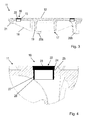
- Fig. 5 an alternative or additional embodiment of the pressure relief device 16 is shown, wherein the cap 22 is formed substantially plate-shaped and rests on a circumferential projection 28 of the lid 11.
- the cap 22 is stepped according to its edge 24 formed.
- a pin 29 Centrally attached to an inner side of the cap 22, a pin 29 which is guided by a arranged on the underside 17 of the lid 11 cage 30.
- the pin has at its free end an adjustable stop 31, wherein between the cage 30 and the stop 31, a spring element 32 is arranged in the form of a helical compression spring.
- the spring element 32 exerts a force in the closing direction on the cap 22 via the pin 29, so it pulls it into the opening 15, so to speak. This ensures a secure, watertight closure of the opening 15 through the cap 22.
- the spring force can be adjusted so that both a traffic-proof attachment and an optimal opening pressure for the valve function is achieved.
- FIG. 5 While in Fig. 5 an embodiment is shown in which only a central opening in the lid 11 and accordingly only a spring-loaded cap 22 is provided, shows Fig. 6 an embodiment with a plurality of openings 15 and pressure relief devices 16.
- the caps 22 have compared to the embodiment according to Fig. 4 a reduced Diameter, but are otherwise designed similar.
- each aperture 15 is associated with a cap 22 and a coaxially arranged cage 30.
- Fig. 7 is the pressure relief device 16, as in the embodiment according to Fig. 6 is used, shown in an enlarged sectional view.
- the plate-shaped cap 22 has on its underside at its base 23 a thickening 33. This is formed from a plastic and provides for an improved sealing and for a simplified attachment of the pin 29 to the cap 22.
- the pin 22 is guided by a arranged on the bottom 17 of the lid 11 cage 30 and has at his End of a designed as a nut stop 31.
- a spring element designed as a helical compression spring is clamped between the stop 31 and the cage 30 and pulls the cap 22 into the opening 15.
- the cap 22 acts as a valve plate of a spring-loaded overload valve.
- Fig. 8 shows a further embodiment of the manhole cover 9 according to the invention, in which the locking bolt 20 are movably connected to the lid 1, that the lid 11 perpendicular to its extension relative to the locking bolt 20 against a force applied by spring elements 32 spring force of his investment in the frame, not shown can remove.
- the lid 11 thus acts as a valve plate of a spring-loadedrichelastrventils.
- the locking bolt 20 take over the function of the cages 30 in the previous embodiments. Accordingly, the pin 29 is guided in each case by a locking bolt 20, wherein in each case a spring element between the pin 29 located on the stop 31 and the locking bolt is clamped.
- the lid 11 is pulled into the frame, not shown, and held accordingly safe.
- the spring force can be adjusted so that both a traffic-proof attachment and an optimal opening pressure for the valve function is achieved.
- the pressure relief device may also be positioned at other locations of the lid. Any number of pressure relief devices may be provided, with a symmetrical arrangement appears advantageous.
- the pressure relief device as a kind of bursting cap or as a spring-loaded overload valve also additional designs are conceivable, for example the use of an elastomeric sealing element. It can be influenced by the choice of the material of the cap, preferably plastic or metal, the holding forces and the sealing effect.
Abstract
Die Erfindung betrifft eine Schachtabdeckung mit einem Deckel (11) und einem Rahmen, wobei der Deckel (11) tragwasserdicht an den Rahmen anlegbar ist. Um auch bei starken Regenfällen und großer Wasserzunahme im Kanalsystem die Gefahr von Explosionen durch hohen Druckanstieg der im Kanalsystem eingeschlossenen Luft zu beseitigen, weist die Schachtabdeckung (9) eine Druckentlastungeinrichtung (16) auf.The invention relates to a manhole cover with a lid (11) and a frame, wherein the lid (11) can be applied watertight to the frame. In order to eliminate the risk of explosions due to high pressure rise of the trapped air in the duct system even in heavy rainfall and large water increase in the duct system, the manhole cover (9) on a pressure relief device (16).
Description
Die Erfindung betrifft eine Schachtabdeckung bzw. einen entsprechenden Aufsatz, die einen Deckel und einen Rahmen aufweist, wobei der Deckel tragwasserdicht an den Rahmen anlegbar ist.The invention relates to a manhole cover or a corresponding attachment, which has a lid and a frame, wherein the lid can be applied watertight to the frame.
Schachtabdeckungen umfassen in der Regel einen Deckel und einen Rahmen, auf den der Deckel im verschlossenen Zustand mit mindestens einer, an seiner Unterseite ausgebildeten Anlagefläche anliegt. Der Deckel ist üblicherweise geschlossen geformt und wirkt derartig mit den Rahmen zusammen, dass ein tragwasserdichter und geruchsdichter Verschluss erhalten wird.Manhole covers usually comprise a lid and a frame, on which the lid rests in the closed state with at least one, formed on its underside contact surface. The lid is usually closed-shaped and cooperates with the frames to provide a watertight and odor-tight seal.
Die Deckel werden in der Regel aus Gusseisen hergestellt, das eine relativ kostengünstige Herstellung ermöglicht und gleichzeitig ausreichend robust ist. Die Deckel halten so auch größeren Druckbelastungen, wie sie beispielsweise durch darüber fahrende Fahrzeuge verursacht werden, problemlos stand. Darüber hinaus führt der Einsatz von Gusseisen zu einem relativ hohen Eigengewicht, was zu einer dichten Anlage am Rahmen führt und damit eine gasdichte Ausführung erleichtert.The lids are usually made of cast iron, which allows a relatively inexpensive production and at the same time is sufficiently robust. The lids thus also withstand greater pressure loads, such as those caused by moving vehicles, stood without any problems. In addition, the use of cast iron leads to a relative high dead weight, which leads to a dense system on the frame and thus facilitates a gas-tight design.
Gasdichte Schachtabdeckungen werden zum Beispiel bei Oberflächenwasser führenden Kanalsystemen eingesetzt. Bei starken Regenfällen werden derartige Kanalsysteme relativ schnell mit Wasser gefüllt, wobei die im Kanalsystem enthaltene Luft komprimiert wird und sich in erhabenen Stellen des Kanalsystems sammelt. Derartige Stellen sind beispielsweise Domschächte, die in der Regel tagwasserdicht und geruchsdicht verschlossen sind.Gas-tight manhole covers are used, for example, in surface water-carrying duct systems. In heavy rains such channel systems are filled relatively quickly with water, wherein the air contained in the channel system is compressed and collects in raised areas of the channel system. Such sites are, for example, manhole shafts, which are usually closed day-waterproof and odor-tight.
Dabei kann es zu einer relativ hohen Druckbelastung der verwendeten Schachtabdeckungen kommen. Aufgrund der physikalischen Gesetzmäßigkeiten verdoppelt sich der Druck der Luft bei einer Halbierung des zur Verfügung stehenden Volumens. Eine Wasserzunahme im Kanalsystem, die beispielsweise eine Halbierung des im Kanal verfügbaren Raumes bewirkt, führt also zu einer Verdopplung des Druckes der im Kanalsystem befindlichen Luft auf ca. 2 Bar. Bei einer weiteren Verringerung des verfügbaren Volumens um ein Viertel erfolgt eine nochmalige Druckverdopplung auf ca. 4 bar. Nach einer weiteren Volumenverringerung um ein Achtel liegt der Druck schon bei 16 bar. Der Druck der im Kanalsystem eingeschlossenen Luft steigt also exponentiell und liegt weit über dem möglichen hydrostatischen Druck des Wassers.This can lead to a relatively high pressure load of the manhole covers used. Due to the physical laws, the pressure of the air doubles when the available volume is halved. An increase in water in the duct system, which, for example, halves the space available in the duct, thus doubles the pressure of the air in the duct system to approximately 2 bar. If the available volume is reduced by a quarter, the pressure is doubled again to approx 4 bar. After a further reduction in volume by one-eighth, the pressure is already at 16 bar. The pressure of the trapped air in the duct system increases exponentially and is well above the possible hydrostatic pressure of the water.
Der hohe Druck führt zu einer hohen Explosionsgefahr. Sobald die Belastbarkeitsgrenze des Schachtkopfes und/oder der Schachtabdeckung bzw. des Deckels überschritten wird, kann es zu plötzlichen, starken Ausbrüchen kommen. Dabei wird in der Regel nicht nur der Schachtkopf, sondern auch dessen Umgebung wie beispielsweise eine Fahrbahndecke großflächig zerstört.The high pressure leads to a high risk of explosion. As soon as the load capacity limit of the shaft head and / or the shaft cover or the cover is exceeded, sudden, strong outbreaks can occur. In this case, not only the shaft head, but also its surroundings such as a road surface is destroyed over a large area as a rule.
Bestehende Systeme zur Druckentlastung reagieren häufig zu langsam bzw. zu träge und sind in bestehende Anlagen auch nur mit großem Aufwand nachrüstbar. Dies ist insbesondere deshalb von Bedeutung, weil Starkregenereignisse vermehrt auftreten und dadurch auch bestehende Anlagen sogar in flachen Gegenden mit geringem Gefälle im Kanalsystem betroffen sind.Existing systems for pressure relief often react too slowly or too slowly and can be retrofitted into existing systems only with great effort. This is particularly important because heavy rainfall events occur more frequently and thus also existing plants are affected even in shallow areas with a slight slope in the sewer system.
Der Erfindung liegt daher die Aufgabe zu Grunde, eine Schachtabdeckung bereit zu stellen, die die Nachteile des Standes der Technik beseitigt und insbesondere eine ausreichend schnell reagierende Druckentlastung des Kanalsystems ermöglicht. Darüber hinaus soll diese Schachtabdeckung auch in bestehenden Anlagen ohne großen Aufwand nachgerüstet werden können.The invention is therefore based on the object to provide a manhole cover, which eliminates the disadvantages of the prior art and in particular allows a sufficiently fast-acting pressure relief of the channel system. In addition, this manhole cover can be retrofitted in existing systems without much effort.
Hauptmerkmale der Erfindung sind im Anspruch 1 angegeben. Ausgestaltungen sind Gegenstand der Unteransprüche.Main features of the invention are specified in
Bei einer Schachtabdeckung mit einem Deckel und einem Rahmen, wobei der Deckel tragwasserdicht an den Rahmen anlegbar ist, ist erfindungsgemäß vorgesehen, dass die Schachtabdeckung eine Druckentlastungeinrichtung aufweist.In a manhole cover with a lid and a frame, wherein the lid can be applied watertight to the frame, it is provided according to the invention that the manhole cover has a pressure relief device.
Es wird also nicht zusätzlich zur Schachtabdeckung eine Druckentlastung vorgesehen, sondern die Druckentlastungeinrichtung in die Schachtabdeckung integriert. Ein Nachrüsten bestehender Anlagen kann dann durch einfachen Austausch der alten Schachtabdeckung durch eine erfindungsgemäße Schachtabdeckung erfolgen. Die Druckentlastung erfolgt dann beispielsweise an der höchsten Stelle und ist entsprechend effektiv. Dabei öffnet die Druckentlastungseinrichtung erst nach Überschreiten eines bestimmten Differenzdruckes, so dass sie im Normalfall und bei Druck von oben tragwasserdicht und geruchsdicht ist.It is therefore not in addition to the manhole cover provided a pressure relief, but integrated the pressure relief device in the manhole cover. Retrofitting existing systems can then be done by simply replacing the old manhole cover by a manhole cover according to the invention. The pressure relief then takes place, for example, at the highest point and is correspondingly effective. In this case, the pressure relief device opens only after exceeding a certain differential pressure, so that it is normally watertight and odor-tight in the normal case and at pressure from above.
In einer bevorzugten Ausgestaltung weist der Deckel mindestens eine Durchbrechung auf, in der die Druckentlastungseinrichtung angeordnet ist. Der Rahmen kann dabei wie üblich ausgebildet sein. Ein Nachrüsten kann dann gegebenenfalls durch einfachen Austausch des Deckels erfolgen. Da die Druckentlastungseinrichtung in einer Durchbrechung des Deckels angeordnet wird, kann deren Fläche relativ gering gehalten werden, so dass auch Belastungen der Druckentlastungseinrichtung beispielsweise durch über den Deckel fahrende Fahrzeuge gering gehalten werden. Darüber hinaus wird die Gesamtstabilität des Deckels nur geringfügig beeinflusst.In a preferred embodiment, the lid has at least one opening in which the pressure relief device is arranged. The frame can be designed as usual. Retrofitting can then optionally be done by simply replacing the lid. Since the pressure relief device is arranged in an opening of the lid, the surface can be kept relatively low, so that even loads on the pressure relief device are kept low, for example by moving over the lid vehicles. In addition, the overall stability of the lid is only slightly affected.
Dabei kann die Durchbrechung zentrisch im Deckel angeordnet sein. Alternativ oder zusätzlich kann der Deckel mehrere Durchbrechungen aufweisen, die insbesondere symmetrisch und gegebenenfalls auf einer Kreislinie angeordnet sind. Die Anzahl und Größe der Durchbrechungen hängt dabei beispielsweise mit den theoretisch zu erwartenden Druckstößen zusammen, die wiederum von der Bauform und Größe der Schächte bzw. des Kanalsystems abhängen.In this case, the opening can be arranged centrally in the lid. Alternatively or additionally, the cover may have a plurality of apertures, which are in particular arranged symmetrically and optionally on a circular line. The number and size of the openings depends, for example, with the theoretically expected pressure surges, which in turn depend on the design and size of the shafts or the channel system.
Zur Erreichung einer ausreichenden Stabilität können an einer Unterseite des Deckels insbesondere radial verlaufende Rippen ausgebildet sein. Diese Rippen können dabei insbesondere von einer zentrisch an der Unterseite ausgebildeten Wandung ausgehen. Die Durchbrechungen können dann zwischen den Rippen ausgebildet sein, so dass die Bereiche neben den Durchbrechungen durch die Rippen verstärkt sind.In order to achieve sufficient stability, in particular radially extending ribs may be formed on an underside of the lid. These ribs can emanate in particular from a centrally formed on the bottom wall. The apertures may then be formed between the ribs so that the areas adjacent to the apertures are reinforced by the ribs.
Bei einer zentrisch im Deckel ausgebildeten Durchbrechung ist es günstig, wenn die Wandung diese koaxial umrandet. Die Wandung sorgt dann auch im Bereich der Durchbrechung für eine hohe Stabilität des Deckels.In a centrally formed in the lid opening, it is advantageous if the wall surrounds them coaxially. The wall then ensures in the area of the opening for a high stability of the lid.
Wenn an der Oberseite mindestens eine Griffmulde eingeformt ist oder insbesondere zwei diametral gegenüberliegende Griffmulden vorgesehen sind, kann der Deckel relativ einfach mit einem Werkzeug ergriffen und die Schachtabdeckung geöffnet werden. Auch kann die Oberseite des Deckels strukturiert sein, um eine hohe Rutschfestigkeit zu erzielenIf at least one recessed grip is formed on the upper side or, in particular, two diametrally opposite gripping recesses are provided, the cover can be grasped relatively easily with a tool and the shaft cover can be opened. Also, the top of the lid may be textured to achieve high slip resistance
In einer besonders bevorzugten Ausgestaltung ist die Druckentlastungseinrichtung als Kappe ausgebildet, deren Umriss an die Form der Durchbrechung angepasst ist und die dicht in die Durchbrechung einsetzbar ist. Dabei wird die Kappe derartig in der Durchbrechung gehalten, dass eine Oberseite der Kappe im Wesentlichen bündig mit der Oberseite des Deckels abschließt. Die Durchbrechung kann insbesondere eine Kreisform aufweisen, wobei die Kappe ebenfalls eine runde Form aufweist. Dadurch ist eine dichte Verbindung relativ einfach realisierbar. Die Kappe kann dabei reibschlüssig oder kraftschlüssig in der Durchbrechung gehalten sein, wobei zusätzlich auch ein überwindbarer Formschluss vorgesehen werden kann.In a particularly preferred embodiment, the pressure relief device is designed as a cap whose outline is adapted to the shape of the opening and which is tightly inserted into the opening. The cap is held in the opening in such a way that an upper side of the cap is substantially flush with the upper side of the lid. The opening may in particular have a circular shape, wherein the cap also has a round shape. This makes a tight connection relatively easy to implement. The cap can be frictionally or non-positively held in the opening, in addition, a surmountable positive connection can be provided.
In einer bevorzugten Weiterbildung weist die Durchbrechung geneigte Seitenränder auf, wobei die Kappe an ihren Rändern entsprechend konisch ausgebildet ist. Dadurch können zum einen Fertigungstoleranzen ausgeglichen werden und zum anderen wird verhindert, dass bei Druck von oben die Kappe durch die Durchbrechung hindurch gedrückt wird. Auch verhindern die geneigten Seitenränder ein Verklemmen und ermöglichen auch bei einer Verpressung der Kappe in der Durchbrechung ein relativ einfaches Ausstoßen, sobald ein entsprechender schachtseitiger Druck auftritt. Die Kappe kann aufgrund der geneigten Seitenränder in der gewünschten Position in der Durchbrechung gehalten werden, ohne dass ein mechanischer Anschlag erforderlich ist. Durch die gleichzeitige konische Ausgestaltung der Ränder der Kappe wird eine relativ große Flächenberührung erhalten, mit der die Anforderungen an Tragwasserdichtigkeit und Geruchsdichtigkeit sicher erfüllt werden können.In a preferred embodiment, the opening has inclined side edges, the cap being correspondingly conical at its edges. As a result, on the one hand, manufacturing tolerances can be compensated for and on the other hand it is prevented that the cap is pressed through the opening when pressure is applied from above. Also prevent the inclined side edges jamming and allow for a compression of the cap in the opening a relatively simple ejection, as soon as a corresponding shaft-side pressure occurs. The cap can be kept in the desired position in the opening due to the inclined side edges, without a mechanical stop is required. Due to the simultaneous conical configuration of the edges of the cap, a relatively large surface contact is obtained, with the requirements of Tragwasserdichtigkeit and odor-tightness can be safely met.
Vorzugsweise weist die Kappe eine Grundfläche auf, von deren Innenseite eine umlaufende, insbesondere zylindrische Wandung ausgeht. Diese Wandung erhöht zum einen die Stabilität der Kappe und erleichtert zum anderen ein Einsetzen der Kappe in die Durchbrechung.Preferably, the cap has a base, from the inside of a circumferential, in particular cylindrical wall emanates. On the one hand, this wall increases the stability of the cap and, on the other hand, facilitates insertion of the cap into the opening.
Dabei kann vorgesehen sein, dass zwischen der Wandung und Seitenrändern der Durchbrechung mindestens eine Kontaktstelle ausgebildet ist. Die Kappe liegt also nicht nur mit ihren konischen Rändern, sondern auch mit der Wandung an den Seitenrändern der Durchbrechung an. Damit ergibt sich ein guter reibschlüssiger und gegebenenfalls kraftschlüssiger Halt der Kappe in der Durchbrechung.It can be provided that between the wall and side edges of the opening at least one contact point is formed. The cap is thus not only with its conical edges, but also with the wall at the side edges of the opening. This results in a good frictional and possibly non-positive retention of the cap in the opening.
Vorzugsweise ist an der Wandung mindestens eine nach außen ragende Hemmung angeordnet, die insbesondere als umlaufender Wulst ausgebildet ist. Diese Hemmung befindet sich dabei insbesondere in einem Abstand zur Unterseite der Kappe bzw. der Grundfläche, die einer Dicke des Deckels entspricht, so dass die Hemmung unterseitig zum Deckel angeordnet ist. Die Kappe wird dann zusätzlich formschlüssig in der Durchbrechung gehalten, wobei die Hemmung jedoch ausreichend leicht verformbar ist, um die Kappe bei Auftreten eines entsprechend großen schachtseitigen Druckes aus der Durchbrechung heraus drücken zu können. Ein Entfernen der Kappe beispielsweise durch Dritte von der Oberseite des Deckels aus wird durch die Hemmung aber verhindert oder zumindest erschwert.Preferably, at least one outwardly projecting escapement is arranged on the wall, which is designed in particular as a circumferential bead. This inhibition is located in particular at a distance from the underside of the cap or the base surface, which corresponds to a thickness of the lid, so that the escapement is arranged on the underside of the lid. The cap is then additionally held in a form-fitting manner in the opening, wherein the escapement, however, is sufficiently easily deformable in order to be able to press the cap out of the opening when a correspondingly large shaft-side pressure occurs. Removal of the cap, for example, by a third party from the top of the lid is prevented by the inhibition but at least difficult.
Bevorzugterweise weist die Kappe ein Kunststoffmaterial auf. Die Kappe ist damit kostengünstig als Spritzgussteil herstellbar. Darüber hinaus ein Kunststoffmaterial korrosionsfest und weist eine relativ geringe Dichte auf. Dementsprechend kann auch ein Gewicht der Kappe gering gehalten werden, was ein schnelles Ansprechen auf Druckstöße aufgrund geringer Trägheit ermöglicht. Darüber hinaus wird eine Verletzungsgefahr aufgrund einer herumfliegenden Kappe gering gehalten.Preferably, the cap has a plastic material. The cap is thus inexpensive to produce as an injection molded part. In addition, a plastic material corrosion resistant and has a relatively low density. Accordingly, a weight of the cap can be kept low, allowing a quick response to pressure surges due to low inertia. In addition, a risk of injury due to a flying cap is kept low.
In einer weiteren bevorzugten Ausführungsform ist die Kappe als federbelasteter Verschluss für die Durchbrechung ausgebildet. Die Kappe kann sich dann bei Auftreten eines erhöhten Druckes im Kanalsystem nicht vollständig vom Deckel entfernen und muss daher nach dem Ansprechen nicht ersetzt werden. Durch die Federbelastung wird eine sichere Positionierung der Kappe in der Durchbrechung erhalten, wobei die Kappe in Schließrichtung belastet ist. Dadurch ist eine gute Dichtigkeit gewährleistet. Darüber hinaus kann durch die Federbelastung relativ einfach eingestellt werden, ab welcher Druckdifferenz die Druckentlastungseinrichtung öffnen soll. Bei dieser Ausführungsform ist die Kappe insbesondere aus Metall bzw. aus Gusseisen ausgebildetIn a further preferred embodiment, the cap is designed as a spring-loaded closure for the opening. The cap can then not completely remove from the lid when an increased pressure in the channel system occurs and therefore does not need to be replaced after the response. By the spring load a secure positioning of the cap is obtained in the opening, wherein the cap is loaded in the closing direction. This ensures good tightness. In addition, can be adjusted by the spring load relatively easy, from which pressure difference to open the pressure relief device. In this embodiment, the cap is formed in particular of metal or cast iron
Dabei ist besonders bevorzugt, dass die Kappe an einer Innenseite mindestens einen Stift aufweist, der durch einen an der Unterseite des Deckels angeordneten Käfig geführt ist, wobei der Stift insbesondere zentrisch an der Kappe angeordnet ist. Die Kappe wird dann mit Hilfe des Stifts linear gegenüber dem Deckel geführt, wobei der schachtseitige Druck durch den Käfig auf die Unterseite der Kappe wirken kann und diese somit in Öffnungsrichtung belastet. Der Stift erstreckt sich dabei insbesondere senkrecht zum Deckel und axial zur Durchbrechung, so dass die Kappe ohne Verkanten aus der Durchbrechung herausdrückbar ist.It is particularly preferred that the cap has on an inner side at least one pin, which is guided by a arranged on the underside of the lid cage, wherein the pin is arranged in particular centrally on the cap. The cap is then guided by means of the pin linearly relative to the lid, wherein the shaft-side pressure can act through the cage on the underside of the cap and thus loaded in the opening direction. The pin extends in particular perpendicular to the cover and axially to the opening, so that the cap can be pressed out without tilting out of the opening.
Vorzugsweise weist der Stift einen insbesondere über eine Gewindepaarung verstellbaren Anschlag auf, wobei ein Federelement zwischen Anschlag und Käfig eingespannt ist. Mit einem verstellbaren Anschlag, der im einfachsten Fall als Gewindemutter ausgebildet ist, lässt sich die Vorspannung des Federelements und damit der zum Öffnen der Kappe erforderliche Druck relativ einfach einstellen. Dabei ist das Federelement insbesondere als Schraubendruckfeder ausgebildet ist, durch die der Stift geführt ist. Dies ergibt eine symmetrische Krafteinleitung und eine besonders raumsparende Anordnung.Preferably, the pin has a particular adjustable via a threaded mating stop, wherein a spring element between the stop and cage is clamped. With an adjustable stop, which is formed in the simplest case as a threaded nut, the bias of the spring element and thus the pressure required to open the cap can be adjusted relatively easily. In this case, the spring element is in particular designed as a helical compression spring, through which the pin is guided. This results in a symmetrical introduction of force and a particularly space-saving arrangement.
An der Innenseite der Kappe kann eine insbesondere aus Kunststoff gebildete Verdickung ausgebildet sein. Diese Verdickung kann die Verbindung zwischen Stift und Kappe verstärken und gegebenenfalls eine größere Kontaktfläche mit den Seitenrändern der Durchbrechung bewirken und damit die Dichtigkeit erhöhen.On the inside of the cap, a thickening formed in particular of plastic can be formed. This thickening can strengthen the connection between the pin and cap and possibly cause a larger contact area with the side edges of the opening and thus increase the tightness.
Eine einfache Positionierung der Kappe in der Durchbrechung wird dadurch erreicht, dass die Kappe an mindestens einem in die Durchbrechung ragenden Vorsprung aufliegt, wobei der Vorsprung insbesondere umlaufend ausgebildet ist. Die Kappe wird dann durch das Federelement gegen den Vorsprung gezogen und so in einer definierten axialen Position gehalten.A simple positioning of the cap in the opening is achieved in that the cap rests on at least one protruding into the opening projection, wherein the projection is in particular formed circumferentially. The cap is then pulled by the spring element against the projection and held in a defined axial position.
Vorzugsweise sind an der Unterseite des Deckels Verschlussriegel zur Befestigung des Deckels am Rahmen angeordnet. Der Rahmen weist dann vorteilhafterweise Ausnehmungen für die Verschlussriegel auf, wobei die Verschlussriegel und die Ausnehmungen insbesondere einen Bajonettverschluss bilden. Mit Hilfe der Verschlussriegel kann der Deckel dann tragwasserdicht und geruchsdicht mit dem Rahmen verbunden werden. Gegebenenfalls kann der Deckel durch die Verschlussriegel auch in Richtung Rahmen gezogen werden, um spielfrei am Rahmen anzuliegen und um die Dichtigkeit zu erhöhen.Preferably, locking latches for fastening the lid to the frame are arranged on the underside of the lid. The frame then advantageously has recesses for the locking latch, wherein the locking latch and the recesses in particular form a bayonet closure. With the help of the locking latch, the lid can then be connected watertight and odor-tight with the frame. Optionally, the lid can be pulled through the locking bolt in the direction of the frame to rest without play on the frame and to increase the tightness.
In einer bevorzugten Ausgestaltung ist der Deckel beweglich mit den Verschlussriegeln verbunden, wobei die Verschlussriegel über Federelemente in Richtung Deckel belastet sind. Der gesamte Deckel kann dann bei Auftreten eines ausreichend hohen schachtseitigen Überdrucks vom Rahmen abgehoben werden, so dass der Druck entweichen kann. Über die Federelemente lässt sich dann die Höhe des Drucks relativ einfach einstellen. Darüber hinaus wird der Deckel durch die Federelemente in Richtung Rahmen gezogen und sorgt so im Normalfall für einen dichten Abschluss zwischen Rahmen und Deckel. Die Federelemente wirken dabei insbesondere senkrecht zur Erstreckung des Deckels.In a preferred embodiment, the cover is movably connected to the locking latch, wherein the locking latch are loaded by spring elements in the direction of the lid. The entire lid can then be lifted from the frame at a sufficiently high shaft-side overpressure, so that the pressure can escape. About the spring elements can then adjust the amount of pressure relatively easy. In addition, the lid is pulled by the spring elements in the direction of the frame and thus ensures a tight seal between the frame and lid normally. The spring elements act in particular perpendicular to the extension of the lid.
In einer bevorzugten Weiterbildung sind mit dem Deckel fest verbundene Stifte durch die Verschlussriegel geführt, wobei die Stifte einen insbesondere verstellbaren Anschlag aufweisen und ein Federelement zwischen Verschlussriegel und Anschlag eingespannt ist. Die Stifte, die sich insbesondere senkrecht zum Deckel erstrecken, bewirken dann eine Linearführung des Deckels und Verhindern ein Verkanten des Deckels, wenn dieser durch schachtseitigen Überdruck geöffnet wird. Das bzw. die Federelemente können dabei als Schraubendruckfedern ausgebildet sein, die die Stifte umgeben. Damit wird eine symmetrische Krafteinleitung und raumsparende Anordnung erreicht.In a preferred embodiment, pins fixedly connected to the cover are guided through the locking bolt, wherein the pins have a particularly adjustable stop and a spring element is clamped between locking bolt and stop. The pins, which extend in particular perpendicular to the lid, then cause a linear guide of the lid and prevent tilting of the lid when it is opened by shaft-side overpressure. The or the spring elements may be formed as helical compression springs surrounding the pins. This achieves a symmetrical introduction of force and a space-saving arrangement.
Weitere Merkmale, Einzelheiten und Vorteile der Erfindung ergeben sich aus dem Wortlaut der Ansprüche sowie aus der folgenden Beschreibung von Ausführungsbeispielen anhand der Zeichnungen. Es zeigen:
- Fig. 1
- eine schematische Darstellung eines Kanalsystems,
- Fig. 2
- eine Draufsicht auf einen Deckel einer Schachtabdeckung,
- Fig. 3
- eine Schnittansicht einer ersten Ausführungsform,
- Fig. 4
- eine Detailansicht zu
Fig. 3 , - Fig. 5
- eine Schnittansicht einer weiteren Ausführungsform,
- Fig. 6
- eine räumliche Ansicht einer weiteren Ausführungsform,
- Fig. 7
- eine Detailansicht zu
Fig. 6 und - Fig. 8
- eine Schnittansicht einer weiteren Ausführungsform.
- Fig. 1
- a schematic representation of a channel system,
- Fig. 2
- a top view of a cover of a manhole cover,
- Fig. 3
- a sectional view of a first embodiment,
- Fig. 4
- a detailed view too
Fig. 3 . - Fig. 5
- a sectional view of another embodiment,
- Fig. 6
- a spatial view of another embodiment,
- Fig. 7
- a detailed view too
Fig. 6 and - Fig. 8
- a sectional view of another embodiment.
In
Im Kanalsystem eingeschlossene Luft 10 sammelt sich im oberen Bereich des Domschachtes 8 und wird dort durch das Wasser unter Druck gesetzt, ohne durch die Schachtabdeckung 9 entweichen zu können. Wie oben ausgeführt können dabei sehr hohe Drücke auftreten, was schlimmstenfalls zu einem gewaltsamen Entweichen unter Zerstörung der Schachtabdeckung 9 und deren Umgebung führt.Trapped in the
Erfindungsgemäß ist daher vorgesehen, die Schachtabdeckung 9 mit einer Druckentlastungseinrichtung zu versehen.According to the invention, it is therefore provided to provide the manhole cover 9 with a pressure relief device.
In
In
In
Die Kappe 22 weist eine relativ dicke Grundfläche 23 mit konischen Rändern 24 auf, wobei die Ränder 24 im gleichen Winkel wie Seitenränder 25 der Durchbrechung 15 geneigt sind. Dementsprechend wird zwischen den Rändern 24 der Kappe 22 und den Seitenrändern 25 der Durchbrechung 15 eine flächige Berührung erhalten, die ausreichend tragwasser- und geruchsdicht ist.The
Die Kappe 22 schließt bündig mit der Oberseite 12 des Deckels 11 ab. Unterseitig weist die Kappe 11 eine zylindrische Wandung 26 auf, die an ihrem von der Grundfläche abgewandten Ende eine nach außen ragende Hemmung 27 in Form einer umlaufenden Wulst aufweist. Die Wandung 26 dient zum leichteren Einsetzen der Kappe 22 in die Durchbrechung 15 und kommt mit einem unteren Ende der Seitenränder 25 der Durchbrechung 15 in Kontakt. Dadurch sorgt sie für einen spielfreien Halt der Kappe 22 in der Durchbrechung 15. Dabei wird durch die Hemmung 27 ein unbefugtes Entfernen der Kappe 22 verhindert.The
Die Kappe 22 ist dabei in die Durchbrechung 15 eingepresst und damit reibschlüssig und kraftschlüssig dicht in der Durchbrechung 15 gehalten, wobei durch die geneigten Seitenränder ein Durchstoßen der Kappe 22 von der Oberseite 12 zur Unterseite 17 verhindert wird.The
In
Zentrisch ist an einer Innenseite der Kappe 22 ein Stift 29 befestigt, der durch einen an der Unterseite 17 des Deckels 11 angeordneten Käfig 30 geführt ist. Der Stift weist an seinem freien Ende einen verstellbaren Anschlag 31 auf, wobei zwischen dem Käfig 30 und dem Anschlag 31 ein Federelement 32 in Form einer Schraubendruckfeder angeordnet ist. Das Federelement 32 übt über den Stift 29 eine Kraft in Schließrichtung auf die Kappe 22 aus, zieht diese also sozusagen in die Durchbrechung 15 hinein. Damit wird für einen sicheren, tragwasserdichten Verschluss der Durchbrechung 15 durch die Kappe 22 gesorgt. Die Federkraft lässt sich dabei so einstellen, dass sowohl eine verkehrssichere Befestigung als auch ein optimaler Öffnungsdruck für die Ventilfunktion erreicht wird.Centrally attached to an inner side of the
Während in
In
Die Erfindung ist nicht auf eine der vorbeschriebenen Ausführungsformen beschränkt, sondern in vielfältiger Weise abwandelbar.The invention is not limited to one of the above-described embodiments, but can be modified in many ways.
Neben den gezeigten Positionen kann die Druckentlastungseinrichtung auch an anderen Stellen des Deckels positioniert sein. Dabei können beliebige Anzahlen an Druckentlastungseinrichtungen vorgesehen sein, wobei eine symmetrische Anordnung vorteilhaft erscheint. Neben den gezeigten Ausführungsbeispielen der Druckentlastungseinrichtung als Art Berstkappe oder wie ein federbelastetes Überlastventil sind auch noch zusätzliche Ausführungen denkbar, beispielsweise die Verwendung eines elastomeren Dichtelements. Dabei können durch die Wahl des Materials der Kappe, vorzugsweise Kunststoff oder Metall, die Haltekräfte und die Dichtwirkung beeinflusst werden.In addition to the positions shown, the pressure relief device may also be positioned at other locations of the lid. Any number of pressure relief devices may be provided, with a symmetrical arrangement appears advantageous. In addition to the illustrated embodiments of the pressure relief device as a kind of bursting cap or as a spring-loaded overload valve also additional designs are conceivable, for example the use of an elastomeric sealing element. It can be influenced by the choice of the material of the cap, preferably plastic or metal, the holding forces and the sealing effect.
Sämtliche aus den Ansprüchen, der Beschreibung und der Zeichnung hervorgehenden Merkmale und Vorteile, einschließlich konstruktiver Einzelheiten, räumlicher Anordnungen und Verfahrensschritten, können sowohl für sich als auch in den verschiedensten Kombinationen erfindungswesentlich sein.All of the claims, the description and the drawings resulting features and advantages, including design details, spatial arrangements and method steps may be essential to the invention both in itself and in various combinations.
- 1.1.
- Kanalsystemchannel system
- 2.Second
- StraßeStreet
- 3.Third
- Schachtshaft
- 4.4th
- Schachtshaft
- 5.5th
- Kanalchannel
- 6.6th
- Kanalchannel
- 7.7th
- Hauptkanalmain channel
- 8.8th.
- Domschachtmanhole
- 9.9th
- Schachtabdeckungmanhole cover
- 10.10th
- Luftair
- 11.11th
- Deckelcover
- 12.12th
- Oberseitetop
- 13.13th
- Griffmuldegrip
- 14.14th
- Griffmuldegrip
- 15.15th
- Durchbrechungperforation
- 16.16th
- DruckentlastungseinrichtungPressure relief device
- 17.17th
- Unterseitebottom
- 18.18th
- Rippenribs
- 19.19th
- Wandungwall
- 20.20th
- Verschlussriegellocking latch
- 21.21st
- Anlageflächecontact surface
- 22.22nd
- Kappecap
- 23.23rd
- GrundflächeFloor space
- 24.24th
- Rändermargins
- 25.25th
- Seitenrändermargins
- 26.26th
- Wandungwall
- 27.27th
- Wulstbead
- 28.28th
- Vorsprunghead Start
- 29.29th
- Stiftpen
- 30.30th
- KäfigCage
- 31.31st
- Anschlagattack
- 32.32nd
- Federelementspring element
- 33.33rd
- Verdickungthickening
Claims (16)
Priority Applications (1)
| Application Number | Priority Date | Filing Date | Title |
|---|---|---|---|
| PL14185446T PL2857589T3 (en) | 2013-09-20 | 2014-09-18 | Bursting protection systems for shaft covers |
Applications Claiming Priority (1)
| Application Number | Priority Date | Filing Date | Title |
|---|---|---|---|
| DE102013110452.5A DE102013110452A1 (en) | 2013-09-20 | 2013-09-20 | manhole cover |
Publications (2)
| Publication Number | Publication Date |
|---|---|
| EP2857589A1 true EP2857589A1 (en) | 2015-04-08 |
| EP2857589B1 EP2857589B1 (en) | 2017-11-29 |
Family
ID=51589123
Family Applications (1)
| Application Number | Title | Priority Date | Filing Date |
|---|---|---|---|
| EP14185446.3A Active EP2857589B1 (en) | 2013-09-20 | 2014-09-18 | Bursting protection systems for shaft covers |
Country Status (3)
| Country | Link |
|---|---|
| EP (1) | EP2857589B1 (en) |
| DE (1) | DE102013110452A1 (en) |
| PL (1) | PL2857589T3 (en) |
Cited By (1)
| Publication number | Priority date | Publication date | Assignee | Title |
|---|---|---|---|---|
| CN111456095A (en) * | 2020-04-10 | 2020-07-28 | 嘉兴恒力建材科技有限公司 | Safe well lid that explosion-proof anti-well lid of intelligence pressure release was flown up |
Families Citing this family (3)
| Publication number | Priority date | Publication date | Assignee | Title |
|---|---|---|---|---|
| CN113235665B (en) * | 2021-06-08 | 2022-05-13 | 辽宁工程技术大学 | Well lid structure that can be used to municipal administration emergency drainage |
| CN113513046B (en) * | 2021-07-06 | 2023-06-09 | 广西北海精一电力器材有限责任公司 | Epoxy resin composite cover plate and manufacturing method thereof |
| CN117090246A (en) * | 2023-10-20 | 2023-11-21 | 山东鲁润塑业股份有限公司 | Split type polymer well lid that can auto-lock |
Citations (1)
| Publication number | Priority date | Publication date | Assignee | Title |
|---|---|---|---|---|
| WO2007146256A2 (en) * | 2006-06-12 | 2007-12-21 | Stadler David M | Manhole cover security lock with controlled pressure release |
Family Cites Families (4)
| Publication number | Priority date | Publication date | Assignee | Title |
|---|---|---|---|---|
| US1071577A (en) * | 1913-03-19 | 1913-08-26 | Charles E Rego | Device for preventing blowing off of manhole-covers. |
| US2025839A (en) * | 1932-05-12 | 1935-12-31 | Cons Gas Company Of New York | Manhole closure |
| DE3812077A1 (en) * | 1988-04-12 | 1988-12-08 | Eichelmann Horst | Double-walled lid with concrete filling |
| GB2504452B (en) * | 2012-05-30 | 2017-09-06 | Spencer Price Paul | Improvements in and relating to manhole covers |
-
2013
- 2013-09-20 DE DE102013110452.5A patent/DE102013110452A1/en not_active Withdrawn
-
2014
- 2014-09-18 EP EP14185446.3A patent/EP2857589B1/en active Active
- 2014-09-18 PL PL14185446T patent/PL2857589T3/en unknown
Patent Citations (1)
| Publication number | Priority date | Publication date | Assignee | Title |
|---|---|---|---|---|
| WO2007146256A2 (en) * | 2006-06-12 | 2007-12-21 | Stadler David M | Manhole cover security lock with controlled pressure release |
Cited By (1)
| Publication number | Priority date | Publication date | Assignee | Title |
|---|---|---|---|---|
| CN111456095A (en) * | 2020-04-10 | 2020-07-28 | 嘉兴恒力建材科技有限公司 | Safe well lid that explosion-proof anti-well lid of intelligence pressure release was flown up |
Also Published As
| Publication number | Publication date |
|---|---|
| DE102013110452A1 (en) | 2015-03-26 |
| PL2857589T3 (en) | 2018-05-30 |
| EP2857589B1 (en) | 2017-11-29 |
Similar Documents
| Publication | Publication Date | Title |
|---|---|---|
| EP2873894B1 (en) | Stopper | |
| EP1866051B1 (en) | Oil filter arrangement | |
| DE102007026543B4 (en) | drain plug | |
| EP1623749B1 (en) | Oil filter assembly | |
| EP2857589B1 (en) | Bursting protection systems for shaft covers | |
| DE102017011081A1 (en) | Filter system and filter element | |
| WO2016169754A1 (en) | Filter element having a removal element | |
| DE102009054628A1 (en) | Telescopic support for the construction sector | |
| EP3577726A1 (en) | Plug connector housing | |
| DE202007012400U1 (en) | Connecting device for media lines in the region of a wall duct and wall element | |
| DE102010032527A1 (en) | Closure arrangement for a resource container | |
| DE202009003184U1 (en) | Sealing device for sealing a breakthrough | |
| EP3204669B1 (en) | Drainage connector | |
| DE202010005089U1 (en) | Sterile containers for medical purposes | |
| DE19732885B4 (en) | Cover with safety lock for a container | |
| EP3689786A1 (en) | Waste receiving apparatus | |
| DE102019213029A1 (en) | Screw nut device | |
| DE102009043734A1 (en) | tube plugs | |
| DE3232178A1 (en) | Closure lid | |
| DE3337197A1 (en) | Valve for pressure containers, for example compressed-gas cylinders | |
| DE102011119819A1 (en) | fastening device | |
| DE10051444C2 (en) | Container closure and cover for this container closure | |
| DE102015215767A1 (en) | Door lock, arrangement for a vehicle with a door lock | |
| DE102015112670A1 (en) | jig | |
| DE3712309C1 (en) | Arrangement for preventing a product pipe from being drawn out, in the case of a domestic connection |
Legal Events
| Date | Code | Title | Description |
|---|---|---|---|
| PUAI | Public reference made under article 153(3) epc to a published international application that has entered the european phase |
Free format text: ORIGINAL CODE: 0009012 |
|
| 17P | Request for examination filed |
Effective date: 20140918 |
|
| AK | Designated contracting states |
Kind code of ref document: A1 Designated state(s): AL AT BE BG CH CY CZ DE DK EE ES FI FR GB GR HR HU IE IS IT LI LT LU LV MC MK MT NL NO PL PT RO RS SE SI SK SM TR |
|
| AX | Request for extension of the european patent |
Extension state: BA ME |
|
| R17P | Request for examination filed (corrected) |
Effective date: 20150727 |
|
| RBV | Designated contracting states (corrected) |
Designated state(s): AL AT BE BG CH CY CZ DE DK EE ES FI FR GB GR HR HU IE IS IT LI LT LU LV MC MK MT NL NO PL PT RO RS SE SI SK SM TR |
|
| GRAP | Despatch of communication of intention to grant a patent |
Free format text: ORIGINAL CODE: EPIDOSNIGR1 |
|
| INTG | Intention to grant announced |
Effective date: 20170622 |
|
| GRAS | Grant fee paid |
Free format text: ORIGINAL CODE: EPIDOSNIGR3 |
|
| GRAA | (expected) grant |
Free format text: ORIGINAL CODE: 0009210 |
|
| AK | Designated contracting states |
Kind code of ref document: B1 Designated state(s): AL AT BE BG CH CY CZ DE DK EE ES FI FR GB GR HR HU IE IS IT LI LT LU LV MC MK MT NL NO PL PT RO RS SE SI SK SM TR |
|
| REG | Reference to a national code |
Ref country code: CH Ref legal event code: EP |
|
| REG | Reference to a national code |
Ref country code: AT Ref legal event code: REF Ref document number: 950525 Country of ref document: AT Kind code of ref document: T Effective date: 20171215 |
|
| REG | Reference to a national code |
Ref country code: IE Ref legal event code: FG4D Free format text: LANGUAGE OF EP DOCUMENT: GERMAN |
|
| REG | Reference to a national code |
Ref country code: DE Ref legal event code: R096 Ref document number: 502014006387 Country of ref document: DE |
|
| REG | Reference to a national code |
Ref country code: NL Ref legal event code: FP |
|
| REG | Reference to a national code |
Ref country code: LT Ref legal event code: MG4D |
|
| PG25 | Lapsed in a contracting state [announced via postgrant information from national office to epo] |
Ref country code: SE Free format text: LAPSE BECAUSE OF FAILURE TO SUBMIT A TRANSLATION OF THE DESCRIPTION OR TO PAY THE FEE WITHIN THE PRESCRIBED TIME-LIMIT Effective date: 20171129 Ref country code: NO Free format text: LAPSE BECAUSE OF FAILURE TO SUBMIT A TRANSLATION OF THE DESCRIPTION OR TO PAY THE FEE WITHIN THE PRESCRIBED TIME-LIMIT Effective date: 20180228 Ref country code: LT Free format text: LAPSE BECAUSE OF FAILURE TO SUBMIT A TRANSLATION OF THE DESCRIPTION OR TO PAY THE FEE WITHIN THE PRESCRIBED TIME-LIMIT Effective date: 20171129 Ref country code: FI Free format text: LAPSE BECAUSE OF FAILURE TO SUBMIT A TRANSLATION OF THE DESCRIPTION OR TO PAY THE FEE WITHIN THE PRESCRIBED TIME-LIMIT Effective date: 20171129 Ref country code: ES Free format text: LAPSE BECAUSE OF FAILURE TO SUBMIT A TRANSLATION OF THE DESCRIPTION OR TO PAY THE FEE WITHIN THE PRESCRIBED TIME-LIMIT Effective date: 20171129 |
|
| PG25 | Lapsed in a contracting state [announced via postgrant information from national office to epo] |
Ref country code: RS Free format text: LAPSE BECAUSE OF FAILURE TO SUBMIT A TRANSLATION OF THE DESCRIPTION OR TO PAY THE FEE WITHIN THE PRESCRIBED TIME-LIMIT Effective date: 20171129 Ref country code: GR Free format text: LAPSE BECAUSE OF FAILURE TO SUBMIT A TRANSLATION OF THE DESCRIPTION OR TO PAY THE FEE WITHIN THE PRESCRIBED TIME-LIMIT Effective date: 20180301 Ref country code: HR Free format text: LAPSE BECAUSE OF FAILURE TO SUBMIT A TRANSLATION OF THE DESCRIPTION OR TO PAY THE FEE WITHIN THE PRESCRIBED TIME-LIMIT Effective date: 20171129 Ref country code: BG Free format text: LAPSE BECAUSE OF FAILURE TO SUBMIT A TRANSLATION OF THE DESCRIPTION OR TO PAY THE FEE WITHIN THE PRESCRIBED TIME-LIMIT Effective date: 20180228 Ref country code: LV Free format text: LAPSE BECAUSE OF FAILURE TO SUBMIT A TRANSLATION OF THE DESCRIPTION OR TO PAY THE FEE WITHIN THE PRESCRIBED TIME-LIMIT Effective date: 20171129 |
|
| PG25 | Lapsed in a contracting state [announced via postgrant information from national office to epo] |
Ref country code: EE Free format text: LAPSE BECAUSE OF FAILURE TO SUBMIT A TRANSLATION OF THE DESCRIPTION OR TO PAY THE FEE WITHIN THE PRESCRIBED TIME-LIMIT Effective date: 20171129 Ref country code: CY Free format text: LAPSE BECAUSE OF FAILURE TO SUBMIT A TRANSLATION OF THE DESCRIPTION OR TO PAY THE FEE WITHIN THE PRESCRIBED TIME-LIMIT Effective date: 20171129 Ref country code: DK Free format text: LAPSE BECAUSE OF FAILURE TO SUBMIT A TRANSLATION OF THE DESCRIPTION OR TO PAY THE FEE WITHIN THE PRESCRIBED TIME-LIMIT Effective date: 20171129 Ref country code: CZ Free format text: LAPSE BECAUSE OF FAILURE TO SUBMIT A TRANSLATION OF THE DESCRIPTION OR TO PAY THE FEE WITHIN THE PRESCRIBED TIME-LIMIT Effective date: 20171129 Ref country code: SK Free format text: LAPSE BECAUSE OF FAILURE TO SUBMIT A TRANSLATION OF THE DESCRIPTION OR TO PAY THE FEE WITHIN THE PRESCRIBED TIME-LIMIT Effective date: 20171129 |
|
| REG | Reference to a national code |
Ref country code: DE Ref legal event code: R097 Ref document number: 502014006387 Country of ref document: DE |
|
| PG25 | Lapsed in a contracting state [announced via postgrant information from national office to epo] |
Ref country code: SM Free format text: LAPSE BECAUSE OF FAILURE TO SUBMIT A TRANSLATION OF THE DESCRIPTION OR TO PAY THE FEE WITHIN THE PRESCRIBED TIME-LIMIT Effective date: 20171129 Ref country code: RO Free format text: LAPSE BECAUSE OF FAILURE TO SUBMIT A TRANSLATION OF THE DESCRIPTION OR TO PAY THE FEE WITHIN THE PRESCRIBED TIME-LIMIT Effective date: 20171129 Ref country code: IT Free format text: LAPSE BECAUSE OF FAILURE TO SUBMIT A TRANSLATION OF THE DESCRIPTION OR TO PAY THE FEE WITHIN THE PRESCRIBED TIME-LIMIT Effective date: 20171129 |
|
| PG25 | Lapsed in a contracting state [announced via postgrant information from national office to epo] |
Ref country code: MT Free format text: LAPSE BECAUSE OF FAILURE TO SUBMIT A TRANSLATION OF THE DESCRIPTION OR TO PAY THE FEE WITHIN THE PRESCRIBED TIME-LIMIT Effective date: 20171129 |
|
| PLBE | No opposition filed within time limit |
Free format text: ORIGINAL CODE: 0009261 |
|
| STAA | Information on the status of an ep patent application or granted ep patent |
Free format text: STATUS: NO OPPOSITION FILED WITHIN TIME LIMIT |
|
| 26N | No opposition filed |
Effective date: 20180830 |
|
| PG25 | Lapsed in a contracting state [announced via postgrant information from national office to epo] |
Ref country code: SI Free format text: LAPSE BECAUSE OF FAILURE TO SUBMIT A TRANSLATION OF THE DESCRIPTION OR TO PAY THE FEE WITHIN THE PRESCRIBED TIME-LIMIT Effective date: 20171129 |
|
| PG25 | Lapsed in a contracting state [announced via postgrant information from national office to epo] |
Ref country code: MC Free format text: LAPSE BECAUSE OF FAILURE TO SUBMIT A TRANSLATION OF THE DESCRIPTION OR TO PAY THE FEE WITHIN THE PRESCRIBED TIME-LIMIT Effective date: 20171129 |
|
| GBPC | Gb: european patent ceased through non-payment of renewal fee |
Effective date: 20180918 |
|
| REG | Reference to a national code |
Ref country code: BE Ref legal event code: MM Effective date: 20180930 |
|
| REG | Reference to a national code |
Ref country code: IE Ref legal event code: MM4A |
|
| PG25 | Lapsed in a contracting state [announced via postgrant information from national office to epo] |
Ref country code: IE Free format text: LAPSE BECAUSE OF NON-PAYMENT OF DUE FEES Effective date: 20180918 |
|
| PG25 | Lapsed in a contracting state [announced via postgrant information from national office to epo] |
Ref country code: FR Free format text: LAPSE BECAUSE OF NON-PAYMENT OF DUE FEES Effective date: 20180930 Ref country code: BE Free format text: LAPSE BECAUSE OF NON-PAYMENT OF DUE FEES Effective date: 20180930 |
|
| PG25 | Lapsed in a contracting state [announced via postgrant information from national office to epo] |
Ref country code: GB Free format text: LAPSE BECAUSE OF NON-PAYMENT OF DUE FEES Effective date: 20180918 |
|
| PG25 | Lapsed in a contracting state [announced via postgrant information from national office to epo] |
Ref country code: TR Free format text: LAPSE BECAUSE OF FAILURE TO SUBMIT A TRANSLATION OF THE DESCRIPTION OR TO PAY THE FEE WITHIN THE PRESCRIBED TIME-LIMIT Effective date: 20171129 |
|
| PG25 | Lapsed in a contracting state [announced via postgrant information from national office to epo] |
Ref country code: PT Free format text: LAPSE BECAUSE OF FAILURE TO SUBMIT A TRANSLATION OF THE DESCRIPTION OR TO PAY THE FEE WITHIN THE PRESCRIBED TIME-LIMIT Effective date: 20171129 Ref country code: HU Free format text: LAPSE BECAUSE OF FAILURE TO SUBMIT A TRANSLATION OF THE DESCRIPTION OR TO PAY THE FEE WITHIN THE PRESCRIBED TIME-LIMIT; INVALID AB INITIO Effective date: 20140918 |
|
| PG25 | Lapsed in a contracting state [announced via postgrant information from national office to epo] |
Ref country code: MK Free format text: LAPSE BECAUSE OF NON-PAYMENT OF DUE FEES Effective date: 20171129 |
|
| PG25 | Lapsed in a contracting state [announced via postgrant information from national office to epo] |
Ref country code: AL Free format text: LAPSE BECAUSE OF FAILURE TO SUBMIT A TRANSLATION OF THE DESCRIPTION OR TO PAY THE FEE WITHIN THE PRESCRIBED TIME-LIMIT Effective date: 20171129 Ref country code: IS Free format text: LAPSE BECAUSE OF FAILURE TO SUBMIT A TRANSLATION OF THE DESCRIPTION OR TO PAY THE FEE WITHIN THE PRESCRIBED TIME-LIMIT Effective date: 20180329 |
|
| PGFP | Annual fee paid to national office [announced via postgrant information from national office to epo] |
Ref country code: NL Payment date: 20230920 Year of fee payment: 10 Ref country code: LU Payment date: 20230921 Year of fee payment: 10 Ref country code: AT Payment date: 20230921 Year of fee payment: 10 |
|
| PGFP | Annual fee paid to national office [announced via postgrant information from national office to epo] |
Ref country code: PL Payment date: 20230908 Year of fee payment: 10 Ref country code: DE Payment date: 20230930 Year of fee payment: 10 |
|
| PGFP | Annual fee paid to national office [announced via postgrant information from national office to epo] |
Ref country code: CH Payment date: 20231001 Year of fee payment: 10 |