EP2857266B1 - Scharnieranordnung - Google Patents
Scharnieranordnung Download PDFInfo
- Publication number
- EP2857266B1 EP2857266B1 EP13187197.2A EP13187197A EP2857266B1 EP 2857266 B1 EP2857266 B1 EP 2857266B1 EP 13187197 A EP13187197 A EP 13187197A EP 2857266 B1 EP2857266 B1 EP 2857266B1
- Authority
- EP
- European Patent Office
- Prior art keywords
- hinge
- hinge member
- slot
- engagement means
- notch
- Prior art date
- Legal status (The legal status is an assumption and is not a legal conclusion. Google has not performed a legal analysis and makes no representation as to the accuracy of the status listed.)
- Active
Links
- 238000006073 displacement reaction Methods 0.000 claims description 58
- 230000001419 dependent effect Effects 0.000 claims 2
- 210000003660 reticulum Anatomy 0.000 description 53
- 238000003466 welding Methods 0.000 description 4
- 230000000295 complement effect Effects 0.000 description 3
- 238000012423 maintenance Methods 0.000 description 3
- 238000004519 manufacturing process Methods 0.000 description 2
- 230000006378 damage Effects 0.000 description 1
- 230000003116 impacting effect Effects 0.000 description 1
- 238000012986 modification Methods 0.000 description 1
- 230000004048 modification Effects 0.000 description 1
- 238000004806 packaging method and process Methods 0.000 description 1
Images


Classifications
-
- B—PERFORMING OPERATIONS; TRANSPORTING
- B60—VEHICLES IN GENERAL
- B60R—VEHICLES, VEHICLE FITTINGS, OR VEHICLE PARTS, NOT OTHERWISE PROVIDED FOR
- B60R21/00—Arrangements or fittings on vehicles for protecting or preventing injuries to occupants or pedestrians in case of accidents or other traffic risks
- B60R21/34—Protecting non-occupants of a vehicle, e.g. pedestrians
- B60R21/38—Protecting non-occupants of a vehicle, e.g. pedestrians using means for lifting bonnets
-
- B—PERFORMING OPERATIONS; TRANSPORTING
- B60—VEHICLES IN GENERAL
- B60R—VEHICLES, VEHICLE FITTINGS, OR VEHICLE PARTS, NOT OTHERWISE PROVIDED FOR
- B60R21/00—Arrangements or fittings on vehicles for protecting or preventing injuries to occupants or pedestrians in case of accidents or other traffic risks
- B60R21/34—Protecting non-occupants of a vehicle, e.g. pedestrians
- B60R2021/343—Protecting non-occupants of a vehicle, e.g. pedestrians using deformable body panel, bodywork or components
Definitions
- the present disclosure relates to a hinge arrangement for a bonnet of a vehicle.
- the disclosure further relates to a vehicle comprising such a hinge arrangement.
- Document EP 2 380 787 A1 discloses a hinge mechanism for a bonnet of a vehicle.
- the hinge mechanism provides a hinged connection between the bonnet and the body structure of the vehicle.
- the hinge mechanism comprises a first hinge member connectable to the bonnet, a second hinge member, having a first end and a second end, and a third hinge member connectable to the body structure.
- the first end of the second hinge member is connected to the first hinge member.
- the third hinge member comprises a first portion and a second portion.
- the second end of the second hinge member is pivotally connected to the third hinge member at the second portion.
- the second hinge member is arranged to engage with the first portion of the third hinge member, when the second hinge member is subjected to a longitudinal force, such that at least part of the longitudinal force is transferable to the first portion by means of the engagement.
- the first portion is adapted to take up forces in the longitudinal direction imparted on the first portion by the second hinge member.
- an improved hinge arrangement which is able to withstand a force having at least a longitudinal component, e.g. resulting from a frontal collision, in a controlled way.
- the object of the present disclosure is to overcome or ameliorate at least one of the disadvantages of the prior art, and/or to provide a useful alternative.
- hinge arrangement involves few parts and/or is easy to mount in the vehicle at the production facility.
- a hinge arrangement for a bonnet of a vehicle in use providing a hinged connection between the bonnet and a body of the vehicle.
- the vehicle has a longitudinal direction and a vertical direction.
- the hinge arrangement comprises
- the directions longitudinal, transverse and vertical relate to the vehicle. Longitudinal is along the normal driving direction. Transverse is perpendicular to the longitudinal direction but in the same horizontal plane, i.e. sideways or laterally in the vehicle. Vertical is perpendicular to that plane, i.e. in the height direction of the vehicle.
- the location words front and rear used below relate to the directions of the vehicle, where front is the part coming first in the normal forward driving direction.
- the directions and location words used herein to describe the hinge arrangement relate to the directions of the hinge arrangement when mounted in the vehicle.
- the hinge arrangement is arranged such that the displacement is a geometrically guided predefined displacement, which occurs in a zone of the hinge arrangement being defined in the first hinge member as being above and rearward of the first engagement means and in the second hinge member as being rearward of the second engagement means.
- the first engagement means may be adapted to act as a receiving means for the second engagement means, or vice versa.
- the second hinge member In the non-engaged state of the engagement members, the second hinge member is able move freely from the first hinge member while being pivotally connected at the first pivot axis in order to open the bonnet for e.g. maintenance and/or repair.
- the force having at least a longitudinal component can be transferred from the second hinge member to the first hinge member by means of the engagement of the first and second engagement means.
- the first and second hinge members may be arranged with a play between their respective engagement means, normally of some millimeters, allowing the second hinge member to move freely from the first hinge member, while being pivotally connected at the first pivot axis A1, when the engagement means are in the non-engaged state.
- the play may be between 0 and 15 mm, preferably between 1 and 10 mm, more preferably 2 and 5 mm in the longitudinal direction of the vehicle.
- the bonnet may further be arranged, such that opening of the bonnet is prevented, when the engagement means are in the engaged state, thereby reducing the risk of unintentional, and undesired, opening of the bonnet.
- the first hinge member may be attached to the body of the vehicle by any suitable fastening means, for example by screwing or by welding at a lower attachment portion. It may be attached directly to the body, or via an additional member, such as a bracket.
- the second hinge member may comprise an upper attachment portion for attachment to the bonnet by any suitable fastening means, for example by screwing or by welding.
- the second hinge member may be attachable to the bonnet via a third hinge member, which is pivotally connected to the second hinge member.
- a deployable bonnet is characterized in that the rear part of the bonnet may be raised to an "impact position", a so called deployed position or pop-up position, such that the distance between the bonnet and any hard engine parts is increased in order to reduce the injuries of a vulnerable road user impacting with the bonnet.
- the first portion of the first hinge member comprises at least the portion of the first hinge member comprising the first engagement means and the portion below of that.
- the first portion of the first hinge member may comprise the whole first hinge member, e.g. when the predefined displacement is arranged to occur between the first and the second hinge members.
- the first portion of the second hinge member comprises at least the portion of the second hinge member comprising the second engagement means and the portion forward of that.
- the first portion of the second hinge member may comprise the whole second hinge member, e.g. when the displacement is arranged to occur between the first and the second hinge members.
- the first portion of the second hinge member is arranged to be displaceable by a predefined displacement in relation to at least the first portion of the first hinge member in order to obtain the engagement of the first and/or second engagement means, when the second hinge member is subjected to the force.
- the parts of the hinge arrangement are displaced in relation to each other due to a predefined, and thereby controlled, displacement. If the force is high, there may also be additional deformation of the hinge arrangement.
- the predefined displacement may be geometrically guided, e.g. defined by selecting the geometry of a slot or a notch, which guides the displacement.
- the predefined displacement differs from prior art solutions, wherein the parts, e.g. the first and second hinge member move in relation to each other due to deformation of a least a portion of the first and/or second hinge member. As mentioned above, such a deformation may be difficult to perform in a controlled way.
- the displacement may occur between the first and the second hinge members, e.g. at the pivotal axis.
- the displacement may occur within the second hinge member, between the first portion and a second portion not comprising the second engagement means, i.e. being located rearward of the first portion.
- the displacement may occur within the first hinge member, between the first portion and a second portion not comprising the first engagement means, i.e. being located above and/or rearward of the first portion.
- the force may be substantially longitudinal. Such a force may arise due to a frontal collision.
- substantially longitudinal is meant that any vertical or transverse component of the force is less than the longitudinal component, preferably less than 75% of the longitudinal component, more preferably less than 50% of the longitudinal component and most preferably less than 25% of the longitudinal component.
- the displacement may be a substantially rearward displacement.
- substantially rearward is meant that any vertical or transverse component of the force is less than the rearward component, the rearward component being in a longitudinal direction of the vehicle, preferably less than 75% of the rearward component, more preferably less than 50% of the rearward component and most preferably less than 25% of the rearward component.
- the predefined displacement may comprise a longitudinal displacement distance d of 0 ⁇ d ⁇ 15 mm, preferably 1 ⁇ d ⁇ 10 mm, more preferably 2 ⁇ d ⁇ 5 mm in the longitudinal direction of the vehicle.
- the displacement may have a transverse or vertical component. If the first and second hinge members are arranged with a play between their respective engagement means, normally of some millimeters, the longitudinal displacement distance may be at least long enough to close the play.
- At least one of the first or second engagement means may comprise a hook arranged to grip around the other of the first or second engagement means or in a notch in the other of the first or second engagement means to obtain the engagement.
- the hook should preferably be wide enough to grip the other engagement means. If one hook is used, it is preferably located in a horizontal plane, such that it, at least when engaged, can prevent lateral movement, except for the few millimeters within the hook. If both engagement means comprises a hook, they are preferably oriented with a 90 degree angle to each other. A few millimetres of extra width within the hook ensures that the movement of the second hinge member during opening of the bonnet is not obstructed in any way.
- the hook shape may help to facilitate for the bonnet to deploy to the deployed position without any interference between the second hinge member and the first hinge member.
- the predefined displacement may be made between a first position of the first portion of the second hinge member in relation to the first portion of the first hinge member, in which first position the second hinge member is pivotally displaceable in relation to the first hinge member at the first pivot axis in order to open the bonnet, i.e. corresponding to the non-engaged state, and a second position of the first portion of the second hinge member in relation to the first portion of the first hinge member, corresponding to the engaged state of the first and second engagement means.
- the second position of the first portion of the second hinge member in relation to the first portion of the first hinge member is rearwards of the first position.
- the first portion of the second hinge member and/or the first portion of the first hinge member may be biased towards the first position, preferably biased by means of a resilient member, such as a spring.
- the characteristics of the resilient member may be selected to provide a suitable preselectable threshold level for the force.
- the first portion of the second hinge member and/or the first portion of the first hinge member may be held in the first position by means of a breakable holding member, which is selected such that the holding member breaks if the force having a longitudinal component exceeds a threshold level.
- the breaking member may be located in the slot.
- the predefined displacement may be defined by the geometry of a slot or notch comprised in one of the first or second hinge member, by means of a slide member moving in the slot or notch.
- the slide member may be attached to one of the hinge members or may be a separate unit, which may be inserted into a hole in the hinge member.
- the geometry of the slot or notch in that case defines the predefined displacement. Purely as an example, a slot or notch extending in the longitudinal direction will result in a predefined displacement in the longitudinal direction.
- the slot has a closed circumference, while the notch has an open end. Both the slot and the notch define a track for the slide member to move in. It is preferred to use the closed circumference of the slot, such that it is avoided that the slide member unintentionally is displaced out of the slot or notch.
- the slot or notch may be located in the first hinge member above the first engagement means.
- the region of the slot or notch in that case delimits the first portion of the first hinge member from the second portion of the first member.
- the two portions of the first hinge member in that case are displaceable in relation to each other. In the region of the slot or notch, there may be an overlap of the first and second portions.
- the slot or notch may be located in the second hinge member rearward of the second engagement means.
- the region of the slot or notch in that case delimits the first portion of the second hinge member from the second portion of the second hinge member.
- the two portions of the second hinge member in that case are displaceable in relation to each other. In the region of the slot or notch, there may be an overlap of the first and second portions.
- the slot or notch may be comprised in one of the first or second hinge member and the slide member may be arranged in the other of the first or second hinge member.
- the slide member may be arranged in the same of the first or second hinge member as the slot or notch. This may be the case if the predefined displacement occurs between the first and second portions of one of the hinge members.
- the slot or notch may be located at the pivotal connection of the first and second hinge members, a pivot pin providing the pivot axis forming the slide member moving in the slot or notch.
- the slide member may have any cross-sectional shape, which is suitable for displacement in the corresponding slot or notch, e.g. round, oval, square or rectangular.
- a slide member having a non-round cross-sectional shape is preferred, since a non-round shape reduces the risk of unintentional, or undesired, pivotal movement around the slide member.
- a first end of the slot or notch may define the above-mentioned first position and a second opposite end of the slot or notch may define the above-mentioned second position.
- the first position will be defined by the front end of the slot, and the second position by the rear end of the slot, such that the portion of the hinge arrangement, which is displaced by the predefined displacement, can move in a rearward direction in relation to the body of the vehicle, when subjected to the force, e.g. in case of a frontal collision.
- the slot or notch is located in the portion of the hinge arrangement, which is displaced by the predefined displacement, the first position will be defined by the rear end of the slot, and the second position by the front end of the slot, such that the portion of the hinge arrangement, which is displaced by the predefined displacement, can move in a rearward direction in relation to the body of the vehicle, when subjected to the force, e.g. in case of a frontal collision.
- the slot or notch may have a first width corresponding to the first position and a second width, being less than the first width, the second width being located adjacent to the first width, such that the slide member is arranged to pass the second width during displacement from the first position to the second position.
- the first width may be adapted to fit the diameter of the pivot pin or it may be slightly less.
- the pivot pin When the pivot pin is being displaced to the second position, it will pass a portion of the slot or notch having a second width which is less than the first width.
- the second width is also less than the diameter of the pivot pin.
- the second hinge member will be able to pass the second width, when being pushed by the longitudinal force, e.g. in case of a collision.
- the first position By using a second width adjacent to the first position, the first position will be well defined.
- the relation between the second width and the diameter of the pivot pin is selected to provide a suitable threshold level for when the force is large enough to trigger the predefined displacement from the first position to the second position.
- a resilient member may be used to bias the first portion of the second hinge member and/or the first portion of the first hinge member towards the first position, as mentioned above.
- the resilient member may in that case be located within the slot.
- the resilient member may extend between the one of the hinge members comprising the slot or notch and the pivot pin or the slide member.
- the resilient member may extend between the one of the hinge members comprising the slot or notch and the other hinge member. The task of the resilient member is to bias the first portion of the second hinge member relative to the first portion of the first hinge member to the first position.
- a vehicle comprising a bonnet, a body and a hinge arrangement according to above, the hinge arrangement providing a hinged connection between the bonnet and the body of the vehicle.
- the vehicle has a longitudinal direction and a vertical direction.
- front and rear used below relate to the vehicle, where front is the part coming first in the normal forward driving direction.
- the directions longitudinal, transverse and vertical also relate to the vehicle. Longitudinal is along the normal driving direction. Transverse is perpendicular to the longitudinal direction but in the same horizontal plane, i.e. sideways or laterally in the vehicle. Vertical is perpendicular to that plane.
- FIG. 1 is a schematic side view of a front end of a vehicle 10, here a car.
- the vehicle 10 has a longitudinal direction L, a transverse direction T and a vertical direction V.
- the vehicle 10 is provided with a bonnet 12, which covers an engine compartment 14 and allows access to the engine compartment 14 for maintenance and/or repair.
- the bonnet 12 is connected to the vehicle 10 by a hinge arrangement 16, normally one hinge arrangement 16 adjacent to each lateral side of the bonnet 12.
- a rear end 18 of the bonnet 12 is directed towards a windscreen 20 of the vehicle 10.
- the hinge arrangements 16 are located adjacent to the rear end 18 of the bonnet 12.
- Normally the bonnet 12 is in a closed position A covering the engine compartment 14.
- the bonnet 12 can be displaced to an open position B allowing normal access to the engine compartment 14 for maintenance and/or repair.
- the vehicle 10 is normally stationary when displacing the bonnet to the open position B.
- Some vehicles 1 may have a deployable bonnet, i.e. it is possible to displace the bonnet 12 to a deployed position, also called a pop-up position, e.g. after sensor input that the vehicle 10 is about to hit a vulnerable road user, such as a pedestrian or a cyclist, e.g. by means of an actuator 22.
- a vulnerable road user such as a pedestrian or a cyclist
- an actuator 22 Normally, one or more sensors (not shown) are used to detect a collision with the vulnerable road user. In case of such a collision, the actuator 22 is activated.
- the actuator 22 may be an inflatable member, such as a pedestrian airbag, a pyrotechnical device, a mechanical spring, a compressed-air piston, an electrical lifter, a rack or a lifting arm.
- the bonnet 12 When the bonnet 12 is in the deployed position, a distance is formed between the bonnet 12 and hard parts of the engine, allowing deflection of the bonnet 12 without the risk of the head of the vulnerable road user hitting any hard parts of the engine.
- the bonnet 12 may be raised at both ends, but normally the rear end 18 is raised to a higher position than the front end.
- the distance formed between the bonnet 12 and the hard parts of the engine is typically between 50 and 130 millimetres.
- hinge arrangement according to this disclosure is suitable both for bonnet arrangements being able to assume the deployed position, as well as for bonnet arrangements not being able to assume the deployed position.
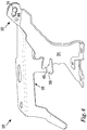
- FIG. 2 a side view of a hinge arrangement 16 in accordance with a first embodiment is shown, assuming that the bonnet 12, to which the hinge arrangement 16 is arranged, is in the closed position A.
- the hinge arrangement 16 comprises a first hinge member 24 and a second hinge member 26.
- the first hinge member 24 is adapted to be attached to a body 28 of said vehicle 10 by any suitable fastening means, for example by screwing or by welding at a lower attachment portion 30.
- the second hinge member 26 comprises a hinge arm extending substantially in the longitudinal direction L of the vehicle 10.
- a rear end 32 of the second hinge member 26 is pivotally connected to the first hinge member 24 at a first pivot axis A1, e.g. by means of e.g. a pivot pin 34.
- the pivot pin 34 may be attached to the second hinge member 26 or may be a separate unit, which may be inserted into a pin hole in the second hinge member 26.
- the second hinge member 26 comprises an upper attachment portion 36 for attachment to the bonnet 12 by any suitable fastening means, for example by screwing or by welding.
- the second hinge member 26 may be attachable to the bonnet 12 via a third hinge member, which is pivotally connected to the second hinge member 24.
- Deployable bonnets and their functions are known to the skilled person e.g. from document EP 2 380 787 A1 .
- the second hinge member 26 comprises a second engagement means 38, in the illustrated example having the shape of a hook located in a substantially horizontal plane.
- the first hinge member 24 comprises a first engagement means 40, in this case a notch located in a substantially vertical plane, which is adapted to act as a receiving means for the second engagement means 38, i.e. the hook 38 is adapted to be able grip around the notch 40.
- Figure 2 illustrates the first 40 and second engagement means 38 in a non-engaged state relative to each other
- Figure 4 which is described below, illustrates the first 40 and second engagement means 38 in an engaged state relative to each other.
- first 24 and second 26 hinge members normally of some millimeters, allowing the second hinge member 26 to move freely from the first hinge member 24, while being pivotally connected at the first pivot axis A1, when the bonnet 12 is opened towards the open position B.
- the first 40 and second engagement means 38 are arranged such that they, when engaged with each other, can transfer a force having at least a longitudinal component. Such a force may arise due to a frontal collision.
- the engagement will in that case reduce the risk, and preferably avoid the risk, of the bonnet 12 intruding into the windscreen 20 by taking up at least a portion of the force and/or decelerating the rearward movement of the bonnet 12.
- the first hinge member 24 comprises a slot 42 located at an upper end 44 of the first hinge member 24.
- the slot 42 is arranged to receive the pivot pin 34 allowing pivotal displacement of the second hinge member 26 in relation to the first hinge member 24 for opening of the bonnet 12.
- the geometry of the slot 42 guides the displacement of the second hinge member 26 in relation to the first hinge member 24, when subjected to the force having at least a longitudinal component. Thereby the displacement is performed in a predefined controllable way.
- Figure 3 shows a detailed view of the upper end 44 of the first hinge member 24 comprising the slot 42, the rear end 32 of the second hinge member 26 and the pivot pin 34.
- the pivot pin 34 is in the illustrated embodiment attached to the second hinge member 26.
- the two ends of the slot 42 define a first position 46, corresponding to the non-engaged state of the engagement means 38, 40 illustrated in Figures 2 and 3 , and a second position 48 corresponding to the engaged state of the engagement means 38, 40 illustrated in Figures 4 and 5 .
- the slot 42 has a first width w1 when the pivot pin 34 is in the first position 46.
- the first width w1 may be adapted to fit the diameter of the pivot pin 34 or it may be slightly less.
- the pivot pin 34 has a head with a large diameter helping it to stay in place.
- the pivot pin 34 When the pivot pin 34 is being displaced to the second position 48, it will pass a portion of the slot 42 having a second width w2, which is less than the first width w1.
- the second width w2 is also less than the diameter of the pivot pin 34.
- the second hinge member 26 will be able to pass the second width w2, when being pushed by the force, e.g. in case of a collision.
- the first position 46 will be well defined.
- the relation between the second width w2 and the diameter of the pivot pin 34 is selected to provide a suitable threshold level for when the force is large enough to trigger the predefined displacement from the first position 46 to the second position 48.
- the rear end 32 of the second hinge member 26 may instead comprise the slot, and the upper end 44 of the first hinge member 24 may instead have a pivot pin attached thereto, the pivot pin being displaceable in the slot, thereby allowing a predefined displacement of the second hinge member 26 in relation to the first hinge member 24 in order to reach the engaged state of the engagement means 38,40.
- Figures 4 and 5 illustrate the hinge arrangement of Figures 2 and 3 , when the first 40 and second engagement means 38 are in the engaged state relative to each other.
- the hook 38 grips around the notch 40. Due to the hook shape, a lateral movement between the second hinge member 26 and the first hinge member 24 within the hinge arrangement 16 is prevented, except for a few millimeters within the hook 38.
- Figure 5 shows a detailed view of the upper end 44 of the first hinge member 24 comprising the slot 42, the rear end 32 of the second hinge member 26 and the pivot pin 34.
- the pivot pin 34 is in the second position 48 defined by the rear end of the slot 42.
- FIG. 6 illustrates a hinge arrangement 116 according to a second embodiment.
- the second hinge member 126 comprises a front portion 150 and a rear portion 152.
- the second engagement means 38 are comprised in the front portion 150.
- the other of the front portion 150 or the rear portion 152, in the illustrated example the front portion 150 comprises a slide member 154, located in the slot 142.
- the front portion 150 and the rear portion 152 overlap in the region of the slot 142.
- the rear portion 152 is further pivotally connected to the first hinge member 24 by means of the pivot pin 34 at the pivot axis A1 to provide the hinged connection, but cannot move longitudinally relative to the first hinge member 24 at the pivot axis A1.
- the slot 142 defines a first position 146, corresponding to the non-engaged state of the first 40 and second engagement means 38, and a second position 148 being rearward of the first position 146 corresponding to the engaged state of the first 40 and second engagement means 38.
- the front portion 150 comprising the second engagement means 38 will be displaced rearwards, while the slide member 154 moves in the slot 142 to the second position 148.
- the rear portion 152 is connected to the body 28 of the vehicle 10 via the first hinge member 24, such that the predefined displacement occurs between the front portion 150 and the rear portion 152.
- FIG. 7 illustrates a hinge arrangement 216 according to a third embodiment. Most components are similar to the first embodiment and will not be mentioned again.
- the first hinge member 224 comprises a lower portion 250 and an upper portion 252.
- the first engagement means 40 is comprised in the lower portion 250.
- the other of the lower portion 250 or the upper portion 252, in the illustrated example the lower portion 250 comprises a slide member 254, located in the slot 242.
- the second hinge member 26 is pivotally connected to the upper portion 252 by means of the pivot pin 34 at the pivot axis A1 to provide the hinged connection, but cannot move longitudinally relative to the upper portion 252 at the pivot axis A1.
- the slot 242 defines a first position 246, corresponding to the non-engaged state of the first 40 and second engagement means 38, and a second position 248 corresponding to the engaged state of the first 40 and second engagement means 38.
- the second hinge member 26 comprising the second engagement means 38 will be displaced rearwards together with the upper portion 252 of the first hinge member 224, while the slide member 254 moves in the slot 242 to the second position 248.
- the predefined displacement occurs between the upper portion 252 and the lower portion 250 of the first hinge member 224. Since the slot 242 in the illustrated example of Figure 7 is located in the portion of the hinge arrangement 16, which is displaced by the predefined displacement, the first position 246 corresponds to a rear end of the slot 242 and the second position 248 corresponds to a front end of the slot 242. This is opposite to the case for the first and second embodiments, where instead the slide member 34, 154 is located in the portion of the hinge arrangement 16, which is displaced by the predefined displacement.
- the slide member 154, 254 may have any cross-sectional shape, which is suitable for displacement in the corresponding slot 142, 242 or notch, e.g. round, oval, square or rectangular.
- a slide member having a non-round cross-sectional shape is preferred, since a non-round shape reduces the risk of unintentional, or undesired, pivotal movement around the slide member.
- the slot 42, 142, 242 is preferably substantially oriented in the longitudinal direction L, such that the second position 48, 148, 248, corresponding to an engaged state of the first 40 and second engagement means 38, is rearward of the first position 46,146 illustrated by the first and second embodiments, or in front of the first position 246 illustrated by the third embodiment, corresponding to a non-engaged state of the first 40 and second engagement means 38.
- the longitudinal displacement distance d between of the first position 46, 146, 246 and the second position 48, 148, 248 fulfills 0 ⁇ d ⁇ 15 mm, preferably 1 ⁇ d ⁇ 10 mm, more preferably 2 ⁇ d ⁇ 5 mm in the longitudinal direction.
- the longitudinal displacement distance d may be adapted such that the above-mentioned play between the first engagement means 40 and the second engagement means 38 is eliminated.
- the slot 42, 142, 242 may be located anywhere in a zone Z of the hinge arrangement 16, 116, 216 delimited in the forward direction by the second engagement means 38 and in the vertical direction by the first engagement means 40. See the grey-shaded area of Figure 8 .
- the engagement means 38, 40 are located outside of the zone Z.
- a first portion 50 of the first hinge member 24 comprises at least the portion of the first hinge member 24 comprising the first engagement means 40 and the portion below that.
- the first portion 50 of the first hinge member 24 may comprise the whole first hinge member 24, as illustrated by the first and second embodiments, or there may be a second portion 52 of the first hinge member 24 located above and/or rearward of the first portion 50, as illustrated by the third embodiment.
- the first 54 portion of the second hinge member 26 comprises at least the portion of the second hinge member 26 comprising the second engagement means 38 and the portion forward of that.
- the first portion 54 of the second hinge member 26 may comprise the whole second hinge member 26, as illustrated by the first and third embodiments, or there may be a second portion 56 of the second hinge member 26 located rearward of the first portion 54, as illustrated by the second embodiment.
- the displacement may occur between the first 24 and the second 26 hinge members, e.g. at the pivotal axis A1, as illustrated for the first embodiment, see Figures 2-5 .
- the first portions 50, 54 make up the whole hinge members 24, 26.
- the displacement may occur within the second hinge member 26, between the first portion 54 and the second portion 56, as illustrated for the second embodiment, see Figure 6 , wherein the front portion 150 corresponds to the first portion 54 and or the rear portion 152 to the second portion 56.
- the slot 142 is located within the zone Z.
- the displacement may occur within the first hinge member 24, between the first portion 50 and the second portion 52, as illustrated for the third embodiment, see Figure 7 , wherein the lower portion 250 corresponds to the first portion 50 and or the upper portion 252 to the second portion 52.
- the slot 242 is located within the zone Z.
- the width of the slot 42, 142, 242 may be so narrow that it clamps the pivot pin 34 or the slide member 154, 254, such that the pivot pin 34 or the slide member 154, 254 has to overcome a clamping force in order to move from the first position 46, 146, 246 to the second position.
- the clamping force on the pivot pin 34 or the slide member 154, 254 may in that case be selected to provide a suitable preselectable threshold level for the force.
- the pivot pin 34 or the slide member 154, 254 may be biased towards the first position 46, 146, 246, e.g. by means of a resilient member, such as a spring.
- the characteristics of the resilient member may be selected to provide a suitable preselectable threshold level for the force.
- the resilient member may be located within the slot 42, 142, 242.
- the resilient member may extend between the one of the hinge members comprising the slot 42, 142, 242 and the pivot pin 34 or the slide member 154, 254.
- the resilient member may extend between the one of the hinge members comprising the slot 42, 142, 242 and the other hinge member.
- the task of the resilient member is to bias the first portion of the second hinge member relative to the first portion of the first hinge member to the first position 46, 146, 246.
- the pivot pin 34 or the slide member 154, 254 may be held in said first position by means of a breakable holding member, not illustrated, which is selected such that the holding member breaks, if the hinge arrangement 16, 116, 216 is subjected to a force having a longitudinal component exceeding a suitable preselectable threshold level, thereby allowing displacement to the second position.
Claims (15)
- Scharnieranordnung (16, 116, 216) für eine Motorhaube (12) eines Fahrzeugs (10), wobei die Scharnieranordnung (16, 116, 216) im Gebrauch eine Scharnierverbindung zwischen der Motorhaube (12) und einer Karosserie (28) des Fahrzeugs (10) bereitstellt, wobei das Fahrzeug (10) eine Längsrichtung (L) und eine Vertikalrichtung (V) hat, und wobei die Scharnieranordnung (16, 116, 216) umfasst:- ein erstes Scharnierelement (24, 224), das ausgebildet ist, um direkt oder indirekt an der Karosserie (28) des Fahrzeugs (10) befestigt zu werden, und- ein zweites Scharnierelement (26, 126), das ausgebildet ist, um direkt oder indirekt an der Motorhaube (12) befestigt zu werden, wobei:das erste Scharnierelement (24, 224) und das zweite Scharnierelement (26, 126) an einer ersten Schwenkachse (A1), wodurch die Scharnierverbindung bereitgestellt wird, schwenkbar miteinander verbunden sind,ein erster Abschnitt (50, 250) des ersten Scharnierelements (24, 224) ein erstes Eingriffsmittel (40) umfasst, und ein erster Abschnitt (54, 150) des zweiten Scharnierelements (26, 126) ein zweites Eingriffsmittel (38) umfasst,das zweite Eingriffsmittel (38) angeordnet ist, um in das erste Eingriffsmittel (40) einzugreifen, wenn das zweite Scharnierelement (26, 126) einer Kraft mit mindestens einer Längskomponente ausgesetzt ist, so dass mindestens ein Teil der Kraft durch Eingreifen der ersten und zweiten Eingriffsmittel (38, 40) auf das erste Scharnierelement (24, 224) übertragbar ist,der erste Abschnitt (54, 150) des zweiten Scharnierelements (26, 126) angeordnet ist, um sich durch ein Verschieben im Verhältnis zum ersten Abschnitt (50, 250) des ersten Scharnierelements (24, 224) verschieben zu lassen, um so das Eingreifen der ersten und zweiten Eingriffsmittel (38, 40) zu erzielen, wenn das zweite Scharnierelement (26, 126) der Kraft ausgesetzt ist,dadurch gekennzeichnet, dassdie Scharnieranordnung (16, 116, 216) so angeordnet ist, dass das Verschieben ein geometrisch geführtes vordefiniertes Verschieben ist, das in einer Zone (Z) der Scharnieranordnung (16, 116, 216) erfolgt, die im ersten Scharnierelement (24, 224) als oberhalb und hinter dem ersten Eingriffsmittel (40) liegend sowie im zweiten Scharnierelement (26, 126) als hinter dem zweiten Eingriffsmittel (38) liegend definiert ist.
- Scharnieranordnung (16, 116, 216) nach Anspruch 1, bei der die Kraft im Wesentlichen in Längsrichtung wirkt und das vordefinierte Verschieben ein im Wesentlichen rückwärts erfolgendes Verschieben ist.
- Scharnieranordnung (16, 116, 216) nach einem der vorstehend aufgeführten Ansprüche, bei der das vordefinierte Verschieben eine Längsverschiebungsdistanz (d) umfasst, die 0<d<15 mm, vorzugsweise 1<d<10 mm und besonders bevorzugt 2<d<5 mm in der Längsrichtung (L) des Fahrzeugs (10) beträgt.
- Scharnieranordnung (16, 116, 216) nach einem der vorstehend aufgeführten Ansprüche, bei der mindestens eines der ersten oder zweiten Eingriffsmittel (38, 40) einen Haken umfasst, der angeordnet ist, um das andere der ersten oder zweiten Eingriffsmittel (38, 40) zu umgreifen, um so das Eingreifen zu erzielen.
- Scharnieranordnung (16, 116, 216) nach einem der vorstehend aufgeführten Ansprüche, bei der das vordefinierte Verschieben zwischen einer ersten Position (46, 146, 246) des ersten Abschnitts (54, 150) des zweiten Scharnierelements (26, 126) im Verhältnis zum ersten Abschnitt (50, 250) des ersten Scharnierelements (24, 224), wobei in dieser ersten Position (46, 146, 246) das zweite Scharnierelement (26, 126) im Verhältnis zum ersten Scharnierelement (24, 224) an der ersten Schwenkachse (A1) schwenkbar verschiebbar ist, und einer zweiten relativen Position (48, 148, 248), entsprechend einem Eingreifen der ersten und/oder zweiten Eingriffsmittel (38, 40), erfolgt, wobei die zweite Position (48, 148, 248) hinter der ersten Position (46, 146, 246) liegt.
- Scharnieranordnung (16, 116, 216) nach Anspruch 5, bei der der erste Abschnitt (54, 150) des zweiten Scharnierelements (26, 126) und/oder der erste Abschnitt (50, 250) des ersten Scharnierelements (24, 224) hin zur ersten Position (46, 146, 246), vorzugsweise durch ein elastisches Element, vorgespannt ist.
- Scharnieranordnung (16, 116, 216) nach einem der vorstehend aufgeführten Ansprüche, bei der der erste Abschnitt (54, 150) des zweiten Scharnierelements (26, 126) und/oder der erste Abschnitt (50, 250) des ersten Scharnierelements (24, 224) durch ein zerbrechbares Halteelement in der ersten Position (46, 146, 246) gehalten werden, wobei das Halteelement so ausgewählt ist, dass es zerbricht, wenn die Kraft mit einer Längskomponente einen Schwellenwert übersteigt.
- Scharnieranordnung (16, 116, 216) nach einem der vorstehend aufgeführten Ansprüche, bei der das vordefinierte Verschieben durch die Geometrie eines Schlitzes (42, 142, 242) oder einer Kerbe, der bzw. die in einem der ersten oder zweiten Scharnierelemente (24, 224; 26, 126) vorgesehen ist, mittels eines Gleitelements (34, 154, 254) definiert ist, das sich im Schlitz (42, 142, 242) oder in der Kerbe bewegt.
- Scharnieranordnung (16, 116, 216) nach Anspruch 8, bei der sich der Schlitz (42, 142, 242) oder die Kerbe im ersten Scharnierelement (24, 224) oberhalb des ersten Eingriffsmittels (40) oder im zweiten Scharnierelement (26, 126) hinter dem zweiten Eingriffsmittel (38) befindet, wobei der Schlitz (42, 142, 242) oder die Kerbe den ersten Abschnitt (50, 250; 54, 150) des ersten oder zweiten Scharnierelements (26, 126) begrenzt.
- Scharnieranordnung (16) nach Anspruch 8 oder 9, bei der der Schlitz (42) oder die Kerbe in einem der ersten (24) oder zweiten (26) Scharnierelemente vorgesehen ist, und wobei das Gleitelement (34) im anderen der ersten (24) oder zweiten (26) Scharnierelemente angeordnet ist.
- Scharnieranordnung (116, 216) nach Anspruch 8 oder 9, bei der das Gleitelement (154, 254) in demselben der ersten (224) oder zweiten (126) Scharnierelemente wie der Schlitz (142, 242) oder die Kerbe angeordnet ist.
- Scharnieranordnung (16) nach einem der Ansprüche 8 bis 10, bei der sich der Schlitz (42) oder die Kerbe an der Schwenkverbindung der ersten und zweiten Scharnierelemente (24, 26) befindet, wobei ein Schwenkstift (34), der die Schwenkachse (A1) bereitstellt, das Gleitelement bildet, das sich im Schlitz (42) oder in der Kerbe bewegt.
- Scharnieranordnung (16, 116, 216) nach einem der Ansprüche 8 bis 12, soweit von Anspruch 5 abhängig, bei der ein erstes Ende des Schlitzes (42, 142, 242) oder der Kerbe die erste Position (46, 146, 246) definiert und ein zweites entgegengesetztes Ende des Schlitzes (42, 142, 242) oder der Kerbe die zweite Position (48, 148, 248) definiert.
- Scharnieranordnung (16, 116, 216) nach einem der Ansprüche 8 bis 13, soweit von Anspruch 5 abhängig, bei der der Schlitz (42, 142, 242) oder die Kerbe eine erste Breite (w1), entsprechend der ersten Position (46, 146, 246), sowie eine zweite Breite (w2) hat, die geringer als die erste Breite (w1) ist, wobei die zweite Breite (w2) angrenzend an die erste Breite (w1) so vorgesehen ist, dass sich das Gleitelement (34, 154, 254) während des Verschiebens von der ersten Position (46, 146, 246) zur zweiten Position (48, 148, 248) an der zweiten Breite (w2) vorbeibewegt.
- Fahrzeug (10), das eine Motorhaube (12), eine Karosserie (28) und eine Scharnieranordnung (16, 116, 216) nach einem der vorstehend aufgeführten Ansprüche umfasst, wobei die Scharnieranordnung (16, 116, 216) eine Scharnierverbindung zwischen der Motorhaube (12) und der Karosserie (28) des Fahrzeugs (10) bereitstellt, wobei das Fahrzeug (10) eine Längsrichtung (L) und eine Vertikalrichtung (V) hat.
Priority Applications (1)
| Application Number | Priority Date | Filing Date | Title |
|---|---|---|---|
| EP13187197.2A EP2857266B1 (de) | 2013-10-03 | 2013-10-03 | Scharnieranordnung |
Applications Claiming Priority (1)
| Application Number | Priority Date | Filing Date | Title |
|---|---|---|---|
| EP13187197.2A EP2857266B1 (de) | 2013-10-03 | 2013-10-03 | Scharnieranordnung |
Publications (2)
| Publication Number | Publication Date |
|---|---|
| EP2857266A1 EP2857266A1 (de) | 2015-04-08 |
| EP2857266B1 true EP2857266B1 (de) | 2017-06-21 |
Family
ID=49303798
Family Applications (1)
| Application Number | Title | Priority Date | Filing Date |
|---|---|---|---|
| EP13187197.2A Active EP2857266B1 (de) | 2013-10-03 | 2013-10-03 | Scharnieranordnung |
Country Status (1)
| Country | Link |
|---|---|
| EP (1) | EP2857266B1 (de) |
Families Citing this family (1)
| Publication number | Priority date | Publication date | Assignee | Title |
|---|---|---|---|---|
| US11492049B2 (en) * | 2018-04-04 | 2022-11-08 | Tesla, Inc. | Hinge assembly for a vehicle hood |
Family Cites Families (2)
| Publication number | Priority date | Publication date | Assignee | Title |
|---|---|---|---|---|
| EP2380787B1 (de) | 2010-04-21 | 2012-10-03 | Volvo Car Corporation | Scharniermechanismus |
| EP2634047B1 (de) * | 2012-03-02 | 2014-11-26 | Volvo Car Corporation | Scharniermechanismus |
-
2013
- 2013-10-03 EP EP13187197.2A patent/EP2857266B1/de active Active
Non-Patent Citations (1)
| Title |
|---|
| None * |
Also Published As
| Publication number | Publication date |
|---|---|
| EP2857266A1 (de) | 2015-04-08 |
Similar Documents
| Publication | Publication Date | Title |
|---|---|---|
| US6415882B1 (en) | Deployable hinge for pedestrian protection vehicle hood | |
| EP2902272B1 (de) | Haubenverriegelungsanordnung | |
| EP2239169B1 (de) | Fahrzeug mit einer Fußgängerschutzvorrichtung | |
| US7637344B2 (en) | Pedestrian protecting apparatus of vehicle hood | |
| US9010478B2 (en) | Safety arrangement for a vehicle | |
| EP2634047B1 (de) | Scharniermechanismus | |
| US7730990B2 (en) | Restraint system for a hood lift device | |
| EP2907704B1 (de) | Anordnung mit einer pyrotechnischen Vorrichtung und einer ersten mechanischen Struktur | |
| EP2380787B1 (de) | Scharniermechanismus | |
| JP4108020B2 (ja) | 車両のフード構造 | |
| US7416241B2 (en) | Grille and bonnet assembly for a vehicle | |
| EP2857266B1 (de) | Scharnieranordnung | |
| EP2857290B1 (de) | Scharnieranordnung | |
| JPH1120741A (ja) | 自動車のはね上げフード | |
| EP2108549B1 (de) | Scharnier für Automobilmotorhauben | |
| KR101271811B1 (ko) | 자동차용 후드 힌지장치 | |
| CN108166873B (zh) | 用于车辆的发动机罩铰链装置 | |
| KR101755452B1 (ko) | 차량용 후드 익스텐션 장치 | |
| US20160208517A1 (en) | Vehicle tailgate locking element guard | |
| EP3184376B1 (de) | Scharnieranordnung | |
| CN112977628A (zh) | 用于机动车辆的碰撞结构 | |
| EP3184375B1 (de) | Scharnieranordnung | |
| EP3323683B1 (de) | Scharnieranordnung | |
| JPH1149036A (ja) | 跳ね上げ式フード | |
| EP2918761A1 (de) | Scharnieranordnung |
Legal Events
| Date | Code | Title | Description |
|---|---|---|---|
| PUAI | Public reference made under article 153(3) epc to a published international application that has entered the european phase |
Free format text: ORIGINAL CODE: 0009012 |
|
| 17P | Request for examination filed |
Effective date: 20131003 |
|
| AK | Designated contracting states |
Kind code of ref document: A1 Designated state(s): AL AT BE BG CH CY CZ DE DK EE ES FI FR GB GR HR HU IE IS IT LI LT LU LV MC MK MT NL NO PL PT RO RS SE SI SK SM TR |
|
| AX | Request for extension of the european patent |
Extension state: BA ME |
|
| R17P | Request for examination filed (corrected) |
Effective date: 20151008 |
|
| RBV | Designated contracting states (corrected) |
Designated state(s): AL AT BE BG CH CY CZ DE DK EE ES FI FR GB GR HR HU IE IS IT LI LT LU LV MC MK MT NL NO PL PT RO RS SE SI SK SM TR |
|
| GRAP | Despatch of communication of intention to grant a patent |
Free format text: ORIGINAL CODE: EPIDOSNIGR1 |
|
| INTG | Intention to grant announced |
Effective date: 20170214 |
|
| GRAS | Grant fee paid |
Free format text: ORIGINAL CODE: EPIDOSNIGR3 |
|
| GRAA | (expected) grant |
Free format text: ORIGINAL CODE: 0009210 |
|
| AK | Designated contracting states |
Kind code of ref document: B1 Designated state(s): AL AT BE BG CH CY CZ DE DK EE ES FI FR GB GR HR HU IE IS IT LI LT LU LV MC MK MT NL NO PL PT RO RS SE SI SK SM TR |
|
| REG | Reference to a national code |
Ref country code: GB Ref legal event code: FG4D |
|
| REG | Reference to a national code |
Ref country code: CH Ref legal event code: EP |
|
| REG | Reference to a national code |
Ref country code: IE Ref legal event code: FG4D |
|
| REG | Reference to a national code |
Ref country code: AT Ref legal event code: REF Ref document number: 902643 Country of ref document: AT Kind code of ref document: T Effective date: 20170715 |
|
| REG | Reference to a national code |
Ref country code: DE Ref legal event code: R096 Ref document number: 602013022490 Country of ref document: DE |
|
| REG | Reference to a national code |
Ref country code: SE Ref legal event code: TRGR |
|
| REG | Reference to a national code |
Ref country code: NL Ref legal event code: MP Effective date: 20170621 |
|
| PG25 | Lapsed in a contracting state [announced via postgrant information from national office to epo] |
Ref country code: HR Free format text: LAPSE BECAUSE OF FAILURE TO SUBMIT A TRANSLATION OF THE DESCRIPTION OR TO PAY THE FEE WITHIN THE PRESCRIBED TIME-LIMIT Effective date: 20170621 Ref country code: FI Free format text: LAPSE BECAUSE OF FAILURE TO SUBMIT A TRANSLATION OF THE DESCRIPTION OR TO PAY THE FEE WITHIN THE PRESCRIBED TIME-LIMIT Effective date: 20170621 Ref country code: NO Free format text: LAPSE BECAUSE OF FAILURE TO SUBMIT A TRANSLATION OF THE DESCRIPTION OR TO PAY THE FEE WITHIN THE PRESCRIBED TIME-LIMIT Effective date: 20170921 Ref country code: GR Free format text: LAPSE BECAUSE OF FAILURE TO SUBMIT A TRANSLATION OF THE DESCRIPTION OR TO PAY THE FEE WITHIN THE PRESCRIBED TIME-LIMIT Effective date: 20170922 Ref country code: LT Free format text: LAPSE BECAUSE OF FAILURE TO SUBMIT A TRANSLATION OF THE DESCRIPTION OR TO PAY THE FEE WITHIN THE PRESCRIBED TIME-LIMIT Effective date: 20170621 |
|
| REG | Reference to a national code |
Ref country code: LT Ref legal event code: MG4D |
|
| REG | Reference to a national code |
Ref country code: AT Ref legal event code: MK05 Ref document number: 902643 Country of ref document: AT Kind code of ref document: T Effective date: 20170621 |
|
| PG25 | Lapsed in a contracting state [announced via postgrant information from national office to epo] |
Ref country code: NL Free format text: LAPSE BECAUSE OF FAILURE TO SUBMIT A TRANSLATION OF THE DESCRIPTION OR TO PAY THE FEE WITHIN THE PRESCRIBED TIME-LIMIT Effective date: 20170621 Ref country code: RS Free format text: LAPSE BECAUSE OF FAILURE TO SUBMIT A TRANSLATION OF THE DESCRIPTION OR TO PAY THE FEE WITHIN THE PRESCRIBED TIME-LIMIT Effective date: 20170621 Ref country code: BG Free format text: LAPSE BECAUSE OF FAILURE TO SUBMIT A TRANSLATION OF THE DESCRIPTION OR TO PAY THE FEE WITHIN THE PRESCRIBED TIME-LIMIT Effective date: 20170921 Ref country code: LV Free format text: LAPSE BECAUSE OF FAILURE TO SUBMIT A TRANSLATION OF THE DESCRIPTION OR TO PAY THE FEE WITHIN THE PRESCRIBED TIME-LIMIT Effective date: 20170621 |
|
| PG25 | Lapsed in a contracting state [announced via postgrant information from national office to epo] |
Ref country code: CZ Free format text: LAPSE BECAUSE OF FAILURE TO SUBMIT A TRANSLATION OF THE DESCRIPTION OR TO PAY THE FEE WITHIN THE PRESCRIBED TIME-LIMIT Effective date: 20170621 Ref country code: SK Free format text: LAPSE BECAUSE OF FAILURE TO SUBMIT A TRANSLATION OF THE DESCRIPTION OR TO PAY THE FEE WITHIN THE PRESCRIBED TIME-LIMIT Effective date: 20170621 Ref country code: RO Free format text: LAPSE BECAUSE OF FAILURE TO SUBMIT A TRANSLATION OF THE DESCRIPTION OR TO PAY THE FEE WITHIN THE PRESCRIBED TIME-LIMIT Effective date: 20170621 Ref country code: EE Free format text: LAPSE BECAUSE OF FAILURE TO SUBMIT A TRANSLATION OF THE DESCRIPTION OR TO PAY THE FEE WITHIN THE PRESCRIBED TIME-LIMIT Effective date: 20170621 Ref country code: AT Free format text: LAPSE BECAUSE OF FAILURE TO SUBMIT A TRANSLATION OF THE DESCRIPTION OR TO PAY THE FEE WITHIN THE PRESCRIBED TIME-LIMIT Effective date: 20170621 |
|
| PG25 | Lapsed in a contracting state [announced via postgrant information from national office to epo] |
Ref country code: IT Free format text: LAPSE BECAUSE OF FAILURE TO SUBMIT A TRANSLATION OF THE DESCRIPTION OR TO PAY THE FEE WITHIN THE PRESCRIBED TIME-LIMIT Effective date: 20170621 Ref country code: PL Free format text: LAPSE BECAUSE OF FAILURE TO SUBMIT A TRANSLATION OF THE DESCRIPTION OR TO PAY THE FEE WITHIN THE PRESCRIBED TIME-LIMIT Effective date: 20170621 Ref country code: ES Free format text: LAPSE BECAUSE OF FAILURE TO SUBMIT A TRANSLATION OF THE DESCRIPTION OR TO PAY THE FEE WITHIN THE PRESCRIBED TIME-LIMIT Effective date: 20170621 Ref country code: SM Free format text: LAPSE BECAUSE OF FAILURE TO SUBMIT A TRANSLATION OF THE DESCRIPTION OR TO PAY THE FEE WITHIN THE PRESCRIBED TIME-LIMIT Effective date: 20170621 Ref country code: IS Free format text: LAPSE BECAUSE OF FAILURE TO SUBMIT A TRANSLATION OF THE DESCRIPTION OR TO PAY THE FEE WITHIN THE PRESCRIBED TIME-LIMIT Effective date: 20171021 |
|
| REG | Reference to a national code |
Ref country code: DE Ref legal event code: R097 Ref document number: 602013022490 Country of ref document: DE |
|
| PLBE | No opposition filed within time limit |
Free format text: ORIGINAL CODE: 0009261 |
|
| STAA | Information on the status of an ep patent application or granted ep patent |
Free format text: STATUS: NO OPPOSITION FILED WITHIN TIME LIMIT |
|
| PG25 | Lapsed in a contracting state [announced via postgrant information from national office to epo] |
Ref country code: DK Free format text: LAPSE BECAUSE OF FAILURE TO SUBMIT A TRANSLATION OF THE DESCRIPTION OR TO PAY THE FEE WITHIN THE PRESCRIBED TIME-LIMIT Effective date: 20170621 |
|
| 26N | No opposition filed |
Effective date: 20180322 |
|
| PG25 | Lapsed in a contracting state [announced via postgrant information from national office to epo] |
Ref country code: MC Free format text: LAPSE BECAUSE OF FAILURE TO SUBMIT A TRANSLATION OF THE DESCRIPTION OR TO PAY THE FEE WITHIN THE PRESCRIBED TIME-LIMIT Effective date: 20170621 |
|
| REG | Reference to a national code |
Ref country code: CH Ref legal event code: PL |
|
| REG | Reference to a national code |
Ref country code: IE Ref legal event code: MM4A |
|
| REG | Reference to a national code |
Ref country code: FR Ref legal event code: ST Effective date: 20180629 |
|
| PG25 | Lapsed in a contracting state [announced via postgrant information from national office to epo] |
Ref country code: CH Free format text: LAPSE BECAUSE OF NON-PAYMENT OF DUE FEES Effective date: 20171031 Ref country code: LI Free format text: LAPSE BECAUSE OF NON-PAYMENT OF DUE FEES Effective date: 20171031 Ref country code: LU Free format text: LAPSE BECAUSE OF NON-PAYMENT OF DUE FEES Effective date: 20171003 |
|
| REG | Reference to a national code |
Ref country code: BE Ref legal event code: MM Effective date: 20171031 |
|
| PG25 | Lapsed in a contracting state [announced via postgrant information from national office to epo] |
Ref country code: SI Free format text: LAPSE BECAUSE OF FAILURE TO SUBMIT A TRANSLATION OF THE DESCRIPTION OR TO PAY THE FEE WITHIN THE PRESCRIBED TIME-LIMIT Effective date: 20170621 Ref country code: FR Free format text: LAPSE BECAUSE OF NON-PAYMENT OF DUE FEES Effective date: 20171031 Ref country code: BE Free format text: LAPSE BECAUSE OF NON-PAYMENT OF DUE FEES Effective date: 20171031 |
|
| PG25 | Lapsed in a contracting state [announced via postgrant information from national office to epo] |
Ref country code: MT Free format text: LAPSE BECAUSE OF NON-PAYMENT OF DUE FEES Effective date: 20171003 |
|
| PG25 | Lapsed in a contracting state [announced via postgrant information from national office to epo] |
Ref country code: IE Free format text: LAPSE BECAUSE OF NON-PAYMENT OF DUE FEES Effective date: 20171003 |
|
| PGFP | Annual fee paid to national office [announced via postgrant information from national office to epo] |
Ref country code: IT Payment date: 20181113 Year of fee payment: 14 |
|
| PGFP | Annual fee paid to national office [announced via postgrant information from national office to epo] |
Ref country code: GB Payment date: 20181011 Year of fee payment: 6 |
|
| PG25 | Lapsed in a contracting state [announced via postgrant information from national office to epo] |
Ref country code: HU Free format text: LAPSE BECAUSE OF FAILURE TO SUBMIT A TRANSLATION OF THE DESCRIPTION OR TO PAY THE FEE WITHIN THE PRESCRIBED TIME-LIMIT; INVALID AB INITIO Effective date: 20131003 |
|
| PG25 | Lapsed in a contracting state [announced via postgrant information from national office to epo] |
Ref country code: CY Free format text: LAPSE BECAUSE OF FAILURE TO SUBMIT A TRANSLATION OF THE DESCRIPTION OR TO PAY THE FEE WITHIN THE PRESCRIBED TIME-LIMIT Effective date: 20170621 |
|
| PG25 | Lapsed in a contracting state [announced via postgrant information from national office to epo] |
Ref country code: MK Free format text: LAPSE BECAUSE OF FAILURE TO SUBMIT A TRANSLATION OF THE DESCRIPTION OR TO PAY THE FEE WITHIN THE PRESCRIBED TIME-LIMIT Effective date: 20170621 |
|
| PG25 | Lapsed in a contracting state [announced via postgrant information from national office to epo] |
Ref country code: TR Free format text: LAPSE BECAUSE OF FAILURE TO SUBMIT A TRANSLATION OF THE DESCRIPTION OR TO PAY THE FEE WITHIN THE PRESCRIBED TIME-LIMIT Effective date: 20170621 |
|
| PG25 | Lapsed in a contracting state [announced via postgrant information from national office to epo] |
Ref country code: PT Free format text: LAPSE BECAUSE OF FAILURE TO SUBMIT A TRANSLATION OF THE DESCRIPTION OR TO PAY THE FEE WITHIN THE PRESCRIBED TIME-LIMIT Effective date: 20170621 |
|
| PG25 | Lapsed in a contracting state [announced via postgrant information from national office to epo] |
Ref country code: AL Free format text: LAPSE BECAUSE OF FAILURE TO SUBMIT A TRANSLATION OF THE DESCRIPTION OR TO PAY THE FEE WITHIN THE PRESCRIBED TIME-LIMIT Effective date: 20170621 |
|
| PG25 | Lapsed in a contracting state [announced via postgrant information from national office to epo] |
Ref country code: SE Free format text: LAPSE BECAUSE OF NON-PAYMENT OF DUE FEES Effective date: 20191004 |
|
| GBPC | Gb: european patent ceased through non-payment of renewal fee |
Effective date: 20191003 |
|
| PG25 | Lapsed in a contracting state [announced via postgrant information from national office to epo] |
Ref country code: GB Free format text: LAPSE BECAUSE OF NON-PAYMENT OF DUE FEES Effective date: 20191003 |
|
| P01 | Opt-out of the competence of the unified patent court (upc) registered |
Effective date: 20231212 |
|
| PGFP | Annual fee paid to national office [announced via postgrant information from national office to epo] |
Ref country code: DE Payment date: 20230920 Year of fee payment: 11 |