EP2857261A2 - Truck with tipping body - Google Patents
Truck with tipping body Download PDFInfo
- Publication number
- EP2857261A2 EP2857261A2 EP14187740.7A EP14187740A EP2857261A2 EP 2857261 A2 EP2857261 A2 EP 2857261A2 EP 14187740 A EP14187740 A EP 14187740A EP 2857261 A2 EP2857261 A2 EP 2857261A2
- Authority
- EP
- European Patent Office
- Prior art keywords
- load
- bearing structure
- side board
- base portion
- rotation
- Prior art date
- Legal status (The legal status is an assumption and is not a legal conclusion. Google has not performed a legal analysis and makes no representation as to the accuracy of the status listed.)
- Granted
Links
- 230000008878 coupling Effects 0.000 claims abstract description 19
- 238000010168 coupling process Methods 0.000 claims abstract description 19
- 238000005859 coupling reaction Methods 0.000 claims abstract description 19
- 230000001360 synchronised effect Effects 0.000 claims description 2
- 239000000463 material Substances 0.000 description 9
- 230000009977 dual effect Effects 0.000 description 2
- 239000004576 sand Substances 0.000 description 2
- 230000009194 climbing Effects 0.000 description 1
- 238000005516 engineering process Methods 0.000 description 1
- 238000000034 method Methods 0.000 description 1
- 230000010355 oscillation Effects 0.000 description 1
Images






Classifications
-
- B—PERFORMING OPERATIONS; TRANSPORTING
- B60—VEHICLES IN GENERAL
- B60P—VEHICLES ADAPTED FOR LOAD TRANSPORTATION OR TO TRANSPORT, TO CARRY, OR TO COMPRISE SPECIAL LOADS OR OBJECTS
- B60P1/00—Vehicles predominantly for transporting loads and modified to facilitate loading, consolidating the load, or unloading
- B60P1/04—Vehicles predominantly for transporting loads and modified to facilitate loading, consolidating the load, or unloading with a tipping movement of load-transporting element
- B60P1/26—Means for controlling movement of tailboards or sideboards
- B60P1/273—Providing interdependence between tipping movement and the latching or unlatching of a freely-swingable tailboard or sideboard
Definitions
- This invention relates to a truck with tipping body.
- the body can be tipped (and for this purpose it is rotatably mounted on the frame of the truck) and comprises at least one openable side board with dual opening modes (that is to say, board tipping downwards or oscillating about the upper part).
- the body comprises a load-bearing structure, a loading bed mounted on the load-bearing structure and at least four side boards, at least one of which is openable.
- the latter can be tipped and therefore at least one of the side boards must be openable.
- the openable side board is the one positioned at the rear of the body (therefore, this invention is mainly for that case), but in some applications it may also be one of the boards positioned at the sides of the body.
- this invention may be applied both on bodies which have only backward tipping, and on bodies with multiple tipping (three-sided).
- the openable side board is positioned at the unloading side of the loading bed to, in use, allow unloading of the material transported.
- the body comprises multiple unloading sides. In that case this invention may be applied to all of the unloading sides or to only one of them.
- the openable side board comprises a base portion, hookable to the load-bearing structure close to the loading bed, and a top portion, hookable to the load-bearing structure and distanced from the base portion.
- the body also comprises constraining means for rotatably and independently constraining the base portion and the top portion to the load-bearing structure.
- the openable side board can be selectively released from the load-bearing structure either manually at the top portion or automatically at the base portion during tipping of the body.
- the body comprises coupling means which allow that automatic releasing.
- Said coupling means may comprise for example a lever associated with a cam mechanism.
- the cam mechanism is sized in such a way that, when the body is angled at the predetermined angle, the lever disengages from the base portion and leaves the base portion free to be released from the load-bearing structure.
- the openable side board may alternatively be releasable from the load-bearing structure at the top portion, for example to facilitate an operator climbing onto the body and the pickup of objects positioned on the loading bed.
- the openable side board detaches from the body when it is released at the top portion and the body is tipped and angled at an angle at least equal to the predetermined angle.
- the lever disengages from the base portion, leaving it free to be released from the load-bearing portion, irrespective of whether or not the top portion is hooked to the load-bearing structure (and if the top portion is released from the load-bearing structure, the openable side board detaches from the body).
- That accidental detachment during unloading operations may involve, first, several risks for the safety of operators who may be located close to said side board, since they may be injured by the board falling.
- the detachment of the side board may cause damage to the board due to its impact on the ground.
- the body once the body has exceeded the predetermined tipping angle, if the board has not detached from the rest of the body, it may be the lever itself which damages it due to the position of the various parts relative to one another.
- the technical purpose which forms the basis of this invention is to provide a truck with tipping body which overcomes the above-mentioned disadvantages.
- the technical purpose of this invention it to provide a truck with tipping body for which there is no risk of accidental detachment of the openable side board during unloading operations.
- the technical purpose of this invention is to provide a truck with tipping body in which the openable side board cannot be damaged due to an accidental detachment during unloading operations.
- the numeral 1 denotes in its entirety a truck with tipping body according to this invention.
- this invention may be applied both to trucks 1 having bodies 3 which can be tipped backwards and to trucks 1 having bodies 3 which can also be tipped sideways (three-sided tipping bodies 3).
- the truck 1 comprises first a frame 2 (partly visible in the accompanying drawings), a cab (not visible in the accompanying drawings) mounted on the frame 2 and a tipping body 3 mounted on the frame 2. It should be noticed that, in use, the body 3 is mounted on the frame 2 to the rear of the cab according to a direction of movement of the truck 1 on the road.
- the body 3 may be tipped by thrust means (not visible in the accompanying drawings, but of the known type), for example an oil hydraulic cylinder, to allow, in use, unloading of the materials contained in the body 3.
- thrust means for example an oil hydraulic cylinder
- the body 3 comprises a front part (not visible in the accompanying drawings), substantially close to the cab of the truck 1, and a rear part 4 (partly visible in Figure 1 ), substantially distanced from the cab.
- Said body 3 comprises a load-bearing structure 5, which is rotatably mounted on the frame 2 of the truck 1 according to a main axis of rotation.
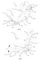
- the load-bearing structure 5 is rotatable relative to the frame 2 about said main axis of rotation between a transport position and a plurality of tipping positions. It should be noticed that in the transport position (see Figures 1 and 2 ) the load-bearing structure 5 is substantially close to the frame 2. In contrast, in the tipping positions (see Figures 6 , 8 and 13 ) the load-bearing structure 5 is partly distanced from the frame 2 and is at an angle relative to when it is in the transport position.
- the main axis of rotation is substantially perpendicular to the direction of movement of the truck 1 in the case of bodies 3 which tip backwards.
- the load-bearing structure 5 may also be rotatable about two or more main axes of rotation, in use substantially parallel with the direction of movement of the truck 1, for trucks 3 which also have lateral tipping (three-sided tipping trucks).
- the body 3 also comprises a loading bed 6 (partly visible in Figure 1 ) mounted on the load-bearing structure 5. In use, the materials and/or tools which are loaded on the body 3 rest on said loading bed 6.
- the loading bed 6 has four sides 7. At least one of the four sides 7 is an unloading side 8 (see Figure 1 ). The latter is positioned substantially close to the main axis of rotation and is parallel with said main axis of rotation.
- the loading bed 6 when the load-bearing structure 5 is in the transport position, the loading bed 6 is substantially in a lowered configuration (see Figures 1 and 2 ) to allow, in use, the transportation of materials and tools contained in the body 3 (more precisely, positioned on the loading bed 6).
- the loading bed 6 In the lowered configuration, the loading bed 6 is advantageously parallel with a surface on which the truck 1 is, in use, positioned.
- the loading bed 6 is substantially horizontal when the load-bearing structure is in the transport position (and therefore the loading bed 6 is in the lowered configuration) and the truck 1 rests on flat ground.
- the loading bed 6 is in a configuration set at an angle relative to when it is in the lowered configuration. It should be noticed that, thanks to a tipping of the body 3, it is preferably possible, in use, to unload from the body 3 loose materials such as sand, gravel and other aggregates.
- the body 3 further comprises at least four side boards 9, one of which is a front side board 9, close to the cab of the truck 1, one is a rear side board 9, opposite to the front side board 9 and distanced from the cab, and two are lateral side boards 9 opposite one another and positioned between the front side board 9 and the rear side board 9.
- Each side board 9 is associated with one of the sides 7 of the loading bed 6.
- the side boards 9 there are one or more uprights 11 of the load-bearing structure 5 and the side boards 9 are associated with said uprights 11 (see Figures 1 and 2 ).
- the uprights 11 are not present and that the side boards 9 may be associated directly with one another.
- At least the side board 9 positioned at the unloading side 8 is an openable side board 10.
- the openable side board 10 advantageously coincides with the rear side board 9 (therefore, the unloading side 8 is positioned in the rear part 4 of the body 3) and the body 3 may be tipped backwards towards the rear part 4 of the body 3 (the front part of the body 3 is therefore distanced from the frame 2).
- the openable side board 10 may coincide with one of the opposite side boards 9 positioned between the front side board 9 and the rear side board 9 and the body 3 may be tipped sideways towards one side of the truck 1.
- the loading bed 6 comprises two or more unloading sides 8 and the body 3 must comprise more than one openable side board 10, each associated with one of the loading sides 8.
- the openable side board 10 comprises a base portion 12 and a top portion 13 (see Figures 1 and 2 ). Both the base portion 12 and the top portion 13 are independently rotatably couplable to the load-bearing structure 5.
- the openable side board 10 has dual opening modes.
- the first opening mode (see Figures 10 and 11 ) comprises uncoupling of the top portion 13 of the load-bearing structure 5 and tipping of the openable side board 10 downwards (the top portion 13 is positioned below the base portion 12).
- the second opening mode comprises uncoupling of the base portion 12 from the load-bearing structure 5 and an oscillation of the openable side board 10 relative to the load-bearing structure 5 (see Figures 7 and 8 ).
- the openable side board 10 is movable between a closed position (see Figures 1 and 2 ) and a plurality of first open positions (see Figures 10 , 11 , 12 and 13 ); whilst in accordance with the second opening mode, the openable side board 10 is movable between said closed position and a plurality of second open positions (see Figures 7 and 8 ) which are different from the first open positions.
- the openable side board 10 closes the body 3 and is positioned substantially perpendicularly to the loading bed 6 with the base portion 12 adjacent to the loading bed 6. Therefore, advantageously, the top portion 13 is positioned substantially above the base portion 12 when the openable side board 10 is in the closed position and the truck 1 is, in use, positioned on a substantially horizontal surface.
- the openable side board 10 can move from said closed position (see Figures 1 and 2 ) to the first open positions (see Figures 10 , 11 , 12 and 13 ) by means of a rotation about a first axis of rotation.
- Said first axis of rotation is substantially parallel with the unloading side 8 and substantially adjacent to the base portion 12.
- the top portion 13 is positioned substantially on opposite sides relative to a plane defined by the loading bed 6, when the openable side board 10 is in the closed position and in the first open positions.
- the top portion 13 and the base portion 12 are substantially vertically aligned and the top portion 13 is positioned substantially below the base portion 12.
- the top portion 13 may be manually dissociated from the load-bearing structure 5 (as explained in more detail below) to advantageously allow, in use, the operators to easily climb onto the loading bed 6 and to manually unload the various types of objects contained in the body 3.
- the openable side board 10 may also move from the closed position (see Figures 1 and 2 ) to the second open positons (see Figures 7 and 8 ) by a rotation about a second axis of rotation substantially parallel with the unloading side 8 and substantially adjacent to the top portion 13.
- the base portion 12 is further from the loading bed 6 when the openable side board 10 is in the second open positions than when the openable side board 10 is in the closed position. Moreover, even in the second open positions, the base portion 12 and the top portion 13 are substantially vertically aligned when, in use, the truck 1 is positioned on a substantially horizontal surface (but, unlike the first open positions, there is no inversion of the position of the top portion 13 and the base portion 12 relative to one another compared with their positions relative to one another when the openable side board 10 is in the closed position).
- the base portion 12 can be automatically uncoupled from the load-bearing structure 5 (as explained in more detail below) following tipping of the body 3.
- the body 3 also comprises first constraining means 14, for constraining the base portion 12 to the load-bearing structure 5 rotatably about the first axis of rotation.
- said first constraining means 14 substantially hold the base portion 12 coupled to the load-bearing structure 5 when the openable side board 10 is in the first open positions, and substantially leave the base portion 12 free to uncouple from the load-bearing structure 5 when the openable side board 10 is in the closed position.
- the first constraining means 14 identify the first axis of rotation. The first constraining means 14 are described in more detail below.
- the body 3 also comprises second constraining means 15 for selectively constraining the top portion 13 to the load-bearing structure 5 rotatably about the second axis of rotation.
- the second constraining means 15 identify the second axis of rotation.
- the second constraining means 15 advantageously comprise at least two fixing bodies 16 and at least two elongate elements 17, one set of said parts being fixed to the load-bearing structure 5 of the body 3 and the other fixed to the openable side board 10 (see Figures 10 and 11 ).
- each fixing body 16 is advantageously fixed to one of the uprights 11 of the load-bearing structure 5, but in other embodiments it is also possible that the fixing bodies 16 are fixed to the side boards 9 adjacent to the openable side board 10 (in particular in the case in which the body 3 comprises a single openable side board 10 and the uprights 11 are not present).
- each fixing body 16 in the embodiment illustrated, comprises a first seat 18, in which the elongate element 17 is insertable, and comprises a movable part 19, movable between a locking position and an unlocking position.
- first seat 18 in which the elongate element 17 is insertable
- movable part 19 movable between a locking position and an unlocking position.
- the elongate element 17 is substantially locked in said first seat 18 (the top portion 13 is coupled to the load-bearing structure 5).
- the movable part 19 advantageously moves between the locking position and the unlocking position, in use, by means of a manual operation by an operator.
- the second constraining means 15 are in any case of the known type and therefore are not described in further detail herein.
- the second constraining means 15 are in however of a different type, provided that they are suitable for the purpose.
- the body 3 further comprises coupling means 20, mounted on the load-bearing structure 5 and associated with the base portion 12.
- Said coupling means 20 hold the base portion 12 coupled to the load-bearing structure 5 at least when the openable side board 10 is in the closed position and the load-bearing structure 5 is in one of the tipping positions but is set at an angle which is less than a predetermined reference angle ⁇ 0 relative to when it is in the transport position (see Figures 5 and 6 ).
- the coupling means 20 allow uncoupling of the base portion 12 from the load-bearing structure 5 at least when the load-bearing structure 5 is angled at said predetermined reference angle ⁇ 0 relative to when it is in the transport position (see Figures 7 and 8 ).
- the coupling means 20 are designed to hold the base portion 12 coupled to the load-bearing structure 5 even when the load-bearing structure 5 is in one of the tipping positions and is set at an angle relative to when it is in the transport position which is greater than the predetermined reference angle ⁇ 0 by at least a predetermined value.
- the coupling means 20 allow uncoupling of the base portion 12 from the load-bearing structure 5 when the load-bearing structure 5 is angled, relative to when it is in the transport position, at an angle between the predetermined reference angle ⁇ 0 and the predetermined reference angle ⁇ 0 plus the predetermined value.
- these advantageously comprise supporting means 21, sustaining means 22 and associating means 23.
- the supporting means 21 are mounted on the load-bearing structure 5 and fixed to the load-bearing structure 5 (see Figures 3 , 17 and 18 ) for supporting the openable side board 10.
- the sustaining means 22 are mounted on the base portion 12, fixed to the base portion 12 and couplable to the supporting means 21.
- the supporting means 21 and the sustaining means 22 comprise, one set at least one supporting element 24, and the other at least one pin 25.
- the supporting means 21 comprise at least one supporting element 24 and the sustaining means 22 comprise at least one pin 25 (see Figures 3, 4 , 18 and 19 ).
- the supporting means 21 comprise at least one pin 25 and that the sustaining means 22 comprise at least one supporting element 24 (solution not illustrated).
- the supporting means 21 comprise a plurality of supporting elements 24 for each pin 25.
- Each supporting element 24 projects relative to the load-bearing structure 5 and is substantially constituted of a first fork 26 having a "C" shape, comprising two prongs 27 spaced and parallel with one another and having a second seat 28 in which the pin 25 is insertable (see Figures 17 and 18 ).
- the supporting means 21 may be of a different type and the supporting element 24 may have different shapes provided that they are suitable for the purpose.
- the pin 25 extends substantially according to a longitudinal axis of extension and is couplable to the supporting element 24 rotatably about the first axis of rotation.
- the pin 25 is also substantially free to uncouple from the supporting element 24 according to a releasing direction when the openable side board 10 is in the closed position. It should be noticed that, in the embodiment illustrated, said releasing direction is substantially orthogonal to the longitudinal axis of extension of the pin 25 (more precisely it extends along an arc of a circle centred on the second axis of rotation).
- the pin 25 has a circular cross-section perpendicularly to the longitudinal axis of extension (see Figures 3 and 7 ).
- the base portion 12 of the openable side board 10 comprises, at the pin 25, one or more brackets 29 (two in the accompanying drawings) fixed to the base portion 12, projecting relative to the base portion 12 and elongate along a direction of extension substantially perpendicular to the first axis of rotation when the load-bearing structure 5 is in the closing position (see Figures 3 and 4 ).
- the pin 25 is advantageously fixed to the bracket or brackets 29.
- the base portion 12 may comprise at least a third seat in which the pin 25 fixed to the base portion 12 is inserted (solution not illustrated).
- the supporting element 24 must be of a different type to that of the embodiment illustrated (for example the supporting element 24 must be more elongate to guarantee sufficient free space for the openable side board 10 to be able to rotate about the first axis of rotation).
- the associating means 23 are operatively associable with the sustaining means 22 for holding the sustaining means 22 coupled to the supporting means 21 when the openable side board 10 is in the first open positions, and for substantially leaving the sustaining means 22 free to uncouple from the supporting means 21 when the openable side board 10 is in the closed position.
- the associating means 23 comprise at least a locking element 30, comprising an end part 31, and at least a shaped body 32 (see Figures 3 , 18 and 19 ).
- the locking element 30 and the shaped body 32 are associated one with the load-bearing structure 5 and the other with the base portion 12.
- the locking element 30 is associated with the load-bearing structure 5, whilst the shaped body 32 is associated with the base portion 12 of the openable side board 10.
- the locking element 30 may be associated with the base portion 12 and the shaped body 32 may be associated with the load-bearing structure 5 (solution not illustrated).
- the shaped body 32 and the end part 31 are substantially aligned with one another in a plane perpendicular to the first axis of rotation according to the releasing direction at least when the openable side board 10 is in the first open positions, substantially to prevent reciprocal movement of the end part 31 and of the shaped body 32 along the releasing direction and to hold the base portion 12 coupled to the load-bearing structure 5 (see Figure 19 ).
- the shaped body 32 and the end part 31 are substantially out of alignment with one another relative to the releasing direction when the openable side board 10 is in the closed position, substantially to allow reciprocal movement of the end part 31 relative to the shaped body 32 along the releasing direction and to substantially leave the base portion 12 free to uncouple from the load-bearing structure 5 (see Figure 4 ).
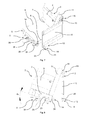
- the pin 25 comprises the shaped body 32 and a recess 33 made at the shaped body 32 (see Figures 3, 4 , 18 and 19 ).
- the shaped body 32 is obtained by creating the recess 33 in the lateral surface of the pin 25, which comprises, in a plane perpendicular to the longitudinal axis of extension and passing through the shaped body 32 and through the recess 33, a cross-section constituted of a circular segment with a base identifying the shaped body 32.
- the shaped body 32 advantageously extends eccentrically relative to the longitudinal axis of extension of the pin 25.
- the end part 31 and the recess 33 are substantially aligned with one another in the plane perpendicular to the first axis of rotation according to the releasing direction (and the shaped body 32 and the end part 31 are in contrast substantially out of alignment with one another relative to the releasing direction) when the openable side board 10 is in the closed position (see Figures 3 and 4 ).
- the end part 31 may therefore pass through the recess 33 when the openable side board 10 moves from the closed position towards the second open positions, in such a way as to allow substantially the reciprocal movement of the end part 31 relative to the shaped body 32 along the releasing direction and to leave the base portion 12 substantially free to uncouple from the load-bearing structure 5.
- the end part 31 and the recess 33 are substantially out of alignment with one another relative to the releasing direction (and the shaped body 32 and the end part 31 are substantially aligned with one another in a plane perpendicular to the first axis of rotation according to the releasing direction) at least when the openable side board 10 is in the first open positions, substantially to prevent the reciprocal movement of the end part 31 relative to the shaped body 32 along the releasing direction and to hold the base portion 12 coupled to the load-bearing structure 5 (see Figure 19 ).
- At least one shaped body 32 is in contrast associated with the pin 25 using other methods, provided that they are suitable for the purpose.
- the shaped body 32 may be fixed to the bracket or brackets 29 of the pin 25 (solution not illustrated).
- the locking element 30 forms a single body 34 with the supporting element 24 (see Figure 17 ).
- the single body 34 has, perpendicularly to the first axis of rotation, a "C" shaped with two ends 35. One of said ends 35 projects towards the other and constitutes the end part 31 of the locking element 30 (see Figure 17 ).
- the single body 34 forms, inside the "C" shape, a housing 36 in which the pin 25 is rotatably and slidably insertable, and extractable according to the releasing direction when the openable side board 10 is in the closed position (see Figure 17 ).
- the locking element 30 and the supporting element 24 may be constituted of two separate bodies.
- the locking element 30 may have the "C" shape described above and may be positioned adjacent to the supporting element 24, or it may be constituted of an elongate element projecting relative to the load-bearing structure 5 and with the end part 31 substantially close to the supporting element 24 and alignable and misalignable relative to the shaped body 32 (solutions not illustrated).
- the supporting means 21 and the sustaining means 22 comprise, one set at least two supporting elements 24, and the other at least two pin 25.
- the supporting means 21 comprise at least two supporting elements 24, spaced from one another
- the sustaining means 22 comprise at least two pins 25, spaced from one another and each couplable to one of the two supporting elements 24.
- the associating means 23 comprise at least two locking elements 30 and at least two shaped bodies 32, one for each pin 25.
- the supporting means 21 comprise a first supporting element 24, a second supporting element 24, which forms a first single body 34 with one of the two locking elements 30 (see Figure 17 ), a third supporting element 24 (similar to the first supporting element 24) and a fourth supporting element 24 (similar to the second supporting element 24), which forms a second single body 34 with the other of the two locking elements 30.
- the first supporting element 24 and the first single body 34 are advantageously substantially adjacent to one another.
- the third supporting element 24 and the second single body 34 are substantially adjacent to one another and spaced from the first supporting element 24 and from the first single body 34.
- first supporting element 24 and the first single body 34 form a first single part 37 (see Figure 17 ) and, similarly, the second supporting element 24 and the second single body 34 for a second single part 37.
- each single part 37 seen from above has a "C" shape (see Figure 17 ).
- one of the two pins 25 is couplable to the first single part 37 and the other of the two pins 25 is couplable to the second single part 37.
- these comprise a lever 38, operatively associated with the frame 2 and with the first constraining means 14.
- Said lever 38 is mounted on the load-bearing structure 5 rotatably about a secondary axis of rotation substantially parallel with the first axis of rotation.
- the coupling means 20 also comprise a contact element 39, fixed to the frame 2 (see Figures 1, 2 , 20 and 22 ).
- the contact element 39 comprises a first protuberance 40 facing towards the loading bed 6 (upwards when in use the truck 1 lies in a substantially horizontal plane).
- the lever 38 comprises a first arm 41 and a second arm 42 (see Figure 20 ).
- the first arm 41 is operatively associated with the contact element 39 (in particular at the top of the contact element 39 when in use the truck 1 lies in a substantially horizontal plane) and the second arm 42 is in contrast operatively associated with the pin 25 (advantageously not at the shaped body 32 and the recess 33).
- the first arm 41 interacts with the contact element 39, depending on the position of the load-bearing structure 5, for determining a rotation of the lever 38 about the secondary axis of rotation.
- the lever 38 can rotate, about said secondary axis of rotation, between a plurality of initial positions and at least a final position.
- the second arm 42 holds the base portion 12 coupled to the load-bearing structure 5 when the openable side board 10 is in the closed position and the load-bearing structure 5 is in one of the tipping positions and is set at an angle which is less than a predetermined reference angle ⁇ 0 relative to when it is in the transport position (see Figures 5 and 6 ).
- the second arm 42 allows uncoupling of the base portion 12 from the load-bearing structure 5 at least when the load-bearing structure 5 is angled at the predetermined reference angle ⁇ 0 relative to when it is in the transport position (see Figures 7 and 8 ).
- the first arm 41 is substantially elongate and extends between a first connecting portion 43a, which is connected to the second arm 42 and is fixed to it, and a first cantilever portion 43b, close to which a second protuberance 44 is made which interacts with the first protuberance 40 of the contact element 39.
- the second arm 42 is substantially elongate (although not as long as the first arm 41) and extends between a second connecting portion 45a, which is connected to the first arm 41 and is fixed to it, and a second cantilever portion 45b, where a tooth 46 is made which is associated with the pin 25.
- the coupling means 20 comprise a cam mechanism constituted of the first protuberance 40 and the second protuberance 44.
- the first protuberance 40 and the second protuberance 44 each have a respective shape designed to cause a rotation of the lever 38 about the secondary axis of rotation depending on the position of the load-bearing structure 5.
- first protuberance 40 and the second protuberance 44 interact, causing a rotation of the lever 38 from one of the initial positions towards the final position, when the load-bearing structure 5 moves from the transport position to one of the tipping positions and is set at an angle which is less than the predetermined reference angle ⁇ 0 relative to when it is in the transport position.
- the second arm 42 in particular the tooth 46 holds at least partly closed the housing 36 in which the pin 25 is inserted (see Figure 6 ), therefore the latter cannot uncouple from the supporting element 24 (or from the supporting elements 24 if present).
- first protuberance 40 and the second protuberance 44 interact, causing a rotation of the lever 38 from one of the initial positions towards the final position, when the load-bearing structure 5 moves from the transport position to the tipping position in which it is set at the predetermined reference angle ⁇ 0 relative to when it is in the transport position.
- the second arm 42 opens the housing 36 in which the pin 25 is inserted (see Figure 8 ), therefore the latter is substantially free to uncouple from the supporting element 24 (or from the supporting elements 24 if present).
- the cam mechanism is made in such a way that, when the load-bearing structure 5 is in one of the tipping positions and is set at an angle relative to when it is in the transport position which is greater than the predetermined reference angle ⁇ 0 by at least the predetermined value, the second arm 42 is in one of its own initial positions.
- lever 38 and the contact element 39 may have different forms provided that they are suitable for the purpose.
- the load-bearing structure 5 comprises, close to the unloading side 8 and the lever 38, at least one opening 47 in which the second arm 42 is slidably inserted (see Figures 1 and 17 ).
- the coupling means 20 also comprise elastic means 48, associated with the lever 38 and with the load-bearing structure 5, for pushing the second arm 42 towards the contact element 39.
- the thrust applied by the elastic means 48 on the lever 38 guarantees that the first arm 41 remains substantially operatively associated with the contact element 39.
- the lever 38 when the lever 38 has reached the final position it can still rotate about the secondary axis of rotation (since the first arm 41 continues to interact with the contact element 39).
- the lever 38 may be located at least in a further position (see Figures 14 , 15 and 16 ) in which the second arm 42 (in particular the tooth 46) can in any case close the housing 36 (even if the pin 25 is no longer inserted in the housing 36 at that point).
- the lever 38 is in fact equipped with a handle 49 (see Figure 20 ), fixed to the lever 38, which can be used to manually operate the lever 38 making it rotate from one of the initial positions to the final position (irrespective of the position of the load-bearing structure 5) in such a way that the second arm 42 (in particular the tooth 46) opens the housing 36.
- a handle 49 see Figure 20
- the supporting means 21 and the sustaining means 22 comprise, one set at least two supporting elements 24, and the other at least two pins 25 and the associating means 23 comprise at least two locking elements 30 and at least two shaped bodies 32.
- the coupling means 20 advantageously comprise a rod 50, fixed to said lever 38, and a third arm 51, fixed to said rod 50 and distanced from the lever 38 (see Figure 21 ).
- the third arm 51 is advantageously aligned with the second arm 42 along the secondary axis of rotation and rotates about the secondary axis of rotation in such a way that it is synchronised with the second arm 42.
- the second arm 42 and the third arm 51 are operatively associated, one with a first of the pins 25 and the other with a second of the pins 25, on one hand for holding the base portion 12 coupled to the load-bearing structure 5 when the openable side board 10 is in the closed position and the load-bearing structure 5 is in one of the tipping positions and is set at an angle which is less than the predetermined reference angle ⁇ 0 relative to when it is in the transport position, and on the other hand for allowing uncoupling of the base portion 12 from the load-bearing structure 5 at least when the load-bearing structure 5 is set at said predetermined reference angle ⁇ 0 relative to when it is in the transport position.
- the reference angle ⁇ 0 is substantially between 15° and 20°. However, in other embodiments, it is also possible that it has a different value or that it is substantially within a different range.
- the coupling means 20 may be of a different type provided that they are suitable for the purpose (for example, they may comprise a cam mechanism). Therefore, in conclusion, in the preferred embodiment illustrated the top portion 13 can be manually associated with and dissociated from the load-bearing structure 5 (manual release and manual hooking of the top portion 13), whilst the base portion 12 is automatically dissociated from the base portion 12 (following tipping of the body 3) only when the top portion 13 is constrained to the load-bearing structure 5.
- This invention brings important advantages.
- the truck with tipping body according to this invention is not subject to any risk of accidental detachment of the openable side board during unloading operations.
- the openable side board cannot be damaged due to an accidental detachment during unloading operations.
- the base portion of the openable side board is automatically released from the load-bearing structure, after tipping of the body, only when the top portion is hooked to the load-bearing structure.
Landscapes
- Engineering & Computer Science (AREA)
- Transportation (AREA)
- Mechanical Engineering (AREA)
- Handcart (AREA)
- Analysing Materials By The Use Of Radiation (AREA)
- Vehicle Step Arrangements And Article Storage (AREA)
Abstract
Description
- This invention relates to a truck with tipping body.
- It is applied in trucks in which the body can be tipped (and for this purpose it is rotatably mounted on the frame of the truck) and comprises at least one openable side board with dual opening modes (that is to say, board tipping downwards or oscillating about the upper part).
- As is known, the body comprises a load-bearing structure, a loading bed mounted on the load-bearing structure and at least four side boards, at least one of which is openable.
- In fact, on a body of that type it is possible to load both tools (for example tools to be used on sites) and materials (for example loose materials such as sand, gravel and other aggregates) of various types.
- In particular, to allow unloading of the materials contained in the body, the latter can be tipped and therefore at least one of the side boards must be openable. In most cases the openable side board is the one positioned at the rear of the body (therefore, this invention is mainly for that case), but in some applications it may also be one of the boards positioned at the sides of the body. It should also be noticed that this invention may be applied both on bodies which have only backward tipping, and on bodies with multiple tipping (three-sided).
- In particular, the openable side board is positioned at the unloading side of the loading bed to, in use, allow unloading of the material transported. In the case of bodies with multiple (three-sided) tipping, in which the body may be tipped backwards or sideways, the body comprises multiple unloading sides. In that case this invention may be applied to all of the unloading sides or to only one of them.
- The openable side board comprises a base portion, hookable to the load-bearing structure close to the loading bed, and a top portion, hookable to the load-bearing structure and distanced from the base portion. The body also comprises constraining means for rotatably and independently constraining the base portion and the top portion to the load-bearing structure. The openable side board can be selectively released from the load-bearing structure either manually at the top portion or automatically at the base portion during tipping of the body. In fact, the body comprises coupling means which allow that automatic releasing. They keep the base portion hooked to the load-bearing structure as long as the body is tipped at an angle which is less than a predetermined angle and they allow the base portion to be released from the load-bearing structure when the body is angled at an angle equal to the predetermined angle. Said coupling means may comprise for example a lever associated with a cam mechanism. In particular, the cam mechanism is sized in such a way that, when the body is angled at the predetermined angle, the lever disengages from the base portion and leaves the base portion free to be released from the load-bearing structure.
- As already indicated, the openable side board may alternatively be releasable from the load-bearing structure at the top portion, for example to facilitate an operator climbing onto the body and the pickup of objects positioned on the loading bed.
- However, this prior art technology has several disadvantages.
- In particular, with the prior art bodies, the openable side board detaches from the body when it is released at the top portion and the body is tipped and angled at an angle at least equal to the predetermined angle.
- In fact, when the body is angled at said predetermined angle, the lever disengages from the base portion, leaving it free to be released from the load-bearing portion, irrespective of whether or not the top portion is hooked to the load-bearing structure (and if the top portion is released from the load-bearing structure, the openable side board detaches from the body).
- That accidental detachment during unloading operations may involve, first, several risks for the safety of operators who may be located close to said side board, since they may be injured by the board falling.
- Moreover, the detachment of the side board may cause damage to the board due to its impact on the ground.
- Furthermore, in some embodiments, once the body has exceeded the predetermined tipping angle, if the board has not detached from the rest of the body, it may be the lever itself which damages it due to the position of the various parts relative to one another.
- Consequently, in use it is not possible to tip the body with the openable side board open downwards.
- In this context the technical purpose which forms the basis of this invention is to provide a truck with tipping body which overcomes the above-mentioned disadvantages.
- In particular, the technical purpose of this invention it to provide a truck with tipping body for which there is no risk of accidental detachment of the openable side board during unloading operations.
- It is also the technical purpose of this invention to provide a truck with tipping body which guarantees greater safety for operators who work close to said truck.
- Finally, the technical purpose of this invention is to provide a truck with tipping body in which the openable side board cannot be damaged due to an accidental detachment during unloading operations.
- The technical purpose specified and the aims indicated are substantially achieved by a truck with tipping body as described in the appended claims. Further features and the advantages of this invention are more apparent in the detailed description of a preferred, non-limiting embodiment of a truck with tipping body illustrated in the accompanying drawings, in which:
-
Figure 1 is an axonometric view, partly in cross-section, of a detail of the body at an openable side board positioned in a closed configuration, and of the system for hooking the board to the rest of the body; -
Figure 2 is a side view of the detail ofFigure 1 ; -
Figure 3 is a partial view, not in cross-section, of the detail ofFigure 1 ; -
Figure 4 is a rear face view of the detail ofFigure 3 ; -
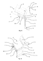
Figure 5 shows the detail of 1 in a first angled configuration; -
Figure 6 is a side view of the detail ofFigure 5 ; -
Figure 7 shows the detail of 1 in a first unloading position; -
Figure 8 is a side view of the detail ofFigure 7 ; -
Figure 9 is a partial view, not in cross-section, of the detail ofFigure 7 ; -
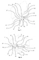
Figure 10 shows the detail ofFigure 1 in which the openable side board is in an open configuration; -
Figure 11 is a side view of the detail ofFigure 10 ; -
Figure 12 shows the detail ofFigure 10 in a second unloading position; -
Figure 13 is a side view of the detail ofFigure 12 ; -
Figure 14 shows the detail ofFigure 12 in a further unloading position; -
Figure 15 is a side view of the detail ofFigure 14 ; -
Figure 16 is a partial view, not in cross-section, of the detail ofFigure 14 ; -
Figure 17 shows only a part of the detail ofFigure 3 ; -
Figure 18 partly shows the detail ofFigure 3 but in which the openable side board is in the open configuration; -
Figure 19 is a rear face view of the detail ofFigure 18 ; -
Figure 20 is a cross-section of the detail ofFigure 19 according to the line XX - XX; -
Figure 21 is an axonometric whole view of another part of the body ofFigure 1 ; and -
Figure 22 is an axonometric view of a further detail of the body ofFigure 1 . - With reference to the accompanying drawings the numeral 1 denotes in its entirety a truck with tipping body according to this invention.
- It should be noticed that the accompanying drawings show only those parts of the truck 1 which are significant relative to this invention.
- It should also be noticed that this invention may be applied both to trucks 1 having
bodies 3 which can be tipped backwards and to trucks 1 havingbodies 3 which can also be tipped sideways (three-sided tipping bodies 3). - The truck 1 according to this invention comprises first a frame 2 (partly visible in the accompanying drawings), a cab (not visible in the accompanying drawings) mounted on the
frame 2 and a tippingbody 3 mounted on theframe 2. It should be noticed that, in use, thebody 3 is mounted on theframe 2 to the rear of the cab according to a direction of movement of the truck 1 on the road. - The
body 3 may be tipped by thrust means (not visible in the accompanying drawings, but of the known type), for example an oil hydraulic cylinder, to allow, in use, unloading of the materials contained in thebody 3. - The
body 3 comprises a front part (not visible in the accompanying drawings), substantially close to the cab of the truck 1, and a rear part 4 (partly visible inFigure 1 ), substantially distanced from the cab. -
Said body 3 comprises a load-bearingstructure 5, which is rotatably mounted on theframe 2 of the truck 1 according to a main axis of rotation. The load-bearingstructure 5 is rotatable relative to theframe 2 about said main axis of rotation between a transport position and a plurality of tipping positions. It should be noticed that in the transport position (seeFigures 1 and 2 ) the load-bearingstructure 5 is substantially close to theframe 2. In contrast, in the tipping positions (seeFigures 6 ,8 and13 ) the load-bearingstructure 5 is partly distanced from theframe 2 and is at an angle relative to when it is in the transport position. - It should be noticed that, in use, the main axis of rotation is substantially perpendicular to the direction of movement of the truck 1 in the case of
bodies 3 which tip backwards. The load-bearing structure 5 may also be rotatable about two or more main axes of rotation, in use substantially parallel with the direction of movement of the truck 1, fortrucks 3 which also have lateral tipping (three-sided tipping trucks). - The
body 3 also comprises a loading bed 6 (partly visible inFigure 1 ) mounted on the load-bearing structure 5. In use, the materials and/or tools which are loaded on thebody 3 rest on saidloading bed 6. - The
loading bed 6 has foursides 7. At least one of the foursides 7 is an unloading side 8 (seeFigure 1 ). The latter is positioned substantially close to the main axis of rotation and is parallel with said main axis of rotation. - It should also be noticed that, when the load-
bearing structure 5 is in the transport position, theloading bed 6 is substantially in a lowered configuration (seeFigures 1 and 2 ) to allow, in use, the transportation of materials and tools contained in the body 3 (more precisely, positioned on the loading bed 6). In the lowered configuration, theloading bed 6 is advantageously parallel with a surface on which the truck 1 is, in use, positioned. In particular, in the embodiment illustrated, in use, theloading bed 6 is substantially horizontal when the load-bearing structure is in the transport position (and therefore theloading bed 6 is in the lowered configuration) and the truck 1 rests on flat ground. - In contrast, when the load-
bearing structure 5 is in the tipping positions, theloading bed 6 is in a configuration set at an angle relative to when it is in the lowered configuration. It should be noticed that, thanks to a tipping of thebody 3, it is preferably possible, in use, to unload from thebody 3 loose materials such as sand, gravel and other aggregates. - The
body 3 further comprises at least fourside boards 9, one of which is afront side board 9, close to the cab of the truck 1, one is arear side board 9, opposite to thefront side board 9 and distanced from the cab, and two arelateral side boards 9 opposite one another and positioned between thefront side board 9 and therear side board 9. - Each
side board 9 is associated with one of thesides 7 of theloading bed 6. - In the embodiment illustrated, between the side boards 9 (at least between the
rear side board 9 and the twoopposite side boards 9 positioned between thefront side board 9 and the rear side board 9) there are one or more uprights 11 of the load-bearing structure 5 and theside boards 9 are associated with said uprights 11 (seeFigures 1 and 2 ). However, in other embodiments, it is also possible that theuprights 11 are not present and that theside boards 9 may be associated directly with one another. - At least the
side board 9 positioned at the unloadingside 8 is anopenable side board 10. - In the embodiment illustrated, the
openable side board 10 advantageously coincides with the rear side board 9 (therefore, the unloadingside 8 is positioned in therear part 4 of the body 3) and thebody 3 may be tipped backwards towards therear part 4 of the body 3 (the front part of thebody 3 is therefore distanced from the frame 2). However, in other embodiments, theopenable side board 10 may coincide with one of theopposite side boards 9 positioned between thefront side board 9 and therear side board 9 and thebody 3 may be tipped sideways towards one side of the truck 1. - However, it should be noticed that when the
body 3 may also be tipped sideways towards at least one of theopposite side boards 9 positioned between thefront side board 9 and therear side board 9, theloading bed 6 comprises two ormore unloading sides 8 and thebody 3 must comprise more than oneopenable side board 10, each associated with one of the loading sides 8. - The
openable side board 10 comprises abase portion 12 and a top portion 13 (seeFigures 1 and 2 ). Both thebase portion 12 and thetop portion 13 are independently rotatably couplable to the load-bearing structure 5. - In fact, the
openable side board 10 has dual opening modes. The first opening mode (seeFigures 10 and11 ) comprises uncoupling of thetop portion 13 of the load-bearing structure 5 and tipping of theopenable side board 10 downwards (thetop portion 13 is positioned below the base portion 12). In contrast, the second opening mode comprises uncoupling of thebase portion 12 from the load-bearing structure 5 and an oscillation of theopenable side board 10 relative to the load-bearing structure 5 (seeFigures 7 and 8 ). - In accordance with the first opening mode, the
openable side board 10 is movable between a closed position (seeFigures 1 and 2 ) and a plurality of first open positions (seeFigures 10 ,11 ,12 and13 ); whilst in accordance with the second opening mode, theopenable side board 10 is movable between said closed position and a plurality of second open positions (seeFigures 7 and 8 ) which are different from the first open positions. - In particular, in the closed position (see
Figures 1 and 2 ), theopenable side board 10 closes thebody 3 and is positioned substantially perpendicularly to theloading bed 6 with thebase portion 12 adjacent to theloading bed 6. Therefore, advantageously, thetop portion 13 is positioned substantially above thebase portion 12 when theopenable side board 10 is in the closed position and the truck 1 is, in use, positioned on a substantially horizontal surface. - The
openable side board 10 can move from said closed position (seeFigures 1 and 2 ) to the first open positions (seeFigures 10 ,11 ,12 and13 ) by means of a rotation about a first axis of rotation. Said first axis of rotation is substantially parallel with the unloadingside 8 and substantially adjacent to thebase portion 12. - It should be highlighted that the
top portion 13 is positioned substantially on opposite sides relative to a plane defined by theloading bed 6, when theopenable side board 10 is in the closed position and in the first open positions. In particular, in the first open positions when the truck 1 is, in use, positioned on a substantially horizontal surface, thetop portion 13 and thebase portion 12 are substantially vertically aligned and thetop portion 13 is positioned substantially below thebase portion 12. - It should be noticed that, in the preferred embodiment illustrated, the
top portion 13 may be manually dissociated from the load-bearing structure 5 (as explained in more detail below) to advantageously allow, in use, the operators to easily climb onto theloading bed 6 and to manually unload the various types of objects contained in thebody 3. - The
openable side board 10 may also move from the closed position (seeFigures 1 and 2 ) to the second open positons (seeFigures 7 and 8 ) by a rotation about a second axis of rotation substantially parallel with the unloadingside 8 and substantially adjacent to thetop portion 13. - It should be highlighted that the
base portion 12 is further from theloading bed 6 when theopenable side board 10 is in the second open positions than when theopenable side board 10 is in the closed position. Moreover, even in the second open positions, thebase portion 12 and thetop portion 13 are substantially vertically aligned when, in use, the truck 1 is positioned on a substantially horizontal surface (but, unlike the first open positions, there is no inversion of the position of thetop portion 13 and thebase portion 12 relative to one another compared with their positions relative to one another when theopenable side board 10 is in the closed position). - It should be noticed that, in the preferred embodiment illustrated, the
base portion 12 can be automatically uncoupled from the load-bearing structure 5 (as explained in more detail below) following tipping of thebody 3. - The
body 3 also comprises first constrainingmeans 14, for constraining thebase portion 12 to the load-bearing structure 5 rotatably about the first axis of rotation. - In particular, said first constraining
means 14 substantially hold thebase portion 12 coupled to the load-bearing structure 5 when theopenable side board 10 is in the first open positions, and substantially leave thebase portion 12 free to uncouple from the load-bearing structure 5 when theopenable side board 10 is in the closed position. In the embodiment illustrated, the first constrainingmeans 14 identify the first axis of rotation. The first constrainingmeans 14 are described in more detail below. - The
body 3 also comprises second constrainingmeans 15 for selectively constraining thetop portion 13 to the load-bearing structure 5 rotatably about the second axis of rotation. In the embodiment illustrated, the second constrainingmeans 15 identify the second axis of rotation. - The second constraining means 15 advantageously comprise at least two fixing
bodies 16 and at least twoelongate elements 17, one set of said parts being fixed to the load-bearing structure 5 of thebody 3 and the other fixed to the openable side board 10 (seeFigures 10 and11 ). - In the embodiment illustrated, each fixing
body 16 is advantageously fixed to one of theuprights 11 of the load-bearing structure 5, but in other embodiments it is also possible that the fixingbodies 16 are fixed to theside boards 9 adjacent to the openable side board 10 (in particular in the case in which thebody 3 comprises a singleopenable side board 10 and theuprights 11 are not present). - In the known way, each fixing
body 16, in the embodiment illustrated, comprises afirst seat 18, in which theelongate element 17 is insertable, and comprises amovable part 19, movable between a locking position and an unlocking position. In particular, when theelongate element 17 is inserted in thefirst seat 18 and themovable part 19 is in the locking position, theelongate element 17 is substantially locked in said first seat 18 (thetop portion 13 is coupled to the load-bearing structure 5). In contrast, when theelongate element 17 is inserted in thefirst seat 18 and themovable part 19 is in the unlocking positon, theelongate element 17 is substantially free to come out of the first seat 18 (thetop portion 13 is substantially free to uncouple from the load-bearing structure 5). It should be noticed that, in the preferred embodiment illustrated, themovable part 19 advantageously moves between the locking position and the unlocking position, in use, by means of a manual operation by an operator. The second constrainingmeans 15 are in any case of the known type and therefore are not described in further detail herein. - In other embodiments, it is also possible that the second constraining
means 15 are in however of a different type, provided that they are suitable for the purpose. - The
body 3 further comprises coupling means 20, mounted on the load-bearing structure 5 and associated with thebase portion 12. Said coupling means 20 hold thebase portion 12 coupled to the load-bearing structure 5 at least when theopenable side board 10 is in the closed position and the load-bearing structure 5 is in one of the tipping positions but is set at an angle which is less than a predetermined reference angle α0 relative to when it is in the transport position (seeFigures 5 and 6 ). Moreover, the coupling means 20 allow uncoupling of thebase portion 12 from the load-bearing structure 5 at least when the load-bearing structure 5 is angled at said predetermined reference angle α0 relative to when it is in the transport position (seeFigures 7 and 8 ). Moreover, in the preferred embodiment, the coupling means 20 are designed to hold thebase portion 12 coupled to the load-bearing structure 5 even when the load-bearing structure 5 is in one of the tipping positions and is set at an angle relative to when it is in the transport position which is greater than the predetermined reference angle α0 by at least a predetermined value. In other words, in this embodiment the coupling means 20 allow uncoupling of thebase portion 12 from the load-bearing structure 5 when the load-bearing structure 5 is angled, relative to when it is in the transport position, at an angle between the predetermined reference angle α0 and the predetermined reference angle α0 plus the predetermined value. - Returning to the first constraining
means 14, these advantageously comprise supportingmeans 21, sustainingmeans 22 and associatingmeans 23. - The supporting means 21 are mounted on the load-
bearing structure 5 and fixed to the load-bearing structure 5 (seeFigures 3 ,17 and 18 ) for supporting theopenable side board 10. - In contrast, the sustaining
means 22 are mounted on thebase portion 12, fixed to thebase portion 12 and couplable to the supportingmeans 21. - Preferably, the supporting
means 21 and the sustainingmeans 22 comprise, one set at least one supportingelement 24, and the other at least onepin 25. In general, advantageously, the supportingmeans 21 comprise at least one supportingelement 24 and the sustainingmeans 22 comprise at least one pin 25 (seeFigures 3, 4 ,18 and19 ). However, in other embodiments it is also possible that the supportingmeans 21 comprise at least onepin 25 and that the sustainingmeans 22 comprise at least one supporting element 24 (solution not illustrated). - Preferably, the supporting
means 21 comprise a plurality of supportingelements 24 for eachpin 25. Each supportingelement 24 projects relative to the load-bearing structure 5 and is substantially constituted of afirst fork 26 having a "C" shape, comprising twoprongs 27 spaced and parallel with one another and having asecond seat 28 in which thepin 25 is insertable (seeFigures 17 and 18 ). However, in other embodiments, the supportingmeans 21 may be of a different type and the supportingelement 24 may have different shapes provided that they are suitable for the purpose. In the embodiment illustrated, thepin 25 extends substantially according to a longitudinal axis of extension and is couplable to the supportingelement 24 rotatably about the first axis of rotation. Thepin 25 is also substantially free to uncouple from the supportingelement 24 according to a releasing direction when theopenable side board 10 is in the closed position. It should be noticed that, in the embodiment illustrated, said releasing direction is substantially orthogonal to the longitudinal axis of extension of the pin 25 (more precisely it extends along an arc of a circle centred on the second axis of rotation). - It should also be noticed that, in the embodiment illustrated, the
pin 25 has a circular cross-section perpendicularly to the longitudinal axis of extension (seeFigures 3 and7 ). - Moreover, in the embodiment illustrated, the
base portion 12 of theopenable side board 10 comprises, at thepin 25, one or more brackets 29 (two in the accompanying drawings) fixed to thebase portion 12, projecting relative to thebase portion 12 and elongate along a direction of extension substantially perpendicular to the first axis of rotation when the load-bearing structure 5 is in the closing position (seeFigures 3 and 4 ). Thepin 25 is advantageously fixed to the bracket orbrackets 29. - However, in other embodiments, the
base portion 12 may comprise at least a third seat in which thepin 25 fixed to thebase portion 12 is inserted (solution not illustrated). It should be noticed that, in the latter case, the supportingelement 24 must be of a different type to that of the embodiment illustrated (for example the supportingelement 24 must be more elongate to guarantee sufficient free space for theopenable side board 10 to be able to rotate about the first axis of rotation). According to the innovative aspect of this invention, the associatingmeans 23 are operatively associable with the sustainingmeans 22 for holding the sustaining means 22 coupled to the supportingmeans 21 when theopenable side board 10 is in the first open positions, and for substantially leaving the sustaining means 22 free to uncouple from the supportingmeans 21 when theopenable side board 10 is in the closed position. - In the embodiment illustrated, the associating
means 23 comprise at least a lockingelement 30, comprising anend part 31, and at least a shaped body 32 (seeFigures 3 ,18 and19 ). - In particular, the locking
element 30 and the shapedbody 32 are associated one with the load-bearing structure 5 and the other with thebase portion 12. Advantageously, in the embodiment illustrated, the lockingelement 30 is associated with the load-bearing structure 5, whilst the shapedbody 32 is associated with thebase portion 12 of theopenable side board 10. However, in other embodiments, the lockingelement 30 may be associated with thebase portion 12 and the shapedbody 32 may be associated with the load-bearing structure 5 (solution not illustrated). - The shaped
body 32 and theend part 31 are substantially aligned with one another in a plane perpendicular to the first axis of rotation according to the releasing direction at least when theopenable side board 10 is in the first open positions, substantially to prevent reciprocal movement of theend part 31 and of the shapedbody 32 along the releasing direction and to hold thebase portion 12 coupled to the load-bearing structure 5 (seeFigure 19 ). - In contrast, the shaped
body 32 and theend part 31 are substantially out of alignment with one another relative to the releasing direction when theopenable side board 10 is in the closed position, substantially to allow reciprocal movement of theend part 31 relative to the shapedbody 32 along the releasing direction and to substantially leave thebase portion 12 free to uncouple from the load-bearing structure 5 (seeFigure 4 ). - In the embodiment illustrated, the
pin 25 comprises the shapedbody 32 and arecess 33 made at the shaped body 32 (seeFigures 3, 4 ,18 and19 ). In particular, the shapedbody 32 is obtained by creating therecess 33 in the lateral surface of thepin 25, which comprises, in a plane perpendicular to the longitudinal axis of extension and passing through the shapedbody 32 and through therecess 33, a cross-section constituted of a circular segment with a base identifying the shapedbody 32. The shapedbody 32 advantageously extends eccentrically relative to the longitudinal axis of extension of thepin 25. - The
end part 31 and therecess 33 are substantially aligned with one another in the plane perpendicular to the first axis of rotation according to the releasing direction (and the shapedbody 32 and theend part 31 are in contrast substantially out of alignment with one another relative to the releasing direction) when theopenable side board 10 is in the closed position (seeFigures 3 and 4 ). Theend part 31 may therefore pass through therecess 33 when theopenable side board 10 moves from the closed position towards the second open positions, in such a way as to allow substantially the reciprocal movement of theend part 31 relative to the shapedbody 32 along the releasing direction and to leave thebase portion 12 substantially free to uncouple from the load-bearing structure 5. - In contrast, the
end part 31 and therecess 33 are substantially out of alignment with one another relative to the releasing direction (and the shapedbody 32 and theend part 31 are substantially aligned with one another in a plane perpendicular to the first axis of rotation according to the releasing direction) at least when theopenable side board 10 is in the first open positions, substantially to prevent the reciprocal movement of theend part 31 relative to the shapedbody 32 along the releasing direction and to hold thebase portion 12 coupled to the load-bearing structure 5 (seeFigure 19 ). - It should be noticed that, in other embodiments, it is also possible that at least one
shaped body 32 is in contrast associated with thepin 25 using other methods, provided that they are suitable for the purpose. For example the shapedbody 32 may be fixed to the bracket orbrackets 29 of the pin 25 (solution not illustrated). - In the preferred embodiment illustrated, the locking
element 30 forms asingle body 34 with the supporting element 24 (seeFigure 17 ). - In particular, the
single body 34 has, perpendicularly to the first axis of rotation, a "C" shaped with two ends 35. One of said ends 35 projects towards the other and constitutes theend part 31 of the locking element 30 (seeFigure 17 ). - Advantageously, the
single body 34 forms, inside the "C" shape, ahousing 36 in which thepin 25 is rotatably and slidably insertable, and extractable according to the releasing direction when theopenable side board 10 is in the closed position (seeFigure 17 ). - However, in other embodiments, the locking
element 30 and the supportingelement 24 may be constituted of two separate bodies. For example the lockingelement 30 may have the "C" shape described above and may be positioned adjacent to the supportingelement 24, or it may be constituted of an elongate element projecting relative to the load-bearing structure 5 and with theend part 31 substantially close to the supportingelement 24 and alignable and misalignable relative to the shaped body 32 (solutions not illustrated). - It should also be noticed that, in the preferred embodiment, the supporting
means 21 and the sustainingmeans 22 comprise, one set at least two supportingelements 24, and the other at least twopin 25. In particular, advantageously, the supportingmeans 21 comprise at least two supportingelements 24, spaced from one another, and the sustainingmeans 22 comprise at least twopins 25, spaced from one another and each couplable to one of the two supportingelements 24. Moreover, in the preferred embodiment illustrated, the associatingmeans 23 comprise at least two lockingelements 30 and at least twoshaped bodies 32, one for eachpin 25. - In the embodiment illustrated, the supporting
means 21 comprise a first supportingelement 24, a second supportingelement 24, which forms a firstsingle body 34 with one of the two locking elements 30 (seeFigure 17 ), a third supporting element 24 (similar to the first supporting element 24) and a fourth supporting element 24 (similar to the second supporting element 24), which forms a secondsingle body 34 with the other of the two lockingelements 30. The first supportingelement 24 and the firstsingle body 34 are advantageously substantially adjacent to one another. In contrast, the third supportingelement 24 and the secondsingle body 34 are substantially adjacent to one another and spaced from the first supportingelement 24 and from the firstsingle body 34. Advantageously, in the preferred embodiment illustrated, the first supportingelement 24 and the firstsingle body 34 form a first single part 37 (seeFigure 17 ) and, similarly, the second supportingelement 24 and the secondsingle body 34 for a secondsingle part 37. Advantageously, eachsingle part 37 seen from above has a "C" shape (seeFigure 17 ). - It should be noticed that one of the two
pins 25 is couplable to the firstsingle part 37 and the other of the twopins 25 is couplable to the secondsingle part 37. - Returning to the coupling means 20, in the embodiment illustrated, these comprise a
lever 38, operatively associated with theframe 2 and with the first constrainingmeans 14. Saidlever 38 is mounted on the load-bearing structure 5 rotatably about a secondary axis of rotation substantially parallel with the first axis of rotation. - In the embodiment illustrated, the coupling means 20 also comprise a
contact element 39, fixed to the frame 2 (seeFigures 1, 2 ,20 and22 ). In particular, thecontact element 39 comprises afirst protuberance 40 facing towards the loading bed 6 (upwards when in use the truck 1 lies in a substantially horizontal plane). - The
lever 38 comprises afirst arm 41 and a second arm 42 (seeFigure 20 ). Thefirst arm 41 is operatively associated with the contact element 39 (in particular at the top of thecontact element 39 when in use the truck 1 lies in a substantially horizontal plane) and thesecond arm 42 is in contrast operatively associated with the pin 25 (advantageously not at the shapedbody 32 and the recess 33). - The
first arm 41 interacts with thecontact element 39, depending on the position of the load-bearing structure 5, for determining a rotation of thelever 38 about the secondary axis of rotation. In fact, thelever 38 can rotate, about said secondary axis of rotation, between a plurality of initial positions and at least a final position. - In the initial positions the
second arm 42 holds thebase portion 12 coupled to the load-bearing structure 5 when theopenable side board 10 is in the closed position and the load-bearing structure 5 is in one of the tipping positions and is set at an angle which is less than a predetermined reference angle α0 relative to when it is in the transport position (seeFigures 5 and 6 ). In contrast, in the final position, thesecond arm 42 allows uncoupling of thebase portion 12 from the load-bearing structure 5 at least when the load-bearing structure 5 is angled at the predetermined reference angle α0 relative to when it is in the transport position (seeFigures 7 and 8 ). - In the embodiment illustrated, the
first arm 41 is substantially elongate and extends between a first connectingportion 43a, which is connected to thesecond arm 42 and is fixed to it, and afirst cantilever portion 43b, close to which asecond protuberance 44 is made which interacts with thefirst protuberance 40 of thecontact element 39. - Moreover, in the embodiment illustrated, the
second arm 42 is substantially elongate (although not as long as the first arm 41) and extends between a second connectingportion 45a, which is connected to thefirst arm 41 and is fixed to it, and asecond cantilever portion 45b, where atooth 46 is made which is associated with thepin 25. Advantageously, the coupling means 20 comprise a cam mechanism constituted of thefirst protuberance 40 and thesecond protuberance 44. Thefirst protuberance 40 and thesecond protuberance 44 each have a respective shape designed to cause a rotation of thelever 38 about the secondary axis of rotation depending on the position of the load-bearing structure 5. In particular, thefirst protuberance 40 and thesecond protuberance 44 interact, causing a rotation of thelever 38 from one of the initial positions towards the final position, when the load-bearing structure 5 moves from the transport position to one of the tipping positions and is set at an angle which is less than the predetermined reference angle α0 relative to when it is in the transport position. During that rotation of thelever 38, the second arm 42 (in particular the tooth 46) holds at least partly closed thehousing 36 in which thepin 25 is inserted (seeFigure 6 ), therefore the latter cannot uncouple from the supporting element 24 (or from the supportingelements 24 if present). - Moreover, the
first protuberance 40 and thesecond protuberance 44 interact, causing a rotation of thelever 38 from one of the initial positions towards the final position, when the load-bearing structure 5 moves from the transport position to the tipping position in which it is set at the predetermined reference angle α0 relative to when it is in the transport position. Following that rotation of thelever 38, the second arm 42 (in particular the tooth 46) opens thehousing 36 in which thepin 25 is inserted (seeFigure 8 ), therefore the latter is substantially free to uncouple from the supporting element 24 (or from the supportingelements 24 if present). - Moreover, in the preferred embodiment illustrated, the cam mechanism is made in such a way that, when the load-
bearing structure 5 is in one of the tipping positions and is set at an angle relative to when it is in the transport position which is greater than the predetermined reference angle α0 by at least the predetermined value, thesecond arm 42 is in one of its own initial positions. - However, it should be noticed that in other embodiments the
lever 38 and thecontact element 39 may have different forms provided that they are suitable for the purpose. - The load-
bearing structure 5 comprises, close to theunloading side 8 and thelever 38, at least oneopening 47 in which thesecond arm 42 is slidably inserted (seeFigures 1 and17 ). - In the embodiment illustrated, the coupling means 20 also comprise
elastic means 48, associated with thelever 38 and with the load-bearing structure 5, for pushing thesecond arm 42 towards thecontact element 39. The thrust applied by the elastic means 48 on thelever 38 guarantees that thefirst arm 41 remains substantially operatively associated with thecontact element 39. - It should be noticed that, in the embodiment illustrated, when the
lever 38 has reached the final position it can still rotate about the secondary axis of rotation (since thefirst arm 41 continues to interact with the contact element 39). In this case, if the load-bearing structure 5 is in a tipping position and is set at an angle relative to when it is in the transport position which is greater than the predetermined reference angle α0, thelever 38 may be located at least in a further position (seeFigures 14 ,15 and 16 ) in which the second arm 42 (in particular the tooth 46) can in any case close the housing 36 (even if thepin 25 is no longer inserted in thehousing 36 at that point). - It should be noticed that, in the embodiment illustrated, when the load-
bearing structure 5 moves from the tipping position, in which the load-bearing structure 5 is angled at the predetermined reference angle α0, towards the transport position, thelever 38 moves towards one of the initial positions, but thepin 25 cannot be automatically associated with the supportingelement 24 since thesecond arm 42 of thelever 38 closes thehousing 36 before thepin 25 can be inserted in it. Therefore, in this case, thepin 25 is associated with the supportingelement 24 after manual operation of thelever 38 to open the entrance to thehousing 36. For that purpose, thelever 38 is in fact equipped with a handle 49 (seeFigure 20 ), fixed to thelever 38, which can be used to manually operate thelever 38 making it rotate from one of the initial positions to the final position (irrespective of the position of the load-bearing structure 5) in such a way that the second arm 42 (in particular the tooth 46) opens thehousing 36. - In the preferred embodiment illustrated, as previously indicated, the supporting
means 21 and the sustainingmeans 22 comprise, one set at least two supportingelements 24, and the other at least twopins 25 and the associatingmeans 23 comprise at least two lockingelements 30 and at least twoshaped bodies 32. Moreover in the preferred embodiment illustrated, the coupling means 20 advantageously comprise arod 50, fixed to saidlever 38, and athird arm 51, fixed to saidrod 50 and distanced from the lever 38 (seeFigure 21 ). - In particular, the
third arm 51 is advantageously aligned with thesecond arm 42 along the secondary axis of rotation and rotates about the secondary axis of rotation in such a way that it is synchronised with thesecond arm 42. Thesecond arm 42 and thethird arm 51 are operatively associated, one with a first of thepins 25 and the other with a second of thepins 25, on one hand for holding thebase portion 12 coupled to the load-bearing structure 5 when theopenable side board 10 is in the closed position and the load-bearing structure 5 is in one of the tipping positions and is set at an angle which is less than the predetermined reference angle α0 relative to when it is in the transport position, and on the other hand for allowing uncoupling of thebase portion 12 from the load-bearing structure 5 at least when the load-bearing structure 5 is set at said predetermined reference angle α0 relative to when it is in the transport position. - In the preferred embodiment illustrated, the reference angle α0 is substantially between 15° and 20°. However, in other embodiments, it is also possible that it has a different value or that it is substantially within a different range.
- It should be noticed that, in other embodiments, the coupling means 20 may be of a different type provided that they are suitable for the purpose (for example, they may comprise a cam mechanism). Therefore, in conclusion, in the preferred embodiment illustrated the
top portion 13 can be manually associated with and dissociated from the load-bearing structure 5 (manual release and manual hooking of the top portion 13), whilst thebase portion 12 is automatically dissociated from the base portion 12 (following tipping of the body 3) only when thetop portion 13 is constrained to the load-bearing structure 5. - This invention brings important advantages.
- In fact, the truck with tipping body according to this invention is not subject to any risk of accidental detachment of the openable side board during unloading operations.
- The solution provided guarantees greater safety for operators working close to the truck, since they cannot be accidentally injured due to detachment of the openable side board.
- Moreover, with the solution provided, the openable side board cannot be damaged due to an accidental detachment during unloading operations. In fact, the base portion of the openable side board is automatically released from the load-bearing structure, after tipping of the body, only when the top portion is hooked to the load-bearing structure.
- Therefore, thanks to this invention it is possible to use tipping of the body without worrying even with a side board which is openable downwards. Finally, it should be noticed that this invention is relatively easy to produce and that even the cost linked to implementing the invention is not very high.
- The invention described above may be modified and adapted in several ways without thereby departing from the scope of the inventive concept. Moreover, all details of the invention may be substituted with other technically equivalent elements and the materials used, as well as the shapes and dimensions of the various components, may vary according to requirements.
Claims (13)
- A truck with tipping body comprising:a frame (2); anda tipping body (3) mounted on the frame (2);
said body (3) comprising:a load-bearing structure (5), rotatably mounted on the frame (2) according to a main axis of rotation, the load-bearing structure (5) being rotatable relative to the frame (2) about said main axis of rotation between a transport position, in which the load-bearing structure (5) is substantially close to the frame (2), and a plurality of tipping positions, in which the load-bearing structure (5) is partly distanced from the frame (2) and is set at an angle relative to when it is in the transport position;a loading bed (6), mounted on said load-bearing structure (5) and comprising an unloading side (8) substantially parallel with and close to said main axis of rotation;at least one openable side board (10), positioned at the unloading side (8) and comprising a base portion (12), rotatably couplable to the load-bearing structure (5), and a top portion (13), rotatably couplable to the load-bearing structure (5),
the openable side board (10) being mobile between a closed position,
in which the openable side board (10) closes the body (3) and is positioned substantially perpendicularly to the loading bed (6) with the base portion (12) adjacent to the loading bed (6), and a plurality of first open positions and between said closed position and a plurality of second open positions which are different from the first open positions;
the openable side board (10) being able to move from the closed position to the first open positions by a rotation about a first axis of rotation substantially parallel with said unloading side (8) and substantially adjacent to said base portion (12), the top portion (13) being positioned substantially on opposite sides relative to a plane defined by the loading bed (6) when the openable side board (10) is in the closed position and in the first open positions; the openable side board (10) being able to move from the closed position to the second open positions by a rotation about a second axis of rotation substantially parallel with said unloading side (8) and substantially adjacent to the top portion (13), the base portion (12) being further from the loading bed (6) when the openable side board (10) is in the second open positions than when the openable side board (10) is in the closed position;- first constraining means (14), for constraining the base portion (12) to the load-bearing structure (5) rotatably about said first axis of rotation; said first constraining means (14) substantially holding the base portion (12) coupled to the load-bearing structure (5) when the openable side board (10) is in the first open positions, and substantially leaving the base portion (12) free to uncouple from the load-bearing structure (5) when the openable side board (10) is in the closed position;- second constraining means (15), for selectively constraining the top portion (13) to the load-bearing structure (5) rotatably about the second axis of rotation; andcoupling means (20), mounted on the load-bearing structure (5) and associated with the base portion (12), for holding the base portion (12) coupled to the load-bearing structure (5) when the openable side board (10) is in the closed position and the load-bearing structure (5) is in one of the tipping positions and is set at an angle which is less than a predetermined reference angle a0 relative to when it is in the transport position, and for allowing uncoupling of the base portion (12) from the load-bearing structure (5) at least when the load-bearing structure (5) is set at said predetermined reference angle a0 relative to when it is in the transport position. - The truck according to claim 1, wherein said first constraining means (14) comprise:supporting means (21), mounted on the load-bearing structure (5) and fixed to the load-bearing structure (5), for supporting the openable side board (10);- sustaining means (22), mounted on the base portion (12), fixed to the base portion (12) and couplable to said supporting means (21); and- associating means (23), operatively associable with said sustaining means (22), for holding the sustaining means (22) coupled to the supporting means (21) when the openable side board (10) is in the first open positions, and for substantially leaving the sustaining means (22) free to uncouple from the supporting means (21) when the openable side board (10) is in the closed position.
- The truck according to claim 2, wherein said associating means (23) comprise at least a locking element (30), comprising an end part (31), and at least a shaped body (32), the locking element (30) and the shaped body (32) being associated one with the load-bearing structure (5) and the other with the base portion (12);
said shaped body (32) and said end part (31) being substantially aligned with one another in a plane perpendicular to the first axis of rotation according to a releasing direction at least when the openable side board (10) is in the first open positions, substantially to prevent reciprocal movement of the end part (31) and of the shaped body (32) along the releasing direction and to hold the base portion (12) coupled to the load-bearing structure (5);
said shaped body (32) and said end part (31) being substantially out of alignment with one another relative to the releasing direction when the openable side board (10) is in the closed position, substantially to allow reciprocal movement of the end part (31) relative to the shaped body (32) along the releasing direction and to substantially leave the base portion (12) free to uncouple from the load-bearing structure (5). - The truck according to claim 3, wherein said supporting means (21) and said sustaining means (22) comprise, one set at least one supporting element (24), and the other at least one pin (25), said pin (25) extending substantially according to a longitudinal axis of extension and being couplable to the supporting element (24) rotatably about said first axis of rotation,
the pin (25) being substantially free to uncouple from the supporting element (24) according to the releasing direction when the openable side board (10) is in the closed position; said releasing direction being substantially orthogonal to the longitudinal axis of extension. - The truck according to claims 3 and 4, wherein said pin (25) comprises said shaped body (32) and a recess (33) made at the shaped body (32), the end part (31) and the recess (33) being substantially aligned with one another in the plane perpendicular to the first axis of rotation according to the releasing direction when the openable side board (10) is in the closed position and the end part (31) being insertable in the recess (33) when the openable side board (10) moves from the closed position towards the second open positions.
- The truck according to claims 3 and 4 or 5, wherein the supporting element (24) and the locking element (30) form a single body (34).
- The truck according to claim 6, wherein said single body (34) has, perpendicularly to the first axis of rotation, a "C" shape with two ends (35), one of said ends (35) projecting towards the other and being constituted of said end part (31), the single body (34) forming inside the "C" shape a housing (36) in which said pin (25) is rotatably and slidably insertable and extractable according to said releasing direction when said shaped body (32) and said end part (31) are substantially not aligned with one another relative to said releasing direction.
- The truck according to any one of claims 4 to 7, wherein said supporting means (21) and said sustaining means (22) comprise, one set at least two supporting elements (24), and the other at least two pins (25) and the associating means (23) comprise at least two locking elements (30) and at least two shaped bodies (32).
- The truck according to any one of claims 4 to 8, wherein the coupling means (20) comprise a contact element (39), fixed to the frame (2), and a lever (38), operatively associated with the frame (2) and with the first constraining means (14), said lever (38) being mounted on the load-bearing structure (5) rotatably about a secondary axis of rotation substantially parallel with the first axis of rotation, said lever (38) comprising a first arm (41), operatively associated with said contact element (39), and a second arm (42), operatively associated with said pin (25),
the first arm (41) interacting with the contact element (39) depending on the position of the load-bearing structure (5) for determining a rotation of the lever (38) about said secondary axis of rotation between a plurality of initial positions, in which the second arm (42) holds the base portion (12) coupled to the load-bearing structure (5) when the openable side board (10) is in the closed position and the load-bearing structure (5) is in one of the tipping positions and is set at an angle which is less than the predetermined reference angle a0 relative to when it is in the transport position, and at least a final position, in which the second arm (42) allows uncoupling of the base portion (12) from the load-bearing structure (5) at least when the load-bearing structure (5) is set at said predetermined reference angle a0 relative to when it is in the transport position. - The truck according to claims 8 and 9, wherein the coupling means (20) comprise a rod (50), fixed to said lever (38), and a third arm (51), fixed to said rod (50) and distanced from the lever (38), the third arm (51) being aligned with the second arm (42) along the secondary axis of rotation and rotating about the secondary axis of rotation in a synchronised fashion with the second arm (42), the second arm (42) and the third arm (51) being operatively associated one with a first of said pins (25) and the other with a second of said pins (25) for holding the base portion (12) coupled to the load-bearing structure (5) when the openable side board (10) is in the closed position and the load-bearing structure (5) is in one of the tipping positions and is set at an angle which is less than the predetermined reference angle a0 relative to when it is in the transport position, and for allowing uncoupling of the base portion (12) from the load-bearing structure (5) at least when the load-bearing structure (5) is set at said predetermined reference angle a0 relative to when it is in the transport position.
- The truck according to claim 9 or 10, wherein said coupling means (20) also comprise elastic means (48), associated with the lever (38) and with the load-bearing structure (5), for pushing said first arm (41) towards the contact element (39).
- The truck according to any one of the preceding claims, characterised in that the coupling means (20) are designed to hold the base portion (12) coupled to the load-bearing structure (5) even when the load-bearing structure (5) is in one of the tipping positions and is set at an angle relative to when it is in the transport position which is greater than the predetermined reference angle a0 by at least a predetermined value.
- The truck according to claim 12 and any one of claims 9 to 11, wherein, when the load-bearing structure (5) is in one of the tipping positions and is set at an angle relative to when it is in the transport position which is greater than the predetermined reference angle a0 by at least a predetermined value, the second arm (42) is in one of its own initial positions.
Applications Claiming Priority (1)
| Application Number | Priority Date | Filing Date | Title |
|---|---|---|---|
| IT000224A ITVR20130224A1 (en) | 2013-10-07 | 2013-10-07 | TRUCK WITH TIPPING BOX |
Publications (3)
| Publication Number | Publication Date |
|---|---|
| EP2857261A2 true EP2857261A2 (en) | 2015-04-08 |
| EP2857261A3 EP2857261A3 (en) | 2016-03-09 |
| EP2857261B1 EP2857261B1 (en) | 2018-02-14 |
Family
ID=49640108
Family Applications (1)
| Application Number | Title | Priority Date | Filing Date |
|---|---|---|---|
| EP14187740.7A Active EP2857261B1 (en) | 2013-10-07 | 2014-10-06 | Truck with tipping body |
Country Status (2)
| Country | Link |
|---|---|
| EP (1) | EP2857261B1 (en) |
| IT (1) | ITVR20130224A1 (en) |
Cited By (1)
| Publication number | Priority date | Publication date | Assignee | Title |
|---|---|---|---|---|
| EP3647166A1 (en) * | 2018-11-01 | 2020-05-06 | Brian James Trailers Ltd | Trailer with double hinge tailgate |
Family Cites Families (5)
| Publication number | Priority date | Publication date | Assignee | Title |
|---|---|---|---|---|
| GB688122A (en) * | 1949-09-19 | 1953-02-25 | Edwin George Freeman | Improvements in or relating to hinge means for doors, ramps, vehicle tail boards and the like |
| US4691956A (en) * | 1985-08-12 | 1987-09-08 | Cook's Truck Body Mfg., Inc. | Counterbalanced tailgate for dump boxes |
| DE20011942U1 (en) * | 2000-07-10 | 2001-11-22 | Franz Xaver Meiller Fahrzeug- und Maschinenfabrik - GmbH & Co KG, 80997 München | Locking device for a rear wall of a tipping bridge |
| DE20206823U1 (en) * | 2002-04-29 | 2003-09-11 | Franz Xaver Meiller Fahrzeug- und Maschinenfabrik - GmbH & Co KG, 80997 München | Locking mechanism for tip-up truck pendulum-operated tailgate has swivel bearing jaw for drive shaft |
| US6764130B1 (en) * | 2003-09-05 | 2004-07-20 | H & H Trailer Company, Inc. | Multi position tailgate for dump trailers |
-
2013
- 2013-10-07 IT IT000224A patent/ITVR20130224A1/en unknown
-
2014
- 2014-10-06 EP EP14187740.7A patent/EP2857261B1/en active Active
Non-Patent Citations (1)
| Title |
|---|
| None |
Cited By (1)
| Publication number | Priority date | Publication date | Assignee | Title |
|---|---|---|---|---|
| EP3647166A1 (en) * | 2018-11-01 | 2020-05-06 | Brian James Trailers Ltd | Trailer with double hinge tailgate |
Also Published As
| Publication number | Publication date |
|---|---|
| EP2857261B1 (en) | 2018-02-14 |
| ITVR20130224A1 (en) | 2015-04-08 |
| EP2857261A3 (en) | 2016-03-09 |
Similar Documents
| Publication | Publication Date | Title |
|---|---|---|
| ES2822348T3 (en) | Towable trolley for transporting equipment | |
| CN106660477A (en) | Interlocks for containers | |
| KR20200078552A (en) | Industrial vehicle layover system | |
| US3655082A (en) | Camper cycle carrier | |
| EP2857261B1 (en) | Truck with tipping body | |
| JP5380159B2 (en) | Cargo handling vehicle | |
| JP5340024B2 (en) | Manually movable rear bumper | |
| ES2555549T3 (en) | Horizontal interlocking device | |
| US7726930B2 (en) | Adjustable height jib for a hook-lift hoist | |
| US20220169418A1 (en) | Easy-access storage rack | |
| JP2001260949A (en) | Work vehicle | |
| GB2104875A (en) | Container handling device | |
| US4579235A (en) | Crane boom stowing apparatus | |
| EP1078813A2 (en) | Device for accessing a load platform in a vehicle | |
| JP6621090B2 (en) | Rotation lock device of unloading car | |
| EP3369863B1 (en) | Safety barrier element | |
| US2361110A (en) | Load handling and transporting cradle | |
| AU2008207602B2 (en) | Method and apparatus for loading containers | |
| JPH0420684Y2 (en) | ||
| AU2013200042B2 (en) | Improved Waste Bin | |
| DE202012008224U1 (en) | Device for holding a replaceable pick-up bracket for roll-off containers | |
| FR2866867A1 (en) | Bin for transporting bulk materials, has lock to lock blocking units and to immobilize anti-theft device in locking position, in reversible and controlled manner, where units have cover formed with lower sliding bar in its lower part | |
| CN209650296U (en) | Mining cart | |
| FR3043394B1 (en) | SYSTEM FOR PACKING A FORKLIFT UNDER A PLATFORM FOR LOADING A TRANSPORT VEHICLE | |
| CN210260995U (en) | Self-unloading device of forklift |
Legal Events
| Date | Code | Title | Description |
|---|---|---|---|
| PUAI | Public reference made under article 153(3) epc to a published international application that has entered the european phase |
Free format text: ORIGINAL CODE: 0009012 |
|
| 17P | Request for examination filed |
Effective date: 20141006 |
|
| AK | Designated contracting states |
Kind code of ref document: A2 Designated state(s): AL AT BE BG CH CY CZ DE DK EE ES FI FR GB GR HR HU IE IS IT LI LT LU LV MC MK MT NL NO PL PT RO RS SE SI SK SM TR |
|
| AX | Request for extension of the european patent |
Extension state: BA ME |
|
| PUAL | Search report despatched |
Free format text: ORIGINAL CODE: 0009013 |
|
| AK | Designated contracting states |
Kind code of ref document: A3 Designated state(s): AL AT BE BG CH CY CZ DE DK EE ES FI FR GB GR HR HU IE IS IT LI LT LU LV MC MK MT NL NO PL PT RO RS SE SI SK SM TR |
|
| AX | Request for extension of the european patent |
Extension state: BA ME |
|
| RIC1 | Information provided on ipc code assigned before grant |
Ipc: B60P 1/26 20060101AFI20160204BHEP |
|
| R17P | Request for examination filed (corrected) |
Effective date: 20160801 |
|
| RBV | Designated contracting states (corrected) |
Designated state(s): AL AT BE BG CH CY CZ DE DK EE ES FI FR GB GR HR HU IE IS IT LI LT LU LV MC MK MT NL NO PL PT RO RS SE SI SK SM TR |
|
| GRAP | Despatch of communication of intention to grant a patent |
Free format text: ORIGINAL CODE: EPIDOSNIGR1 |
|
| INTG | Intention to grant announced |
Effective date: 20170921 |
|
| GRAS | Grant fee paid |
Free format text: ORIGINAL CODE: EPIDOSNIGR3 |
|
| GRAA | (expected) grant |
Free format text: ORIGINAL CODE: 0009210 |
|
| AK | Designated contracting states |
Kind code of ref document: B1 Designated state(s): AL AT BE BG CH CY CZ DE DK EE ES FI FR GB GR HR HU IE IS IT LI LT LU LV MC MK MT NL NO PL PT RO RS SE SI SK SM TR |
|
| REG | Reference to a national code |
Ref country code: GB Ref legal event code: FG4D |
|
| REG | Reference to a national code |
Ref country code: CH Ref legal event code: EP |
|
| REG | Reference to a national code |
Ref country code: IE Ref legal event code: FG4D |
|
| REG | Reference to a national code |
Ref country code: DE Ref legal event code: R096 Ref document number: 602014020887 Country of ref document: DE Ref country code: AT Ref legal event code: REF Ref document number: 969621 Country of ref document: AT Kind code of ref document: T Effective date: 20180315 |
|
| REG | Reference to a national code |
Ref country code: NL Ref legal event code: MP Effective date: 20180214 |
|
| REG | Reference to a national code |
Ref country code: AT Ref legal event code: MK05 Ref document number: 969621 Country of ref document: AT Kind code of ref document: T Effective date: 20180214 |
|
| PG25 | Lapsed in a contracting state [announced via postgrant information from national office to epo] |
Ref country code: NO Free format text: LAPSE BECAUSE OF FAILURE TO SUBMIT A TRANSLATION OF THE DESCRIPTION OR TO PAY THE FEE WITHIN THE PRESCRIBED TIME-LIMIT Effective date: 20180514 Ref country code: FI Free format text: LAPSE BECAUSE OF FAILURE TO SUBMIT A TRANSLATION OF THE DESCRIPTION OR TO PAY THE FEE WITHIN THE PRESCRIBED TIME-LIMIT Effective date: 20180214 Ref country code: HR Free format text: LAPSE BECAUSE OF FAILURE TO SUBMIT A TRANSLATION OF THE DESCRIPTION OR TO PAY THE FEE WITHIN THE PRESCRIBED TIME-LIMIT Effective date: 20180214 Ref country code: LT Free format text: LAPSE BECAUSE OF FAILURE TO SUBMIT A TRANSLATION OF THE DESCRIPTION OR TO PAY THE FEE WITHIN THE PRESCRIBED TIME-LIMIT Effective date: 20180214 Ref country code: CY Free format text: LAPSE BECAUSE OF FAILURE TO SUBMIT A TRANSLATION OF THE DESCRIPTION OR TO PAY THE FEE WITHIN THE PRESCRIBED TIME-LIMIT Effective date: 20180214 Ref country code: ES Free format text: LAPSE BECAUSE OF FAILURE TO SUBMIT A TRANSLATION OF THE DESCRIPTION OR TO PAY THE FEE WITHIN THE PRESCRIBED TIME-LIMIT Effective date: 20180214 Ref country code: NL Free format text: LAPSE BECAUSE OF FAILURE TO SUBMIT A TRANSLATION OF THE DESCRIPTION OR TO PAY THE FEE WITHIN THE PRESCRIBED TIME-LIMIT Effective date: 20180214 |
|
| PG25 | Lapsed in a contracting state [announced via postgrant information from national office to epo] |
Ref country code: GR Free format text: LAPSE BECAUSE OF FAILURE TO SUBMIT A TRANSLATION OF THE DESCRIPTION OR TO PAY THE FEE WITHIN THE PRESCRIBED TIME-LIMIT Effective date: 20180515 Ref country code: BG Free format text: LAPSE BECAUSE OF FAILURE TO SUBMIT A TRANSLATION OF THE DESCRIPTION OR TO PAY THE FEE WITHIN THE PRESCRIBED TIME-LIMIT Effective date: 20180514 Ref country code: RS Free format text: LAPSE BECAUSE OF FAILURE TO SUBMIT A TRANSLATION OF THE DESCRIPTION OR TO PAY THE FEE WITHIN THE PRESCRIBED TIME-LIMIT Effective date: 20180214 Ref country code: SE Free format text: LAPSE BECAUSE OF FAILURE TO SUBMIT A TRANSLATION OF THE DESCRIPTION OR TO PAY THE FEE WITHIN THE PRESCRIBED TIME-LIMIT Effective date: 20180214 Ref country code: LV Free format text: LAPSE BECAUSE OF FAILURE TO SUBMIT A TRANSLATION OF THE DESCRIPTION OR TO PAY THE FEE WITHIN THE PRESCRIBED TIME-LIMIT Effective date: 20180214 Ref country code: AT Free format text: LAPSE BECAUSE OF FAILURE TO SUBMIT A TRANSLATION OF THE DESCRIPTION OR TO PAY THE FEE WITHIN THE PRESCRIBED TIME-LIMIT Effective date: 20180214 |
|
| REG | Reference to a national code |
Ref country code: FR Ref legal event code: PLFP Year of fee payment: 5 |
|
| PG25 | Lapsed in a contracting state [announced via postgrant information from national office to epo] |
Ref country code: PL Free format text: LAPSE BECAUSE OF FAILURE TO SUBMIT A TRANSLATION OF THE DESCRIPTION OR TO PAY THE FEE WITHIN THE PRESCRIBED TIME-LIMIT Effective date: 20180214 Ref country code: IT Free format text: LAPSE BECAUSE OF FAILURE TO SUBMIT A TRANSLATION OF THE DESCRIPTION OR TO PAY THE FEE WITHIN THE PRESCRIBED TIME-LIMIT Effective date: 20180214 Ref country code: EE Free format text: LAPSE BECAUSE OF FAILURE TO SUBMIT A TRANSLATION OF THE DESCRIPTION OR TO PAY THE FEE WITHIN THE PRESCRIBED TIME-LIMIT Effective date: 20180214 Ref country code: RO Free format text: LAPSE BECAUSE OF FAILURE TO SUBMIT A TRANSLATION OF THE DESCRIPTION OR TO PAY THE FEE WITHIN THE PRESCRIBED TIME-LIMIT Effective date: 20180214 Ref country code: AL Free format text: LAPSE BECAUSE OF FAILURE TO SUBMIT A TRANSLATION OF THE DESCRIPTION OR TO PAY THE FEE WITHIN THE PRESCRIBED TIME-LIMIT Effective date: 20180214 |
|
| REG | Reference to a national code |
Ref country code: DE Ref legal event code: R097 Ref document number: 602014020887 Country of ref document: DE |
|
| PG25 | Lapsed in a contracting state [announced via postgrant information from national office to epo] |
Ref country code: CZ Free format text: LAPSE BECAUSE OF FAILURE TO SUBMIT A TRANSLATION OF THE DESCRIPTION OR TO PAY THE FEE WITHIN THE PRESCRIBED TIME-LIMIT Effective date: 20180214 Ref country code: SK Free format text: LAPSE BECAUSE OF FAILURE TO SUBMIT A TRANSLATION OF THE DESCRIPTION OR TO PAY THE FEE WITHIN THE PRESCRIBED TIME-LIMIT Effective date: 20180214 Ref country code: SM Free format text: LAPSE BECAUSE OF FAILURE TO SUBMIT A TRANSLATION OF THE DESCRIPTION OR TO PAY THE FEE WITHIN THE PRESCRIBED TIME-LIMIT Effective date: 20180214 Ref country code: DK Free format text: LAPSE BECAUSE OF FAILURE TO SUBMIT A TRANSLATION OF THE DESCRIPTION OR TO PAY THE FEE WITHIN THE PRESCRIBED TIME-LIMIT Effective date: 20180214 |
|
| PLBE | No opposition filed within time limit |
Free format text: ORIGINAL CODE: 0009261 |
|
| STAA | Information on the status of an ep patent application or granted ep patent |
Free format text: STATUS: NO OPPOSITION FILED WITHIN TIME LIMIT |
|
| 26N | No opposition filed |
Effective date: 20181115 |
|
| PG25 | Lapsed in a contracting state [announced via postgrant information from national office to epo] |
Ref country code: SI Free format text: LAPSE BECAUSE OF FAILURE TO SUBMIT A TRANSLATION OF THE DESCRIPTION OR TO PAY THE FEE WITHIN THE PRESCRIBED TIME-LIMIT Effective date: 20180214 |
|
| REG | Reference to a national code |
Ref country code: CH Ref legal event code: PL |
|
| REG | Reference to a national code |
Ref country code: BE Ref legal event code: MM Effective date: 20181031 |
|
| PG25 | Lapsed in a contracting state [announced via postgrant information from national office to epo] |
Ref country code: LU Free format text: LAPSE BECAUSE OF NON-PAYMENT OF DUE FEES Effective date: 20181006 Ref country code: MC Free format text: LAPSE BECAUSE OF FAILURE TO SUBMIT A TRANSLATION OF THE DESCRIPTION OR TO PAY THE FEE WITHIN THE PRESCRIBED TIME-LIMIT Effective date: 20180214 |
|
| REG | Reference to a national code |
Ref country code: IE Ref legal event code: MM4A |
|
| PG25 | Lapsed in a contracting state [announced via postgrant information from national office to epo] |
Ref country code: BE Free format text: LAPSE BECAUSE OF NON-PAYMENT OF DUE FEES Effective date: 20181031 Ref country code: CH Free format text: LAPSE BECAUSE OF NON-PAYMENT OF DUE FEES Effective date: 20181031 Ref country code: LI Free format text: LAPSE BECAUSE OF NON-PAYMENT OF DUE FEES Effective date: 20181031 |
|
| PG25 | Lapsed in a contracting state [announced via postgrant information from national office to epo] |
Ref country code: IE Free format text: LAPSE BECAUSE OF NON-PAYMENT OF DUE FEES Effective date: 20181006 |
|
| PG25 | Lapsed in a contracting state [announced via postgrant information from national office to epo] |
Ref country code: MT Free format text: LAPSE BECAUSE OF NON-PAYMENT OF DUE FEES Effective date: 20181006 |
|
| PG25 | Lapsed in a contracting state [announced via postgrant information from national office to epo] |
Ref country code: TR Free format text: LAPSE BECAUSE OF FAILURE TO SUBMIT A TRANSLATION OF THE DESCRIPTION OR TO PAY THE FEE WITHIN THE PRESCRIBED TIME-LIMIT Effective date: 20180214 |
|
| PG25 | Lapsed in a contracting state [announced via postgrant information from national office to epo] |
Ref country code: PT Free format text: LAPSE BECAUSE OF FAILURE TO SUBMIT A TRANSLATION OF THE DESCRIPTION OR TO PAY THE FEE WITHIN THE PRESCRIBED TIME-LIMIT Effective date: 20180214 |
|
| PG25 | Lapsed in a contracting state [announced via postgrant information from national office to epo] |
Ref country code: MK Free format text: LAPSE BECAUSE OF NON-PAYMENT OF DUE FEES Effective date: 20180214 Ref country code: HU Free format text: LAPSE BECAUSE OF FAILURE TO SUBMIT A TRANSLATION OF THE DESCRIPTION OR TO PAY THE FEE WITHIN THE PRESCRIBED TIME-LIMIT; INVALID AB INITIO Effective date: 20141006 |
|
| PG25 | Lapsed in a contracting state [announced via postgrant information from national office to epo] |
Ref country code: IS Free format text: LAPSE BECAUSE OF FAILURE TO SUBMIT A TRANSLATION OF THE DESCRIPTION OR TO PAY THE FEE WITHIN THE PRESCRIBED TIME-LIMIT Effective date: 20180614 |
|
| P01 | Opt-out of the competence of the unified patent court (upc) registered |
Effective date: 20230524 |
|
| PGFP | Annual fee paid to national office [announced via postgrant information from national office to epo] |
Ref country code: DE Payment date: 20241029 Year of fee payment: 11 |
|
| PGFP | Annual fee paid to national office [announced via postgrant information from national office to epo] |
Ref country code: GB Payment date: 20241023 Year of fee payment: 11 |
|
| PGFP | Annual fee paid to national office [announced via postgrant information from national office to epo] |
Ref country code: FR Payment date: 20241025 Year of fee payment: 11 |